

Part Lists Great Plains Manufacturing, Inc. 1
Contact Drive Wheel Update
NTA907HD and NTA3007HD
General Information
These instructions explain how to update the contact
drive wheel on an NTA907/3007HD. The kit improves the
reliability of the drive system in challenging field conditions. One kit updates one air drill.
These instructions apply to an installation of:
Kit Kit Description
166-366A NTA 907 CONTACT DR WHL UPDATE
This kit is not required for drills manufactured in 2011 or
later.
When you see this symbol, the subsequent instructions
and warnings are serious - follow without exception.
Your life and the lives of others depend on it!
Update
Manual
Related Documents
Have the following manuals available for implement operations and parts identification:
166-207M Operator Manual
166-207P Parts Manual
Notations and Conventions
U
F
L
D
Call-Outs
1 9
to
19
11
to
51 71
to
Single-digit callouts identify components in
the currently referenced Figure. These numbers may be reused for different items from
page to page.
Two-digit callouts in the range 11 to 19 reference new parts from the lists on
page 13page 15.
Two-digit callouts in the range 51 to 71 reference existing parts from the list on page 15.
“Left” and “Right” are facing in the
direction of machine travel. An orienta-
R
tion rose in the line art illustrations
shows the directions of Left, Right,
Front, Back, Up, Down.
B
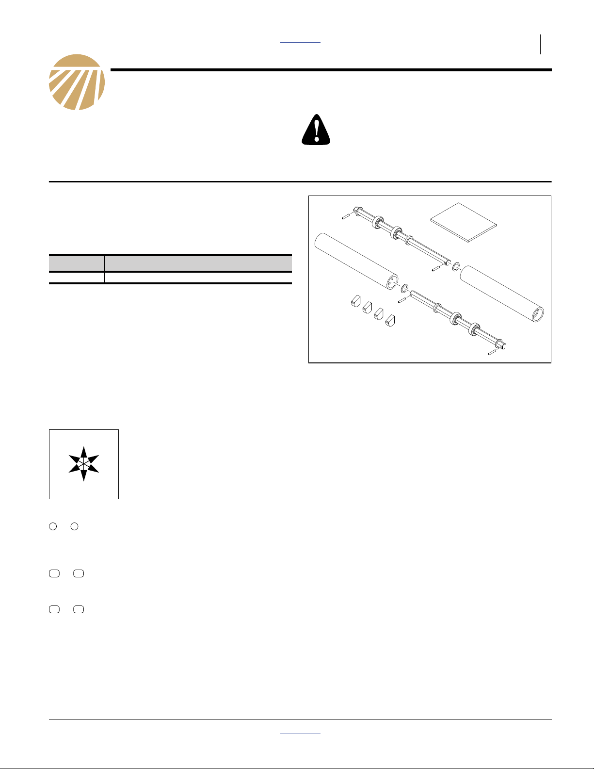
Figure 1
Kit Components
32009
© Copyright 2011 Printed 2012-02-21 Part Lists 166-367M

2 Great Plains Manufacturing, Inc. Front Page Part Lists Contact Drive Update
Pre-Assembly Preparation
Tools Required
• cutting torch
• wire or rod welder, and welding safety equipment,
including a fire extinguisher
• ground (earthing) rod, cable and clamp (or access to
suitable electrical safety ground reference conductor)
• suitable tractor for raising and unfolding air drill
• Great Plains 821-001C spray paint, or green exterior
enamel close to Pantone 356C, DuPont 262 or
PPG 43817
• basic hand tools
Work Location
1. Move the air drill to a location with:
• flat, non-combustible surface free of flammable
materials
• adequate illumination
• clear surface beneath for recovery of any falling or
dropped parts
Prepare Air Drill
2. Raise implement with tractor.
3. Unfold implement.
4. Install lift and transport locks.
5. Disconnect all harnesses to tractor.
6. Connect a grounding cable from the center section
main frame to earth ground
Burn and Fire Hazards:
This update requires cutting and welding thick metal. Perform
the work clear of flammable materials. Wear suitable protective equipment. Allow hot parts to cool before continuing
work.
Crushing and Sharp Object Hazards:
Be careful working near openers. Discs and other parts may
be sharp.
Equipment Damage Risk:
Disconnect harnesses and ground frame before welding.
Connected harnesses or ungrounded frame during welding
can result in permanent damage to seed monitor components.
166-367M Front Page Part Lists 02/21/2012

Dismount Contact Drive Front Page Part Lists Great Plains Manufacturing, Inc. 3
Dismount Contact Drive
Start with the right side of the implement.
Dismount Input Shaft
Refer to Figure 2
64
1
69
65
64
1
69
65
1
64
67
7. Relax the idler on the contact drive chain . Lift the
chain off 27T driving sprocket .
8. At the front shaft, remove and save two sets:
65
805-180C PIN ROLL 1/4 X 1 1/2 LG PLT
69
814-134C TIRE/WHEEL ASSY 13/5 X 6
9. Remove and save one 27T sprocket:
67
808-311C SPKT 50C27 X 7/8 HEX BORE
10. Remove, record and save all:
64
804-061C WASHER MACH 1.50 X 1.00 X 18GA
Record the count here:
67
Input Shaft Washer Count
Right, Outside
Right, Inside
Left, Outside
Left, Inside
11. Remove and save the shaft:
57
266-003D SHAFT 7/8 HEX 32.75
Disconnect Hold-Down Spring
Refer to Figure 3
12. At each of the hold-down springs , remove and
save one set:
61
803-020C NUT HEX 1/2-13 PLT
63
804-015C WASHER LOCK SPRING 1/2 PLT
58
266-250D TUBE RND 1OD X 7/32W X 1.44 L
59
802-226C HHCS 1/2-13X2 3/4 GR5
13. Leave the spring in place, but tie it up out of the
way. The lower lug (not shown in the figure) is torch
cut at step 31 on page 5.
66
66
Figure 2
Contact Drive Input Shaft
61
66
58
59
63
Figure 3
Disconnect Hold-Down Spring
32066
32066
02/21/2012 Front Page Part Lists 166-367M
4 Great Plains Manufacturing, Inc. Front Page Part Lists Contact Drive Update
Dismount Output Sprockets
Refer to Figure 4
14. Relax the idler on the contact drive output chain .
Lift the 144P chain off the 30T sprocket .
15. Remove and save 117P chain:
51
136-259D CHAIN RL #50 117 PITCHES
16. At the sprocket end of the shaft , drive out the roll
65
pin . This pin is not re-used.
17. Remove and save the first of two sprockets:
68
808-319C SPKT 50C30 X 7/8 HEX BORE
18. Remove and save any spacer washers (not shown):
64
804-061C WASHER MACH 1.50 X 1.00 X 18GA
in between the sprockets and the bearing.
Record the count here:
56
Output Shaft Washer Count
Right
68
64
2
56
68
65
68
2
51
Figure 4
Existing Drive Shaft
32066
Left
19. Remove and save the second of two 30T sprockets:
68
808-319C SPKT 50C30 X 7/8 HEX BORE
Remove Pivots and Arms
Refer to Figure 5
20. At the pivot shaft , drive all inside roll pins .
Optionally remove the outside pin as well. These
pins are not re-used.
21. Remove the shaft . It is not re-used.
22. Remove six sets of lock nuts and round head
shank neck bolts ( ), four flangettes and two
spherical bearings . These are not re-used.
The bearings in the drive arms remain installed.
23. Remove and save one of:
54
166-201H CONTACT DRIVE WELDMENT RIGHT
55
166-205H CONTACT DRIVE WELDMENT LEFT
24. Repeat step 7 through step 23 for the left side.
56 65
56
62
60 71
70
62
71
71
65
60
70
65
Figure 5
Existing Pivot Bearings at Frame
56
54
32066
166-367M Front Page Part Lists 02/21/2012
Cut Clearances Front Page Part Lists Great Plains Manufacturing, Inc. 5
Cut Clearances
Elongate Input Shaft Slot
The curved slots (4 places) for the contact drive input
shaft need to be elongated by 21.0 mm (0.83 in).
Refer to Figure 6 and Figure 21 on page 12
25. Make two copies of page 12 at 1:1 (100%) size (or
print at 100% size from the PDF of this manual), for
use as marking templates. A ruler image is included
on the page to verify that the copy is 1:1 scale.
26. Mark the elongation boundary (the dashed line) on
the tongue mount plates.
27. Use a torch, or similar tool capable of cutting thick
steel, to elongate the four curved slots . Check the
final edge against the template.
3
Notch Spring Brackets
Figure 6
Input Shaft Slot
3
29379
The parallel arm spring brackets (where the bottom
of the hold-down springs attach) need to have a notch
cut in them (8 places) to allow spring clearance at the
limits of the arm movement now allowed by the longer
curved slots.
Refer to Figure 7 and Figure 20 on page 11
28. Make four copies of page 11 at 1:1 (100%) size (or
print at 100% size from the PDF of this manual), for
use as marking templates. A ruler image is included
on the page to verify that the copy is 1:1 scale.
29. Mark the notch boundary (the dashed line) on the
tongue mount plates.
30. Protect neighboring machine parts from being overheated.
31. Use a torch, or similar tool capable of cutting thick
steel, to cut the notches. Check the final edges
against the template.
53 4
4
Figure 7
Spring Brackets with Notches
53
29434
02/21/2012 Front Page Part Lists 166-367M

6 Great Plains Manufacturing, Inc. Front Page Part Lists Contact Drive Update
Install Welded Parts
Install Down Stops
Lugs (4 places) are added to the tongue mount plates to
provide limit stops. This protects against machine damage in the event of low tire pressures.
Refer to Figure 8, Figure 9, Figure 22 (on page 13) and
Figure 23 (on page 14)
32. Remove paint from the area to be welded.
33. Make two copies each of page 13 and page 14
(4 total) at 1:1 (100%) size (or print at 100% size
from the PDF of this manual), for use as marking
templates. A ruler image is included on the pages to
verify that the copy is 1:1 scale.
34. Mark the location for each lug. Center-punching the
corners suffices.
35. Select four new:
13
266-294D CONTACT WHL DOWN STOP
Note: The lugs are symmetrical. The flat sides are iden-
tical.
36. Position each lug with one flat side to frame, the
other flat side up, curved side out, and canted 17
degrees forward. Tack weld. Re-check dimensions or
against template.
37. Allow tack welds to cool. Final weld all around with a
9 mm (3⁄8in) weld fillet.
Figure 8
Down Stop Installed
13
32075
17°
2.1 mm
2.1 mm (0.08 in) from bottom rear
13
77.6 mm
Figure 9
Down Stop Placement Dimensions
166-367M Front Page Part Lists 02/21/2012
corner of lug to vertical rear edge of
tongue mount plate.
77.6 mm (3.06 in) from bottom front
corner of lug to top edge of parallel
arm reinforcement plate below.
32076

Install Welded Parts Front Page Part Lists Great Plains Manufacturing, Inc. 7
Install Pivot Tubes
Start with the right side of the implement.
Refer to Figure 10, Figure 11and Figure 12
38. Remove paint from the frame around the former
bearing mount holes.
39. Select one new:
14
266-295D CONTACT WHL PVT TUBE
Insert the tube through the frame holes where the
previous pivot shaft was removed.
40. Adjust the tube position for a reveal of 81.0 mm
(3.10 in) on the outside of the frame (left reveal on
left side; right reveal on right side). Tack weld the
tube. Recheck the reveal.
41. At the outside face of the outside frame plate, and
the inside face of the inside frame plate, weld the
contact circumference of the tube/frame joints with a
9mm (3⁄8in) weld fillet .
Note: It is not necessary to fill the former bolt holes
during welding.
42. Repeat step 38 through step 41 for the left side.
43. Wait for the welds to cool.
44. At all welds, remove welding residue and any
charred paint. Apply matching green paint.
45. Allow paint to dry.
4
14
18
Figure 10
Pivot Tube and Bearings
4
12
12
16
15
29379
14
.epsi
100%
Figure 11
Pivot Tube Placement
14
5
Figure 12
Pivot Tube Weld
81.0 mm
(3.19 in)
32067
6
32067
02/21/2012 Front Page Part Lists 166-367M

8 Great Plains Manufacturing, Inc. Front Page Part Lists Contact Drive Update
Re-install Contact Drive Arms
Start with the right side of the implement. Two workers
may be needed due to parts that are held in alignment
for shaft insertion.
14
7
12
Install New Pivot Shaft
Refer to Figure 14
46. Select two new:
12
188-006V BEARING .880 HEX BORE 205DD
Insert and seat one bearing at each of the pivot
14 7
tubes . The orientation groove is to the inside of
the tube . The raised face of the inner race is to
the outside of the tube.
47. Select one new:
15
48. Select the saved:
54
55
depending on the side being worked on.
49. Select one each new:
16
Note: Make sure that the arms are above the new down
50. Hold the spacer tube against the inside face of
the inside arm bearing . Bring the existing arm
bearings into alignment with the new bearings .
From the inside, insert the shaft through the existing bearing, spacer tube and both pivot tube
bearings .
51. Select one new:
17
Slide this washer between the outside pivot tube
bearing and the outside arm bearing , Slide the
shaft through the washer and the outside arm
bearing .
52. Select the number of saved:
64
per the “Output Shaft” table (page 4) for the side of
the implement being worked on. Place these on the
inside end of the shaft.
53. Select two saved 30T sprockets:
68
Place them on the inside end of the shaft
54. Select two:
18
Drive the pins through the ends of the shaft.
55. Repeat step 46 through step 54 for the left side.
14
266-296D CONTACT WHEEL PIVOT SHAFT
166-201H CONTACT DRIVE WELDMENT RIGHT
166-205H CONTACT DRIVE WELDMENT LEFT
402-266D 7/8 HEX SHAFT SPACER TB X 9
stops (not shown) before the next step.
16
70 12
12
804-061C WASHER MACH 1.50 X 1.00 X 1
12 70
15 17
70
804-061C WASHER MACH 1.50 X 1.00 X 18GA
808-319C SPKT 50C30 X 7/8 HEX BORE
805-180C PIN ROLL 1/4 X 1 1/2 LG PLT
12
8
70
15
15
Figure 13
Bearing Orientation
17
14
70
18
70
Figure 14
Pivot Tube and Bearings
8
32104
12
12
16
15
54
68
64
68
29379
166-367M Front Page Part Lists 02/21/2012

Re-install Contact Drive Arms Front Page Part Lists Great Plains Manufacturing, Inc. 9
Re-Mount Drive Wheels
Start with the right side of the implement.
Refer to Figure 15
56. Select one saved:
57
266-003D SHAFT 7/8 HEX 32.75
Insert the shaft through the forward bearings on
the arms, and the curved slots in the tongue mount
plates.
57. Select the number of saved:
64
804-061C WASHER MACH 1.50 X 1.00 X 18GA
per the “Input Shaft” table (page 3) for the side of
the implement being worked on. Place these on their
respective ends of the shaft.
58. Select one saved:
67
808-311C SPKT 50C27 X 7/8 HEX BORE
Add it to the inside end of the shaft.
59. Select a saved 117P chain:
51
136-259D CHAIN RL #50 117 PITCHES
Route the chain over the sprocket .
60. Select two sets saved:
69
814-134C TIRE/WHEEL ASSY 13/5 X 6
65
805-180C PIN ROLL 1/4 X 1 1/2 LG PLT
Add one wheel to each end of the shaft. Secure with
roll pins.
51 67
70
69
65
51
70
57
64
67
Figure 15
Re-Install Drive Wheels
69
65
29379
Re-Install Chains
Refer to Figure 16
61. Route contact drive chain through idlers and
over driven sprocket (closest to contact drive
arm). Engage idlers .
62. Route contact drive output chain over driving
sprocket (furthest from contact drive arm).
Engage idlers .
68
2
51 1
68
1
52
1
Figure 16
Re-Install Chains
68
2
68
52
51
29379
02/21/2012 Front Page Part Lists 166-367M

10 Great Plains Manufacturing, Inc. Front Page Part Lists Contact Drive Update
Re-Connect Springs
Refer to Figure 17
63. Check spring rod length. Unless you have developed
a customer setting for your conditions, verify that the
spring is adjusted to factory default length.
6.7 cm (2.63 in)
27.3 cm (10.75 in)
with spring relaxed
Refer to Figure 18 and Figure 19
64. Select one set saved:
59
802-226C HHCS 1/2-13X2 3/4 GR5
58
266-250D TUBE RND 1OD X 7/32W X 1.44 L
63
804-015C WASHER LOCK SPRING 1/2 PLT
61
803-020C NUT HEX 1/2-13 PLT
65. Insert a tube into the lower hook of a hold-down
spring. Align the hold-down spring with the lower/
forward hole of the notched bracket . Secure with
59
bolt , lock washer and nut .
66. Repeat step 63 for the other spring on this side.
67. Repeat step 46 through step 66 for the left side of
the implement.
58
66
4
63 61
Figure 17
Hold-Down Spring Length
61
66
58
59
63
Figure 18
Re-connect Hold-Down Spring
66
32080
32066
53
4
59
Figure 19
Notched Hold-Down
166-367M Front Page Part Lists 02/21/2012
32079

Appendix Front Page Part Lists Great Plains Manufacturing, Inc. 11
Appendix
Notch Cutting Template
New Edge
New Edge
Figure 20: Notching Template
Existing Edge
Existing Edge
32072
02/21/2012 Front Page Part Lists 166-367M

12 Great Plains Manufacturing, Inc. Front Page Part Lists Contact Drive Update
Plate Cutting Template
Existing Bottom
New Bottom
21mm (0.83 in)
Figure 21: Plate Cutting Template
166-367M Front Page Part Lists 02/21/2012
32071

Appendix Front Page Part Lists Great Plains Manufacturing, Inc. 13
Stop Placement Template LH
Figure 22: Stop Placement Template - Left Hand
02/21/2012 Front Page Part Lists 166-367M
32073

14 Great Plains Manufacturing, Inc. Front Page Part Lists Contact Drive Update
Stop Placement Template - RH
Figure 23: Stop Placement Template - Right Hand
166-367M Front Page Part Lists 02/21/2012
32073

Appendix Front Page Part Lists Great Plains Manufacturing, Inc. 15
Part Lists
New Parts
The part call-out numbers in this list match all Figures in
these installation instructions. Part descriptions match
those in your updated Parts Manual.
Quantities are units (“ea”).
166-366A Kit Contents
Callout Quantity Part Number Part Description
11 1 166-367M MANUAL NTA 907 CONT DR UPDA
12 4 188-006V BEARING .880 HEX BORE 205DD
13 4 266-294D CONTACT WHL DOWN STOP
14 2 266-295D CONTACT WHL PVT TUBE
15 2 266-296D CONTACT WHEEL PIVOT SHAFT
16 2 402-266D 7/8 HEX SHAFT SPACER TB X 9
17 2 804-061C WASHER MACH 1.50 X 1.00 X 1
18 4 805-180C PIN ROLL 1/4 X 1 1/2 LG PLT
Other Parts
Callout Quantity Part Number Part Description
19 1 821-001C PAINT GP GREEN SPRAY CAN
Existing Parts Affected
The following existing parts are involved in the kit installation. The Disposition column indicates whether the part
is left in place, moved or not re-used.
The part call-out numbers in the list matches all Figures
in the installation instructions. The descriptions match
those in your air drill Parts manual.
Callout Qty Part No. Part Description Part Disposition
51 2 136-259D CHAIN RL #50 117 PITCHES Removed and re-installed.
52 2 136-260D CHAIN RL #50 144 PITCHES Removed and re-installed.
53 2 166-196H ARM PARALLEL W/ SPNG BRKT WELD Modified in place.
54 1 166-201H CONTACT DRIVE WELDMENT RIGHT Removed and re-installed.
55 1 166-205H CONTACT DRIVE WELDMENT LEFT Removed and re-installed.
56 2 166-953D HEX SHAFT 7/8X20.56 LONG Removed. Not re-used.
57 2 266-003D SHAFT 7/8 HEX 32.75 Removed and re-installed.
58 4 266-250D TUBE RND 1OD X 7/32W X 1.44 L Removed and re-installed.
59 4 802-226C HHCS 1/2-13X2 3/4 GR5 Removed and re-installed.
60 6 802-282C RHSNB 5/16-18X1 GR5 Removed and re-installed.
61 4 803-020C NUT HEX 1/2-13 PLT Removed and re-installed.
62 12 803-177C NUT HEX FLG TP LK 5/16-18ZNYCR Removed and re-installed.
63 2 804-015C WASHER LOCK SPRING 1/2 PLT Removed and re-installed.
64 4-8 804-061C WASHER MACH 1.50 X 1.00 X 18GA Removed and re-installed.
65 8 805-180C PIN ROLL 1/4 X 1 1/2 LG PLT Removed. Not re-used.
66 4 807-055C SPRING HOLD DOWN HD COULTER Disconnected and re-connected.
67 2 808-311C SPKT 50C27 X 7/8 HEX BORE Removed and re-installed.
68 4 808-319C SPKT 50C30 X 7/8 HEX BORE Removed and re-installed.
69 4 814-134C TIRE/WHEEL ASSY 13/5 X 6 Removed and re-installed.
70 4 822-119C BRG 7/8HEXX2.05OD SPH Removed and re-installed.
71 8 822-175C FLANGETTE 52 3-BOLT PLT Removed and re-installed.
02/21/2012 Front Page Part Lists 166-367M

16 Great Plains Manufacturing, Inc. Front Page Part Lists Contact Drive Update
Abbreviations
#50 Number 50 chain link OD Outside Diameter
ASSY Assembly PLT Plated
BRG Bearing PVT Pivot
BRKT Bracket RHSNB Round Head Shank Neck Bolt
DR Drive RL Roller
FLG Flanged SPH Spherical
GA Gauge SPKT Sprocket
GP Great Plains TB Tube
GR5 Grade 5 TP LK Top Lock
HD Heavy Duty UPDA Update
HEX Hexagonal W Width
HHCS Hex Head Cap Screw W/ with
L, LG Long WHL Wheel
MACH Machined X By
NTA No-Till Air (drill) ZNYCR Zinc Chromate
Great Plains Manufacturing, Inc.
Corporate Office P.O. Box 5060
Salina, Kansas 67402-5060 USA
166-367M Front Page Part Lists 02/21/2012
 Loading...