

Page 1
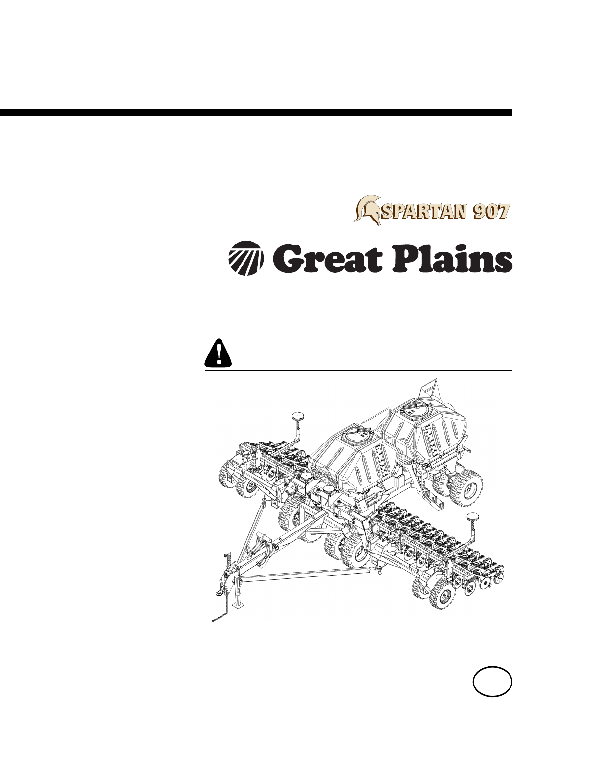
Table of Contents Index
9 Meter/30 Foot No-Till Air Drills
Operator Manual
2012+ NTA907 or NTA3007
Manufacturing, Inc.
www.greatplainsmfg.com
Read the Operator manual entirely. When you see this symbol, the
subsequent instructions and warnings are serious - follow without
exception. Your life and the lives of others depend on it!
32440
Illustrations may show optional equipment not supplied with standard unit, and may
show model NTA907, NTA907HD, NTA3007 or NTA3007HD air drills.
ORIGINAL INSTRUCTIONS
© Copyright 2011 Printed 2012-07-02 166-371M
Table of Contents Index
EN
Page 2

Table of Contents Index
166-371M Table of Contents Index 2012-07-02
Page 3

Great Plains Manufacturing, Inc. Cover Index iii
Table of Contents
Equipment Identification .............................................1
North American Models NTA3007..................................1
Export Models NTA907 ..................................................1
Machine Record .............................................................2
Machine Log...............................................................2
Machine Details..........................................................2
Dealer Information......................................................2
Great Plains Regional Agent ...................................... 2
Introduction ..................................................................3
Description of Unit ..........................................................3
Intended Usage ..............................................................3
Using This Manual
Document Family........................................................4
Definitions................................................................... 4
Owner Assistance ..........................................................4
Important Safety Information ......................................5
Safety Decals ...............................................................11
Preparation and Setup ...............................................26
Initial Setup...................................................................26
Seasonal Setup ............................................................26
Pre-Planting Setup .......................................................26
Hitching Tractor to Drill.................................................27
Hydraulic Hose Hook-Up..............................................28
Brake Hook-Up (Option)...............................................29
Electrical Hook-Up........................................................30
Beacon Operation (NTA907 only) ............................31
Stow Wheel Chocks .....................................................31
Heights and Levelling ...................................................32
Marker Setup................................................................32
Operating Instructions...............................................33
Pre-Start Checklist .......................................................33
CFM Overview.......................................................... 33
Unfolding the Drill .........................................................34
Unfold: Summary of Steps........................................35
Lowering and Raising Drill............................................42
Lowering...................................................................42
Raising .....................................................................43
Folding the Drill ............................................................44
Fold: Summary of Steps...........................................45
Fold: Set Tractor for Fold..........................................47
Fold: Fold Wings.......................................................47
Transporting the Air Drill...............................................50
Tractor Requirements............................................... 51
Transport Checklist .................................................. 51
Brake Operation (Option)............................................. 52
Single-Line Hydraulic Brake Operation ................ 52
Dual-Line Air/Hydraulic Brake Operation .............52
Ladder Operations ....................................................... 54
Using Ladder............................................................54
Storing Ladder.......................................................... 54
Hopper Lids.................................................................. 55
Strainer..................................................................... 57
Meter Doors ................................................................. 57
Meter Door Opening................................................. 58
Meter Door Closing .................................................. 58
Auger Operations (Option)........................................... 59
Deploying Auger....................................................... 60
Auger Hydraulic Controls ......................................... 62
Tractor Lever for Auger ........................................ 62
Selector Valve ...................................................... 62
Auger Direction Valve .......................................... 63
Storing Auger ........................................................... 64
Orient Inlet and Outlet .......................................... 64
Loading Materials......................................................... 65
Loading Material Safely............................................ 65
Loading: Use a Tractor............................................. 66
Loading: Select Hoppers to Use .............................. 66
Loading: Air-Out System .......................................... 66
Loading: Prepare Hopper(s)..................................... 66
Loading: with Auger ................................................. 67
Loading: Close-Out .................................................. 67
Collection Chute Operation.......................................... 68
Using the Collection Chute....................................... 68
Calibration Crank ......................................................... 69
Fan Operation .............................................................. 71
Marker Operation (Option) ........................................... 73
Field Operations........................................................... 75
Field Operation ............................................................ 76
Seed Monitor............................................................76
Unloading Materials ..................................................... 77
Unloading Without Auger ......................................... 77
Auger Unloading: Rear Hopper................................ 78
Auger Unloading: Front Hopper ............................... 80
Parking......................................................................... 81
Storage ........................................................................ 82
Adjustments ............................................................... 83
Setting Material Rates.................................................. 84
Check Contact Tires................................................. 84
© Copyright 2009, 2010, 2011 All rights Reserved
Great Plains Manufacturing, Inc. provides this publication “as is” without warranty of any kind, either expressed or implied. While every precaution has been
taken in the preparation of this manual, Great Plains Manufacturing, Inc. assumes no responsibility for errors or omissions. Neither is any liability assumed for
damages resulting from the use of the information contained herein. Great Plains Manufacturing, Inc. reserves the right to revise and improve its products as
it sees fit. This publication describes the state of this product at the time of its publication, and may not reflect the product in the future.
2012-07-02 Cover Index 166-371M
Trademarks of Great Plains Manufacturing, Inc. include: Singulator Plus, Swath Command, Terra-Tine.
Registered Trademarks of Great Plains Manufacturing, Inc. include:
Air-Pro, Clear-Shot, Discovator, Great Plains, Land Pride, MeterCone, Nutri-Pro, Seed-Lok, Solid Stand,
Terra-Guard, Turbo-Chisel, Turbo-Chopper, Turbo Max, Turbo-Till, Ultra-Till, Verti-Till, Whirlfilter, Yield-Pro.
Brand and Product Names that appear and are owned by others are trademarks of their respective owners.
Printed in the United States of America
Page 4

iv NTA907 or NTA3007 Table of Contents Index Great Plains Manufacturing, Inc.
Check Flute Shaft Type ........................................... 84
Find Your Chart and Rate ........................................ 85
Monitor Material Configuration................................. 86
Meter Rate Adjustment ............................................ 87
Seed Meter Final Drive Range............................. 88
Disable a Seed Meter........................................... 88
Setting Variable Rate Gearbox ............................ 89
Manual Rate Setting............................................. 89
Variable Rate (Servo) Rate Setting...................... 89
Meter Calibration.......................................................... 90
Calibration Crank Revolutions.............................. 92
Variable Rate (Servo) Calibration ............................ 95
Calibration Crank Revolutions.............................. 95
Contact Drive Adjustment ............................................ 97
Fan Speed Adjustments............................................... 98
Recommended Fan Speeds ................................ 98
Implement Lift Switch Adjustment................................ 99
Planting Depth Adjustments....................................... 100
Opener Down-Force (Hydraulic) ................................ 101
Adjusting Hydraulic Down Pressure....................... 102
Control Valve Overview ......................................... 103
Setting the Bypass Valve ....................................... 104
Bypass with LS or PFC Closed Systems ............... 105
Priority Flow Hydraulic Systems............................. 105
Opener Sub-Frame Adjustment ................................. 106
Adjusting Weight Transfer...................................... 107
Frame-Mounted Coulters (Option) ............................. 108
Frame-Mounted Coulter Force............................... 109
07 Series Row Unit Adjustments ............................... 110
Row Unit Spring Adjustment .................................. 111
Disc Blade Adjustments ......................................... 111
Adjusting Disk Contact ....................................... 112
Disc Scraper Adjustments...................................... 112
Seed Firmer Adjustments ...................................... 113
Opener Depth (Press Wheel Height) ..................... 114
Marker Adjustments ................................................... 115
Marker Disc Adjustment......................................... 115
Troubleshooting....................................................... 116
Brake Troubleshooting (Option)................................. 120
Maintenance and Lubrication ................................. 122
Maintenance .............................................................. 123
Chain Maintenance ................................................ 123
Material Clean-Out................................................. 124
Problem Clean-Out ............................................ 125
Removing Meter Box.......................................... 125
Hopper Entry ...................................................... 126
Hydraulic Maintenance .......................................... 128
Hydraulic Maintenance Safety Information ........ 128
Bleeding Hydraulics ........................................... 128
Bleeding Tilt Hydraulics ......................................129
Bleeding Fold Hydraulics ....................................130
Bleeding Hook Hydraulics...................................130
Bleeding Down-Pressure Hydraulics ..................131
In-Line Filter........................................................132
Marker Maintenance ...............................................133
Marker Shear Bolt...............................................133
Marker Hydraulic Bleeding..................................133
Marker Chain Length ..........................................134
Marker Grease Seal............................................134
Brake Maintenance (Option)...................................135
Brake Line Charge and Bleed.............................135
Air Brake Maintenance .......................................137
Brake Drum and Liner Maintenance ...................138
Brake Shoe Replacement...................................139
Brake Drum Maintenance ...................................143
Mounting Wheels ................................................144
Test and Adjust Brakes.......................................144
Levelling Drill ..........................................................145
Section Alignment...................................................145
Tool Bar Heights .................................................146
Seed Flap Replacement .........................................147
Beacon Maintenance (NTA907 only)..........................147
Lubrication and Scheduled Maintenance ...................148
Options ......................................................................157
Appendix A - Reference Information ......................163
Specifications and Capacities.....................................163
NTA907 Export Models...........................................163
NTA3007 North America Models ............................164
Dimensions (Transport) NTA907 Export Models........165
Tire Inflation Chart ......................................................166
Hydraulic Connectors and Torque..............................166
Torque Values Chart ..................................................167
Seed Hose Port Maps ................................................168
Monitor Setup Data.....................................................174
Chain Routing.............................................................175
LH Contact Drive Chains ........................................175
Gearbox and Meter Chains.....................................176
Hydraulic Diagrams ....................................................177
Appendix B - Initial Setup ........................................183
Console Installation ....................................................183
Initial Marker Setup.....................................................183
Marker Extension....................................................183
Marker Speed .........................................................184
Appendix C - Option Installation.............................185
Changing Meter Flutes ...............................................185
Warranty .....................................................................187
Index ..........................................................................189
166-371M Table of Contents Index 2012-07-02
Page 5

Great Plains Manufacturing, Inc. Table of Contents Index 1
Equipment Identification
This Operator manual applies to the following Great
Plains pull-type integrated air drill seeders:
NTA907-3610 9m, 36-row, 25.4cm (10in) spacing
NTA907-4875 9m, 48-row, 19.1cm (7.5in) spacing
NTA907-6006 9m, 60-row, 15.0cm (5.9in) spacing
NTA3007-3610 30 foot, 36-row, 10 inch spacing
NTA3007-4875 30 foot, 48-row, 7.5 inch spacing
NTA3007-6006 30 foot, 60-row, 6 (5.9) inch spacing
See “Specifications and Capacities” on page 163 for
precise swath information.
Refer to Figure 1
For positive equipment identification, consult the serial
number plate located on the rear frame cross-member
1
below and left of fan.
Note: The present manual does not apply to “HD” models
NTA907HDor NTA3007HD. See manual 166-207M
for HD drills.
Label/Plate Location
N
*P 2 *
1
Figure 1
32450
North American Models NTA3007
Models NTA3007 are built to North American highway
transport standards.
Refer to Figure 2 (which is NOT from an actual machine)
The serial number plate provides the model number and
serial number specific to your machine.
See “Transporting the Air Drill” on page 50
and “Specifications and Capacities” on page 163 for
additional weights and measurements.
Export Models NTA907
Models NTA907 are built to European highway transport
standards.
Refer to Figure 3 (which is NOT from an actual machine)
If you, or the dealer, have added Options not originally
ordered with the machine, or removed Options that were
originally ordered, the weights and measurements no
longer are accurate for your machine. Update the Record
on the next page upon modifications.
Figure 2: NTA3007:
Example Serial Number Plate
32162
Figure 3: NTA907:
32230
Example Machine Label
2012-07-02 Table of Contents Index 166-371M
Page 6

2 NTA907 or NTA3007 Table of Contents Index Great Plains Manufacturing, Inc.
Machine Record
Machine Details
Record your machine details in the Log at right. If you
replace this manual, be sure to transfer this information
to the similar page of the new manual.
If you add or remove Options, update the Log. If the page
cannot be legibly updated, request or print a new
Operator manual.
Dealer Information
My Customer
Number / ID
Dealer Name
Street
Place
Post Code
Country
Voice
Machine Log
Machine Model
Serial Number
Working Width
Transport Width
Maximum Tare Weight
Maximum Payload
Maximum Gross Weight
Maximum Axle Load
Year of Manufacture
Date of Delivery
Date in Service
Options
Fax
Web
Email
Great Plains Regional Agent
(If different than those on page 4)
Agent Voice
Street Fax
Place Web
Post Code Email
Country
166-371M Table of Contents Index 2012-07-02
Page 7
Great Plains Manufacturing, Inc. Table of Contents Index 3
Introduction
Great Plains welcomes you to its growing family of new
product owners. Your 9m/30ft No-Till Air Drill has been
designed with care and built by skilled workers using
quality materials. Proper setup, maintenance, and safe
operating practices will help you get years of satisfactory
use from the machine.
Before placing the machine into service for the first time,
read and understand this manual, in particular the
“Important Safety Information”, pages 5 to 25. Have
all operators read this manual before allowing them to
work with the machine.
Description of Unit
The NTA907 or NTA3007 is a pull-type integrated air drill
seeder. The implement folds for narrow 3 m (9 ft. 81⁄2in.)
transport.
A hydraulic fan supplies the material delivery system.
Ground-driven fluted shafts below the hoppers meter the
seed or fertilizer (the materials) into the air flow. Meter
chambers and tower manifolds evenly divide the material
flow, and deliver equal volumes to each opener row.
The cart has dual 3500 litre (100 bu) hoppers for
separate or simultaneous delivery of seed and/or
granulated dry fertilizer. Each hopper has an
independent metering system with user-preset infinite
ratio gearboxes. Console-controlled variable rate meter
servos are optional.
The NTA907 or NTA3007 has double-disc Series 07
openers, suitable for conventional till and, minimum-till
conditions. With optional coulters, the air drill is suitable
for moderate no-till conditions.
Brakes are standard on model NTA907 and optional on
model NTA3007. Service brakes are operated by air or
hydraulic lines to the tractor.
Hydraulic weight transfer (of cart weight to implement,
and from implement centre section to wings) is standard.
Other options include auger, field markers, tramline kits,
high rate flutes, and alternate discs, scrapers and
firmers.
Do not modify the drill except as instructed by Great
Plains. Do not use attachments other than as provided
by or authorized by Great Plains.
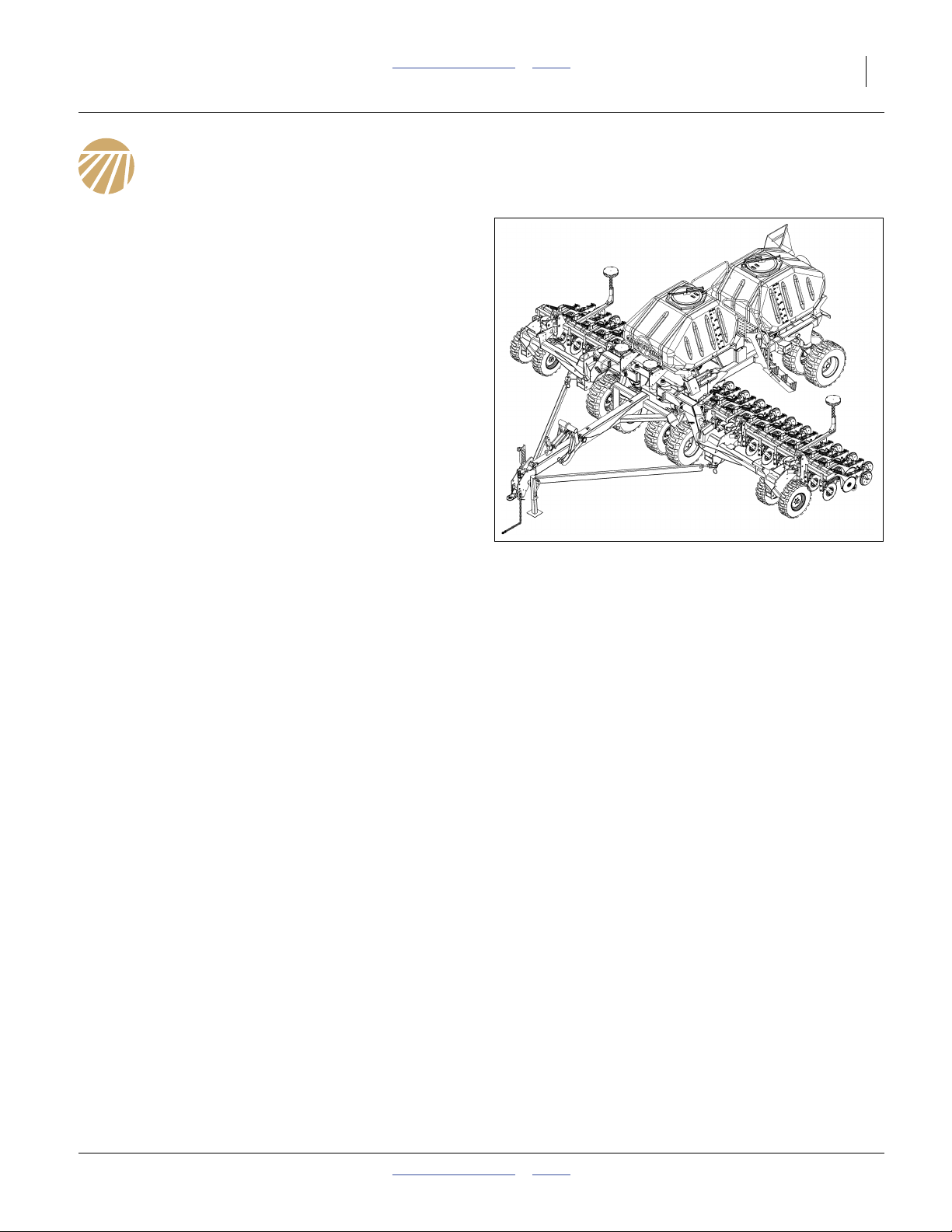
Figure 4
NTA907 or NTA3007 Drill
Intended Usage
Use the NTA907 or NTA3007 to seed and fertilize
production-agriculture crops only.
The intended use requires that safety features are
unimpaired, that machine systems be in proper working
order, and that the material rates have been correctly
configured and verified. Use only Great Plains
authorized replacement parts.
Faults in safety features, including missing or illegible
safety decals, must be remedied prior to machine use.
To keep the machine in proper working order, comply
with operating instructions, perform periodic
maintenance, and repair or replace worn or damaged
parts.
This is a volumetric seeding implement. The provided
seed rate charts (manual 167-085B) are based on
materials which likely vary from yours. Grain size, grain
shape, density, surface texture, foreign matter,
treatments, coatings, humidity, field speed, soil
conditions and normal wear on tires and meters cause
rates to vary from the charts. Calibration is essential for
satisfactory results.
32440
2012-07-02 Table of Contents Index 166-371M
Page 8

4 NTA907 or NTA3007 Table of Contents Index Great Plains Manufacturing, Inc.
Using This Manual
This manual will familiarize you with safety, hitching,
operation, adjustments, troubleshooting, and
maintenance. Read this manual and follow the
recommendations to help ensure safe and efficient
operation.
The information in this manual is current at printing.
Some parts may change to assure top performance.
Document Family
166-371M Operator Manual (thisa document)
167-085B Seed Rate Charts
166-371P Parts Manual
166-263M Variable Rate Kit Installation
113-850M Marker Installation
110011516 DICKEY-john® Quick Start Guide
110011375 DICKEY-john® Air Cart Control manual
110111543 DICKEY-john® Tramline Kit instructions
Definitions
Safety admonishment signal words are described on
page 5.
The following terms are also used throughout this
manual.
Owner Assistance
If you need customer service or repair parts, contact a
Great Plains dealer. They have trained personnel, repair
parts and equipment specially designed for Great Plains
products.
Your machine’s parts were specially designed and
should only be replaced with Great Plains parts. Always
use the serial and model number (page 2) when ordering
parts from your Great Plains dealer.
Your Great Plains dealer wants you to be satisfied with
your new machine. If you do not understand any part of
this manual or are not satisfied with the service received,
please take the following actions.
1. Discuss the matter with your dealership service
manager. Make sure they are aware of any problems
so they can assist you.
2. If you are still unsatisfied, seek out the owner or
general manager of the dealership.
For further assistance contact Great Plains via the Agent
recorded on page 2, or at:
For U.K. and Europe
SIMBA Great Plains
Woodbridge Road Ind. East
Sleaford
Lincolnshire NG34 7EW England
Identifies an Economic (not a Safety) Risk:
NOTICE provides a crucial point of information related to the
current topic. Read and follow the instructions to avoid damage
to equipment and ensure desired field results.
Note: This form sets off useful information related to the
current topic, or forestalls possible
misunderstanding.
Right-hand and left-hand as used in
this manual are determined by facing
the direction the machine will travel
while in use unless otherwise stated.
An orientation rose in some line art
illustrations shows the directions of:
Up, Back, Left, Down, Front, Right.
a. If you prefer a manual that is metric-only, request a copy of 166-371M-ENG from your dealer or from Great Plains.
R
F
U
B
L
D
Voice: +44 (0) 1529 304654
Fax: +44 (0) 1529 413468
Email: simba.international@simba.co.uk
For Other Regions
Great Plains Manufacturing, Inc.
PO Box 5060
Salina KS 67402-5060 USA
Voice: +1 785-823-3276
Fax: +1 785-822-6722
Email: gp_web_cs@greatplainsmfg.com
166-371M Table of Contents Index 2012-07-02
Page 9
Great Plains Manufacturing, Inc. Table of Contents Index 5
Important Safety Information
Look for Safety Symbol
The SAFETY ALERT SYMBOLa indicates there is a
potential hazard to personal safety involved and extra
safety precaution must be taken. When you see this
symbol, be alert and carefully read the message that
follows it. In addition to design and configuration of
equipment, hazard control and accident prevention are
dependent upon the awareness, concern, prudence and
proper training of personnel involved in the operation,
transport, maintenance and storage of equipment.
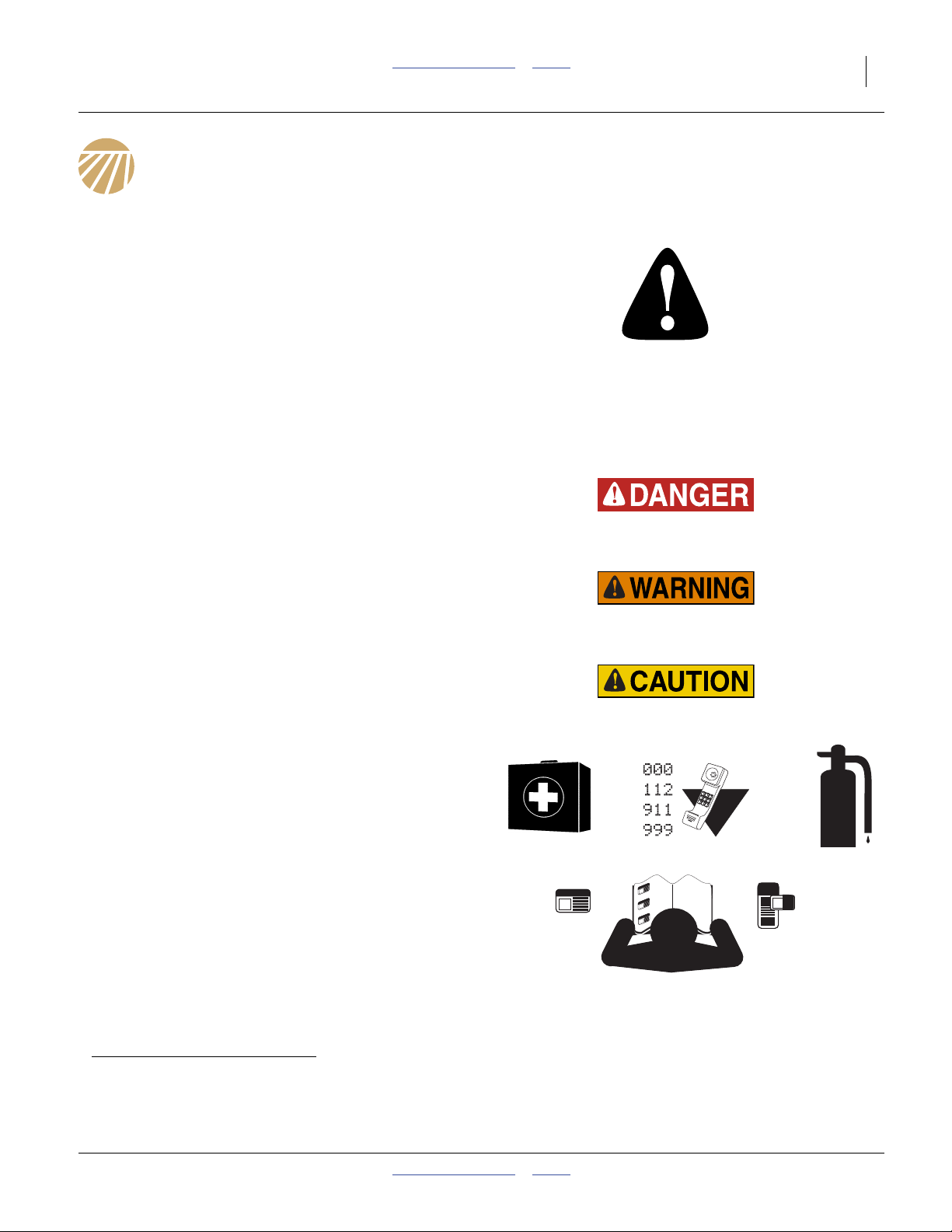
Be Aware of Signal Words
Signal words designate a degree or level of hazard
seriousness.
DANGER, and the colour Safety Red, indicate an
imminent hazard which, if not avoided, will result in death
or serious injury. This signal word is limited to the most
extreme situations, typically for machine components
that, for functional purposes, cannot be guarded.
WARNING, and the colour Safety Orange, indicate a
potential hazard which, if not avoided, could result in
death or serious injury, and includes hazards that are
exposed when guards are removed. It may also be used
to alert against unsafe practices.
CAUTION, and the colour Safety Yellowb, indicate a
potential hazard which, if not avoided, may result in
minor or moderate injury. It may also be used to alert
against unsafe practices.
Prepare for Emergencies
▲ Be prepared if a fire starts
▲ Keep a first aid kit and fire extinguisher handy.
▲ Keep emergency numbers for doctor, ambulance, hospital
and fire department near phone.
Be Familiar with Safety Decals
▲ Read and understand “WarningSafety Reflectors and
Decals” on page 11, thoroughly.
▲ Read all instructions noted on the decals.
▲ Keep decals clean. Replace damaged, faded and illegible
decals.
a. Symbols and safety colours in this manual, and on machine model NTA3007, are based on ANSI standard Z535.
Pictogram symbols and colours on model NTA907 are based on ISO standard 3864.
b. Pictograms (language-free safety decals), found on models NTA907, are generally on a Safety Yellow background regardless of
hazard severity. Rely on the illustrations, and the manual, and not the colour, to classify the severity of the hazard.
2012-07-02 Table of Contents Index 166-371M
Page 10

6 NTA907 or NTA3007 Table of Contents Index Great Plains Manufacturing, Inc.
Wear Protective Equipment
▲ Wear protective clothing and equipment.
▲ Wear clothing and equipment appropriate for the job. Avoid
loose-fitting clothing.
▲ Because prolonged exposure to loud noise can cause
hearing impairment or hearing loss, wear suitable hearing
protection such as earmuffs or earplugs.
▲ Because operating equipment safely requires your full
attention, avoid wearing entertainment headphones while
operating machinery.
Use A Safety Chain
▲ Use a safety chain to help control drawn machinery should
it separate from tractor draw-bar.
▲ Use a chain with a strength rating equal to or greater than
the gross weight of towed machinery.
▲ Attach chain to tractor draw-bar support or other specified
anchor location. Allow only enough slack in chain to permit
turning.
▲ Replace chain if any links or end fittings are broken,
stretched or damaged.
▲ Do not use safety chain for towing.
Avoid High Pressure Fluids
Escaping fluid under pressure can penetrate the skin,
causing serious injury.
▲ Avoid the hazard by relieving pressure before disconnecting
hydraulic lines.
▲ Use a piece of paper or cardboard, NOT BODY PARTS, to
check for suspected leaks.
▲ Wear protective gloves and safety glasses or goggles when
working with hydraulic systems.
▲ If an accident occurs, seek immediate medical assistance
from a physician familiar with this type of injury.
166-371M Table of Contents Index 2012-07-02
Page 11
Great Plains Manufacturing, Inc. Table of Contents Index Important Safety Information 7
Handle Chemicals Properly
Agricultural chemicals can be dangerous. Improper use
can seriously injure persons, animals, plants, soil and
property.
▲ Do not use liquid seed treatments with the NTA907 or
NTA3007.
▲ Read and follow chemical manufacturer’s instructions.
▲ Wear protective clothing.
▲ Handle all chemicals with care.
▲ Avoid inhaling smoke from any type of chemical fire.
▲ Never drain, rinse or wash dispensers within 30m (100 feet)
of a freshwater source, nor at a car wash.
▲ Store or dispose of unused chemicals as specified by
chemical manufacturer.
▲ Dispose of empty chemical containers properly. Laws
generally require power rinsing or rinsing three times,
followed by perforation of the container to prevent re-use.
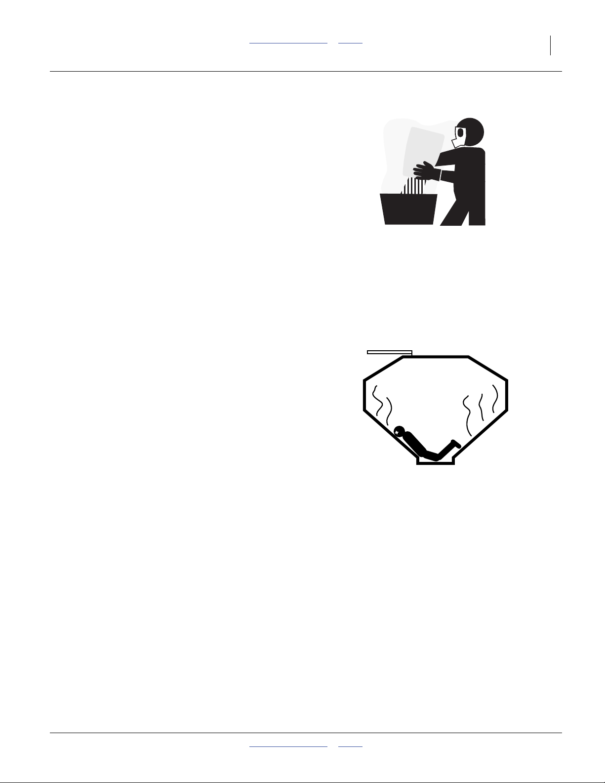
Confined Space
With materials loaded, or once used for hazardous
fertilizers, or seeds with hazardous treatments, a hopper
may become
“permit-required confined space”
under applicable statutes, regulations, insurance rules or
business policy. The vent tube structure in the hopper
has features to assist escape, and is not for routine entry.
▲ A hopper that is full or merely appears full can be an
entrapment hazard. You can sink entirely into the material,
or into an oxygen-deficient void, and suffocate in a matter
of seconds. Bridges and crusts are especially dangerous.
▲ When hazardous fumes are present, you can be quickly
overcome even with the hopper lid open.
▲ Do not enter a hopper for material loading, material
unloading, hopper cleaning or meter maintenance.
▲ Clean hopper by power washing from outside hopper top.
▲ Perform meter maintenance by removing meters from
bottom of empty hopper.
▲ If obstruction removal or repair requires hopper entry, have
the work performed by a team trained in confined space
procedures. See “Hopper Entry” on page 126.
2012-07-02 Table of Contents Index 166-371M
Page 12
8 NTA907 or NTA3007 Table of Contents Index Great Plains Manufacturing, Inc.
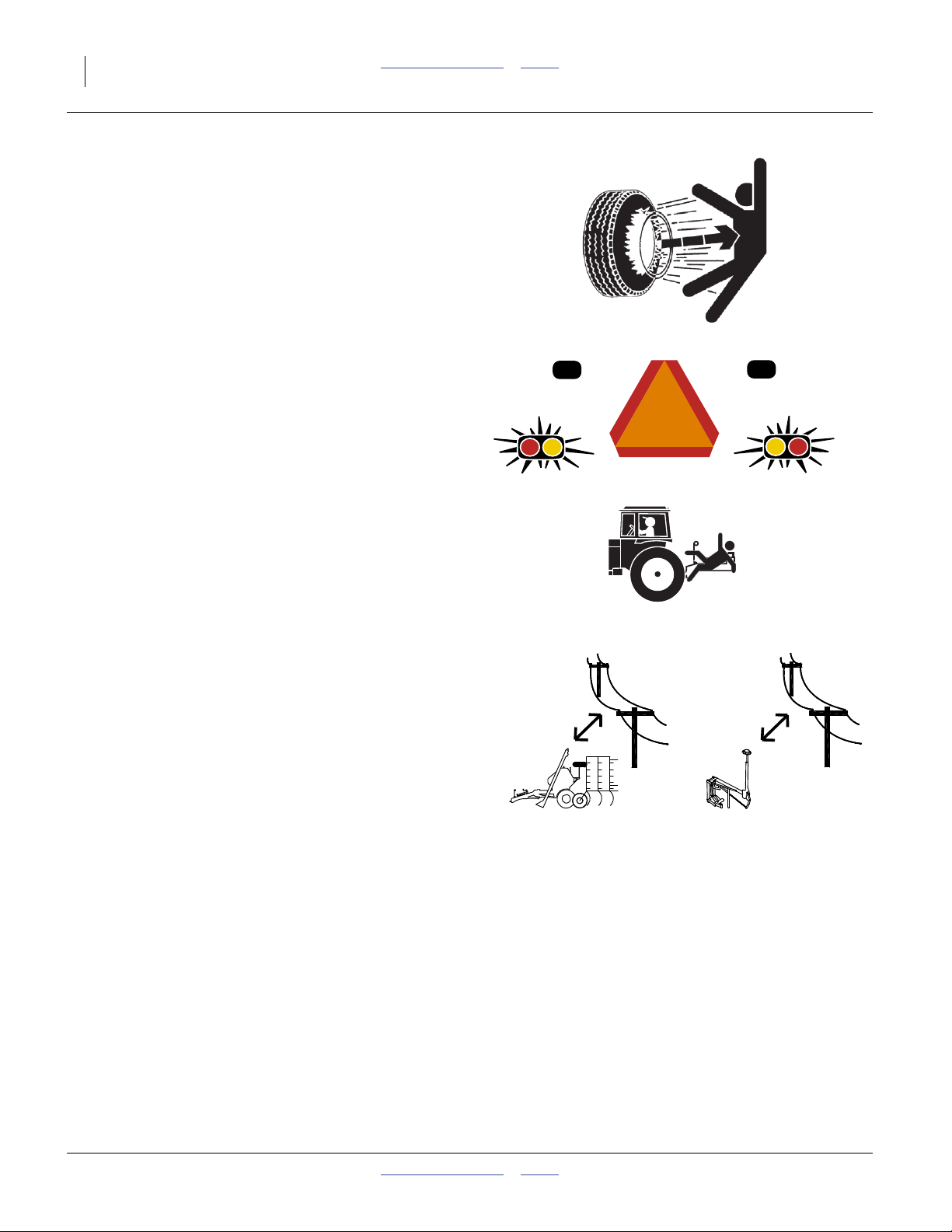
Tire Safety
Tire changing can be dangerous and should be
performed by trained personnel using correct tools and
equipment.
▲ When inflating tires, use a clip-on chuck and extension hose
long enough for you to stand to one side–not in front of or
over tire assembly. Use a safety cage if available.
▲ When removing and installing wheels, use wheel-handling
equipment adequate for weight involved.
Use Safety Lights and Devices
Slow-moving tractors and towed implements can create
a hazard when driven on public roads. They are difficult
to see, especially at night.
▲ Use flashing warning lights and turn signals whenever
driving on public roads.
Use lights and devices provided with implement
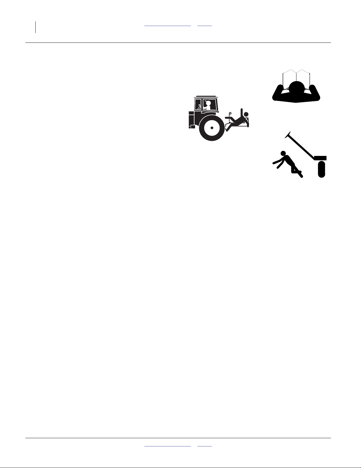
Keep Riders Off Machinery
Riders obstruct the operator’s view. Riders could be
struck by foreign objects or thrown from the machine.
▲ Never allow children to operate equipment.
▲ Keep all bystanders away from machine during operation.
Remain Clear of Overhead Lines
▲ If the drill contacts a power line, lethal voltage may be
present on all metal parts. At higher voltage, the drill does
not need to be in line contact for the hazard to exist.
Maintain at least 3 m (10 foot) clearance.
▲ Electrocution can occur without direct contact between the
energized drill and a person near the drill.
▲ Watch for sagging, damaged or low electrical lines. The
auger could contact lines lower than 5.3 m (17.5 feet).
Overhead lines at farm structures are a particular hazard.
An auger is at risk from lines lower than 9 m (28 feet).
▲ Watch for all electrical lines during folding, unfolding,
marker and most especially auger operations. Use a spotter
during these operations. Know the location and height of all
lines during loading, transport and in fields.
▲ If an electrical hazard is observed while on the ground near
the applicator, hop at least 30 m (100 feet) away with both
feet together and summon professional help. At higher
voltage, lethal voltage gradients can also be present at the
soil surface.
▲ Consult your tractor manual for advice on how to respond
to an electrical hazard event while in the cab.
166-371M Table of Contents Index 2012-07-02
Page 13
Great Plains Manufacturing, Inc. Table of Contents Index Important Safety Information 9
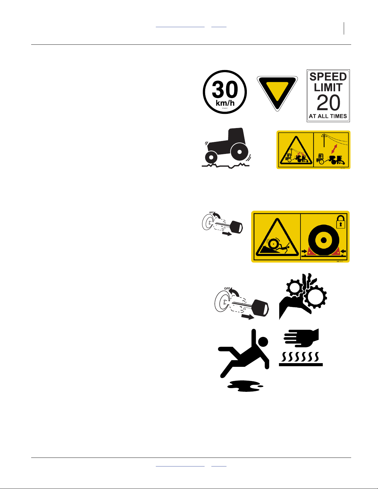
Transport Machinery Safely
Maximum transport speed for implement is
30 km/h or 20 mph. Some rough terrains require a
slower speed. Sudden braking can cause a towed load to
swerve and upset.
▲ Do not exceed 30 km/h or 20 mph. Never travel at a speed
which does not allow adequate control of steering and
stopping. Reduce speed if towed load is not equipped with
brakes.
▲ Comply with state and local laws.
▲ Do not tow an implement that, when fully loaded, weighs
more than 1.5 times the weight of towing vehicle.
▲ Carry reflectors or flags to mark drill in case of breakdown
on the road.
▲ Keep clear of overhead power lines and other obstructions
when transporting. Refer to transport dimensions under
“Specifications and Capacities” on page 163.
▲ Do not fold or unfold the drill while the tractor is moving
Shutdown and Storage
▲ Unfold and lower drill.
▲ Block tires with wheel chocks provided.
▲ Detach and store drill in an area where children normally
do not play.
Practice Safe Maintenance
▲ Understand procedure before doing work. Use proper
tools and equipment. Refer to this manual. For brake
work, see specific safety information beginning on
page 138.
▲ Work in a clean, dry area.
▲ Unfold and lower the drill, put tractor in park, turn off
engine, and remove key before performing maintenance. If
work must be performed with implement raised, use centre
section lift lock and gauge lock channels provided.
▲ Make sure all moving parts have stopped and all system
pressure is relieved.
▲ Allow drill to cool completely.
▲ Disconnect battery grounding cable (-) before servicing or
adjusting electrical systems.
▲ Welding: Disconnect battery grounding. Protect hydraulic
lines. Avoid fumes from heated paint.
▲ Inspect all parts. Make sure parts are in good condition
and installed properly.
▲ Remove buildup of grease, oil or debris.
▲ Remove all tools and unused parts from drill before
operation.
2012-07-02 Table of Contents Index 166-371M
Page 14
10 NTA907 or NTA3007 Table of Contents Index Great Plains Manufacturing, Inc.
Safety At All Times
Thoroughly read and understand the instructions in this
manual before operation. Read all instructions noted on
the safety decals.
▲ Be familiar with all drill functions.
▲ Operate machinery from the driver’s seat only.
▲ Do not leave drill unattended with tractor engine running.
▲ Do not stand between the tractor and drill during hitching.
▲ Keep hands, feet and clothing away from power-driven
parts.
▲ Wear snug-fitting clothing to avoid entanglement with
moving parts.
▲ Watch out for wires, trees, etc., when folding and raising
drill. Make sure all persons are clear of working area.
166-371M Table of Contents Index 2012-07-02
Page 15
Great Plains Manufacturing, Inc. Table of Contents Index Important Safety Information 11
Safety Decals
WarningSafety Reflectors and Decals
Your implement comes equipped with all lights, safety
reflectors and decals in place. They were designed to
help you safely operate your implement.
▲ Read and follow decal directions.
▲ Keep lights in operating condition.
▲ Keep all safety decal and legible.
▲ Replace all damaged or missing decals. Order new decals
from your Great Plains dealer. Refer to this section for
proper decal placement.
▲ When ordering new parts or components, also request
corresponding safety decals.
Reflector: Slow Moving Vehicle (SMV)
NTA907: n/a
(International models use
833-398C panels and
833-399C reflectors)
NTA3007: 818-055C
To install new decals:
1. Clean the area on which the decal is to be placed.
2. Peel backing from decal. Press firmly on surface,
being careful not to cause air bubbles under decal.
At centre of rear caster sub-frame cross-tube;
1 total
See “Transport Safety Information” on page 50.
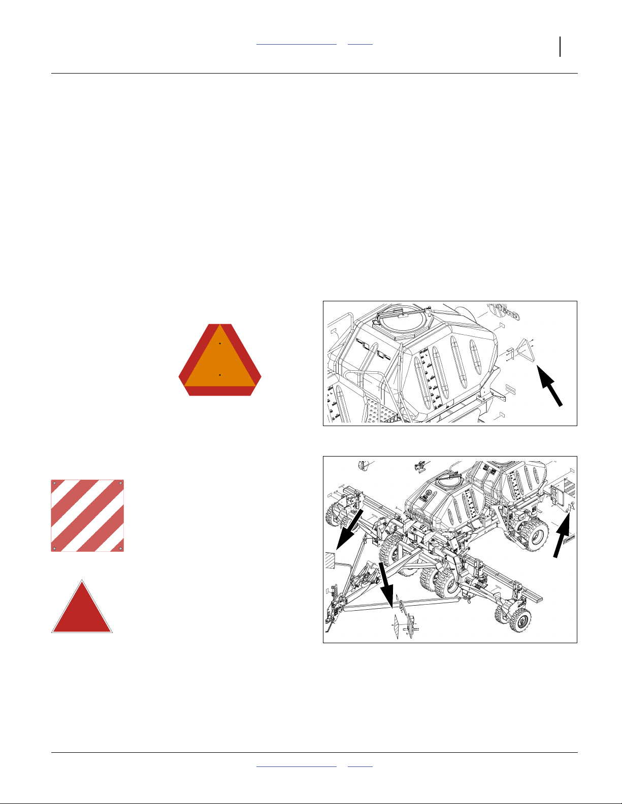
Reflectors: Fluorescent Panels
NTA907: 833-398C NTA3007: n/a
(North American models use
818-055C SMV reflectors,
838-266C red reflectors &
838-267C amber reflectors.)
Reflectors: Red Triangle
NTA907: 833-399C NTA3007: n/a
(North American models use
818-055C SMV reflectors,
838-266C red reflectors &
838-267C amber reflectors.)
panels: one each tongue draw bar,
panels and triangles: one each corner, rear mainframe;
4 panels and 2 triangles total
See “Transport Safety Information” on page 50.
32439
32422
2012-07-02 Table of Contents Index 166-371M
Page 16
12 NTA907 or NTA3007 Table of Contents Index Great Plains Manufacturing, Inc.
Reflectors: Amber
NTA907: 838-265C NTA3007: 838-265C
On outside end face, each wing opener tool bar,
on rear face, each wing main tool bar,
on outside face, mainframe sides ahead of ladder,
on outside face, rear caster mount weldment;
8 total.
See “Transport Safety Information” on page 50.
32422
Reflectors: Red
NTA907: n/a
(International models use
833-398C panels and
833-399C reflectors)
On upper rear corners of mainframe (below Daytime);
2 total
See “Transport Safety Information” on page 50.
NTA3007: 838-266C
Reflectors: Daytime
NTA907: n/a
(International models use
833-398C panels and
833-399C reflectors)
On upper rear corners of mainframe (above Red);
2 total
See “Transport Safety Information” on page 50.
NTA3007: 838-267C
Transport: Warning: Speed
NTA907: 848-398C NTA3007:
See 818-188C
32439
32439
32422
On front upper face of front hopper, and
on decal plate below rear beacon;
32377
2 total
See “Transport Safety Information” on page 50.
166-371M Table of Contents Index 2012-07-02
Page 17
Great Plains Manufacturing, Inc. Table of Contents Index Important Safety Information 13
Transport: Warning: Speed
NTA907:
See 848-398C
NTA3007: 818-188C
WARNING
EXCESSIVE SPEED HAZARD
To Prevent Serious Injury or Death:
Do Not exceed 20 mph maximum transport
speed. Loss of vehicle control and/or machine
can result.
On side of tongue near hitch;
one total
See “Transport Safety Information” on page 50.
Transport: Warning: Clearance
NTA907: 848-828C NTA3007: n/a
818-188C R v C
On front upper face on front hopper;
1 total
See “Transport Safety Information” on page 50.
Transport: Caution: Towing
NTA907: 848-512C NTA3007: 848-394C
On left side of tongue at hitch;
4 total
See “Transport Safety Information” on page 50.
Transport: Road/Field
NTA907: 848-393C NTA3007: 848-393C
32422
On mid-wing transport locks;
2 total
See “Transport Safety Information” on page 50.
2012-07-02 Table of Contents Index 166-371M
Page 18
14 NTA907 or NTA3007 Table of Contents Index Great Plains Manufacturing, Inc.
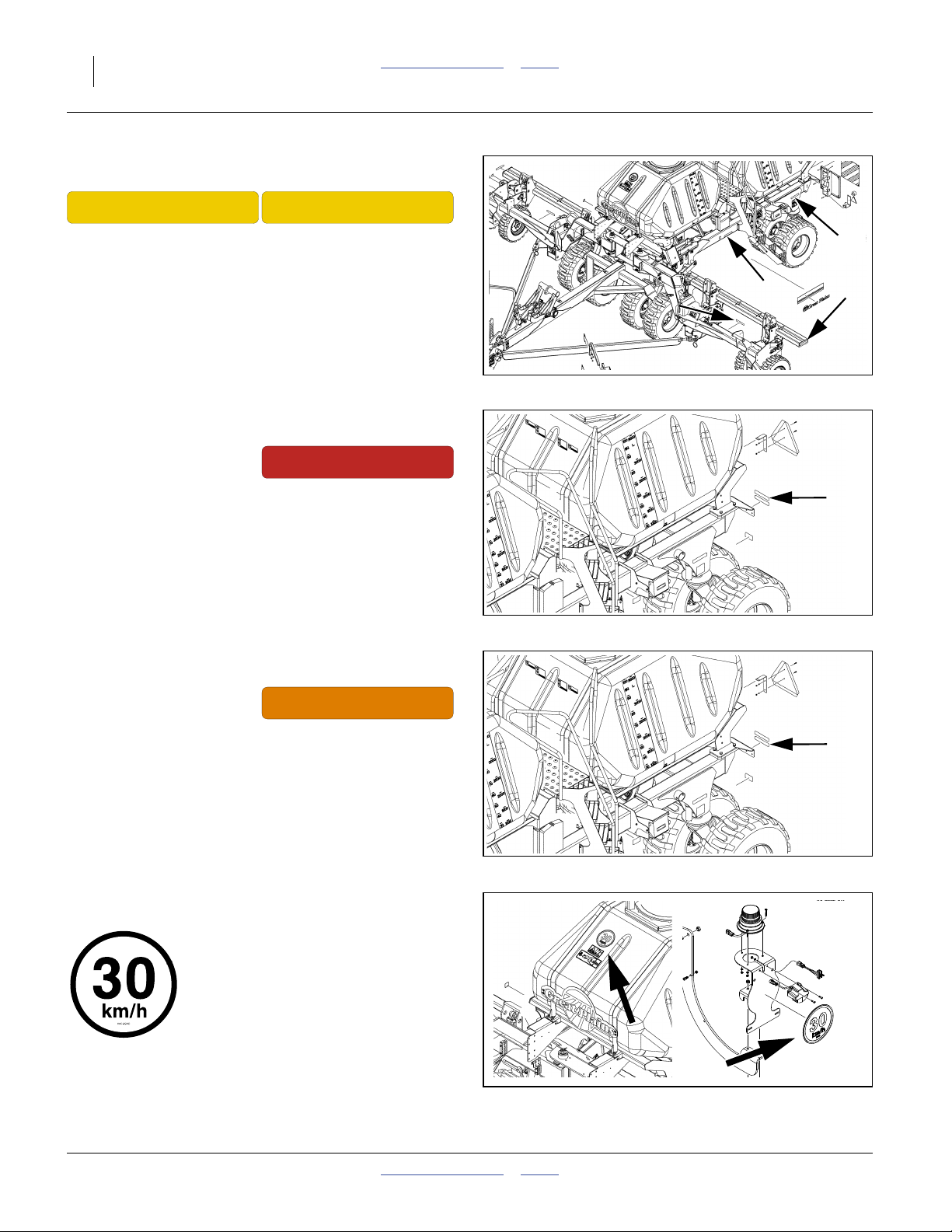
Transport: Road
NTA907: 848-834C NTA3007: 848-834C
On frame sides at centre section transport locks,
and on wing end transport locks;
4 total
See “Transport Safety Information” on page 50.
32422
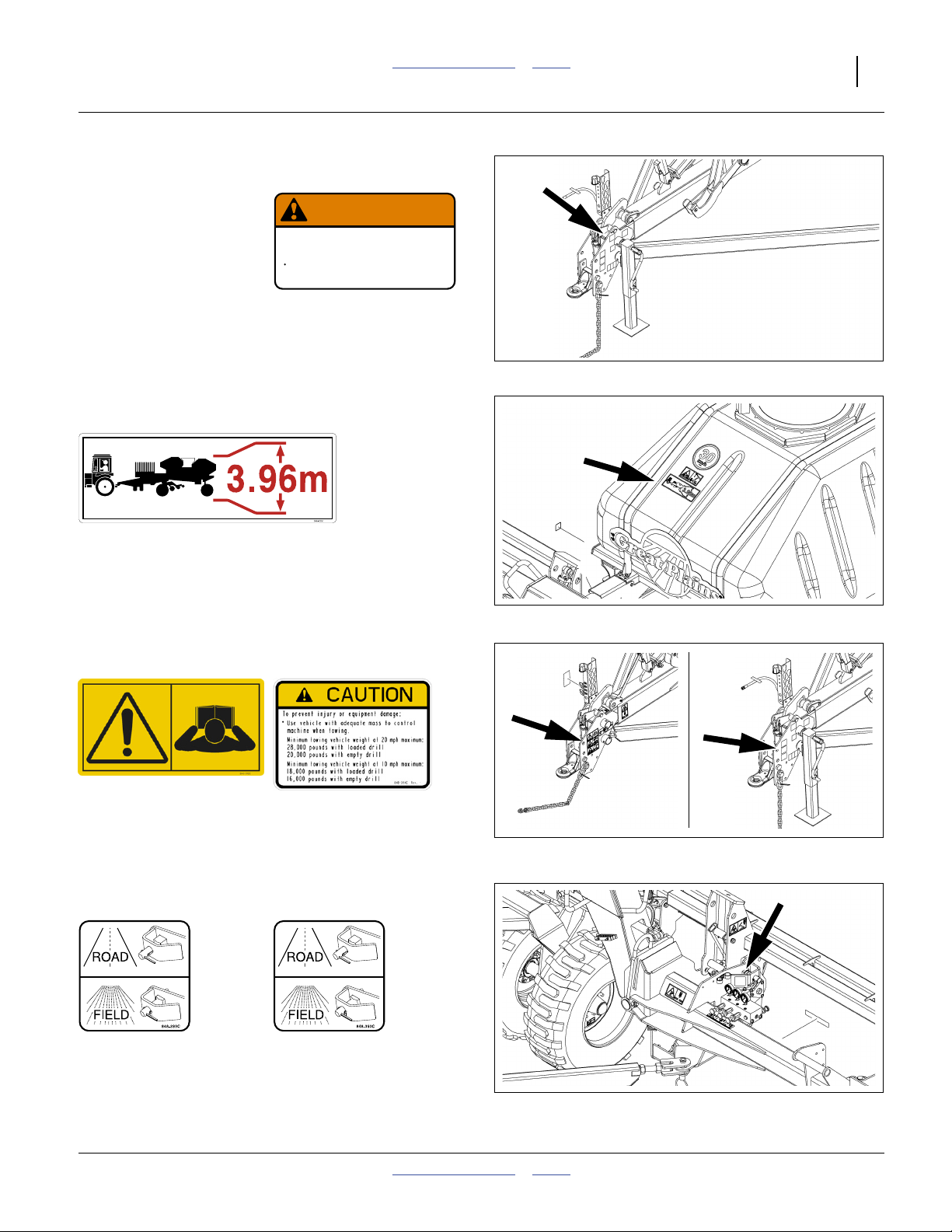
Transport: Field
NTA907: 848-837C NTA3007: 848-837C
On frame sides at centre section transport locks,
and on wing end transport locks;
4 total
See “Transport Safety Information” on page 50.
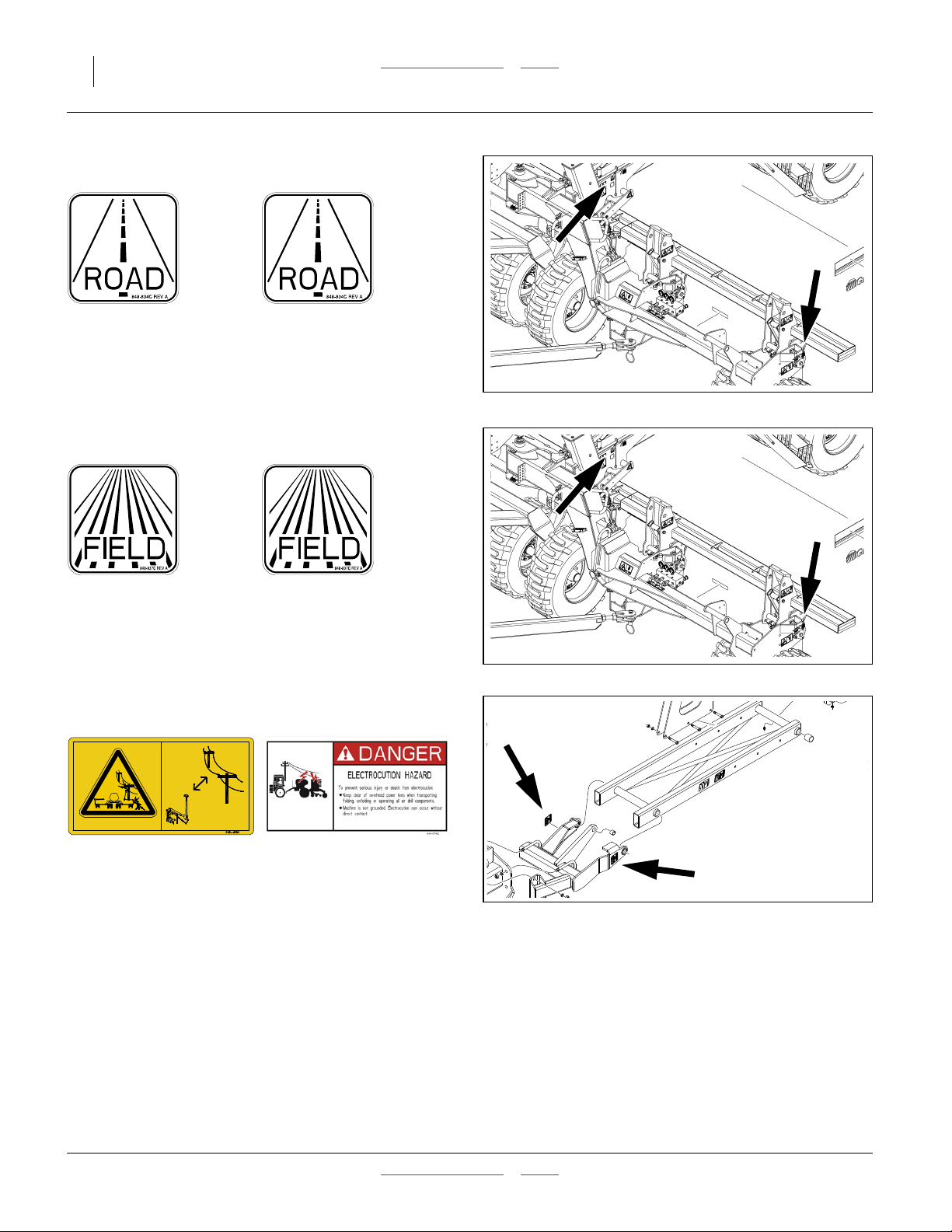
Danger: Electrocution, Marker (Option)
NTA907: 848-408C NTA3007: 848-574C
On marker mount weldment at end of wing;
4 total
See “Marker Safety Information” on page 73.
32422
29433
166-371M Table of Contents Index 2012-07-02
Page 19
Great Plains Manufacturing, Inc. Table of Contents Index Important Safety Information 15
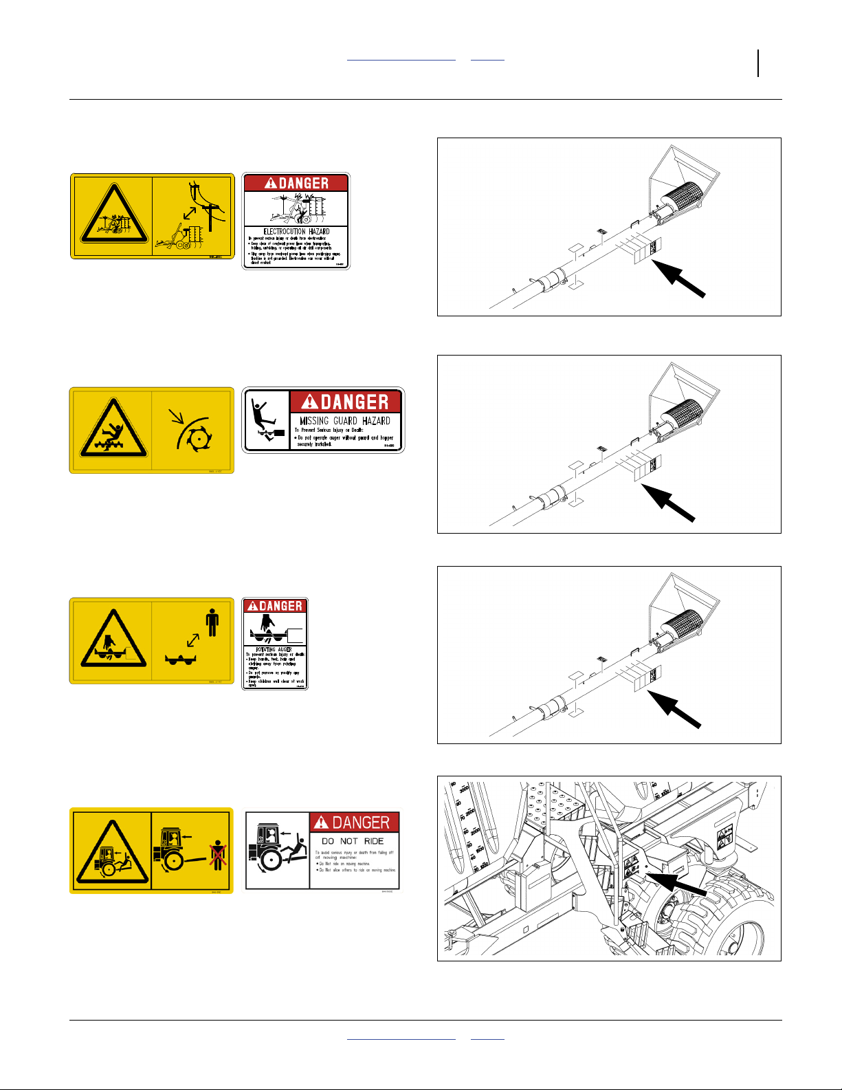
Danger: Electrocution, Auger (Option)
NTA907: 848-409C NTA3007: 818-627C
On auger tube near lower handles;
one total
32422
See “Auger Safety Information” on page 59.
Danger: Missing Guard (Option)
NTA907: 848-410C NTA3007: 818-633C
On auger tube nearest inlet;
1 total
See “Auger Safety Information” on page 59.
Danger: Rotating Auger (Option)
NTA907: 848-411C NTA3007: 818-634C
On auger tube near Missing Guard decal;
1 total
See “Auger Safety Information” on page 59.
Danger: Do Not Ride
NTA907: 848-511C NTA3007: 848-583C
32422
32422
On cart side frame, left of ladder;
1 total
32422
2012-07-02 Table of Contents Index 166-371M
Page 20
16 NTA907 or NTA3007 Table of Contents Index Great Plains Manufacturing, Inc.
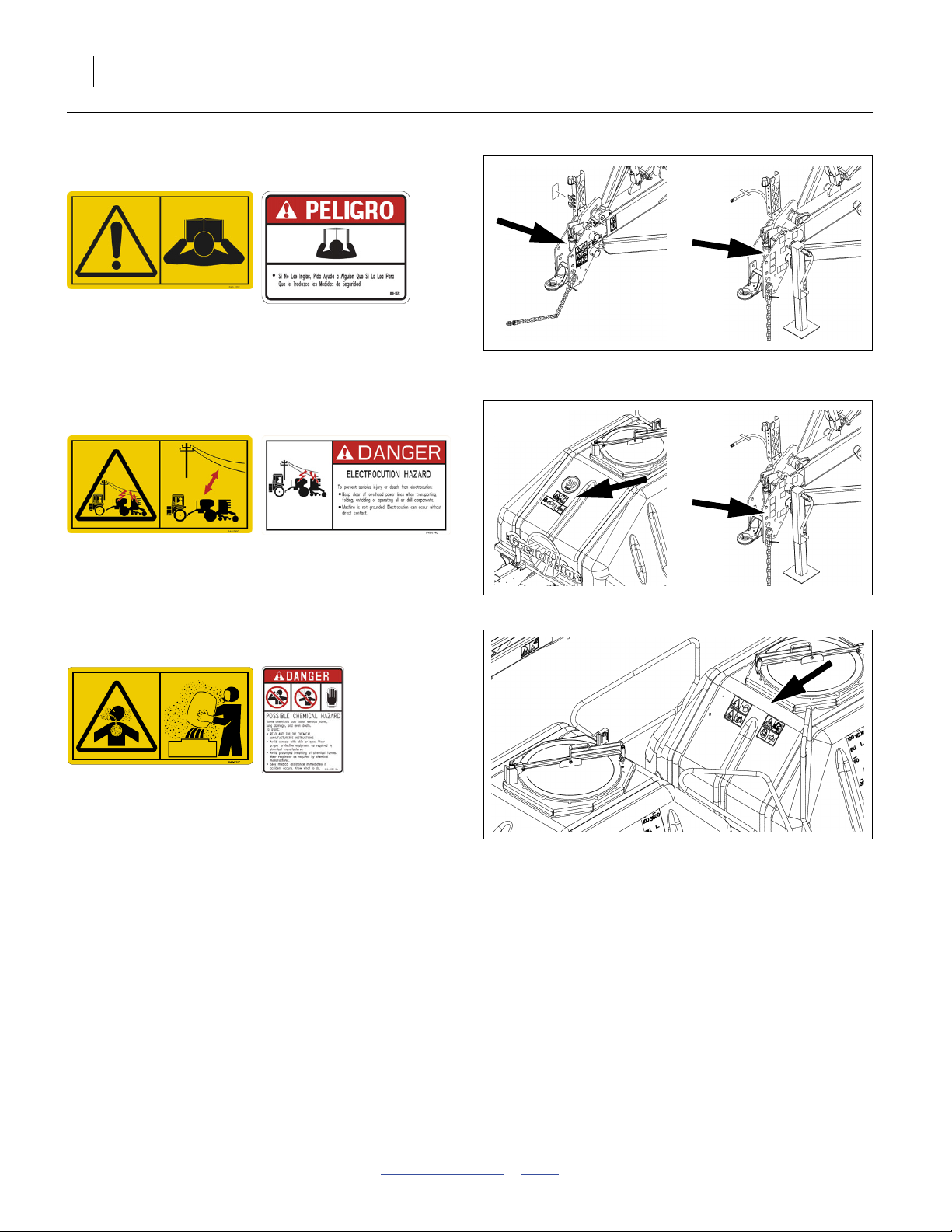
Danger: Read Manual
NTA907: 848-512C NTA3007: 818-557C
(818-557C Spanish text advises
readers to seek translation)
On left side of tongue near hitch;
32422
32439
1 each total
Danger: Electrocution
NTA907: 848-516C NTA3007: 848-574C
32422
NTA907: front upper face of front hopper,
NTA3007: left side of tongue near hitch;
1 total
Danger: Chemicals
NTA907: 848-520C NTA3007: 818-323C
On each hopper near lid, walkboard side;
2 total
See “Loading Material Safely” on page 65.
32439
32422
166-371M Table of Contents Index 2012-07-02
Page 21
Great Plains Manufacturing, Inc. Table of Contents Index Important Safety Information 17
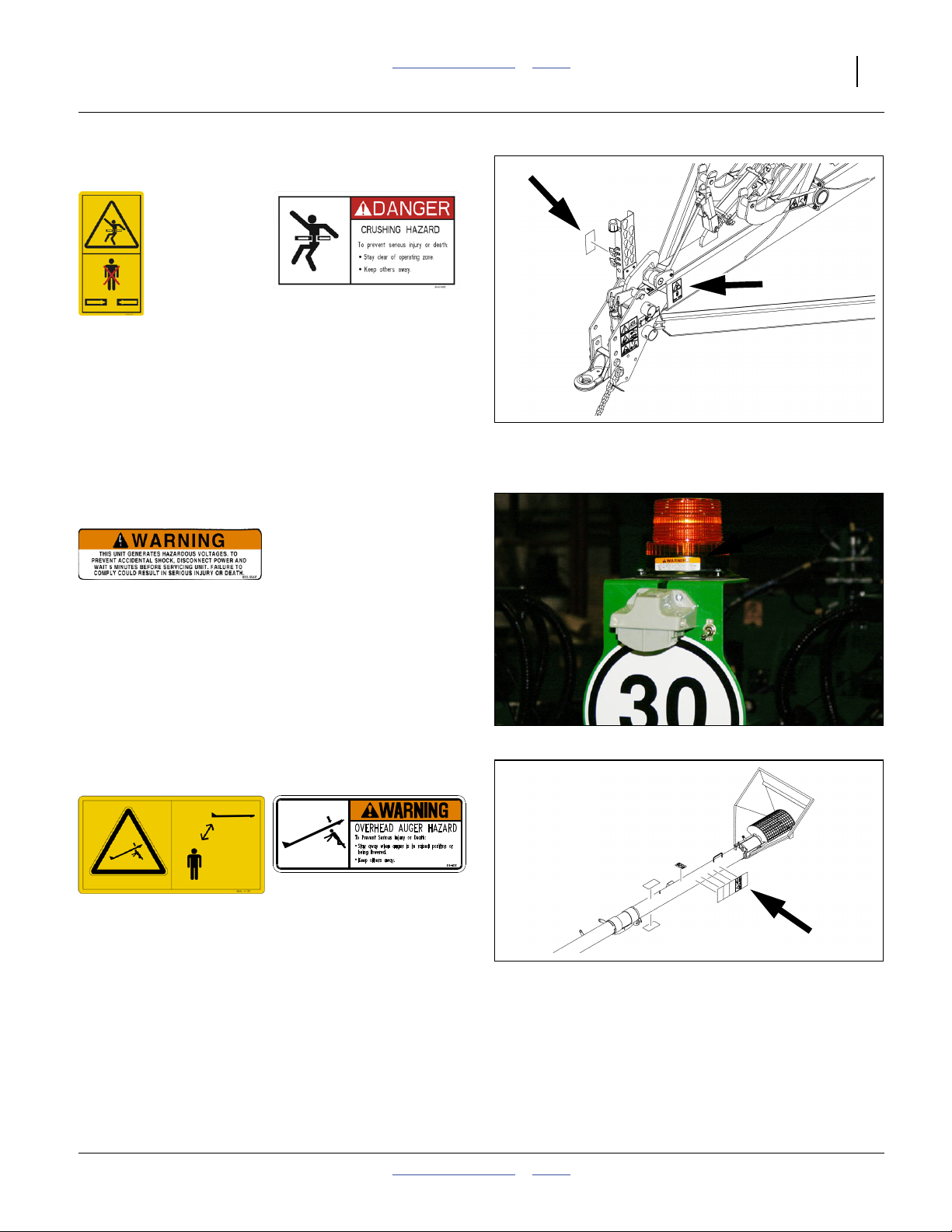
Danger: Hitch Crushing
NTA907: 848-523C NTA3007: 848-581C
On left side of hitch near behind pull bars;
2 total
See “Hitching Tractor to Drill” on page 27.
See “Unfolding Safety Information” on page 34.
See “Lowering/Raising Safety Information” on
32422
page 42.
See “Folding Safety Information” on page 44.
See “Down-Force Safety Information” on page 101.
Warning: Shock Hazard
NTA907: 833-563C NTA3007: n/a
On base of strobe beacon;
one total
This decal is not separately available. If missing or
damaged, replace entire 833-365C beacon unit.
See “Beacon Operation (NTA907 only)” on page 31
and “Beacon Maintenance (NTA907 only)” on
page 147.
Warning: Overhead Auger (Option)
NTA907: 848-413C NTA3007: 818-622C
On outside face of auger arm,
on each end of auger tube;
3 total
See “Remain Clear of Overhead Lines” on page 8 and
“Auger Safety Information” on page 59.
31234
32422
2012-07-02 Table of Contents Index 166-371M
Page 22
18 NTA907 or NTA3007 Table of Contents Index Great Plains Manufacturing, Inc.
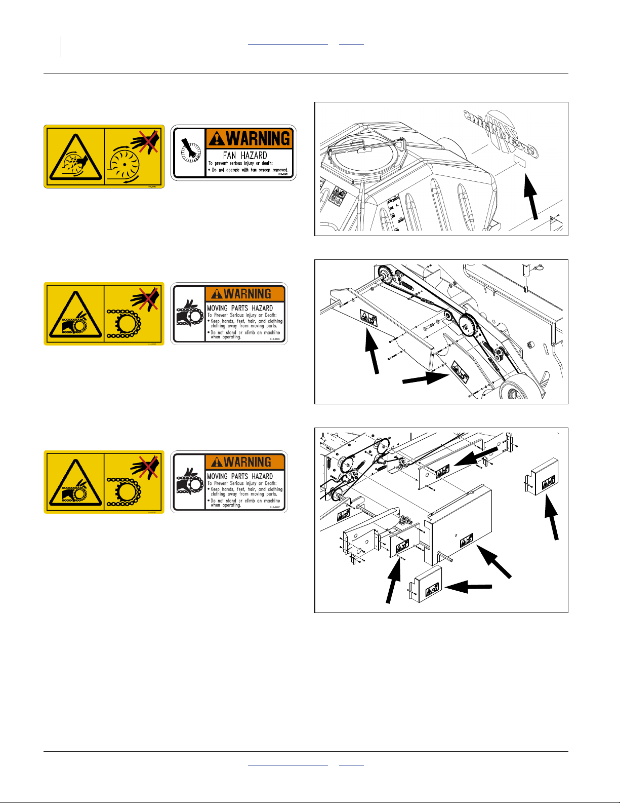
Warning: Fan Hazard
NTA907: 848-508C NTA3007: 818-632C
On rear main frame below fan screen cage;
one total
See “Fan Safety Information” on page 71.
32422
Warning: Moving Chain
NTA907: 848-509C NTA3007: 818-860C
On guards of contact to jackshaft drive system;
4 total
See “Calibration Crank Safety Information” on
page 69.
Warning: Moving Chain
NTA907: 848-509C NTA3007: 818-860C
On guards of main jackshaft to gearbox,
on guards of gearbox output drive systems, and
on meter box input guards;
5 total
See “Calibration Crank Safety Information” on
page 69.
32399
32397
166-371M Table of Contents Index 2012-07-02
Page 23
Great Plains Manufacturing, Inc. Table of Contents Index Important Safety Information 19
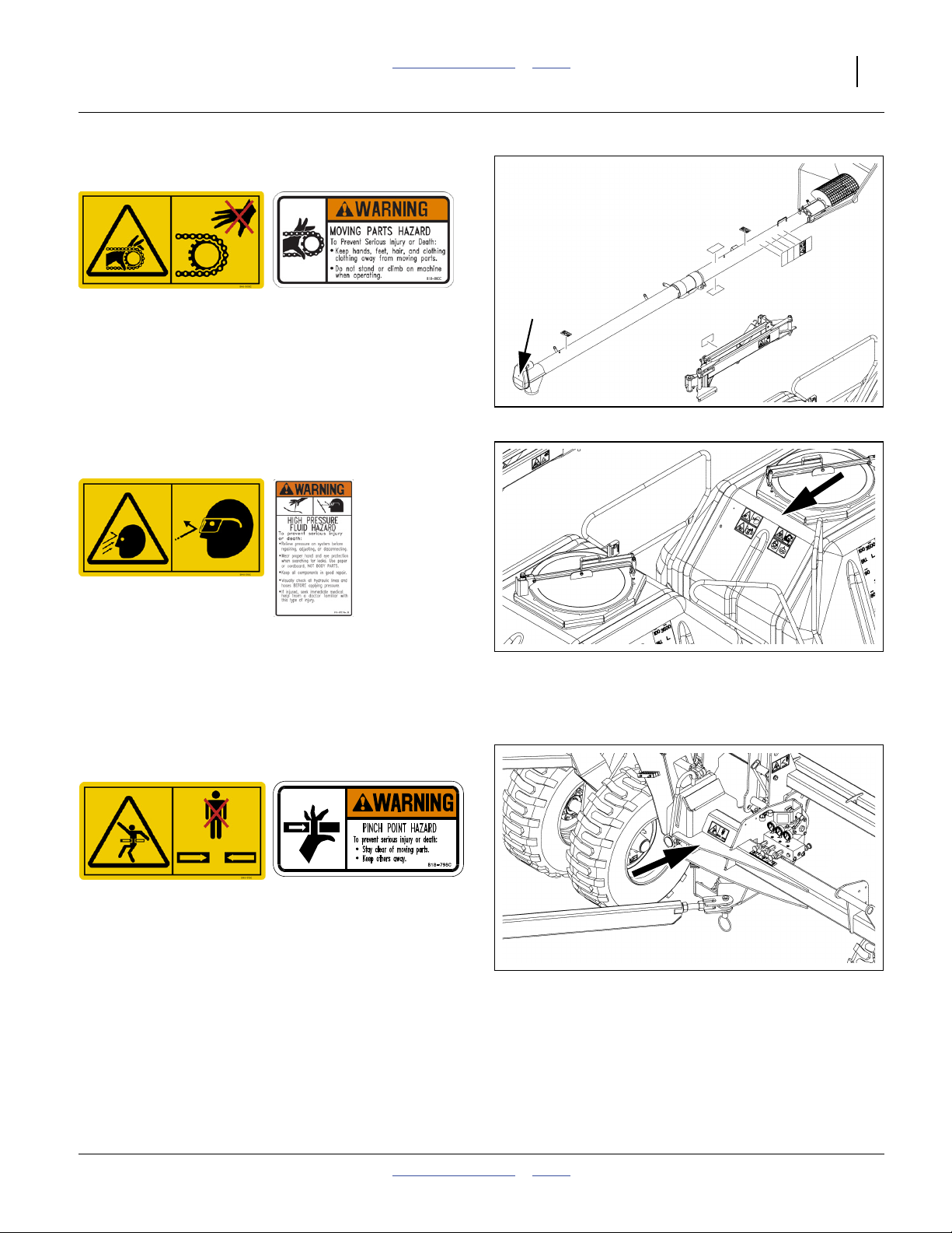
Warning: Moving Chain (Option)
NTA907: 848-509C NTA3007: 818-860C
On guard at auger hydraulic motor;
1 total
See “Auger Safety Information” on page 59.
32422
Warning: Wear Eye Protection
NTA907: 848-510 NTA3007: 818-437C
On each hopper near lid, walkboard side;
2 total
See “Hydraulic Hose Hook-Up” on page 28.
See “Hydraulic Maintenance Safety Information” on
page 128.
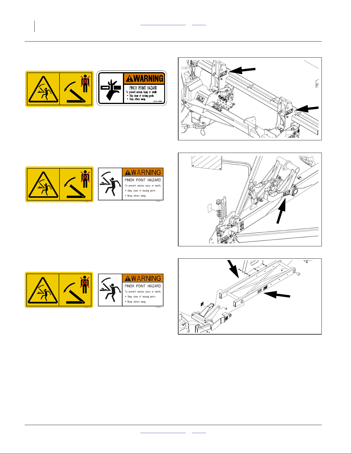
Warning: Pinch Point
NTA907: 848-513C NTA3007: 818-798C
On each wing weldment above pull bar attach point;
2 total
32422
32422
2012-07-02 Table of Contents Index 166-371M
Page 24
20 NTA907 or NTA3007 Table of Contents Index Great Plains Manufacturing, Inc.
Warning: Pinch Point
NTA907: 848-514C NTA3007: 818-798C
On outside faces of wing parallel arm mount weldments;
4 total
Warning: Pinch Point
NTA907: 848-514C NTA3007: 848-582C
On outside faces transport hook;
2 total
32422
Danger: Marker Pinch/Crush (Option)
NTA907: 848-514C NTA3007: 848-582C
On each side of inner marker arm or arm pivot;
4 total
See “Marker Safety Information” on page 73.
32422
29433
166-371M Table of Contents Index 2012-07-02
Page 25
Great Plains Manufacturing, Inc. Table of Contents Index Important Safety Information 21
Warning: Overhead Marker (Option)
NTA907: 848-515C NTA3007: 818-580C
On each side of inner marker arm or arm pivot;
4 total
See “Marker Safety Information” on page 73.
29433
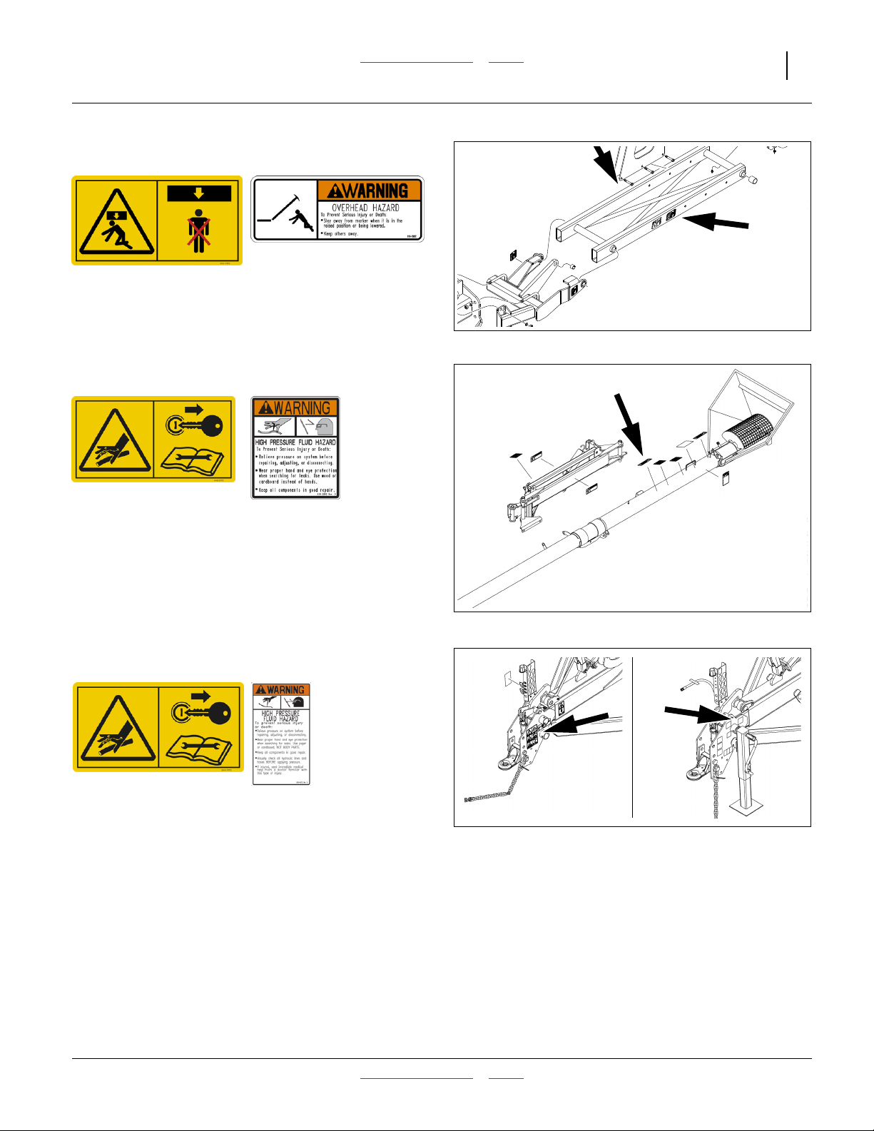
Warning: High Pressure Fluid (Option)
NTA907: 848-517C NTA3007: 818-339C
On (optional) auger near lower operating control;
1 total
See “Auger Safety Information” on page 59.
See “Fan Safety Information” on page 71.
See “Down-Force Safety Information” on page 101.
See “Weight Transfer Safety Information” on
page 107.
Warning: High Pressure Fluid
NTA907: 848-517C NTA3007: 818-437C
32439
On side of tongue at hitch;
one total
32422
32439
See “Hydraulic Hose Hook-Up” on page 28.
See “Hydraulic Maintenance Safety Information” on
page 128
2012-07-02 Table of Contents Index 166-371M
Page 26
22 NTA907 or NTA3007 Table of Contents Index Great Plains Manufacturing, Inc.
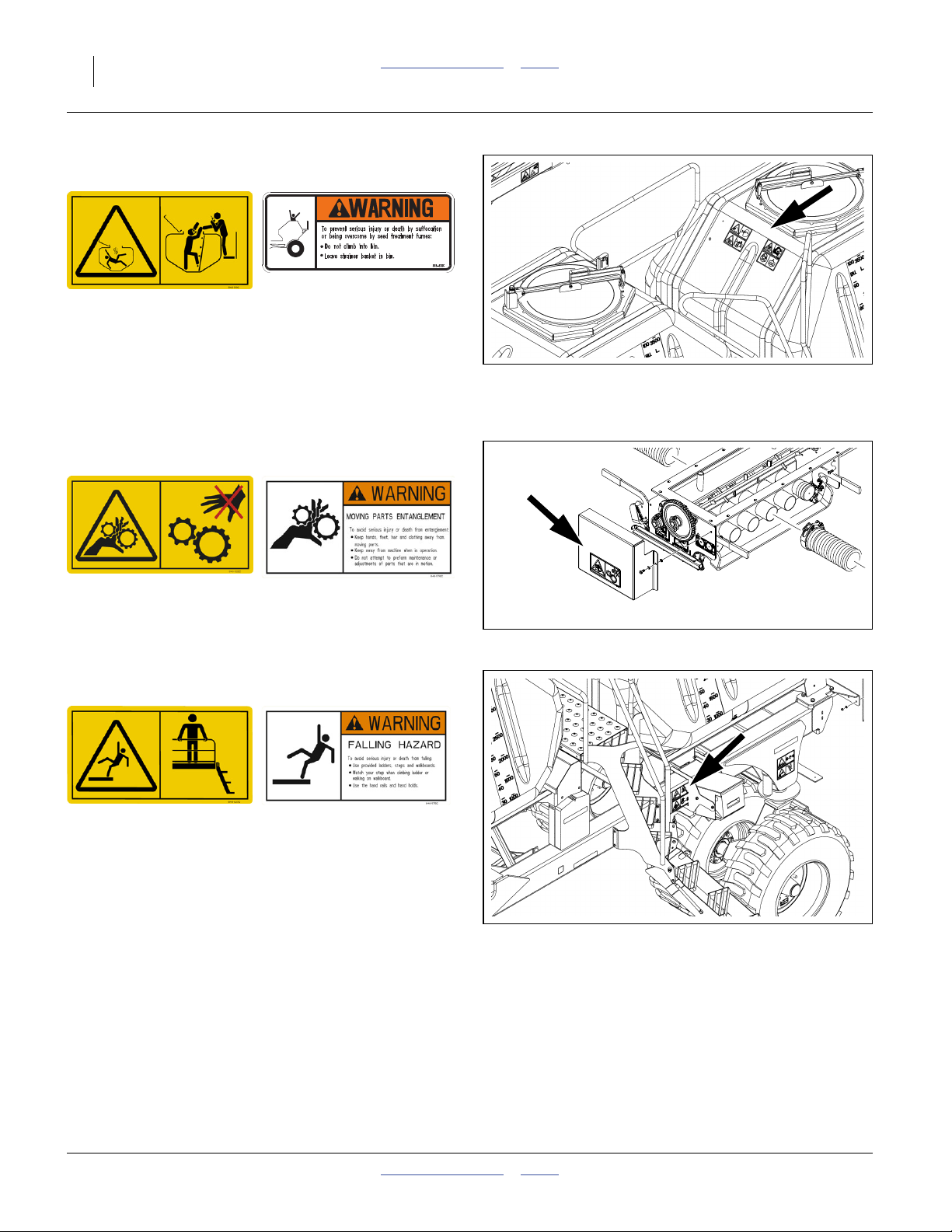
Warning: Confined Space
NTA907: 848-519C NTA3007: 818-628C
On each hopper near lid, walkboard side;
2 total
See “Hopper Lid Safety Information” on page 55.
See “Loading Material Safely” on page 65.
See “Material Clean-Out” on page 124.
Warning: Moving Gears
NTA907: 848-522C NTA3007: 848-576C
On bottom of hoppers above final Range gears;
1 or 2 total
See “Seed Meter Final Drive Range” on page 88.
32422
32414
Warning: Falling Hazard
NTA907: 848-527C NTA3007: 848-575C
On left side of mainframe near ladder;
1 total
See “Ladder Operations” on page 54.
32422
166-371M Table of Contents Index 2012-07-02
Page 27
Great Plains Manufacturing, Inc. Table of Contents Index Important Safety Information 23
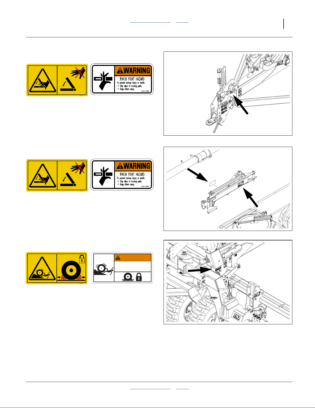
Warning: Pinch Point
NTA907: 848-531C NTA3007: 818-798C
Under tongue hook near hitch;
1 total
See “Unfolding Safety Information” on page 34.
32422
Warning: Pinch Point, Auger (Option)
NTA907: 848-531C NTA3007: 818-798C
On rear* faces of auger arms;
4 total
* When arms are fully extended.
Warning: Roll-Away
NTA907: 848-757C NTA3007: 818-760C
WARNING
ROLLING HAZARD
To avoid serious injury or death rom free ro ling machine
Use prov ded chock blocks to chock cart tires in
•
direction of grade when mach ne is parked
Chock both sides of wheel f grade is undetermined
•
On mainframe side above front transport tires;
2 total
See “Transporting the Air Drill” on page 50.
8 8-7 0C
2012-07-02 Table of Contents Index 166-371M
Page 28
24 NTA907 or NTA3007 Table of Contents Index Great Plains Manufacturing, Inc.
Warning: Unexpected Movement
NTA907: 848-838C NTA3007: 848-841C
CRUSHING HAZARD
To avod serious injury or death from crushing:
Mach ne moves rearward when fod ng w ngs forward
Stay away f om machne whi e folding and unfolding
On mainframe above rear casters;
2 total
See “Transporting the Air Drill” on page 50.
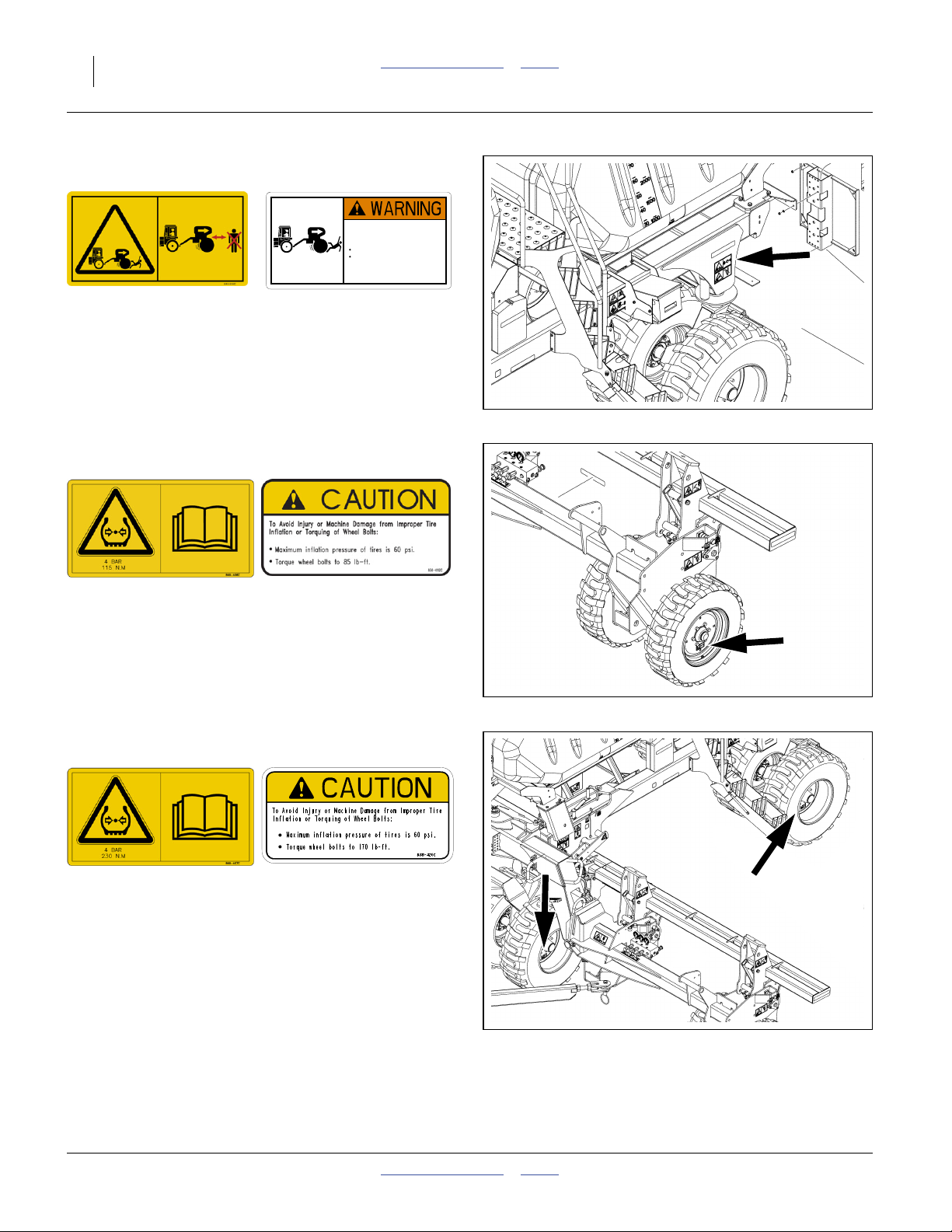
Caution: Tire Pressure and Torque
NTA907: 848-406C NTA3007: 838-092C
On outside of each wing gauge wheel tire;
4 total
See “Transport Safety Information” on page 50.
8 8 841C
32422
Caution: Tire Pressure and Torque
NTA907: 848-407C NTA3007: 838-426C
On outside of each transport wheel tire;
8 total
See “Transport Safety Information” on page 50.
166-371M Table of Contents Index 2012-07-02
Page 29
Great Plains Manufacturing, Inc. Table of Contents Index Important Safety Information 25
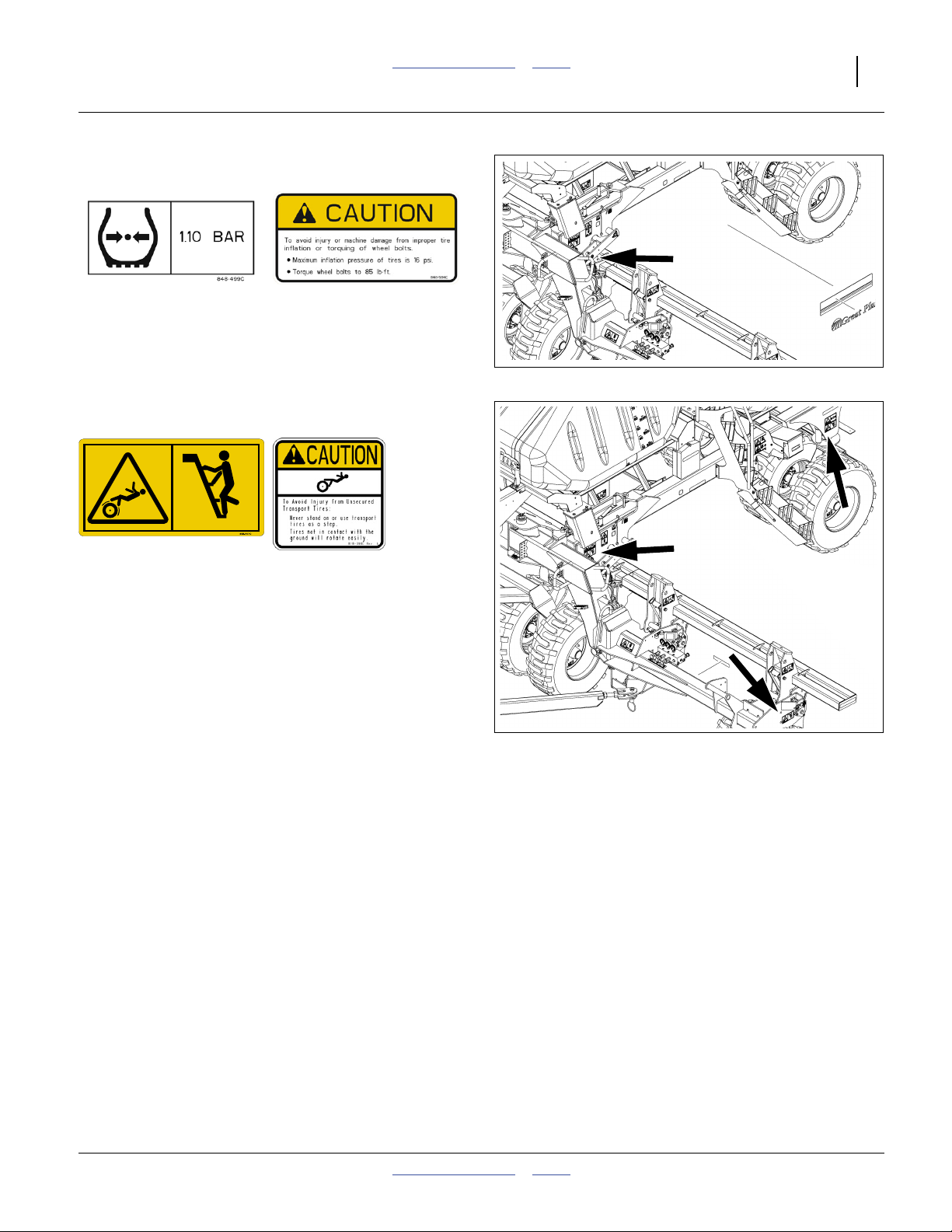
Caution: TyreTire Pressure and Torque
NTA907: 848-499C NTA3007: 848-584C
One each contact drive arm;
2 total
See “Transport Safety Information” on page 50.
32422
Caution: Tires Not A Step
NTA907: 848-507C NTA3007: 818-398C
On outside face of caster weldments,
on side face of mainframe above transport tires,
on outside face of wing gauge wheel weldments;
6 total
See “Unfolding Safety Information” on page 34.
See “Folding Safety Information” on page 44.
See “Down-Force Safety Information” on page 101.
See “Weight Transfer Safety Information” on
page 107.
32422
2012-07-02 Table of Contents Index 166-371M
Page 30

26 NTA907 or NTA3007 Table of Contents Index Great Plains Manufacturing, Inc.
Preparation and Setup
This section helps you prepare your tractor and NTA907
or NTA3007 for use, and covers seasonal tasks, and task
when the tractor/drill configuration changes.
Before using the NTA907 or NTA3007 in the field, you
must hitch the drill to a suitable tractor, inspect systems
and level the drill. Before using the drill for the first time,
and periodically thereafter, certain adjustments and
calibrations are required.
Initial Setup
See “Appendix B - Initial Setup” on page 183 and
“Appendix C - Option Installation” on page 185 for
pre-delivery items (normally completed by dealer), and
first-time/infrequent setup tasks, including:
❑ Install seed monitor console in tractor (page 183).
❑ Remove protective film from large highway
reflectors.
❑ Set marker extension (page 183) and speed.
Seasonal Setup
On initial delivery, use with a new tractor, and seasonally,
check and as necessary, complete these items before
continuing to the routine setup items:
❑ Bleed hydraulic system (page 128).
❑ Wing levelling and alignment (page 145).
❑ Speed sensor calibration (DICKEY-john® Air Cart
Control manual).
❑ Blow out entire air system to remove condensation.
Check air flow at each row, for evidence of plugging.
❑ De-grease exposed cylinder rods if so protected at
last storage.
Pre-Planting Setup
Complete this checklist before routine setup:
❑ Read and understand “Important Safety
Information”, pages 5 through 10.
❑ Check that all working parts are moving freely, bolts
are tight, and cotter pins are spread.
❑ Check that all grease fittings are in place and
lubricated. See “Lubrication and Scheduled
Maintenance” on page 148.
❑ Check that all safety decals and reflectors are
correctly located and legible. Replace if damaged.
See “Safety Decals” on page 11.
❑ Inflate tires to pressure recommended and tighten
wheel bolts as specified. See “Tire Inflation Chart”
on page 166.
166-371M Table of Contents Index 2012-07-02
Page 31

Great Plains Manufacturing, Inc. Table of Contents Index Preparation and Setup 27
Hitching Tractor to Drill
Crushing Hazard:
You may be severely injured or killed by being crushed
between the tractor and drill. Do not stand or place any part of
your body between drill and moving tractor. Stop tractor
engine and set tractor parking brake before attaching cables
and hoses.
1. Move the tractor to near hitching position.
2. Put the tractor in Park.
Set the tractor’s parking brake.
Shut down the tractor.
Refer to Figure 5 (which depicts the parking jack removed,
but not yet stored)
3. Adjust the NTA907 or NTA3007 hitch to match your
tractor draw bar height, using crank of tongue jack on
side of tongue.
Note: The precise height is not critical, as the NTA907 or
NTA3007 levelling is set at the mainframe and is
independent of tongue level.
4
Figure 5
Drill Hitched
29522
Hitch Failure Risk:
The hitch may be mounted inverted if necessary, but always
have two (2) bolts in two holes of both tongue and hitch. A
hitch failure could result in a serious accident and is likely to
result in implement and/or tractor damage.
4. Securely attach the safety chain to an anchor on a
tractor capable of pulling the NTA907 or NTA3007.
Refer to Figure 5 and Figure 6
5. Use crank to raise parking jack foot . Remove
3
pin and jack.
6. Move jack to upper stob . Rotate to horizontal.
Re-pin.
Equipment Damage Risk:
Store the parking jack on the upper stob in a horizontal
orientation, foot to rear. Using the lower stob, or any other
orientation, will result in jack and tongue damage.
7. Connect hydraulic hoses (page 28).
8. Connect brake hoses (option, page 29).
9. Connect electrical cables (page 30).
10. Remove and store main tongue parking stand.
1 2
4
4
3
Figure 6
Jack in Storage Location
1
2
32384
2012-07-02 Table of Contents Index 166-371M
Page 32

28 NTA907 or NTA3007 Table of Contents Index Great Plains Manufacturing, Inc.
Hydraulic Hose Hook-Up
High Pressure Fluid Hazard:
Escaping fluid under pressure can have sufficient pressure to
penetrate the skin causing serious injury. Avoid the hazard by
relieving pressure before disconnecting hydraulic lines. Use a
piece of paper or cardboard, NOT BODY PARTS, to check for
leaks. Wear protective gloves and safety glasses or goggles
when working with hydraulic systems. If an accident occurs,
seek immediate medical assistance from a physician familiar
with this type of injury.
Only trained personnel should work on system hydraulics!
Great Plains hydraulic hoses are colour coded to help
you hook-up hoses to your tractor outlets. Hoses that go
to the same remote valve have the same colour bands.
The fan pressure hose (black) must be connected to a
circuit capable of continuous flow at high volume.
The lift/down-pressure hose (blue) must be connected to
a circuit capable of continuous pressure.
Note: This implement is compatible only with tractors
having Closed Centre hydraulics.
Refer to Figure 7
To distinguish hoses on the same hydraulic circuit, refer
to handle symbols. The hose with an extended-cylinder
symbol feeds a cylinder base end. The hose with a
retracted-cylinder symbol feeds a cylinder rod end.
For the hydraulic fan, connect the hose with a retracted
cylinder symbol to the pressure side of the motor.
The fan motor further requires hook-up of a (third) case
drain line, which returns lubricating/cooling fluid.
marker hoses are provided on the cart even if markers
are not installed on the implement. See “Console
Installation” on page 183 prior to first hitching.
Figure 7
Hose Handles
Colour Hydraulic Function
Black Fan / Auger (Option)
Blue Opener Lift / Down-Pressure
Gray Weight Transfer
Green Fold / Tilt / Bout Marker (Option)
Yellow Transport Hook
“SUMP” Sump
“BRAKES” Hydraulic trailer brakes (Option)
31733
Protecting Fan Hydraulic Motor Seals
Low Pressure (Case) Drain Connection:
1. Attach case drain hose to low pressure drain
connection. See Notice at right.
2. Connect low pressure motor return hose, marked
“SUMP”, to a high volume low pressure return port.
The sump line is distinguished by a large
2.7 cm (1.06 inch) diameter) quick coupler.
3. Connect hydraulic hoses to tractor remotes.
166-371M Table of Contents Index 2012-07-02
Equipment Damage Risk:
Case Drain Hose must be attached first, prior to inlet and
return hoses being connected, to prevent damage to hydraulic
motor seals. The case drain has the smaller 6.4 mm (1⁄4inch)
I.D. hose and small, flat-face, low-seep connector. DO NOT
connect the case drain line to a power-beyond port.
Case Drain Hose must be detached last, to prevent damage to
the fan motor. To allow pressure relief during temperature
cycles, it is normal for this line to release small amounts of oil
even when stored with the connector elevated.
Page 33

Great Plains Manufacturing, Inc. Table of Contents Index Preparation and Setup 29
Brake Hook-Up (Option)
Two drill braking (trailer braking) systems are available:
• Dual-line air system (Figure 8), and
• Single-line hydraulic system (Figure 9).
In both systems, the tractor’s trailer brake remote port(s)
operate a hydraulic slave cylinder on the drill.
Tractor trailer braking systems are normally integrated
with the tractor brakes, and operate the trailer brakes
when tractor brakes are used during tractor movement.
Trailer brakes typically are not automatically engaged
when the tractor transmission is in Park, and may not be
engaged by any tractor Emergency Brake.
Braking Hazards:
Make sure the operator understands when drill brakes are
engaged and when they are released (record tractor behaviour
on page 52).
Also understand and implement tractor operational
restrictions when trailer brakes are used. For example, it is
generally necessary to inter-tie split brakes, and avoid
differential (steering braking) if trailer brakes are used.
Air Brake Hook-Up (Option)
Refer to Figure 10
1. Open petcock at reservoir tank. Drain any water
from tank. Close petcock.
Refer to Figure 11
2. Inspect gladhands before connecting. Clean
elastomer seal surfaces . Blow debris out of inlet
ports. Check screen condition.
3. Connect the “Brake”, “Service” or “Control” line first.
This line is Blue-coded.
1
2
Figure 8
Air Brake System
Figure 9
Hydraulic Brake System
29578
29588
1
This line operates the drill brakes.
Figure 10
29578
Air Brake Reservoir
2012-07-02 Table of Contents Index 166-371M
Page 34

30 NTA907 or NTA3007 Table of Contents Index Great Plains Manufacturing, Inc.
4. Connect the “Provision” or “Supply” line. This line is
Red-coded.
The Provision line charges a reservoir tank on the
drill. The Brake line operates a valve system which
meters tank air to the master cylinder on the drill.
Braking Hazard:
Do not use the NTA907 or NTA3007 with a “single-line” air
brake system. This drill is designed for transport speeds that
require an air brake system to be “dual-line”. A single-line
tractor system cannot charge the tank that powers the drill
brakes.
Roll-Away Hazard:
When unhitching, disconnect the red (control) line first. This
sets the brakes on the drill.
Hydraulic Brake Hook-Up (Option)
Refer to Figure 12
This is a single hydraulic line, connected to the tractor
“Brake” outlet.
The factory default connector is a3⁄4inch poppet-style
QD (Quick Disconnect). If this is incompatible with your
tractor, it may be replaced by a connector that mates to,
or can be adapted to:
3
⁄4inch male ORB (O-Ring Boss), or
3
⁄4inch female JIC (Joint Industry Conference, 37°
flare).
RED
Figure 11
Air Brake Connectors
Figure 12
Hydraulic Brake Connector
BLU
2
29646
29647
Electrical Hook-Up
Refer to Figure 13
Make sure tractor is shut down with accessory power off
before making connections.
1. Mate lighting connector to tractor outlet.
2. Mate monitor connector to tractor harness.
3. Mate any optional or after-market electrical
connectors.
Make connections prior to drill movement. Some drill
hydraulic circuits are under monitor control.
Figure 13
Lighting Connector (N.American)
and Monitor Connector
166-371M Table of Contents Index 2012-07-02
26467
27080
Page 35

Great Plains Manufacturing, Inc. Table of Contents Index Preparation and Setup 31
Beacon Operation (NTA907 only)
Refer to Figure 14
The flash strobe beacon and rear plate illumination lamp
may be disabled for field operations using a switch
below the beacon.
This switch does not control the brake/turn/running lights
at left and right rear.
See also “Beacon Maintenance (NTA907 only)” on
page 147.
1
1
Stow Wheel Chocks
• IMPROPER USE MAY RESULT IN PRODUCT FAILURE
• SELECT WHEEL CHOCK ACCORDING TO VEHICLE TYPE AND SIZE
• ALWAYS USE IN PAIRS AND ON FIRM SURFACES
• MULTIPLE PAIRS MAY BE REQUIRED IN EXTREME CONDITIONS
• CHOCK IN DIRECTION OF GRADE
• CHOCK BOTH SIDES OF WHEEL IF DIRECTION OF GRADE IS UNDETERMINED
• USE ONLY AFTER PARKING BRAKE IS APPLIED AND TESTED
• CENTER CHOCKS SNUGLY ANDSQUARELY AGAINST TREAD OF EACH WHEEL
• ALWAYS TEST CHOCKS TO INSURE THEY MEET REQUIREMENTS
• DO NOT DRIVE OVER WHEEL CHOCKS
1. Verify that the tractor transmission is in Park, and
that the tractor’s parking brake is set (per step 2).
Refer to Figure 15 and Figure 16
Two sets of wheel chocks (4 chocks total) are provided
to secure the drill when parked. These provide the most
safety when installed ahead and behind the outside front
transport tires.
When not in use, the chocks are stored in holders
mounted on the side frames. The chocks are held in
place by gravity when correctly stowed in the holders.
2. Remove the chocks from the wheel on one side.
WARNING
817-925C
1
2
Figure 14
Beacon Switch (Off)
2
1
Figure 15
Front Outside Wheels Chocked
32472
32375
Roll-Away Hazard:
If one chock is extremely difficult to remove, or the drill moves
significantly when the chock is removed, investigate the cause
before removing the chocks on the other side. If no tractor is
hitched, or the tractor is not securely parked, the drill could
roll away after chock removal, and cause an accident resulting
in death, serious injury and substantial property damage.
3. Store one chock in the bottom of a holder,
upside-right, tall end of chock toward frame.
4. Store the other chock in the top channel guides of
the holder, upside-down, short end toward frame.
5. Repeat step 2 through step 4 for the other side.
2012-07-02 Table of Contents Index 166-371M
2
Figure 16
Wheel Chocks Stowed
32376
1
Page 36

32 NTA907 or NTA3007 Table of Contents Index Great Plains Manufacturing, Inc.
Heights and Levelling
All frame sections must be at the correct height and level
to maintain even planting depth.
Periodic frame-levelling adjustments should not be
necessary. If you are having problems with uneven
depth, check drill levelness and follow these procedures.
1. Complete “Bleeding Hydraulics” on page 128.
2. Unfold the drill fully (page 34).
Set Tongue Height
Drill must be unfolded for this procedure.
Refer to Figure 17
Set the initial tongue height, tractor hitch, and changing
implement hitch configuration as necessary. Distance is
measured at top of tongue to ground level
If desired height cannot be attained with normal range of
hitch, hitch may be relocated in tongue bolt holes.
Always have two bolts in use, through two sets of hitch
holes and two sets of tongue holes.
Checking Drill Height
The drill is designed to operate with all sections of the
main tool bar nominally 76.2 cm (30 inch) above the
planting surface. The height of the centre section is not
routinely adjustable. Set planting depth with row unit
adjustments.
When lowering the drill for the first time on the planting
ground:
1. Completely lower the main tool bar. If necessary, first
lift off transport locks, remove and stow locks.
2. Set hitch to planting height.
3. Pull forward a meter or so (a few feet).
Note: Level frame in planting conditions.
Failure to do so may result in implement not
producing desired results.
49.5 cm
(19.5 in)
Figure 17
Initial Tongue Height
29523
Mis-Adjustment Risk:
Drill must be fully lowered to field position (with openers into
ground) and hitch height must be set before making
side-to-side adjustments.
Refer to Figure 18
4. Check tool bar height across drill. See page 145 for
further detail and adjustment.
Figure 18
Tool Bar Height Check
29519
Marker Setup
Prior to first use, check and adjust:
• See “Initial Marker Setup” on page 183.
166-371M Table of Contents Index 2012-07-02
Prior to each planting session, check and adjust:
• See “Marker Disc Adjustment” on page 115.
Page 37

Great Plains Manufacturing, Inc. Table of Contents Index 33
Operating Instructions
This section covers general operating procedures.
Experience, machine familiarity, and the following
information will lead to efficient operation and good
working habits. Always operate farm machinery with
safety in mind.
Pre-Start Checklist
Perform the following steps before transporting the
NTA907 or NTA3007 drill to the field.
High Pressure Fluid Hazard:
Escaping fluid under pressure can have sufficient pressure to
penetrate the skin. Check all hydraulic lines and fittings before
applying pressure. Fluid escaping from a very small hole can
be almost invisible. Use paper or cardboard, not body parts,
and wear heavy gloves to check for suspected leaks. If an
accident occurs, seek immediate medical assistance from a
physician familiar with this type of injury.
❑ Review “Important Safety Information” on page 5.
❑ Lubricate as indicated at “Lubrication and
Scheduled Maintenance” on page 148.
❑ Check all tires for proper inflation. See “Tire
Inflation Chart” on page 166.
❑ Check all bolts, pins, and fasteners. Torque as
shown in “Torque Values Chart” on page 167.
❑ Check drill for worn or damaged parts. Repair or
replace parts before going to the field.
❑ Check hydraulic hoses, fittings, and cylinders for
leaks. Repair or replace before going to the field.
29382
CFM Overview
The Control Function Module (CFM) is located below the
DICKEY-john® console terminal. The CFM controls a
bank of solenoid valves on the drill, in the
Fold/Tilt/Marker circuit.
On/Up opens the solenoid valve for the function.
Off/Down closes the solenoid valve for the function.
Control Function Module
Pre-Start Configuration
Figure 19
CFM Switch Operation
MASTER Fold Tilt Marker
Off (down) Off (down) Off (down) Off (down)
When MASTER is On, turn On only one function switch at a
time. To avoid unexpected movement of unintended drill
hydraulic components, no more than one of the Fold, Tilt or
Marker switches should ever be On at the same time.
Note: The CFM “MASTER” switch is the master for the
CFM only. It does not affect power to the monitor
terminal or other drill functions.
2012-07-02 Table of Contents Index 166-371M
Neutral Neutral Neutral Neutral
Hydraulic Circuit Operation
Lift
Fan,
Auger
Fold, Tilt,
Marker
29380
Transport
Hooks
Page 38

34 NTA907 or NTA3007 Table of Contents Index Great Plains Manufacturing, Inc.
Unfolding the Drill
Unfolding Safety Information
Roll-Away Hazard:
Unfold only on hard level ground. Allow ample room. Drill,
tractor, or both must be free to move during unfolding. On a
slope, roll away could occur, causing an accident resulting in
death, serious injury and substantial property damage.
Electrocution Hazard:
Keep clear of overhead power lines when unfolding, operating,
folding or transporting the drill. Machine is not grounded. At
higher voltages, electrocution can occur without direct
contact. Any line voltage present on implement, cart or tractor
can cause severe injury or death.
Pinch Point and Crushing Hazards:
Keep people away from the drill and tractor during unfolding.
The distance between the tractor and the seed structure
decreases by 3.2 m (7.5 feet) during unfolding. Drill, tractor,
or both will move during this operation. Wings will tilt down
and swing out. Risks include:
▲ Pinching or crushing at pivot points and at multiple sites in
pivoting assemblies. Stay clear of the wing sweep arcs.
Coulters and row openers are sharp.
▲ Crushing under lowering/moving wing wheels, under
moving transport wheels, under lowering wings or under
lowering openers.
Falling Hazard - Tires Not a Step:
Do not use tires as steps or platforms. Wing gauge wheel tires
are off the ground in transport lift. Front and rear main
transport tires may be lifted and free to spin on unlevel ground
and at some weight-transfer and row down-force settings.
CRUSHING HAZARD
To avoid serious injury or death from crushing:
Machine moves rearward when foldng wings forward.
Stay away from machine while folding and unfolding
848-841C
General Cautions:
▲ Unfold only with markers resting in transport cradles.
Do not unfold with openers lowered, or machine damage will
result.
▲ Unfold only if hydraulics are bled free of air and fully
charged with hydraulic oil.
166-371M Table of Contents Index 2012-07-02
Page 39

Great Plains Manufacturing, Inc. Table of Contents Index Operating Instructions 35
Unfold: Summary of Steps
Follow the detailed instructions in step 1 through step 14
until this is a familiar operation.
❑ Check markers, auger and ladder stowed (below).
❑ Set mainframe transport locks to FIELD (below).
❑ Release transport hook (page 36).
❑ Set tractor for unfold (page 36).
❑ Unfold wings (page 37).
❑ Check openers raised (page 41).
❑ Set outer wing locks to FIELD (page 39).
❑ Tilt down wings (page 39).
Unfold: Check Drill Configuration
Wings can collide with a deployed auger or ladder.
1. Make sure:
ladder (page 54),
auger (page 64) and
markers (page 73)
are secured in their transport positions before
unfolding.
2. Move to level ground.
Pre-Unfold: Hydraulic Circuit Operation
Fan,
Lift
Neutral Neutral Neutral Neutral
Auger
Fold, Tilt,
Marker
Transport
Hooks
Sudden Implement Movement Risk:
Always have hydraulic levers in Neutral when operating CFM
switches.
3. Set/check that CFM switches (see page 33) are all
Off and hydraulic circuits are all in Neutral.
Shut off tractor.
Unfold: Two Mainframe Locks: ROAD to FIELD
Refer to Figure 21
4. On both sides of the mainframe, pull the wire handle
outward and move to rear slot. This allows hooks
(not shown) to move forward and enables lowering of
the centre section openers (after unfold). If the
openers are not fully raised, the hooks may not move
immediately. Tension in the wire loop handle is
expected in that case.
Note: Lowering the openers is not part of the unfold
operation, but these locks are easier to reach
before the wings are unfolded.
ROAD
Figure 20
CFM All Off
FIELD
Figure 21
Centre Locks: ROAD to FIELD
29380
32388
2012-07-02 Table of Contents Index 166-371M
Page 40

36 NTA907 or NTA3007 Table of Contents Index Great Plains Manufacturing, Inc.
Unfold: Release Transport Hook
5. Extend the Transport Hook circuit.
Set it to Neutral.
Note: Transport hook is on a dedicated circuit.
Refer to Figure 22 (which depicts the transport hook unlocked
and disengaged)
6. Pull the lift lock handle forward to disengage the
transport hook lock channel . Pull the handle until
the lock channel rests at fully open.
1
2
Un-Weight: Hydraulic Circuit Operation
Fan,
Lift
Neutral Neutral Neutral Extend
Auger
Fold, Tilt,
Marker
Transport
Hooks
2
1
7. Have everyone move clear of the drill. Retract the
transport hook cylinder:
Refer to Figure 23
8. Observe wings and gauge wheels lowering during
un-hook.
9. When the cylinder is fully retracted, set the transport
hook circuit to Neutral.
Unfold: Set Tractor
10. To allow tractor movement:
set steering straight ahead,
put tractor transmission in neutral and
release tractor parking brake.
Figure 22
Transport Hook Lock Channel
Un-Hook: Hydraulic Circuit Operation
Fan,
Lift
Neutral Neutral Neutral Retract
Auger
Wing Movement During Un-Hook
Fold, Tilt,
Figure 23
Transport
Marker
Un-Hook: Hydraulic Circuit Operation
Fan,
Lift
Neutral Neutral Neutral Neutral
Note: If tractor movement is not desired:
put tractor transmission in Park,
set tractor parking brake, and
release drill brakes (if drill is brake-equipped, and
tractor can separately control drill brakes).
Auger
Fold, Tilt,
Marker
Transport
32385
Hooks
29389
Hooks
Do not set tractor parking brake if tractor parking
brake actuates trailer (“service”) brake system.
166-371M Table of Contents Index 2012-07-02
Page 41

Great Plains Manufacturing, Inc. Table of Contents Index Operating Instructions 37
Unfold: Unfold Wings
Drill check, un-hook and tractor setup (step 1 through
step 10 starting on page 45) must be completed before
performing the next steps.
Refer to Figure 24
11. On the CFM switch, enabled unfolding with MASTER
and Fold set on.
Figure 24
CFM Unfold Enable
29380
Crushing Hazard:
Clear everyone from around the drill and tractor. The drill or
the tractor, or both, must move during unfold.
12. Unfold the wings (now tilted down) by retracting the
fold cylinders.
Refer to Figure 25 (depicting an unfold with both tractor and
drill free to move - notice how the length of the drill shortens,
and that it has pulled the tractor toward the drill)
Observe the unfolding. It is not complete until the tongue
lock at the hitch engages the roller on the telescoping
centre tongue tube.
Machine Damage Risk:
Do not tilt down or lower openers while any drill folding
operations are under way or partially complete.
Unfold Wings: Hydraulic Circuit Operation
Fan,
Lift
Neutral Neutral Retract Neutral
Auger
Fold, Tilt,
Marker
Transport
Hooks
Figure 25
Wing Unfold Progression
32409
32408
32407
Refer to Figure 26
13. Continue unfolding until tongue lock hook engages
roller on telescoping tongue tube. it may be
necessary to back up the tractor for full engagement.
Machine Damage Risk:
Do not operate drill when unfolded unless tongue lock is
engaged.
Figure 26
29393
Tongue Hook Engaged
2012-07-02 Table of Contents Index 166-371M
Page 42

38 NTA907 or NTA3007 Table of Contents Index Great Plains Manufacturing, Inc.
14. When the wings are fully unfolded, stop fold cylinder
retraction, and hold wings open with Neutral.
15. Disable the Fold solenoid valve.
Unfold: Free Wing Transport Locks
Step 16 may not be necessary on a recently folded drill.
16. Relieve any weight on the wing tip locks.
Select Tilt operation:
Briefly perform a tilt-up.
Unfold Complete: Circuit Operation
Fan,
Lift
Neutral Neutral Neutral Neutral
Auger
CFM Unfold Complete
CFM Tilt Enable for Un-Weight
Fold, Tilt,
Figure 27
Figure 28
Marker
Transport
Hooks
29380
29380
Tilt Un-Weight: Hydraulic Circuit Operation
Fan,
Lift
Neutral Neutral
Auger
Fold, Tilt,
Marker
Retract
then
Neutral
Transport
Hooks
Neutral
17. Shut off tractor.
166-371M Table of Contents Index 2012-07-02
Page 43

Great Plains Manufacturing, Inc. Table of Contents Index Operating Instructions 39
Unfold: Two Wing End Locks: ROAD to FIELD
Refer to Figure 29 and Figure 30 (Figure 30 is shown tilted
down for clarity - perform this lock change while the openers
are tilted up)
18. Reverse the catching direction of the wing end locks.
Pull the wire handle outward. Rotate the pin
180 degrees, placing the angled surface forward and
the longer side of the tip to the rear. This allows the
plate to push the pin aside during tilt-down, and
catches the plate for down-pressure regulation in the
field.
Note: Mid-Wing Locks: As-Is
The mid-wing locks require no attention during
unfold.
1
Unfold: Tilt-Down
The transport hook and transport locks must be released
(step 5 through step 18 starting on page 36) before
performing the next steps.
Refer to Figure 31
19. On the CFM switch, enable Tilt with MASTER and
Tilt on.
20. Extend the Fold/Tilt/Marker circuit.
Figure 29
Wing End Lock Location (LH)
ROAD
Figure 30
Wing End Lock : ROAD to FIELD
Figure 31
CFM Tilt Enable for Tilt-Down
FIELD
1
Tilt-Down: Hydraulic Circuit Operation
32412
32389
29380
Fan,
Lift
Neutral Neutral Extend Neutral
2012-07-02 Table of Contents Index 166-371M
Auger
Fold, Tilt,
Marker
Transport
Hooks
Page 44

40 NTA907 or NTA3007 Table of Contents Index Great Plains Manufacturing, Inc.
Refer to Figure 32
21. Observe the wings during tilt down.
22. When the wings are fully tilted out and down, set
circuit to Neutral.
Figure 32
Tilt Down Progression
32407
32406
32405
Tilt-Down Complete: Circuit Operation
Fan,
Lift
Neutral Neutral Neutral Neutral
Auger
Fold, Tilt,
Marker
Transport
Hooks
166-371M Table of Contents Index 2012-07-02
Page 45

Great Plains Manufacturing, Inc. Table of Contents Index Operating Instructions 41
Unfold: Check That Openers are Raised
Refer to Figure 33
23. When tilt-down is complete, check that no wing
openers are too close to, or touching the ground.
Review “Lowering/Raising Safety Information” on page 42.
Ground Contact Risk:
Openers must be in the raised position before unfolding. If the
drill has been stored on a hillside for an extended period, there
is some chance that openers on one wing may not be fully
raised.
Figure 33
Tilt-Down Complete - Check Raised
32405
24. If wing openers are too low on one or both sides,
raise them before unfolding, by extending the lift
cylinders.
25. When vertical movement has stopped (and the
centre section may stop last), hold the openers in the
raised position by setting circuit to Neutral.
26. If no markers are installed, you may also set the
MASTER switch to Off. The CFM is not used in the
field unless markers are installed.
Tilt-Down Complete: Circuit Operation
Fan,
Lift
Extend Neutral Neutral Neutral
Auger
Fold, Tilt,
Marker
Transport
Hooks
Tilt-Down Complete: Circuit Operation
Fan,
Lift
Neutral Neutral Neutral Neutral
Auger
CFM Unfold Complete
Fold, Tilt,
Figure 34
Marker
Transport
Hooks
29380
2012-07-02 Table of Contents Index 166-371M
Page 46

42 NTA907 or NTA3007 Table of Contents Index Great Plains Manufacturing, Inc.
Lowering and Raising Drill
Lowering/Raising Safety Information
Crushing Hazard During Lowering:
Stay clear of wings and openers during raising and lowering.
Opener sections, in addition to being extremely heavy, are
forced down with hydraulic pressure. Coulter and opener discs
are sharp. During lowering, openers will cut or crush anything
beneath them, and can cause death or serious injury.
Crushing Hazard While Raised:
Fully lower openers when working above or beside them.
Use blocking or stands when working under openers.
Raised wing openers are held up only by hydraulic pressure.
With wings tilted down, openers will slowly lower over time.
They may lower more rapidly if the hydraulic system is
damaged. They will lower rapidly if the hydraulics fail, or if
the lift circuit is set to Float or Retract.
Ground Contact Risk:
Do not lower openers while any drill folding operations are
under way or partially complete.
Note: The lift (raise/lower) circuit is also the hydraulic
down-pressure circuit. Hydraulic down-pressure
only functions as intended if the transport locks are
set to FIELD (page 39).
Lowering
1. Unfold drill before lowering (page 34).
2. Make sure all persons are clear of opener sections.
3. Actuate dedicated lift circuit (normally Extend).
4. If down-pressure has been adjusted (page 101),
leave the circuit in Extend.
If down-pressure has not been adjusted, or if not
planting immediately, set the circuit to Neutral.
Lower: Hydraulic Circuit Operation
Fan,
Lift
Extend - Neutral Neutral
Note: After unfolding, the centre section openers may be
resting in the transport hooks, despite the lock
handle being set to FIELD. You may need to raise
the openers before lowering them, to allow the
spring-loaded hooks to swing to FIELD position.
Auger
Fold, Tilt,
Marker
Transport
Hooks
166-371M Table of Contents Index 2012-07-02
Page 47

Great Plains Manufacturing, Inc. Table of Contents Index Operating Instructions 43
Raising
Ground Contact Risk:
The drill must be raised for folding and unfolding.
Opener Damage Risk:
Always raise the drill for any reverse/backing operations.
1. Make sure all persons are clear of opener sections.
2. Actuate dedicated lift circuit (normally Retract).
3. Retract until all sections are raised. Centre section
tends to lift later than wings.
4. Set circuit to Neutral to temporarily hold openers
raised.
Lift: Hydraulic Circuit Operation
Fan,
Lift
Retract - Neutral Neutral
On tractors with electronic timer controls for hydraulic
circuits, lift timers must be set to no more than 2 seconds
longer than needed to fully raise the drill.
Do Not Set for Continuous Mode.
Auger
Fold, Tilt,
Marker
Transport
Hooks
End Lift: Hydraulic Circuit Operation
Fan,
Lift
Neutral - Neutral Neutral
Auger
Fold, Tilt,
Marker
Transport
Hooks
2012-07-02 Table of Contents Index 166-371M
Page 48

44 NTA907 or NTA3007 Table of Contents Index Great Plains Manufacturing, Inc.
Folding the Drill
Fold the NTA907 or NTA3007 drill for moves between
fields and over public roads, and for storage.
Folding Safety Information
Roll-Away Hazard:
Fold only on hard level ground. Allow ample room. Drill,
tractor, or both must be free to move during folding. On a
slope, roll away could occur, causing an accident resulting in
death, serious injury and substantial property damage.
Pinch Point and Crushing Hazards:
Keep people away from the drill and tractor during folding.
The distance between the tractor and the seed structure
increases by 3.2m (7.5ft) during folding. Drill, tractor, or both
will move during this operation. Wings will swing forward.
Risks include:
▲ Pinching or crushing at pivot points and at multiple sites in
pivoting assemblies. Stay clear of the wing sweep arcs.
Coulters and row openers are sharp.
▲ Anything in between pull-bars and tongue, or in between
wing tool bar and tongue, will be crushed.
▲ Anyone or anything in front of or behind tractor or drill
could be run over.
CRUSHING HAZARD
To avod serious injury or death from crushing:
Mach ne moves rearward when fod ng w ngs forward
Stay away f om machne whi e folding and unfolding
8 8 841C
Transport and Overhead Hazard:
Use wing locks (FIELD to ROAD). Use the transport hook
cylinder lock channel. If a hydraulic failure occurs, or
hydraulic levers are moved, unlocked wings could fall
suddenly causing a major road accident, or crushing anything
near the wings, resulting in death or serious injury, and
property damage.
Falling Hazard - Tires Not a Step:
Do not use tires as steps or platforms. Wing gauge wheel tires
are off the ground in transport lift.
General Cautions:
▲ Fold only with markers resting in transport cradles.
Machine Damage Risk:
Do not fold with openers lowered.
▲ Fold only if hydraulics are bled free of air and fully charged
with hydraulic oil.
166-371M Table of Contents Index 2012-07-02
Page 49

Great Plains Manufacturing, Inc. Table of Contents Index Operating Instructions 45
Fold: Summary of Steps
Follow the detailed instructions in step 1 through step 23
until this is a familiar operation.
❑ Check markers, auger and ladder stowed (below).
❑ Raise openers (page 43).
❑ Preset transport hook (below)
❑ Set wing transport locks to ROAD (below).
❑ Tilt up wings (page 46).
❑ Set tractor for fold (page 47).
❑ Fold wings (page 44).
❑ Engage transport hook (page 48)
❑ Set mainframe transport locks to ROAD (page 49).
Fold: Check Drill Configuration
1. Make sure
markers (page 73),
auger (page 64) and
ladder (page 54)
are secured in transport positions before unfolding.
2. Raise openers (page 43).
3. Move to level ground.
Fold: Preset Transport Hook
Refer to Figure 35
4. Check that transport hooks are fully lowered
(cylinder fully retracted). If not, Retract hook circuit
as needed.
5. Tilt transport hook look channel rearward until it rests
on the hook cylinder. This prepares the lock to
engage automatically when the hook is raised.
Fold: Set Wing Locks to ROAD
Fold: Two Mid-Wing Locks to ROAD
Refer to Figure 36
6. Pull the pin outward. Swing the pivoting foot inward
and use it to prop the pin in the retracted position.
This allows the edge of the plate to pass the pin
during tilt-up.
Note: A weldment on the plate resets the pin for
automatic FIELD configuration at next tilt-down.
FIELD
Figure 35
Prepare Transport Hook for Fold
ROAD
Figure 36
Mid-Wing Locks: FIELD to ROAD
32385
29394
2012-07-02 Table of Contents Index 166-371M
Page 50

46 NTA907 or NTA3007 Table of Contents Index Great Plains Manufacturing, Inc.
Fold: Two Wing End Locks to ROAD
Refer to Figure 37
7. Reverse the catching direction of the wing end locks.
Pull the handle outward. Rotate the pin 180 degrees,
placing the angled surface to the rear and the longer
side of the tip to the front.
FIELD
ROAD
Note: This allows the plate to push the pin aside during
tilt-up, and catches the plate to hold the wing up in
transport.
Fold: Tilt Wings Up
Drill configuration and wing lock setup must be complete
(step 1 through step 7 starting on page 45) before
performing the next steps.
Refer to Figure 38
8. On the CFM switch, enable the Tilt solenoid valve by
setting switch Tilt on.
9. Initiate tilt-up by extending the tilt cylinders.
10. Observe the tilt-up operation.
Figure 37
Wing End Lock: FIELD to ROAD
Figure 38
CFM Tilt-Up Enable
29385
29380
Tilt-Up Initiate: Hydraulic Circuit Operation
Fan,
Lift
Neutral Neutral Extend Neutral
Auger
Fold, Tilt,
Marker
Transport
Hooks
Figure 39
Tilt Up Progression
11. When movement stops, end cylinder extension.
166-371M Table of Contents Index 2012-07-02
Tilt-Up Initiate: Hydraulic Circuit Operation
Fan,
Lift
Neutral Neutral Neutral Neutral
Auger
Fold, Tilt,
Marker
32405
32406
32407
Transport
Hooks
Page 51

Great Plains Manufacturing, Inc. Table of Contents Index Operating Instructions 47
12. Disable the Tilt solenoid valve.
Fold: Set Tractor for Fold
13. If tractor movement during fold is acceptable:
set steering straight ahead,
put tractor transmission in neutral,
release tractor parking brake.
To avoid drill movement during fold, use chocks.
Fold: Fold Wings
Configuration checking, opener lift, FIELD-to-ROAD
locks and tractor preset (step 1 through step 13 starting
on page 45) must be completed before performing the
next steps.
Refer to Figure 41
14. On the CFM switch, enable fold.
15. Actuate the fold/tilt/marker circuit to extend the fold
cylinders.
Figure 40
CFM Tilt-Up Complete
Note: If tractor movement is not desired: put tractor
transmission in Park, set tractor parking brake,
and release drill brakes (if drill is brake-equipped,
and tractor can separately control drill brakes).
Note: Some tractor movement may be required to
release the tongue hook and/or bring the folded
wings within reach of the transport hook.
Figure 41
CFM Fold Enable
29380
29380
Fold Initiate: Circuit Operation
Fan,
Lift
Neutral Neutral Extend Neutral
Auger
Fold, Tilt,
Marker
Transport
Hooks
Refer to Figure 42
16. Watch for tongue lock un-hook.
This is the first event in the folding sequence, and
must occur for the balance of the sequence to
complete.
If the un-hook does not occur, reverse the lever
briefly, set the circuit to neutral, and back the tractor
up slightly to relieve tension at the hook.
Tongue Hook Released
2012-07-02 Table of Contents Index 166-371M
Figure 42
29395
Page 52

48 NTA907 or NTA3007 Table of Contents Index Great Plains Manufacturing, Inc.
Refer to Figure 26
17. Continue folding until wing locks are above the
transport hooks.
18. When the wings are fully folded, stop cylinder
extension and hold wings at folded.
19. Disable the fold solenoid valve by setting CFM switch
Fold to off.
Fold: Engage Transport Hook
20. Extend the transport hook cylinder:
Figure 43
Wing Fold Progression
32407
32408
32409
Fold Complete: Circuit Operation
Fan,
Lift
Neutral Neutral Neutral Neutral
Auger
CFM Fold Complete
Fold, Tilt,
Figure 44
Marker
Transport
Hooks
29380
Un-Hook: Hydraulic Circuit Operation
Fan,
Lift
Neutral Neutral Neutral Extend
Auger
Fold, Tilt,
Marker
Transport
Hooks
Refer to Figure 23
21. Observe wings and gauge wheels raising during
hook.
Figure 45
Wing Movement During Hook
166-371M Table of Contents Index 2012-07-02
29398
Page 53

Great Plains Manufacturing, Inc. Table of Contents Index Operating Instructions 49
22. When cylinder is fully extended, set circuit to Neutral.
Refer to Figure 46
23. Verify that the transport hook lock channel has
engaged the cylinder rod. If not, use the handle to
pivot the channel onto the rod.
Fold: Two Frame Locks to ROAD
Refer to Figure 47
24. Pull the wire handle outward from FIELD slots and
move to forward ROAD slot. This moves a hook (not
shown) into engagement, preventing the openers
from lowering.
Un-Hook: Hydraulic Circuit Operation
Fan,
Lift
Neutral Neutral Neutral Neutral
Auger
Transport Hook Lock Channel
Fold, Tilt,
Figure 46
Marker
Transport
Hooks
29381
It may be necessary to extend the opener lift circuit
to ensure that the centre section transport hooks are
engaged. Wing openers are restrained by ROAD
locks, and will not move significantly while assuring
centre lock-up.
2012-07-02 Table of Contents Index 166-371M
FIELD
Figure 47
Centre Locks: FIELD to ROAD
ROAD
32416
Page 54

50 NTA907 or NTA3007 Table of Contents Index Great Plains Manufacturing, Inc.
Transporting the Air Drill
Transport Safety Information
Inadequate Tractor Hazard:
Tractor must weight at least 67% of the drill as towed. Ensure
that the towing vehicle is adequate for the task. Using an
inadequate tow vehicle is extremely unsafe, and can result in
loss of control, serious injury and death. See table on next
page. Do not tow if drill exceeds the load rating of the vehicle.
Check Bridge Loads:
A loaded drill can exceed the load ratings of bridges you must
cross.
Excessive Speed Hazard:
Maximum transport speed is 30 km/h or 20 mph at all times.
Excess speed can result in loss of control or inability to stop.
Reduce speeds with materials loaded, or if road conditions are
less than ideal.
Unexpected Wing Tilt-Down or Unfold Hazard:
Use transport locks (wing and centre section “ROAD” locks,
and hook cylinder lock channel). Failure to use these safety
features can cause a major accident resulting in death, injury
and equipment damage. If locks are not engaged, and a
hydraulic failure occurs, or a circuit is unintentionally set to
Float, wings can tilt down or unfold.
Loss of Control Hazard, Tires:
Inflate tires to factory specifications. Tighten wheel nuts to
specifications. Under-inflated tires or loose nuts can cause
loss of control. Over-inflated tires or over-tightened nuts can
fail suddenly and cause loss of control. Loss of control can
cause a major accident resulting in death, injury and
equipment damage.
WARNING
EXCESSIVE SPEED HAZARD
To Prevent Serious Injury or Death:
Do Not exceed 20 mph maximum transport
speed. Loss of vehicle control and/or machine
can result.
818188C R v C
Collision Hazard:
Check lights and reflector regularly. Replace bulbs and
faded/worn/missing decals as required. Use lights in transport.
These features are critical to visibility, particularly with other
drivers unfamiliar with farm equipment or not expecting to
encounter a slow-moving vehicle.
Note: An installation of optional brakes on the drill does
not reduce tractor capability requirements or
increase maximum transport speed.
166-371M Table of Contents Index 2012-07-02
Page 55

Great Plains Manufacturing, Inc. Table of Contents Index Operating Instructions 51
Tractor Requirements
The figures in the table below represent a limited number
of configurations. The weight of your drill can vary by
thousands of pounds, even if it is the same base model,
due to installed options and/or after-market equipment.
If your tractor weight or capability is near its limits, take
your empty drill to a scale and get a precise weight.
Transport Checklist
❑ Plan the route. Avoid steep hills. Keep Clearances in
mind. Folded, your NTA907 or NTA3007 is just under
4.1 m (13.5 feet) high and just under 3 m (10 feet)
wide.
❑ Hitch.
Make hydraulic, electrical and optional braking
connections. See “Hitching Tractor to Drill” on
page 27.
❑ Close hopper lids (page 55).
❑ Check that ladder (page 54), auger (page 64) and
markers (page 73) are stowed.
❑ If unfolded, raise, tilt, fold and hook drill.
See “Folding the Drill” on page 44.
❑ Remove wheel chocks.
❑ Always have lights on for highway operation.
Verify that Model NTA907 rear beacon switch is on
(page 31).
❑ Comply with all national, regional and local safety
laws when travelling on public roads.
❑ Release all brakes and travel with caution.
Typical NTA907 or NTA3007 Weights
29400
WARNING
EXCESSIVE SPEED HAZARD
To Prevent Serious Injury or Death:
Do Not exceed 20 mph maximum transport
speed. Loss of vehicle control and/or machine
can result.
Material may be loaded prior to travel, but increases stopping
distance, increases the need for caution in turns and braking,
and increases tire and brake wear.
818188C Rev C
NTA907 NTA3007 NTA907 NTA3007 NTA907 NTA3007
-3610 (36 rows) -4875 (48 rows) -6006 (60 rows)
Base Drill Weight
Add for Coulters
Add for Auger
Add for Markers
Add for Brakes
Maximum Empty Drill
Add for Maximum Load
Maximum Loaded Drill
2012-07-02 Table of Contents Index 166-371M
9 900 kg 21,900 lb 10 800 kg 23,900 lb 11 700 kg 25,900 lb
600 kg 1,300 lb 800 kg 1,800 lb 1 000 kg 2,200 lb
290 kg 650 lb 290 kg 650 lb 290 kg 650 lb
700 kg 1,400 lb 700 kg 1,400 lb 700 kg 1,400 lb
100 kg 220 lb 100 kg 220 lb 100 kg 220 lb
11 600 kg 25,600 lb 12 700 kg 28,000 lb 13 800 kg 30,400 lb
8 500 kg 18,700 lb 8 500 kg 18,700 lb 8 500 kg 18,700 lb
20 100 kg 44,300 lb 21 200 kg 46,700 lb 22 300 kg 49,100 lb
Page 56

52 NTA907 or NTA3007 Table of Contents Index Great Plains Manufacturing, Inc.
Brake Operation (Option)
Main transport wheel brakes are standard on model
NTA907. Brakes are not standard on model NTA3007.
There are brake shoe pairs on each of the four forward
main transport wheels. The shoe pairs are operated by
an air system on the drill. The “service” or “trailer brake”
system is controlled by the tractor. It is connected to the
tractor with a single hydraulic line or two air lines.
See also:
page 29 - “Brake Hook-Up (Option)”
page 120 - “Brake Troubleshooting (Option)”
page 135 - “Brake Maintenance (Option)”
Roll-Away Hazard:
Block tires with wheel chocks before unhitching drill. The
parking jack is not a sufficient restraint for a drill parked on
unlevel ground. An unsecured drill could roll away, causing an
accident resulting in death, injury and substantial property
damage.
Both versions of the service brake system to the tractor are
spring-release on the drill. Drill braking is released shortly
after unhitching the drill.
Service Brake Operation
If optional brakes are installed and connected, the
hydraulic/hydraulic or air/hydraulic systems automatically
work in conjunction with the tractor’s own brakes.
Application and release of tractor brakes during tractor
motion applies and releases the service brake system on
the drill.
Know Your Tractor Systems:
Application of tractor Parking and/or Emergency brakes may
or may not operate the drill service brake system, depending
on the design of the tractor systems.
Consult your tractor manual for details on when remote
brake ports are engaged and released. Note any
variance from general behaviour in the table at right.
Make sure the tractor operator knows when drill brakes
are engaged and released.
Single-Line Hydraulic Brake Operation
In this system, a single hydraulic line from the tractor
operates a de-intensifier cylinder on the drill, which is
coupled to the drill master cylinder . The drill brake
hydraulic lines are separate from the tractor’s line.
With the hydraulic/hydraulic system, braking is
immediately available when the tractor hydraulic system
is active.
Dual-Line Air/Hydraulic Brake Operation
In this system, the “supply” (yellow or blue coded) line
charges a reservoir air tank on the drill. The “service”
(red coded) line meters air from the reservoir to a
booster cylinder , which operates the drill’s hydraulic
brake lines .
6 5
7
8
2
5
1
3
Braking-Related
Normal tractor
braking
Differential
tractor braking
Tractor Parking
Brake
Tractor
Emergency Brake
Tractor
transmission to
Park
4
Tractor
Event
1
TypicalTrailer
Brake Port
Response
Actuates trailer
brakes
Reduced trailer
braking
Actuates trailer
brakes
No effect on
trailer brakes
2
Figure 48
Hydraulic/Hydraulic Brakes
Record How
Your Tractor
Operates
3
29588
166-371M Table of Contents Index 2012-07-02
Page 57

Great Plains Manufacturing, Inc. Table of Contents Index Operating Instructions 53
Service Air Brakes Not Instantly Available:
Prior to movement, wait for the tractor air system to reach full
charge after drill hook-up. Tractor and drill reservoir tanks
must be pressurized. Drill service braking may not be
immediately available upon tractor hook-up with the
air/hydraulic system.
5
7
8
4
6
Figure 49
Air/Hydraulic Brakes
29578
2012-07-02 Table of Contents Index 166-371M
Page 58

54 NTA907 or NTA3007 Table of Contents Index Great Plains Manufacturing, Inc.
Ladder Operations
Ladder Safety Information
Refer to Figure 50 and Figure 51
Ladder General Information
The ladder on the left side of the mainframe provides
access to the walkboard for material loading and routine
lid/hopper maintenance. This ladder pivots diagonally,
and is held in position by a spring-loaded pin.
Ladder may be lowered, used and raised with wings
folded or unfolded, openers raised or lowered.
1
Falling Ladder Hazard:
Make sure the pin is fully engaged when ladder is in the
raised (folded) position. If the ladder is not pinned, it could
slowly unfold during transport, striking other users of the
roadway or fixed obstructions. This could result in machine
damage, property damage, serious injury or death. The ladder
must be securely folded up for transport, and should be
securely folded for storage, to discourage climbing by
children.
1
Deploying Ladder
Use one hand to support the ladder, while pulling pin
to the right. Slowly swing the ladder fully down.
The gas spring provides resistance to ladder motion in
both directions. If the ladder swings freely, the spring
may be in need of replacement.
1
Using Ladder
Ascend and descend the ladder while facing the drill.
Use the handrails when on the higher steps.
Falling / Crushing / Overhead Hazards:
Allow no one to ride on the ladder or walkboard while the
machine is in motion. A simple fall could result in serious
injury or death. A fall in transport could result in being run
over by the cart or other vehicles. Someone standing on the
walkboard also becomes the tallest point, higher than the
transport clearance required.
Figure 50
Folded Ladder and Release Pin
1
32391
Storing Ladder
The pin automatically engages the ladder during storage.
Carefully swing the ladder up, until you hear and see the
1
pin seat itself with the ladder up and locked.
166-371M Table of Contents Index 2012-07-02
Figure 51
Ladder Deployed
32390
Page 59

Great Plains Manufacturing, Inc. Table of Contents Index Operating Instructions 55
Hopper Lids
Hopper Lid Safety Information
Entrapment and Rapid Suffocation Hazard:
Never enter a hopper for loading, unloading or routine
maintenance. Leave strainer in place except when instructed to
remove it. Keep lid tightly closed during operations. Keep lid
locked closed or, during storage, locked slightly open. Store
ladder to discourage access to lid area. Keep children away
from drill.
▲ A hopper that is full, or merely appears full, can be an
entrapment hazard. You can sink entirely into the grain, or
into an oxygen-deficient void, and suffocate in a matter of
seconds. Grain bridges and crusts are especially
dangerous.
▲ When hazardous fumes or low oxygen levels are present,
you can be quickly overcome even in an empty hopper with
the lid open. There may be no odours to alert you to the
hazard.
Blowing Debris and Inhalation Hazards:
Turn off fan before opening hopper lids. Wear eye protection
and dust mask or respirator. Hoppers are mildly pressurized
and air is circulating in the hopper when the fan is running.
Opening a lid with the fan running can expose you to blowing
seed, fertilizer and treatment chemicals. Even with the fan off,
adding seed or fertilizer will create a dust cloud. Risks include
exposure to hazardous chemicals, lung and eye irritation.
32454
Planting Consistency Risk:
Check lid seals for damage at frequent intervals. Check that
latch closes lid tightly. Check hopper pressure reported by the
seed monitor. Avoid metering problems caused by air leaks.
Air leaks can cause irregular metering of materials.
2012-07-02 Table of Contents Index 166-371M
Page 60

56 NTA907 or NTA3007 Table of Contents Index Great Plains Manufacturing, Inc.
Keep lids closed. Keep tightly closed for operations.
Keep loosely closed for storage. Open only for material
1
loading, hopper clean-out and exceptional maintenance.
Related Topics
“Loading Materials” on page 65
“Unloading Materials” on page 77
“Material Clean-Out” on page 124
Lid Opening
Refer to Figure 52
1. Lift handle .
1
Refer to Figure 53 and Figure 54
2. Swing handle out until hook releases from
1 2
U-bolt.
3. Move hook clear of U-bolt and re-close handle.
2
Refer to Figure 54
4. Lift lid slightly at pivot end to clear strainer .
4
5. Swing lid away from walkboard. Open only enough
to accomplish the present task.
Lid Closing
Refer to Figure 54, Figure 53 and Figure 52
1. Swing lid over opening until capture hook is
centred on U-bolt .
2. Open handle and engage hook on U-bolt .
3. Close handle for operations or short-term parking.
3
1 2 3
1
For long-term storage, do not engage hook or latch
handle, to avoid deforming the seal.
4. For storage, particularly unlatched, a padlock
through both U-bolts deters unauthorized lid
opening, preventing entry of pests, debris and
precipitation.
2
Figure 52
32454
Hopper Lid Latched
1
2
Figure 53
Hopper Lid Unlatched
32455
3
4
Figure 54
Hopper Lid Opening
2
32456
166-371M Table of Contents Index 2012-07-02
Page 61

Great Plains Manufacturing, Inc. Table of Contents Index Operating Instructions 57
Strainer
Each hopper is equipped with a strainer intended to:
• capture large foreign matter in seed and materials,
• prevent entry by animals if lid left open, and;
• discourage hopper entry by children.
Leave the strainer in place except during strainer and
hopper cleaning.
Check the strainer for residue prior to each loading
operation. Remove, empty and return it to the hopper.
For strainer or hopper cleaning, the strainer lifts out when
the lid is fully open, and bolts are removed.
If the strainer needs to be removed for cleaning, do not
perform these steps until immediately ready to clean the
strainer and return it to the hopper:
• Wear gloves suitable for protection against recent
fertilizers or seed treatments.
• Fully open the hopper lid.
• Remove four restraining bolts.
• Lift the strainer out of the hopper.
• Immediately close and latch the lid (below).
• Clean and dry the strainer.
• Return it to the hopper.
• Re-secure the restraining bolts.
Figure 55
Hopper Strainer
26405
Meter Doors
Refer to Figure 56 and Figure 57 (which depict an earlier
version of the meter without the gate handle extension and
guards - do not operate without guards installed)
Each meter box has two distinct access doors on the
bottom:
1
• Under DRIVING Gear: Clean-Out
(for emptying hopper)
2
• Under DRIVEN Gear: Calibration
(for meter sampling and meter clean-out)
The doors are closed during transport, loading and
planting. They may be open slightly in storage if the
hopper was not completely dry at clean-out.
The doors need to close and seal tightly during planting.
Periodically inspect the lever clamps for proper
tension, and inspect the elastomer seals for integrity and resiliency.
3
2
3
1
3
3
3
Figure 56
Meter Doors Closed
26346
2012-07-02 Table of Contents Index 166-371M
Page 62

58 NTA907 or NTA3007 Table of Contents Index Great Plains Manufacturing, Inc.
Meter Door Opening
Material Loss / Air Leak Risks:
Do not open the clean-out door (the door under the upper
DRIVING gear) until preparations have been made to capture
any material to be re-used. Any material present will flow
immediately, possibly in large volume, as soon as the door is
open.
Refer to Figure 57 (which depicts an earlier version of the
meter without the gate handle extension and guards - do not
operate without guards installed)
1. Pull out on the clamp handle extension (not shown)
until the handles are just loose.
2. The door normally will swing down on its own. If not,
pull it open by hand.
3
Meter Door Closing
Make sure the clamp handles are out or down (not up),
or it will not be possible to close the door.
1. Use a clean rag to wipe any residual material from
the face of the elastomer seals on the door, and from
the bottom face of the meter box.
2. Swing the door up into closed position.
3. While holding the door closed, swing the handle
extensions up until the handles are just past vertical.
4. Inspect the door closure for possible air leaks.
Replace any deformed elastomer seal or damaged
latch clamp.
2
Figure 57
Meter Doors Open
1
3
26341
166-371M Table of Contents Index 2012-07-02
Page 63

Great Plains Manufacturing, Inc. Table of Contents Index Operating Instructions 59
Auger Operations (Option)
Auger Safety Information
Electrocution Hazard, Auger:
Keep clear of overhead power lines when positioning auger.
The auger can reach 5.3 m (17.5 feet) above ground level
during positioning operations. If the auger gets too close to, or
contacts a power line, nearly all metal parts of the drill and
tractor will have lethal voltage present, and anyone touching
them can complete the circuit to ground, resulting in serious
injury or death. With very high voltages, electrocution can
occur without direct contact.
Rotating Auger:
To prevent serious injury or death, read instructions and safety
information before operation. Keep hands, feet, hair and
clothing away from rotating auger. Do not remove or modify
any guards. Keep children well clear of work area.
Overhead Auger Injury Hazard:
Allow only operators near auger during use. Keep both ends of
auger under control when tube contains material. Auger is
balanced and fully supported by springs only when empty. If
tube contains material, auger can move down suddenly when
released. If one end of auger contains more material, auger
can tip suddenly. Empty auger tube before storage. Use all
provided pins and latches.
High Pressure Fluid Hazard, Auger Hydraulic Motor:
Escaping fluid under pressure can have sufficient pressure to
penetrate the skin causing serious injury. Use a piece of paper
or cardboard, NOT BODY PARTS, to check for leaks. Wear
protective gloves and safety glasses or goggles when working
with hydraulic systems. If an accident occurs, seek immediate
medical assistance from a physician familiar with this type of
injury.
Set FAN/AUGER selector valve to AUGER after auger
deployment. Set FAN/AUGER selector valve to FAN before
auger storage.
Pinch Point Hazard, Auger Support Linkage:
Allow only operators near auger during use. Keep hands away
from auger support linkage during deployment and storage. If
there is difficulty storing the auger, check that hydraulic hoses
are not being pinched.
2012-07-02 Table of Contents Index 166-371M
Page 64

60 NTA907 or NTA3007 Table of Contents Index Great Plains Manufacturing, Inc.
This section covers only basic auger operations.
For specific tasks, see:
“Loading Materials” on page 65, and
“Unloading Materials” on page 77.
Latch the auger into its cradles and pin the arm pivots,
whenever the auger is not in use. There are several
items that require attention during auger deployment and
storage:
Refer to Figure 58
Front latching strap
1
Rear latching strap
2
Arm pin (not visible in Figure)
3
Inlet hopper swivel pin (not visible in Figure)
4
Auger tube swivel pin
5
Parallel arm height pin
6
Auger outlet oriented for transport and tilt/fold
7
Auger hydraulic motor control handles
8
4
8
2
5
8
1
7
3
6
Machine Damage Risk:
To avoid auger damage during drill movement, use all
provided latches and pins, and orient auger tube/inlet
correctly when stowing.
Figure 58
Auger Latched for Movement
29406
Deploying Auger
The back (inlet) end of the auger has grasp handles.
When empty of material this end of the auger also tends
to be heavier. Start un-latching at the front end.
Refer to Figure 59
1. Squeeze the lock lever . Pull out on the clamp
2. Remove the rear arm pin . Pull the auger free of
Refer to Figure 60
3. Set either interconnected auger hydraulic motor
4. Pull the auger tube swivel pin forward.
5. Rotate the top of the auger tube outward, so that the
6. If deploying the auger for material loading, push in
Note: For material unloading, leave the arm pinned at the
2
latch and free the strap from the U-bolt.
the rests.
direction control handle to OFF (the centre of
handle travel). This prevents unexpected auger
operation when the circuit is selected and energized.
auger outlet faces down.
on the arm height pin , lift the arm, and re-seat the
pin in the alternate plate cut-out, holding arm
elevated above the storage height.
storage height unless it needs to be lowered for the
unloading operation.
9
3
8
5
6
3
2
9
Figure 59
Strap Closed, Unlocked, Clear
8
5
29407
3
6
Figure 60
Arm Lift & Tube Swivel Pins
32457
166-371M Table of Contents Index 2012-07-02
Page 65

Great Plains Manufacturing, Inc. Table of Contents Index Operating Instructions 61
Refer to Figure 61
7. Pull the auger inlet hopper swivel pin , and rotate
4
the inlet hopper on the auger tube until it faces in the
desired direction. Release pin - a second pin hole
can hold the hopper oriented facing straight up.
4
Refer to Figure 61
The auger arm is fully articulating. The middle pivot may
fold backward or forward. The outer pivot allows the
auger tube to incline inward or outward.
Note: The standard auger fits beneath the rear seed
meter for unloading, as depicted in the Figure.
See “Unloading Materials” on page 77 for further
information regarding unloading hoppers.
Figure 61
Auger Positioned for Loading
32393
29408
Figure 62
Auger Positioned for Unloading
2012-07-02 Table of Contents Index 166-371M
32393
29409
Page 66

62 NTA907 or NTA3007 Table of Contents Index Great Plains Manufacturing, Inc.
Auger Hydraulic Controls
Operating the auger involves:
one valve (with two handles) on the auger,
one (selector) valve on the drill mainframe, and
the tractor lever for the auger/fan hydraulic circuit.
Tractor Lever for Auger
1. Before operating the auger/fan selector valve, shut
down the auger/fan circuit. Shut off hydraulics
entirely, or set circuit lever to Neutral or Float.
2. Check that the auger direction control valve is still
OFF (as set at step 3 on page 60).
Selector Valve
Refer to Figure 63
This valve is located inside the right rear corner of the
mainframe. It selects between auger and fan.
3. Move selector valve handle from Fan to Auger.
Rotating Auger:
To prevent serious injury or death:
▲ Read instructions and safety information before operation.
▲ Keep hands, feet, hair and clothing away from rotating
auger.
▲ Do not remove or modify any guards.
▲ Keep children well clear of work area.
Auger Movement and Sudden Noise Hazards:
Do not operate the selector valve with the hydraulic circuit
energized. Unexpected auger or fan operation can result.
Do not use this valve as the Start-Stop control for the auger.
Operate the valve with the tractor hydraulic circuit off, or
set to neutral or float. The handle has two positions.
Auger Selector Valve Positions
Handle Forward: Auger (make sure Auger control is
A
in centre-off position before moving handle to ).
Handle Rear: Fan-enable (make sure circuit is off
F
before moving handle to ).
F
A
A
F
Figure 63
Auger/Fan Selector Valve
32392
166-371M Table of Contents Index 2012-07-02
Page 67

Great Plains Manufacturing, Inc. Table of Contents Index Operating Instructions 63
Auger Direction Valve
Refer to Figure 64
A valve toward the inlet end of the auger tube controls
1
the direction of auger helicoid screw rotation.This valve is
“centre off”.
2
To allow flow control by an operator at the outlet end, the
control handle for the valve has an extension and second
handle .
Use this valve as the Start-Stop and Forward-Reverse
control for the auger. Set the valve to centre-Off when not
2
1
moving material at the moment.
4. With the direction control valve OFF, and
the selector valve to AUGER,
actuate the tractor auger/fan hydraulic circuit by
setting the lever to Extend.
Note: The auger circuit is reversing. The tractor circuit
may be placed into Extend or Retract. However, if
the tractor circuit placed into Extend, this provides
a consistent experience for the auger operator, and
reduces the risk of reverse fan operation.
5. Gradually move the handle away from centre-OFF.
Note the direction of auger helicoid movement.
When moving material, adjust speed as needed,
When auger operations are completed:
6. Set the auger direction control valve to centre-OFF.
7. Shut down tractor hydraulics, or set the auger/fan
circuit to Neutral or Float.
8. Set the auger/fan selector valve to FAN.
NEUTRAL
Figure 64
Auger Direction Valve
26404
12713
Equipment Damage Risk:
Do not make sudden or full-stroke movements of the tractor
hydraulic circuit controls with the auger circuit active. A
remote circuit capable of operating the fan has enough
hydraulic flow to damage the auger motor.
2012-07-02 Table of Contents Index 166-371M
Page 68

64 NTA907 or NTA3007 Table of Contents Index Great Plains Manufacturing, Inc.
Storing Auger
Make sure auger operations are shut down (step 6
through step 8 above) before storing auger.
Orient Inlet and Outlet
Refer to Figure 65
Only one inlet and outlet orientation is correct for
storage. Although the auger can fully seat in the cradles
in several orientations, there is risk of outlet damage
during tilt/fold, and risk of inlet debris collection during
transport and precipitation if not stored correctly.
1. Orient auger arm pivot.
If the arm is folded with the mid-arm pivot forward,
pull the auger away from the drill and fold the
mid-arm pivot back.
2. Rotate auger inlet-rear/outlet-forward.
Rotate in the direction that results in the most slack
in the hoses.
3. Lock parallel arms at level.
Press on the parallel arm lock pin lever . Raise or
lower the auger until the arms are level with the
mainframe. Release the pin.
4. Swivel auger tube to outlet-facing-right.
Pull pin forward and rotate auger tube so that
valves are on top. Outlet tube must face right
(horizontally away from drill) to provide maximum
clearance during fold and tilt.
5. Swivel inlet hopper to horizontal.
Pull pin at inlet. Rotate hopper to horizontal, inlet
facing to drill left.
6. Remove rear arm pin from clevis on frame.
7. Seat auger tube in cradles. Secure arm with pin .
Refer to Figure 66
8. Close clamping straps , at cradles.
9. Secure latches. Make sure latch locks engage,
leaving a gap between lock lever and latch handle.
5
7
4
3
1 2
6
3
4
2
5
1
7
3
6
Figure 65
Auger Stored
Figure 66
Strap Closed, and Locked
29406
29414
166-371M Table of Contents Index 2012-07-02
Page 69

Great Plains Manufacturing, Inc. Table of Contents Index Operating Instructions 65
Loading Materials
Loading Material Safely
Possible Agricultural Chemical Hazard:
Treatments on seeds, and components of fertilizers, can be
dangerous. Improper use can seriously injure persons,
animals, plants, as well as damage soil and property.
▲ Do not use liquid treatments with the NTA907 or NTA3007.
▲ Read and follow chemical manufacturer’s instructions.
▲ Wear protective clothing.
▲ Handle all chemicals with care.
▲ Avoid inhaling smoke from any type of chemical fire.
▲ Store or dispose of unused chemicals as specified by
chemical manufacturer.
▲ Dispose of empty chemical containers properly. Laws
generally require power rinsing or rinsing three times,
followed by perforation of the container to prevent re-use.
1. Take appropriate precautions for handling materials.
Whether using auger or hand-loading, dust is likely.
Review Materials Safety Data Sheets (MSDS).
2. Review hopper lid safety information on page 55.
Loading: Do Not Enter Hoppers
With material present, and once used for hazardous
fertilizers, or seeds with hazardous treatments, your
hoppers may become
“permit-required confined spaces”
under applicable statutes, regulations, insurance rules or
enterprise policy. The venting tube structure in the
hoppers has rungs for escape, and is not an entry ladder.
Entrapment and Rapid Suffocation Hazard:
Never enter a hopper for loading or unloading.
▲ A hopper that is full or merely appears full can be an
entrapment hazard. You can sink entirely into the grain, or
into an oxygen-deficient void, and suffocate in a matter of
seconds. Grain bridges and crusts are especially
dangerous.
▲ When hazardous fumes or low oxygen levels are present,
you can be quickly overcome even in an empty hopper with
the hopper lid open.
+
2012-07-02 Table of Contents Index 166-371M
Page 70

66 NTA907 or NTA3007 Table of Contents Index Great Plains Manufacturing, Inc.
Loading: Use a Tractor
3. Securely hitch the drill to a tractor with adequate
weight and power. Park drill on solid, level ground.
See Tractor Requirements, “Specifications and
Capacities” on page 163. If a suitable tractor is not
available, block multiple tires.
4. Raise openers (page 43) and fold drill (page 46).
Tilt-up and hook may be necessary for later
transport, but fold suffices for provide easy access
for material loading.
5. Lower and latch ladder (page 54).
Note: Static tongue weight of a loaded drill is about
2180 kg (4800 pounds) on level ground and more
when facing downhill.
Loading: Select Hoppers to Use
6. Favour the rear hopper. The rear hopper is easier to
load, and to unload if materials are expected to
remain upon completion of application.
If applying the same material from both hoppers,
consume the front hopper first, rather than both at
once. Remove a final drive gear to shut off a hopper.
Loading: Air-Out System
Refer to Figure 67 (which depicts an earlier meter style
without guards or door extension handles - do not operate
without guards)
7. At each empty hopper to be loaded, if meter box
clean-out door was completely closed, open it. See
“Meter Doors” on page 57.
8. If any doors were opened, wipe seals and meter
bottom flanges clean. Close and latch clean-out
doors.
9. If the drill has been parked for more than a day,
condensation may have caused moisture to
accumulate. Whether or not meter doors are
opened, run the fan system for several minutes to
blow moisture out of the meters, primary and
secondary seed hoses.
Suggested Hopper Allocations
Front Hopper Rear Hopper
Empty Any Material
Seed Fertilizer
Seed (use first) Seed (use second)
Material Rate Risk:
Before filling the drill for the first time, and at the beginning of
each season, check the entire bin for leaks. A small air leak
can cause large variations in seeding rates.
10. With the fan running, check Hopper-lid and
meter-box seals carefully for air leaks. Adjust bin
latch or replace seals to prevent leakage.
Loading: Prepare Hopper(s)
11. Shut off all hydraulic power to the drill.
12. Open lid of hopper to be loaded (page 55).
13. Check that the strainer basket is in place in the top of
the bin. Remove any foreign material from basket.
166-371M Table of Contents Index 2012-07-02
Hopper Unloading Door
Figure 67
26340
Page 71

Great Plains Manufacturing, Inc. Table of Contents Index Operating Instructions 67
Loading: with Auger
Refer to Figure 68
If the auger is not used for material load, skip to step 26.
14. Review auger safety information on page 59.
15. Deploy auger (page 59).
16. Configure hydraulics from fan to auger (page 62).
17. Before loading material in auger inlet hopper,
operate auger to establish correspondence between
control handle direction and auger screw direction.
18. Swing the auger so the spout is centred over the
hopper opening. Position your grain container for
unloading into the auger hopper.
19. Energize tractor hydraulics for auger. You may need
to tie the control lever in place or adjust the detent
pressure on your tractor.
Rotating auger. To prevent serious injury or death:
▲ Read instructions and safety information before operation.
▲ Keep hands, feet, hair and clothing away from rotating
auger.
▲ Do not remove or modify any guards.
▲ Keep children well clear of work area.
20. Slowly turn on material flow and fill Hopper.
21. When hopper is full, turn off the auger by moving the
auger direction control to the centre position.
22. Shut off tractor hydraulics, or set auger/fan circuit to
neutral or float.
23. When hopper is full, or material supply consumed,
reverse direction of auger to return any residual
materials to inlet for recovery.
24. Return auger to storage/transport configuration
(page 64).
25. When circuit is off, set diverter to up (pass-through to
markers or fan). See “Auger Hydraulic Controls”
on page 62
Loading: Close-Out
26. Remove any foreign matter from the strainer basket.
27. Wipe any grain or foreign matter from lid-seal area
on top of hopper bin. Close lids and latch securely.
28. Return ladder to storage/transport position
(page 54).
NEUTRAL
Figure 68
Auger Set for Rear Hopper Load
12713
29415
Note: Hopper fill level indications are moulded into the
side of the Hopper.
2012-07-02 Table of Contents Index 166-371M
Page 72

68 NTA907 or NTA3007 Table of Contents Index Great Plains Manufacturing, Inc.
Collection Chute Operation
Refer to Figure 69 and Figure 70 (Figure 69 shows the
location of the storage bracket under the front hopper (light
gray), and the chute after removal or before storage)
Because the front meter has only modest clearance
below it to the centre row units, a collection chute is
provided for calibration and clean-out.
The chute may be used with the front or rear meter, and
may be installed to deliver material ahead or behind the
meter.
Overhead Object Hazard:
Employ two persons to remove and store the chute. It weighs
17 kg (42 pounds) and can fall suddenly if improperly
removed.
The chute is stored on four hooks of a bracket at the
rear of the front hopper.
To remove the chute, have each person support the top
with one hand, and lift the mid-point edge just free of
the narrow lower bracket hook slots . Then raise the
chute until the top pivot pins are free of the larger
upper bracket hooks .
To store the chute, lift the pivot pins into the upper
bracket hooks. Swing the bottom of the chute toward the
lower bracket hook slots. Raise the bottom of the chute
just enough to engage the mid-point edge in the lower
hook slots.
2
6
1
1
2
6
2
5
U
1
R
F
3
4
5
B
L
D
Collection Chute Remove/Store
4
Figure 69
3
32453
Using the Collection Chute
1. Move the drill to a surface suitable for lowering the
row units. The chute cannot be used with the centre
openers raised. The drill does not need to be
unfolded (and calibration or clean-out may be more
convenient with the drill partially or fully folded).
2. Lower the row units (page 42).
3. If the task is calibration:
Open the calibration door on the meter, and wipe
seed off the door and flanges before installing the
collection chute. See manual 167-085B for complete
details of calibration.
Close the door. The chute cannot be installed with a
door open.
4. Choose a desired orientation for the chute.
5. Slide the chute lips fully onto the meter side
8
rails .
6. For calibration, attach the calibration bag to the
hooks at the outlet end of the chute.
166-371M Table of Contents Index 2012-07-02
9
7
7. Open the appropriate meter door for calibration or
2
9
clean-out.
For calibration, at the end of sample generation, it is
likely to be necessary to wipe residual seed out of
the chute and into the bag.
3
Chute Installed on Front Meter
7
5
Figure 70
U
8
B
F
D
32452
Page 73

Great Plains Manufacturing, Inc. Table of Contents Index Operating Instructions 69
Calibration Crank
Calibration Crank Safety Information
Moving Chain Hazard:
Keep all persons except operator away from drill mainframe
during crank operations. Body parts and clothing can get
caught in chains, sprockets and gears, causing serious injury.
When operating the crank from, either side of the drill, all
parts of the contact drive system are in motion, including parts
out of sight of the crank operator.
Machine Damage / Invalid Results Risks:
Rotate the hand crank only in the:
clockwise direction on the left side, or
counter-clockwise direction on right side.
Operating in reverse can damage the meter gear box.
Note: If a variable rate gearbox is set to “0”, operating the
hand crank may fail to clear the meters of seed.
Crank General Information
Refer to Figure 71 (which depicts an earlier version of the
meter, without handle extensions or guards - do not operate
the meter without guards)
A hand crank is provided on the left side of the drill for
manual operation of the meters (the meters otherwise
turn only when the drill is lowered and in motion).
The crank is used for two common tasks:
• calibration of the meter setting for planting, and
• clean-out of the meter flute chamber.
Figure 71
Hand Crank in Storage
29416
2
Material Loss Risk:
With material loaded, open only the calibration door (front,
meter air inlet side). Do not open the clean-out door (rear
door, meter air outlet side) or material will flow in large
quantities. It is generally not possible to re-close the clean-out
door, with sufficient air seal, until the hopper is empty.
2012-07-02 Table of Contents Index 166-371M
1
Figure 72
Open Calibration Door
26401
Page 74

70 NTA907 or NTA3007 Table of Contents Index Great Plains Manufacturing, Inc.
Operating the Hand Crank
Refer to Figure 74 or Refer to Figure 75
1. Raise drill (page 43). Contact drive tires cannot be
turned by hand with drill lowered.
2. For more convenient cranking at contact drive
wheels, fold wings (page 44).
3. For clean-out, set both meters 80 or higher (LOW
range), or 10 or higher (HIGH RANGE).
For calibration, set the meter under test per the
instructions in the Seed Rate Manual, and remove a
DRIVER or DRIVEN final gear on the other meter.
4. Open calibration door on meter(s) being cleaned-out
or tested.
5. For front meter, install collection chute (page 68).
6. For calibration, record weight of calibration bag.
Hook bag to meter or chute under test.
7. Move crank handle from storage stob to shaft of left
or right outside contact drive wheel.
8. Turn the hand crank to simulate meter operation
during planting.
9. Return crank to storage stob at task completion.
Figure 73
Hand Crank Operation, Jackshaft
32395
Specific recommendations may be made in applicable
manual sections. See: see “Meter Calibration” in the
Seed Rate Manual, “Unloading Materials” on page 77,
and “Storage” on page 82.
In general, you may operate the crank as fast as is
comfortable. For reference, at a field speed of
10 km/h (6.2 mph), the contact drive shaft rotates at
120 rpm (2 turns per second).
For clean-out, make sure the variable rate gearboxes are
set:
• above “10” if the final drive range gears are in High
Range mode, or
• above “80” if the final drive range gears are in Low
Range mode.
To change variable rate gearbox and final drive range
gearing see “Setting Material Rates” on page 84.
Figure 74
Hand Crank Operation, Left Wheel
Figure 75
Hand Crank Operation, Right Side
29417
29417
166-371M Table of Contents Index 2012-07-02
Page 75

Great Plains Manufacturing, Inc. Table of Contents Index Operating Instructions 71
Fan Operation
Fan Safety Information
Rotating Fan Blade Hazard:
Do not operate the fan with guard screen removed. The fan
accelerates instantly and with high torque. Body parts and
clothing can be drawn into fan, resulting in death or serious
injury. Disconnect fan circuit at hitch when working on fan.
High Pressure Fluid Hazard, Fan Hydraulic Motor:
Escaping fluid under pressure can have sufficient pressure to
penetrate the skin causing serious injury. Use a piece of paper
or cardboard, NOT BODY PARTS, to check for leaks. Wear
protective gloves and safety glasses or goggles when working
with hydraulic systems. If an accident occurs, seek immediate
medical assistance from a physician familiar with this type of
injury.
Sudden Auger or Fan Movement:
Set FAN/AUGER selector valve (if present) to FAN before
activating tractor hydraulic remote for fan hydraulic circuit. If
the fan does not start when slowly moving circuit lever, set
lever to Float or Neutral and check selector valve.
Machine Damage Risk:
Protect motor seals: Fan circuit has three hoses. All must be
correctly connected. Make sure that “SUMP” line is
connected to tractor case drain.
Avoid sudden circuit changes. Motor seals may be damaged by
rapid starts and stops, or by circuit reversals. Engage fan
circuit lever slowly, while observing fan rpm on seed monitor.
Note: Avoid fan direction reversal. A fan running in
reverse cannot generate sufficient airflow for
planting. If fan cannot reach target rpm, check for
reversed circuit connections or improper drain
connection. The fanis running in reverse, the auger
material movement direction is also reversed
(relative to the decal illustrations).
A
-
848-399C
2012-07-02 Table of Contents Index 166-371M
Page 76

72 NTA907 or NTA3007 Table of Contents Index Great Plains Manufacturing, Inc.
Fan General Information
The hydraulic fan supplies the air stream that carries
materials from the meters, through the primary hoses to
the towers, then to the secondary hoses to the rows.
The fan needs to be running in the correct direction, and
within a narrow speed range, to reliably deliver material
at your calibrated rates.
Refer to Figure 76
If an auger is installed on the drill, it shares the hydraulic
circuit with the fan.
1. Turn on the seed monitor. Configure it for the
materials and rates planned. Set reasonable alarm
levels for low flow rate alerts.
2. If no auger is installed, skip to step 5.
3. Set the fan/auger hydraulic circuit to neutral for
setup.
4. Check the fan/auger selector valve is set to FAN.
This valve is located inside the right rear of the
mainframe.
5. With the tractor engine at low rpm, slowly Extend the
lever for the circuit. Bring the fan up to recommended
speed (page 98). Let the fan warm up for 15 minutes
before planting.
6. Lower the drill 1.5 to3m(5to10feet) before
planting is to begin. It takes a few seconds for seed
to travel from the meters to the rows.
Machine Damage Risk:
Always engage the fan with the tractor at a low engine speed.
Engaging the fan when the tractor is at high speed may cause
fan damage.
Figure 76
Fan/Auger Selector Valve
Fan Setup: Hydraulic Circuit Operation
Fan,
Lift
Extend
Note: If the fan plumbing or hitch hook-up is reversed, air
flow rate will be very low or zero. If you are unable
to reach 3000 rpm, check hose connections.
Note: Fan speed is monitored and reported by the seed
monitor, but is manually controlled. The optimum
rate depends on the seed type, any treatments.
See “Fan Speed Adjustments” on page 98 for
further information.
Auger
Float or
Neutral
Fold, Tilt,
Marker
Neutral Neutral
32392
Transport
Hooks
Do not reverse hydraulic flow with the fan running.
7. Mind the seed monitor console for seed rate alerts.
An apparent blockage, or irregular or no flow across
the drill, may be an indication that the fan is running
backwards.
8. Leave the fan running during field turns. Material flow
is shut off when the openers are raised.
9. At the end of application, raise openers. Stop
material flow before shutting off the fan.
10. Shut off the fan by carefully moving the circuit lever
to Float or Neutral. Avoid moving the lever into
Retract.
166-371M Table of Contents Index 2012-07-02
Planting: Hydraulic Circuit Operation
Fan,
Lift
Retract Extend Neutral Neutral
Auger
Fold, Tilt,
Marker
Transport
Hooks
End Planting: Hydraulic Circuit Operation
Lift
Extend
Fan,
Auger
Float or
Neutral
Fold, Tilt,
Marker
Neutral Neutral
Transport
Hooks
Page 77

Great Plains Manufacturing, Inc. Table of Contents Index Operating Instructions 73
Marker Operation (Option)
Dual markers are optional on the NTA907 or NTA3007.
See “Markers” on page 159 for ordering information.
Marker Safety Information
Electrocution Hazard:
Keep clear of overhead power lines when operating markers.
The markers can reach 7.3 m (24 feet) above ground level
during folding and unfolding. If a marker gets too close to, or
contacts a power line, nearly all metal parts of the tractor and
drill will have lethal voltage present, and anyone touching
them can complete the circuit to ground, resulting in serious
injury or death. With very high voltages, electrocution can
occur without direct contact.
Overhead Marker Hazard:
To prevent serious injury or death, do not allow anyone to
stand near or beyond the end of the wings during marker
operations. You may be injured if hit by a folding or unfolding
marker. Markers may fall quickly and unexpectedly if the
hydraulics fail. Marker arms are heavy and marker discs may
be sharp.
Marker Pinch Point/Shear Hazard:
To prevent serious injury or death, do not allow anyone to
stand near the end of the wings or and part of the markers
during marker operations. The marker mechanism has
numerous points where crushing or shearing injury can occur.
Sudden Marker Movement Risk:
To prevent unexpected marker operation, leave CFM Marker
switch off (down) when markers are not in use.
Machine Damage Risk:
Operate markers only with drill completely unfolded.
Extending a marker when tilted up may damage drill systems.
Extending a marker when folded may damage the tractor.
Additional Marker Topics
See also:
“Initial Marker Setup” on page 183,
“Marker Adjustments” on page 115, and;
“Marker Maintenance” on page 133.
2012-07-02 Table of Contents Index 166-371M
Page 78

74 NTA907 or NTA3007 Table of Contents Index Great Plains Manufacturing, Inc.
Before Operating Markers
Marker circuits must be fully charged with oil and free of
air before operation. Prior to first use, or after
maintenance, perform “Marker Hydraulic Bleeding” on
page 133.
Marker Enable: Hydraulic Circuit Operation
Dual Marker Operation
Dual markers are on circuit which contains an adjustable
automatic sequence valve. This valve is on a hydraulic
circuit shared with Fold and Tilt cylinders.
1. To prevent unexpected marker movement when
enabling the marker solenoid valve, set the shared
circuit to Neutral or Float before operating the
switches.
2. Enable markers at the CFM switch. Set Fold and Tilt
off, then Marker on.
3. Clear the area within 5 m (15 feet) of marker arms
on both sides of the drill.
Fan,
Lift
Neutral Neutral Neutral Neutral
Auger
CFM Marker Enable
Fold, Tilt,
Figure 77
Marker
Transport
Hooks
29380
Note: Which marker side extends at circuit activation is
somewhat unpredictable, as it depends on the final
state of the sequence valve at last use.
4. Carefully move the circuit lever to extend and
observe which marker side is extending.
5. If the marker extending is not on the desired side,
reverse the lever (to retract) until the marker returns
to the cradle. Set the control to Neutral briefly, then
to Extend again. This cycles the sequence valve and
extends the alternate marker.
6. When marker is fully extended, set circuit to Neutral.
7. To fold marker, set circuit to Retract until marker is in
cradle.
8. To extend other side, Extend once more, as at
step 5.
Special Dual-Marker Operations
Passes with same marker side:
• Retract (raise) the marker and make the turn.
• Begin to extend the opposite marker.
• Retract it, and extend the original marker.
Marker Extend: Hydraulic Circuit Operation
Fan,
Lift
Neutral Neutral Extend Neutral
Auger
Fold, Tilt,
Marker
Transport
Hooks
Marker Fold: Hydraulic Circuit Operation
Fan,
Lift
Neutral Neutral Retract Neutral
Both markers unfolded:
• Fully extend one side.
• Momentarily Retract, then Extend to deploy opposite
side.
Auger
Fold, Tilt,
Marker
Transport
Hooks
166-371M Table of Contents Index 2012-07-02
Page 79

Great Plains Manufacturing, Inc. Table of Contents Index Operating Instructions 75
Field Operations
Final Field Checklists
Use the following tables to develop a final checklist for
your tractor/drill configuration. Additional or fewer steps
may be necessary depending on tractor features, drill
options and planting accessories.
Figure 78
CFM Marker Enable
29380
Mechanical Checklist Page
❑ Check transport and gauge wheel tire
pressure
❑ Tongue height preset 32
❑ Drill unfolded 34
❑ Tongue front latch hook engaged 37
❑ Mainframe transport locks moved to FIELD 35
❑ Wing end transport locks moved to FIELD 39
❑ Wings aligned at unfold 145
❑ marker initial length set 183
❑ marker disc angle set 115
❑ Check auger stowed. 64
❑ Check ladder stowed. 54
166
Electrical Checklist Page
❑ Verify electrical hook-ups solid 30
❑ Beacon switch off for field (NTA907 only) 31
❑ Check seed monitor terminal and observe
any diagnostic messages
❑ Configure seed monitor for crop a
❑ Set CFM MASTER off, and Marker switch
on (if markers will be used).
a. Refer to DICKEY-john® Air Cart Control manual.
a
73
Hopper and Air System Checklist Page
❑ Meter doors closed 57
❑ Manifold to hopper seal
❑ Materials loaded 65
❑ No air leaks (except from seed box) -
❑ Hose routings - no sags, no pinches (check
wing-folded & field positions)
❑ Hoses fully connected to meters, towers
and openers
-
-
Frame Mounted Coulter Checklist Page
❑ Coulter to row alignment 108
❑ Coulter down-force 109
Row Units Checklist Page
❑ Preset depth handles alike. 114
❑ Preset down force springs alike, except in
tracks.
❑ Check wheel scraper gaps (if installed) 112
111
Hydraulic System Checklist Page
❑ Check tractor hydraulic reservoir full -
❑ Inspect connections for leaks -
❑ Perform a raise and lower operation 42
❑ If auger-equipped, set selector valve to
FAN.
❑ Check fan operation 71
❑ Set CFM switch “Marker” on if markers
used
72
73
Meters and Drive Checklist Page
❑ Unused meter disabled by removing gear 88
❑ Correct DRIVER/DRIVEN rate Range
gears installed on meter(s) in use
❑ Correct optional flutes for rate Range a
❑ Variable rate gearbox set per calibration 89
❑ Check contact tire inflation 166
❑ Check chain tension. Re-connect any
loose idler tensioning springs.
a. Refer to Seed Rate manual.
88
175
2012-07-02 Table of Contents Index 166-371M
Page 80

76 NTA907 or NTA3007 Table of Contents Index Great Plains Manufacturing, Inc.
Field Operation
Perform all steps in See “Pre-Start Checklist” on
page 33 and See “Final Field Checklists” on page 75.
Begin Pass: Hydraulic Circuit Operation
Figure 79
CFM Marker Enable
29380
First Pass Operation Checklist Page
1. Drill unfolded and aligned for first pass,
with opener discs about 3 m (10 ft.) before
field edge.
2. Run fan for at least 15 minutes before
planting.
3. CFM MASTER switch on 33
4. Unfold marker on next-row side.
5. Set fan hydraulic circuit to low flow,
engage circuit. Gradually adjust fan
hydraulic flow to obtain 3800 rpm.
6. Check seed monitor for alerts. a
7. Pull forward, lower drill, and begin planting
for a short distance.
8. Stop. Assess:
• coulter depth
• planting depth
• press wheel operation
9. Make necessary adjustments 83
a. Refer to Seed Rate manual.
34
98
Fan,
Lift
Retract Extend
Auger
Fold, Tilt,
Marker
Extend
then
Neutral
Transport
Hooks
Neutral
Sharp Field Turns Checklist Page
1. Fold marker 73
2. Raise drill 43
3. Make turn
4. Unfold marker on next-row side. 73
5. Lower drill 3 m / 10 feet before field edge 42
6. Resume planting.
Do not make short radius turns with the openers in the ground.
Suspending Planting Checklist Page
1. Stop tractor
2. Fan hydraulic circuit to Float or Neutral 98
3. Fold marker 73
4. Raise drill 43
Note: If you stop in the middle of a pass, raise the drill
and back up 3 m (10 feet) before resumption of
seeding.
Seed Monitor
The seed monitor performs the following functions:
• Drill lift switch monitoring
• Seed flow blockage
• Fan Speed monitoring
• Hopper material level monitoring
• Hopper air pressure monitoring
• Meter rate monitoring
(seed rate control, optional)
• Ground speed monitoring
Consult the DICKEY-john® Air Cart Control manual for
how to configure reporting and alerts.
166-371M Table of Contents Index 2012-07-02
Ending Planting Checklist Page
1. Suspend operations as above, then
2. Set wing transport locks to ROAD 45
3. Tilt wings up 46
4. Set tractor for fold 47
5. Fold wings 44
6. Hook wings 48
7. Set mainframe transport locks to ROAD 49
8. CFM MASTER off 47
9. Beacon switch ON (NTA907 only) 31
10. Lights ON for transport
Page 81

Great Plains Manufacturing, Inc. Table of Contents Index Operating Instructions 77
Unloading Materials
Unloading Safety Information
Unloading materials has the same risks as loading
material. Review the advisories on page 65.
Unloading Without Auger
1. Raise, fold, tilt and hook drill (page 44).
2. Position drill on smooth paved surface, or large tarp.
Put tractor in Park and shut off tractor.
3. If unloading front hopper, employ the collection chute
(page 68) or drape a tarp over the openers, to ease
clean up.
4. Lower ladder (page 54), and open lid (page 56) on
any hopper to be emptied. Unless both hoppers
contain the same material, empty only one at a time.
5. If unloading fertilizer or treated seed, take same
materials safety protection measures as for loading.
Refer to Figure 80 (which depicts an earlier version of the
meter without handle extensions or guards - do not operate
the meter without guards)
6. Open Calibration door first. A small amount of
material may fall onto the collection area.
7. Open Clean-Out door second. Expect material to
flow in significant volume until the hopper is empty.
8. Install the calibration crank (page 69). Rotate it until
no material flows from the calibration door.
9. If the drill will not be used again for an extended
period, complete the steps at See “Material
Clean-Out” on page 124.
10. If unloading front hopper, and chute was not used,
and openers were not covered with a tarp, brush
excess materials from openers.
11. Move drill from collection area and recover materials.
12. Wipe down doors and bottom of meter.
13. Close doors. Store collection chute if used. For
temporary parking or transport, fully close doors. For
storage, close doors only until elastomer seals begin
to touch meter housing, so that condensation can
drain. Do not leave doors open wide enough for pest
entry.
1
2
Possible Chemical Hazard:
Agricultural chemicals can be dangerous, including treatments
on seeds and components of fertilizers. Improper use can
seriously injure persons, animals, plants, soil and property.
+
Entrapment and Rapid Suffocation Hazard:
Never enter a hopper for loading or unloading.
1
Figure 80
Meter Doors Open
2
26341
2012-07-02 Table of Contents Index 166-371M
Page 82

78 NTA907 or NTA3007 Table of Contents Index Great Plains Manufacturing, Inc.
Auger Unloading: Rear Hopper
1. Position drill well clear of overhead electrical lines.
2. Raise openers (page 43) and fold wings (page 45).
3. Lower openers (page 42) to provide maximum
clearance at centre section.
4. Shut down hydraulics or set Fan/Auger circuit to
Float or Neutral.
5. Open lid slightly on rear hopper.
Refer to Figure 81
6. Deploy auger (page 60).
7. Swing inlet hopper under rear meter.
(see page 80 for additional steps if unloading front
hopper)
8. Position collection bin or vehicle under auger outlet.
9. Install the calibration crank (page 69).
Unload Prep.: Hydraulic Circuit Operation
Lift
Neutral
Fan,
Auger
Float or
Neutral
NEUTRAL
Fold, Tilt,
Marker
Transport
Hooks
Neutral Neutral
Figure 81
Unload Rear Hopper with Auger
166-371M Table of Contents Index 2012-07-02
32393
29409
Page 83

Great Plains Manufacturing, Inc. Table of Contents Index Operating Instructions 79
Refer to Figure 81 (which depicts an earlier version of the
meter, without door handle extensions or guards - do not
operate your meters without guards)
10. Open (front) Calibration door . A small amount of
seed may fall into auger inlet hopper.
1
Do not open (rear) Clean-Out Door before auger
is operating, or material may flow in large volume
and overflow auger inlet hopper.
11. Check that auger controls are at centre/off.
Refer to Figure 83
12. At Fan/Auger selector valve, select AUGER.
2
2
1
Figure 82
Open Calibration Door
26401
Figure 83
Fan/Auger Selector Valve
13. Actuate fan/auger hydraulic circuit. The auger does
not operate at this time.
Rotating Auger Hazard:
Use two people for the next steps, to avoid requiring a single
person to be alone and in close proximity to a rotating auger.
2012-07-02 Table of Contents Index 166-371M
Auger Unload: Hydraulic Circuit Operation
Fan,
Lift
Neutral Extend Neutral Neutral
Auger
Fold, Tilt,
Marker
32392
Transport
Hooks
Page 84

80 NTA907 or NTA3007 Table of Contents Index Great Plains Manufacturing, Inc.
Refer to Figure 83 (which depicts an earlier version of the
meter without handle extensions or guards - do not operate
the meter without guards)
14. With the meter area clear, briefly operate auger to
verify which direction of handle movement lifts
material. Have the auger operator stand ready.
15. Have a second person open the Clean-Out door
and exit the area.
16. As soon as the door operator is clear of the auger,
operate auger control valve for material lift.
17. When flow from meter stops, rotate calibration crank
until no material flows from calibration side of meter.
18. When material stops flowing into the collection bin or
vehicle, set the auger controls to centre/off.
19. Shut down hydraulic circuit for auger. Withdraw and
store auger (page 64).
20. If the drill will not be used again for an extended
period, complete the steps at See “Problem
Clean-Out” on page 125.
21. Wipe down doors and bottom of meter.
22. Close doors. For temporary parking or transport,
fully close doors. For storage, close doors only until
elastomer seals begin to touch meter housing, so
that condensation can drain. Do not leave doors
open enough for pest entry.
2
1
Figure 84
Meter Doors Open
Auger Unload: Hydraulic Circuit Operation
Fan,
Lift
Neutral
Auger
Float or
Neutral
2
Fold, Tilt,
Marker
Neutral Neutral
Transport
Hooks
26341
Auger Unloading: Front Hopper
The on-board auger is not designed for routine use as an
unloading aid at the front hopper. With the polymer inlet
hopper installed, the inlet end of the auger does not fit
under the front meter. Additionally, the outlet end of the
auger may be too low for your collection bin or vehicle.
Great Plains recommends:
• planning operations to exhaust materials in the front
hopper (or use only the rear hopper for single-hopper
tasks), or;
• use the non-auger unloading procedure (page 77) for
the front hopper.
Removing the polymer inlet hopper from the auger
allows the auger to be swung under the front hopper
meter. However, without the inlet hopper, the auger inlet
will not catch all the falling material.
The loose inlet hopper can be placed under the auger
inlet to catch the excess, and divert some of it to the inlet.
Unload the rear hopper first. Then use the same steps as
for unloading the rear hopper, with these changes:
7a. Before step 7(b) on page 78, remove the auger inlet
hopper.
7c. After step 7(b), manoeuvre inlet hopper under inlet.
166-371M Table of Contents Index 2012-07-02
Page 85

Great Plains Manufacturing, Inc. Table of Contents Index Operating Instructions 81
Parking
Follow these steps when parking the drill for periods of
less than 36 hours. For longer periods, see Storage, the
next topic.
1. Position the drill on firm, level ground.
2. Check that hopper lids are latched, and secure the
hopper lids with security cable or padlock and chain
to prevent entry by children. See “Lid Closing” on
page 56.
3. Remove jack from storage position and pin securely
to lifting stob on outside of drill tongue. See
“Hitching Tractor to Drill” on page 27.
4. If ground is soft, place a wide block or plate under
the jack to increase contact area.
Note: Static tongue weight of a folded, tilted and hooked
drill can be as much as 2180 kg (4800 pounds).
5. Securely block drill tires with chocks (page 31) to
prevent jack from digging or sliding off plate.
6. If drill is equipped with optional brakes, disconnect
the brake lines at the hitch.
For dual line air brakes, disconnect the red (control)
gladhand connector first, at the tractor, then the blue
supply connector, and store each connector in its
matching colour-coded gladhand holder on the drill.
7. Un-hook electrical lines and protect with any plugs or
caps provided.
8. Release pressure on hydraulic system, then
disconnect hydraulic lines and pull all lines back onto
drill tongue. Store hoses ends in keyholes of hose
holder bracket. Large top hole is reserved for
fan/auger case drain line.
9. Disconnect hydraulic brake line (option).
10. Disconnect the safety chain.
11. Unhitch from tractor or leading implement.
Figure 85
29521
Parking Stand in Use
WARNING
ROLLING HAZARD
To avoid serious injury or death from free roling machine:
Use provided chock blocks to chock cart tires in
•
direction of grade when machine is parked.
Chock both sides of wheel if grade is undetermined.
•
848-760C
• IMPROPER USE MAY RESULT IN PRODUCT FAILURE
• SELECT WHEEL CHOCK ACCORDING TO VEHICLE TYPE AND SIZE
• ALWAYS USE IN PAIRS AND ON FIRM SURFACES
• MULTIPLE PAIRS MAY BE REQUIRED IN EXTREME CONDITIONS
• CHOCK IN DIRECTION OF GRADE
• CHOCK BOTH SIDES OF WHEEL IF DIRECTION OF GRADE IS UNDETERMINED
• USE ONLY AFTER PARKING BRAKE IS APPLIED AND TESTED
• CENTER CHOCKS SNUGLY ANDSQUARELY AGAINST TREAD OF EACH WHEEL
• ALWAYS TEST CHOCKS TO INSURE THEY MEET REQUIREMENTS
• DO NOT DRIVE OVER WHEEL CHOCKS
WARNING
817-925C
2012-07-02 Table of Contents Index 166-371M
Page 86

82 NTA907 or NTA3007 Table of Contents Index Great Plains Manufacturing, Inc.
Storage
Store the drill where children do not play. If possible,
store inside for longer life.
1. Unload all material in hoppers. See “Unloading
Materials” on page 77.
2. Un-latch the hopper lids so that the seals are not in
compression during storage. Route a chain or
security cable through the hold-down U-bolt and the
latch handle to prevent unauthorized entry, and
prevent high winds from opening the lid.
3. Empty the Hoppers completely. Hand crank the
meters several turns to empty completely. See
“Calibration Crank” on page 69. Blow out the
meters with air to remove all material.
4. Unless cleaned out at last loading or during unload
above, deploy the auger, and run the motor in
reverse until auger is completely empty. See “Auger
Operations (Option)” on page 59
5. Return the auger to its cradle with the hopper in the
extended storage orientation. See “Storing Auger”
on page 64.
6. If equipped with optional air/hydraulic brake system,
drain water from reservoir (page 137).
7. Remove the drive chains and store in oil.
8. Lubricate the drill at all points listed under
“Lubrication and Scheduled Maintenance” on
page 148.
9. Check all bolts, pins, fittings and hoses. Tighten,
repair or replace parts as needed.
10. Check all moving parts for wear or damage. Make
notes of any parts needing repair or replacement
before the next season.
11. Open the meter-box doors completely to release
seal pressure and allow rinse water to exit.
12. Thoroughly wash the Hoppers with water to prevent
corrosion from fertilizer or seed treatments.
13. Set doors to slightly open, but not wide enough for
animals to enter the meters. Wire doors in place if
needed. Do not store the drill with seals
compressed.
14. Raise and stow the ladder, to discourage climbers.
15. Lubricate all points listed in Maintenance to prevent
rust.
16. Clean drill of mud, dirt, excess oil and grease.
17. Grease exposed cylinder rods to prevent rust.
18. Use touch-up paint to cover scratches, chips and
worn areas to prevent rust.
166-371M Table of Contents Index 2012-07-02
Page 87

Great Plains Manufacturing, Inc. Table of Contents Index 83
Adjustments
Adjustments Summary
To get full performance from your NTA907 or NTA3007,
you need an understanding of all component operations,
and many provide adjustments for optimal field results.
Adjustment Page The Adjustment Affects
Tongue Height 32 Correct draft load to tractor
Frame and Wing Alignment 145 Planting consistency
Height Switch Adjustment 99 Correct off/on state of meter drive
Chain Slack 123 Avoidance of irregular metering and low rates
Contact Drive Adjustment 97 Consistent metering, and damage avoidance
Caster Stabiliser Brakes 155 Minimising caster oscillation in transport
Monitor Configuration
Material Rates
High Rate Flute Sets 84 150% or 200% metering rates
Rate Range Gears 88 10x metering rate change
Variable Rate Gearboxes 89 0 to 100% of current rate range
Calibration 90 Correcting chart rate to your specific materials
Marker Adjustments
Marker Extension 183 Intended swath spacing
Marker Disc Angle and Direction 115 Visibility of mark
Marker Speed Adjustment 184 Reliable marker operation
Marker Chain Length 147 Marking on irregular ground; smooth folding
Fan Adjustments 98 Consistent seed flow to meters
Hydraulic Down-Pressure and Weight Transfer 101
Setting the Bypass Valve 104 Required for LS and PFC Closed hydraulic systems
Adjusting Hydraulic Down Pressure 102 Adequate row unit force for firmer ground
Opener Sub-Frame Adjustment 106 Keeping opener level at higher forces
Adjusting Weight Transfer 107 Making weight available to wing rows at high settings
Frame-Mounted Coulters 108 Row pre-furrow depth
Row Unit Adjustments for Series 07
Opener Depth 114 Planting depth
Row Unit Down Pressure (Gang) 102 Planting depth uniformity
Row Unit Down Pressure (Individual) 111 Planting depth uniformity in tire tracks
Opener Disc Adjustments 111 Seed depth, seed-to-soil contact
Inside Scrapers 112 Reliable disc operation
Seed Firmer Adjustments (Option) 113 Seed-soil contact
Press Wheel Adjustment 114 Effective soil coverage
Even if your planting conditions rarely change, some of
these items need periodic adjustment due to normal
wear.
Correct machine status: primary source for data is
DICKEY-john® manual 110011375
Seed and fertilizer rate: primary source is Seed Rate
Manual 167-085B
2012-07-02 Table of Contents Index 166-371M
Page 88

84 NTA907 or NTA3007 Table of Contents Index Great Plains Manufacturing, Inc.
EN
B580761002/3/40 etirP0102 tgrypo ©
Manu acturing Inc
wwwg eatplainsm g com
Seed and Fertilizer Rate Charts for:
AD4010HD
Air Drills,
NTA607HD or NTA2007HD Air Drills,
NTA907HD or NTA3007HD Air Drills,
and
ADC2350 or ADC2350B Air Drill Carts
with all compatible air drill implements
The folowing pages are to assist in the proper se ting of seeding and
fer ilizer rates for the air dril implement
Toassu e the mo taccu ate app i aton ra es t s recommended hat he ird i l be ca ib at d or the
de i ed ma er a s at he t me of pan ing
Setting Material Rates
Rate setting details are covered in the Seed Rate Manual
167-085B, which also contains seed and fertilizer rate
charts. The topic is covered only in summary form in the
present manual.
The NTA907 or NTA3007 drill is a volumetric implement.
For a given metering configuration, rates will vary for
materials with different density and granularity. The rate
charts provide starting point, but calibration is essential
for accurate application (even if using both meters for the
same material at the same rate). Material rates are set
independently for each hopper and meter.
Check Contact Tires
Reliable material rates are only achieved if the ground
drive system is working properly. The transport tires and
contact drive tires must be the correct size, and must be
inflated to factory specifications. Check tire pressures,
particularly the contact tire pressures, whenever loading
seed or fertilizer. See page 166.
Always replace worn tires with the correct size.
1
Check Flute Shaft Type
For some unusual very high rate applications and some
small seeds, Great Plains offers alternate meter flute
shafts (page 158) that change rates to 150%, 200% or
~25% vs. the factory standard shaft.
Refer to Figure 86
(which depicts a single flute “star” with its halves, a single star
mated, two stars staggered, and a filler)
Know your “stars” setup. If your drill has never been
changed from factory standard, you have standard meter
flute shafts with 2 “stars” (4 halves) per outlet. How many
and what type of “stars” you have determines which rate
Standard / Small Stars and Filler
chart to use.
Refer to Figure 87 (depicting an inspection from below meter)
If the configuration is not known, inspect the flute shaft
from the hopper lid (if hopper empty), or from below the
meter, with the calibration door fully open. It is not
necessary to remove the shaft. Inspect the flutes
1 2 3
( or ), and filler rings at active outlets.
On a standard “2 star” shaft, each seed drop outlet
contains two standard flute sets (4 halves ), each pair
1
staggered slightly from the next. Unused outlets are fully
blocked by filler rings .
On a “3 star” shaft, each outlet contains 3 flute sets.
On a “4 star” shaft, each outlet contains 4 flute sets,
4
1
1
with no fillers between adjacent drops.
On a small seed shaft, each outlet contains one set of
shallow flutes .
See also “Changing Meter Flutes” on page 185.
166-371M Table of Contents Index 2012-07-02
2
2
Figure 86
3
Figure 87
Checking Flute Shafts
3
32400
41
26426
Page 89

Great Plains Manufacturing, Inc. Table of Contents Index Adjustments 85
Ge t Plas Ma
nua t r g nc
Se d Ra es 27
02 0 03 17 85B
W eat Tr i um)
Sanda d S a s i h Ran e ihe rate What ha s e urng pi na flu es re on age 5 and age 6
Nt
tt d d d ty d d t t y dy l
ht f y d h fi y df t d y
D y Ad t ” 8
Tbl t f t f l h t t
( h th b h l d d h h t ) F
l t f h t l f b t h t y
d t h t t t dt F dv d h t t t by t
d h tt f th h f t U h t t t f
lb t h t
in ie n e a s s Pe te Se en i Rem :
t/k 702ena hiH
See abe No es
5 T Dr i g; 7T Di en (
t nd r) 15 pun s pe bu hel
e d R e
taR daR de
a/gk/sblhgkc/la/k/sl
0 0 0 1 0 2 12 3 46 7955 38 5 2 7 3 73 8 929
164 18 20 5 9 04 7 17 3 47 7 9 37 731 74 23
184 0 6 21 75 09 2 224 8 80 88 8 75 871
05 23 0 2 60 39 276 49 78 6 23 8 4 5 6 316
27 5 4 23 76 6 1 8 5 2 9 0 810 5 8 2 1 7 10
0 0 4 7 43 1 3 1 2 1 8 59 26 2 5 106
2 4 7 5 65 2 12 2 1 7 212 2 8 300 7 8 36
2 3 5 6 722 1 3 4 5 2 73 3 6 1 8 8 2
2 3 0 38 14 5 7 8 27 6 111 81 5 6
35 95 2 7 67 143 604 5 8 1 819 316 0 82 8 45
80 42 6 9 7 4 48 2 1661 56 78 9 862 208 3 71 8
409 5 9 30 77 53 3 1 8 7 858 0 2 5 3 84 87 71
39 49 2 1 7 26 85 76 58 78 84 2 1 9 7 5 653
70 2 7 32 773 1 37 3 5 59 794 2 8 33 9 6 86
2 3 33 7 413 1 0 8 4 0 89 6 0 3 7 374
5 6 0 4 74 9 7 3 19 050 34 41 8 1 2
5 3 38 17 01 9 7 07 344 8 9 3 2
0 67 7 1 85 207 6 79 7 310 481 0 34
63 17 3 77 40 190 2 34 4 95 2 31 3509 91 94 6
76 75 8 8 7 63 1 5 8 2194 65 79 2 154 3 5 2 978
714 80 0 39 77 012 55 66 7 93 74 3 5 8 93 97 02
752 84 3 40 7 76 65 15 67 015 1 3 7 4 506
92 8 7 1 775 9 2 7 68 398 3 5 5 2 5 1 008
2 3 42 728 2 4 6 9 6 0 2 36 0 67
3 9 9 3 78 9 2 246 8 43 322 61 10 42
9 106 7 91 228 25 8 48 3 2 5 361 9 1 5 4
5 1 7 7 3 2 3 3 261 7 81 224 3 14 9 07
We t 2 Sa s) us c t
108
G rox
Se i g
al
Cost *
G b x
etng
Cl
Cns *
Ge ox
Se i g
Cal
Cost *
Find Your Chart and Rate
Standard “2 star” rates are in the main section of the
Seed Rate Manual. “3 star”, “4 star” and Small Seeds
rates are in the Appendix.
If you are planning to operate both hoppers, perform the
setup steps separately for each hopper, as the
configurations (including stars) may be completely
different.
1. Confirm that the chart is for the material and star
configuration you have.
2. Find your target population or application rate.
Note: If you have a choice of charts, for most consistent
results, pick one that results in a variable rate
gearbox value between 30 and 70.
Dual Hopper Considerations
If you are applying the same material from both hoppers,
what chart rate to start with depends on whether you will
run both meters simultaneously, or sequentially (run one,
then the other).
The charts do not account for “twin” hopper operation. If
both hoppers are metering the same material, at the
same rate, and at the same time, the output is twice the
chart rate. If run sequentially, or metering different
materials at the same time, treat them as single-hopper
operation.
High Rate Flute Considerations
“High Rate” charts are provided for some seeds, but the
charts do not cover all possible combinations of high-rate
flutes. You can use any standard-rate single-hopper
chart.
Adjustment for Dual Metering / High Rate Flutes
To find the initial chart rate for dual hopper and/or
alternate flutes:
ChartRate FieldRate LookupFactor×=
Target Rate Adjustments
Hoppers for This Material
Single or
Sequential
2 Stars
(std.)
Chart would be 1x rate
LookupFactor = 1.0
TwinFactor = 1.0
Chart would be 1.5x rate
3 Stars
LookupFactor = 0.67
TwinFactor = 1.0
Chart would be 2x rate
4 Stars
LookupFactor = 0.5
TwinFactor = 1.0
For Example:
Drill: NTA907-4875
Crop: Barley (no high rate flute chart available)
Field rate: 500 kg/ha (above 2 flute chart coverage)
Flutes: 3 star
Metering: simultaneous dual hopper
165 = 500 x 0.33
Look up the settings for 165 kg/ha
Chart would be 2x rate
Chart would be 3x rate
Chart would be 4x rate
Dual
Simultaneous
LookupFactor = 0.5
TwinFactor = 0.5
LookupFactor = 0.33
TwinFactor = 0.5
LookupFactor = 0.25
TwinFactor = 0.5
To find the rate to check at calibration:
Adjustment for Small Seeds
Small Seeds rates are provided for somea, but not all
seeds that might be compatible with the optional
smaller/shallow flute shaft. If the seed has a chart for the
standard shaft, choose a chart rate that is about 500%
(5x) the desired field rate. The Small Seeds shaft meters
at between 20% and 50% of the standard shaft.
2012-07-02 Table of Contents Index 166-371M
CalRate FieldRate TwinFactor×=
a. See “Tested Small Seeds” on page 158.
Continuing the example:
Field rate: 500 kg/ha
250 = 500 x 0.5
Calibrate each meter to 250 kg/ha
Page 90

86 NTA907 or NTA3007 Table of Contents Index Great Plains Manufacturing, Inc.
Monitor Material Configuration
The DICKEY-john®IntelliAg® monitor reads meter shaft
speeds and can report kg/ha (or pounds/acre) planted.
In order to report accurately, the monitor requires several
inputs. Inputs that rarely change were entered during drill
setup. Inputs specific to particular materials (seed or
fertilizer) need to be entered when those materials are
first used, and when changed.
See the DICKEY-john® Quick Start guide for
more detailed instructions.
25421
Material Configuration Setup Screen
for Seeds
“Type” - This must be set to “Gran Seed Monitor” to
configure for seeds.
Density Units” - In metric mode this is always kg/litre.
If configured for “U.S.” mode (U.S. customary units), this
is pounds-per-bushel or pounds-per-cubic-foot.
“Density” - This is the density of seed being planted.
Obtain this information from the material
container/supplier. If unknown, use the value specified in
the rate chart.
“Total Number of Towers” - This is the number of
primary hoses coming off the rear meter box
(this is always 4 for NTA907 or NTA3007).
“Calibration Constant” - This is the number listed in the
seed rate charts for the rate you are planting or the
number obtained from running the calibration routine for
your specific seed.
Material Configuration Setup Screen for
Fertilizer
“Type” - This must be set to “Gran Fert Monitor” to
configure for fertilizer.
“Density” - Enter the density of Fertilizer being applied,
in kilograms-per-litre (pounds-per-cubic-foot). Obtain this
information from the material container/supplier. If
unknown, use the value specified in the rate chart.
“Total Number of Towers” - This is the number of
primary hoses coming off the rear meter box
(this is always 4 for NTA907 or NTA3007).
“Calibration Constant” - This is the number listed in the
seed rate charts for the rate you are planting or the
number obtained from running the calibration routine for
your specific fertilizer.
Note: Always enter Density Units before entering the
Density value. Changing the value of Density
Units will alter the value of Density.
166-371M Table of Contents Index 2012-07-02
Page 91

Great Plains Manufacturing, Inc. Table of Contents Index Adjustments 87
Channel Setup Screen
Channel 1 setups are for the front hopper.
Channel 2 setups are for the rear hopper.
“Type” - Set this to either “Gran Seed Monitor” or “Gran
Fert Monitor” based on the type of material in each
hopper.
“Material Name” - Choose the name of the material
configured for each channel in steps 1 and 2 above.
“Sensor Constant” - [ 360 ]
“Gear Ratio” - [ 1 ]
“Channel Width” - is your Implement Width (swath) in
inches (cm). Precise row/swath data is found on
page 163 (for NTA907) and page 164 (NTA3007).
If the monitor inputs are correctly entered, the monitor is
a handy tool for fine tuning the variable rate gearbox
setting. If the rate reported by the monitor does not
match the desired planting rate, rotate the crank to adjust
the variable rate gearbox control arm slightly so as to
achieve the desired planting rate.
If the drill has the optional Variable Rate feature installed,
also set up a Controlled Material and an Actuator
Channel. See manual 166-263M for details.
Meter Rate Adjustment
Seed rate is determined by:
• Flute shafts (covered on page 84):
standard 2-star/1x rate, or
optional 3-star/1.5x or 4-star/2x rates
• Single/twin hopper metering.(covered on page 85)
• Seed meter Final Drive Range gearing
• Variable Rate Gearbox setting
The Seed Rate Manual charts are based on cleaned
untreated seed of average size and test weight. Many
factors affect meter rates including foreign material, seed
treatment, seed size, field conditions, and test weight.
Minor adjustments will be needed to compensate for
these factors. Initially set the rates according to the
charts, then calibrate for your material and conditions.
Calibration is also required to set up the monitor
Calibration Constant. With the correct Calibration
Constant and material density the monitor can be used
to help fine tune the variable rate gearbox setting.
2012-07-02 Table of Contents Index 166-371M
Page 92

88 NTA907 or NTA3007 Table of Contents Index Great Plains Manufacturing, Inc.
Seed Meter Final Drive Range
Refer to Figure 88 and Figure 89
The meter flute shaft is driven by the agitator shaft
through a pair of interchangeable gears , . The
positioning of these gears creates two final drive ranges.
Each seed rate chart is based on a specific Final Drive
Range. The Ranges are:
• “High” range, which is used for larger seeds and
higher seeding rates
• “Low” range, which is used for smaller seeds and
lower seeding rates
The meter shafts are labelled “DRIVING” and “DRIVEN”.
The “DRIVING” shaft is the upper forward shaft.
The “DRIVEN” shaft is the lower rear shaft.
Refer to the seed rate chart (or Fertilizer Rate chart), the
table below, and Figure 88 and Figure 89 for setting the
seed meter final drive range.
FINAL DRIVE
RANGE
LOW RANGE 17 Tooth Small 54 Tooth Large
HIGH RANGE 54 Tooth Large 17 Tooth Small
1 2
3 4
DRIVING DRIVEN
3
DRIVEN
1
Figure 88
Low Final Drive Range
DRIVEN
4
DRIVING
2
26368
DRIVING
5
1. Remove the pins from the ends of both shafts.
2. Remove and position the gears as shown in the table
above.
3. Secure with pins.
5
5
Disable a Seed Meter
To avoid operating a meter:
1. Remove a final range gear and leave it off.
2. Set the variable rate gearbox to zero.
These steps are recommended even when the unused
hopper is empty, to:
• reduce gearbox and meter wear
• during calibration, to avoid clogging air tubes at the
meter not under test, and;
• avoid metering undesired material in the field.
Figure 89
High Final Drive Range
Pinch / Crush Hazard:
Install guards before calibrating or operating. Gears are
motion during calibration, even though the implement is
stationary. The figures above depict an earlier version of the
meter, without guards. Do not operate the current meters
without guards.
26369
166-371M Table of Contents Index 2012-07-02
Page 93

Great Plains Manufacturing, Inc. Table of Contents Index Adjustments 89
Setting Variable Rate Gearbox
The variable rate gearbox lets you infinitely vary meter
drive speed to attain a wide range of seeding rates. The
ratio of gearbox input speed to output speed is controlled
by the position of a gearbox control arm. The control arm
has an indicator that points to a scale marked in degrees.
The Seed Rate and Fertilizer Rate charts show the rate
for each degree of the control arm rotation.
• Manual: On the standard NTA907 or NTA3007 drill, the
control arm is manually positioned with a crank .
The initial setting is based on the seed rate chart, and
refined via calibration.
• Servo: With the optional Variable Rate Kit, the control
arm is positioned by a linear actuator (not shown). The
setting is commanded by the seed monitor, based on
the rate entered on the seed monitor console, and the
current Calibration Constant. The initial “Cal. Const.” is
found in the seed rate chart, and refined via
calibration.
Refer to Figure 90
Manual Rate Setting
1. Consult the seed rate chart for your crop, flute stars
and rate Range. Note the gearbox setting.
2. Remove the hairpin cotter securing the gearbox
adjustment crank.
3. Rotate crank until the control arm indicator points to
the scale setting that matches the rate from the seed
rate chart or determined by calibration.
4. Re-insert the hairpin cotterr.
Variable Rate (Servo) Rate Setting
1. Consult the seed rate chart for your crop, flute stars
and rate Range. Note the “Cal. Const.”
2. Enter the chart Calibration Constant on the seed
monitor (for the Channel associated with the hopper
and gearbox). If you have calibrated this seed, use
the recorded Cal. Const. developed from that
calibration.
3. Enter the desired material rate on the seed monitor
(for the Channel associated with the hopper and
gearbox).
7
6
7
Figure 90
Variable Rate Gearboxes
Note: The variable rate gearbox operates optimally
between 30 and 70. If a seed has charts for both
HIGH Range and LOW Range, the most
consistent results are obtained when the gearbox
control arm is set between 30 and 70. Settings
below 20 degrees are not recommended. When
the control arm is set above 70 degrees, large
movements of the arm result in small changes in
seeding rate.
Note: If you will be metering the same material from both
bins at the same time, use the seed rate chart
entry for half the desired application rate. Do not
use a half scale setting - the effect of the variable
rate gearbox control arm is not linear.
Note: The hand crank is present on both manual drills,
and (servo) drills with the Variable Rate kit. On
servo drills, the crank is disconnected from the
control arm. To revert to manual control, move the
coupler pin from the servo control arm to the
manual control arm.
8
26306
2012-07-02 Table of Contents Index 166-371M
Page 94

90 NTA907 or NTA3007 Table of Contents Index Great Plains Manufacturing, Inc.
Meter Calibration
The seed rate charts are based on cleaned untreated
seed of average size and test weight. Many factors affect
meter rates including foreign material, seed treatment,
seed size, field conditions, and test weight. The Dry
Fertilizer Rate chart is based on a representative
granular fertilizer.
Great Plains recommends calibrating for the exact
materials you intend to apply. Calibration determines two
very important settings for achieving accurate rates:
• The kilograms per hectare (or pounds per acre) of the
meter at the current variable rate gearbox setting for
your particular seed or fertilizer.
• The Calibration Constant for the monitor to accurately
report (or control) the planting rate of your particular
seed or dry fertilizer.
The seed monitor must be setup for the drill, and if a
variable rate kit is installed, there is additional setup for
that. See “Monitor Material Configuration” on page 86.
The seed monitor must also be correctly set up for the
material(s), or the calibration will not result in useful
monitor displays, and may cause incorrect application
rates if a variable rate kit is installed.
Calibration: Common First Steps
The calibration is different for manual (crank-adjusted)
and servo (variable rate kit) gearboxes. These first steps
are common to both gearbox types.
The right column contains an example for the following
steps.
1. Raise drill (page 43): This prevents the contact drive
wheel from engaging the transport tire.
2. Turn on the seed monitor.
3. Determine the Range and gearbox settings from the
rate charts.
4. If your material has a density that is significantly
different from that used to generate the chart, you
may want to adjust the density before choosing the
initial gearbox setting and Range.
ChartDensity
Factor
--------------------------------------
=
MaterialDensity
Agricultural Chemical Hazards:
Obey manufacturer or grower recommendations for safety
equipment and protective gear when using treated seeds.
Seeding Example
Calibration Targets: Metric U.S. Customary
Crop: Wheat Wheat
Flutes: 2 Stars 2 Stars
Drill: NTA907-6006 NTA3007-6006
Target Seed Rate: 200 kg/ha 178 lbs/ac
Chart Data:
Range: High High
Closest Chart Rate: 201.3 kg/ha 179.6 lbs/ac
Initial Variable Rate
Gearbox setting:
Initial Calibration
Constant:
Fertilizer Example
Drill: NTA907-6006 NTA3007-6006 Material: Dry Fertilizer Dry Fertilizer
MaterialDensity: 0.82 kg/litre 51.3 lbs/cu-ft
TargetRate: 200 kg/ha 178 lbs/ac
Chart Data Based On:
ChartDensity: 0.96 kg/litre 60 lbs/cu-ft
Density Compensation Adjustment Factor:
Factor = 0.96 ÷ 0.82,
Adjusted Rate = 200 × 1.17,
Chart Rate After Density Adjustment:
Range: High High
Closest Chart Rate: 235.5 kg/ha 210.1 lbs/ac
Initial Variable Rate
Gearbox setting:
Initial Calibration
Constant:
62 62
79197 79197
Metric U.S. Customary
60 ÷ 51.3,
or: 1.17
or: 234 kg/ha
66 66
90509 90509
or: 1.17
178 x 1.17
or: 208.2
AdjustedRate TargetRate Factor×=
5. Set Range (page 88): Set the Final Drive Range
gears per the seed chart or dry fertilizer chart.
6. Load material (page 65): Make sure there is enough
material in the hopper(s) for at least1⁄10hectare (or
1
⁄10acre) plus an extra 35 to 45 kg (75 to 100 lbs.).
166-371M Table of Contents Index 2012-07-02
Page 95

Great Plains Manufacturing, Inc. Table of Contents Index Adjustments 91
Refer to Figure 91 (which depicts an earlier version of the
meter without the gate handle extension and guards - do not
operate without guards installed)
7. Since only one calibration bag is provided, remove
one of the final range gears from the meter that is
NOT being tested, to disable it.
8. Open the calibration door of the meter being
calibrated (page 57). The calibration door is the
bottom door under the lower (flute) shaft.
1
2
2
F
1
R
Material Loss Risk:
Do not open clean-out door (the door under the
upper/agitator) shaft. Opening this door drains the hopper.
Once this door is open it is difficult to stop seed flow until the
hopper is empty, and it may be impossible to close with an
adequate air seal.
Refer to Figure 92
9. Attach crank (page 69): Un-pin crank from storage
location, and place over hex shaft at cranking
location (jackshaft at left side of frame, ahead of
ladder, or either contact drive wheel).
10. Weigh bag: Obtain the calibration sample bag and
scale. Zero the scale and weigh the empty bag, or
(with the digital scale) set “tare” using the empty bag.
Note: The empty bag weighs 1.53 kg (3.36 pounds) as
shipped from the factory.
11. Wipe all material off the flanges around the meter
door.
Refer to Figure 93
12. Place container under open calibration door or below
exit end of collection chute. If using the calibration
bag, loop bag handles over the door handles and
hook the bag to the front of the meter.
13. On the seed monitor terminal,
Figure 91
Calibration Door Open
Figure 92
Wheel Cranking, Left Side
26339
29417
set the monitor to Calibration mode .
enter [ 5 ] for the “# Meter Revs”, and
press the Start softkey .
This “# Meter Revs” parameter does not affect the
monitor calibration because the monitor counts
actual meter shaft revolutions and uses that count to
compute the Calibration Constant.
The “# Meter Revs” parameter is used for a progress
bar displayed during calibration.
For a manual gearbox, continue at step 14 on page 92.
For a servo (variable rate kit) gearbox, continue at
step 34 on page 95.
2012-07-02 Table of Contents Index 166-371M
Calibration Bag on ADC2350 Meter
Figure 93
26402
Page 96

92 NTA907 or NTA3007 Table of Contents Index Great Plains Manufacturing, Inc.
Calibration for Manual Gearbox
Note: For drills with Variable Rate Kit installed, continue
at “Variable Rate (Servo) Calibration”on
page 95.
Complete step 1 through step 13 beginning on page 90.
14. Set gearbox (page 89): Remove the hairpin cotter
securing the gearbox adjustment crank. Rotate crank
until the control arm indicator points to the scale
setting that matches the rate from the seed rate
chart or as determined by any previous calibration of
a similar material for the same rate.
15. Re-insert the hairpin hairpin cotter.
16. Turn the calibration crank, for enough turns to be
sure the meter flutes are full and the system is
metering.
17. Stop cranking. Wipe meter doors. Empty the bag.
18. Push and then and then
Machine Damage / Invalid Results Risks:
Rotate the calibration crank only in the:
CLOCKWISE direction on drill left, or;
COUNTERCLOCKWISE direction on drill right.
Operating in reverse can cause gearbox damage.
Note: The rate of the arm adjusting crank is more than
one scale degree per turn, and the crank can only
be pinned at quarter turns. Pin it when the
indicator is closest to the desired setting.
Calibration Crank Revolutions
NTA907
Contact Wheel
Jackshaft
Revs/hectare 1050 1134
Per 1/10th ha 105 113
to get to meter calibration.
19. On the seed monitor terminal,
set the monitor to Calibration mode .
enter [ 5 ] for the “# Meter Revs”, and
press the Start softkey .
This “# Meter Revs” parameter does not affect the
monitor calibration because the monitor counts
actual meter shaft revolutions and uses that count to
compute the Calibration Constant.
The “# Meter Revs” parameter is used for a progress
bar displayed during calibration.
20. Turn the hand crank to simulate meter operation for
1
⁄10ha or1⁄10ac. See table at right.
Note: It is important to turn the calibration crank rapidly.
Use a comfortable speed not exceeding
2 revolutions per second, which would simulate
10 km/h (6.2 mph) planting speed. A longer
calibration is always more accurate, especially for
low rates and small seeds.
1
⁄
hectare is easy to
10
calculate and is a minimum calibration run.
NTA3007
Contact Wheel Jackshaft
Revs/acre 425 459
Per 1/10th ac 42.5 45.9
See table at right for revolutions per area.
Note: For more accurate results, crank for a full hectare
or acre. With two people, the second person can
observe the revolution count on the seed monitor.
166-371M Table of Contents Index 2012-07-02
Page 97

Great Plains Manufacturing, Inc. Table of Contents Index Adjustments 93
158.5 177.6 58 78684
21. Wipe all the material off the flanges around the
meter doors and capture that material in the
calibration bag.
22. Accurately weigh the calibration bag plus material. If
you have a digital scale, and set a “tare” on the
scale, the reading is the sample net weight, so skip
step 23.
23. Subtract the empty container weight to determine
the application rate for1⁄10hectare (or1⁄10acre).
SampleWeight TotalWeight BagWeight–=
Manual Seeding Example; Net Weight (step 23):
Metric U.S. Customary
TotalWeight is: 23.26 kg gross
bag + sample
22.76 lbs. gross
bag + sample
BagWeight is: 1.52 kg 3.36 lbs.
SampleWeight is: 23.26 - 1.52
= 21.74 kg
22.76 - 3.36
= 19.4
24. Press the Stop softkey on the monitor
and enter the sample net weight (SampleWeight).
The monitor responds with a Calibration Constant.
If the calibrated rate turns out to match the desired
target rate, record the material details and final
Calibration Constant for future reference.
Push the Save softkey to accept this
value.
25. If the sample was based on1⁄10hectare
(or1⁄10acre), multiply the sample size by 10 to
determine application rate per hectare (or acre) at
the current variable rate gearbox setting.
CalibratedRate SampleWeight 10×=
Manual Seeding Example - Calibrated Rate
Metric U.S. Customary
CalibratedRate = 21.74 x 10
= 217.4 kg/ha
19.4 x 10
= 194.0 lbs./ac
This is 8% higher than our target rate. However,
because the gearbox actuator effect is not linear, we
cannot simply adjust the control arm by 4.8%.
If the calibrated rate matches the target rate, skip to
step 31. Otherwise…
26. Subtract the calibrated rate per hectare (or acre)
from the target rate to determine a correction
difference.
RateDifference T etRarg ate CalibratedRate–=
Correction Difference (Seeding Example)
Metric U.S. Customary
TargetRate = 200 kg/ha 178.4 lbs/ac
RateDifference = 200 - 217
= -17 kg
178.4 - 194.0
= -15.5 lbs
The calibration run metered too
much.
You must lower the gearbox setting
to compensate.
27. Refer to the seed rate chart for gearbox setting
values for the target rate.
2012-07-02 Table of Contents Index 166-371M
Example:
Initial Variable
Rate Gearbox
Setting: 62
TargetRate
163.7 183.5 59 78794
169.0 189.4 60 78916
174.3 195.4 61 79050
179.6 201.3 62 79197
Page 98

94 NTA907 or NTA3007 Table of Contents Index Great Plains Manufacturing, Inc.
28. Determine the amount of rate change for each
degree of control arm rotation from the target setting.
If the calibrated rate was
higher than target (as in our example),
examine lower gearbox setting values.
If the calibrated rate was
lower than target,
examine higher gearbox setting values.
29. Adjust the control arm by the number of degrees
needed to adjust for the calibration difference.
The rate of the arm adjusting crank is more than one
scale degree per turn, and the crank can only be
pinned at quarter turns. Pin it when the indicator is
closest to the corrected setting.
30. To validate the adjustment, run the calibration again,
starting at step 14 on page 92, using the new
Variable Rate Gearbox scale setting.
This validates the gearbox adjustment, and will
generate a new, more precise Calibration Constant.
31. With the present meter satisfactorily calibrated,
re-mount the final drive gear removed (if any) from
the meter on the other hopper.
32. Repeat the calibration procedure for the other
hopper, starting at step 1 on page 90.
33. Continue at “Calibration Close-Out” on page 96.
Metric U.S. Customary
1 degree lower reduces rate by
201.3 - 195.4, or 5.9 kg 179.6 - 174.3, or 5.3 lbs
2 degrees lower reduces by
201.3 - 189.4, or 11.9 kg 179.6 - 169.0, or 10.6 lbs
3 degrees lower reduces by
201.3 - 183.5, or 17.8 kg 179.6 - 163.7, or 15.9 lbs
Metric U.S. Customary
The calibration difference was:
17 kg 15 pounds.
Adjusting down 3 degrees is a nearly ideal correction.
So adjust the gearbox to a final scale setting of:
slightly above 59 slightly above 59
166-371M Table of Contents Index 2012-07-02
Page 99

Great Plains Manufacturing, Inc. Table of Contents Index Adjustments 95
Variable Rate (Servo) Calibration
Note: For drills with manual (crank set) gearboxes, use
the instructions at“Calibration for Manual
Gearbox” on page 92.
Complete step 1 through step 13 beginning on page 90,
and “ACC Re-Configuration” from the Variable Rate
Kit manual 166-263M. You must have created or
selected a Material that matches the material you are
about to calibrate.
34. Check that final Range gear pairing is the same on:
• the chart,
• the meter, and
• the Meter gear Range in the Channel Setup.
35. Enter the calibration screen for the Channel
assigned to the meter to be calibrated.
At this time, the linear actuator for that meter’s
gearbox becomes active. The scale indicator moves
to approximately mid-scale, then stops.
Pointing to a specific value is not required, but it
needs to be in the range 30° to 95°. Great Plains
recommends using a scale setting that is close to
your expected target rate.
Use the Inc+/Dec- softkeys on the monitor console to
adjust the indicator to the seed rate chart Gearbox
Setting value, or at least to within the 30°-95° range.
36. Manually crank the meter for at least the number of
turns shown in the table at right for
1
⁄10ha or1⁄10ac.
The exact number of revolutions, cranking rate, and
precise starting and stopping handle angles are not
critical, as the system reads meter revolutions
accurately, and can compensate for shaft speed,
seed size and partial turns.
What matters is getting a large sample, to reduce
errors and increase confidence in the calibration.
Note: By calibrating at or near target rate, and for1⁄10ha,
you establish a comfort level that the drill is set up
correctly, in particular, that you are in the correct
gear Range for the desired application rate.
Note: If no “Variable Cal Const” was selected during
material setup, crank no more than 2 revolutions
per second (120 rpm) for most accurate results.
Servo Seeding Example
Calibration Targets: Metric U.S. customary
Crop: Wheat Wheat
Flutes: 2 Stars 2 Stars
Target Seed Rate: 200 kg/ha 178 lbs/ac
Chart Data:
Range: High High
Closest Chart Rate: 201.3 kg/ha 179.6 lbs/ac
Initial Variable Rate
62 62
Gearbox setting:
Initial Calibration
79197 79197
Constant:
Seeding Example; Initial Calibration Screen:
Parameter Value Comment
CHANNEL 1 Example
Material Wheat HRW Example
Density 0.79 KG/L
61.4 LB/BU
Calibration
Constant
Target Meter
rpm
# Meter
Revs
77591
20 RPM
30 REV
Pulse Count 0 PUL Pre-Cal.
New Calib
Const
Total #
Towers
Amount
______
4
______ KGLBFrom Scale
Dispensed
Calibration Crank Revolutions
NTA907
Contact Wheel
Revs/hectare 1050 1134
Per 1/10th ha 105 113
NTA3007
Contact Wheel Jackshaft
Revs/acre 425 459
Per 1/10th ac 42.5 45.9
Example
From chart
Example
Example
Per Implement
Jackshaft
2012-07-02 Table of Contents Index 166-371M
Page 100

96 NTA907 or NTA3007 Table of Contents Index Great Plains Manufacturing, Inc.
37. Wipe all the material off the flanges around the
meter doors, on the chute, and capture that material
in the calibration bag.
38. Accurately weigh the calibration bag plus material. If
you set a “tare” on the scale, the reading is the
sample net weight, so skip step 39.
39. Subtract the empty container weight to determine
the application rate for1⁄10hectare (or1⁄10acre).
SampleWeight TotalWeight BagWeight–=
Servo Seeding Example (step 39)
Net Weight Metric U.S. customary
TotalWeight
23.26 kg 22.76 lbs.
for bag plus sample
BagWeight 1.52 kg 3.36 lbs.
SampleWeight 23.26 - 1.52
= 21.74 kg
22.76 - 3.36
= 19.4 lbs.
40. Press the Stop softkey on the monitor
and enter the sample net weight (SampleWeight).
The monitor responds with a Calibration Constant.
Push the Save softkey to accept this
value.
Calibration Close-Out
41. Wipe the calibration door seals. Close the calibration
door(s).
42. Re-install any removed final Range gears.
43. Remove and store the calibration crank.
166-371M Table of Contents Index 2012-07-02
 Loading...