

Page 1
Contents Index NTA607/2007HD i
Operator Manual
NTA607HD or NTA2007HD
6m/20ft No-Till Heavy Duty Air Drill
Manufacturing, Inc.
www.greatplainsmfg.com
Read this manual entirely. When you see this symbol, the subsequent
instructions and warnings are serious - follow without exception.
Your life and the lives of others depend on it!
Null4:
Illustrations may show optional equipment not supplied with standard unit.
Null4:
31285
FigureSpacer:
EN
© Copyright 2011 Printed 04/04/2011 166-283M
Contents Index
Page 2

Blank page for correct duplexing.
Contents Index ii
04/04/2011 Contents Index 166-283M
Page 3

Great Plains Manufacturing, Inc. Cover Index iii
Table of Contents
Important Safety Information ......................................1
Introduction ................................................................19
Models Covered ...........................................................19
Description of Unit ........................................................19
Document Family......................................................19
Intended Usage ........................................................19
Using This Manual........................................................19
Definitions.................................................................19
Owner Assistance ........................................................20
Preparation and Setup ...............................................21
Initial Setup...................................................................21
Seasonal Setup ............................................................21
Pre-Planting Setup .......................................................21
Hitching Tractor to Air Drill ...........................................22
Hydraulic Hose Hookup................................................23
Brake Hookup (Option).................................................24
Electrical Hookup .........................................................26
Heights and Leveling....................................................26
Marker Setup................................................................27
Operating Instructions...............................................29
Pre-Start Checklist .......................................................29
Master Switch (Option).............................................29
Unfolding and Folding ..................................................30
Unfold: Summary of Steps........................................31
Fold: Summary of Steps...........................................33
Lowering and Raising Air Drill ......................................35
Lowering...................................................................36
Raising .....................................................................37
Transporting the Air Drill...............................................38
Tractor Requirements...............................................39
Transport Checklist...................................................39
Brake Operation (option) ..............................................40
Parking Brakes .........................................................40
Service Brake Operation ..........................................41
Ladder Operations........................................................42
Hopper and Tank Lid Operations .................................43
Hopper Lid Safety Information..............................43
Tank Lid Operation...................................................45
Meter Doors..................................................................46
Loading Materials .........................................................47
Loading Material Safely............................................47
Loading Seed or Dry Fertilizer .................................48
Augering Heights.................................................. 48
Loading Liquid Fertilizer (Option) .............................50
Calibration Crank, Bag and Scale................................52
Calibration Crank Safety Information ....................... 52
Air System Operation...................................................54
Air Systems Overview ..............................................55
Fan Operation .......................................................... 56
Fan Field Operation .............................................58
Marker Operation (Option) ...........................................58
Field Operations........................................................... 60
Final Field Checklists ............................................... 60
Field Operation ............................................................61
Parking.........................................................................62
Storage ........................................................................63
Unfolded Storage ..................................................... 63
Adjustments ...............................................................64
Setting Material Rates.................................................. 65
Monitor Material Configuration .................................67
GRAN SEED MONITOR
GRAN FERT MONITOR................................... 67
GRAN SEED CONTROL
GRAN FERT CONTROL ..................................68
Example Material Library: ....................................68
Example Non-Preset Material Setup:...................69
Example Channel Setup: .....................................70
Meter Rate Adjustment ............................................71
Disable a Seed Meter........................................... 71
Setting Variable Rate Gearbox ............................72
Manual Rate Setting............................................. 72
Variable Rate (Servo) Rate Setting...................... 72
Meter Calibration.......................................................... 73
Calibration Crank Revolutions.............................. 75
Variable Rate (Servo) Calibration ............................78
Planting Depth Adjustments......................................... 80
Adjusting Tool Bar Height ............................................81
Air System Adjustments............................................... 82
Air System Settings.............................................. 82
Fan Speed Suggestions...........................................82
Adjusting Fan Speed................................................83
Fan Speed Tips.................................................... 83
Diverter Vane Adjustments ......................................84
© Copyright 2006, 2007, 2008, 2009, 2010. 2011 All rights Reserved
Great Plains Manufacturing, Inc. provides this publication “as is” without warranty of any kind, either expressed or implied. While every precaution has been
taken in the preparation of this manual, Great Plains Manufacturing, Inc. assumes no responsibility for errors or omissions. Neither is any liability assumed for
damages resulting from the use of the information contained herein. Great Plains Manufacturing, Inc. reserves the right to revise and improve its products as
it sees fit. This publication describes the state of this product at the time of its publication, and may not reflect the product in the future.
04/04/2011 Cover Index 166-283M
Trademarks of Great Plains Manufacturing, Inc. include: Singulator Plus, Swath Command, Terra-Tine.
Registered Trademarks of Great Plains Manufacturing, Inc. include:
Air-Pro, Clear-Shot, Great Plains, Land Pride, MeterCone, Nutri-Pro, Seed-Lok, Solid Stand, Whirlfilter, Yield-Pro.
Brand and Product Names that appear and are owned by others are trademarks of their respective owners.
Printed in the United States of America
Page 4

iv Great Plains Manufacturing, Inc. Cover Index NTA607/2007HD
Weight Transfer Adjustments....................................... 85
Frame-Mounted Coulters .............................................87
07HD Row Unit Adjustments .......................................89
Row Unit Spring Adjustment .................................... 90
Disk Blade Adjustments ........................................... 90
Adjusting Disk Contact ......................................... 91
Disk Scraper Adjustments........................................ 91
Seed Firmer Adjustments ........................................92
Fertilizer Tube Adjustment ....................................... 93
Opener Depth (Press Wheel Height) .......................93
Marker Adjustments ..................................................... 94
Marker Tension Adjustment ..................................... 94
Marker Extension Adjustment .................................. 95
Marker Speed ..........................................................96
Marker Disk Adjustment........................................... 96
Troubleshooting......................................................... 97
General Troubleshooting .............................................97
Lift Lock Troubleshooting........................................... 100
Brake Troubleshooting (Option)................................. 101
Magnehelic® Gauge Troubleshooting ...................103
Maintenance and Lubrication ................................. 104
Maintenance Lift Lock ................................................ 105
Maintenance Lift Unlock......................................... 105
Hopper Strap Maintenance ........................................ 106
Chain Maintenance .................................................... 106
Maintenance ..............................................................106
Fertilizer System Maintenance................................... 107
Liquid Fertilizer Strainer ......................................... 107
Unloading Materials ................................................... 108
Material Clean-Outs ................................................... 109
Problem Clean-Outs ..............................................110
Hopper Entry.......................................................... 110
Implement Lift Switch Adjustment.............................. 112
Contact Drive Re-setting............................................ 113
Hydraulic Maintenance ..............................................114
Hydraulic Maintenance Safety Information ............114
Bleeding Hydraulics ...............................................114
In-Line Filter ........................................................... 117
Brake Maintenance (Option) ...................................... 118
Hand Brake Maintenance ......................................118
Brake Line Charge and Bleed................................ 119
Drain Hydraulic Brake Lines .............................. 119
Charge and Bleed System................................. 120
Air Brake Maintenance .......................................... 121
Reservoir Draining ............................................. 121
Air Brake Filter Cleaning.................................... 121
Brake Drum and Liner Maintenance ...................... 122
Brake Shoe Replacement...................................... 123
Brake Drum Maintenance ...................................... 127
Mounting Wheels ................................................... 128
Test and Adjust Brakes.......................................... 128
Leveling Implement ................................................... 129
Wing Leveling (Eyebolts) ....................................... 129
Marker Maintenance (Option).................................... 130
Marker Shear Bolt.................................................. 130
Marker Hydraulic Bleeding..................................... 130
Seed Flap Replacement ............................................ 131
Lubrication and Scheduled Maintenance .................. 132
Options ..................................................................... 141
Appendix A - Reference Information ..................... 144
Specifications and Capacities.................................... 144
NTA607HD Export Models .................................... 144
NTA2007HD North America Models...................... 145
Dimensions Transport NTA607HD Export Model .... 146
Tire Inflation Chart ..................................................... 147
Hydraulic Connectors and Torque............................. 147
Torque Values Chart ................................................. 148
Chain Routing............................................................ 149
Hydraulic Diagrams ................................................... 153
Fertilizer Plumbing (Option) ................................... 161
Appendix B - Initial Setup ....................................... 162
Marker Hose Tips ...................................................... 162
Console Installation ................................................... 162
Monitor Setup Data.................................................... 162
Weight Transfer Setup............................................... 162
Appendix C - Option Installation............................ 163
Changing Meter Flutes .............................................. 163
Scraper Installation.................................................... 164
Warranty .................................................................... 165
Index ......................................................................... 167
166-283M Cover Index 04/04/2011
Page 5
Great Plains Manufacturing, Inc. Contents Index 1
Important Safety Information
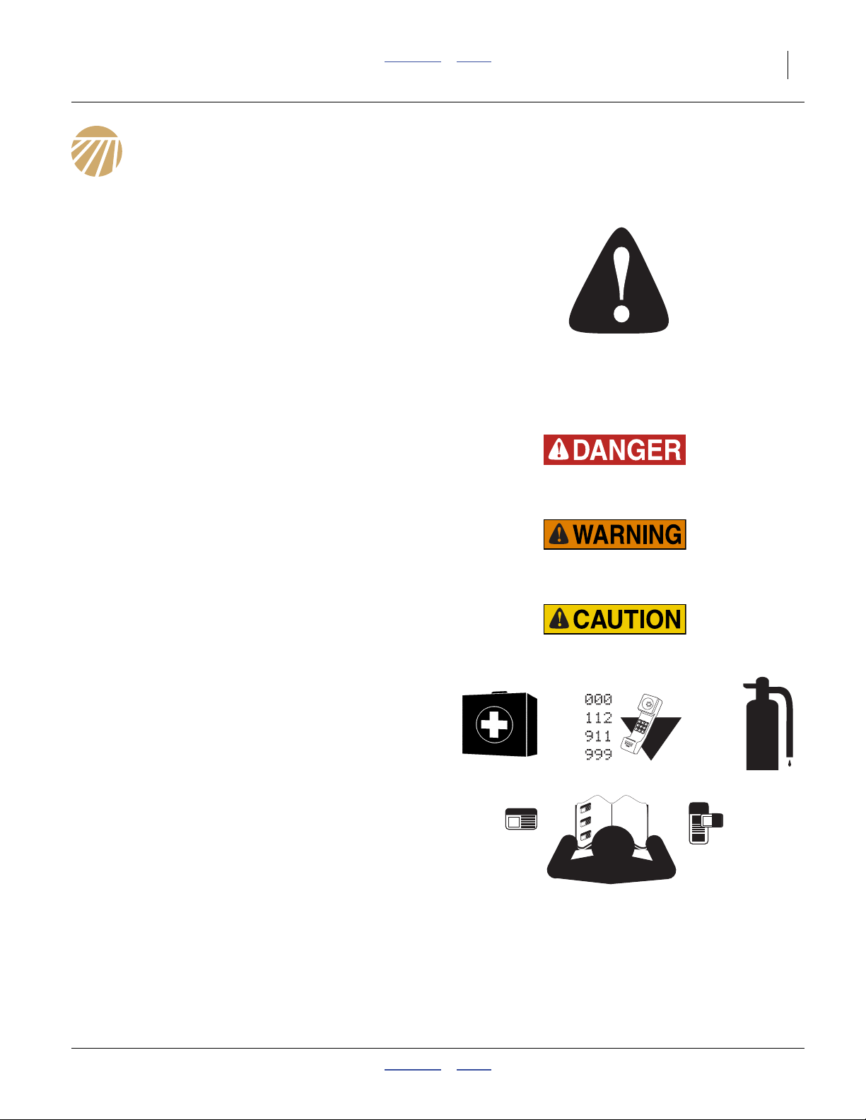
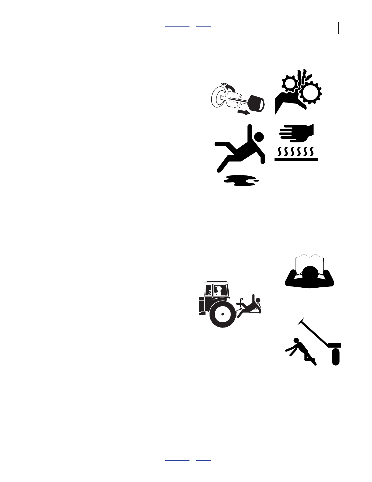
Look for Safety Symbol
The SAFETY ALERT SYMBOL indicates there is a
potential hazard to personal safety involved and extra
safety precaution must be taken. When you see this
symbol, be alert and carefully read the message that follows it. In addition to design and configuration of equipment, hazard control and accident prevention are
dependent upon the awareness, concern, prudence and
proper training of personnel involved in the operation,
transport, maintenance and storage of equipment.
Be Aware of Signal Words
Signal words designate a degree or level of hazard seriousness.
DANGER indicates an imminently hazardous situation
which, if not avoided, will result in death or serious injury.
This signal word is limited to the most extreme situations,
typically for machine components that, for functional purposes, cannot be guarded.
WARNING indicates a potentially hazardous situation
which, if not avoided, could result in death or serious
injury, and includes hazards that are exposed when
guards are removed. It may also be used to alert against
unsafe practices.
CAUTION indicates a potentially hazardous situation
which, if not avoided, may result in minor or moderate
injury. It may also be used to alert against unsafe practices.
Prepare for Emergencies
▲ Be prepared if a fire starts
▲ Keep a first aid kit and fire extinguisher handy.
▲ Keep emergency numbers for doctor, ambulance, hospital
and fire department near phone.
Be Familiar with Safety Decals
▲ Read and understand “Safety Decals” on page 6, thor-
oughly.
▲ Read all instructions noted on the decals.
▲ Keep decals clean. Replace damaged, faded and illegible
decals.
04/04/2011 Contents Index 166-283M
Page 6

2 Great Plains Manufacturing, Inc. Contents Index NTA607/2007HD
Wear Protective Equipment
▲ Wear protective clothing and equipment.
▲ Wear clothing and equipment appropriate for the job. Avoid
loose-fitting clothing.
▲ Because prolonged exposure to loud noise can cause hear-
ing impairment or hearing loss, wear suitable hearing protection such as earmuffs or earplugs.
▲ Because operating equipment safely requires your full
attention, avoid wearing entertainment headphones while
operating machinery.
Use A Safety Chain
▲ Use a safety chain to help control drawn machinery should
it separate from tractor draw-bar.
▲ Use a chain with a strength rating equal to or greater than
the gross weight of towed machinery.
▲ Attach chain to tractor draw-bar support or other specified
anchor location. Allow only enough slack in chain to permit
turning.
▲ Replace chain if any links or end fittings are broken,
stretched or damaged.
▲ Do not use safety chain for towing.
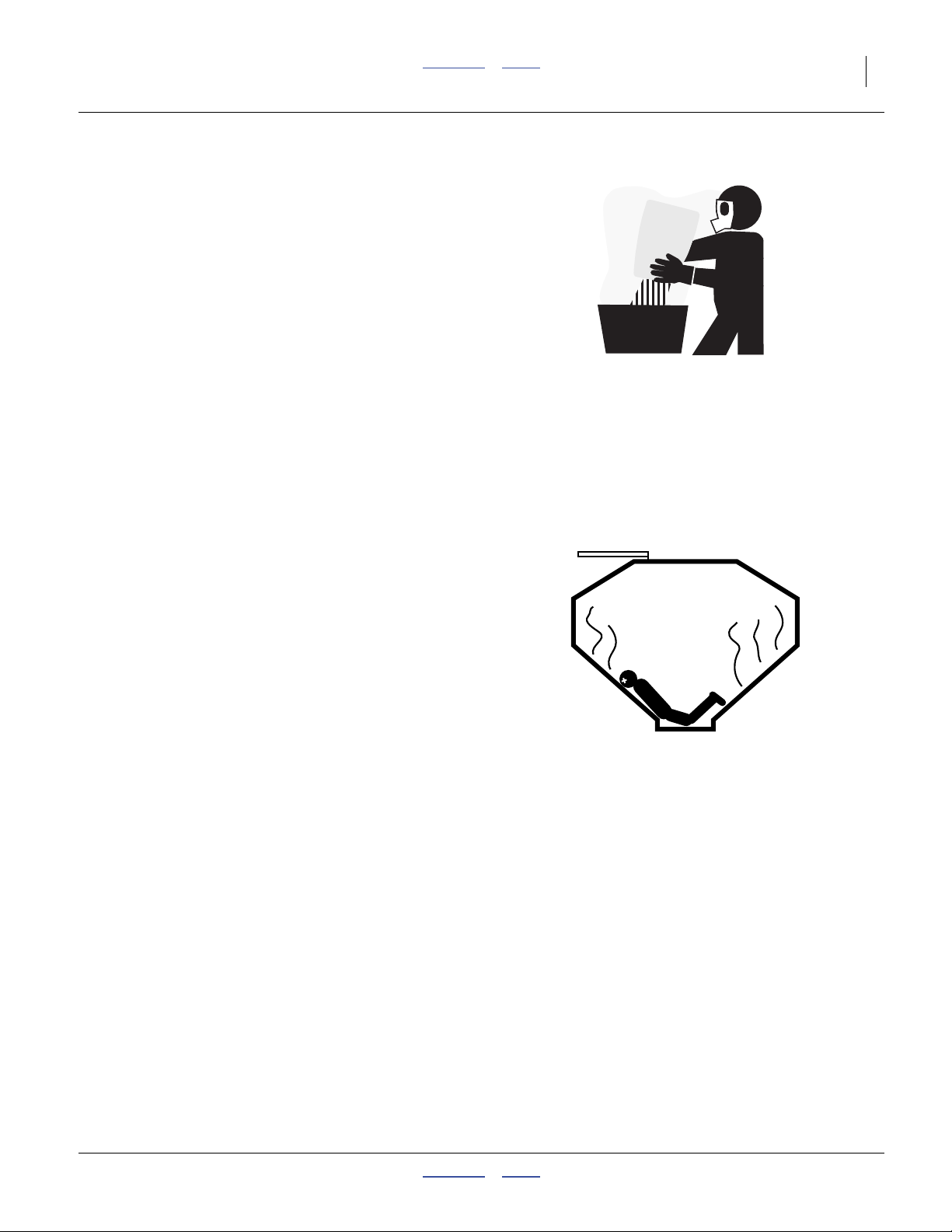
Avoid High Pressure Fluids
Escaping fluid under pressure can penetrate the skin,
causing serious injury.
▲ Avoid the hazard by relieving pressure before disconnecting
hydraulic lines.
▲ Use a piece of paper or cardboard, NOT BODY PARTS, to
check for suspected leaks.
▲ Wear protective gloves and safety glasses or goggles when
working with hydraulic systems.
▲ If an accident occurs, seek immediate medical assistance
from a physician familiar with this type of injury.
Minimize Radiation Exposure
The DICKEY-john® RVS III Radar is an intentional radiator of RF energy. Although its radiated energy level is far
below the limits set by EN 61010-1:1993 A2:1995Chapter 12.4, it is advisable not to look directly into the
face of the unit.
The radar must radiate toward the ground and at least 20
cm (8 inches) away from a human during use to comply
with the RF human exposure limits as called out in
FCC 47 CFR Sec.2.1091. DO NOT RE-MOUNT OR
USE THE RADAR IN A MANNER INCONSISTENT
WITH ITS DEFINED USE.
166-283M Contents Index 04/04/2011
Page 7
Great Plains Manufacturing, Inc. Contents Index Important Safety Information 3
Handle Chemicals Properly
Agricultural chemicals can be dangerous. Improper use
can seriously injure persons, animals, plants, soil and
property.
▲ Do not use liquid seed treatments with the NTA607/2007HD
drill.
▲ Read and follow chemical manufacturer’s instructions.
▲ Wear protective clothing.
▲ Handle all chemicals with care.
▲ Avoid inhaling smoke from any type of chemical fire.
▲ Never drain, rinse or wash dispensers within 30m (100 feet)
of a freshwater source, nor at a car wash.
▲ Store or dispose of unused chemicals as specified by chemi-
cal manufacturer.
▲ Dispose of empty chemical containers properly. Laws gen-
erally require power rinsing or rinsing three times, followed
by perforation of the container to prevent re-use.
Confined Space
With materials loaded, or once used for hazardous fertilizers, or seeds with hazardous treatments, your hoppers
may become
“permit-required confined spaces”
under applicable statutes, regulations, insurance rules or
business policy. The vent tube structure in the hoppers
has features to assist escape, and is not for routine entry.
▲ A hopper that is full or merely appears full can be an
entrapment hazard. You can sink entirely into the material,
or into an oxygen-deficient void, and suffocate in a matter
of seconds. Bridges and crusts are especially dangerous.
▲ When hazardous fumes are present, you can be quickly
overcome even with the hopper lid open.
▲ Do not enter a hopper for material loading, material
unloading, hopper cleaning or meter maintenance.
▲ Clean hopper by power washing from outside hopper top.
▲ Perform meter maintenance by removing meters from bot-
tom of empty hopper.
▲ If obstruction removal or repair requires hopper entry, have
the work performed by a team trained in confined space
procedures. See “Hopper Entry” on page 110.
04/04/2011 Contents Index 166-283M
Page 8
4 Great Plains Manufacturing, Inc. Contents Index NTA607/2007HD
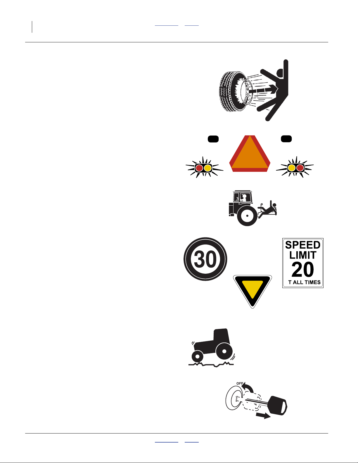
Tire Safety
Tire changing can be dangerous and should be performed by trained personnel using correct tools and
equipment.
▲ When inflating tires, use a clip-on chuck and extension hose
long enough for you to stand to one side–not in front of or
over tire assembly. Use a safety cage if available.
▲ When removing and installing wheels, use wheel-handling
equipment adequate for weight involved.
Use Safety Lights and Devices
Slow-moving tractors and towed implements can create
a hazard when driven on public roads. They are difficult
to see, especially at night.
▲ Use flashing warning lights and turn signals whenever driv-
ing on public roads.
Use lights and devices provided with implement
Keep Riders Off Machinery
Riders obstruct the operator’s view. Riders could be
struck by foreign objects or thrown from the machine.
▲ Never allow children to operate equipment.
▲ Keep all bystanders away from machine during operation.
Transport Machinery Safely
Maximum transport speed for implement is 30 kph or
20 mph. Some rough terrains require a slower speed.
Sudden braking can cause a towed load to swerve and
upset.
▲ Do not exceed 30 kph or 20 mph. Never travel at a speed
which does not allow adequate control of steering and stopping. Reduce speed if towed load is not equipped with
brakes.
▲ Comply with state and local laws.
▲ Do not tow an implement that, when fully loaded, weighs
more than 1.5 times the weight of towing vehicle.
▲ Carry reflectors or flags to mark air drill in case of break-
down on the road.
▲ Keep clear of overhead power lines and other obstructions
when transporting. Refer to transport dimensions under
“Specifications and Capacities” on page 144.
▲ Do not fold or unfold the air drill while the tractor is mov-
ing
Shutdown and Storage
▲ Unfold and lower air drill.
▲ Block tires or use optional drill parking brakes.
▲ Detach and store air drill in an area where children nor-
mally do not play.
A
166-283M Contents Index 04/04/2011
Page 9
Great Plains Manufacturing, Inc. Contents Index Important Safety Information 5
Practice Safe Maintenance
▲ Understand procedure before doing work. Use proper
tools and equipment. Refer to this manual. For brake
work, see specific safety information beginning on
page 118.
▲ Work in a clean, dry area.
▲ Unfold and lower the drill, put tractor in park, turn off
engine, and remove key before performing maintenance. If
work must be performed with implement raised, use center
section lift lock and gauge lock channels provided.
▲ Make sure all moving parts have stopped and all system
pressure is relieved.
▲ Allow drill to cool completely.
▲ Disconnect battery ground cable (-) before servicing or
adjusting electrical systems.
▲ Welding: Disconnect battery ground. Protect hydraulic
lines. Avoid fumes from heated paint.
▲ Inspect all parts. Make sure parts are in good condition
and installed properly.
▲ Remove buildup of grease, oil or debris.
▲ Remove all tools and unused parts from air drill before
operation.
Safety At All Times
Thoroughly read and understand the instructions in this
manual before operation. Read all instructions noted on
the safety decals.
▲ Be familiar with all air drill functions.
▲ Operate machinery from the driver’s seat only.
▲ Do not leave drill unattended with tractor engine running.
▲ Do not stand between the tractor and drill during hitching.
▲ Keep hands, feet and clothing away from power-driven
parts.
▲ Wear snug-fitting clothing to avoid entanglement with mov-
ing parts.
▲ Watch out for wires, trees, etc., when folding and raising air
drill. Make sure all persons are clear of working area.
MetaData: End of <Safety Topics>
Null4:
04/04/2011 Contents Index 166-283M
Page 10
6 Great Plains Manufacturing, Inc. Contents Index NTA607/2007HD
Safety Decals
Safety Reflectors and Decals
Your implement comes equipped with all lights, safety
reflectors and decals in place. They were designed to
help you safely operate your implement.
▲ Read and follow decal directions.
▲ Keep lights in operating condition.
▲ Keep all safety decals clean and legible.
▲ Replace all damaged or missing decals. Order new decals
from your Great Plains dealer. Refer to this section for
proper decal placement.
▲ When ordering new parts or components, also request cor-
responding safety decals.
Reflector: Slow Moving Vehicle (SMV)
NTA607HD: n/a
(International models use
833-398C panels and
833-399C reflectors)
NTA2007HD: 818-055C
To install new decals:
1. Clean the area on which the decal is to be placed.
2. Peel backing from decal. Press firmly on surface,
being careful not to cause air bubbles under decal.
At center of rear caster sub-frame cross-tube;
1 total
See “Transport Safety Information” on page 38.
Null4:
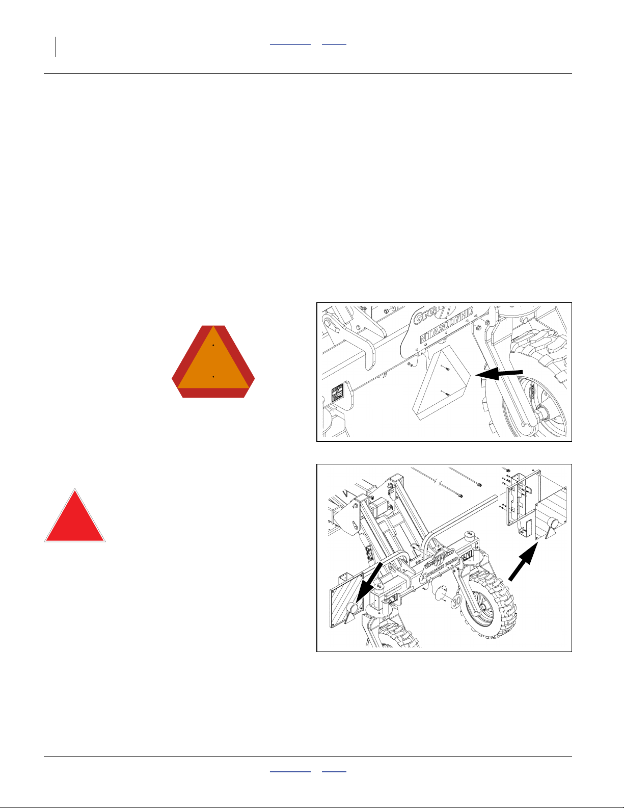
Reflectors: Red Triangles
NTA607HD: 833-399C NTA2007HD: n/a
(North American models
use
818-055C SMV reflectors,
838-266C red reflectors &
838-267C amber reflectors.)
One each rear fluorescent panel;
2 total
See “Transport Safety Information” on page 38.
Null4:
Null4:
31286
Null4:
31287
166-283M Contents Index 04/04/2011
Page 11
Great Plains Manufacturing, Inc. Contents Index Important Safety Information 7
Reflectors: Fluorescent Panels
NTA607HD: 833-398C
NTA2007HD: 833-398C
One each side, cart front
frame, one each side, rear
caster light bar;
One each side, cart front
frame;
2 panels total
4 panels total
See “Transport Safety Information” on page 38.
Null4:
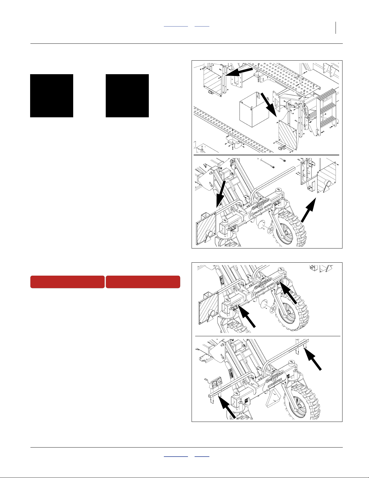
Reflectors: Red
NTA607HD: 838-266C
On rear face of reflector
support tube under lights
(outside of Daytime);
2 total
NTA2007HD: 838-266C
On rear face of lift assist
frame tool bar
(above Daytime);
2 total
Null4:
Null4:
31103
31287
See “Transport Safety Information” on page 38.
Null4:
31286
Null4:
04/04/2011 Contents Index 166-283M
Null4:
31287
Page 12
8 Great Plains Manufacturing, Inc. Contents Index NTA607/2007HD
Reflectors: Daytime
NTA607HD: 838-267C
NTA2007HD: 838-267C
On rear face of reflector
support tube near lights
(inside of Reds);
2 total
On rear face of lift assist
frame tool bar
(below Reds);
2 total
See “Transport Safety Information” on page 38.
Null4:
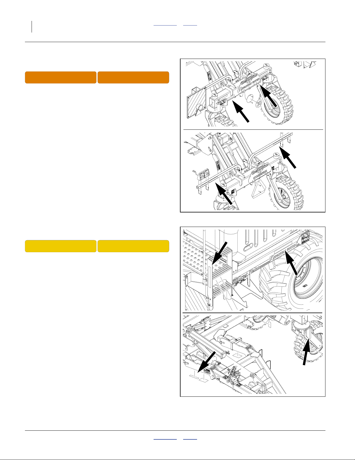
Reflectors: Amber
NTA607HD: 838-265C NTA2007HD: 838-265C
Null4:
31286
Null4:
31287
On sides of cart frame above tires,
on front face of ladders,
on outside face of casters,
on bottom forward face of wing pivot weldment (faces
outward when wings are folded);
8 total.
See “Transport Safety Information” on page 38.
Null4:
Null4:
31236
Null4:
31281
166-283M Contents Index 04/04/2011
Page 13
Great Plains Manufacturing, Inc. Contents Index Important Safety Information 9
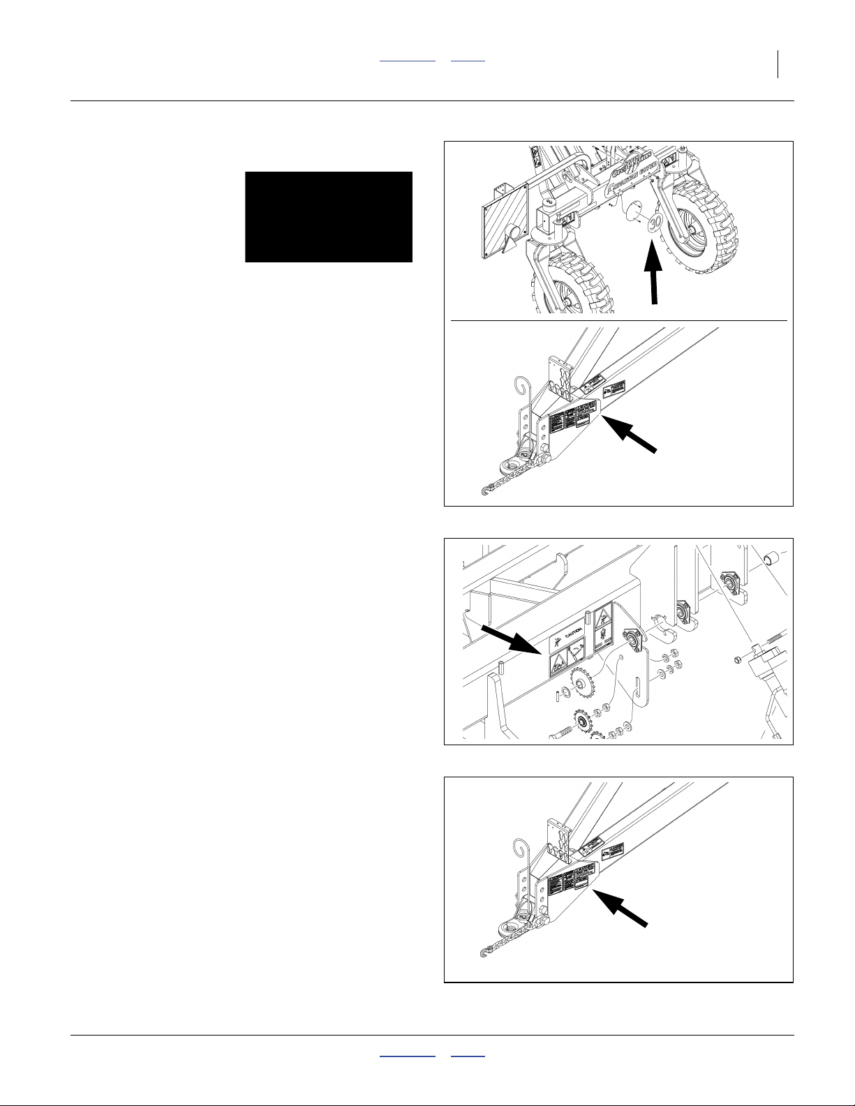
Transport: Speed
NTA607HD: 848-398C
NTA2007HD: 818-188C
Centered on rear caster
sub-frame cross-tube;
On tongue near hitch;
1 total
1 total
See “Transport Safety Information” on page 38.
Null4:
Transport: Brake Roll-Away (Option)
NTA607HD: 848-518C NTA2007HD: 848-518C
On rear cart frame, inside of tires,
present only if brakes are installed;
0 or 2 total
See “Parking” on page 62.
Null4:
31287
Null4:
31175
Null4:
31234
Null4:
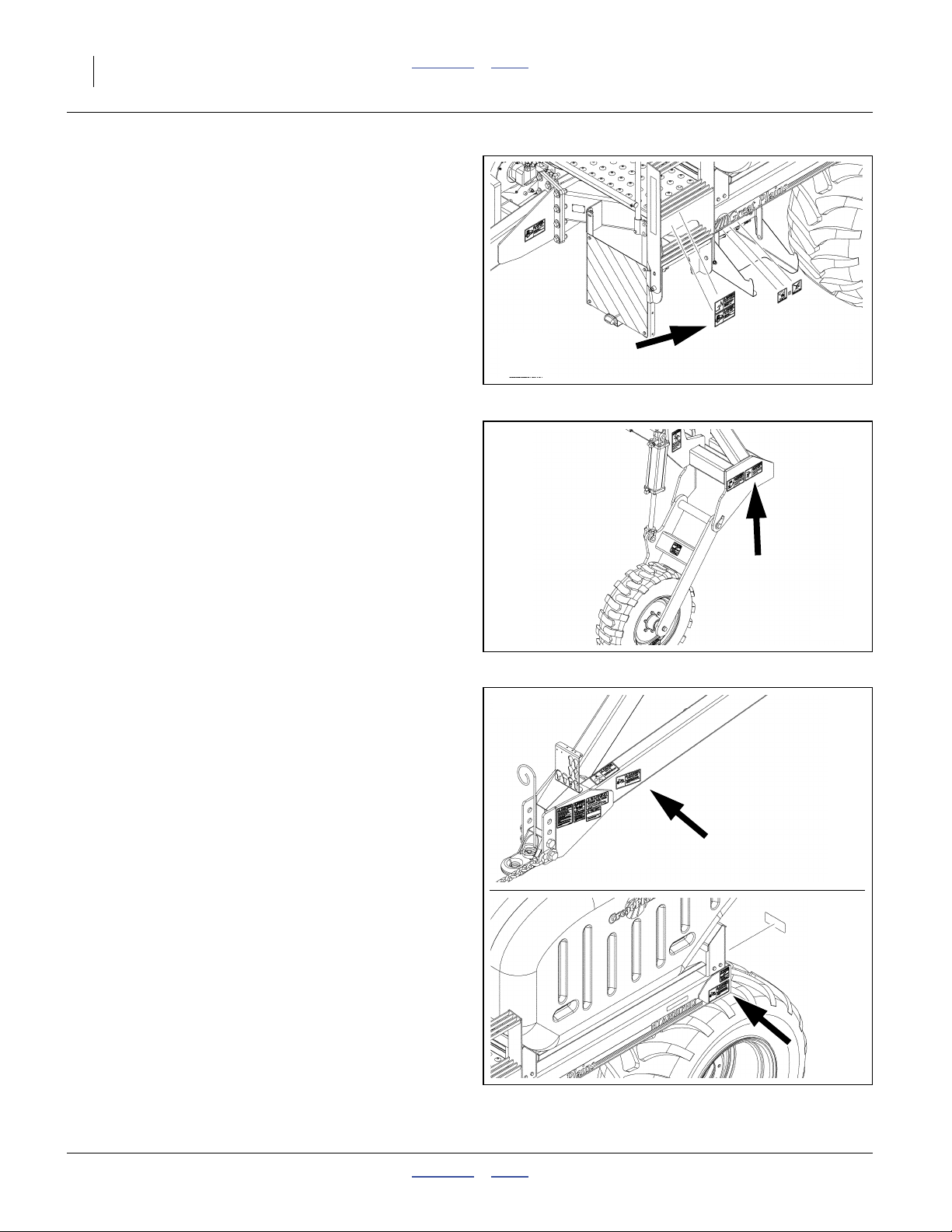
Danger: Read Manual
NTA607HD: n/a
Export models rely on pictorial decals.
See also decal 848-512C on
page 18.
On left side of tongue near hitch;
1 total
Null4:
04/04/2011 Contents Index 166-283M
NTA2007HD: 818-557C
(818-557C Text in Spanish advises
non-English readers to seek translation)
Null4:
31287
Page 14
10 Great Plains Manufacturing, Inc. Contents Index NTA607/2007HD
Danger: Do Not Ride
NTA607HD: 848-511C NTA2007HD: 848-583C
On each side of cart side frame at ladder top;
2 total
Null4:
31287
Null4:
Danger: Crush (Marker Option)
NTA607HD: 848-513C NTA2007HD: 848-581C
On wing tip outside faces,
preset only if markers are installed;
0 or 2 total
See “Marker Operation (Option)” on page 58.
Null4:
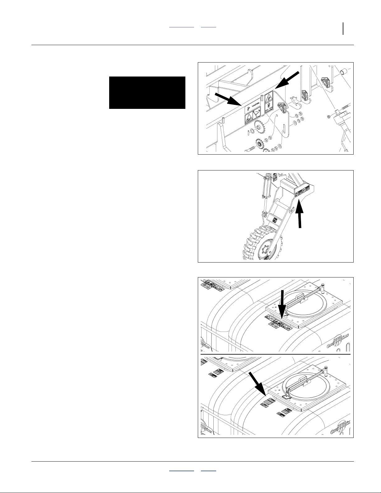
Danger: Electrocution
NTA607HD: 848-516C NTA2007HD: 848-574C
On left side of tongue near hitch,
on sides of cart frame above tires;
3 total
See “Transporting the Air Drill” on page 38.
Null4:
31234
Null4:
31281
Null4:
31234
Null4:
166-283M Contents Index 04/04/2011
Page 15
Great Plains Manufacturing, Inc. Contents Index Important Safety Information 11
Danger: Hitch Crushing
NTA607HD: 848-523C NTA2007HD: 818-624C
On outside rear faces of cart frame, above tires;
2 total
See “Unfolding and Folding” on page 30.
Null4:
31175
See “Lowering and Raising Air Drill” on page 35.
Null4:
Danger: Marker Crush (Option)
NTA607HD: 848-528C NTA2007HD: 848-580C
On wing outside faces
preset only if markers are installed;
0 or 2 total
See “Marker Safety Information” on page 59.
Null4:
Danger: Chemicals
NTA607HD: 848-520C NTA2007HD: 818-323C
On each hopper, near lid,
1 or 2 total
See “Loading Material Safely” on page 47.
See “Loading Liquid Fertilizer (Option)” on page 50.
Null4:
31281
Null4:
31236
Null4:
31234
Null4:
04/04/2011 Contents Index 166-283M
Page 16
12 Great Plains Manufacturing, Inc. Contents Index NTA607/2007HD
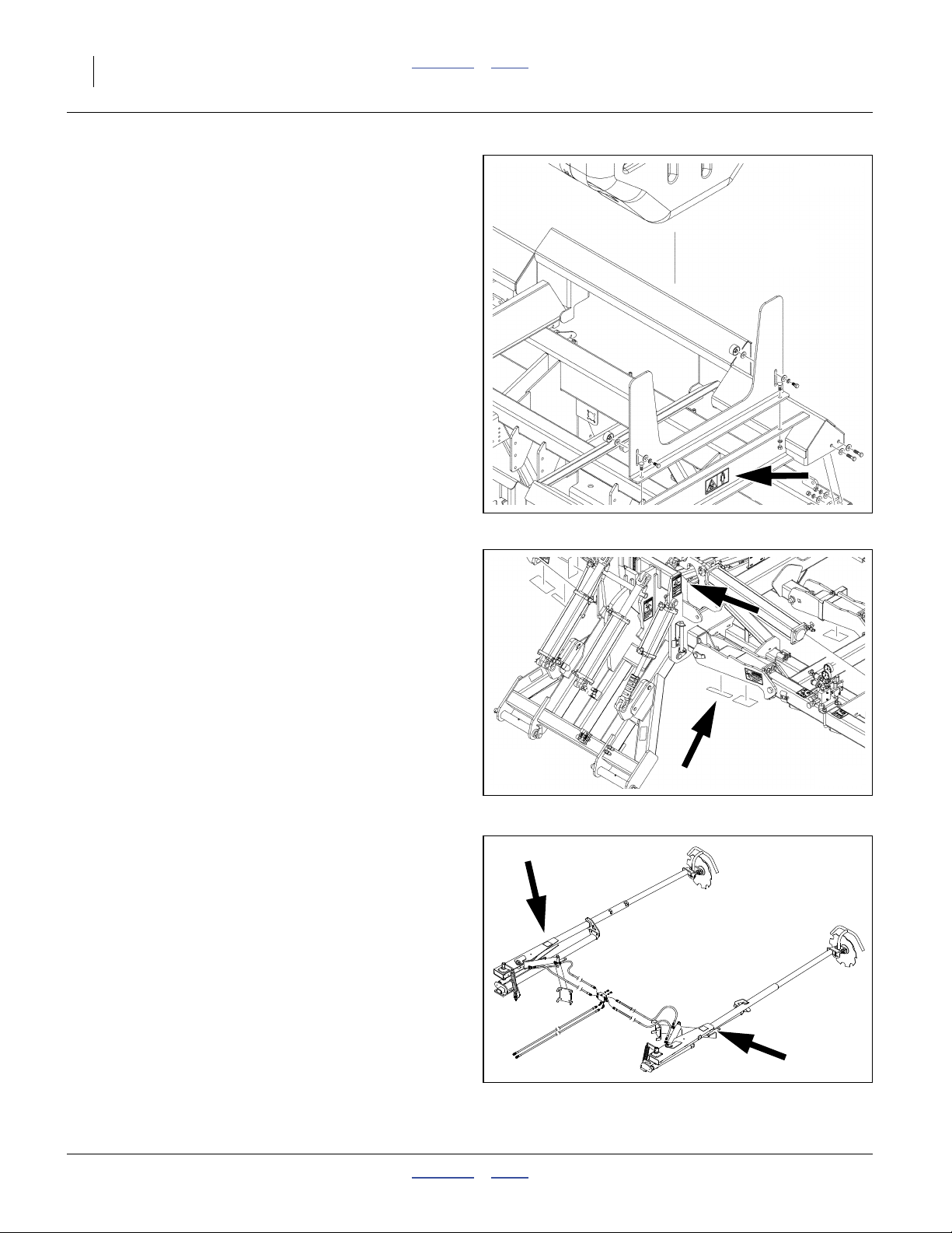
Danger: Chemicals (Option)
NTA607HD: 848-529C NTA2007HD: 818-323C
on tank cradles,
preset only if liquid fertilizer system installed;
0 or 2 total
See “Loading Liquid Fertilizer (Option)” on page 50.
Null4:
Danger: Wing Crushing
NTA607HD: 848-530C NTA2007HD: 848-579C
Null4:
31124
On outside faces of center frame weldment riser,
on bottom face of front wing pivot arm
(faces outward when wings are folded);
4 total
See “Unfolding and Folding” on page 30.
Null4:
Danger: Marker Pinch (Option)
NTA607HD: COV-2753 NTA2007HD: COV-2753
On upper face at rear of primary marker arm (when
wings are unfolded).
Note: This is a Haukaas-supplied decal and does not
need to be replaced if lost, damaged or illegible.
The hazards it refers toare covered by Great Plains
decal part numbers 848-513C, 848-528C,
848-580C and 848-581C.
Null4:
Null4:
31281
Null4:
31327
166-283M Contents Index 04/04/2011
Page 17
Great Plains Manufacturing, Inc. Contents Index Important Safety Information 13
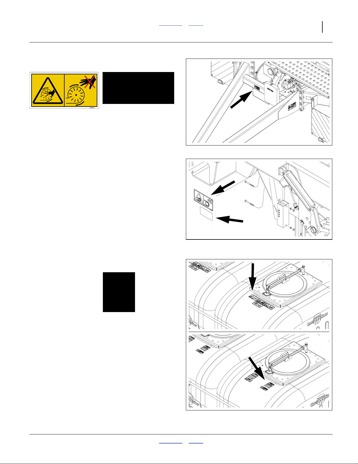
Warning: Fan Hazard
NTA607HD: 838-508C NTA2007HD: 818-632C
On front face of tongue cross-tube near fan;
one total
See “Fan Safety Information” on page 56.
Null4:
Warning: Moving Chain
NTA607HD: 838-509C NTA2007HD: 818-860C
On right cart frame near contact drive,
on bearing plate near calibration crank shaft,
on bottom of hoppers above meter input sprocket;
4 or 5 total
See “Calibration Crank, Bag and Scale” on page 52.
Null4:
Null4:
31234
Null4:
31195
Warning: Wear Eye Protection
NTA607HD: 848-510C NTA2007HD: 848-392C
On each hopper at lid, walkboard side;
1 or 2 total
See “Loading Material Safely” on page 47.
Null4:
Null4:
31236
Null4:
31234
04/04/2011 Contents Index 166-283M
Page 18
14 Great Plains Manufacturing, Inc. Contents Index NTA607/2007HD
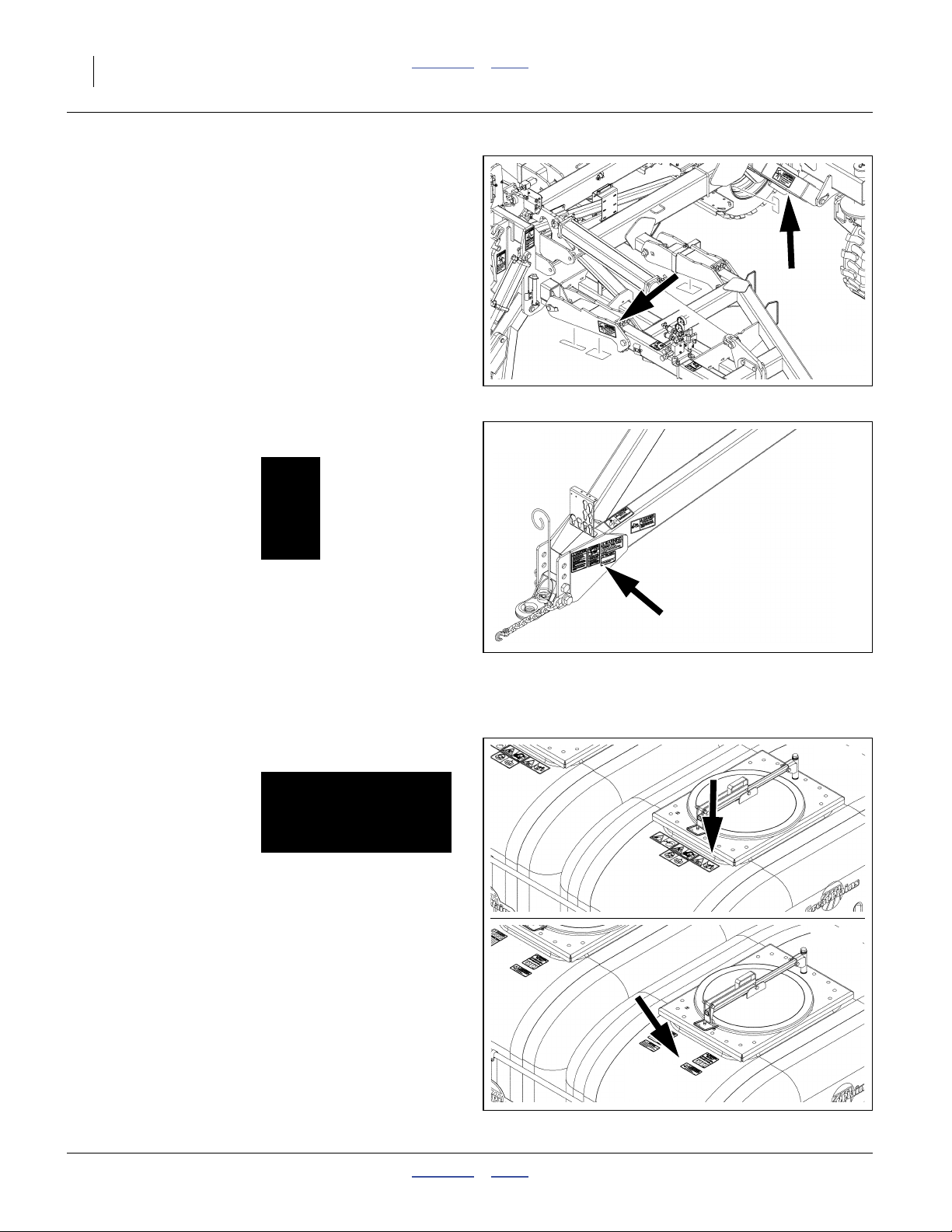
Warning: Pinch Point
NTA607HD: 848-514C NTA2007HD: 848-582C
On front face of wing pivot links,
on outside faces of rear parallel arms;
4 total
See “Unfolding and Folding” on page 30.
Null4:
Null4:
31281
Warning: High Pressure Fluid
NTA607HD: 848-517C NTA2007HD: 818-437C
On left side of tongue near hitch,
at hydraulic port bulkhead on rear of cart;
2 total
See “Hydraulic Hose Hookup” on page 23.
See “Hydraulic Maintenance Safety Information” on
page 114
See “Fan Safety Information” on page 56.
See “Weight Transfer Safety Information” on page 85.
Null4:
Warning: Confined Space
NTA607HD: 848-519C NTA2007HD: 818-628C
On each hopper at lid, walkboard side;
1 or 2 total
See “Hopper Lid Safety Information” on page 43.
See “Loading Material Safely” on page 47.
See “Material Clean-Outs” on page 109.
Null4:
31234
Null4:
31236
Null4:
31234
Null4:
166-283M Contents Index 04/04/2011
Page 19
Great Plains Manufacturing, Inc. Contents Index Important Safety Information 15
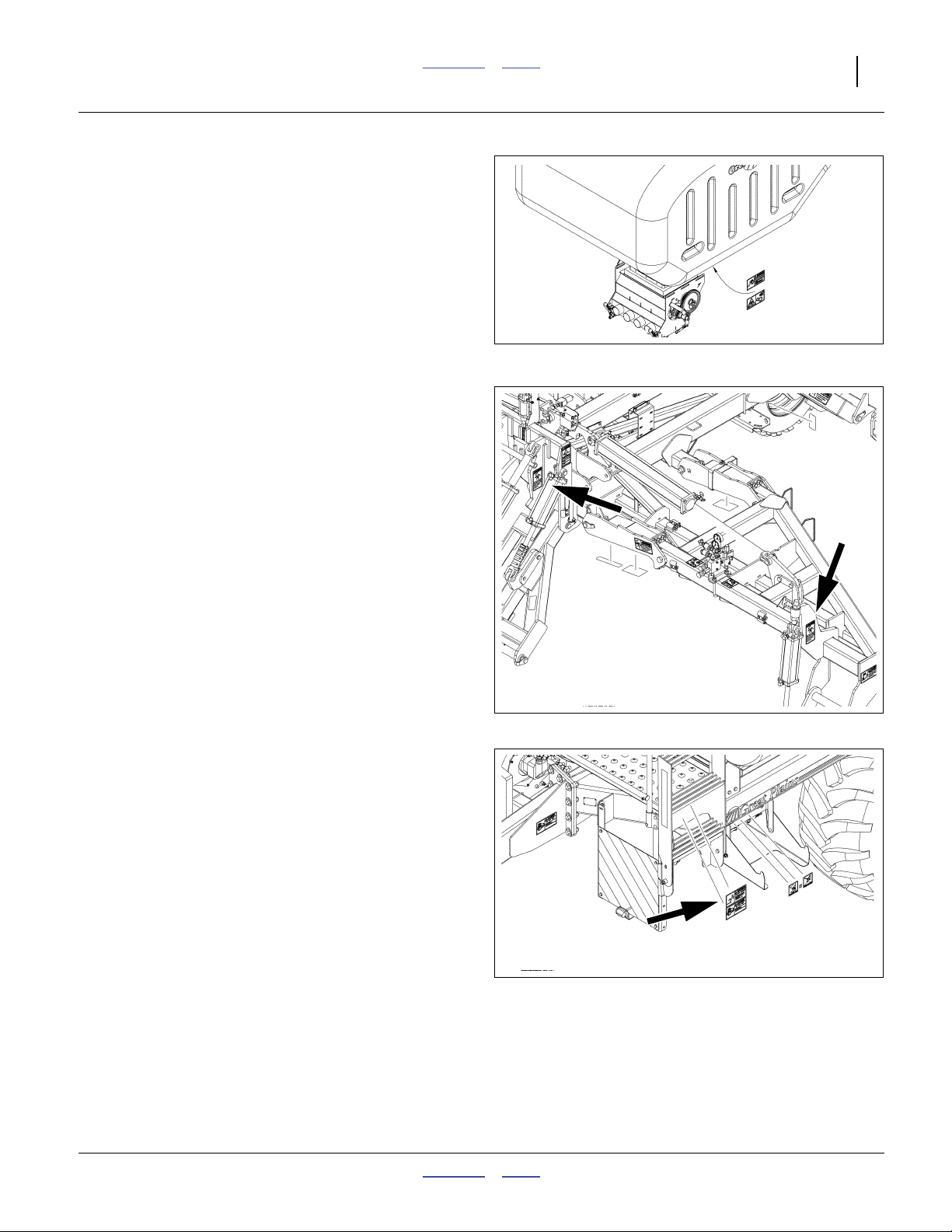
Warning: Moving Gears
NTA607HD: 848-522C NTA2007HD: 848-576C
On bottom of hoppers above final Range gears;
1 or 2 total
Null4:
31371
See “Seed Meter Final Drive Range” on page 71.
Null4:
Warning: Pinch Point
NTA607HD: 848-525C NTA2007HD: 848-578C
On outside faces of flex link weldment,
on outside face of cylinder lug above wing gauge wheels;
4 total
See “Weight Transfer Safety Information” on page 85.
Null4:
Warning: Falling Hazard
NTA607HD: 848-527C NTA2007HD: 848-575C
On each side of cart side frame at ladder top;
2 total
See “Ladder Operations” on page 42.
Null4:
Null4:
31281
Null4:
31287
04/04/2011 Contents Index 166-283M
Page 20
16 Great Plains Manufacturing, Inc. Contents Index NTA607/2007HD
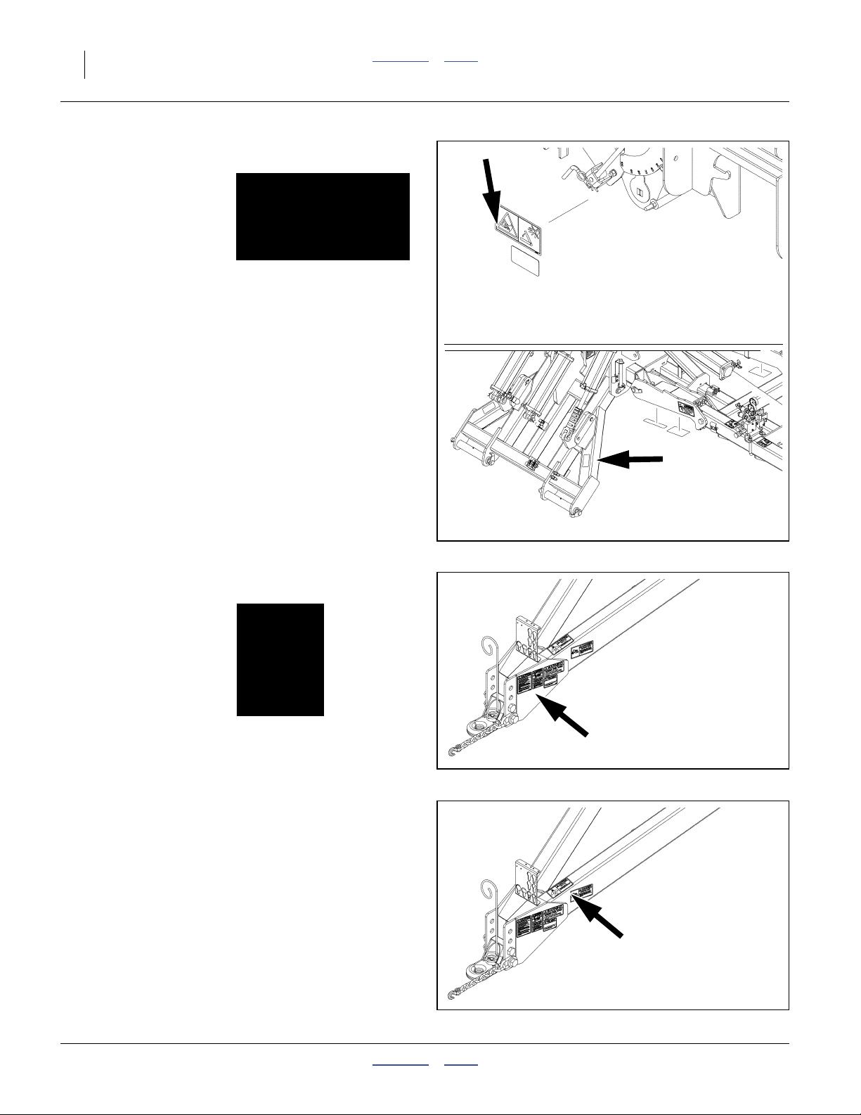
Warning: Hand Pinch
NTA607HD: 848-531C NTA2007HD: 818-798C
On gearbox mounting plate near adjuster crank,
on top outside face of cart-implement link arms;
3 or 4 total
See “Setting Material Rates” on page 65.
Null4:
31195
Null4:
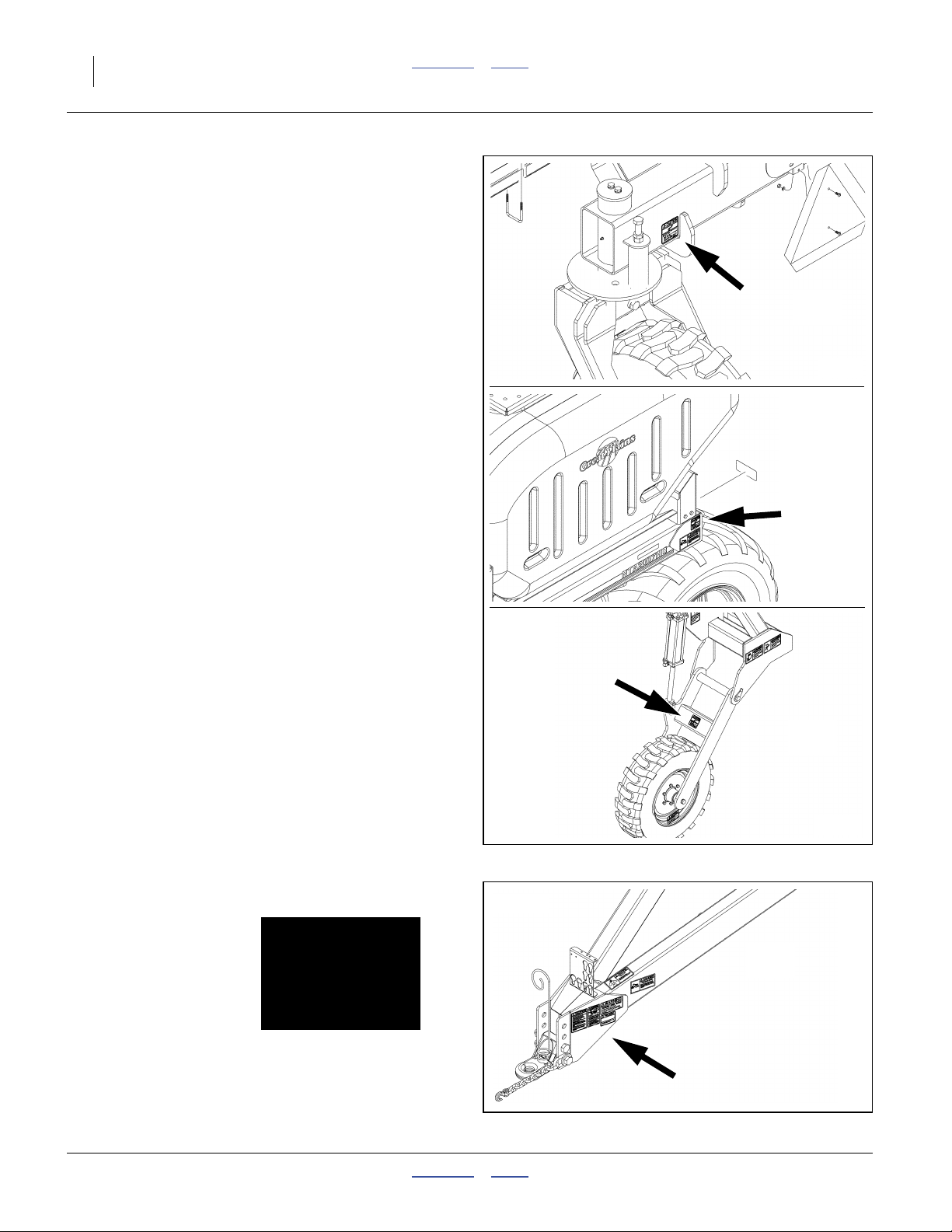
Caution: Read Operator Manual
NTA607HD: 848-512C NTA2007HD: 818-630C
On left side of tongue near hitch;
1 total
Null4:
Caution: Radar in Use
NTA607HD: 838-506C NTA2007HD: 848-577C
Null4:
31234
Null4:
31234
Null4:
31281
On top side of tongue near radar transceiver,
1 total
See “Minimize Radiation Exposure” on page 2.
Null4:
166-283M Contents Index 04/04/2011
Page 21
Great Plains Manufacturing, Inc. Contents Index Important Safety Information 17
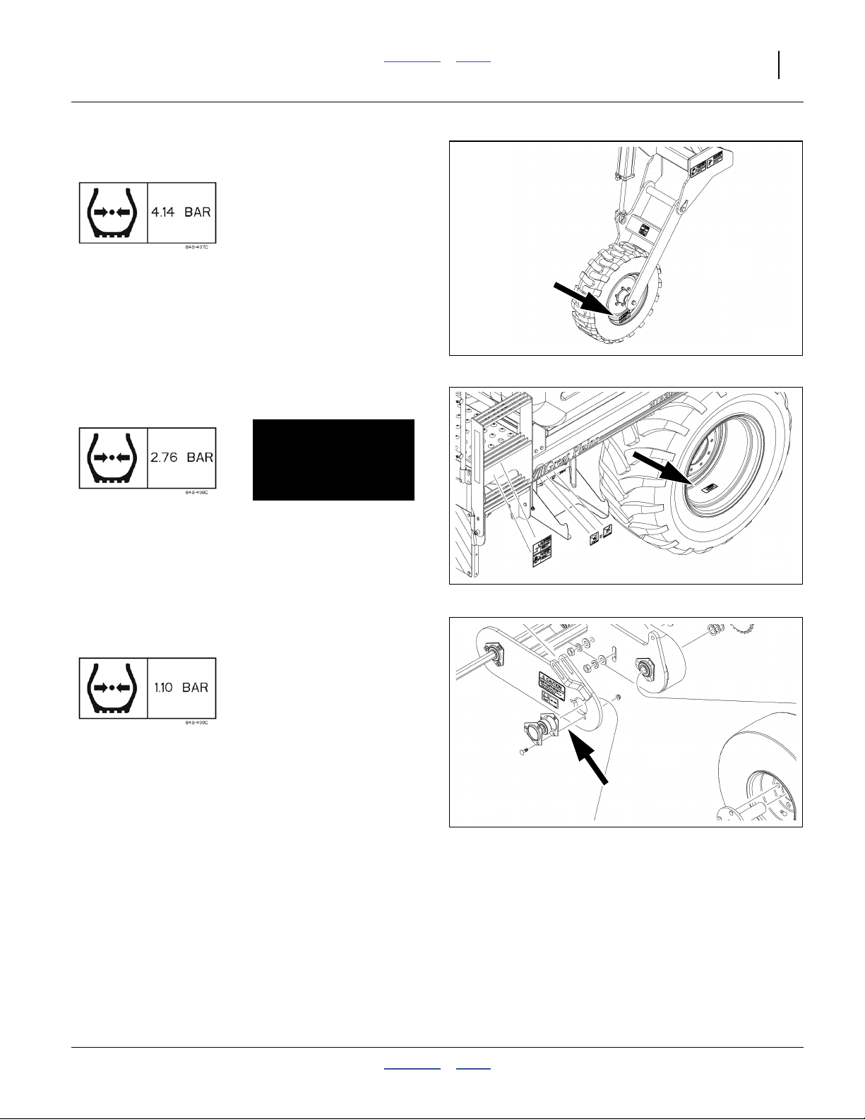
Caution: Tire Pressure and Torque
NTA607HD: 848-497C NTA2007HD: 838-092C
On rims of implement gauge and lift wheels;
4 total
See “Transport Safety Information” on page 38.
See “Leveling Implement” on page 129.
Null4:
Null4:
31281
Caution: Tire Pressure and Torque
NTA607HD: 848-498C NTA2007HD: 848-102C
On outside rim each cart transport wheel;
2 total
See “Contact Drive Re-setting” on page 113.
Null4:
Caution: Tire Pressure and Torque
NTA607HD: 848-499C NTA2007HD: 848-484C
On inside face of contact drive wheel arm;
1 total
See “Transport Safety Information” on page 38.
Null4:
Null4:
31175
Null4:
31287
04/04/2011 Contents Index 166-283M
Page 22
18 Great Plains Manufacturing, Inc. Contents Index NTA607/2007HD
Caution: Tires Not A Step
NTA607HD: 838-507C NTA2007HD: 818-398C
On rear face of lift assist frame tool bar above casters,
rear face of cart frame near transport tires,
on gauge wheel arms above tires;
6 total
See “Unfold/Fold: Safety Information” on page 30.
See “Unfold/Fold: Safety Information” on page 30.
See “Weight Transfer Safety Information” on page 85.
Null4:
31286
Null4:
Caution: Use Adequate Tractor
NTA607HD: n/a NTA2007HD: 848-623C
Null4:
31234
Null4:
31234
Null4:
31281
On left side of tongue near
hitch;
MetaData: End of “Safety Decals”.
MetaData: End of “Important Safety Information”.
166-283M Contents Index 04/04/2011
1 total
Page 23
Great Plains Manufacturing, Inc. Contents Index 19
Introduction
Great Plains welcomes you to its growing family of new
product owners. Your 6m/20ft No-Till Heavy Duty Air Drill
has been designed with care and built by skilled workers
using quality materials. Proper setup, maintenance, and
safe operating practices will help you get years of satisfactory use from the machine.
Models Covered
NTA607HD-3275 6m, 32-row, 19.1cm (7.5in) spacing
NTA607HD-4006 6m, 40-row, 15.0cm (5.9in) spacing
NTA2007HD-3275 20ft, 32-row, 7.5in spacing
NTA2007HD-4006 20ft, 40-row, 6in spacing
See “Specifications and Capacities” on page 144 for
precise swath information.
Description of Unit
The NTA607/2007HD Drill is a pull-type integrated air
drill. It has single or dual hoppers for separate or simultaneous delivery of seed and/or granulated dry fertilizer.
Hydraulic weight transfer is standard.
A single-hopper configuration may have liquid fertilizer
saddle tanks. Each hopper has an independent metering
system with infinite ratio gearboxes. The NTA607/
2007HD Drill folds for narrow (3m) transport.
The NTA607HD or NTA2007HD has double-disk Series
07HD heavy duty openers, suitable for conventional till
and, minimum-till conditions. With optional coulters, the
drill is suitable for moderate no-till conditions.
The NTA607/2007HD offers optional brakes. Service
brakes are operated by air or hydraulic lines to the tractor. Parking brakes are manually operated at the drill.
Other options include variable rate meter servo and
markers.
Document Family
166-283M Owner’s Manual (this document)
167-085B Seed Rate Charts
166-283P Parts Manual
166-263M Variable Rate Kit Installation
113-850M Marker Installation
12-M-43 CDS-JohnBlue NGP-6055K pump
110011544 DICKEY-john® Quick Start Guide
110011375 DICKEY-john® Air Cart Control manual
110111543 DICKEY-john® Tramline Kit instructions
U
R
F
B
L
D
R
L
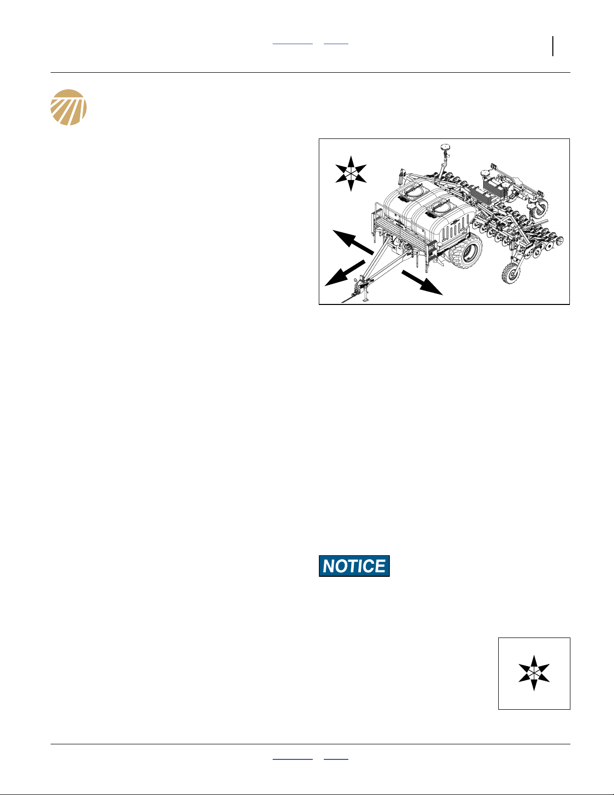
Null4:
Figure 1
NTA607/2007HD Air Drill
Intended Usage
Use the NTA607/2007HD Drill to seed and fertilize production-agriculture crops only. Do not modify the air drill
for use with attachments other than Great Plains options
and accessories specified for use with the NTA607/
2007HD Drill.
Using This Manual
This manual will familiarize you with safety, hitching,
operation, adjustments, troubleshooting, and maintenance. Read this manual and follow the recommendations to help ensure safe and efficient operation.
The information in this manual is current at printing.
Some parts may change to assure top performance.
Definitions
The following terms are used throughout this manual.
A crucial point of information related to the preceding topic.
Read and follow the directions to remain safe, avoid serious
damage to equipment and ensure desired field results.
Note: Useful information related to the preceding topic.
Right-hand and left-hand as used in
this manual are determined by facing
the direction the machine will travel
while in use unless otherwise stated.
An orientation rose in some line art
illustrations shows the directions of:
Up, Back, Left, Down, Front, Right.
R
F
31285
U
B
L
D
04/04/2011 Contents Index 166-283M
Page 24

20 Great Plains Manufacturing, Inc. Contents Index NTA607/2007HD
Owner Assistance
If you need customer service or repair parts, contact a
Great Plains dealer. They have trained personnel, repair
parts and equipment specially designed for Great Plains
products.
Refer to Figure 2
Your machine’s parts were specially designed and
should only be replaced with Great Plains parts. Always
use the serial and model number when ordering parts
from your Great Plains dealer. The serial-number plate is
located on the left side main frame, below crank.
Record your NTA607/2007HD Drill model and serial
number here for quick reference:
Model Number:__________________________
Serial Number: __________________________
Your Great Plains dealer wants you to be satisfied with
your new machine. If you do not understand any part of
this manual or are not satisfied with the service received,
please take the following actions.
Null4:
1. Discuss the matter with your dealership service
manager. Make sure they are aware of any problems
so they can assist you.
2. If you are still unsatisfied, seek out the owner or gen-
eral manager of the dealership.
Null4:
Figure 2
Serial Number Plate
For further assistance write to:
Product Support
Great Plains Mfg. Inc., Service Department
PO Box 5060
Salina, KS 67402-5060
31174
785-823-3276
MetaData: End of “Introduction”
166-283M Contents Index 04/04/2011
Page 25

Great Plains Manufacturing, Inc. Contents Index 21
Preparation and Setup
This section helps you prepare your tractor and NTA607/
2007HD Drill for use, and covers seasonal tasks, and
task when the tractor/air drill configuration changes.
Before using the NTA607/2007HD Drill in the field, you
must hitch the air drill to a suitable tractor, inspect systems and level the air drill. Before using the air drill for
the first time, and periodically thereafter, certain adjustments and calibrations are required.
Initial Setup
See “Appendix B - Initial Setup” on page 162 and
“Appendix C - Option Installation” on page 163 for predelivery items (normally completed by dealer), and firsttime/infrequent setup tasks, including:
• Install seed monitor console in tractor (page 162).
• Set marker extension (page 95) and speed.
Seasonal Setup
On initial delivery, use with a new tractor, and seasonally,
check and as necessary, complete these items before
continuing to the routine setup items:
• Bleed hydraulic system (page 114).
• Wing leveling and alignment (page 129).
• Speed sensor calibration (DICKEY-john® Air Cart
Control manual).
• Blow out entire air system to remove condensation.
Check air flow at each row, for evidence of plugging.
• De-grease exposed cylinder rods if so protected at last
storage.
Pre-Planting Setup
Complete this checklist before routine setup:
❑ Read and understand “Important Safety Informa-
tion” on page 1.
❑ Check that all working parts are moving freely, bolts
are tight, and cotter pins are spread.
❑ Check that all grease fittings are in place and lubri-
cated. See “Lubrication and Scheduled Mainte-
nance” on page 132.
❑ Check that all safety decals and reflectors are cor-
rectly located and legible. Replace if damaged. See
“Safety Decals” on page 6.
❑ Inflate tires to pressure recommended and tighten
wheel bolts as specified. See “Tire Inflation Chart”
on page 147.
04/04/2011 Contents Index 166-283M
Page 26
22 Great Plains Manufacturing, Inc. Contents Index NTA607/2007HD
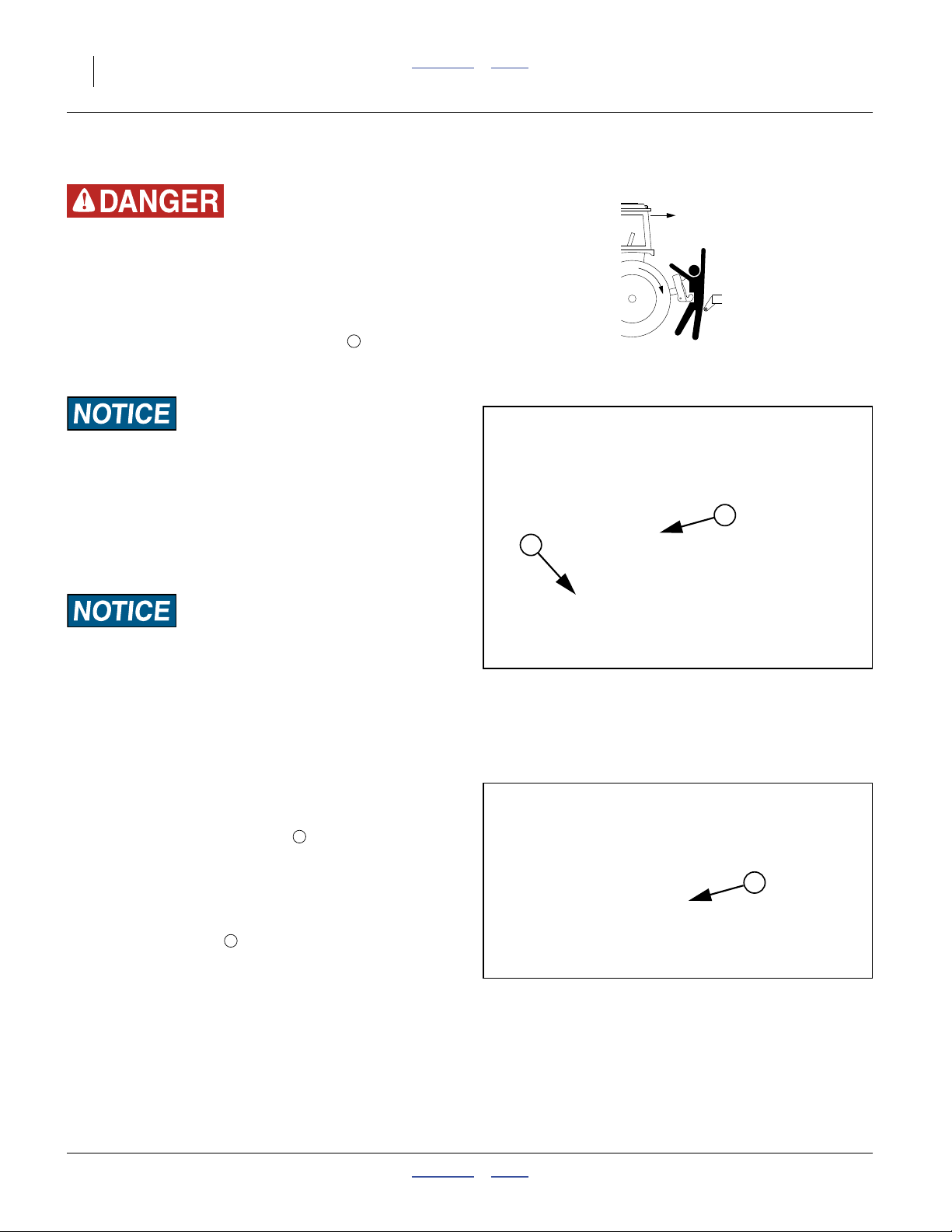
Hitching Tractor to Air Drill
Crushing Hazard:
You may be severely injured or killed by being crushed
between the tractor and air drill. Do not stand or place any
part of your body between air drill and moving tractor. Stop
tractor engine and set tractor parking brake before attaching
cables and hoses.
1. With the drill still on the parking jack , check that
the drill cart frame is level. See “Heights and Level-
ing” on page 26 for details on setting level.
Implement Lift and Speed Error Risks:
The frame must be level both for proper operation of the implement, and to avoid frequent re-calibration of the speed radar.
Refer to Figure 3
2. Move the tractor to near hitching position. Put the
tractor in Park and shut down the tractor. If the tractor draw bar height is incompatible with the drill hitch
height, move and/or invert the hitch to match.
1
1
2
Hitch Failure Risk:
The hitch may be mounted inverted if necessary, but always
have two (2) bolts in two holes of both tongue and hitch. See
“Heights and Leveling” on page 26 for hitch adjustments.
3. Remove hitch pin.
Back tractor to align draw bar and drill hitch.
Shut down tractor and remove key.
4. Use parking jack to lower drill tongue onto tractor
draw bar. Secure hitch to bar with pin. Secure pin
with any means provided.
5. Securely attach safety chain to a tractor anchor of
2
sufficient strength to control the drill in the event of a
hitch failure.
6. Use crank to raise jack foot. Remove pin and jack.
Refer to Figure 4
7. Store jack on stob inside right tongue tube.
3
8. Connect hydraulic hoses (page 23).
9. Connect brake hoses (option, page 24).
10. Connect electrical cables (page 26).
Null4:
Null4:
Figure 3
Hitch on Parking Jack
Figure 4
Parking Jack Stored
31127
3
31128
166-283M Contents Index 04/04/2011
Page 27
Great Plains Manufacturing, Inc. Contents Index Preparation and Setup 23
Hydraulic Hose Hookup
High Pressure Fluid Hazard:
Escaping fluid under pressure can have sufficient pressure to
penetrate the skin causing serious injury. Avoid the hazard by
relieving pressure before disconnecting hydraulic lines. Use a
piece of paper or cardboard, NOT BODY PARTS, to check for
leaks. Wear protective gloves and safety glasses or goggles
when working with hydraulic systems. If an accident occurs,
seek immediate medical assistance from a physician familiar
with this type of injury.
Only trained personnel should work on system hydraulics!
Great Plains hydraulic hoses are color coded to help you
hookup hoses to your tractor outlets. Hoses that go to
the same remote valve are marked with the same color.
The fan pressure hose (yellow) must be connected to a
circuit capable of continuous flow at high volume.
Note: This implement is compatible only with tractors
having Closed Center hydraulics.
Refer to Figure 5
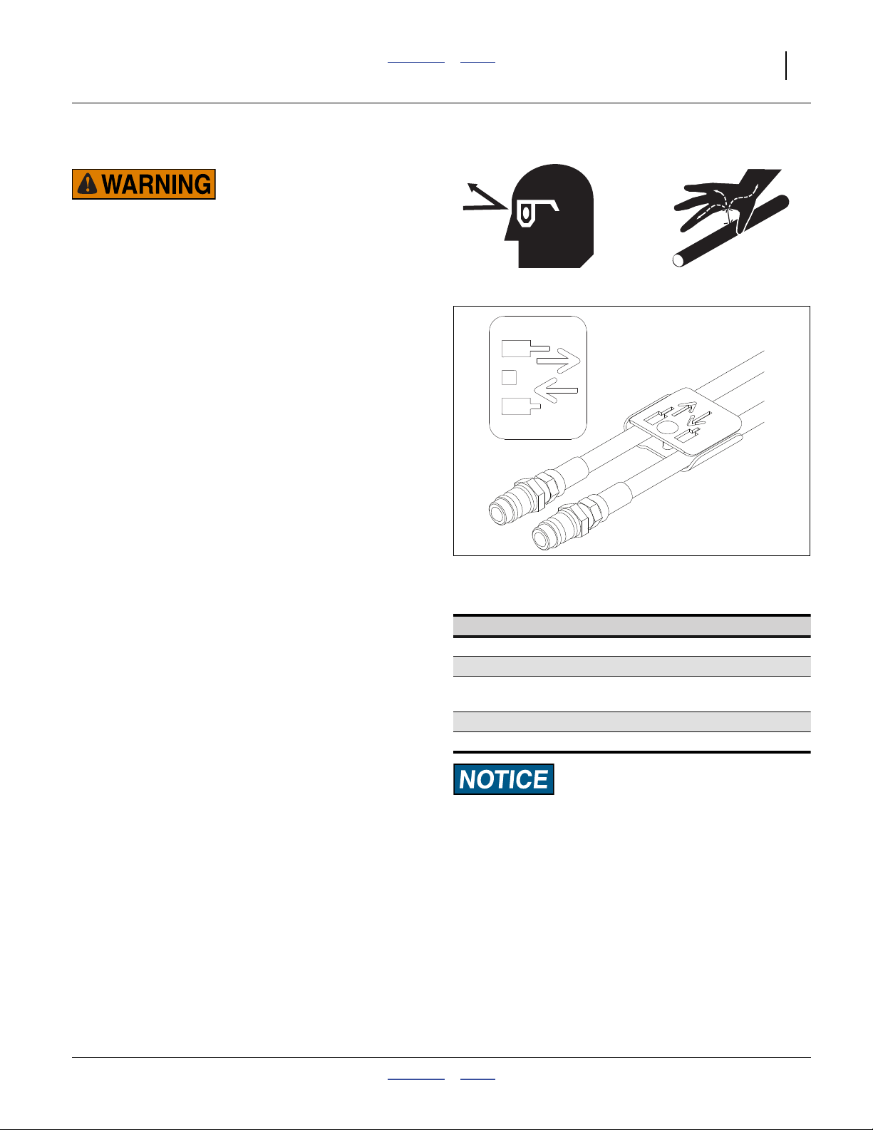
To distinguish hoses on the same hydraulic circuit, refer
to plastic hose label. The hose under an extended-cylinder symbol feeds a cylinder base end. The hose under a
retracted-cylinder symbol feeds a cylinder rod end.
For the hydraulic fan, connect the hose under the
retracted cylinder symbol to the pressure side of the
motor.
The fan motor further requires hookup of a (third) case
drain line, which returns lubricating/cooling fluid.
Marker hoses are provided on the cart even if markers
are not installed on the implement. See “Marker Hose
Tips” on page 162 prior to first hitching.
Null4:
Figure 5
Null4:
Null4:
Hose Label
Color Hydraulic Function
Orange Marker / Auxiliary
Blue Opener Lift
Yellow Wing Fold / Weight Transfer / Lock
Fan (via shutoff valve)
Black Sump
“BRAKES” Hydraulic trailer brakes (Option)
27270
Protecting Fan Hydraulic Motor Seals
Low Pressure (Case) Drain Connection:
11. Attach case drain hose to low pressure drain connection. See Notice at right.
12. Connect low pressure motor return hose, marked
“SUMP”, to a high volume low pressure return port.
The sump line is distinguished by a large (1.06in/
2.7cm diameter) quick coupler.
13. Connect hydraulic hoses to tractor remotes.
Null4:
04/04/2011 Contents Index 166-283M
Equipment Damage Risk:
Case Drain Hose must be attached first, prior to inlet and
return hoses being connected, to prevent damage to hydraulic
motor seals. The case drain has the smaller1⁄4in I.D. hose and
small, flat-face, low-seep connector. DO NOT connect the case
drain line to a power-beyond port.
Case Drain Hose must be detached last, to prevent damage to
the fan motor. To allow pressure relief during temperature
cycles, it is normal for this line to release small amounts of oil
even when stored with the connector elevated.
Page 28
24 Great Plains Manufacturing, Inc. Contents Index NTA607/2007HD
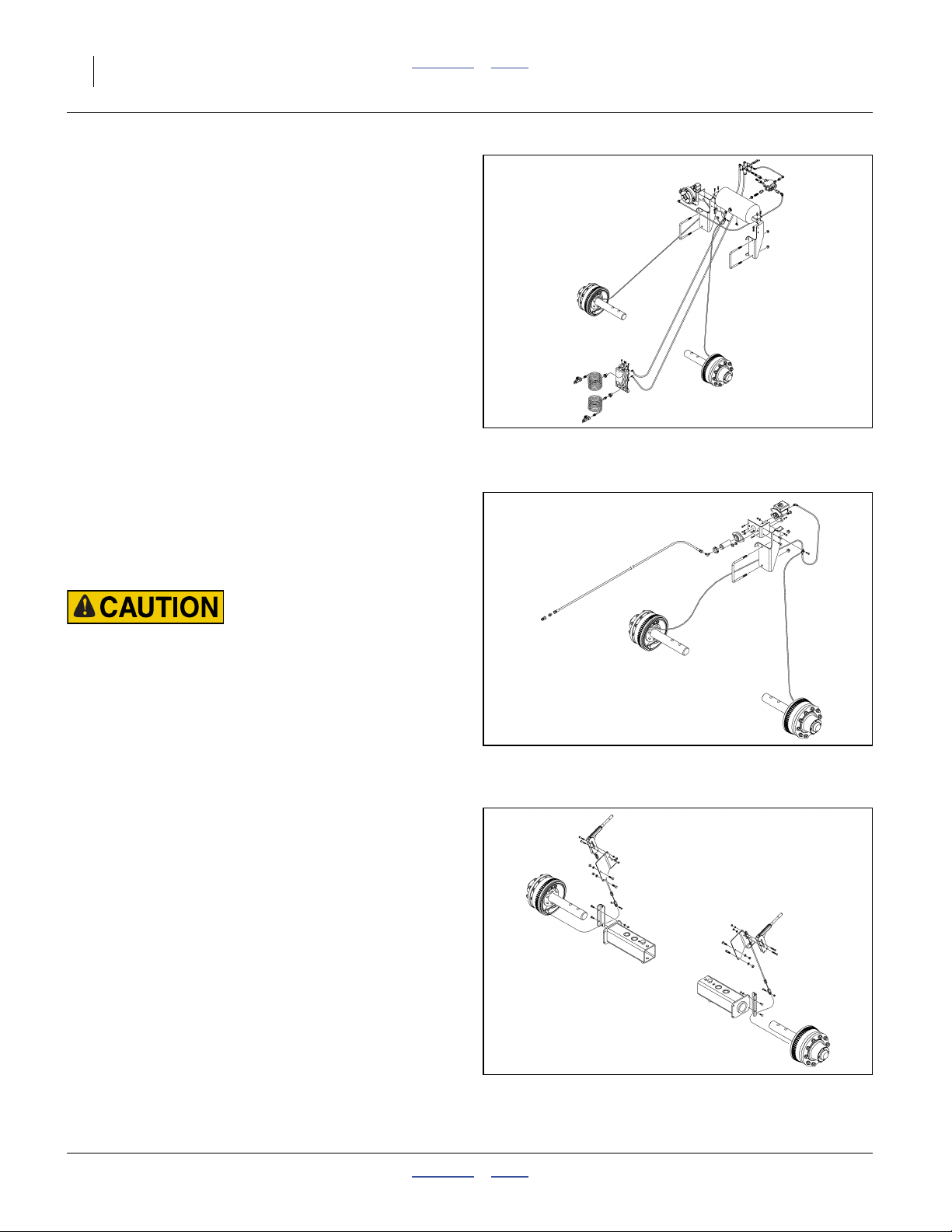
Brake Hookup (Option)
Two air drill braking (trailer braking) systems are available:
• Dual-line air system (Figure 6) with independent cable-
operated parking brake (Figure 8), and
• Single-line hydraulic (Figure 7) with independent
cable-operated parking brake (Figure 8).
In both systems, the tractor’s trailer brake remote port(s)
operate a hydraulic slave cylinder on the drill.
Tractor trailer braking systems are normally integrated
with the tractor brakes, and operate the trailer brakes
when tractor brakes are used during tractor movement.
The trailer braking system may or may not be integrated
with the tractor parking brake system.
Trailer brakes typically are not automatically engaged
when the tractor transmission is in Park, and may not be
engaged by any tractor Emergency Brake.
Both drill systems include an independent cable-operated parking brake on the drill. The tractor cannot
engage or release the drill’s parking brake system.
Null4:
Figure 6
Air Brake System
31227
Braking Hazards:
Make sure the operator understands when drill brakes are
engaged and when they are released (record tractor behavior
on page 41).
Also understand and comply with tractor operational restrictions when trailer brakes are used. For example, it is generally
necessary to inter-tie split brakes, and avoid differential
(steering braking) if trailer brakes are used.
Null4.aac:
Null4:
Null4:
Figure 7
Hydraulic Brake System
Figure 8
Drill Parking Brake System
31232
31224
166-283M Contents Index 04/04/2011
Page 29
Great Plains Manufacturing, Inc. Contents Index Preparation and Setup 25
Air Brake Hookup
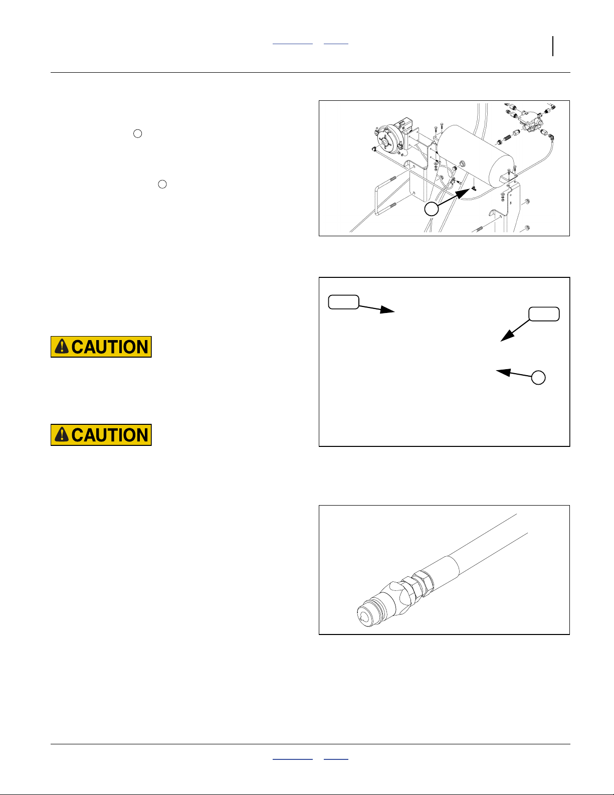
Refer to Figure 9
14. Open petcock at reservoir tank. Drain any water
from tank. Close petcock.
Refer to Figure 10
15. Inspect gladhands before connecting. Clean elastomer seal surfaces . Blow debris out of inlet ports.
Check screen condition.
16. Connect the “Brake”, “Service” or “Control” line first.
This line is Blue-coded.
This line operates the drill brakes.
17. Connect the “Provision” or “Supply” line. This line is
Red-coded.
1
2
1
Null4:
Figure 9
Air Brake Reservoir
31227
The Provision line charges a reservoir tank on the
drill. The Brake line operates a valve system which
meters tank air to the master cylinder on the drill.
Braking Hazard:
Do not use the NTA607HD with a “single-line” air brake system. This drill is designed for transport speeds that require an
air brake system to be “dual-line”. A single-line tractor system cannot charge the tank that powers the drill brakes.
Roll-Away Hazard:
When unhitching, disconnect the red (control) line first. This
sets the brakes on the drill.
Null4:
Hydraulic Brake Hookup
Refer to Figure 11
This is a single hydraulic line, connected to the tractor
“Brake” outlet.
The factory default connector is a3⁄4in poppet-style QD
(Quick Disconnect). If this is incompatible with your tractor, it may be replaced by a connector that mates to, or
can be adapted to:
3
⁄4in male ORB (O-Ring Boss), or
3
⁄4in female JIC (Joint Industry Conference, 37° flare).
Null4:
RED
Null4:
Null4:
Figure 10
Air Brake Connectors
Figure 11
Hydraulic Brake Connector
BLU
2
29646
29647
04/04/2011 Contents Index 166-283M
Page 30
26 Great Plains Manufacturing, Inc. Contents Index NTA607/2007HD
Electrical Hookup
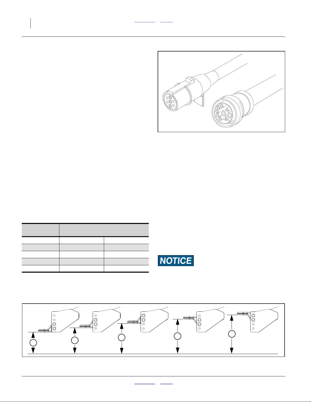
Refer to Figure 12
Make sure tractor is shut down with accessory power off
before making connections.
18. Mate lighting connector to tractor outlet.
19. Mate monitor connector to tractor harness.
20. Mate any optional or aftermarket electrical connectors.
Make connections prior to air drill movement. Some drill
hydraulic circuits are under monitor control.
Null4:
Figure 12
Lighting Connector (European)
and Monitor Connector
Null4:
27172
27080
Heights and Leveling
All frame sections must be at the correct height and level
to maintain even planting depth. The hitch height sets
cart frame level, and must be at a consistent height to
both maintain level, and maintain radar speed calibration.
Periodic frame-leveling adjustments should not be necessary. If you are having problems with uneven depth,
check air drill levelness and follow these procedures.
Hitch
Position
A 38.1 cm 15.0in
B 45.7 cm 18.0in
C 53.3 cm 21.0in
D 61.0 cm 24.0in
E 68.6 cm 27.0in
Hitch Height
Bottom to Ground
Set Tongue Height
Drill must be unfolded for this procedure.
Refer to Figure 13
1. Complete “Bleeding Hydraulics” on page 114.
2. Unfold the air drill fully (page 30).
3. Set the initial tongue height, tractor hitch, and changing implement hitch configuration as necessary. Distance is measured at bottom of hitch to ground level
4. If desired height cannot be attained with normal
range of hitch, hitch may be relocated in tongue bolt
holes. Always have two bolts in use, through two sets
of hitch holes and two sets of tongue holes.
Consistent Seeding Depth Risk:
Level frame in planting conditions. Failure to do so may result
in implement not producing desired results.
A
Null4:
166-283M Contents Index 04/04/2011
B
C
Figure 13
Initial Tongue Height
D
E
31129
Page 31

Great Plains Manufacturing, Inc. Contents Index Preparation and Setup 27
Checking Air Drill Height
The air drill is designed to operate with all sections of the
main tool bar nominally:
65cm (25
planting depth of:
3.8cm (11⁄2in), and a
coulter (option) depth of:
5.1cm (2in).
Refer to Figure 14
Tool bar height is measured to the bottom of the tool bars
on which the row units are mounted.
At the suggested default setting, the implement frame is
level with the ground during planting, and the row units
operate at their most consistent planting depth.
Your crop, soil conditions, disk wear and other factors
may create a need to use a different tool bar height.
Refer to Figure 15
Tool bar height is set via combinations of spacer bushings on the rods of the master lift cylinders ahead of
the implement center section, described on page 81. The
wing end tool bar heights are controlled by slave cylinders that stop retracting when the master cylinders stop.
Only weight transfer adjustment is usually required for
wing height (although eyebolt adjustment is available).
When checking tool bar height:
1. Move the drill to representative planting soil condi-
2. Set hitch to planting height (page 26).
3. Unfold and lower the implement (page 30).
4. Pull forward a meter or so (a few feet) to put openers
5. Check tool bar height across air drill.
6. If center section is not at desired height, see
7. If wing tool bar heights do not match center section,
Marker Setup
Prior to first use, set or review marker extension and tension. See:
•“Marker Adjustments” on page 94.
Prior to each planting session, check and adjust:
•“Marker Disk Adjustment” on page 96.
MetaData: End of “Preparation and Setup”
1
⁄2in) above the planting surface, at a
1
tions.
in ground.
“Adjusting Tool Bar Height” on page 81.
this usually means that wing weight transfer needs to
be set or adjusted. See see “Weight Transfer
Adjustments” on page 85 before considering an
eyebolt adjustment (page 129).
Null4:
Figure 14
31130
Tool Bar Height Check
Measurement Error Risk:
Drill must be fully lowered to field position (with openers into
ground) and hitch height must be set before checking tool bar
height.
1
1
Null4:
Figure 15
Master Lift Cylinder Spacers
31226
04/04/2011 Contents Index 166-283M
Page 32

28 Great Plains Manufacturing, Inc. Contents Index NTA607/2007HD
166-283M Contents Index 04/04/2011
Page 33

Great Plains Manufacturing, Inc. Contents Index 29
Operating Instructions
This section covers general operating procedures. Experience, machine familiarity, and the following information
will lead to efficient operation and good working habits.
Always operate farm machinery with safety in mind.
Pre-Start Checklist
Perform the following steps before transporting the
NTA607HD or NTA2007HD air drill to the field.
High Pressure Fluid Hazard:
Escaping fluid under pressure can have sufficient pressure to
penetrate the skin. Check all hydraulic lines and fittings before
applying pressure. Fluid escaping from a very small hole can
be almost invisible. Use paper or cardboard, not body parts,
and wear heavy gloves to check for suspected leaks. If an accident occurs, seek immediate medical assistance from a physician familiar with this type of injury.
❑ Review “Important Safety Information” on page 1.
❑ Lubricate as indicated at “Lubrication and Sched-
uled Maintenance” on page 132.
❑ Check all tires for proper inflation. See “Tire Infla-
tion Chart” on page 147.
❑ Check all bolts, pins, and fasteners. Torque as
shown in “Torque Values Chart” on page 148.
❑ Check air drill for worn or damaged parts. Repair or
replace parts before going to the field.
❑ Check hydraulic hoses, fittings, and cylinders for
leaks. Repair or replace before going to the field.
Null4:
31131
Master Switch (Option)
This switch is present only if the optional Variable Rate
Kit is installed. The switch is normally located near the
DICKEY-john® console terminal.
The master switch controls the optional linear actuator(s)
on the variable rate gearbox(es). When the master
switch is off, it also signals the seed monitor system that
you are not presently planting.
The master switch and the lift switch control the linear
motor that engages the contact drive, when operating in
GRAN SEED CONTROL or GRAN FERT CONTROL
modes. In GRAN SEED/FERT MONITOR mode, only the
lift switch controls contact drive engagement.
04/04/2011 Contents Index 166-283M
Null4:
Figure 16
Master Switch
29505
Page 34

30 Great Plains Manufacturing, Inc. Contents Index NTA607/2007HD
Unfolding and Folding
Unfold/Fold: Safety Information
Overhead crushing hazard:
Unfold and fold implement only if fold hydraulics are bled free
of air and fully charged with hydraulic oil. Keep away and
keep others away when unfolding or folding.
Electrocution Hazard:
Keep clear of overhead power lines when unfolding, operating,
folding or transporting the air drill. Machine is not grounded.
At higher voltages, electrocution can occur without direct contact. Any line voltage present on implement, cart or tractor can
cause severe injury or death.
Pinch Point and Crushing Hazards:
Keep people away from the drill and tractor during folding.
Risks include pinching or crushing at pivot points and at multiple sites in pivoting assemblies.
Use wing fold locks. If a hydraulic failure occurs, or hydraulic
levers are moved, unlocked wings could fall suddenly causing
a major road accident, or crushing anything near the wings,
resulting in death or serious injury, and property damage.
Falling Hazard - Tires Not a Step:
Do not use tires as steps or platforms. All tires can be in light
ground contact, or free to spin, when implement is lowered.
Wing gauge wheel tires are off the ground in lift.
Unfold/Fold: About the Hydraulics
The fold/unfold (and weight transfer) functions are on a
hydraulic circuit that is shared with the hydraulic fan on
the air cart. The fan must be disabled during fold and
unfold, but is not disabled for weight transfer.
Part of the unfold/fold operation involves the Lift circuit.
To meet highway clearance requirements, the wing
gauge wheels are in the Lowered configuration during
fold, and are moved to the Raised configuration prior to
unfold.
The seed monitor does not need to be active during
unfold. When the implement is raised, with the seed
monitor off, the wing solenoid valves default to Fold circuit enabled.
Wing Tilt Risk:
Fold only on hard level ground. if parked across a slope, wing
lock pins could be difficult or impossible to remove or insert.
Equipment Damage Risk:
Raise implement before unfolding or folding. Folding with
openers lowered causes wing inside rows to dig or drag sideays. Damage is likely.
Null4:
166-283M Contents Index 04/04/2011
Page 35

Great Plains Manufacturing, Inc. Contents Index Operating Instructions 31
Unfold: Summary of Steps
These steps presume a drill raised and folded for transport, such as at initial delivery. Follow the detailed
instructions in step 1 through step 7, beginning on this
page, until this is a familiar operation.
❑ Move to level ground (this page).
❑ Close fan shut-off valve (this page).
❑ Press “Fold Enable” softkey (if displayed).
❑ Fold wings (page 33) to free wing fold locks.
❑ Remove wing fold lock pins (this page).
❑ Perform a Raise operation to deploy gauge wheels
(page 37).
❑ Unfold wings (page 30).
Unfold: Move to Level ground
1. Move the drill to level ground with adequate
overhead and lateral clearances for the fold
operation.
Unfold: Close Fan Shut-Off Valve
Refer to Figure 17
2. Move the valve handle perpendicular to valve
body (fan off).
1
This valve is located at the front of the seed cart, to
the left of the hydraulic fan.
Equipment Damage Risk:
The fan shut-off valve must be closed during unfold and fold
operations. If the valve is open, fan over-speed or seal damage
may result.
Unfold: Retract Fold Cylinders
3. Press “Fold Enable” softkey (if displayed).
4. Retract the fold circuit to lift wings off wing fold lock
pins. Set circuit lever to Neutral (not Float) to hold
wings off pins.
Unfold: Remove Wing Locks
Refer to Figure 18
5. At each wing, remove the wing fold lock pin from the
lock lugs , and secure it in the storage loop .
2 3
Null4:
Null4:
1
Figure 17
Fan Shut-Off Closed for Unfold
31141
2
3
Figure 18
Remove Wing Lock Pin
31139
04/04/2011 Contents Index 166-283M
Page 36

32 Great Plains Manufacturing, Inc. Contents Index NTA607/2007HD
Unfold: Fully Raise Drill
Note: Gauge wheel cylinder locks are provided for main-
tenance, but are not used in typical storage or
transport. Normally, they are not installed at this
time, and do not need to be removed for lowering.
Refer to Figure 19
6. Extend the Lift circuit to:
6a. deploy the wing gauge wheels, and
6b. lift the implement frame slightly at the lock.
Hold the circuit at Extend for a few seconds after the
gauge wheels are fully deployed.
Null4:
Figure 19
Deploy (Lower) Gauge Wheels
31145
Equipment Damage Risk:
Raise before unfolding. If this operation is not performed, the
wing openers contact the ground, drag, and may be damaged.
The center section lift lock may also fail to release during
unfold.
Unfolding: Unfold Wings
7. Unfold the wings by extending the fold cylinders.
Note: One wing may reach the ground before the other. It
is not uncommon for the folding to be slightly
non-symmetrical.
Refer to Figure 20
Hold the circuit at extended for several seconds after the
gauge wheels contact the ground, to ensure that the center lock cylinder activates and disengages the lift lock.
Set circuit to Float or Neutral.
Unfold: Enable Fan
Refer to Figure 17 on page 31
8. Move fan shutoff valve handle to in-line with valve
body.
Null4:
Figure 20
31142
Wing Unfold Progression
Null4:
166-283M Contents Index 04/04/2011
Page 37

Great Plains Manufacturing, Inc. Contents Index Operating Instructions 33
Fold: Summary of Steps
Fold the air drill for moves between fields, transport over
public roads, parking and storage.
Follow the detailed instructions in step 1 through step 12
until this is a familiar operation.
❑ Move to level ground (this page).
❑ Check markers folded (option, page 58).
❑ Clear wing lock lugs (this page).
❑ Fully raise implement (page 37).
❑ Press “Enable Fold” softkey.
❑ Fold wings (page 33).
❑ Install lock pins (page 34).
❑ Lower implement to retract wing gauge wheels for
transport clearance (page 36).
Fold: Check Drill Configuration
1. Make sure markers, if installed, are fully folded
(page 58).
Fold: Move to Level Ground
2. Move the drill to level ground with adequate
overhead and lateral clearances for the fold
operation.
Refer to Figure 21
3. Locate the wing lock pins . Make sure they are not
in the wing lock lugs .
2
3
Fold: Close Fan Shut-Off Valve
Refer to Figure 17 on page 31
4. Move the valve handle ( in Figure 17) perpendicu-
1
lar to valve body. This valve is located at the front of
the seed cart, to the left of the hydraulic fan.
Fold: Raise Drill
5. Extend the lift cylinders to full raise drill. Hold at
raised for a few seconds. Set circuit to Neutral.
Do not install cylinder lock channels.
Fold: Press Softkey
6. If the “Enable Fold” softkey appears on the seed
monitor console, press it. Depending on recent
machine operations, this key may or may not appear.
If it does not appear, Fold is already enabled.
Fold: Fold Wings
7. Activate the fold/tilt/marker circuit to retract the fold
cylinders.
Note: One wing may reach the stop before the other. A
slight asymmetry is not uncommon in folding.
8. When both wings are in contact with their stops, hold
circuit in extend for a few seconds to engage center
section lock cylinder. Set fold/fan circuit to Neutral
(not Float) to hold at folded.
Null4:
Wing Lock Pin and Lugs
Null4:
Wing Fold Progression
3
Figure 21
Figure 22
2
31151
31143
04/04/2011 Contents Index 166-283M
Page 38

34 Great Plains Manufacturing, Inc. Contents Index NTA607/2007HD
Fold: Insert Lock Pins
Refer to Figure 23
9. At each wing, remove the wing lock pin from the
storage loop, and secure it in the lock lugs .
1
2
1
2
Null4:
Fold: Verify Lift Lock
Refer to Figure 24
10. Inspect the center section lift lock to ensure that:
10a. lock cylinder is extended, and
10b. lock lug is below the lock plate post tops .
3
4 5
If the cylinder is extended, but the lock lug is not fully
engaged, Extend the lift circuit to allow the lock lug to
snap into position.
Crush/Pinch Hazards:
Make sure the lift lock is engaged. Lift and re-lower if it is not.
If the lock lug is not fully seated in the lock plate slots, it may
not engage the pull link lug , and the implement will slowly
6
lower after hydraulic power is removed. If anyone is working
on or under the implement, this could result in serious injury
or death.
Null4:
Figure 23
Insert Wing Lock Pin
3
5
6
31152
4
Null4:
Figure 24
31248
Lift Lock Engaged
Null4:
Fold: Tuck Gauge Wheels
Refer to Figure 25
11. Retract the Lift circuit to retract gauge wheels for
transport clearance. Set circuit to neutral to hold
gauge wheels for transport.
Fold: Float Lift Circuit
12. Set Lift circuit to float for transport, parking or storage. Leave Fan/Fold circuit in Neutral.
Null4:
Figure 25
31144
Tuck (Raise) Gauge Wheels
166-283M Contents Index 04/04/2011
Page 39

Great Plains Manufacturing, Inc. Contents Index Operating Instructions 35
Lowering and Raising Air Drill
Lowering/Raising Safety Information
Crushing Hazard During Lowering:
Stay clear of wings and openers during lowering and raising.
Wings are extremely heavy and are driven down with hydraulic
pressure. Coulter and opener disks are sharp. During lowering, openers will cut or crush anything beneath them, and can
cause serious injury or death.
Crushing Hazard While Raised:
Use lift lock (page 34) and gauge wheel lock channels when
working above or beside openers.
Without locks, center section and wings are held up only by
hydraulic pressure, and slowly lower over time. They may
lower more rapidly if the hydraulic system is damaged. They
lower rapidly if the hydraulics fail, or the Lift circuit is set to
Float or Retract.
Shoving Hazard:
Air drill length changes by 56 cm (22in) during raising and
lowering. Injury is possible.
Implement casters and row units move forward during raising,
and backward during lowering. Gauge wheels move forward
during lowering. Casters may swivel. Tractor may move in
some circumstances.
Set brakes / use park to avoid tractor movement. Remain clear
of all tires and row units during raise and lower.
Equipment Damage Risk:
Do not lower while any folding or unfolding operations are
underway or partially complete. Openers can dig in or drag on
ground and be damaged.
Note: Gauge wheel lock channels are provided to hold
the wings of an unfolded implement at the fully
raised position, for maintenance only. These channels are an important safety feature for maintenance, but are not used in normal operations.
04/04/2011 Contents Index 166-283M
Page 40

36 Great Plains Manufacturing, Inc. Contents Index NTA607/2007HD
Lowering
Refer to Figure 26
1. Check that maintenance lock channels are not
installed on gauge wheel lift cylinders.
2. Check that center section lift lock is disengaged. If
not:
• If lock cylinder is extended, check that the fan
shut-off valve is closed (page 31), then perform a
brief unfold operation (Extend the Fold/Fan circuit)
to retract the lock cylinder.
• If the lock cylinder will not retract, perform a brief
Lift operation (Extend the Lift circuit) to free the
pawl. If this fails to disengage the lock, see “Lift
Lock Troubleshooting” on page 100.
3. Unfold drill before lowering (page 30).
4. Make sure all persons are clear of opener sections.
Refer to Figure 27
5. Activate dedicated lift circuit (normally Retract).
Null4:
Figure 26
Lift Lock Disengaged
31249
Falling Hazard:
Do not stand on tires when implement is lowered. Wing gauge
wheels, caster wheels, and seed cart wheels, may have little or
no weight on them, and may turn suddenly and without warning if used as a step, resulting in serious injury.
Null4:
Figure 27
Implement Raised / Lowered
31146
Null4:
166-283M Contents Index 04/04/2011
Page 41

Great Plains Manufacturing, Inc. Contents Index Operating Instructions 37
Raising
Equipment Damage Risk:
Raise the implement for folding and unfolding. If lowered,
inside wing openers drag or dig sideways during fold/unfold,
and damage is likely.
Equipment Damage Risk:
Always raise the implement for tight turns and reverse/backing
operations. Backing with openers lowered causes row unit
plugging, and may cause opener damage. Tight turns with
openers lowered may damage openers near the turn center.
1. Make sure all persons are clear of opener sections.
2. Activate dedicated Lift circuit (normally Extend).
Refer to Figure 28
3. Extend cylinders until all sections are raised. Hold for
a few seconds to re-phase cylinders.
4. Set circuit to Neutral to temporarily hold sections at
raised.
Raising: Center Lift Lock
For convenience during field turns, the center section lift
lock does not automatically engage during lift. The lock
does automatically engage during full fold. To engage the
lock without folding, follow these additional steps:
Refer to Figure 29
5. Verify that all persons are safely clear of implement
sections.
6. Close the fan shut-off valve (page 31).
7. Have an observer stand where the observer can see
the lock cylinder, and the tractor operator can see
the observer.
8. Press “Enable Fold” softkey on seed monitor.
9. Activate the Fold/Fan circuit for folding (typically
Retract). Hold at fold until the observer signals that
the lock cylinder has extended. The lock cylinder
normally extends early in the fold cycle.
10. Gradually move the Fold circuit to neutral, to allow
any wing folding to reverse, by not cause the lock cylinder to retract.
11. Lower the implement until stopped by the lock. This
also prevents the lock from releasing. Set the Lift circuit to neutral.
Note: Gauge wheel lock channels are provided to hold an
unfolded implement at the fully raised position, for
maintenance only. These channels are an important safety feature for maintenance, but are not
used in normal operations.
Equipment Damage Risk:
On tractors with electronic timer controls for hydraulic circuits, lift timers must be set to no more than 2 seconds longer
than needed to fully raise air drill. To reduce oil heating and
system wear, Do Not Set for Continuous Mode.
Regulatory Requirement:
Unless the gauge wheels are in the lowered (tucked) positions
when the drill is folded, the air drill may not meet transport
clearance requirements that apply to your operations.
Null4:
Figure 28
31147
Implement Lowered / Raised
Null4:
Null4:
Null4:
Figure 29
Lift Lock Engaged
31248
Unfolded Lift Lock: Wing Pinch and Crushing Hazards:
The lift lock prevents the center section from lowering, but only
hydraulic oil prevents wings from lowering at the tips. Use
maintenance locks to hold wings raised for extended periods.
See page 105.
04/04/2011 Contents Index 166-283M
Page 42

38 Great Plains Manufacturing, Inc. Contents Index NTA607/2007HD
Transporting the Air Drill
Transport Safety Information
Inadequate Tractor Hazard:
Tractor must weight at least 67% of the drill as towed. Ensure
that the towing vehicle is adequate for the task. Using an inadequate tow vehicle is extremely unsafe, and can result in loss
of control, serious injury and death. See table on next page. Do
not tow if air drill exceeds the load rating of the vehicle.
Check Bridge Loads:
A loaded air drill can exceed the load ratings of bridges you
must cross.
Excessive Speed Hazard:
Maximum transport speed is 30 kph or 20 mph at all times,
and lower with a lighter tractor. Excess speed can result in
loss of control or inability to stop. Reduce speeds with materials loaded, or if road conditions are less than ideal.
Unexpected Wing Tilt-Down and Lowering Hazards:
Use wing fold locks (page 34). Check that implement center
section lift lock is engaged (page 34). Failure to use these
safety features can cause a major accident resulting in death,
injury and equipment damage. If locks are not engaged, and a
hydraulic failure occurs, or a circuit is unintentionally set to
Float, wings can unfold to ground contact, or implement can
settle into ground contact.
Loss of Control Hazard, Tires:
Inflate tires to factory specifications. Tighten wheel nuts to
specifications. Under-inflated tires or loose nuts can cause loss
of control. Over-inflated tires or overt-tightened nuts can fail
suddenly and cause loss of control. Loss of control can cause a
major accident resulting in death, injury and equipment damage.
Collision Hazard:
Check lights and reflector regularly. Replace bulbs and faded/
worn/missing decals as required. Use lights in transport.
These features are critical to visibility, particularly with other
drivers unfamiliar with farm equipment or not expecting to
encounter a slow-moving vehicle.
Note: An installation of optional brakes on the drill does
not reduce tractor capability requirements or
increase allowed maximum transport speed.
166-283M Contents Index 04/04/2011
Page 43

Great Plains Manufacturing, Inc. Contents Index Operating Instructions 39
Tractor Requirements
The figures in the table below represent a limited number
of configurations. The weight of your air drill can vary by
hundreds of kilograms, even if it is the same base model,
due to installed options and/or aftermarket equipment.
If your tractor weight or capability is in question, take
your empty air drill to a scale and get a precise weight.
Null4:
31153
Transport Checklist
❑ Plan the route. Avoid steep hills. Keep clearances in
mind. Folded, your NTA607/2007HD Drill is nearly
4m (13ft) high and is 3m (9.75ft) wide.
❑ Hitch.
Make hydraulic, electrical and optional braking connections. See “Hitching Tractor to Air Drill” on
page 22.
❑ Close hopper lids (page 43).
❑ Check that ladders (page 42) and markers (page 58)
are stowed.
❑ If unfolded, raise, fold and lock.
See “Fold: Summary of Steps” on page 33.
❑ If drill is equipped with optional brakes:
With tractor in Park, and with tractor parking brake
set, release drill parking brakes (page 40).
❑ Always have lights on for highway operation.
❑ Comply with all national, regional and local safety
laws when traveling on public roads.
❑ Release all brakes and travel with caution.
Material may be loaded prior to travel, but increases stopping
distance, increases the need for caution in turns and braking,
and increases tire and brake wear.
Typical NTA607/2007HD Drill Weights
NTA607HD NTA2007HD
Configuration -3275 -4006 -3275 -4006
Typical¹ single 150bu, empty
Typical¹ single 150bu, full seed load
Typical¹ single 82bu, liquid fertilizer, empty
Typical¹ single 82bu, liquid fertilizer, full
Typical¹ dual 82bu, empty
Typical¹ dual 82bu, full seed & dry fertilizer
¹ Includes: Markers, Coulters, Standard Flex, Single-shoot, 2x13 Openers, 3 sets of ballast weights.
Null4:
04/04/2011 Contents Index 166-283M
9800 kg 10500 kg 21700 lbs 23100 lbs
13900 kg 14600 kg 30700 lbs 32100 lbs
10000 kg 10600 kg 22000 lbs 23400 lbs
14400 kg 15000 kg 31700 lbs 33100 lbs
10000 kg 10600 kg 22000 lbs 23400 lbs
15000 kg 15600 kg 33000 lbs 34400 lbs
Page 44

40 Great Plains Manufacturing, Inc. Contents Index NTA607/2007HD
Brake Operation (option)
Cart wheel brakes are optional. There are brake shoe
pairs on each of the two cart wheels. The shoe pairs are
operated by two independent systems:
1. The “service” or “trailer brake” system is controlled
by the tractor. It is connected to the tractor with a single hydraulic line or two air lines.
2. The “parking” or “emergencya” brake system is controlled by latching handles on either side, connected
by cables to the brake shoes for that drill side.
See also:
page 24 - “Brake Hookup (Option)”
page 101 - “Brake Troubleshooting (Option)”
page 118 - “Brake Maintenance (Option)”
Brake Roll-Away Hazard:
Set manual drill parking brake handle before unhitching drill.
Block tires if brakes are not installed, and for extra safety in
case brake system is tampered with or is not in working order.
Parking jack is not sufficient restraint for a drill parked on unlevel ground. An unsecured drill could roll away, causing an
accident resulting in death, injury and substantial property
damage.
Both versions of the trailer brake system to the tractor are
spring-release on the cart. Unless the cart parking brake is set,
cart service braking is released shortly after unhitching the
cart.
Parking Brakes
Cable-operated parking brakes engage and release
independently of the service brake system. There is one
operating handle inboard of each cart transport wheel.
The parking brakes themselves are independent systems for each side of the cart. None of these three braking systems can engage or release any of the others.
Refer to Figure 30 and Figure 31
To engage cart parking brakes, pull each handle, on
each side, up, until the over-center action holds the brake
engaged.
To release cart parking brakes, first make sure tractor
brakes are set (or wheels are blocked, or implement is
lowered), then pull the handle, on each side, downward,
and release forward.
If a handle fails to remain in the engaged position, there
may be insufficient tension on the brake cable. See
“Hand Brake Maintenance” on page 118.
1
Null4:
Figure 30
Parking Brake Engaged <<<<<<<<
>>>>>>>> Parking Brake Released
Machine Damage Risk:
Make drill parking brake release part of your transport checklist. The tractor cannot release the drill parking brakes. Transporting with drill parking brakes set will result in tire or brake
system damage.
Null4:
Figure 31
Parking Brakes Released
29589
31194
a. The parking brake system is not a true emergency brake system, as there is no safe way to set the cable-operated brakes when the
cart is in motion. This manual therefore refers to it only as a Parking brake system.
166-283M Contents Index 04/04/2011
Page 45

Great Plains Manufacturing, Inc. Contents Index Operating Instructions 41
Service Brake Operation
If optional brakes are installed and connected, the
hydraulic/hydraulic or air/hydraulic systems automatically
work in conjunction with the tractor’s own brakes.
Application and release of tractor brakes during tractor
motion applies and releases the service brake system on
the drill.
Know Your Tractor Systems:
Application of tractor Parking and/or Emergency brakes may
or may not operate the drill service brake system, depending
on the design of the tractor systems.
Consult your tractor manual for details on when remote
brake ports are engaged and released. Note any variance from general behavior in the table at right. Make
sure the tractor operator knows when drill brakes are
engaged and released.
Null4:
Single-Line Hydraulic Brake Operation
In this system, a single hydraulic line from the tractor
operates a de-intensifier cylinder on the drill, which is
2
coupled to the drill master cylinder . The drill brake
hydraulic lines are separate from the tractor’s line.
With the hydraulic/hydraulic system, braking is immediately available when the tractor hydraulic system is
active.
Dual-Line Air/Hydraulic Brake Operation
In this system, the “supply” (yellow or blue coded) line
charges a reservoir air tank on the drill. The “service”
(red coded) line meters air from the reservoir to a
booster cylinder , which operates the drill’s hydraulic
brake lines .
Null4.aac:
6 5
7
8
5
Service Air Brakes Not Instantly Available:
Prior to movement, wait for the tractor air system to reach full
charge after drill hookup. Tractor and drill reservoir tanks
must be pressurized. Drill service braking may not be immediately available upon tractor hookup with the air/hydraulic system.
1
3
4
Null4:
Tractor
Braking-
Related Event
Normal tractor
braking
Differential tractor braking
Tractor Parking
Brake
Tractor Emergency Brake
Tractor transmission to Park
1
Null4:
Hydraulic/Hydraulic Brakes
7
Typical Trailer
Brake Port
Response
Activates trailer
brakes
Reduced trailer
braking
Activates trailer
brakes
No effect on
trailer brakes
2
Figure 32
6
4
8
Record How
Your Tractor
Operates
3
31232
5
Null4:
Figure 33
Air/Hydraulic Brakes
04/04/2011 Contents Index 166-283M
31227
Page 46

42 Great Plains Manufacturing, Inc. Contents Index NTA607/2007HD
Ladder Operations
Ladders are provided on the left and right ends of the
cart walkboard for material loading and routine lid/hopper
maintenance. These ladders pivots vertically, and are
held in the raised position by a spring-loaded pin.
Ladder Safety Information
Falling Hazard:
Never allow riders on the walkboard. Use only the ladders to
ascend the cart. Always face the cart when ascending or
descending the ladder. Use the handrails. If only one side of
the cart is used for access, leave the other ladder in the raised
position (as a railing). Make sure raised ladders are latched. A
fall from the ladder or walkboard could result in serious injury
or death.
Regulatory Requirement:
Raise and latch ladders for transport. Lowered ladders may
not meet highway clearance requirements that apply to your
operations.
Deploying Ladder
Refer to Figure 35
1. Use one hand to hold the ladder up, while pulling
horizontal pin to the right.
1
Refer to Figure 34
2. Carefully swing ladder out and down.
Using Ladder
1. Ascend and descend the ladder while facing the drill.
2. Use the handrails when on the higher steps.
Overhead Ladder Hazard:
Make sure horizontal pin at ladder left, near pivot, is fully
engaged when ladder is in the raised position. If the ladder is
not pinned in the raised position, it could swing down and
strike someone, or pinch a hand or arm, resulting in serious
injury. Always check the horizontal capture pin if you did not
personally set it when raising the ladder.
Null4:
Figure 34
31154
Ladder Lowered and Raised
Raising Ladder
1. Swing the ladder up. The pin engages automatically,
and does not need to be held open.
2. Check that the tip of the pin is visible at the out-
1
side of the ladder frame.
Null4:
166-283M Contents Index 04/04/2011
1
Figure 35
Ladder Latch Pin Engaged
31155
Page 47

Great Plains Manufacturing, Inc. Contents Index Operating Instructions 43
Hopper and Tank Lid Operations
Hopper Lid Operation begin on this page.
Tank Lid Operation begins on page 45.
Related Topics
“Loading Materials” on page 47
“Unloading Materials” on page 108
“Material Clean-Outs” on page 109
Hopper Lid Safety Information
Entrapment and Rapid Suffocation Hazard:
Never enter a hopper for loading, unloading or routine maintenance. Leave strainer in place except when instructed to
remove it. Keep lid tightly closed during operations. Keep lid
locked closed or, during storage, locked slightly open. Store
ladder to discourage access to lid area. Keep children away
from drill.
▲ A hopper that is full, or merely appears full, can be an
entrapment hazard. You can sink entirely into the grain, or
into an oxygen-deficient void, and suffocate in a matter of
seconds. Grain bridges and crusts are especially dangerous.
▲ When hazardous fumes or low oxygen levels are present,
you can be quickly overcome even in an empty hopper with
the lid open. There may be no odors to alert you to the hazard.
Blowing Debris and Inhalation Hazards:
Turn off fan before opening hopper lids. Wear eye protection
and dust mask or respirator. Hoppers are mildly pressurized
and air is circulating in the hopper when the fan is running.
Opening a lid with the fan running can expose you to blowing
seed, fertilizer and treatment chemicals. Even with the fan off,
adding seed or fertilizer will create a dust cloud. Risks include
exposure to hazardous chemicals, lung and eye irritation.
Planting Consistency Risk:
Check lid seals for damage at frequent intervals. Check that
latch closes lid tightly. Check hopper pressure reported by the
seed monitor. Avoid metering problems caused by air leaks.
Air leaks can cause irregular metering of materials.
Hopper Lid Operation
Keep lids closed. Keep tightly closed for operations.
Keep loosely closed for storage. Open only for material
loading, hopper clean-out and exceptional maintenance.
Null4:
04/04/2011 Contents Index 166-283M
Page 48

44 Great Plains Manufacturing, Inc. Contents Index NTA607/2007HD
Hopper Lid Opening
Refer to Figure 36
1. Lift handle .
1
Refer to Figure 36 and Figure 37
2. Swing handle out until hook releases from
U-bolt shackle .
3. Move hook clear of U-bolt and re-close handle.
1 2
3
2
3
1
Refer to Figure 37
4. Lift lid slightly at pivot end to clear strainer .
4
5. Swing lid away from strainer. Open only enough to
accomplish the present task.
Inspect Strainer and Hopper
Each hopper is equipped with a strainer intended to:
• capture large foreign matter in seed and materials,
• prevent entry by animals if lid left open, and;
Null4:
Figure 36
Hopper Lid Latched
31156
• discourage hopper entry by children.
Leave the strainer in place except during strainer and
hopper cleaning.
3
4
Refer to Figure 37
6. Each time the lid is opened, inspect the strainer for
debris, and if clear, inspect the hopper itself.
7. If the strainer needs to be removed for cleaning, do
2
not perform these steps until immediately ready to
clean the strainer and return it to the hopper:
• Wear gloves suitable for protection against recent
fertilizers or seed treatments.
Null4:
Figure 37
Hopper Lid Open
26345
• Fully open the hopper lid.
• Lift the strainer out of the hopper.
• Immediately close and latch the lid (below).
• Clean and dry the strainer.
• Return it to the hopper.
Lid Closing
Refer to Figure 37
1. Swing lid over opening until capture hook is centered on U-bolt shackle.
2. Open handle and engage hook on shackle .
3. Close handle for operations or short-term parking.
3
1 2 3
1
For long-term storage, do not engage hook or latch
handle, to avoid deforming the seal.
4. For storage, particularly unlatched, a padlock
through both U-bolts deters unauthorized entry by
persons unaware of possible confined space risks,
and prevents entry of pests, debris and precipitation.
Null4:
166-283M Contents Index 04/04/2011
2
Page 49

Great Plains Manufacturing, Inc. Contents Index Operating Instructions 45
Tank Lid Operation
Liquid fertilizer is customarily loaded from below the tank
via the quick-fill inlet, but may also be loaded from above
with the lid removed.
Do not open the lid while a quick-fill operation is already
in progress. The lid is vented, and will be releasing vapor
from the tank. At higher inlet rates, the tank may also be
mildly pressurized, and removing the lid could expose
you to sudden high concentrations of vapor.
Refer to Figure 38
Wear chemical gloves. The underside of the lid is likely to
be damp or wet, and coated with whatever chemicals
have been used.
a
Wear a mask or respirator. Consult the MSDS
for the
materials recently used, or material to be loaded.
Null4:
Figure 38
Tank Lid Open
31390
Null4:
a. MSDS - Material Safety Data Sheet, available from the material supplier.
04/04/2011 Contents Index 166-283M
Page 50

46 Great Plains Manufacturing, Inc. Contents Index NTA607/2007HD
Meter Doors
Refer to Figure 39 and Figure 40
Each meter box has two distinct access doors on the bottom:
1
• On the air outlet (rear) side: Clean-Out
(for emptying hopper)
2
• On the air inlet (front) side: Calibration
(for meter sampling and meter clean-out)
The doors are closed during transport, loading and planting. They may be open slightly in storage to allow drainage of condensation.
The doors need to close and seal tightly during planting.
Periodically inspect the lever clamps for proper tension,
and inspect the elastomer seals for integrity and resiliency.
Meter Door Opening
1. Lower the meter chute. Push the latch back
(toward cart center). Pull the outside end of the
chute to the outside and down.
2. There are two clamp handles on each door. Pull out
on a clamp handle just until it is loose.
3
3. Pull out on the other clamp handle. The door normally will swing down on its own. If not, pull it open
by hand.
4
Meter Door Closing
Make sure the clamp handles are out or down (not up),
or it will not be possible to close the door.
1. Use a clean rag to wipe any residual material from
the face of the elastomer seals on the door, and from
the bottom face of the meter box.
2. Swing the door up into closed position.
3. While holding the door closed, swing one clamp handle up, past vertical.
4. Swing the other clamp handle up past vertical.
5. Inspect the door closure for possible air leaks.
Replace any deformed elastomer seal or damaged
latch clamp.
6. Raise the meter chute. Pull it away from cart center.
Engage the latch handle under the washer.
3
Null4:
2
1
Figure 39
Null4:
Null4:
Meter Doors Open
Material Loss / Air leak Risks:
Do not open the clean-out door (the rear door at the air outlet
side) until preparations have been made to capture any material to be re-used. Any material present will flow immediately,
possibly in large volume, as soon as the door is open. It may be
impossible to close the door, with an adequate air seal, until
the hopper is empty.
3
4
31161
Null4:
Figure 40
31158
Meter Doors Closed
166-283M Contents Index 04/04/2011
Page 51

Great Plains Manufacturing, Inc. Contents Index Operating Instructions 47
Loading Materials
1. Take appropriate precautions for handling materials.
Whether using auger or hand-loading, dust is likely.
Review Materials Safety Data Sheets (MSDS).
2. Review hopper lid safety information on page 43.
3. The implement does not need to be in any particular
configuration for material loading. Raising it, however, does reduce the hitch load.
Loading Material Safely
Entrapment and Rapid Suffocation Hazard:
Never enter a hopper for loading or unloading.
▲ A hopper that is full or merely appears full can be an
entrapment hazard. You can sink entirely into the grain, or
into an oxygen-deficient void, and suffocate in a matter of
seconds. Grain bridges and crusts are especially dangerous.
▲ When hazardous fumes or low oxygen levels are present,
you can be quickly overcome even in an empty hopper with
the hopper lid open.
Agricultural chemicals can be dangerous, including treatments
on seeds and components of fertilizers. Improper use can seriously injure persons, animals, plants, soil and property.
▲ Read and follow chemical manufacturer’s instructions.
▲ Wear protective clothing.
▲ Handle all chemicals with care.
▲ Avoid inhaling smoke from any type of chemical fire.
▲ Store or dispose of unused chemicals as specified by chemi-
cal manufacturer.
▲ Dispose of empty chemical containers properly. Laws gen-
erally require power rinsing or rinsing three times, followed
by perforation of the container to prevent re-use.
Loading: Do Not Enter Hoppers
With material present, and once used for hazardous fertilizers, or seeds with hazardous treatments, your hoppers may become
“permit-required confined spaces”
under applicable statutes, regulations, insurance rules or
business policy. The venting tube structure in the hoppers has rungs for escape, and is not an entry ladder.
Loading: Check Strap Tension
4. Check hopper strap tension prior to every material
load on a new drill, and again after material is
loaded. See page 106.
Null4:
04/04/2011 Contents Index 166-283M
Page 52

48 Great Plains Manufacturing, Inc. Contents Index NTA607/2007HD
Loading Seed or Dry Fertilizer
Loading: Use a Tractor
5. Securely hitch drill to a tractor with adequate weight
and power. Park drill on solid, level ground. See
Tractor Requirements, “Specifications and Capaci-
ties” on page 144. If a suitable tractor is not available, ensure that the tongue jack is on solid ground,
and block multiple tires.
6. Lower the ladder on one side (page 42).
Loading: Select Hoppers to Use
Refer to Figure 41
Single-Hopper Configuration
For single-hopper drills, all materials are delivered to the
row unit seed tubes, and are placed in furrow.
Dual-Hopper Single-Shoot Configuration
On a dual-hopper “single-shoot” drill, either hopper may
be used for seed and/or fertilizer. All materials are delivered to the row unit seed tubes, and are placed in furrow.
If applying the same material from both hoppers, you can
meter from both simultaneously, or from one at a time,
sequentially. For sequential metering, the unused hopper
is disabled by removing a final Range gear.
Simultaneous metering avoids weight imbalance and
eliminates stopping before the halfway point for meter
change-over. However, avoid simultaneous metering if it
would result in a Low Range variable rate gearbox setting below a scale value of 20.
If metering simultaneously, set each meter for one half
the chart (or calibrated) rate. Do not merely use half the
single-meter scale setting, as this is usually not half the
rate. See “Setting Material Rates” on page 65, and the
Seed Rate Manual for more details.
Dual-Hopper Double-Shoot Configuration
Hopper Intended Hopper Use
I (Left) Seed or In-Furrow Dry Fertilizer
II (Right) Dry Fertilizer or Broadcast Seed
Variable Hitch Load:
Loading materials increases the hitch load. With the implement lowered, and its circuits in Float, a full material load
results in a hitch load of nearly 1900 kg (4200 pounds). This
results in a jack load of up to 25 kg/cm2 (350 psi). Even if
current dry ground supports the jack, sudden wet weather
could result in the jack becoming mired.
Single
Single
Hopper
Shoot
II
I
Note: Towers are omitted from illustrations.
Double
Hopper
Double
I
Shoot
II
On a dual-hopper “double-shoot” drill, the factory default
configuration is that the hoppers and delivery hose routing are optimized for specific uses. See table above.
Augering Heights
Hopper Elevation to Flange
2890 liter (82 bu) 2.83m (9 ft. 0 in.)
5290 liter (150 bu) 2.97m (9 ft. 1 in.)
Null4:
166-283M Contents Index 04/04/2011
Null4:
Figure 41
Hopper Material Delivery
31163
Page 53

Great Plains Manufacturing, Inc. Contents Index Operating Instructions 49
Loading: Air-Out System
Refer to Figure 42
7. At each empty hopper to be loaded, if meter box
clean-out door or calibration was completely closed,
open it. See “Meter Doors” on page 46.
8. If any doors are fully or partially open, wipe seals
Material Mis-Application Risk:
Before filling the drill for the first time, and at the beginning of
each season, check the entire bin for leaks. A small air leak
can cause large variations in seeding rates.
and meter bottom flanges clean. Close and latch
doors.
9. If the drill has been parked for more than a day, condensation may have caused moisture to accumulate.
Whether or not meter doors are opened, run the fan
system for several minutes to blow moisture out of
the meters, primary and secondary seed hoses.
10. With the fan running, check hopper-lid and meterbox seals carefully for air leaks. Adjust bin latch or
replace seals to prevent leakage.
Loading: Prepare Hopper(s)
11. Shut off all hydraulic power to the drill (unless using
a tractor or cart circuit for an auger).
12. Open lid of hopper to be loaded (page 43).
13. Check that the strainer basket is in place in the top of
the bin. Remove any foreign material from basket.
Null4:
Figure 42
Close Meter Doors
31158
Loading: Load Seed or Dry Fertilizer
14. Load material at open hopper lid.
15. Check the strainer periodically for foreign matter.
If markers are not installed on the implement, circuits
A&B are available at the left rear of the cart, and may be
Marker
Circuit
Receptacles
(A & B)
used for auxiliary purposes, such as a user-provisioned
auger. Auger height required is:
3.0m (9.8 ft) for 5290 liter (150 bu) hopper, and
2.8m (9.3 ft) for 2890 liter (82 bu) hoppers
Loading: Close-Out
16. Remove any foreign matter from the strainer basket.
17. Wipe any grain or foreign matter from lid-seal area
on top of hopper bin. Close lid(s) and latch securely.
18. Return ladder to storage/transport position
(page 42).
Null4:
Null4:
Null4:
Figure 43
Cart Hydraulic Panel
848-562c
Planning Re-Loads
The seed monitor has a level sensor in each hopper to
warn when seed box is empty. Alerts occur at these
approximate levels of remaining material:
82bu hopper: 25 liters (0.7 bu)
150bu hopper: 25 liters (0.7 bu).
Entanglement and High Pressure Fluid Hazards:
Never operate an auger without guards. Wear gloves and eye
protection when making/breaking auger hydraulic connections. Follow all auger manufacturer instructions for safe
auger operation.
04/04/2011 Contents Index 166-283M
Page 54

50 Great Plains Manufacturing, Inc. Contents Index NTA607/2007HD
Loading Liquid Fertilizer (Option)
Agricultural Chemical Hazards:
Avoid contact with skin or eyes. Wear proper protective equipment as required by chemical manufacturer. Avoid prolonged
breathing of chemical fumes. Wear respirator as required by
chemical manufacturer. Some chemicals will cause serious
burns, lung damage and death. Seek medical assistance immediately if accident occurs. Know what to do in case of an accident.
Tongue Weight Hazard:
Hitch to tractor, or ensure that tongue jack is on an adequate
surface. Filling the liquid fertilizer tanks adds nearly 2200 kg
(4800 pounds) to the cart, much of which may be borne by the
tongue. On soft ground, or in the event of sudden rain, the
parking jack could sink into the ground.
Inconsistent Rate Risk:
Use only pre-mixed liquid fertilizers. If using a pre-mixed fertilizer that tends to separate, sediment or stratify, load only
immediately before use. The tanks of the optional liquid fertilizer system do not include agitators.
Tank Loading: All Methods
Tank fill level is reported by a sight gauge on each tank.
The table at right converts the scale levels to liters.
Refer to Figure 44 on page 51 and Figure 143 on page 161
1. Hitch cart and set tractor parking brakes. If filling
unhitched, make sure that tongue jack is on an adequate surface. Block cart tires or set optional cart
brakes.
2. Close quick-fill shutoff valve at cart right.
3. Close cart outlet valve at cart rear.
12
22
4. Determine the desired application rate. Select and
installed suggest drop-line orifice plates (see
26
Seed and Fertilizer Rate Manual).
5. Close shut-off valve at pump.
6. If the strainer has not been serviced recently, per-
16
17
form that maintenance before loading material
(page 107).
7. Open both tank discharge valves , unless filling
13
only one tank at a time, in which case close the valve
for the tank not being filled.
.
Metric Equivalents: 200 Gallon Tank Scale
Gallons Liters Gallons Liters Gallons Liters
200 755 125 475 50 190
175 660 100 380 25 95
150 570 75 285 15 55
31169
Note: With both tank valves open, any type of filling oper-
ation fills both tanks. At high fill rates, or if the drill is
parked across a slope, tank filling may be uneven.
Null4:
166-283M Contents Index 04/04/2011
Page 55

Great Plains Manufacturing, Inc. Contents Index Operating Instructions 51
Tank Loading: Quick-Fill
Complete step 1 through step 7 on page 50.
8. Check that tank lids are secure.
9. Connect the source supply line to the quick-fill
11
inlet .
10. Open any shut-off valve at the source outlet line.
13
22
11. If the source is pumped, start the pump.
12. Open the cart inlet valve .
13. Observe the sight gauge (not shown) on the
tank(s) being filled. Do not fill above the
12
15
16
12
“200” (gallon) mark.
14. Close the source outlet shut-off valve, and if none,
close the cart inlet shut-off valve .
12
17
15. Stop the source pump (if any). Close the cart inlet
shut-off valve if not already closed.
16. Unless already at the field, close both tank discharge
valves to prevent tank-to-tank transfers during
13
transport.
12
Null4:
Figure 44
11
31372
Quick-Fill Inlet
Tank Loading: Top-Fill
Complete step 1 through step 7 on page 50.
17. Deploy the ladder(s) as needed for access to the
tanks (page 42).
Refer to Figure 45
18. Unscrew the lid on the tank to be filled.
1
1
19. Fill the tank. If filling both tanks from one tank, allow
time for the levels to balance.
20. Observe the sight gauge on the tank(s) being filled.
Do not fill above the “200” (gallon) mark.
21. Screw on lid. Return ladder to storage/transport
position.
Null4:
Figure 45
31390
Tank Lid Open for Filling
Null4:
04/04/2011 Contents Index 166-283M
Page 56
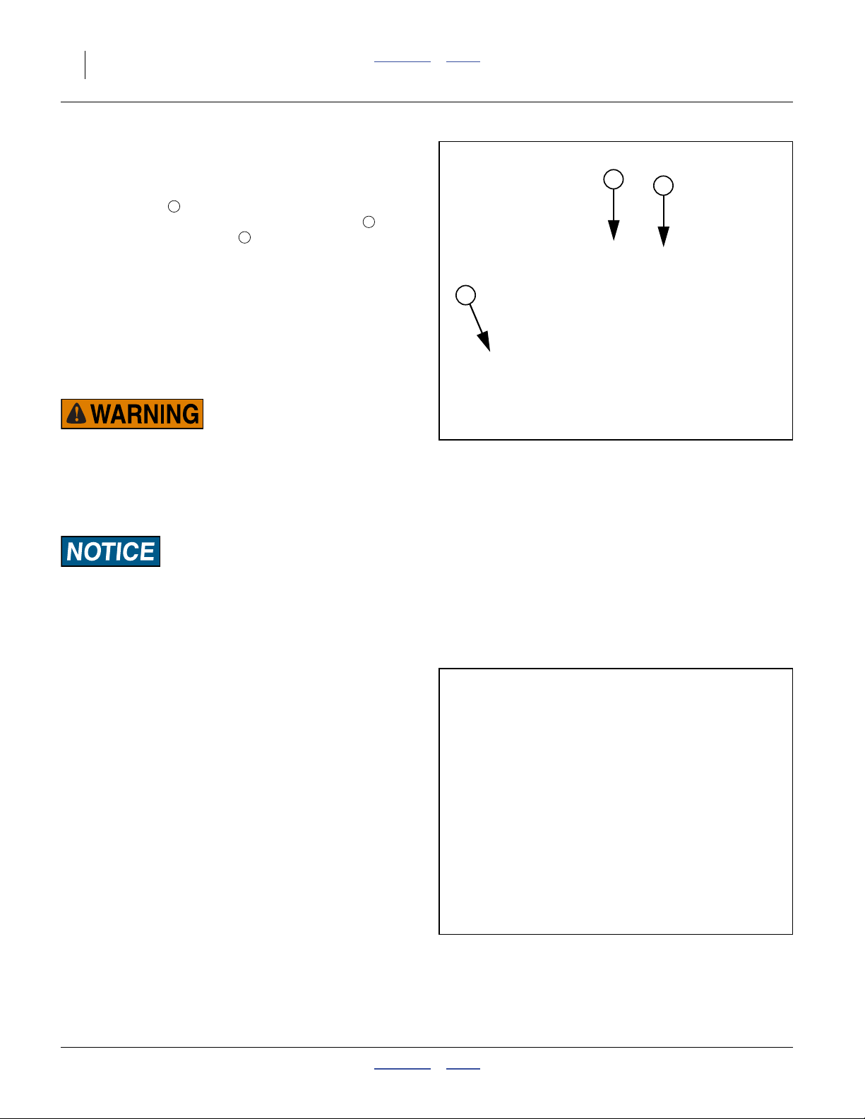
52 Great Plains Manufacturing, Inc. Contents Index NTA607/2007HD
Calibration Crank, Bag and Scale
Refer to Figure 46
Under the right end of the walkboard, the drill includes a
calibration crank , calibration bag, and digital scale.
The bag and scale are stored in a compartment , held
closed by the crank. A hook is provided for weighing.
1
2
3
The hand crank is provided for manual operation of the
meters (the meters otherwise turn only when the drill is
lowered and in motion). The crank is used for two common tasks:
• calibration of the meter setting for planting, and
• clean-out of the meter flute chamber.
Calibration Crank Safety Information
Moving Chain Hazard:
Keep all persons except operator away from drill mainframe
during crank operations. Body parts and clothing can get
caught in chains, sprockets and gears, causing serious injury.
When operating the crank, all parts of the contact drive system
are in motion, including parts out of sight of the operator.
Machine Damage / Invalid Results Risks:
Rotate the hand crank only in the counter-clockwise direction.
Operating in reverse can damage the meter gear box, and
produces low sample sizes leading to incorrect calibration and
excessively high field rates.
Null4:
1
2
3
Figure 46
Hand Crank in Storage
31170
Operating the Hand Crank
1. Turn on the seed monitor. This step is required if the
Variable Rate option is installed.
2. Raise drill (page 37). This prevents the contact drive
wheel from engaging the transport tire.
Note: Although the crank can be operated with the con-
tact drive engaged, it requires extra effort to override a ratchet coupling.
Refer to Figure 47 (note: Figure 47 exaggerates size of cranking directional decal)
3. Un-pin crank from storage location, and place over
hex shaft at cranking location (right side of cart,
between rear-most gearbox and transport wheel).
4. For meter clean-out, set both meters 80 or higher
(LOW range), or 10 or higher (HIGH RANGE).
For calibration, set the final Range gears, and the
meter under test per the instructions in the Seed
Rate Manual, and remove a DRIVER or DRIVEN
final Range gear on the other meter.
166-283M Contents Index 04/04/2011
Null4:
Null4:
Null4:
Figure 47
Hand Crank Operation
31171
Note: During clean-out, if a variable rate gearbox is set to
“0”, operating the hand crank may fail to clear the
meters of seed.
Page 57

Great Plains Manufacturing, Inc. Contents Index Operating Instructions 53
Refer to Figure 48
5. Lower the meter chute. Push the latch back
4
(toward cart center). Pull the outside end of the
chute to the outside and down.
6. Open calibration door (front door, at air inlet side)
5
on meter(s) being calibrated. See page 46 for door
operations.
Material Loss Risk:
Open only the calibration door (front, meter air inlet side).
Do not open the clean-out door (rear door, meter air outlet
side) or material will flow in large quantities. It is generally
not possible to re-close the clean-out door, with sufficient air
seal, until the hopper is empty.
Refer to Figure 49
7. For calibration, remove calibration bag and
7
scale from storage compartment.
5
Note: The empty bag weighs 0.91 kg (2.00 pounds).
Refer to Figure 50
8. Hook bag to chute of meter under test. Place loops
over ears at outside end of chute. Place hooks in
chute latching slots.
9. Turn the crank until material is flowing to the bag.
Stop. Sweep any material in the chute into the bag.
Empty the bag.
10. Turn the hand crank, counter-clockwise, to simulate
meter operation for1⁄10ha or1⁄10ac.
Specific recommendations may be made in applicable
manual sections. See:
see “Meter Calibration” in the Seed Rate manual,
see “Unloading Materials” on page 108, and
see “Storage” on page 63.
In general, you may operate the crank as fast as is comfortable. For reference, at a field speed of 10 kph
(6.2 mph), the jackshaft rotates at 90 rpm (11⁄2 turns per
second).
11. Sweep chute contents into bag.
12. Weigh sample:
Attach scale to hook ( in Figure 46 on page 52).
3
Zero scale.
Attach bag to scale.
Weight bag.
Subtract bag weight from result.
13. Wipe the meter calibration door seal and flanges.
Close the calibration door.
14. Return scale and bag to storage compartment at
task completion. Secure compartment door closed
with calibration crank and pin.
Null4:
Null4:
Null4:
5
Figure 48
Calibration Door Open
7
Figure 49
Calibration Scale and Bag
Figure 50
Calibration Bag on Chute
U
F
B
D
4
31159
5
31172
31173
04/04/2011 Contents Index 166-283M
Page 58

54 Great Plains Manufacturing, Inc. Contents Index NTA607/2007HD
Air System Operation
Null4:
Null4.aac:
6
4
8
7
17
16
18
5
2
9
14
15
19
12
10
11
1
Figure 51
Single-Hopper Air System
6
4
8
15
16
17
31324
8
7
17
16
9
2
14
14
9
18
15
12
3
13
1
5
10
Null4:
Dual-Hopper (Double-Shoot) Air System
Null4:
166-283M Contents Index 04/04/2011
Figure 52
11
19
20
31325
Page 59

Great Plains Manufacturing, Inc. Contents Index Operating Instructions 55
Air Systems Overview
1 Hydraulic Fan 8 Hopper Pressure Sensor 15 Distribution Tower
2 Fan RPM Sensor 9 Seed Meter 16 Blockage Sensor
3 Diverter Vane 10 Flute Shaft 17 Secondary Seed Hose
4 Manifold Pressure Gauge 11 Flute Shaft RPM Sensor 18 Tramline Diverter
5 Meter Inlet Manifold 12 Meter Outlet Ports 19 Opener Seed Tube
6 Hopper 13 Single-Shoot Y-Tube 20 Opener Fertilizer Tube
7 Pressure Balance Lines 14 Primary Seed Hose
1. Hydraulic Fan (page 56)
The fan generates the air flow required to deliver
material to the rows. Speed is adjusted via the tractor circuit. Output is monitored via rpm , pressure
gauge and pressure sensor .
5 8
2
2. Fan RPM Sensor (page 82)
The seed monitor reports fan rpm based on this sensor. Although it is accurate for rate, it cannot detect a
fan running in reverse.
3. Diverter Vane (page 84)
Present only on dual-hopper drills, this controls airflow balance between the meters. This may need
adjustment with dissimilar material metering.
4. Manifold Pressure Gauge(s) (page 82)
There is one gauge per hopper, mounted for ease of
observation from the tractor cab. These report
whether or not the air system is within recommended
limits. On dual-hopper systems, the gauges assist in
setting the diverter vane .
3
5. Meter Inlet Manifold (page 84)
Fan air is divided (or further divided) into equal flows
for each meter inlet port .
5
6. Hopper (page 48)
Material (seed or fertilizer) flows into the top of the
seed meter .
9
7. Pressure Balance Lines
Each hopper contains an internal pressure-balancing system to equalize pressure above and at the
base of the material.
8. Hopper Pressure Sensor
This sensor signals the seed monitor, which can
alarm if the hopper pressure goes out of limits. A
dual hopper drill has two sensors.
9. Seed Meter
The meter combines material with air flow. It also has
features for rate Range, calibration and clean-out.
10. Flute Shaft (page 163)
Two (and optionally; three or four) sets of flute “stars”
control the flow of seed from the hopper into the air
streams.
11. Flute Shaft RPM Sensor (page 71)
This shaft encoder provides metering rate data, stoppage alarms, and is used by the optional Variable
Rate Kit to control metering rate.
12. Meter Outlet Ports
Material falls from the meter flutes into the air
10
streams flowing from inlet manifold to outlet ports.
Each port is a separate compartment.
13. Single-Shoot Y-Tube
A two-hopper drill may optionally have the output of
both meters combined into a single stream to a single set of towers. The flows combine at Y-tubes
behind the meters.
14. Primary Seed Hose
Four (single-hopper/shoot) or eight (double-shoot)
hoses deliver seed from the meters to the
towers .
15
9
15. Distribution Tower
The riser tube and distribution rings have features to
evenly divide the primary hose material flow into
multiple secondary hose flows. There are four
17
towers on single-hopper and single-shoot drills, and
eight towers on double-shoot drills.
16. Blockage Sensor
Each tower outlet port has a sensor that detects
material passage and signals the seed monitor. The
primary function of this sensor is to trigger an alarm
on flow stoppage.
17. Secondary Seed Hose
These hoses deliver material from a tower outlet port
to a seed tube or fertilizer tube .
19 20
18. Tramline Diverter (Option, page 142)
19. Opener Seed Tube
Seed from hopper I (and hopper II on single-shoot
drills) is delivered in-furrow ahead of the seed firmer.
20. Opener Fertilizer Tube (page 93)
On a dual-hopper double-shoot drill, the material
from hopper II is delivered to this tube above the
seed firmer and furrow.
04/04/2011 Contents Index 166-283M
Page 60

56 Great Plains Manufacturing, Inc. Contents Index NTA607/2007HD
Fan Operation
Fan Safety Information
Rotating Fan Blade Hazard:
Do not operate fan with guard screen removed. Fan accelerates instantly and with high torque. Body parts and clothing
can be drawn into fan, resulting in death or serious injury.
Disconnect fan circuit at hitch when working on fan.
High Pressure Fluid Hazard, Fan Hydraulic Motor:
Escaping fluid under pressure can have sufficient pressure to
penetrate the skin causing serious injury. Use a piece of paper
or cardboard, NOT BODY PARTS, to check for leaks. Wear
protective gloves and safety glasses or goggles when working
with hydraulic systems. If an accident occurs, seek immediate
medical assistance from a physician familiar with this type of
injury.
Machine Damage Risk: Protect Motor Seals:
Fan circuit has three hoses. All must be correctly connected.
Make sure that “SUMP” line is connected to a tractor port
capable of accepting high volume low pressure return oil.
Connect Case Drain line to a low volume case drain return.
Avoid sudden circuit changes. Motor seals may be damaged by
rapid starts and stops, or by circuit reversals. Engage fan circuit lever slowly, while observing fan rpm on seed monitor.
Dust, Noise and Startle Risks:
Avoid unexpected fan operation. Set fan shut-off valve to OFF
(drill fold) when no fan operations are intended. Set valve to
ON before activating fan hydraulic circuit. If fan does not start
when slowly moving fan/fold circuit lever, set lever to Float or
Neutral and check shutoff valve.
Note: Avoid fan direction reversal. A fan running in re-
verse cannot generate sufficient airflow for planting. If fan cannot reach target rpm, check for
reversed circuit connections or improper drain connection.
166-283M Contents Index 04/04/2011
Page 61

Great Plains Manufacturing, Inc. Contents Index Operating Instructions 57
Fan General Information
The hydraulic fan supplies the air stream that carries
materials from the meters, through the primary hoses to
the towers, then to the secondary hoses to the rows.
The fan needs to be running in the correct direction, and
within a narrow speed range, to reliably deliver material
at your calibrated rates.
The fan shares its hydraulic circuit with the implement
fold/down-pressure/weight-transfer system. This has
several considerations:
• (see decal left panel) The fan is on during field operations, with the down-pressure and weight transfer circuits active. If planting on very uneven ground, you
may observe some minor fluctuation in fan rpm, as the
implement circuits demand oil.
• (see decal right panel) The fan must be shut off during
fold and unfold operations (page 30).
• The fan must be off for calibration (page 52).
• The fan may be on when the implement is folded and
locked (page 33), for air system clean-out (page 109).
Machine Damage Risk:
Always engage the fan with the tractor at a low engine speed.
Engaging the fan when the tractor is at high speed may cause
fan damage.
Do not reverse hydraulic flow with the fan running.
Note: If the fan plumbing or hitch hookup is reversed, air
flow rate will be very low or zero. If you are unable
to reach 3000 rpm, check hose connections.
Note: Fan speed is monitored and reported by the seed
monitor, but is manually controlled. The optimum
rate depends on the seed type and any treatments.
“Fan Speed Suggestions” on page 82 for further
information.
Null4:
Figure 53
Manifold Pressure Gauges
31189
04/04/2011 Contents Index 166-283M
Page 62

58 Great Plains Manufacturing, Inc. Contents Index NTA607/2007HD
Fan Field Operation
1. Unfold the implement (page 30).
2. Set the Fan/Fold circuit lever to neutral.
Refer to Figure 54
3. Set the fan shut-off valve to ON/open.
4. With the tractor engine at low rpm, slowly Extend the
lever for the Fan/Fold circuit. Bring the fan up to recommended speed (page 82). Let the fan warm up for
15 minutes before planting.
5. Lower the drill 1.5 - 3m (5-10ft) before planting is to
begin. It takes a few seconds for seed to travel from
the meters to the rows.
6. Leave the fan running during field turns. Meter drive
is shut off when the openers are raised.
7. At the end of application, raise openers. Stop mate-
Null4:
Figure 54
Fan Shut-Off Valve ON
31176
rial flow before shutting off the fan.
8. Shut off the fan by carefully moving the circuit lever
to Float or Neutral. Avoid moving the lever into
Retract. The fan does not stop instantly. A check
valve in the fan circuit locally recirculates oil until the
blades coast to a stop.
Machine Damage Risk:
Always engage the fan with the tractor at a low engine speed.
Engaging the fan when the tractor is at high speed may cause
fan damage.
Marker Operation (Option)
Dual markers are optional on the NTA607/2007HD. See
“Markers” on page 142 for ordering information.
Additional Marker Topics
See also:
“Marker Adjustments” on page 94, and;
“Marker Maintenance (Option)” on page 130.
Dual markers are on a dedicated hydraulic circuit which
contains an adjustable automatic sequence valve.
Marker circuits must be fully charged with oil and free of
air before operation. Before first use / after maintenance,
perform “Marker Hydraulic Bleeding”, page 130.
Do not reverse hydraulic flow with the fan running.
Note: If the fan plumbing or hitch hookup is reversed, air
flow rate will be very low or zero. If you are unable
to reach 3000 rpm, check hose connections.
Note: Fan speed is monitored and reported by the seed
monitor, but is manually controlled. The optimum
rate depends on the seed type, any treatments.
“Fan Speed Suggestions” on page 82 for further
information.
1
Null4:
Figure 55
Marker Folded, in Cradle
1
31177
166-283M Contents Index 04/04/2011
Page 63

Great Plains Manufacturing, Inc. Contents Index Operating Instructions 59
Marker Safety Information
Electrocution Hazard / Machine Damage Risk:
Never fold implement with a marker extended. Never extend a
marker with implement folded. Operate markers only with drill
completely unfolded. A marker extended when folded is a
major overhead electrocution hazard, overhead clearance hazard, and may damage drill systems.
Sweep and Pinch/Crush Marker Hazards:
Do not allow anyone to stand near or beyond the end of the
wings during marker operations. A folding marker can cause
serious or fatal crushing injuries. Marker disk is sharp. A folding or unfolding marker can cause serious lacerations and
cause falls.
Marker Unfold and Fold
1. Clear the area within 4m (12ft) of marker arms on
both sides of the drill.
2. Carefully move the circuit lever to extend and
observe which marker side is extending.
Refer to Figure 55
3. If the marker extending is not on the desired side,
reverse the lever (to retract) until the marker returns
to the cradle . Set the control to Neutral briefly,
1
then to Extend again. This cycles the sequence
valve and extends the alternate marker.
4. When marker is fully extended, set circuit to Neutral.
5. To fold marker, set circuit to Retract until marker is in
cradle.
6. To extend other side, Extend once more, as at
step 3.
Special Dual-Marker Operations
Passes with same marker side:
• Retract (raise) the marker and make the turn.
• Begin to extend the opposite marker.
• Retract it, and extend the original marker.
Note: Which marker side extends at circuit activation is
somewhat unpredictable, as it depends on the
final state of the sequence valve at last use.
Null4:
Figure 56
31178
Marker Unfolded
Both markers unfolded:
• Fully extend one side.
• Momentarily Retract, then Extend to deploy opposite
side.
04/04/2011 Contents Index 166-283M
Page 64

60 Great Plains Manufacturing, Inc. Contents Index NTA607/2007HD
Field Operations
Final Field Checklists
Use the following tables to develop a final checklist for
your tractor/air drill configuration.
Null4.aac:
Null4:
Mechanical Checklist Page
❑ Check all tire pressures 147
❑ Tongue height preset 26
❑ Implement unfolded 30
❑ Marker extension set 95
❑ Marker disk angle set 96
❑ Check ladders stowed. 42
Null4:
Electrical Checklist Page
❑ Verify electrical hookups solid 26
❑ Check seed monitor terminal and observe
any diagnostic messages
❑ Configure monitor for crop and population a
a. Refer to DICKEY-john® Air Cart Control manual.
Null4:
Hopper and Air System Checklist Page
❑ Meter doors closed 46
❑ Manifold to hopper seal
❑ Materials loaded 47
❑ Hose routings - no sags, no pinches (check
wing-folded & field positions)
❑ Hoses fully connected to meters, towers
and openers
Null4:
Frame Mounted Coulter Checklist Page
❑ Coulter blade wear 87
❑ Coulter to row alignment 87
❑ Coulter down-force 88
a
-
-
Additional or fewer steps may be necessary depending
on tractor features, air drill options and planting accessories.
Null4:
Row Units Checklist Page
❑ Preset depth handles alike. 93
❑ Preset down force springs alike, except in
90
tracks.
❑ Check wheel scraper gaps (if installed) 91
Null4:
Hydraulic System Checklist Page
❑ Check tractor hydraulic reservoir full -
❑ Inspect connections for leaks -
❑ Perform a raise and lower operation 35
❑ Set fan shut-off valve ON 58
❑ Check fan operation 56
Null4:
Meters and Drive Checklist Page
❑ Unused meter disabled by removing gear 71
❑ Correct DRIVER/DRIVEN rate Range
gears installed on meter(s) in use
❑ Correct optional flutes for rate Range a
❑ Variable rate gearbox set per calibration 72
❑ Check contact tire inflation 147
❑ Check chain tension. Re-connect any
loose idler tensioning springs.
❑ Master Switch ON
(Variable Rate Kit option)
a. Refer to Seed Rate manual.
71
149
29
166-283M Contents Index 04/04/2011
Page 65

Great Plains Manufacturing, Inc. Contents Index Operating Instructions 61
Field Operation
Perform all steps in “Pre-Start Checklist” on page 29
and “Final Field Checklists” on page 60.
Equipment Damage Risk:
On a new drill, check and adjust hopper strap tension before
and after each material load on the first day, then daily thereafter. Loose straps can result in excess meter oscillation as
hoppers near empty.
Null4:
First Pass Operation Checklist Page
1. Drill unfolded and aligned for first pass,
with opener disks about 3m (10ft) before
field edge.
2. Run fan for at least 15 minutes before
planting.
3. Unfold marker on next-row side.
4. Set fan hydraulic circuit to low flow,
engage circuit. Gradually adjust fan
hydraulic flow to obtain 3800 rpm.
5. Check seed monitor for alerts. a
6. Pull forward, lower air drill, and begin
planting for a short distance.
7. Stop. Assess:
• coulter depth
• planting depth
• press wheel operation
8. Make necessary adjustments 64
a. Refer to Seed Rate manual.
30
82
Seed Monitor
The seed monitor performs the following functions:
• Drill lift switch monitoring
• Seed flow blockage
• Fan Speed monitoring
• Hopper material level monitoring
• Hopper air pressure monitoring
• Meter rate monitoring
(seed rate control, optional)
• Ground speed monitoring
Consult the DICKEY-john® Air Cart Control manual for
how to configure reporting and alerts.
Null4:
Sharp Field Turns Checklist Page
1. Fold marker 58
2. Raise air drill 37
3. Make turn
4. Unfold marker on next-row side. 58
5. Lower air drill 3m/10ft before field edge 36
6. Resume planting.
Do not make short radius turns with the drill in the ground.
Null4:
Suspending Planting Checklist Page
1. Stop tractor
2. Fan hydraulic circuit to Float or Neutral 58
3. Fold Marker 58
4. Raise air drill 37
Note: If you stop in the middle of a pass, raise the drill
and back up 3m (10 ft) before resumption of seeding.
Null4:
Ending Planting Checklist Page
1. Suspend operations as above, then
2. Lift implement
3. Set tractor for fold 33
4. Fold wings 33
5. Lower implement to obtain lock 36
6. Lights ON for transport
Null4:
04/04/2011 Contents Index 166-283M
Page 66

62 Great Plains Manufacturing, Inc. Contents Index NTA607/2007HD
Parking
Follow these steps when parking the drill for periods of
less than 36 hours. For longer periods, see Storage, the
next topic.
1. Position the drill on firm, level ground.
2. To reduce tongue weight, raise, fold and lock implement (page 35 and page 30).
Note: Static tongue weight of a loaded, lowered, and
unhitched drill can be as much as 1500 kg
(3300 pounds).
3. Check that hopper lids are latched, and secure the
hopper lids with security cable or padlock and chain
to prevent entry by children. See “Lid Closing” on
page 44.
4. Remove jack from storage position and pin securely
to lifting stob on outside of drill tongue. See “Hitch-
ing Tractor to Air Drill” on page 22.
5. If ground is soft, place a wide block or plate under
the jack to increase contact area.
6. Securely block drill tires to prevent jack from digging
or sliding off plate.
7. If drill is equipped with optional brakes, set the parking brake handle on each side of the drill.
Null4:
Figure 57
Parking Stand in Use
31127
For dual line air brakes, disconnect the red (control)
gladhand connector first, at the tractor, then the blue
supply connector, and store each connector in its
matching color-coded gladhand holder on the drill.
8. Unhook electrical lines and protect with any plugs or
caps provided.
9. Release pressure on hydraulic system, then disconnect hydraulic lines and pull all lines back onto drill
tongue. Store hoses ends in keyholes of hose holder
bracket. Largest hole is reserved for sump line.
10. Disconnect hydraulic brake line (option).
11. Disconnect the safety chain.
12. Unhitch from tractor or leading implement.
166-283M Contents Index 04/04/2011
Page 67

Great Plains Manufacturing, Inc. Contents Index Operating Instructions 63
Storage
Store the drill where children do not play. If possible,
store inside for longer life.
1. Unload all material in hoppers. See “Unloading
Materials” on page 108.
2. Raise, fold and lock implement (page 35 and
page 30). For unfolded storage, see steps at right.
3. Unlatch the hopper lids so that the seals are not in
compression during storage. Route a chain or security cable through the hold-down U-bolt and the latch
handle to prevent unauthorized entry, and prevent
high winds from opening the lid.
4. Empty the hoppers completely. Hand crank the
meters several turns to empty completely. See “Cali-
bration Crank, Bag and Scale” on page 52. Blow
out the meters with air to remove all material.
5. Perform Parking checklist (page 62), except for
step 3.
6. If equipped with optional air/hydraulic brake system,
drain water from reservoir (page 121).
7. Remove the drive chains and store in oil.
8. Lubricate the drill at all points listed under “Lubrica-
tion and Scheduled Maintenance” on page 132.
9. Check all bolts, pins, fittings and hoses. Tighten,
repair or replace parts as needed.
10. Check all moving parts for wear or damage. Make
notes of any parts needing repair or replacement
before the next season.
11. Open the meter-box doors completely to release
seal pressure and allow rinse water to exit.
12. Thoroughly wash the hoppers with water to prevent
corrosion from fertilizer or seed treatments.
13. Set doors to slightly open, but not wide enough for
animals to enter the meters. Wire doors in place if
needed. Do not store the drill with seals compressed.
14. Raise and latch the ladders, to discourage climbers.
15. Lubricate all points listed in Maintenance to prevent
rust.
16. Clean air drill of mud, dirt, excess oil and grease.
17. Grease exposed cylinder rods to prevent rust.
18. Use touch-up paint to cover scratches, chips and
worn areas to prevent rust.
MetaData: End of Operating Instructions
Unfolded Storage
See page 105 for details on maintenance lock.
2a. Raise and unfold implement.
2b. Install gauge wheel lock channels.
2c. Initiate a fold, just until center lock engages.
2d. Lower implement onto lock channels.
2e. Set all hydraulic remotes to Float.
04/04/2011 Contents Index 166-283M
Page 68

64 Great Plains Manufacturing, Inc. Contents Index NTA607/2007HD
Adjustments
Adjustments Summary
To get full performance from your NTA607/2007HD drill,
you need an understanding of all component operations,
and many provide adjustments for optimal field results.
Adjustment Page The Adjustment Affects
Tongue Height 26 Correct draft load to tractor
Frame and Wing Alignment 129 Planting consistency
Height Switch Adjustment 112 Correct off/on state of meter drive
Chain Slack 106 Avoidance of irregular metering and low rates
Contact Drive Re-setting 113 Consistent metering, and damage avoidance
Monitor Configuration - Primary source is DICKEY-john® manual 110011375
Air System
Fan RPM 83 Consistent, gentle material delivery
Diverter Vane 84 Balancing for dissimilar materials
Material Rates - Primary source is Seed Rate manual 167-085B
High Rate Flute Sets 65 150% or 200% metering rates
Rate Range Gears 71 10x metering rate change
Variable Rate Gearboxes 72 0 to 100% of current rate range
Calibration 73 Correcting chart rate to your specific materials
Marker Adjustments
Marker Extension 95 Intended swath spacing
Marker Tension 94 Marking weight. Correct folding.
Marker Disk Angle and Direction 96 Visibility of mark
Marker Speed Adjustment 96 Reliable marker operation
Weight Transfer Adjustments 85
Wing Weight Transfer Adjustment 86 Ensuring that wing openers operate at desired depth
Cart Weight Transfer Adjustment 86 Increase available weight in challenging conditions
Frame-Mounted Coulters 87 Row pre-furrow depth
Planting Depth Adjustments 80 Summary of adjustments available
Row Unit Adjustments for Series... 07HD
Opener Depth (Press Wheel Height) 93 Planting depth
Row Unit Down Pressure (Individual) 90 Planting depth uniformity in tire tracks
Opener Disk Adjustments 90 Seed depth, seed-to-soil contact
Inside Scrapers 91 Reliable disk operation
Seed Firmer Adjustments (Option) 92 Seed-soil contact
Press Wheel Adjustment 93 Effective soil coverage
Null4:
Even if your planting conditions rarely change, some of
these items need periodic adjustment due to normal
wear.
166-283M Contents Index 04/04/2011
Page 69

Great Plains Manufacturing, Inc. Contents Index Adjustments 65
Setting Material Rates
Rate setting details are covered in the Seed Rate manual
167-085B, which also contains seed and fertilizer rate
charts. The topic is covered only in summary form in the
present manual.
The NTA607/2007HD drill is a volumetric implement. For
a given metering setup, rates vary for materials with different density and granularity. The charts provide a starting point, but calibration is essential for accurate
application (even using both meters for the same material at the same rate). Material rates are set independently for each hopper/meter. The seed monitor reports,
and can optionally control, seed and dry fertilizer rates.
Liquid fertilizer rates are set at the pump. The seed monitor does not report or control any aspect of liquid rates.
Check Contact Tire
Reliable material rates are only achieved if the ground
drive system is working properly. The transport tires and
contact drive tire must be the correct size, and must be
inflated to factory specifications. Check tire pressures,
particularly the contact tire pressure, whenever loading
seed or fertilizer. See page 147.
Always replace worn tires with the correct size.
Check Flute Shaft Configuration
For some unusual rate applications, Great Plains offers
optional meter flute shafts (page 141) that can increase
rates to 150% or 200% of factory standard.
Refer to Figure 58
(which depicts asingle flute “star” with its halves, a single star
mated, two stars staggered, and a filler)
Know your “stars” setup. If your drill has never been
changed from factory standard, you have meter flute
shafts with 2 “stars” (4 halves) per outlet. How many
“stars” you have determines which rate chart to use.
Refer to Figure 59 (depicting an inspection from below meter)
If the configuration is not known, inspect the flute shaft
from the hopper lid (if hopper empty), or from below the
meter, with the calibration door fully open. It is not necessary to remove the shaft. Inspect the flutes , and filler
2
rings at active outlets.
On a standard “2 star” shaft, each seed drop outlet contains two flute sets (4 halves), each pair staggered
slightly from the next. Unused outlets are fully blocked by
filler rings .
3
On a “3 star” shaft, each outlet contains 3 flute sets.
On a “4 star” shaft, each outlet contains 4 flute sets, with
no fillers between adjacent drops.
To change meter flutes, see “Changing Meter Flutes”
on page 163.
1
Null4:
1
Figure 58
Flute Stars and Filler
2
Null4:
Figure 59
Checking Flute Shafts
2
26440
31
26426
04/04/2011 Contents Index 166-283M
Page 70

66 Great Plains Manufacturing, Inc. Contents Index NTA607/2007HD
Find Your Chart and Rate
Standard “2 star” rates are in the main section of the
Seed Rate manual. “3 star” and “4 star” rates are in the
Appendix.
If you are planning to operate both hoppers, perform the
setup steps separately for each hopper, as the configurations (including stars) may be completely different.
1. Confirm that the chart is for the material and star
configuration you have.
2. Find your target population or application rate.
Note: If you have a choice of charts, for most consistent
results, pick one that results in a variable rate gearbox value between 30 and 70.
Dual Hopper Considerations
If you are applying the same material from both hoppers,
what chart rate to start with depends on whether you will
run both meters simultaneously, or sequentially (run one,
then the other).
The charts do not account for “twin” hopper operation. If
both hoppers are metering the same material, at the
same rate, and at the same time, the output is twice the
chart rate. If run sequentially, or metering different materials at the same time, treat them as single-hopper operation.
High Rate Flute Considerations
“High Rate” charts are provided for some seeds, but the
charts do not cover all possible combinations of high-rate
flutes. You can use any standard-rate single-hopper
chart.
Adjustment for Dual Metering / High Rate Flutes
To find the initial chart rate for dual hopper and/or alternate flutes:
ChartRate FieldRate LookupFactor×=
anchor
To find the rate to check at calibration:
CalRate FieldRate TwinFactor×=
Null4:
Target Rate Adjustments
Hoppers for This Material
Single or
Sequential
2 Stars
(std.)
Chart would be 1x rate
LookupFactor = 1.0
TwinFactor = 1.0
Chart would be 1.5x
3 Stars
LookupFactor = 0.67
rate
TwinFactor = 1.0
Chart would be 2x rate
4 Stars
LookupFactor = 0.5
TwinFactor = 1.0
Null4:
For Example:
Drill: NTA607HD-3275
Crop: Barley (no high rate flute chart available)
Field rate: 500 kg/ha (above 2 flute chart coverage)
Flutes: 3 star
Metering: simultaneous dual hopper
165 = 500 x 0.33
Lookup the settings for 165 kg/ha
Null4:
Continuing the example:
Field rate: 500 kg/ha
250 = 500 x 0.5
Calibrate each meter to 250 kg/ha
Chart would be 2x rate
LookupFactor = 0.5
Chart would be 3x rate
LookupFactor = 0.33
Chart would be 4x rate
LookupFactor = 0.25
Dual
Simultaneous
TwinFactor = 0.5
TwinFactor = 0.5
TwinFactor = 0.5
166-283M Contents Index 04/04/2011
Page 71

Great Plains Manufacturing, Inc. Contents Index Adjustments 67
Monitor Material Configuration
The DICKEY-john®IntelliAG®monitor reads meter shaft
speeds and can report kg/ha (or pounds/acre) planted.
The standard drill operates in GRAN SEED MONITOR
and GRAN FERT MONITOR modes (described starting
on this page).
With the optional Variable Rate Kit, the seed monitor can
also control the variable rate gearboxes. With this kit, the
GRAN SEED CONTROL and GRAN FERT CONTROL
modes are also available (described starting page 68).
In order to report/control accurately, the monitor requires
several inputs. Inputs that rarely change were entered
during drill setup. Inputs specific to particular materials
(seed or fertilizer) need to be entered when those materials are first used, and when changed.
GRAN SEED MONITOR GRAN FERT MONITOR
Material Configuration Setup Screen
for Seeds
See the DICKEY-john® Quick Start Guide for
more detailed instructions.
25421
“Type” - This must be set to “Gran Seed Monitor” to configure for seeds.
Density Units” - In metric mode this is always kg/liter.
If configured for “U.S.” mode (U.S. customary units), this
is pounds-per-bushel or pounds-per-cubic-foot.
“Density” - This is the density of seed being planted.
Obtain this information from the material container/supplier. If unknown, use the value from the rate chart.
“Number of Outlets per Meter” or “Total Number of
Towers” - This is the number of primary hoses coming
off a single meter box (this is always 4 for NTA607/
2007HD, whether single- or double-shoot).
“Calibration Constant” - This is the number listed in the
seed rate charts for the rate you are planting or the number obtained by calibration for your specific seed.
Material Configuration Setup Screen for
Dry Fertilizer
“Type” - This must be set to “Gran Fert Monitor” to configure for fertilizer.
“Density” - Enter the density of Fertilizer being applied,
in kilograms-per-liter (pounds-per-cubic-foot). Obtain this
information from the material container/supplier. If
unknown, use the value specified in the rate chart.
“Number of Outlets per Meter” or “Total Number of
Towers” - This is the number of primary hoses coming
off a single meter box (this is always 4 for NTA607/
2007HD, whether single- or double-shoot).
“Calibration Constant” - This is the number listed in the
seed rate charts for the rate you are planting or the number obtained from running the calibration routine for your
specific fertilizer.
Note: Always enter Density Units before entering the
Density value. Changing the value of Density
Units will alter the value of Density.
04/04/2011 Contents Index 166-283M
Page 72

68 Great Plains Manufacturing, Inc. Contents Index NTA607/2007HD
Channel Setup Screen
Channel 1 setups are for hopper I (left hopper,
or the only hopper, if a single-hopper cart).
Channel 2 setups are for hopper II (right hopper).
“Type” - Set this to either “Gran Seed Monitor” or “Gran
Fert Monitor” based on the type of material in each hopper.
“Material Name” - Choose the name of the material configured for each channel in steps 1 and 2 above.
“Sensor Constant” - [ 360 ]
“Gear Ratio” - [ 1.0 ]
“Channel Width” - is your Implement Width (swath) in
inches (cm). Precise row/swath data is found on
page 144 (for NTA607HD) and page 145 (NTA2007HD).
If the monitor inputs are correctly entered, the monitor is
a handy tool for fine tuning the variable rate gearbox setting. If the rate reported by the monitor does not match
the desired planting rate, rotate the crank to adjust the
variable rate gearbox control arm slightly so as to
achieve the desired planting rate.
GRAN SEED CONTROL GRAN FERT CONTROL
Update Material Library
In order to correlate actuator output with desired seed
rate (meter shaft rate), the system requires a Calibration
Constant for each material to be used.
If you already had a material library, re-load it from an SD
card or via the menus. Otherwise revise a default material name as the first Control setup.
• The example at right shows sample materials:
Wheat HRW, renamed from SEED 1
and
Example Material Library:
CH1 Wheat HRW
CH2 11-52-0
CH3 DISABLED
CH4 DISABLED
Wheat HRW 11-52-0
SEED 2 FERT 2
SEED 3 FERT 3
… …
11-52-0 renamed from FERT 1
to be used for the first Control setup.
166-283M Contents Index 04/04/2011
Page 73

Great Plains Manufacturing, Inc. Contents Index Adjustments 69
Create a Controlled Material
Re-define at least one material. Otherwise, create at
least one material. Some key steps:
1. Type must be set to GRAN SEED CONTROL or
GRAN FERT CONTROL.
2. Select or Disable: Preset Method
If using preset method, select initial rate increments
that are only a few percent, so as to have fine control
of the meter scale indicator. These can be changed
to coarser increments after calibration.
3. Density must be accurately entered.
4. #Outlets or #Towers is the number of outlets per
meter, and is always “4” for NTA607/2007HD,
whether single- or double-shoot.
5. Enter the Cal Const if one is available for your seed
type. This value does not affect the calibration process, and is replaced during calibration, but is useful
for comparison. The calibration constant developed
during calibration should be similar to the chart number.
6. Set Variable Cal Const if one is available for your
seed. This is from a list of names pre-programmed
into the monitor software. It is usually not the same
name as the material name setup on page 68. In this
example, “Wheat 2S”, the “2S” refers to the (factory
standard) “2 star” meter flute configuration.
Pick a seed constant closest to yours in terms of
physical seed characteristics and meter flute configuration.
If a suitable Variable Cal Const is available, the system can more accurately compensate for manual
calibration cranking speeds that differ from field rate.
If no suitable Variable Cal Const is available, set to
Disabled, and crank at an rpm near field speed at
step 36.
Example Non-Preset Material Setup:
1-16 CH Wheat HRW Comment
Per meter
CHANNEL 1 or 2
being configured
Type
GRAN SEED CONTROL
or
GRAN FERT CONTROL
Must be one
of these
Units Lb/ac with Rev/ac Example
Preset
Method
Disabled Example
Target Rate 60.0 LB/AC Example
Max Rate 78.0 LB/AC Upper + limit
Min Rate 48.0 LB/AC Lower - limit
Inc/Dec % 1.0 % Example
Density 60.00 LBS/BU Example
#Towers 4
Optional: Use
Cal Const 77591
nearest chart
value
Variable Cal
Const
Shaft RPM
Prod Level
Alarm
Seeds per
Pound
High Pop
Alarm
Low Pop
Alarm
ROW
WIDTH
ON(-)/
OFF(X)
PATTERN
Row Fail
Rate
MetaData: Wheat
MetaData: 2S
Wheat 2S Optional
Low 10
High 50 RPM
0 LBS
3000 S/LB Example
20.0 % Example
20.0 % Example
__ IN
Or use AutoUpdate Width
------------------------(unless tramline in use)
2 / 1 S/SEC
See ACC
manual
04/04/2011 Contents Index 166-283M
Page 74

70 Great Plains Manufacturing, Inc. Contents Index NTA607/2007HD
Actuator Channel Setup
1. Assign material.
2. Type must be set to GRAN SEED CONTROL or
GRAN FERT CONTROL.
3. Check that other setting are as Required, and reflect
the actual configuration of the implement.
Calibrate
Variable Rate kit calibrate begins on page 78.
Example Channel Setup:
Parameter Value Comment
Per meter
CHANNEL 1 or 2
being configured
Type
Material
Name
Control
Mode
GRAN SEED CONTROL
or
GRAN FERT CONTROL
Wheat HRW
or
11-52-0
Auto Required
One of these
Required
Example
user-specified names
Drive Type Zero Max 1 or 2 Required
Drive Freq. 40 Hz Required
Input Fliter 50 % Required
Sensor
Constant
360 PUL/REV Required
Gear Ratio 1.0 Required
Meter Gear
Range
# Seed
Rows
Channel
Width
Flush
Enable
LOW or HIGH
32, 36, 40, 48, 50, 60, 65,
66, 80
(set to swath of implement or drill, in inches or
cm)
Disabled Data not used
One of these
Required
read-only, per
implement or
drill model
Required
Precharge(+)\D
0.0 SEC Data not used
elay(-)
Null4:
166-283M Contents Index 04/04/2011
Page 75

Great Plains Manufacturing, Inc. Contents Index Adjustments 71
Meter Rate Adjustment
Seed rate is determined by:
• Flute shafts (covered on page 65):
standard 2-star/1x rate, or
optional 3-star/1.5x or 4-star/2x rates
• Single/twin hopper metering (covered on page 66).
• Seed meter Final Drive Range gearing
• Variable Rate Gearbox setting
Seed Meter Final Drive Range
Refer to Figure 60
The meter flute shaft is driven by the agitator shaft
through a pair of interchangeable gears , . The posi-
1 2
3 4
tioning of these gears creates two final drive ranges.
Each seed rate chart is based on a specific Final Drive
Range. The Ranges are:
• “High” range, which is used for larger seeds and
higher seeding rates
• “Low” range, which is used for smaller seeds and
lower seeding rates
The meter shafts are DRIVING” and “DRIVEN”.
The “DRIVING” shaft is the upper (agitator) shaft.
The “DRIVEN” shaft is the lower (flute) shaft.
Refer to the Seed Rate chart (or Fertilizer Rate chart),
the table at right, and Figure 60 for setting the seed
meter final drive range.
1. Remove the nut and bolt ( , not visible) securing the
application rate sensor to the restraining straps at
5
6
the meter sensor mount.
2. Loosen the thumbscrew .
3. Remove the pins from both shafts. Move the rpm
8
7
sensor clear of the flute shaft.
4. Remove and position the gears as shown in the table
at right.
5. Secure the DRIVING gear on the agitator shaft with
a pin.
6. Secure the DRIVEN gear with the rpm sensor and a
pin.
7. Use the thumbscrew to eliminate any rotational play
in the sensor-to-shaft coupling.
8. Using the nut and bolt, secure the rpm sensor to the
restraining straps at the meter sensor mount.
The Seed Rate Manual charts are based on cleaned
untreated seed of average size and test weight. Many
factors affect meter rates including foreign material, seed
treatment, seed size, field conditions, and test weight.
Minor adjustments will be needed to compensate for
these factors. Initially set the rates according to the
charts, then calibrate for your material and conditions.
Calibration is also required to set up the monitor Calibration Constant. With the correct Calibration Constant and
material density the monitor can be used to help fine
tune the variable rate gearbox setting.
Null4:
4
5
7
6
DRIVING
8
8
2
Null4:
1
DRIVEN
Null4:
Null4:
Null4:
FINAL DRIVE
RANGE
LOW RANGE 17 Tooth Small 54 Tooth Large
HIGH RANGE 54 Tooth Large 17 Tooth Small
Disable a Seed Meter
To avoid operating a meter:
1. Remove a final range gear and leave it off.
2. Set the variable rate gearbox to zero.
These steps are recommended even when the unused
hopper is empty, to:
• reduce gearbox and meter wear
• during calibration, to avoid clogging air tubes at the
meter not under test, and;
• avoid metering undesired material in the field.
High Final Drive Range
DRIVING DRIVEN
3
Figure 60
26368
04/04/2011 Contents Index 166-283M
Page 76

72 Great Plains Manufacturing, Inc. Contents Index NTA607/2007HD
Setting Variable Rate Gearbox
Refer to Figure 61
The variable rate gearbox lets you infinitely vary meter
drive speed to attain a wide range of seeding rates. The
ratio of gearbox input speed to output speed is controlled
5
by the position of a gearbox control arm. The control arm
has an indicator that points to a scale marked in
degrees. The Seed Rate and Fertilizer Rate charts show
the rate for each degree of the control arm rotation.
1
3
4
• Manual: On the standard NTA607/2007HD drill, the
control arm is manually positioned with a crank .
2
The initial setting is based on the seed rate chart, and
refined via calibration.
• Servo: With the optional Variable Rate Kit, the control
arm is positioned by a linear actuator . The setting is
4
commanded by the seed monitor, based on the rate
entered on the seed monitor console, and the current
2
Null4:
Figure 61
Variable Rate Gearboxes
1
31180
Calibration Constant. The initial “Cal. Const.” is found
in the seed rate charts, and refined via calibration.
Manual Rate Setting
1. Consult the seed rate chart for your crop, flute stars
and rate Range. Note the gearbox setting.
Note: The variable rate gearbox operates optimally
between 30 and 70. If a seed has charts for both
HIGH Range and LOW Range, the most consistent results are obtained when the gearbox control
arm is set between 30 and 70. Settings below 20
2. Remove the hairpin cotter securing the gearbox
adjustment crank.
3. Rotate crank until the control arm indicator points to
the scale setting that matches the rate from the Seed
Rate chart or determined by calibration.
4. Reinsert the hairpin cotter.
Variable Rate (Servo) Rate Setting
1. Consult the seed rate chart for your crop, flute stars
and rate Range. Note the “Cal. Const.”
2. Enter the chart Calibration Constant on the seed
monitor (for the Channel associated with the hopper
and gearbox). If you have calibrated this seed, use
the recorded Cal. Const. developed from that calibration.
degrees are not recommended. When the control
arm is set above 70 degrees, large movements of
the arm result in small changes in seeding rate.
Note: If you will be metering the same material from both
bins at the same time, use the Seed Rate chart
entry for half the desired application rate. Do not
use a half scale setting - the effect of the variable
rate gearbox control arm is not linear - a half scale
setting is usually not half the rate.
Note: The hand crank is present on both manual drills,
and (servo) drills with the Variable Rate kit. On
servo drills, the crank is disconnected from the
control arm. To revert to manual control, move the
coupler pin from the servo control arm to the
5
manual control arm.
3. Enter the desired material rate on the seed monitor
(for the Channel associated with the hopper and
gearbox).
166-283M Contents Index 04/04/2011
Page 77

Great Plains Manufacturing, Inc. Contents Index Adjustments 73
Meter Calibration
The Seed Rate charts are based on cleaned untreated
seed of average size and test weight. Many factors affect
meter rates including foreign material, seed treatment,
seed size, field conditions, and test weight. The Dry Fertilizer Rate chart is based on a representative granular
fertilizer.
Great Plains recommends calibrating for the exact materials you intend to apply. Calibration determines two very
important settings for achieving accurate rates:
• The kilograms per hectare (or pounds per acre) of the
meter at the current variable rate gearbox setting for
your particular seed or fertilizer.
• The Calibration Constant for the monitor to accurately
report (or control) the planting rate of your particular
seed or dry fertilizer.
The seed monitor must be setup for the drill, and if a variable rate kit is installed, there is additional setup for that.
See: “Monitor Material Configuration” on page 67.
The seed monitor must also be correctly set up for the
material(s), or the calibration will not result in useful monitor displays, and may cause incorrect application rates if
a variable rate kit is installed.
Calibration: Common First Steps
The calibration is different for manual (crank-adjusted)
and servo (variable rate kit) gearboxes. These first steps
are common to both gearbox types.
The right column contains an example for the following
steps.
1. Raise drill (page 37): This prevents the contact drive
wheel from engaging the transport tire.
2. Turn on the seed monitor.
3. Determine the Range and gearbox settings from the
rate charts.
4. If your material has a density that is significantly dif-
ferent from that used to generate the chart, you may
want to adjust the density before choosing the initial
gearbox setting and Range.
ChartDensity
Factor
AdjustedRate TargetRate Factor×=
--------------------------------------
=
MaterialDensity
Agricultural Chemical Hazards:
Obey manufacturer or grower recommendations for safety
equipment and protective gear when using treated seeds.
See the Seed Rate manual for an example in U.S. customary units.
Seeding Example; Calibration Targets:
Drill: NTA607HD-4006
Crop: Wheat
Flutes: 2 Stars
Target Seed Rate: 200 kg/ha
Chart Data:
Range: High
Closest Chart Rate: 201.3 kg/ha
Initial Variable Rate Gearbox setting: 62
Initial Calibration Constant: 79197
Fertilizer Example; Density Compensation:
Material: Dry Fertilizer
MaterialDensity: 0.82 kg/liter
TargetRate: 200 kg/ha
Chart Data:
ChartDensity: 0.96 kg/liter
Range: High
Closest Chart Rate: 199.6 kg/ha
Initial Variable Rate Gearbox setting: 60
Initial Calibration Constant: 88063
Adjustment Factor:
Factor = 0.96 ÷ 0.82, which is:
1.17
Adjusted Rate = 200 × 1.17, which is:
234 kg/ha
Chart Rate After Density Adjustment:
Range: High
Closest Chart Rate: 235.5 kg/ha
Initial Variable Rate Gearbox setting: 66
Initial Calibration Constant: 90509
04/04/2011 Contents Index 166-283M
Page 78

74 Great Plains Manufacturing, Inc. Contents Index NTA607/2007HD
5. Set Range (page 71): Set the Final Drive Range
gears per the seed chart or dry fertilizer chart.
6. Load material (page 47): Make sure there is enough
material in the hopper(s) for at least
1
⁄10acre) plus an extra 35 to 45 kg (75 to 100 lbs.).
Refer to Figure 62
7. Since only one calibration bag (page 53) is provided,
remove one of the final range gears from the
1
⁄10hectare (or
1
2
1
meter that is NOT being tested, to disable it.
8. Deploy meter chute (page 53).
9. Open the calibration door of the meter being cali-
2
brated (page 46). The calibration door is the bottom
doors under the lower (flute) shaft.
R
F
Material Loss Risk:
Do not open clean-out door (the door under the upper/agitator) shaft. Opening this door drains the hopper. Once this door
is open it is difficult to stop seed flow until the hopper is empty,
and it may be impossible to close with an adequate air seal.
Refer to Figure 63 (note: Figure exaggerates size of cranking
directional decal)
10. Attach crank (page 52): Un-pin crank from storage
location, and place over hex shaft at cranking location (right side of cart, between rear-most gearbox
and transport wheel).
11. Weigh bag (page 53): Obtain the calibration sample
bag and digital scale from the storage compartment.
Zero the scale and weight the empty bag, or set
“tare” using the empty bag. There is a hook for
weighing at the left side of the right ladder mount
(the ladder must be raised for convenient access).
Note: The empty bag weighs 0.91 kg (2.00 pounds) as
shipped from the factory.
12. Wipe all material off the flanges around the meter
door.
Refer to Figure 64
13. Hook bag to chute of meter under test. Place loops
over ears at outside end of chute. Place hooks in
chute latching slots.
For a manual gearbox, continue at step 14 on page 75.
For a servo (variable rate kit) gearbox, continue at
step 34 on page 78.
Null4:
Null4:
Figure 62
Calibration Door Open
Figure 63
Hand Crank for Calibration
31159
31171
Null4:
Figure 64
31173
Calibration Bag on Chute
166-283M Contents Index 04/04/2011
Page 79

Great Plains Manufacturing, Inc. Contents Index Adjustments 75
Calibration for Manual Gearbox
Note: For drills with Variable Rate Kit installed, continue
at “Variable Rate (Servo) Calibration”on
page 78.
Complete step 1 through step 13 beginning on page 73.
14. Set gearbox (page 72): Remove the hairpin cotter
securing the gearbox adjustment crank. Rotate crank
until the control arm indicator points to the scale setting that matches the rate from the Seed Rate chart
or as determined by any previous calibration of a
similar material for the same rate.
15. Reinsert the hairpin cotter.
Calibration Crank Revolutions
16. Turn the calibration crank, counter-clockwise, for
enough turns to be sure the meter flutes are full and
the system is metering.
17. Stop cranking. Wipe meter doors. Sweep any material in the chute into the bag. Empty the bag.
Machine Damage / Invalid Results Risks:
Rotate the hand crank only in the counter-clockwise direction.
Operating in reverse can damage the meter gear box, and
produces low sample sizes leading to incorrect calibration and
excessively high field rates.
Note: The rate of the arm adjusting crank is more than
one scale degree per turn, and the crank can only
be pinned at quarter turns. Pin it when the indicator is closest to the desired setting.
Calibration Crank Revolutions
Limited Flex
NTA607HD
Revolutions per Hectare 862
Revolutions per 1/10th hectare 86.2
18. Push and then and then
to get to meter calibration.
19. On the seed monitor terminal,
set the monitor to Calibration mode .
enter [ 5 ] for the “# Meter Revs”, and
press the Start softkey .
This “# Meter Revs” parameter does not affect the
monitor calibration because the monitor counts
actual meter shaft revolutions and uses that count to
compute the Calibration Constant.
The “# Meter Revs” parameter is used for a progress
bar displayed during calibration.
20. Turn the hand crank, counter-clockwise, to simulate
meter operation for1⁄10ha or1⁄10ac. See table at
right.
Note: It is important to turn the calibration crank rapidly.
Use a comfortable speed of 1 to 13⁄4revolutions
per second, which simulates a planting speed
range of 6.7-11.8 kph (4.2-7.3 mph). A longer calibration is always more accurate, especially for low
rates and small seeds.1⁄10hectare is easy to calculate with and is a minimum calibration run.
Note: For more accurate results, crank for a full hectareor
acre. With two people, the second person can observe the revolution count on the seed monitor.
Calibration Crank Revolutions
Limited Flex
NTA2007HD
Revolutions per Acre 349
Revolutions per 1/10th acre 34.9
04/04/2011 Contents Index 166-283M
Page 80

76 Great Plains Manufacturing, Inc. Contents Index NTA607/2007HD
56.963.7 35 77538
21. Wipe all the material off the flanges around the
meter doors, on the chute, and capture that material
in the calibration bag.
22. Accurately weigh the calibration bag plus material. If
you set a “tare” on the scale, the reading is the
Manual Seeding Example; Net Weight (step 23):
TotalWeight is 20.96 kg
for bag plus sample
BagWeight is 0.91 kg
sample net weight, so skip step 23.
23. Subtract the empty container weight to determine
the application rate for
1
⁄10 hectare (or1⁄10 acre).
SampleWeight is 20.96 - 0.91, which is:
20.96 kg
SampleWeight TotalWeight BagWeight–=
24. Press the Stop softkey on the monitor
and enter the sample net weight (SampleWeight).
The monitor responds with a Calibration Constant.
Push the Save softkey to accept this
value.
25. If the sample was based on
1
⁄10hectare
(or1⁄10acre), multiply the sample size by 10 to determine application rate per acre (hectare) at the current variable rate gearbox setting.
CalibratedRate SampleWeight 10×=
If the calibrated rate matches the target rate, skip to
step 31. Otherwise…
26. Subtract the calibrated rate per acre (or hectare)
from the target rate to determine a correction difference.
RateDifference T etRarg ate CalibratedRate–=
Null4:
27. Refer to the seed rate chart for Seed Rate gearbox
setting values for the target rate.
If the calibrated rate turns out to match the desired target rate, record the material details and final Calibration
Constant for future reference.
Manual Seeding Example; Calibrated Rate:
CalibratedRate = 20.96 x 10, which is:
209.6 kg/ha
This is 4.8% higher than our target rate of 200 kg/ha.
However, because the gearbox actuator effect is not linear, we cannot simply adjust the control arm by 4.8%.
Null4:
USc Example:
TargetRate =
67.6
RateDifference =
67.6 - 75.6,
which is:
-8 pounds
Metric Example:
TargetRate =
200
RateDifference =
200 - 217,
which is:
-17 kg
The calibration run metered too much.
You must lower the gearbox setting to compensate.
Null4:
USc Example:
Initial Variable
Rate Gearbox
Setting: 38
31374
TargetRate
60.4 67.6 36 77591
63.9 71.7 37 77640
67.6 75.8 38 77683
71.4 80.0 39 77723
Null4:
166-283M Contents Index 04/04/2011
Page 81

Great Plains Manufacturing, Inc. Contents Index Adjustments 77
Null4:
Null4:
28. Determine the amount of rate change for each
degree of control arm rotation from the target setting.
If the calibrated rate was
higher than target (as in our example),
examine lower gearbox setting values.
If the calibrated rate was
lower than target,
examine higher gearbox setting values.
29. Adjust the control arm by the number of degrees
needed to adjust for the calibration difference.
The rate of the arm adjusting crank is more than one
scale degree per turn, and the crank can only be
pinned at quarter turns. Pin it when the indicator is
closest to the corrected setting.
30. To validate the adjustment, run the calibration again,
starting at step 14 on page 75, using the new Variable Rate Gearbox scale setting.
This validates the gearbox adjustment, and will generate a new, more precise Calibration Constant.
31. With the present meter satisfactorily calibrated, remount the final drive gear removed (if any) from the
meter on the other hopper.
32. Repeat the calibration procedure for the other hopper, starting at step 1 on page 73.
33. Continue at “Calibration Closeout” on page 79.
Null4:
Metric Example:
Initial Variable
Rate Gearbox
Setting: 62
31374
TargetRate
163.7 183.5 59 78794
169.0 189.4 60 78916
174.3 195.4 61 79050
179.6 201.3 62 79197
185.0 207.4 63 79357
USc Example: Metric Example:
1 degree lower reduces rate by
67.6-63.9, or 3.7 lbs 201.3 - 195.4, or 5.9 kg
2 degrees lower reduces by
67.6-60.4, or 7.2 lbs 201.3 - 189.4, or 11.9 kg
3 degrees lower reduces by
67.6-56.9, or 10.7 lbs 201.3 - 183.5, or 17.8 kg
USc Example: Metric Example:
The calibration difference was:
8 pounds. 17 kg
Adjusting down 2 degrees
would correct by 7.2
pounds, but adjusting by 3
Adjusting down 3 degrees
would slightly over-correct,
at a difference of 17.8 kg
would over-correct to 10.7
lbs.
So adjust the gearbox
setting to just over 2
degrees lower, to a final
scale setting:
So adjust the gearbox set-
ting to just under 3 degrees
lower, to a final scale set-
ting of:
slightly below 36 slightly above 59
04/04/2011 Contents Index 166-283M
Page 82

78 Great Plains Manufacturing, Inc. Contents Index NTA607/2007HD
Variable Rate (Servo) Calibration
Note: For drills with manual (crank set) gearboxes, use
the instructions at “Calibration for Manual Gear-
box” on page 75.
Complete step 1 through step 13 beginning on page 73,
and “ACC Re-Configuration” from the Variable Rate
Kit manual 166-263M. You must have created or
selected a Material that matches the material you are
about to calibrate.
34. Check that final Range gear pairing is the same on:
• the chart,
• the meter, and
• the Meter gear Range in the Channel Setup.
35. Enter the calibration screen for the Channel
assigned to the meter to be calibrated.
At this time, the linear actuator for that meter’s gearbox becomes active. The scale indicator moves to
approximately mid-scale, then stops.
Pointing to a specific value is not required, but it
needs to be in the range 30° to 95°. Great Plains
recommends using a scale setting that is close to
your expected target rate.
Use the Inc+/Dec- softkeys on the monitor console to
adjust the indicator to the seed rate chart Gearbox
Setting value, or at least to within the 30°-95° range.
Servo Seeding Example: Calibration Targets:
Crop: Wheat
Flutes: 2 Stars
Target Seed Rate: 200 kg/ha
Chart Data:
Range: High
Closest Chart Rate: 201.3 kg/ha
Initial Variable Rate Gearbox setting: 62
Initial Calibration Constant: 79197
Seeding Example; Initial Calibration Screen:
Parameter Value Comment
CHANNEL 1 Example
Material Wheat HRW Example
Density 0.79 KG/L Example
Calibration
Constant
Target Meter
rpm
# Meter
Revs
77591 PUL/FT
20 RPM
30 REV
Pulse Count 0 PUL Pre-Cal.
New Calib
Const
Total #
Towers
Amount
Dispensed
______ PUL/FT
4
______ LBS
From chart
Example
Example
Per Implement
From Scale
36. Manually crank the meter for at least the number of
turns shown in the table at right for
The exact number of revolutions, cranking rate, and
precise starting and stopping handle angles are not
critical, as the system reads meter revolutions accurately, and can compensate for shaft speed, seed
1
⁄10ha or1⁄10ac.
Calibration Crank Revolutions
Limited Flex
NTA607HD
Revolutions per Hectare 862
Revolutions per 1/10th hectare 86.2
size and partial turns.
What matters is getting a large sample, to reduce
errors and increase confidence in the calibration.
Note: By calibrating at or near target rate, and for1⁄10ha,
you establish a comfort level that the drill is set up
correctly, in particular, that you are in the correct
Limited Flex
Revolutions per Acre 349
Revolutions per 1/10th acre 34.9
Calibration Crank Revolutions
NTA2007HD
gear Range for the desired application rate.
Note: If no “Variable Cal Const” was selected during ma-
terial setup, crank at 11⁄2revolutions per second
(90 rpm) for most accurate results.
Null4:
166-283M Contents Index 04/04/2011
Page 83

Great Plains Manufacturing, Inc. Contents Index Adjustments 79
37. Wipe all the material off the flanges around the
meter doors, on the chute, and capture that material
in the calibration bag.
38. Accurately weigh the calibration bag plus material. If
you set a “tare” on the scale, the reading is the
sample net weight, so skip step 39.
39. Subtract the empty container weight to determine
the application rate for
1
⁄10 hectare (or1⁄10 acre).
SampleWeight TotalWeight BagWeight–=
40. Press the Stop softkey on the monitor
and enter the sample net weight (SampleWeight).
The monitor responds with a Calibration Constant.
Push the Save softkey to accept this
value.
Calibration Closeout
41. Wipe the calibration door seals. Close the calibration
door(s). Raise and latch the chute. See page 46.
42. Re-install any removed final Range gears.
43. Remove and store the calibration crank.
Servo Seeding Example; Net Weight (step 39):
TotalWeight is 20.96 kg
for bag plus sample
BagWeight is 0.91 kg
SampleWeight is 20.96 - 0.91, which is:
20.96 kg
04/04/2011 Contents Index 166-283M
Page 84

80 Great Plains Manufacturing, Inc. Contents Index NTA607/2007HD
Planting Depth Adjustments
Planting depth is affected by several adjustments, summarized here:
Refer to Figure 65
1. Soil Conditions:
Changes in field conditions can require changes to
several of the adjustments below.
2. Row Unit Opener Depth: (page 93)
The T-handle directly controls opener depth by setting the press wheel height.
3. Tool Bar Height: (page 81)
Spacers at the center section (master) lift cylinders
control the center section tool bar height when the
implement is lowered.
Wings must also be level (page 129) for this adjustment to accurately set wing gauge wheel height.
In more challenging conditions, increased cart
weight transfer (page 85) may be required to prevent
openers from lifting tool bar.
4. Wing Weight Transfer: (page 85)
If the wings are not operating at desired planting
depth, more center section weight may need to be
transferred to wings.
5. Coulter Depth: (option, page 87)
Optional coulters prepare the furrow ahead of the
openers. If coulters are running too shallow or too
deep, the openers may not operate at the desired
depth.
6. Row Unit Spring Adjustment: (page 90)
Several rows (in tire tracks) may need to be set to
higher down-force in challenging conditions.
7. Opener Wear: (page 90)
Over time, opener disk wear can cause established
T-handle settings to become too shallow.
Null4:
3
5
1
Null4:
NTA607/2007HD Implement
4
Figure 65
6
2
7
31193
166-283M Contents Index 04/04/2011
Page 85

Great Plains Manufacturing, Inc. Contents Index Adjustments 81
Adjusting Tool Bar Height
Refer to Figure 66
See “Heights and Leveling” on page 26 for how to
check tool bar height. To change the tool bar height, add
or remove master lift cylinder rod spacers , in the combinations shown in the chart at the bottom of this page.
To change spacers:
1. Perform a Lift operation (page 36).
2. Add or remove spacers. Unused spacers are stored
on rods loops welded to the cart-implement link (not
visible in figure). If you store spacers on hoses, make
sure they cannot slide into locations where they
interfere with implement operation.
Note: Chart values are approximate. Press wheel set-
tings, disk wear and manufacturing tolerances can
cause actual heights and depths to vary from chart
values. Choose spacer combinations based on actual field measurements.
Note: The cylinder has 5.7cm (21⁄4in) of exposed rod
when fully retracted, for a minimum tool bar height
of 58.4cm (23.0in). All spacer combinations that
increase tool bar height above the minimum must
be a stack of at least 5.7cm in height.
Note: Each full (1)cm or (1)inch of spacer stack height
change changes the tool bar height by 2cm or 2in.
Note: Do not use a spacer stack taller than 10.2cm
(4.0in), or the furrow will be too shallow, or there will
be no furrow at all.
1
2
1
1
Null4:
Figure 66
Spacers for Tool Bar Height
31226
Spacers Used
Maximum
Opener
Depth
10.2 cm (4.00 in) 11.4 cm (4.50 in) 58.4 cm (23.0 in) 5.7 cm (2.25 in) X X
8.9 cm (3.50 in) 10.2 cm (4.00 in) 59.7 cm (23.5 in) 6.4 cm (2.50 in) X X
7.6 cm (3.00 in) 8.9 cm (3.50 in) 61.0 cm (24.0 in) 7.0 cm (2.75 in) X X
6.4 cm (2.50 in) 7.6 cm (3.00 in) 62.2 cm (24.5 in) 7.6 cm (3.00 in) X X X
5.1 cm (2.00 in) 6.4 cm (2.50 in) 63.5 cm (25.0 in) 8.3 cm (3.25 in) X X X
3.8 cm (1.50 in) 5.1 cm (2.00 in) 64.8 cm (25.5 in) 8.9 cm (3.50 in) X X X
2.5 cm (1.00 in) 3.8 cm (1.50 in) 66.0 cm (26.0 in) 9.5 cm (3.75 in) X X X
1.3 cm (0.50 in) 2.5 cm (1.00 in) 67.3 cm (26.5 in) 10.2 cm (4.00 in) X X X
04/04/2011 Contents Index 166-283M
Maximum
Coulter
Depth
Tool
Bar
Height
Spacer
Stack
Height
5.1 cm
(2.00 in)
3.8 cm
3.2 cm
(1.50 in)
2.5 cm
(1.25 in)
(1.00 in)
1.9 cm
(0.75 in)
Page 86

82 Great Plains Manufacturing, Inc. Contents Index NTA607/2007HD
Air System Adjustments
There are two adjustments for the air system:
1. Fan rpm (this page),
which controls manifold air pressure, hopper air
pressure, and material delivery velocity.
2. Inlet Manifold Diverter angle (page 84),
which controls the balance of air flow to each meter
on dual-hopper drills (whether single- or doubleshoot). This adjustment is not present on single-hopper drills.
There is no direct adjustment for hopper pressure. The
table figures are included for setting alarm limits in the
seed monitor. If a pressure alarm occurs, do not adjust
the fan or diverter to compensate. The cause is usually a
leak or a major blockage.
Fan Speed Suggestions
The specific fan rpm required varies considerably with
drill configuration, material density, application rate, field
speed and material properties. Develop and record settings that are suitable for your operations.
Air System Settings
Fan RPM
Limits
Minimum Maximum
2000 rpm to 4500 rpm
Typical Range
Minimum Maximum
Milo 3250 rpm to 4000 rpm
Soybeans 2750 rpm to 3500 rpm
Sunflower 2250 rpm to 3000 rpm
Wheat 3250 rpm to 4000 rpm
Manifold
Pressure
Minimum Maximum
Typical Range
12 in H2O to 25 in H2O
30 cm H2O to 64 cm H2O
30 kPa to 64 kPa
3050 bar to 6350 bar
4.4 psi to 9.2 psi
Machine Damage Risk:
Always engage the fan with the tractor at a low engine speed.
Engaging the fan when the tractor is at high speed may cause
fan damage. Do not reverse hydraulic flow with the fan run-
ning.
At ideal fan speed:
• flow is more than high enough to avoid blockages
(from both meters on dual-hopper drills),
• flow is even across all hoses from each meter; and,
• flow is low enough to minimize seed cracking and
bounce.
Fan speed is monitored and reported by the seed monitor, but is manually controlled.
If the fan cannot reach 3000 rpm, one or more hoses
may be mis-connected. Air moves toward the air box in
either rotation direction, but reverse spinning airflow is
too low to operate the system.
If the fan is operating properly, and at desired rpms, and
the diverter is correctly adjusted, but the pressure gauge
is out of limits, see “Magnehelic® Gauge Trouble-
shooting” on page 103.
Hopper
Pressure
Limits
Alarm Limits
Minimum Maximum
1.3 kPa to 8.6 kPa
130 bar to 860 bar
13 cm H2O to 88 cm H2O
0.19 psi to 1.25 psi
5 in H2O to 35 in H2O
31184
Null4:
Figure 67
31189
Dual Manifold Pressure Gauges
166-283M Contents Index 04/04/2011
Page 87

Great Plains Manufacturing, Inc. Contents Index Adjustments 83
Adjusting Fan Speed
Start with the rpm settings in the table on page 82.
Adjust for your situation.
Start with flow on low setting. 30-45 liters/min (8-12 gpm)
is average flow.
Run fan for at least 15 minutes before seeding. Hydraulic
fluid must be warm before fan and wing pressure systems operate properly.
1. Check bin-lid and meter-box seals for air leaks.
Adjust the latch or replace the seals to prevent leakage.
Note: It only takes a very small air leak to cause large
variations in the seeding rate and pattern.
2. Watch the manifold pressure gauge(s) and seed
monitor, and adjust fan speed by increasing or
decreasing hydraulic flow from the tractor. Use the
guidelines and the fan speed chart on page 82 to
properly adjust fan speed.
Fan Speed Tips
• Higher fan speeds improve seed distribution, but high
fan speeds also increase the chance of seed damage
and bounce.
• At first, adjust fan speed to the high end of the range
suggested in the chart on page 82. Watch for excessive seed cracking and seed bounce from the furrow,
then reduce fan speed if necessary.
• Follow the chart at right as a guide. Actual fan speeds
vary with implement width, row spacing, seeding rates,
seed weights and seed size. Increase fan speed for
heavier seeding rates or seed. Reduce fan speed for
lighter seeding rates and seed more prone to cracking.
04/04/2011 Contents Index 166-283M
Page 88

84 Great Plains Manufacturing, Inc. Contents Index NTA607/2007HD
Diverter Vane Adjustments
Refer to Figure 68 (and Figure 52 on page 54)
On dual-hopper drills, where the material in each hopper
may differ substantially, the meters may require substantially different air flows. Dual pressure gauges, and a
diverter vane are provided for setting unequal flows.
An example of a situation likely to need unequal flow is:
small light seeds in hopper I, and
dense dry fertilizer in hopper II.
The need for unequal flows may be observed only during
actual field operation, as material must be entering the
airflow and generating air demand.
Diverter Operation
The vane (not shown) inside manifold is attached to a rod
with a handle on the bottom end, and a nut (not
shown) at the other end of the rod on top of the manifold.
The factory setting for the handle is pointing straight forward, providing balanced flow to each meter. Decals, on
manifold top and bottom, show the approximate angle of
maximum effect.
To adjust the vane:
• Loosen the top nut.
• Turn the handle to point
toward the side where reduced flow is desired, and
away from the side where increased flow is desired.
• Tighten the top nut.
Diverter Tuning Steps
1. Start with:
• moderate fan speeds (see page 82)
• balanced manifold air flow - set/leave the diverter
vane handle straight forward.
2. Begin field operations. Watch for delivery issues that
might be remedied by an uneven flow, such as blockage, pressure alarms and seed cracking/bounce.
3. Adjust fan rpm up and down until you discover the
upper and lower rpms that represent the optimal
working range for each meter. Note the upper and
lower the manifold pressures for that operating
range. The ideal (median) pressures for each meter
are likely to be different.
4. If there is no single fan speed that puts both meters
comfortably within their ideal operating range, set the
fan to an averaged median rpm, and begin adjusting
the diverter vane. The goal is to bring both pressure
gauges to levels within their optimal range similar to
those determined at step 3.
5. After the final vane setting is made, some fan rpm
adjustment may be needed to bring both gauges to the median readings in the optimal range.
3
3
3
Null4:
Figure 68
Null4:
Null4:
Diverter Vane Location
Note: Vane is not present on single-hopper drills.
Note: If applying a single material on a single-shoot drill,
Great Plains recommends loading the material
into both hoppers and using half rate (see Seed
Rate manual for details). Set vane for equal pressures to each meter.
Note: If applying a single material on a double-shoot drill,
use a single hopper. Set the vane to divert the maximum flow to the used side (this does not completely shut off air flow to the unused hopper, which
needs some airflow to avoid nuisance alarms).
Null4:
Figure 69
Equal Manifold Pressure
31188
31189
166-283M Contents Index 04/04/2011
Page 89

Great Plains Manufacturing, Inc. Contents Index Adjustments 85
Weight Transfer Adjustments
Weight Transfer Safety Information
Crushing Hazards:
This adjustment requires working near the unfolded and lowered drill with the hydraulic system active. Assign two people
to this task, one in the tractor cab, ready to shut the tractor
down on hand signal from adjuster or any unplanned event.
Keep body parts clear of wings and openers while adjusting.
Keep all bystanders well away. You will be seriously injured or
killed if you are caught between lowering openers and ground,
or raising openers and drill frame.
High Pressure Fluid Hazard:
Escaping fluid under pressure can penetrate the skin causing
serious injury. Use a piece of paper or cardboard, NOT BODY
PARTS, to check for suspected leaks. Wear protective gloves
and safety glasses or goggles when working with hydraulic
systems. If an accident occurs, seek immediate medical attention from a physician familiar with this type of injury.
Falling Hazard - Tires Not a Step:
Do not use tires as steps or platforms. At higher transfers, cylinders can lift cart wheels sufficiently for them to spin.
Refer to Figure 70 on page 86
During field operations, the Fold cylinders distribute center section weight to the wings. The wings are much
lighter than the center section, and some weight needs
to be transferred. The wing-transfer valve controls the
1
amount of weight transferred.
The wing transfer valve needs an initial setting and
1
possible later adjustment. If insufficient weight is transferred, the wings run higher than the center section. If
excess weight is transferred, the center runs higher.
The center section lift lock and cart-transfer functions
share a hydraulic circuit. There needs to be some pressure in this circuit for a pilot-operated check valve to
switch between functions. Also, at higher row unit downforces, there may be insufficient total implement weight.
A pair of cylinders between the cart and implement allow
some of the cart weight to be transferred to the implement. The cart-transfer valve controls this weight
2
transfer.
The cart transfer valve may often be left at the nominal
100 psi value.
Material Rate Risk:
The cart transfer cylinders can un-weight the cart sufficiently
to cause ground drive slippage, and in extreme cases, actually
lift the cart wheels off the ground.
04/04/2011 Contents Index 166-283M
Page 90

86 Great Plains Manufacturing, Inc. Contents Index NTA607/2007HD
Refer to Figure 70
1. Hitch drill to suitable tractor (page 22). Hydraulic
power must be available for this adjustment.
2. Unfold implement (page 31). The wing transfer
adjustment cannot be made with the wings folded.
Set circuit to Neutral.
3. Lower drill (page 36) in representative field conditions. Pull forward to put openers in ground.
4. Open fan shut-off valve (page 56). Gradually bring
fan up to normal operating rpms.
8
2
5
1
6
3
7
Wing Weight Transfer Adjustment
5. Release lock ring on wing-transfer valve .
Adjust knob while observing gauge .
Increase weight transfer to wings by turning knob
clockwise. Reduce weight transfer to wings by turning knob counter-clockwise.
3 1
4 5
Null4:
Figure 70
Weight Transfer Valves
4
31192
Set pressure to at least 250 psi.
Secure setting with lock ring.
Cart Weight Transfer Adjustment
6. Release lock ring on cart-transfer valve .
Adjust knob while observing gauge .
Increase weight transfer from cart by turning knob
clockwise. Reduce weight transfer from cart by turning knob counter-clockwise.
Set pressure to at least 100 psi.
Secure setting with lock ring.
7. Pull forward in ground. Assess opener penetration,
and coulter (option) penetration. Compare wingsa to
center section.
8. When satisfied with pressure reading, raise implement while watching pressure gauge. Gauge reading
should drop as you raise implement.
9. During field operations, monitor coulter and opener
depth of wings and center section. Adjust weight
transfer as required for consistent depth across drill.
6 2
7 8
Note: To avoid planting problems, do not exceed
1500 psi for wing-transfer, and 1000 psi for carttransfer. A relief valve prevents operating the wingtransfer at over 1500 psi.
Material Rate Risk:
Do not set cart weight transfer higher than necessary.
Values close 1000 psi can lift the rear of an empty cart off the
ground. As a cart nears empty, the main tires can begin to slip,
or stop turning altogether, resulting in irregular seeding rates
or stoppages.
a. Wing operating height is also affected by a leveling eyebolt adjustment (page 129).
166-283M Contents Index 04/04/2011
Page 91

Great Plains Manufacturing, Inc. Contents Index Adjustments 87
Frame-Mounted Coulters
Frame-mounted coulters are used “in row” and not
“zone”. They are intended to prepare the soil directly
ahead of the seed furrow.
The factory suggested default setting, with new coulter
blades, at:
3.8cm (11⁄2in) opener (planting) depth ,
is a coulter depth of:
4
5.1cm (2in), or
13mm (1⁄2in) below opener depth.
Frame-Mounted Coulter Adjustments
There are several frame-mounted coulter adjustments:
Refer to Figure 71
1. Frame (tool bar) height:
Frame height directly controls group coulter
4
depth .
If the center frame is not running at the correct
height, coulter depth is also incorrect. See “Adjust-
ing Tool Bar Height” on page 81.
5
4
Null4:
Figure 71
5
31196
07HD Coulter and Row Unit
Wing frame height is controlled by center frame
height, and is affected by wing weight transfer. See
“Wing Weight Transfer Adjustment” on page 86.
Refer to Figure 72
2. Individual row unit height:
A few individual rows may be lowered by loosening
6 7
nuts at tool bar U-bolts, sliding the spring bar
down and re-tightening. Do not lower more than
about 1in (2.5cm) Keep the top edge of the spring
bar at or above the top of the upper bolt holes.
3. Individual coulter down-force (page 88):
This is a spring adjustment for rows in tracks, or all
rows - in unusually light or heavy no-till conditions.
4. Coulter-to-row alignment:
Coulters are factory aligned so that the coulter disk
prepares the furrow directly ahead of the opener
disks.
After any coulter or row maintenance, check that
these components are still aligned. Adjust at the
coulter mounting clamp at the tool bar. Re-check
coulter height if any adjustments are made.
In regular or heavy no-till conditions, adjust opener depth
to set:
4
the coulter depth to about 13mm (1⁄2in) deeper than
5
seeding depth.
In addition to checking depths at setup, be sure to check
actual seeding results while planting.
Replace the 43.2cm (17in) coulter blades when their
diameter is worn to less than 40cm (153⁄4in).
Null4:
7
Figure 72
Adjusting Row Unit height
6
29353
04/04/2011 Contents Index 166-283M
Page 92

88 Great Plains Manufacturing, Inc. Contents Index NTA607/2007HD
Frame-Mounted Coulter Force
In normal operation at target running depth, the spring is
at full extension or only slightly compressed. It compresses briefly as obstructions and denser soil are
encountered.
Coulter springs are set to 181 kg (400 lbs). In normal
operation at target running depth, the spring is at full
extension. It compresses briefly as obstructions are
encountered.
• In heavy no-till conditions, you may observe the
springs in compression most of the time. This means
that the blades are not reaching the desired coulter
depth. If drill weight is available, you can increase the
spring down-force to compensate.
• In light but rocky conditions, the factory spring setting
may be higher than needed. You can extend blade life
by reducing the force at which the blades ride up over
obstructions.
To adjust the coulter spring:
Refer to Figure 73
1. Unfold implement. Configure implement for mainte-
nance lift lock (page 105).
2. Determine the new spring length desired. See the
1
table at right.
3. Measure the current length of the spring(s) to be
changed. If already shorter than 24.8cm (9
3
⁄4in), or
longer than 26cm (101⁄4in), do not further adjust
them.
4. Loosen the jam nut .
5. Rotate the adjuster nut until the spring is at the
2
3
new length. Tighten the jam nut.
Note: If all springs are continuously in compression, the
coulters can lift the wing frames off the ground (at
the gauge wheels), resulting in uneven coulter
depth and/or uneven seed depth. If the drill is already operating at maximum down-pressure, reduce coulter depth.
Null4:
Figure 73
27139
Frame-Mounted Coulter Spring
Spring Length Force at Blade
26.0 cm (10.25in) 136 kg (300 lbs.)
25.4 cm (10.0in) 181 kg (400 lbs.)
24.8 cm (9.75in) 238 kg (525 lbs.)
31197
Null4:
Machine Damage Risk:
Do not use spring lengths shorter than 24.8 cm (9.75 in).
It may contribute to premature parts failure not covered by
warranty.
166-283M Contents Index 04/04/2011
Page 93

Great Plains Manufacturing, Inc. Contents Index Adjustments 89
07HD Row Unit Adjustments
6
Refer to Figure 74 (which depicts a row unit fully populated
with all optional accessories supported for use with the
NTA607HD or NTA2007HD)
From front to back, a Great Plains 07HD Series row unit
can include the following capabilities (some optional):
1. Frame-Mount Coulter: optional
See “Frame-Mounted Coulter Adjustments” on
page 87.
2. HD Down Pressure Spring: standard
Each row unit is mounted on the NTA607/2007HD
drill via arms which allow the row unit to independently move up and down. The adjustable spring
sets the force at which the opener rides up over
obstructions. See “Row Unit Spring Adjustment”
on page 90.
3. Disk Blades: standard, 2 per row unit
Double disk blades open a furrow, creating the seed
bed. Spacers adjust the blades for a clean furrow.
See “Disk Blade Adjustments” on page 90.
4. Seed delivery tube: standard
This tube delivers material from hopper I on singlehopper or double-shoot drills. It delivers material
from both hopper I and hopper II on single-shoot
drills. No adjustments are necessary.
1
Null4:
Machine Damage Risk:
Do not back up with row units in the ground. To do so causes
severe damage and row unit plugging.
3
07HD Series Row Unit
4
2
4
Figure 74
9
8
5
7
31163
5. Inside Scraper: optional
Helps prevent clogging between disk blades. See
“Disk Scraper Adjustments” on page 91.
6. Liquid Fertilizer Tube: optional
This is present only if both a liquid fertilizer system
and Keeton seed firmers are installed. It requires no
adjustment.
7. Seed firmer: seed flap (not shown) standard:
A seed flap requires no adjustment, other than
replacement (page 131) when worn.
Keeton seed firmer (shown)
Improves seed-soil contact, and provides a stable
arm for a low-rate liquid fertilizer delivery tube. See
“Keeton Seed Firmer Adjustment” on page 92.
Seed-Lok™ firming wheel (not shown)
Improves seed-soil contact. See “Seed-Lok™ Seed
Firmer Lock-Up” on page 92.
8. Fertilizer Tube: optional
This tube delivers material from hopper II on doubleshoot drills. The delivery angle is adjustable
(page 93).
9. Press wheels: standard (choice of types)
These close the seed trench.
The press wheels also support the free end of the
row unit, and provide the primary control over seeding depth via the T-handle. See “Opener Depth
(Press Wheel Height)” on page 93.
04/04/2011 Contents Index 166-283M
Page 94

90 Great Plains Manufacturing, Inc. Contents Index NTA607/2007HD
Row Unit Spring Adjustment
Row unit springs normally require no adjustment. The
factory setting for the row unit springs is:
1
Spring length 32.4 cm (123⁄4in)
2
Assembly length 56.2 cm (221⁄8in)
In some unusual conditions, rows in tire tracks may need
to be set heavier.
1. Make adjustments with the wings unfolded and the
rows lifted off the ground, so that the springs are at
full extension.
2. Loosen the jam nut . Rotate the adjuster nut .
3 4
Shorten spring to increase down-force; lengthen
spring to reduce down-force.
Null4:
Null4:
1
2
Figure 75
Row Unit Spring
34
29427
For each turn of the adjuster nut, the down force at
the opener disk changes by approximately:
1.7 kg/turn (3.7 lbs/turn)
3. Re-tighten jam nut after setting force.
Disk Blade Adjustments
Opener disk angle and stagger is not adjustable, but
disk-to-disk spacing is, and may need attention as disks
experience normal wear. Spacers will need to be reset
when blades are replaced.
Refer to Figure 76
The ideal spacing causes the blades to be in contact for
about 2.5cm (1 inch). If you insert two pieces of paper
between the blades, the gap between them should be
0 to 4.4cm (0 to 1.75in).
If the contact region is significantly larger or smaller (or
there is no contact at all), it needs to be adjusted by moving one or more spacer washers. If the contact region
varies with blade rotation, one or both blades is likely
bent and in need of replacement.
Null4:
Machine Damage Risk:
Do not use spring lengths shorter than 29.8 cm (113⁄4in).
It may contribute to premature parts failure not covered by
warranty.
Null4:
Figure 76
26395
Checking Disk Contact
166-283M Contents Index 04/04/2011
Page 95

Great Plains Manufacturing, Inc. Contents Index Adjustments 91
Adjusting Disk Contact
Sharp Object Hazard:
Use caution when making adjustments in this area.
Row unit disk blades may be sharp.
Refer to Figure 77
1. Unfold implement. Configure implement for maintenance lift lock (page 105).
2. Remove the bolt retaining the opener disk on one
side. Carefully remove the blade , noting how
many spacers are outside the disk and how many
1
2
3
are inside the disk. Do not lose the hub components
and spacers.
1
2
2
3. To reduce the spacing between the disks (the normal
case), move one spacer washer from the inside to
the outside.
Note: When installing new blades, it is generally neces-
sary tomove outside spacers back inside after both
disks are mounted.
4. Re-assemble and check disk contact.
3
Null4:
Figure 77
Adjusting Disk Spacers
3
29350
Disk Scraper Adjustments
Disk scrapers are optional. See page 143 ordering information and page 164 for installation. To keep opener
disks turning freely, dirt scrapers are mounted between
disks to clean as disks rotate.
Sharp Object Hazard:
Use caution when making adjustments in this area.
Row unit disk blades may be sharp.
Refer to Figure 78
As field conditions vary, scrapers may need to be
adjusted. In damp conditions, lower scrapers. If openers
are not turning freely, raise scrapers. To adjust, loosen
bolt and move scraper as needed.
Null4:
Figure 78
Opener Disk Scraper
26463
04/04/2011 Contents Index 166-283M
Page 96

92 Great Plains Manufacturing, Inc. Contents Index NTA607/2007HD
Seed Firmer Adjustments
07HD Series row units include a seed flap, and accept
one of two optional seed firmers.
The seed flap requires no adjustment, but may need to
be replaced if worn (page 131), and may need to be
shortened if an optional seed firmer is added after initial
delivery.
Row unit disk blades may be sharp. Use caution when making
adjustments in this area. To adjust the Keeton Seed Firmer,
lower the drill until the disks of the row units are resting on the
ground.
Keeton Seed Firmer Adjustment
The optional Keeton Seed Firmer is an engineered polymer shape that slides down the seed trench. It traps
seeds as they exit the seed tube and firms them into the
bottom of the “V”.
Refer to Figure 79
The Firmer is provided with a preset tension which is recommended for using the first year. The tension screw
1
can be tightened in subsequent years according to your
needs. Firmers should provide just enough tension to
push seeds to the bottom of the trench.
Seed-Lok™ Seed Firmer Lock-Up
Optional Seed-Lok™ firming wheels provide additional
seed-to-soil contact. The wheels are spring loaded and
do not require adjusting. In some wet and sticky conditions the wheels may accumulate soil. To avoid problems
associated with this, you can lock-up the firmers.
Refer to Figure 80
To lock up Seed-Lock wheels:
1. Raise lever .
2. Pull up on Seed-Lok™ arm .
1
2
3. Release lever.
Null4:
Figure 79
Keeton Seed Firmer
1
26443
1
2
Null4:
Figure 80
24453
Seed-Lok™ Lock-Up
166-283M Contents Index 04/04/2011
Page 97

Great Plains Manufacturing, Inc. Contents Index Adjustments 93
Fertilizer Tube Adjustment
Refer to Figure 81
On a double-shoot drill, deeper dry fertilizer placement
may be achieved by rotating the fertilizer tube to face
1
forward.
This orientation is suggested only if the seed firmer is a
seed flap . If a Keeton or Seed-Lok™ is present, fertil-
2
1
izer falls on the firmer and may be scattered rather than
placed deeper.
2
Null4:
Opener Depth (Press Wheel Height)
Refer to Figure 82
Set opener seeding depth by adjusting press-wheel
height .
4
To adjust, first raise openers slightly, then lift and slide
T handles on top of openers Adjust all press wheels to
4
the same height.
• Each increment of the handle adjusts the seeding
depth by approximately 6.3mm1⁄8in). The range is
approximately 0-8.9cm (0 to 31⁄2in) seeding depth.
• For more shallow seeding, slide T handles forward
toward implement.
• For deeper seeding, slide T handles backward
away from implement.
If moving the T handle backward doesn’t cause the
opener to achieve desired depth, lower the coulters by
lowering the frame height (page 81), and increase weight
transfer pressures if necessary (page 85).
If coulters are installed, set coulter depth with tool bar
height (page 81). Adjust opener depth to be 13mm (1⁄2in)
shallower.
If no coulters are installed, adjust tool bar height
(page 81) so that opener frame runs level at desired
seeding depth.
3
F
B
Null4:
Null4:
Figure 81
Fertilizer Tube Forward
F
4
Figure 82
Adjusting 07HD Opener Depth
31376
B
3
26441
04/04/2011 Contents Index 166-283M
Page 98

94 Great Plains Manufacturing, Inc. Contents Index NTA607/2007HD
Marker Adjustments
Review “Marker Safety Information” on page 59 before
adjusting markers. There are four operating adjustments
for markers:
• Marker Extension: (page 95)
Once set for a specific row spacing, this only needs
periodic checking to ensure the clamp is secure.
• Marker Tension: (below)
You may want to adjust the spring tension to ensure
the markers track uneven ground, and do not drag
excessively when markers are folded.
• Disk Angle: (page 96)
(below) Even if your row spacing rarely changes, you
may need to adjust disk angle for soil conditions and
planting speed.
• Marker Speed: (page 96)
Once initially set by your dealer, this rarely needs
modification.
There are also two maintenance items for markers:
“Marker Hydraulic Bleeding” on page 130
“Marker Shear Bolt” on page 130
Impact / Crush / Pinch / Sharp Object Hazards:
Make all adjustments with tractor hydraulics shut down, and
the marker circuit in Float. Keep all persons clear of both
markers and their sweep arcs when testing adjustments. The
marker that moves may not be the one expected. A folding or
unfolding marker is a crushing hazard, and moving sharp
object hazard, that can cause serious injury or death. It has
multiple pinch points.
Marker Tension Adjustment
Refer to Figure 83
The strength of the mark is a function of marker arm
weight at the disk. A spring behind the pivot assembly
acts against some of that weight. The spring is adjustable, and may be used to increase or decrease force at
the marker disk.
The suggested initial marking force is 23 kg (50 lbs.). For
marking forces up to this value, use the scale included
with the drill to lift the extended marker disk.
To adjust the marking force:
1. Fold the markers (page 58). This minimizes spring
tension for adjustment.
2. Set the marker hydraulic circuit to Neutral.
Shut off the tractor.
3. Loosen the eyebolt jam nut (on the top side of the
bracket).
4. Turn the adjust nut to change marking force:
Loosen this nut (relaxing the spring) to increase
marking force.
Tighten this nut (tensioning the spring) to decrease
marking force.
5. Tighten the jam nut to secure the new setting.
1
2
3
1
2
3
Null4:
Figure 83
Right Marker Tension Spring
Note: If the marker spring force is set too low, the marker
may fail to return to its cradle when folded.
31198
166-283M Contents Index 04/04/2011
Page 99

Great Plains Manufacturing, Inc. Contents Index Adjustments 95
Marker Extension Adjustment
At delivery, marker extension is typically still set for shipment (arm fully retracted), and needs to be set. Marker
extension needs to be checked periodically thereafter,
and needs to be checked and adjusted when:
• tool bar height is changed,
• marker disk angle is changed, or;
• marker disk throw direction is changed.
Refer to Figure 84
Measure marker extension in representative field conditions, with openers in ground, after adjusting tool bar
height (page 81) and wing weight transfer (page 85). If
openers are not at planting depth when setting extension, the pass gap will be too large during planting.
Marker extension is measured on the ground, from the
3
centerline of the outside row unit to the disk mark.
For limited down-flex drills, setting marker extension is
straightforward. On these drills the row spacing does not
change at wing gaps. The marker extension is simply
one half the span (distance between end rows) plus a
pass gap of one row space.
For standard drills, with higher down-flex, marker extension is the same, but row spacing at the wing gap is
21.6cm (8.5in), for all models. This increases the swath
by one or two percent, or put another way, increases the
swath-averaged row spacing of the drill.
The table at right presumes that the pass gap is set to
the nominal row spacing for all models. It shows the
actual swath for both wing types, and effective row spacing for higher down-flex drills. For most accurate seed
monitoring, use the Swath and Avg.Spcg. data at right.
To change marker extension, on a lowered drill:
Refer to Figure 84 and Figure 85
1. Fully extend a marker.
2. Pull forward approximately 2m (7 ft.), to leave a mark
and a furrow.
3. Loosen the jam nuts and set screw bolts securing the outer marker arm.
4. Slide the outer arm in or out until the disk is at the
desired extension distance.
5. Re-secure the set screws and jam nuts.
6. Fold the marker.
3
4 5
3
Null4:
Figure 84
Measuring Marker Extension
Limited Down Flex Wing - Marker Extension
NTA607HD NTA2007HD
-3275 -4006 -3275 -4006
Pass Gap 19.1 cm 15.2 cm 7.5 in 6.0 in
Extension 314.3 cm 312.4 cm 123.8 in 123.0 in
Swath
609.6 cm 609.6 cm 240.0 in 240.0 in
Standard Wing - Marker Extension
NTA607HD NTA2007HD
-3275 -4006 -3275 -4006
Pass Gap 19.1 cm 15.2 cm 7.5 in 6.0 in
Extension¹
Swath
Avg.Spcg.
¹ Pass gap = nominal row spacing
316.9 cm 318.8 cm 124.8 in 125.5 in
614.7 cm 622.3 cm 242.0 in 245.0 in
19.2 cm 15.6 cm 7.56 in 6.13 in
31178
4
5
Null4:
Figure 85
Marker Set Screws
31199
Sharp Object Hazard:
Marker disks may be sharp. Use caution when making adjustments in this area. If removed, always re-install guard above
marker disk.
04/04/2011 Contents Index 166-283M
Page 100

96 Great Plains Manufacturing, Inc. Contents Index NTA607/2007HD
Marker Speed
There is one adjustment screw for unfolding speed
and one for folding speed . You can identify adjustment
2
screws by markings stamped in valve body. The screw
marked “Raise” controls the folding speed. The screw
marked “Lower” controls unfolding speed.
Turn adjustment screws clockwise ( : slower) to
S
decrease [un]folding speed and counterclockwise
F
( : faster) to increase [un]folding speed.
With tractor idling at a normal operating speed, adjust
marker folding to a safe speed. Excessive [un]folding
speed could damage markers and void the warranty.
After adjusting the folding speed, tighten jam nuts on hex
adjustment screws to hold settings.
1
Marker Disk Adjustment
There are four adjustments for marks:
Refer to Figure 87
1. Loosen the nuts securing the guard and
bracket . Change the angle of mark by shifting the
6
bracket, which has slotted holes. Re-align the guard
with the disk edge. Tighten the nuts. Re-check
marker extension.
2. For a larger change in mark angle, the bracket has a
choice of small slotted holes on one side. Loosen
both nuts. Remove the bolt on the two-hole side. Reinsert the bolt in the alternate hole. Re-align the
guard with the disk edge. Tighten the nuts. Re-check
marker extension.
3. Mark visibility may be enhance by inverting the
7
disk on the disk axle. Remove the outer axle nuts
(not shown). Invert the disk and depth gauge. Resecure with nuts.
4 5
S
F
2
1
S
Null4:
Figure 86
Sequence Valve Adjustment
Sharp Object Hazard:
Marker disks may be sharp. Use caution when making adjustments in this area. If removed, always re-install guard above
marker disk.
14048
4
5
7
Bout/Pass Overlap or Excess Gap Risk:
Check marker extension after adjusting. These adjustments
6
may cause minor or major changes to marker extension, which
could result in incorrect gaps between bouts/passes, or bout/
pass overlaps.
MetaData: End of Adjustments
Null4:
Figure 87
31199
Left Mark Adjustments
166-283M Contents Index 04/04/2011
 Loading...