

Page 1
Operator’s Manual
NTA 2000D
Manufacturing, Inc.
www.greatplainsmfg.com
Read the operator’s manual entirely. When you see this symbol, the subsequent in-
!
structions and warnings are serious - follow without exception. Your life and the lives of
others depend on it!
© Copyright 2002 Printed
4/14/2005
Cover illustration may show optional equipment not supplied with standard unit.
148-632M
Page 2

Table of Contents
Table of Contents
Great Plains Mfg., Inc.
Important Safety Information . . . . . . . . . . . . . . . . . 1
Introduction . . . . . . . . . . . . . . . . . . . . . . . . . . . . . . 12
Description of Unit . . . . . . . . . . . . . . . . . . . . . . . 12
Intended Usage . . . . . . . . . . . . . . . . . . . . . . . . . 12
Using This Manual. . . . . . . . . . . . . . . . . . . . . . . 12
Definitions . . . . . . . . . . . . . . . . . . . . . . . . . . 12
Owner Assistance . . . . . . . . . . . . . . . . . . . . . . . 12
Preparation and Set-Up . . . . . . . . . . . . . . . . . . . . . 13
Hitching Tractor to Implement . . . . . . . . . . . . . . 13
Hydraulic Hook-up . . . . . . . . . . . . . . . . . . . . . . . 14
Bleeding Hydraulic Systems . . . . . . . . . . . . . . . 15
Bleeding Lift Hydraulics. . . . . . . . . . . . . . . . 15
Bleeding Tongue Cylinder . . . . . . . . . . . . . . 15
Bleeding Marker Hydraulics . . . . . . . . . . . . 16
Operating Instructions. . . . . . . . . . . . . . . . . . . . . . 17
Prestart Checklist . . . . . . . . . . . . . . . . . . . . . . . 17
Field Operation . . . . . . . . . . . . . . . . . . . . . . . . . 17
Opener Operation . . . . . . . . . . . . . . . . . . . . 18
Fan Operation . . . . . . . . . . . . . . . . . . . . . . . 18
Marker Operation . . . . . . . . . . . . . . . . . . . . 18
Folding the Drill . . . . . . . . . . . . . . . . . . . . . . . . . 19
Unfolding the Drill . . . . . . . . . . . . . . . . . . . . . . . 22
Transporting. . . . . . . . . . . . . . . . . . . . . . . . . . . . 25
Parking . . . . . . . . . . . . . . . . . . . . . . . . . . . . . . . 25
Adjustments . . . . . . . . . . . . . . . . . . . . . . . . . . . . . . 26
Seeding Depth. . . . . . . . . . . . . . . . . . . . . . . . . . 26
Coulters. . . . . . . . . . . . . . . . . . . . . . . . . . . . 26
Openers . . . . . . . . . . . . . . . . . . . . . . . . . . . 26
Coulter Depth . . . . . . . . . . . . . . . . . . . . . . . . . . 27
Hydraulic Control. . . . . . . . . . . . . . . . . . . . . 27
Coulter Wing Adjustment . . . . . . . . . . . . . . 28
Coulter Mounting Height . . . . . . . . . . . . . . . 29
Coulter Down Pressure . . . . . . . . . . . . . . . . . . . 29
Added Weight . . . . . . . . . . . . . . . . . . . . . . . 29
Coulter Springs . . . . . . . . . . . . . . . . . . . . . . 29
Opener Depth . . . . . . . . . . . . . . . . . . . . . . . . . . 30
Press Wheel Adjustment. . . . . . . . . . . . . . . 30
Opener Mounting Height . . . . . . . . . . . . . . . 30
Opener Down Pressure . . . . . . . . . . . . . . . . . . . 31
Disk Scraper Adjustment . . . . . . . . . . . . . . . . . . 31
Leaf Spring Adjustment . . . . . . . . . . . . . . . . . . . 31
Harrow Adjustments . . . . . . . . . . . . . . . . . . . . . . 32
Marker Adjustments . . . . . . . . . . . . . . . . . . . . . . 33
Folding Speed . . . . . . . . . . . . . . . . . . . . . . . 33
Disk Adjustments . . . . . . . . . . . . . . . . . . . . . 33
Cylinder Lock Channel. . . . . . . . . . . . . . . . . 33
Seed-Lok Lock Up . . . . . . . . . . . . . . . . . . . . . . . 34
Meter . . . . . . . . . . . . . . . . . . . . . . . . . . . . . . . . . . . . 34
Variator . . . . . . . . . . . . . . . . . . . . . . . . . . . . . . . . 34
Feed Flaps . . . . . . . . . . . . . . . . . . . . . . . . . . . . . 35
Half Width Shut-Off . . . . . . . . . . . . . . . . . . . . . . 35
Checking the Seeding Rate . . . . . . . . . . . . . . . . . . 36
Procedure. . . . . . . . . . . . . . . . . . . . . . . . . . . . . . 36
Calibrations for Number of Turns . . . . . . . . . . . . 37
Tramlining . . . . . . . . . . . . . . . . . . . . . . . . . . . . . . 38
Setting up for Tramlines . . . . . . . . . . . . . . . . . . . 38
Monitor Operation. . . . . . . . . . . . . . . . . . . . . . . . . 38a
Forward Speed/Sensor Calibration . . . . . . . . . 38d
Area/Width . . . . . . . . . . . . . . . . . . . . . . . . . . . . 38f
Tramlining . . . . . . . . . . . . . . . . . . . . . . . . . . . . . 38h
Fan Speed/Speed Alarms . . . . . . . . . . . . . . . . 38o
Seed Distribution Shaft Speed . . . . . . . . . . . . . 38p
Troubleshooting . . . . . . . . . . . . . . . . . . . . . . . . . . . 39
Maintenance and Lubrication . . . . . . . . . . . . . . . . 41
Storage. . . . . . . . . . . . . . . . . . . . . . . . . . . . . . . . 41
Lubrication . . . . . . . . . . . . . . . . . . . . . . . . . . . . . 42
Options . . . . . . . . . . . . . . . . . . . . . . . . . . . . . . . . . . 46
Specifications and Capacities . . . . . . . . . . . . . . . . 47
Seed Rate Charts . . . . . . . . . . . . . . . . . . . . . . . . . . 48
Appendix . . . . . . . . . . . . . . . . . . . . . . . . . . . . . . . . . 58
Tire Inflation Chart . . . . . . . . . . . . . . . . . . . . . . . 58
Torque Values Chart for Common Bolt Sizes . . . 58
Hose Connection and Routing . . . . . . . . . . . . . . 59
Warranty. . . . . . . . . . . . . . . . . . . . . . . . . . . . . . . 60
© Copyright 2000 All rights Reserved
Great Plains Manufacturing, Inc. provides this publication “as is” without warranty of any kind, either expressed or implied. While every precaution has been taken in the preparation
of this manual, Great Plains Manufacturing, Inc. assumes no responsibility for errors or omissions. Neither is any liability assumed for damages resulting from the use of the information contained herein. Great Plains Manufacturing, Inc. reserves the right to revise and improve its products as it sees fit. This publication describes the state of this product at the
time of its publication, and may not reflect the product in the future.
The following are trademarks of Great Plains Mfg., Inc.: Application Systems, Ausherman, Land Pride, Great Plains, Seed-Lok
All other brands and product names are trademarks or registered trademarks of their respective holders.
NTA 2000D 148-632M 9/13/2006
Great Plains Manufacturing, Incorporated Trademarks
Printed in the United States of America.
Page 3
Great Plains Mfg., Inc.
Important Safety Information
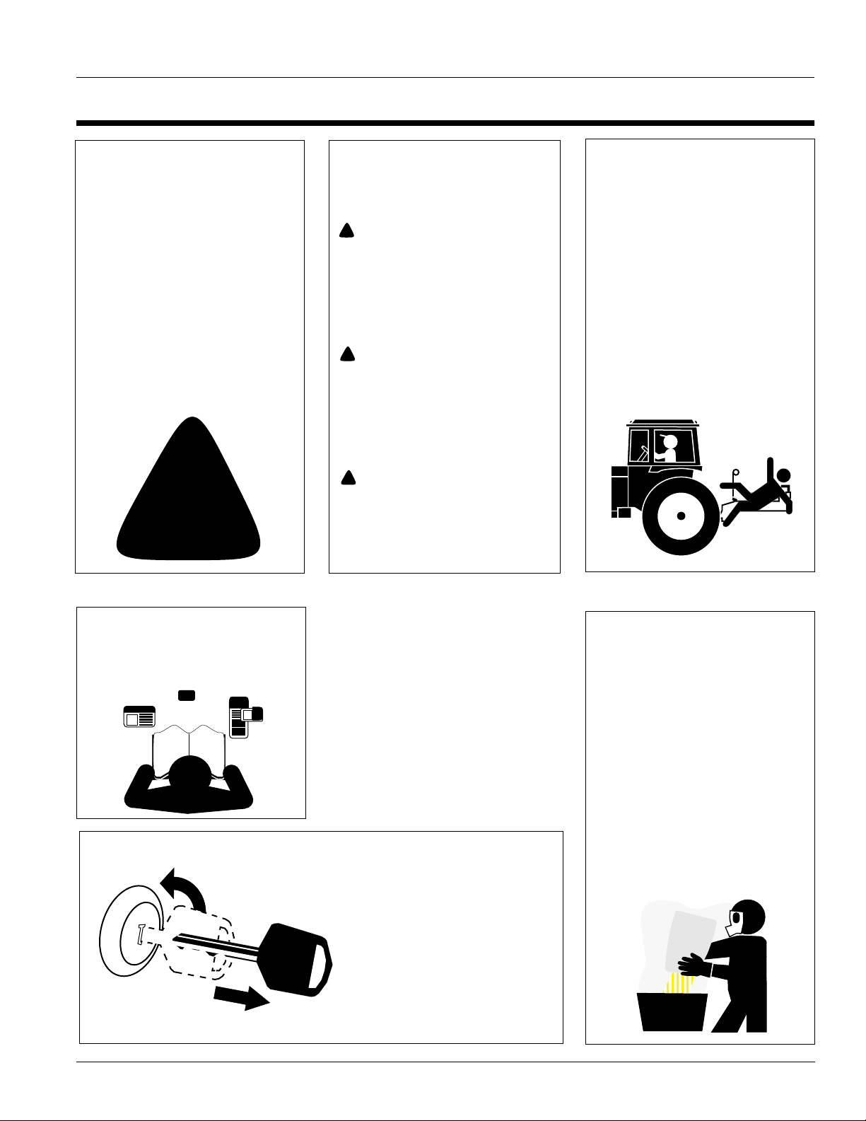
Look for Safety Symbol
The SAFETY ALERT SYMBOL indicates there is a potential hazard to
personal safety involved and extra
safety precaution must be taken.
When you see this symbol, be alert
and carefully read the message that
follows it. In addition to design and
configuration of equipment, hazard
control and accident prevention are
dependent upon the awareness, concern, prudence and proper training of
personnel involved in the operation,
transport, maintenance and storage
of equipment.
!
Be Aware of Signal Words
Signal words designate a degree or
level of hazard seriousness. The signal words are:
!
DANGER!
Indicates an imminently hazardous
situation which, if not avoided, will
result in death or serious injury. This
signal word is limited to the most
extreme situations, typically for
machine components that, for functional purposes, cannot be guarded.
!
WARNING!
Indicates a potentially hazardous situation which, if not avoided, could
result in death or serious injury, and
includes hazards that are exposed
when guards are removed. It may
also be used to alert against unsafe
practices.
!
CAUTION!
Indicates a potentially hazardous situation which, if not avoided, may
result in minor or moderate injury. It
may also be used to alert against
unsafe practices.
Keep Riders
Off Machinery
Riders obstruct the operator’s view.
Riders could be struck by foreign
objects or thrown from machine.
▲ Never allow riders on implement.
▲ Never allow children to operate
equipment.
For Your Protection
▲ Thoroughly read and understand
Safety Decals, page 4. Read all
instructions noted on decals.
OFF
Shutdown and Storage
▲ Lower machine to ground, put
tractor in park, turn off engine,
and remove key.
▲ Detach and store implement in an
area where children normally do
not play. Secure implement with
blocks and supports.
Handle
Chemicals Properly
Agricultural chemicals can be dangerous. Improper use can seriously
injure persons, animals, plants, soil
and property.
▲ Wear protective clothing.
▲ Handle all chemicals with care.
▲ Follow instructions on container
label.
▲ Avoid inhaling smoke from any
type of chemical fire.
▲ Store or dispose of unused chem-
icals as specified by chemical
manufacturer.
9/13/2006
NTA 2000D 148-632M
1
Page 4
Great Plains Mfg., Inc.
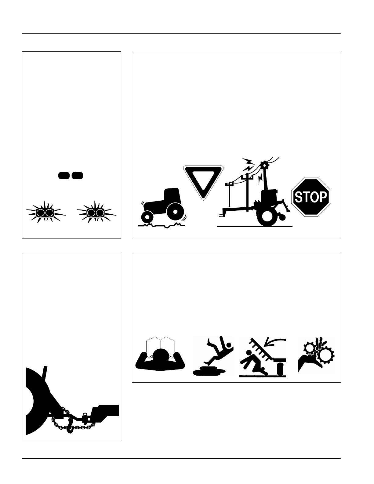
Use Safety
Lights and Devices
Slow-moving tractors, self-propelled
equipment and towed implements
can create a hazard when driven on
public roads. They are difficult to see,
especially at night.
▲ Use flashing warning lights and
turn signals whenever driving on
public roads.
▲ Use lights and devices provided
with implement.
Transport
Machinery Safely
Maximum transport speed for implement is 20 mph. Some rough terrains
require a slower speed. Sudden
braking can cause a towed load to
swerve and upset.
▲ Do not exceed 20 mph. Never
travel at a speed that does not
allow adequate control of steering
and stopping.
▲ Comply with state and local laws.
▲ Reduce speed if towed load is not
equipped with brakes.
▲ Do not tow an implement that,
when fully loaded, weighs more
than 1.5 times the weight of towing vehicle.
Use A Safety Chain
▲ Use a safety chain to help con-
trol drawn machinery should it
separate from tractor drawbar.
▲ Use a chain with a strength rat-
ing equal to or greater than
gross weight of towed machinery.
▲ Attach chain to tractor drawbar
support or other specified
anchor location. Allow only
enough slack in chain to permit
turning.
▲ Replace chain if any links or end
fittings are broken, stretched or
damaged.
▲ Do not use safety
chain for towing.
Practice Safe Maintenance
▲ Understand procedure before
doing work. Use proper tools and
equipment. Refer to this manual
for additional information.
▲ Work in a clean, dry area.
▲ Lower implement to ground, put
tractor in park, turn off engine,
and remove key before performing
maintenance.
▲ Allow implement to cool completely.
▲ Inspect all parts. Make sure parts
are in good condition and installed
properly.
▲ Remove buildup of grease, oil or
debris.
▲ Remove all tools and unused
parts from implement before operation.
NTA 2000D 148-632M 9/13/2006
2
Page 5
Great Plains Mfg., Inc.
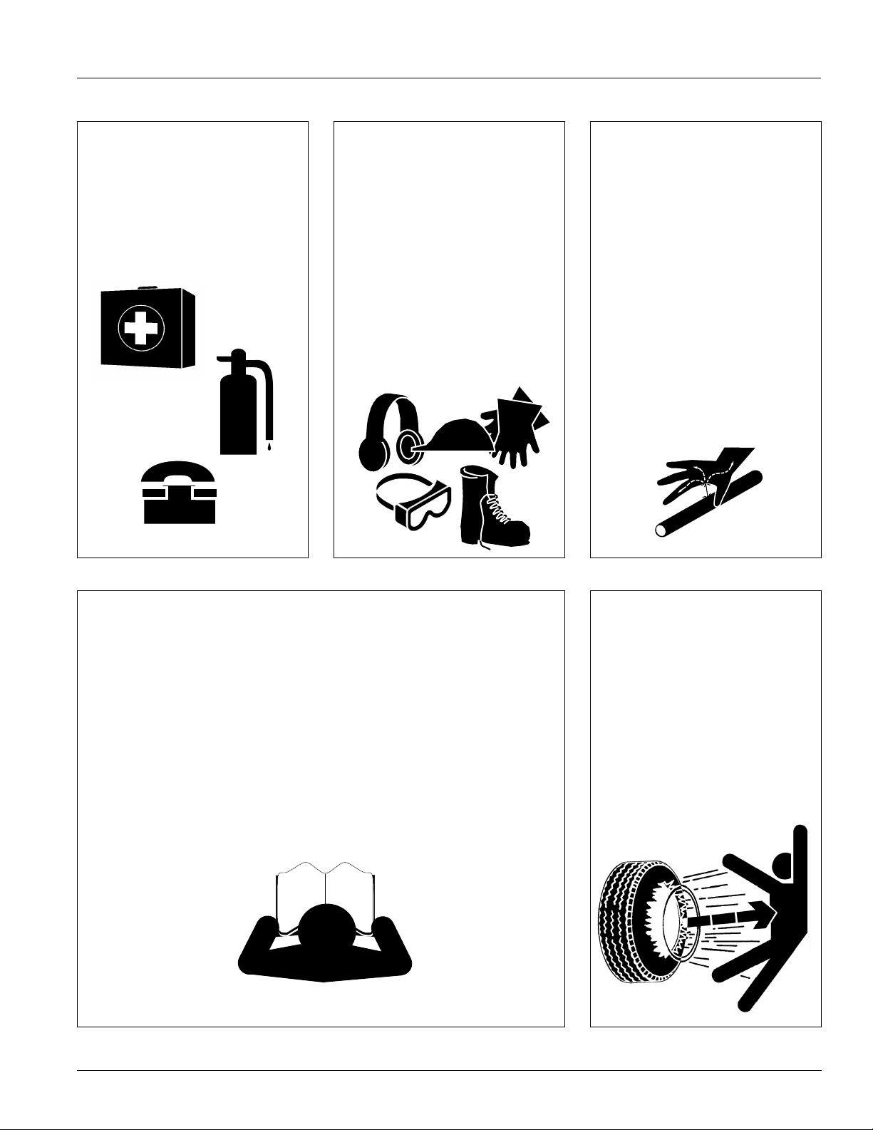
Prepare for Emergencies
▲ Be prepared if a fire starts.
▲ Keep a first-aid kit and fire extin-
guisher handy.
▲ Keep emergency numbers for
doctor, ambulance, hospital and
fire department near phone.
911
Wear
Protective Equipment
▲ Wear protective clothing and
equipment.
▲ Wear clothing and equipment
appropriate for the job. Avoid
loose-fitting clothing.
▲ Because prolonged exposure to
loud noise can cause hearing
impairment or hearing loss, wear
suitable hearing protection such
as earmuffs or earplugs.
▲ Because operating equipment
safely requires your full attention,
avoid wearing radio headphones
while operating machinery.
Avoid High
Pressure Fluids Hazard
Escaping fluid under pressure can
penetrate skin, causing serious
injury.
▲ Avoid the hazard by relieving
pressure before disconnecting
hydraulic lines.
▲ Use a piece of paper or card-
board, not body parts, to check for
suspected leaks.
▲ Wear protective gloves and safety
glasses or goggles when working
with hydraulic systems.
▲ If an accident occurs, see a doc-
tor immediately. Any fluid injected
into the skin must be surgically
removed within a few hours or
gangrene may result.
Safety at All Times
Thoroughly read and understand this
manual before operation. Refer to
Safety Decals, page 4. Read all
instructions noted on decals.
▲ Be familiar with all implement
functions.
▲ Operate implement from driver’s
seat only.
▲ Do not leave tractor or implement
unattended with engine running.
▲ Do not dismount a moving tractor.
Dismounting a moving tractor could
cause serious injury or death.
▲ Do not stand between tractor and
implement during hitching.
▲ Keep hands, feet and clothing
away from power-driven parts.
▲ Wear snug-fitting clothing to avoid
entanglement with moving parts.
▲ Watch out for wires, trees, etc.,
when raising implement. Make
sure all persons are clear of working area.
▲ Do not turn tractor too tight, caus-
ing implement to ride up on
wheels. This could result in injury
or equipment damage.
Tire Safety
Tire changing can be dangerous and
should be performed by trained personnel using correct tools and equipment.
▲ When inflating tires, use a clip-on
chuck and extension hose long
enough to allow you to stand to
one side–NOT in front of or over
the tire assembly. Use a safety
cage if available.
▲ When removing and installing
wheels, use wheel-handling
equipment adequate for weight
involved.
9/13/2006
NTA 2000D 148-632M
3
Page 6
Safety Decals
Your implement comes equipped with all safety decals in place.
They were designed to help you safely operate your implement.
1. Read and follow decal directions.
2. Keep all safety decals clean and legible.
3. Replace all damaged or missing decals. Order new decals
from your Great Plains dealer. Refer to this section for
proper decal placement.
Great Plains Mfg., Inc.
4. When ordering new parts or components, also request corresponding safety decals.
5. To install new decals:
a. Clean the area on which the decal is to be placed.
b. Peel backing from decal. Press firmly on surface,
being careful not to cause air bubbles under decal.
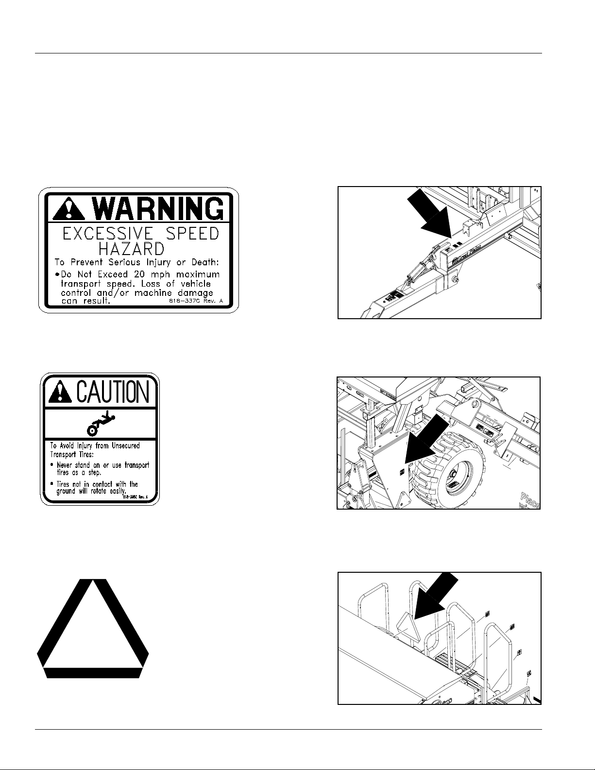
818-337C
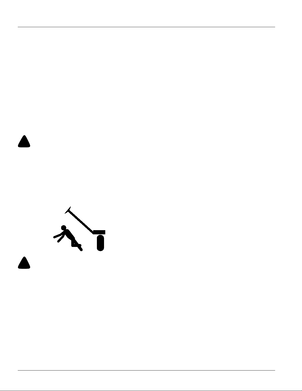
Excessive Speed Hazard
One decal on tongue.
818-398C
Not a Step
One decal on each side of main frame.
Two decals total.
19761
19761
818-003C
Slow Moving Vehicle
One decal on rear of box.
NTA 2000D 148-632M 9/13/2006
4
19761
Page 7
Great Plains Mfg., Inc.
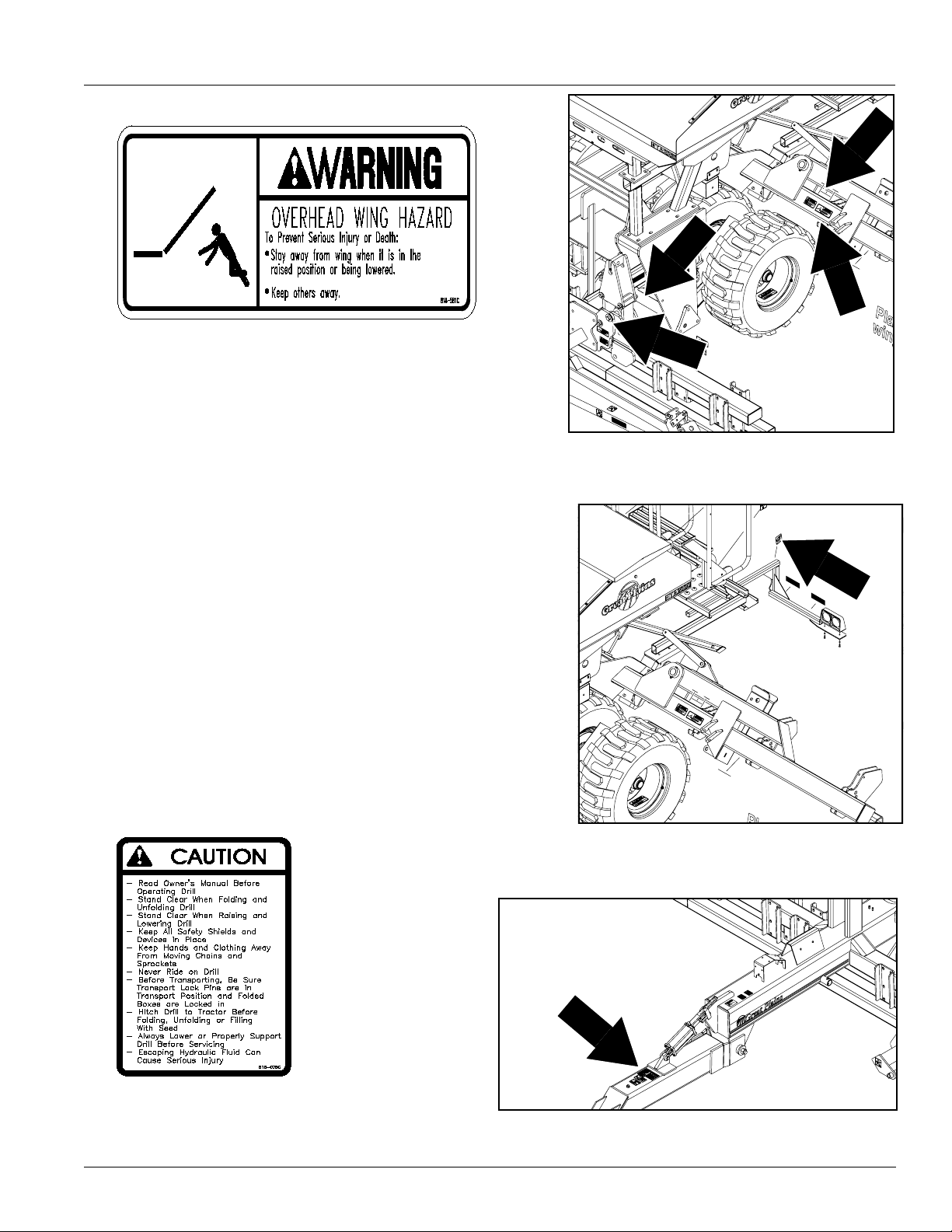
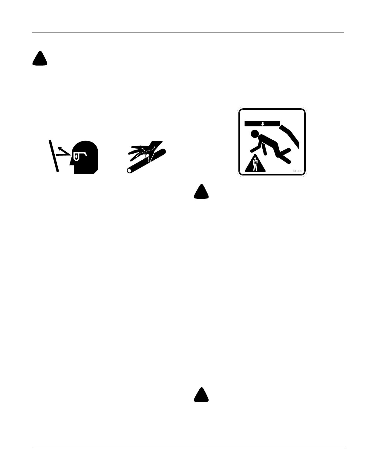
818-581C
Overhead Crushing
Two decals on each side of the opener frame hinges. Two
decals on each side of the coulter frame hinges. One decal
on light bar bracket near lower platform.
Nine decals total.
19761
818-078C
Read Manual
One decal on tongue.
9/13/2006
19761
NTA 2000D 148-632M
19761
5
Page 8
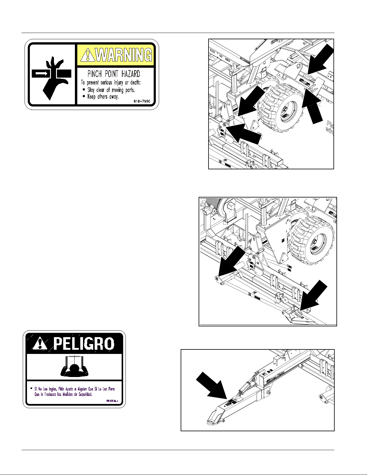
818-798C
Pinch Point
Two decals on each side of both opener frame hinges. Two
decals on each side of both coulter frame hinges. One decal
on each marker mount. One decal on top side of second
marker sections.
Twelve decals total.
Great Plains Mfg., Inc.
19761
818-557C
Cannot Read English
One decal on tongue.
NTA 2000D 148-632M 9/13/2006
6
19761
19761
Page 9
Great Plains Mfg., Inc.
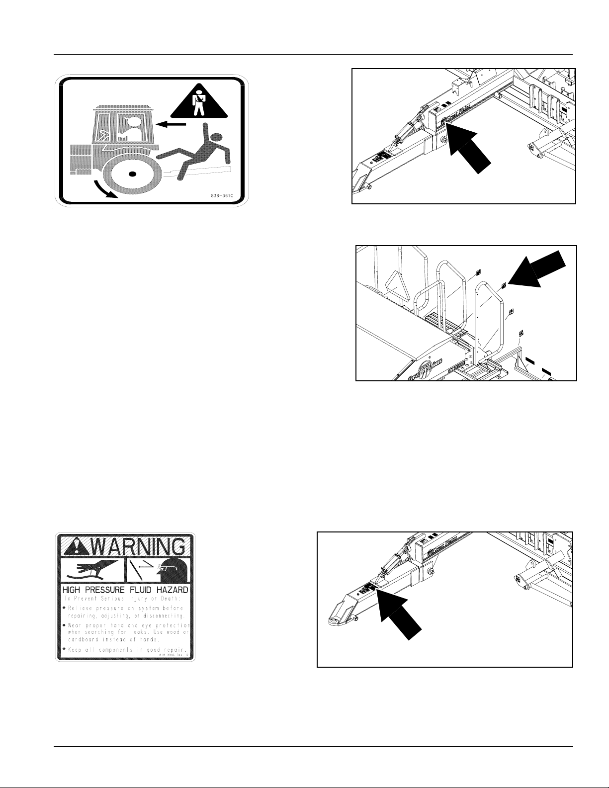
838-361C
Do Not Ride
One decal on tongue and one decal on the back of the upper
work platform.
Two decals total.
19761
818-339C
High Pressure Fluids
One decal on tongue.
.
19761
19761
9/13/2006
NTA 2000D 148-632M
7
Page 10
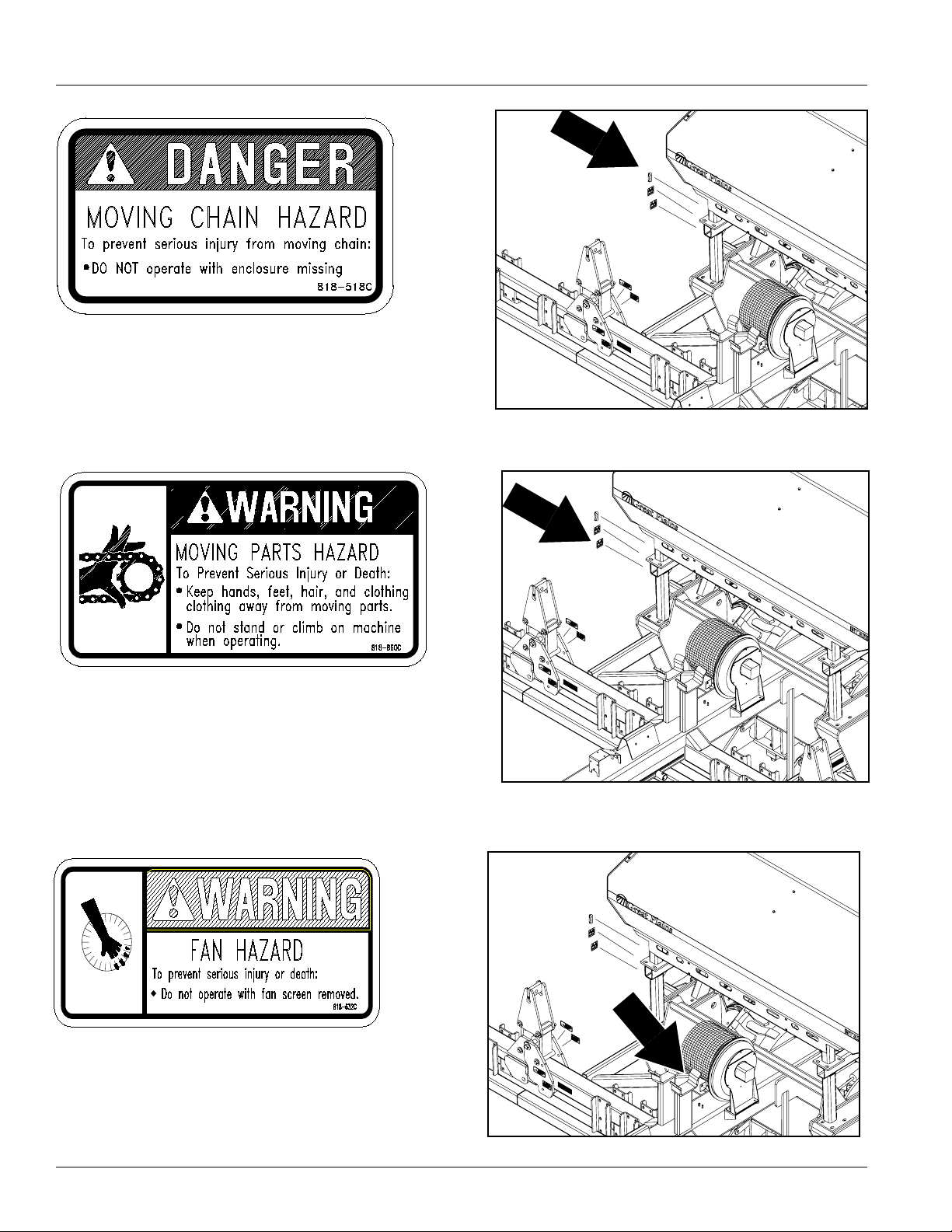
818-518C
Moving Chain Danger
One decal behind chain guard.
Great Plains Mfg., Inc.
19761
818-860C
Moving Chain
One decal on hopper frame near gearbox.
818-632C
Fan Hazard
One decal near fan.
19761
19761
NTA 2000D 148-632M 9/13/2006
8
Page 11
Great Plains Mfg., Inc.
838-265C
Amber Reflectors
One reflector under both opener wings. One reflector
on each side of coulter frame. Two on the front side of
coulter frame. One on the front side of each marker.
Eight reflectors total.
19761
838-266C
Red Reflectors
One reflector on outside ends of light mounting tubes.
Two reflectors total.
838-267C
Day Time Reflectors
One reflector on inside ends of light
mounting tubes.
Two decals total.
19761
19761
9/13/2006
NTA 2000D 148-632M
9
Page 12
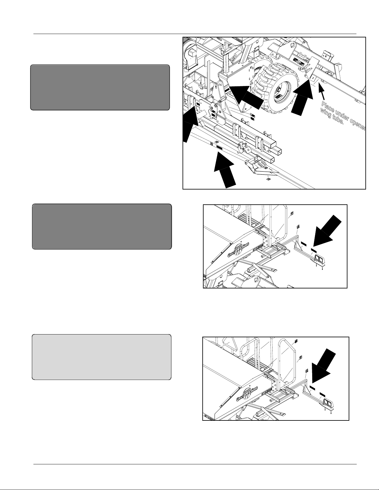
Great Plains Mfg., Inc.
818-590C
Crushing Hazard
One decal on tongue.
838-102C
Falling Hazard
One decal on upper platform.
19761
19761
818-682C
Crushing Hazard
One decal on underside first marker sections. One
decal on front side of first marker sections. One decal on underside of second marker sections.
Six decals total.
NTA 2000D 148-632M 9/13/2006
10
19761
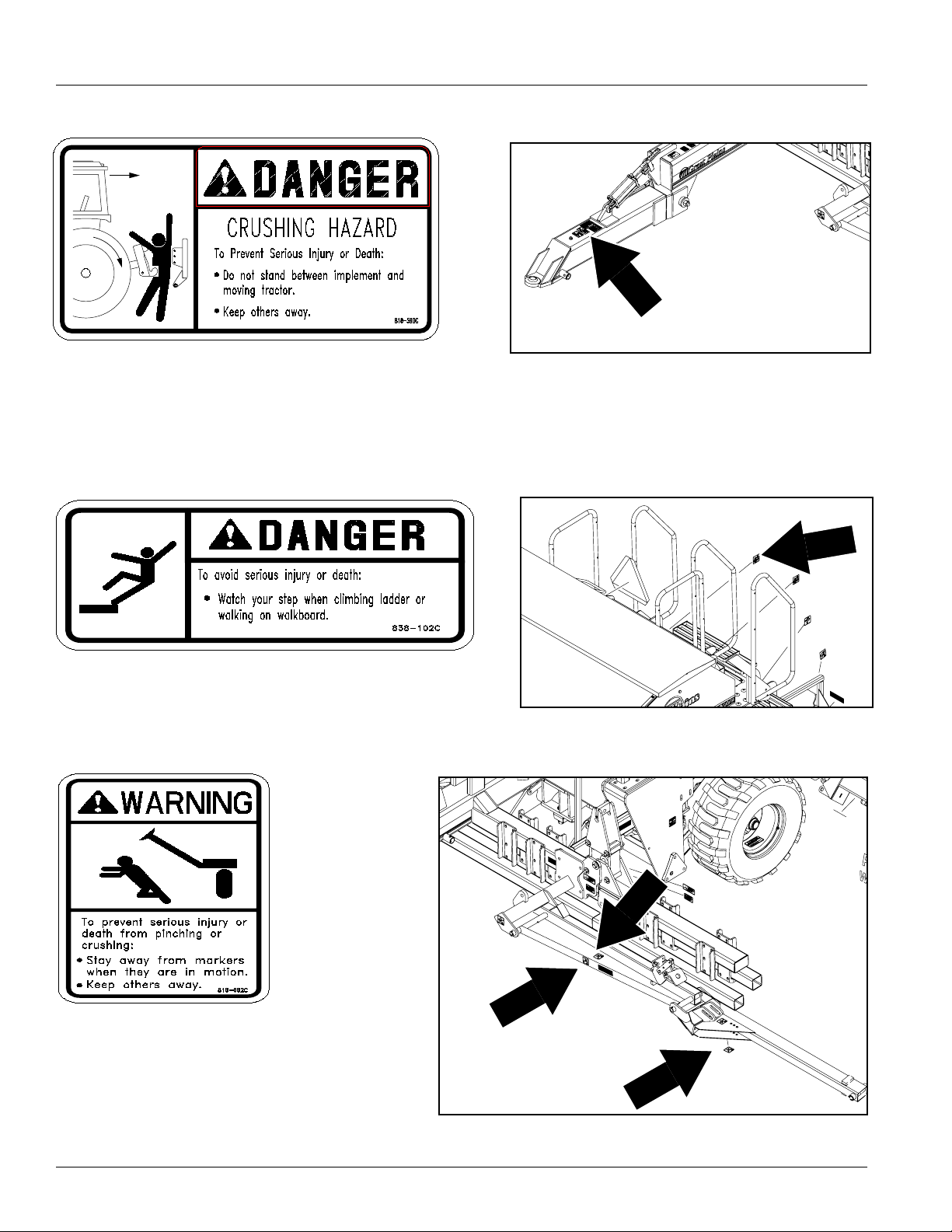
Page 13
Great Plains Mfg., Inc.
818-589C
Pinch Point Hazard
One decal on light bar near lower platform.
19761
838-426C
Tire Pressure
One decal on each tire rim.
Four decals total.
818-633C
Missing Guard Hazard
One decal on the auger hopper.
19761
9/13/2006
NTA 2000D 148-632M
11
Page 14

Introduction
Great Plains Mfg., Inc.
Great Plains welcomes you to its growing family of new
product owners. This implement has been designed with
care and built by skilled workers using quality materials.
Proper setup, maintenance and safe operating practices
will help you get years of satisfactory use from the
machine.
Description of Unit
The NTA 2000D is a pull-type seeding implement. The
implement has No-till coulters and openers intricately connected on a center pivot. No-till coulters mounted on the
front frame zone-till strips for seed furrows. Straight-arm
openers on the rear frame prepare seedbeds and place
the seed. The pivoting action of the frames allows drill
openers to track the coulters. A contact-drive tire powers
the seed meter from a transport tire. The tongue cylinder
and transport tires control the coulter and opener depth.
Transport cylinders raise the drill for turns and transport.
Intended Usage
Use this implement for seeding production-agriculture
crops only. Do not modify implement for use with attachments other than those specified by Great Plains. Use
implement in no till or minimum tillage.
Using This Manual
This manual will familiarize you with safety, assembly,
operation, adjustments, troubleshooting and maintenance. Read thismanual and follow the recommendations
to help ensure safe and efficient operation.
The information in this manual is current at printing. Some
parts may change to assure top performance.
Definitions
Right-hand and left-hand as used in this manual are determined by facing the direction the machine will travel while
in use unless otherwise stated.
IMPORTANT: A crucial point of information related to
the preceding topic. For safe and correct operation,
read and follow the directions provided before continuing.
NOTE: Useful information related to the preceding topic.
Owner Assistance
If you need customer service or repair parts, contact a
Great Plains dealer. They have trained personnel, repair
parts and equipment specially designed for Great Plains
products.
Your machine’s parts were specially designed and should
only be replaced with Great Plains parts. Always use
serial and model numbers when ordering parts from your
19731
Great Plains dealer. The serial-number plate is located on
the implement as shown in Figure A.
Figure A
Serial Number Plate
Record your implementmodel and serial numbers here for
quick reference:
Model Number: _________________________________
Serial Numbers: _________________________________
Your Great Plains dealer wants you to be satisfied with
your new machine. If you do not understand any part of
this manual or are not satisfied with the service received,
please take the following actions.
1. Discuss the matter with your dealership service manager. Make sure they are aware of any problems so
they can assist you.
2. If you are still not satisfied, seek out the owner or general manager of the dealership.
3. For further assistance write to:
Product Support
Great Plains Mfg. Inc., Service Department
PO Box 5060
Salina, KS 67402-5060
USA
NTA 2000D 148-632M 9/13/2006
12
Page 15
Great Plains Mfg., Inc.
Preparation and Set-Up
This section will help you prepare your tractor and implement for use.
Hitching Tractor to Implement
!
DANGER!
You may be severely injured or killed by being crushed between the tractor and drill. Do not stand or place any part of
your body between drill and moving tractor. Stop tractor engine and set park brake before installing pins.
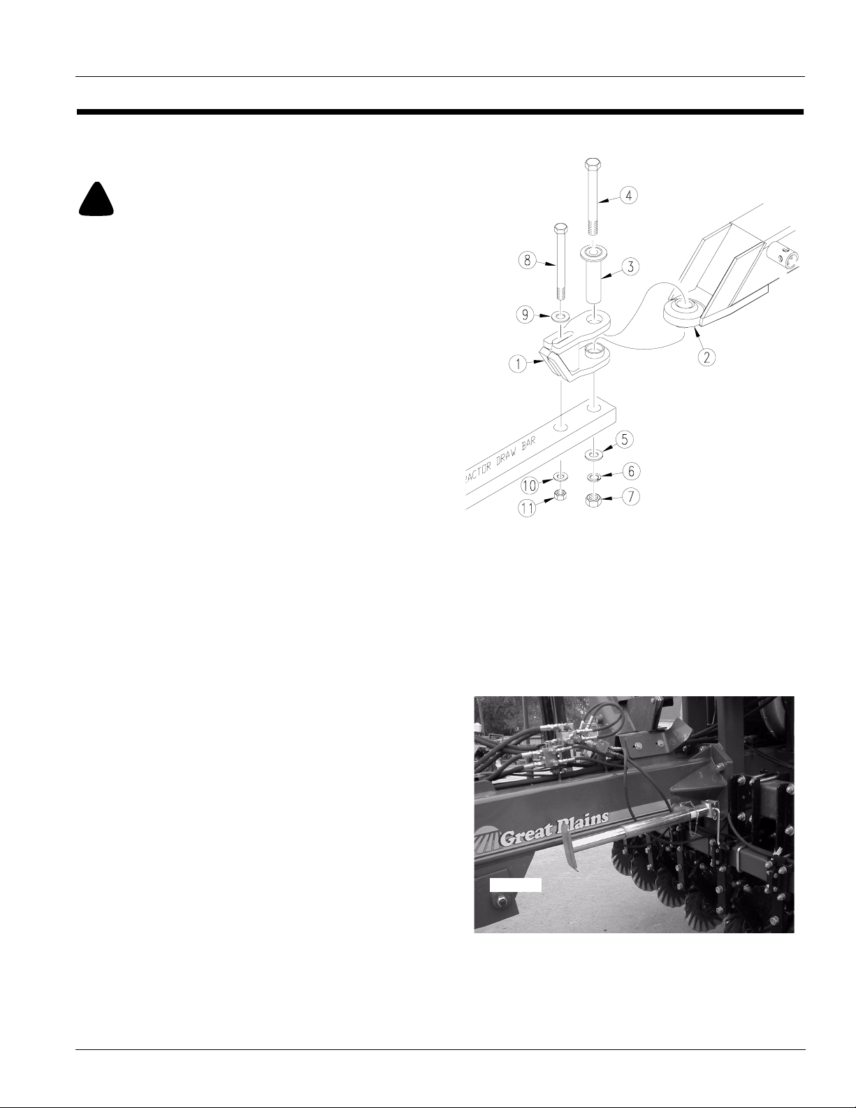
Refer to Figure 1
1. Place hitch weldment (1) over ball swivel on hitch
tongue (2). Hold hitch weldment in place by inserting
spacer tube (3) through hitch clevis and ball swivel.
2. Back tractor up to hitch and bolt hitch weldment to
tractor drawbar using 1” x 10" bolt (4), large flat
washer (5), lock washer (6), and nut (7).
3. Use 3/4” x 9" bolt (8) to bolt hitch weldment through
its slotted hole and onto secondary hole of tractor
drawbar. Install a 3/4” flat washer (9) next to top slotted hole and fasten with a lock washer (10) and nut
(11). Tighten both bolts.
4. Securely attach safety chain to tractor-drawbar
frame.
5. Plug light harness and monitor leads into tractor connections.
6. Connect hydraulic hoses to the tractor remotes.
Refer to Figure 2
7. Remove jack from stob on side of hitch tongue and
place in transport position on implement.
17215
Figure 1
Hitch
9/13/2006
19730
Figure 2
Jack in Transport
NTA 2000D 148-632M
13
Page 16
Hydraulic Hook-up
!
WARNING!
Escaping fluid under pressure can have sufficient force to penetrate the skin. Check all hydraulic lines and hoses before applying pressure. Fluid escaping from a very small hole can be
almost invisible. Use paper or cardboard, not body parts, to
check for suspected leaks. If injured, seek medical assistance
from a doctor that is familiar with this kind of injury. Foreign
fluids in the tissue must be surgically removed within a few
hours or gangrene will result.
Great Plains hydraulic hoses are color coded to help you
hook-up hoses to your tractor outlets. Hoses that go to the
same remote valve are marked with the same color.
Colour Hydraulic Function
Red Transport Lift Cylinders
Great Plains Mfg., Inc.
Blue Tongue Cylinder
Yellow Fan and Fold
Orange Marker
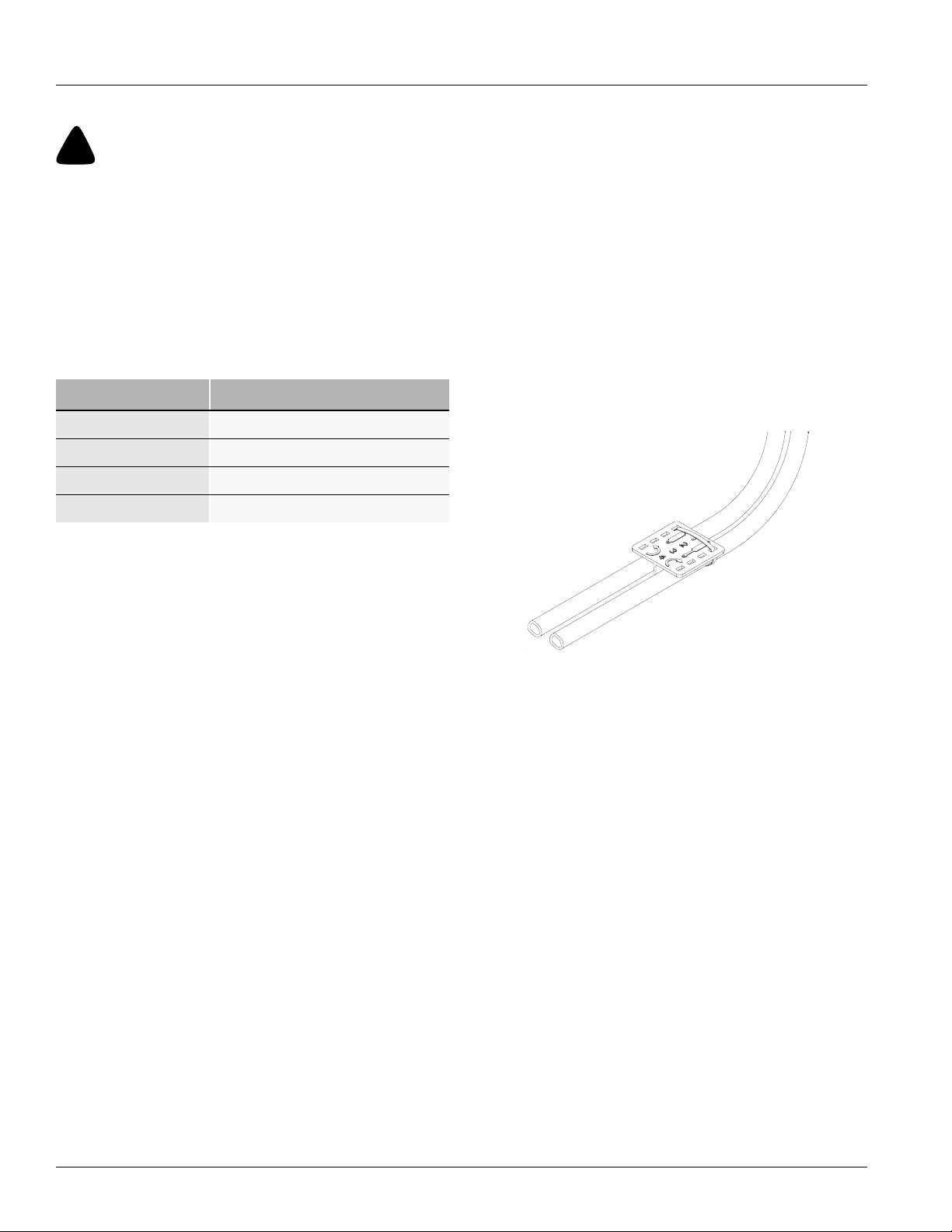
Refer to Figure 3
To distinguish hoses on the same hydraulic circuit, refer to
plastic hose holder. Connect hose under extended cylinder to outlet you choose for cylinder extension. Connect
hose under retracted symbol to outlet for cylinder
retraction.
Connect hydraulic hoses from tongue cylinder to one tractor remote valve. Connect hoses from transport-lift
cylinders to another tractor remote valve.
.
17641
Figure 3
Hydraulic Hose Color Ties
NTA 2000D 148-632M 9/13/2006
14
Page 17
Great Plains Mfg., Inc.
Bleeding Hydraulic Systems
!
WARNING!
Escaping fluid under pressure can have sufficient pressure to
penetrate the skin. Check all hydraulic lines and fittings before
applying pressure. Fluid escaping from a very small hole can be
almost invisible. Use paper or cardboard, not body parts, and
wear heavy gloves to check for suspected leaks. If injured, seek
medical assistance from a doctor that is familiar with this type
of injury. Foreign fluids in the tissue must be surgically removed
within a few hours or gangrene will result.
Note: For safe and smooth operation, the hydraulic systems must be free of air. The hydraulic systems should be
bled during initial implement set-up. If they were not bled,
or if you replace a hydraulic component during the life of
the drill, bleed the hydraulics.
Bleeding Lift Hydraulics
1. Check hydraulic fluid level in tractorreservoir and fill to
proper level. Add fluid to system as needed while cycling new cylinders. LIft hydraulic capacity is 2 gallons
(7.5 liters).
2. Lower drill to ground.
3. Loosen the fittings at the base end of each transport
lift cylinder. Supply oil to the base ends of the cylinders until oil seeps from loosened fittings. Tighten
those fittings.
4. Supply oil to the base ends and completely extend the
cylinders. Insert transport lock channels.
5. Loosen the fittings at the rod end of each transport lift
cylinder. Supply oil to the rod ends of the cylinders until oil seeps from loosened fittings. Tighten those fittings.
6. Remove transport lock channels and cycle drill up and
down three times.
Bleeding Tongue Cylinder
1. Check hydraulic fluid in tractor reservoir and fill to
proper level. Add fluid to system as needed. Tongue
cylinder capacity is 1/2 gallon (1.9 litres).
2. Raise and safely support hitch, transport frame and
front tongue.
3. Unpin rod end of tongue cylinder. Block, wire or other-
wise safely support cylinder so when rod end is fully
extended it does not contact anything.
4. Cycle cylinder completely in and out at least three
times to purge air from cylinder and hoses.
5. Fully extend cylinder and repin rod end.
6. Recheck tractor reservoir and fill to proper level.
!
CAUTION!
You may be injured or killed by a folding or unfolding opener or
coulter frame.
Bleeding Fold Hydraulics
Check hydraulic fluid level in tractor reservoir and fill to
proper level. Add fluid to system as needed while cycling
new cylinders. Fold hydraulic capacity is 2 gallons (7.5
liters).
If drill is folded:
1. Make sure the opener fold lock pins are in place. Loosen the fittings at the rod end of each coulter fold cylinder and at the base end of each opener fold cylinder.
Supply oil as to unfold the drill. As oil begins to seep
from the loosened fittings, tighten those fittings. Do
not unfold the wing sections at this time.
2. Make sure the opener fold lock pins are in place. Loosen the fittings at the base end of each coulter fold cylinder and at the rod end of each opener fold cylinder.
Supply oil as to fold the drill. As oil begins to seep from
the loosened fittings, tighten those fittings. Continue
supplying oil as to completely fold the drill for at least
five seconds.
3. Remove the fold lock pins and unfold the drill.
!
CAUTION!
Use extreme caution because some sudden dropping of the
wings may occur if a small amount of air still remained in the
cylinders.
4. Fold and unfold the drill three more times.
9/13/2006
NTA 2000D 148-632M
15
Page 18
If drill is unfolded:
1. Make sure the wing sections are on the ground. Loosen the fittings at the base end of each coulter fold cylinder and at the rod end of each opener fold cylinder.
Supply oil as to fold the drill. As oil begins to seep from
the loosened fittings, tighten those fittings. Do not fold
the wing sections yet.
2. Make sure the wing sections are still on the ground.
Loosen the fittings at the rod end of each coulter fold
cylinder and at the base end of each opener fold cylinder. Supply oil as to unfold the drill. As oil begins to
seep from the loosened fittings, tighten those fittings.
Continue supplying oil as to completely unfold the drill
for at least five seconds.
3. Fold the drill.
!
CAUTION!
Use extreme caution because some sudden dropping of the
wings may occur if a small amount of air still remained in the
cylinders.
Great Plains Mfg., Inc.
2. With tractor idling, activate tractor hydraulic valve until
oil seeps out around a loosened fitting. Tighten that fitting.
IMPORTANT: JIC fittings do not require high torque. JIC
and O-ring fittings do not require sealant. Always use liquid pipe sealant when adding or replacing pipe-thread fittings. To avoid cracking hydraulic fittings from over
tightening, do not use plastic sealant tape.
3. Reactivate tractor hydraulic valve until oil seeps out
around another loosened fitting. Tighten that fitting.
Repeat process until all loosened fittings have been
bled and tightened.
4. Cycle both cylinders completely in and out at least
three times to completely purge air from cylinders and
hoses.
5. Repin cylinders and cycle markers at least three
times.
4. Fold and unfold the drill three more times.
Bleeding Marker Hydraulics
To fold properly, the marker hydraulics must be free of air.
If the markers fold in jerky, uneven motion, follow these
steps.
!
CAUTION!
You may be injured if hit by a folding or unfolding marker.
Markers may fallquickly and unexpectedly if the hydraulics fail.
Never allow anyone near the drill when folding or unfolding the
markers.
Check that tractor hydraulic reservoir is full. Marker hydraulic capacity is 1 1/2 gallons (5.8 liters).
1. With both markers lowered into field position, unpin
rod end of each cylinder andblock cylinder up so it can
be extended and retracted safely and without contacting anything. Loosen hydraulic-hose fittings at rod and
base ends of marker cylinders. Loosen fittings on
back side of sequence valve.
IMPORTANT: Never bleed an O-ring fitting. Instead,
bleed a nearby pipe or JIC fitting.
NTA 2000D 148-632M 9/13/2006
16
Page 19
Great Plains Mfg., Inc.
Operating Instructions
This section covers general operation. Experience,
machine familiarity, and the following information will lead
to efficient operation and good working habits. Always
operate farm machinery with safety in mind.
Prestart Checklist
1. Carefully read “Important Safety Information,” be-
ginning on page 1.
2. Lubricate implement as indicated under Lubrication,
“Maintenance and Lubrication,” page 42.
3. Check all tires for proper inflation as indicated on Tire
Inflation Chart,“Appendix,” page 53.
4. Check all bolts, pins and fasteners. Torque as speci-
fied on Torque Values Chart,“Appendix,” page 53.
5. Check implement for worn or damaged parts. Repair
or replace before going to the field.
6. Check hydraulic hoses, fittings and cylinders for leaks.
Repair or replace before going to the field.
Field Operation
1. Hitch implement to a suitable tractor. Refer to Hitching
Tractor to Implement,“Preparation and Setup,” page
13.
2. Set seeding rate. Refer to “Checking the Seeding
Rate,” page 36.
3. Load box with clean seed.
4. Lower the drill and hydraulically adjust coulters to de-
sired depth. Note reference measurement on tonguecylinder gauge to help you achieve the same coulter
depth with each field pass. Refer to Coulter Depth,
“Adjustments,” page 27, for further adjustment instructions.
5. Retract transport cylinders until opener bodies are
level with the ground when the coulters are at the desired depth. Cylinder depth rings are provided to hold
the openers to the desired setting. Set opener depth
and begin seeding. Refer to Opener Depth,“Adjust-
ments,” page 30.
6. Always lift drill out of ground when turning at row ends
and for other sharp turns. Seeding will stop automatically as drill is raised and contact drive wheels lose
contact with drive tires.
9/13/2006
NTA 2000D 148-632M
17
Page 20
Opener Operation
Never back up with openers in ground. If you do, check all
openers to be sure none are clogged or damaged.
For information on seeding depth and opener adjustments, refer to Seeding Depth,“Adjustments,” page 26.
For more information on troubleshooting opener problems, see “Troubleshooting,” page 39.
Fan Operation
Refer to Figure 4
The selector valve diverts the folding circuit to the fan
circuit.
The fan must be operated with the return oil line connected to a low back pressure sump return on the tractor.
Check with tractor manufacturer for proper connection of
oil sump return line. A low back pressure quick disconnect
is supplied with the drill for ease of connection to the tractor sump return line.
Use tractor remote hydraulic valve flow control to set fan
speed.
Run fan for at least 15 minutes before seeding. Hydraulic
fluid must be warm before fan will operate properly.
Watch monitor and adjust fan speed by increasing or
decreasing hydraulic flow from tractor.
Use the fan speed chart as a guide. Actual fan speeds will
vary with seeding rates, seed weights and seed size.
Increase fan speed for heavier seeding rate or seed.
Reduce fan speed for lighter seeding rates and seed more
prone to cracking.
Set the fan speed for the type of seed and seed rate being
planted. Refer to “Seed Rate Charts,” page 48. Operating
the fan at higher than recommended speeds can cause
seeds to be blown out of the opener seed trench.
Note: Do not operate fan above 4500 RPM.
Fan
Figure 4
Turn Selector Valve
Great Plains Mfg., Inc.
19879
Follow the chart at the right as a guide. Actual fan speeds
will vary with seeding rates, seed weights and seed size.
Increase fan speed for heavier seeding rates or seed.
Reduce fan speed for lighter seeding rates and seed more
prone to cracking.
Marker Operation
Optional markers are on their own hydraulic circuit. They
operate through a sequence valve which alternates lower
and lift cycles between the right hand and left hand
marker.
NTA 2000D 148-632M 9/13/2006
18
Fan Speed Chart
Seeds Fan RMP
Sunflowers 2250-3000
Wheat 2800-3200
Soybeans 2750-3500
Milo 2250-3000
Barley 2800-3500
Peas 3200-3500
Canola 2000-2200
Grass 2000-2200
Page 21
Great Plains Mfg., Inc.
Folding the Drill
Fold the drill on level ground. Be aware of clearance
required to fold implement. Refer to “Specifications and
Capacities,” page 47.
!
WARNING!
Pinch Point and Crushing Hazard. To prevent serious injury or
death. Be certain the drill is hitched securely to your tractor
drawbar and the hitch safety chain is securely attached to the
tractor before raising or folding the drill.
• Always lift drill when before folding.
• Fold only if hydraulics are bled free of air and fully charged
with hydraulic oil.
• Keepaway and keep others away when folding or unfolding
drill.
Note: Fold the drill on level ground with the tractor in neutral.
Figure 5
Lock Guard Installed
19733
1. Hydraulically lift drill with transport-lift cylinders and
tongue cylinder.
Refer to Figure 5
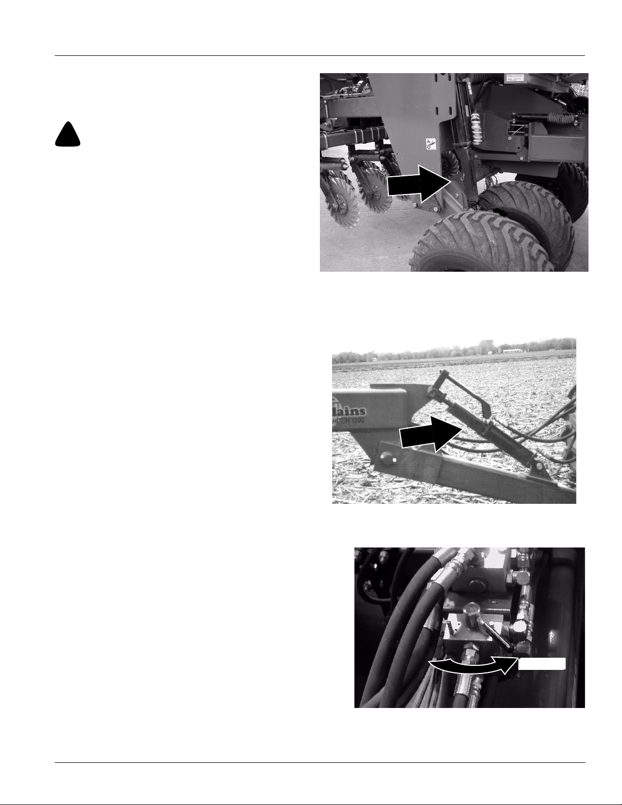
2. Install transport lock channels on the extended gauge
wheel cylinder rods.
Refer to Figure 6
3. Install lock channel over extended tongue-cylinder
rod.
Refer to Figure 7
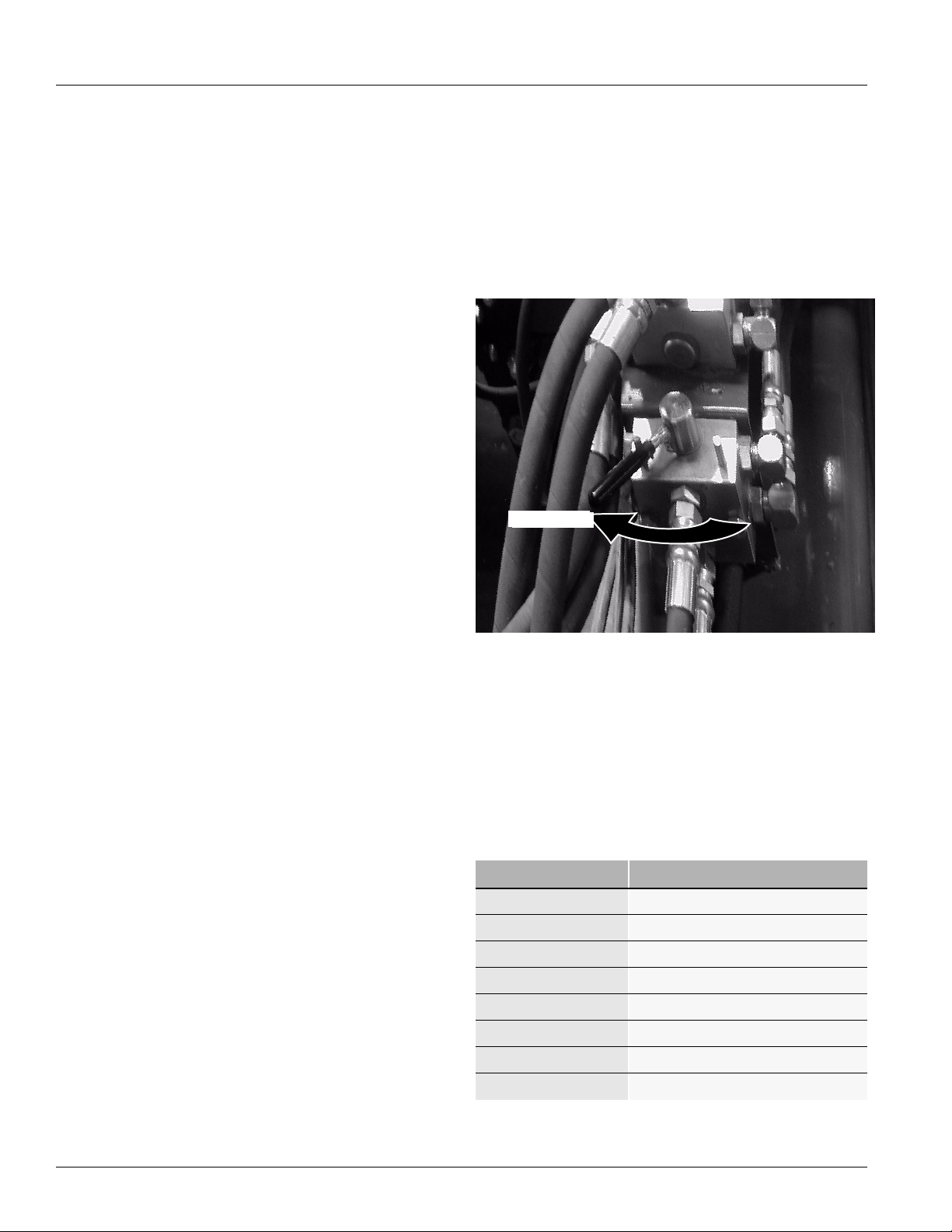
4. Turn handle counterclockwise on valve to folding posi-
tion.
Figure 6
Lock Channel Installed
17217
9/13/2006
Figure 7
Valve
NTA 2000D 148-632M
Folding
19732
19
Page 22
Folding the Drill
!
WARNING!
Pinch Point and Crushing Hazard. To prevent serious injury or
death. Be certain the drill is hitched securely to your tractor
drawbar and the hitch safety chain is securely attached to the
tractor before raising or folding the drill.
• Always lift drill when before folding.
• Fold only if hydraulics are bled free of air and fully charged
with hydraulic oil.
Great Plains Mfg., Inc.
• Keepaway and keep others away when folding or unfolding
drill.
Markers
Note: If maker option is installed, markers must be folded
before coulter wings can be folded.
Refer to Figure 8
5. Before folding markers remove cylinder lock channels
from cylinders and place in storage positions. Failure
to do so will not allow the markers to travel to their
transport positions.
Refer to Figure 9
6. Fold markers to their transport positions. The second
marker section should rest on top of drill frame main
tube.
:
Figure 8
Marker Cylinder Lock Channel
Figure 9
Marker, Transport Position
19894
19877
Opener Wing Frame
Refer to Figure 10
7. Turn opener wing frame lock handles down to unlock
opener wing frames.
Figure 10
Opener Wing Frame Lock
NTA 2000D 148-632M 9/13/2006
20
19734
Page 23
Great Plains Mfg., Inc.
Folding the Drill
!
WARNING!
Pinch Point and Crushing Hazard. To prevent serious injury or
death. Be certain the drill is hitched securely to your tractor
drawbar and the hitch safety chain is securely attached to the
tractor before raising or folding the drill.
• Always lift drill when before folding.
• Fold only if hydraulics are bled free of air and fully charged
with hydraulic oil.
• Keepaway and keep others away when folding or unfolding
drill.
Coulter Wing Frame
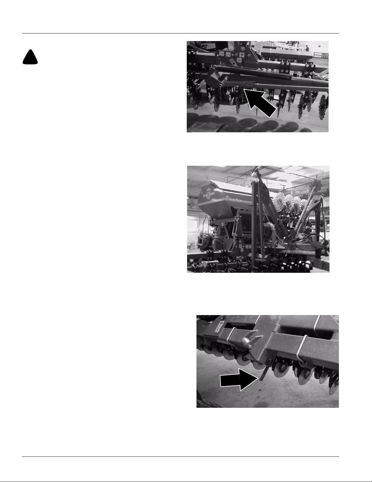
Refer to Figure 11
8. Remove lock pins from lock links
Figure 11
Coulter Extension
19736
Refer to Figure 12
9. Store lock pins in storage hole as shown. Flip up lock
links to keep the drill transport width below 118” (3
meters).
10. Allow tongue and transport cylinders to settle back
against the lock channels.
!
DANGER!
Electrocution hazard. To prevent serious injury or death from
electric shock, keep clear of overhead power lines when transporting, folding, unfolding or operating all air-drill components. Machine is not grounded. Electrocution can occur
without direct contact.
11. Fold opener and coulter wings.
Refer to Figure 13
12. Install opener wing frame lock pin to keep opener wing
frames secure in their transport position.
Figure 12
Lock Link Pin Storage
19738
9/13/2006
Figure 13
Opener Wing Frame Lock Pin
NTA 2000D 148-632M
19736
21
Page 24
Unfolding the Drill
Unfold the drill on level ground. Be aware of clearance
required to fold implement. Refer to “Specifications and
Capacities,” page 47.
!
WARNING!
Pinch Point and Crushing Hazard. To prevent serious injury or
death. Be certain the drill is hitched securely to your tractor
drawbar and the hitch safety chain is securely attached to the
tractor before raising or unfolding the drill.
Great Plains Mfg., Inc.
• Unfold the wings with the drill raised.
• Fold only if hydraulics are bled free of air and fully charged
with hydraulic oil.
• Keepaway and keep others away when folding or unfolding
drill
Opener Extensions.
Refer to Figure 14
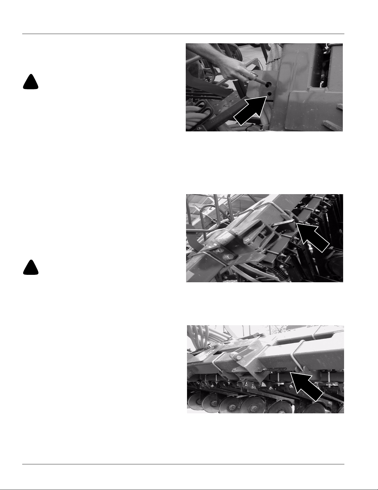
1. Remove transport lock pins from opener wings and
place in storage holes indicated by arrow.
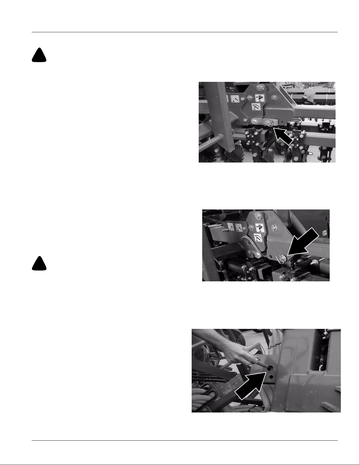
Refer to Figure 15
2. Make sure the lock levers are in the unlock position.
The levers should be in a position which is pointing
away from the frame.
3. Unfold the drill on level ground with the tractor in neutral.
!
DANGER!
Electrocution hazard. To prevent serious injury or death from
electric shock, keep clear of overhead power lines when transporting, folding, unfolding or operating all air-drill components. Machine is not grounded. Electrocution can occur
without direct contact.
Figure 14
Lock Pin
Figure 15
Lock Lever
19736
19740
Refer to Figure 16
4. When opener wings are in their lowered position lock
in place by engaging thelock levers. The levers should
be pushed towards the frame to lock.
Figure 16
Lock Lever
NTA 2000D 148-632M 9/13/2006
22
19741
Page 25

Great Plains Mfg., Inc.
Unfolding the Drill
!
WARNING!
Pinch Point and Crushing Hazard. To prevent serious injury or
death. Be certain the drill is hitched securely to your tractor
drawbar and the hitch safety chain is securely attached to the
tractor before raising or unfolding the drill.
• Unfold the wings with the drill raised.
• Fold only if hydraulics are bled free of air and fully charged
with hydraulic oil.
• Keepaway and keep others away when folding or unfolding
drill
Coulter Extensions
Refer to Figure 17
5. After unfolding the coulter wing extensions, secure in
place with lock links and lock pins.
Makers
Note: For drills with maker option installed.
Refer to Figure 18
6. After the drill has been unfolded lower the makers and
install the lock channels over the cylinder rod as
shown. This allows the maker cylinders to retract for
field operation without retracting all the way to transport position.
Figure 17
Lock Link and Pin
Figure 18
Lock Channel
19743
19744
9/13/2006
NTA 2000D 148-632M
23
Page 26

Unfolding the Drill
!
WARNING!
Pinch Point and Crushing Hazard. To prevent serious injury or
death. Be certain the drill is hitched securely to your tractor
drawbar and the hitch safety chain is securely attached to the
tractor before raising or unfolding the drill.
• Unfold the wings with the drill raised.
• Fold only if hydraulics are bled free of air and fully charged
with hydraulic oil.
• Keepaway and keep others away when folding or unfolding
drill
Refer to Figure 19 and 20
1. After the drill has been unfolded remove the lock
channels from the tongue cylinder and the gauge
wheel cylinders. Slowly lower drill and place lock
channels in their storage positions.
Figure 19
Lock Channel
Great Plains Mfg., Inc.
19878
Refer to Figure 21
2. Turn selector valve handle to the left for fan position.
Fan
Figure 20
Lock Channel
Figure 21
Valve
19733
19732
NTA 2000D 148-632M 9/13/2006
24
Page 27

Great Plains Mfg., Inc.
Transporting
!
WARNING!
Towing the implement at high speeds or with a vehicle that is
not heavy enough can lead to loss of vehicle control. Loss of vehicle control can lead to serious road accidents, injury and
death. To reduce the hazard:
• Do not exceed 20 mph (25kph).
• Do not tow an implement that, when fully loaded, weighs
more than 1.5 times the weight of the towing vehicle.
1. Check that implement is securely hitched to a suffi-
cient tractor. Refer to Hitching Tractor to Implement,
“Preparation and Setup,” Page 13. Make sure safety
chain is secured to tractor.
2. Unload seed box before transporting if at all possible.
The implement can be transported with a full box of
grain, but added weight will increase stopping distance and decrease maneuverability.
3. Check that tires are properly inflated. Refer to Tire In-
flation Chart,“Appendix,” page 53.
4. Know implement dimensions in transport position.
Choose a route that provides adequate clearance
from all obstructions. Refer to “Specifications and
Capacities,” page 47, for dimensions.
5. Plug light-harness lead into tractor connector. Always
use warning lights when transporting drill.
Comply with all laws when travelling on public roads.
Parking
Perform the following steps when parking implement.
Refer to Storage ,“Maintenance and Lubrication,” page
41, for information on long-term storage preparation.
6. Raise and install cylinder locks
7. Fold and lock wings.
8. Block tires securely to prevent rolling.
9. Release pressure on hydraulic system, then discon-
nect hydraulic lines. Check that hose ends do not rest
on ground.
Refer to Figure 22
10. Move jack from transport position and place it on stob
on side of hitch tongue.
11. Extend jack until all weight is off tractor drawbar. Re-
move 1” x 10” bolt and 3/4” x 3” drawbar bolt.
12. Disconnect implement light harness, monitor and
power cord.
Figure 22
Tongue Jack
19752
9/13/2006
NTA 2000D 148-632M
25
Page 28

Adjustments
Seeding Depth
To set drill seeding depth, you must:
• Set coulter depth with tongue cylinder and gauge
wheels.
• Set opener depth with T-handles on press wheel.
• If field conditions make it necessary, increase coulter
down pressure by adding tractor weights to frame. Refer to Added Weight, page 29.
• If necessary, adjust individual coulters or openers to
seed in tire tracks.
The following is an introduction to how the coulters and
double-disk openers are designed to control seeding
depth.
Coulters
A no-till coulter is mounted on the coulter frame directly
ahead of each opener on the drill. The coulters cut through
heavy trash and make a tilled path in the soil for the
openers.
Coulter cutting depth is controlled by the tongue cylinder
and the gauge wheels. You also can change the depth of
individual coulters by changing coulter-mounting height.
Refer to Coulter Depth, page 27, for information on these
adjustments.
The amount of coulter down pressure needed to cut a soil
groove varies with soil conditions. Adding weight or shortening the coulter spring increases coulter down pressure
and cutting force. Refer to Coulter Down Pressure, page
29, for more information on these adjustments.
Openers
Opener double disks travel in the coulter path to make a
seed bed. Mounted on the rear of each opener is a press
wheel. The press wheels control opener seeding depth
and firms the seed into the soil.
To maintain a consistent seeding depth, upward press
wheel movement is restricted by an independently adjustable stop on each opener. Moving this stop changes the
depth at which seed is placed. The mounting height of
openers that run in tire tracks also can be changed. Refer
to Opener Depth, page 30, for information on these
adjustments.
The amount of opener down pressure needed to cut and
widen the coulter groove and to firm the seed into the soil
varies with soil conditions. Opener down pressure can be
adjusted for all openers or individual openers. Refer to
Opener Down Pressure, page 31, for information on how
to make these adjustments.
Great Plains Mfg., Inc.
NTA 2000D 148-632M 9/13/2006
26
Page 29

Great Plains Mfg., Inc.
Coulter Depth
Adjust coulters to run 1/2” to 1” (13 to 25 mm) below the
drill openers. Coulter depth can be adjusted hydraulically
for all coulters or manually for individual coulters.
Hydraulic Control
Make the following adjustment when drilling in level
ground with the seed box half full.
1. Retract tongue cylinder to transfer the tractor weight to
the coulter toolbar.
17218
Refer to Figure 23
2. Lower the drill and set tongue cylinder so coulters are
at desired depth. Note the setting on cylinder gauge
so you can return to the same depth.
NOTE: Use cylinder gauge only as a reference. Gauge
does not measure actual coulter depth.
Refer to Figure 24
3. Adjust the cylinder spacers on the transport cylinders
so the opener bodies are level with the ground when
the coulters and openers are at the desired depth.
Figure 23
Cylinder Gauge
Figure 24
Spacers
19750
Refer to Figure 25
4. The bottom of the 3 x 3 opener frame tube should be
16 1/2” to 18 1/4” off the ground with the opener at the
desired depth and the opener bodies level with the
ground.
9/13/2006
Levelling Implement
Figure 25
Opener Depth
NTA 2000D 148-632M
19885
12961
27
Page 30

Coulter Wing Adjustment
Set the coulter wing frames so the wing coulters run at
exactly the same depth as the center frame coulters. This
is accomplished with two adjustments.
Refer to Figure 26
1. Add or remove spacer shims from behind coulter
frame stop studs. The studs should allow the coulters
to drop slightly below the desired operating depth to
allow the coulter lock pins to be installed and removed
easily.
Great Plains Mfg., Inc.
Refer to Figure 27
2. Adjust the lock link trunnion nuts so the wing coulters
run exactly the same depth as the center frame coulters. The coulters must be lowered into the ground so
soil pressure is forcing the wings upward to make sure
the lock link trunnions are properly set.
Figure 26
Stop Stud Spacers
19882
Figure 27
Lock Link Trunnion
19883
Note: This view is looking straight up from beneath
the coulter wing hinge.
NTA 2000D 148-632M 9/13/2006
28
Page 31

Great Plains Mfg., Inc.
Coulter Mounting Height
You can change the depth of individual coulters by adjusting coulter-mounting height. If you adjust coulter height,
be sure to rebolt coulters vertically straight and correctly
spaced. To raise or lower individual coulters:
1. Loosen mounting clamps and adjust coulterto desired
height. Do not lower coulter spring bar below top Ubolts on coulter clamp.
Refer to Figure 28
2. To re-tighten clamps. Snug hex-head clamp bolts (1)
just until U-bolts are tight on each side of spring bar.
3. Tighten nuts (2) on U-bolts.
4. Finish tightening hex-head clamp bolts (1).
NOTE: Even when coulter is held securely, there may be a
gap between clamp halves.
Coulter Down Pressure
Added Weight
Refer to Figure 29
In hard soil conditions where coulter penetration is limited,
you can add suitcase weights to brackets on the hitch
frame. The weight brackets are locatedon each side of the
drill fan. Adding weight on the hitch frame provides the
best weight distribution for no-till drilling.You can add up to
2000lbs (907kg) of additional weight. Place an equal
amount of weight on each weight bracket.
Coulter Springs
Refer to Figure 30
Coulter-spring length is preset at the factory to10” (254
mm), giving coulters an initial operating force of 400
pounds (181 kg). This setting is adequate for many difficult
no-till conditions. For lighter no-till conditions where rocks
or other obstructions are a problem, you can reduce
coulter down pressure to give coulters better impact protection. Refer to the following chart for adjusting coulter
down pressure.
10300
Figure 28
Individual Coulter Mounting
19884
Figure 29
Weight Brackets
Spring Length Coulter Down Pressure
10 1/2 in (267 mm) 175 lbs (79 kg)
10 1/4 in (260 mm) 300 lbs (136 kg)
10 in (254 mm) 400 lbs (181 kg)
9 3/4 in (248 mm) 525 lbs (238 kg)
NOTE: Do not reset coulter spring length shorter than
9 3/4” (248 mm). Shortening coulter springs more than
9 3/4” (248 mm) may contribute to premature failure of
parts and warranty will be voided.
9/13/2006
Figure 30
Coulter Spring
NTA 2000D 148-632M
13990
29
Page 32

Opener Depth
When making opener adjustments, keep in mind that
openers will not run any deeper than coulters till the soil.
Press Wheel Adjustment
Refer to Figure 31
Changing the height of the press wheels automatically
changes seeding depth. To adjust, lift T-handle and slide
forward or back.
• For shallower seeding, slide handle ahead toward implement.
• For deeper seeding, slide handle back away from implement.
Great Plains Mfg., Inc.
Shallower
Deeper
16671
Figure 31
Press Wheel Adjustment
Opener Mounting Height
Refer to Figure 32
You also can lower individual opener bodies that run in tire
tracks. To lower an opener, move opener-pivot bolt to
lower hole in opener mount.
Figure 32
Opener Adjustment
16672
NTA 2000D 148-632M 9/13/2006
30
Page 33

Great Plains Mfg., Inc.
Opener Down Pressure
Refer to Figure 33
To adjust down pressure on individual openers that run in
tire tracks, change opener-spring length.
1. To increase down pressure, loosen the jam nut at the
lower end of opener spring, then turn flange nut. Each
additional 1/4” (6 mm) of spring compression adds
about 13 pounds (6 kg) of pressure. After adjusting
flange nut, tighten jam nut.
IMPORTANT: Do not compress spring more than one
inch (25 mm). Compressing spring more than one inch
(25 mm) could cause opener damage and void the warranty.
Disk Scraper Adjustment
Refer to Figure 34
To keep opener disks turning freely, dirt scrapers are
mounted between disks to clean as the disks rotate. As
field conditions vary, you may need to adjust the scrapers.
2. To adjust, loosen 3/8” bolt and raise or lower scraper
as needed.
Leaf Spring Adjustment
Refer to Figure 35
A leaf spring is located just ahead of the vertical pivot. The
spring is designed to provide just enough force to keep the
opener frame square and stable for turning at field ends
and to add stability for drilling in rough field conditions.
Proper leaf-spring adjustment is important for smooth
implement operation.
1. To adjust properly, square the opener frame to the
coulter frame and adjust 3/8” U-bolts (1) on each side
until leaf-spring rollers (2) just make contact with roller
pads (3) on opener frame. When the U-bolts are adjusted properly the opener frame should be square
with the coulter frame when the drill is raised.
16634
Figure 33
Individual Spring Adjustment
Figure 34
Disk Scraper
19895
19888
9/13/2006
Figure 35
Leaf Spring Adjustment
NTA 2000D 148-632M
31
Page 34

Harrow Adjustments
Refer to Figure 36
The illustration shows a successful harrow position for notill conditions. Because of different soil moisture, trash levels and trash types, you may need to reposition the tube
frame or tines. Initially position the frame and tines as
shown, then readjust as necessary.
1. To adjust the frames, loosen the hex nuts (1) on the
U-bolts and rotate the frame tube (2) as necessary.
Tighten nuts.
Refer to Figure 37
2. To adjust the tines, loosen the 1/2” hex nuts (3) on the
1/2” U-bolts that attach the tine tubes to the harrow
frames.
3. Rotate tine tubes (4) so the tines are against the stop
bushings and are angled back as necessary. Retighten hex nuts on U-bolts.
!
CAUTION!
Before working around the drill make sure it is properly hitched
to the tractor and that the tractor is turned off and the transmission is in the park position. Make sure the drill is on level
ground and the coulter and opener wing frames are in their unfolded position. For proper hitching and unfolding instructions
refer to the operators manual for this drill.
Figure 36
Frame Adjustment
Great Plains Mfg., Inc.
19887
Refer to Figure 38
Note: The light bar brackets on the drill must be adjusted
so the lights are just behind the wing opener press
wheels and just ahead of the wing harrow when the drill
is folded. Use extreme caution when folding the drill for
the first time after the harrows are installed. Slide the light
bar brackets forward or backward as necessary so the
wing opener press wheels and wing harrows do not contact the lights.
4. To adjust the transport height of the center harrow
section, raise the drill and install the transport lock
channels on the transport cylinders and the tongue
cylinder.
5. Remove the 7/16” lock nuts (1) and 7/16” x 2 3/4” bolts
(2) from the center pull arms and the chain links on
chain (3).
6. The center section must rest low enough in the transport position to allow the wing sections to fold over the
top of the center section without contacting it. This position is slightly lower than the maximum down position of the wing sections.
7. Select a chain link to adjust the transport height of the
center section. Carefully fold the drill to make sure the
wing harrow sections do not contact the center section. Make adjustments as necessary to get the maximum center section transport height without wing
section contact.
8. Make sure both chains are adjusted to the same
length so the section raises and lowers evenly.
19886
Figure 37
Tine Adjustment
Figure 38
Chain Adjustment
19913
NTA 2000D 148-632M 9/13/2006
32
Page 35

Great Plains Mfg., Inc.
Marker Adjustments
Folding Speed
Refer to Figure 39
1. Adjust folding speed with hex adjustment screws on
the sequence-valve body. There is one adjustment
screw for raising speed (1) and one for lowering speed
(2). Identify adjustment screws by markings stamped
in valve body.
2. With tractor idling at a normal operating speed, adjust
marker folding to a safe speed.Turn adjustment
screws clockwise to decrease folding speed and
counterclockwise to increase folding speed. Excessive folding speed could damage markers and void
the warranty.
3. After adjusting the folding speed, tighten jam nuts on
hex adjustment screws to hold settings.
Disk Adjustments
Refer to Figure 40
If mark left by marker disk is not easy to see, change disk
angle to make a wider mark.
1. Loosen two 1/2” carriage bolts (1) holding disk mount.
Rotate disk mount as desired.
If the marker disk is not square with the ground when the
marker is lowered in the field, or if marker arm tends to fold
up while lowered in the field, change disk angle relative to
ground.
2. Loosen 1/2” bolts (2) and rotate marker mount until
marker disk is square with ground.
3. To adjust where the disk marks, loosen U-bolt (3) and
slide marker-mount tube in or out as necessary. Retighten U-bolt.
Cylinder Lock Channel
Refer to Figure 41
The markers should be in transport position when opening
a field or when drilling next to obstructions.
14048
Figure 39
Speed Adjustment, Sequence Valve
Figure 40
Disk Angle
Refer to Figure 42
1. For field operation the cylinder lock channels must be
placed on the cylinder rods so only the outer two sections of the markers fold. This speeds up marker cycle
time and reduces wear on markers.
2. The markers have breakaway protection to keep them
from being damaged if the marker strikes a solid object. The breakaway bolt should only be replaced with
a 3/8-16 x 2” Gr 5 bolt (Great Plains P/N 802-143C)
and two 3/8” nuts (Great Plains P/N 803-014C). It is
important to use two nuts on the breakawaybolt. Extra
bolts and nuts can be purchased and stored in the extra holes of the breakaway plate.
9/13/2006
Figure 41
Marker Transport Position
2
1
Figure 42
Marker Field Position and Marker Breakaway Bolts
NTA 2000D 148-632M
33
Page 36

Seed-Lok Lock Up
Refer to Figure 43
Optional Seed-Lok firming wheels provide additional
seed-to-soil contact. The wheels are spring loaded and do
not require adjusting. In some wet and sticky conditions
the wheels may accumulate soil.
1. To lock up Seed Lok wheels, hook bottom of hanger
(1) under Seed Lok arm (2) as shown.
Meter
Variator
Drive to the feed mechanism is by two landwheels through
an infinitely adjustable variator which selects the speed of
the feed rollers to increase or decrease the seeding rate.
Feed Roller speed is adjusted by:
a. Operating the lever on the Variator against the
scale which gives stepless increased from 0
(slow) to 90 (fast).
b. By selecting the output speed of the Variator to
High (for high rates of larger seeds) or Low (for
low rates of small seeds) using a selector lever
behind the variator.
Refer to Figure 44
1. To adjust speed, release the locking knob, move the
lever to zero then up to the required position and retighten locking knob.
Figure 43
Seed Lock
Great Plains Mfg., Inc.
18944
Refer to Figure 45
2. Use lever to adjust between High and Low output. To
go to the High output pull the lever back, (away from)
the drill hopper. To go to the Low output push the lever
forward, (toward) the drill hopper.
It may be necessary to turn the output shaft in the direction
of the arrow with the calibration crank in order for the Hi-Lo
gears to move and completely engage in the new position.
Always use the calibration crank to turn the output shaft
and make sure the high and low are completely meshed
after making an adjustment.
19762
Figure 44
Variator
Low
High
19762
Figure 45
High Low Lever
NTA 2000D 148-632M 9/13/2006
34
Page 37

Great Plains Mfg., Inc.
Feed Flaps
Spring loaded flaps, one below each roller allows the
seeding of a wide range of seed sizes and are used to positively control the flow of small seeds to large seeds
through the feed rollers without causing bruising or crushing. They also act as a safety devise for the feed rollers.
The spring loaded flap “gives” to allow a stone or other
obstructions through without damaging the rollers.
Refer to Figure 46
1. The flaps under all the rollers are adjusted by a single
lever at the right hand end of the hopper. A series of
notches in the guide bracket set the lever to the required flap opening. Position 1 is the upper setting at
which the flaps are closest to the feed roller.
Refer to Figure 47
Note: Each flap should just touch the feed roller at position
1. This is factory set, however, if adjustment is required,
tighten or slacken the lock screw below the required flap to
keep all flaps equal across the meter.
The recommended position for the Feed Flap lever setting
for different seed types is as follows:
• Position 1: Small seeds e.g. rape, when the flap is
closest to the feed roller.
• Position 2: Cereals e.g. wheat and barley.
• Position 3: Large seeds e.g. peas and beans.
Note: Refer to the seed rate charts for proper feed flap setting.
Half Width Shut-Off
Refer to Figure 48
Half width shut-off provides for:
a. Seeding of a narrow width when finishing a field to
prevent double seeding.
b. To start a field in the correct sequence when tram-
lining.
To disengage, insert tool into clutch grooves and rotate
the clutch until the two drive roll pins are in line. Slide
clutch to the left until the right drive roll pin is disengaged.
Rotate clutch one quarter turn back to lock it onto the left
drive roll pin to prevent the clutch from reengaging.
Note: The left- hand side of the feed mechanism is disengaged. Re-engage by rotating the clutch from it’s lock
position and allow it to slide back to the right.
NOTE: CHECK TO BE SURE THE CLUTCH HAS
FULLY RE-ENGAGED.
19766
Figure 46
Feed Flap Adjustment
19922
Figure 47
Feed Flap Adjustment Screw
9/13/2006
19774
Figure 48
Half Width Clutch
NTA 2000D 148-632M
35
Page 38

Checking the Seeding Rate
The following procedure should be followed to calibrate
the drill for different seed types. Note that the following
factors may affect seeding accuracy:
• Errors in land area which are affected by wheel slip,
operator judgement and by inaccurate knowledge of
field size.
• Errors in metering which are affected by seed treatments, seed size, variety, moisture content and seed
bulk density.
To calibrate the drill, an accurate set of scales will be
required. Other equipment is supplied with the drill and
includes calibration trays and handle.
Procedure
Refer to Figure 49
1. Release the two black plastic lock screws above each
venturi unit by loosening, sliding the knob up and retightening.
2. Push the left and right venturi units forward to clear the
feed units.
Refer to Figure 50
3. Remove calibration tray (a) from storage position
above the feed rollers by loosening center knob (b)
and sliding lock tab down.
Refer to Figure 51
4. Position the calibration trays under the feed rollers.
5. Refer to the “Seed Rate Charts,” page 48, for the
seed to be sown. Set to the “High” or “Low” speed, adjust the flaps below the feed rollers to the required position and adjust the variator lever to the setting
indicated on the guide chart to give the target rate.
6. Ensure that the drill is not in a tramlining bout so that
all the feed rollers turn when the seed shaft is rotating.
7. Fill the hopper with at least 110 lbs. (50 kg) of seed to
ensure that all the feed rollers are covered throughout
the test.
Refer to Figure 52
8. Position the crank handle on the input point of the Variator and rotate clockwise to “prime” the feed mechanism. It is important to turn the handle at least 50 turns
before calibrating to ensure seed is flowing correctly
through the system. Empty the calibration trays before
carrying out a full test.
9. Rotate the crank handle 41 turns. (For extra accuracy
it is recommended to carry out a Calibrations for Num-
ber of Turns, described on the next page).
10. Weigh the seed collected from both trays in pounds.
Use an accurate set of scales. This amount is equivalent to 1/10th acre.
Seeding Rate (lb/ac)=Weight Collected (lb) x 10
Great Plains Mfg., Inc.
19769
Figure 49
Venturi Unit
b
a
19924
Figure 50
Venturi Unit
19768
Figure 51
Calibration Tray
19770
Figure 52
Calibration Crank Handle
NTA 2000D 148-632M 9/13/2006
36
Page 39

Great Plains Mfg., Inc.
11. If the result is different to the required rate, adjust the
Variator to increase or decrease the seeding rate. Remember to re-prime the feed mechanism with at least
50 turns before re-calibrating.
Note: Always move the Variator handle down to zero then
back up to the required setting.
Calibrations for Number of Turns
As indicated at the start of this section, accuracy in calibration can be affected by a number of factors not least of
which is soil type, wheel slip and sinkage. The number of
turns recommended for the calibration crank handle are
based on “average” figures in normal field conditions. If
farm conditions are very stony (so little sinkage) or very
sandy (so greater sinkage) then using the recommended
number of crank handle turns may be inaccurate.
To check the number of turns for individual field
conditions:
Refer to Figure 53
1. Shut down the shut-off slide above each roller to prevent seeding.
2. Fill the drill half to two-thirds full of seed.
3. Mark out 218 feet of seedbed.
4. Position the calibration handle on the Variator input
and rotate to the upright (12 o’clock) position to give a
clear starting point.
5. Drive the distance marked-off in the seedbed and
count the number of turns the calibration handle
makes.
6. Note the number of turns and use this figure in the
Checking the Seeding Rate procedure in the previous
section in place of the standard.
Hopper Clean-out
Refer to Figure 54
The seed hopper has two slide gates connected to discharge hoses for cleaning out the bulk of the seed from the
hopper. Each slide gate is controlled by a handle that
extends out beyond the end of the meter assembly. The
discharge hose can be directed into a bag or into the
auger hopper.
Final meter clean-cut must be done using the calibration
trays. Slide the venturi units forward and place the calibration trays under the feed rolls. Move the flap adjustment
handle to the full open position and empty the remaining
seed into the trays. The flap handle can be closed when
the trays are emptied.
Refer to Figure 55
The air distribution chamber must be inspected and keep
clean daily.
1. Remove end caps and visually inspect chamber.
2. To clean chamber, remove end caps and blow out
chamber with the fan.
Make sure the area around the openings is clear and that
no one will enter the area before starting fan.
Figure 53
Individual Shut Off
Figure 54
Clean-out Handle
Figure 55
Air Box End Cap
19934
19938
19936
9/13/2006
NTA 2000D 148-632M
37
Page 40

Tramlining
The meter can automatically leave tractor track marks or
“tramlines” in the correct position for subsequent accurate
bout matching of spraying and fertilizing applications.
The system operates by stopping the drive to2+2feed
rollers (two in the left side of the hopper for the left track
mark and two in the right side of the hopper for the right
track mark) as factory fitted, these will give a tramline track
width of 3 times the drill row spacing.
Refer to Figure 56
Drive to the two feed rollers at the left end of each half of
the meter assembly is disengaged by arms attached to an
electric actuator. These feed rollers are marked with tractor tread decals on the back of the meter assembly.
Drive is automatically engaged/disengaged in the
required sequence by the monitor control box positioned
in the cab. A magnet and sensor on the contact drive
record the bout count. See separate monitor instruction
section for further information and programming
instruction.
Setting up for Tramlines
The drill is set up to do “symmetrical tramlining” for 60 ft.
applicator booms, or “asymmetrical right tramlining” for 40
ft. and 80 ft. applicator booms. See Tramlining instructions
in the Monitor section of this manual. With the optional
NTA2000 dual tramline controls kit, (Great Plains P/N
890-785C) the drill can be set up for 10 bout tramlining for
50 ft. applicator booms or 18 bout tramlining for 90 ft.
applicator booms.
Any seed hose can be connected to the tramline marked
feed rolls on the air distribution chamber. For symmetrical
tramlining, connect the right tramline marked feed rolls to
the desired two rows right of center to leave a mark for the
right sprayer track, and connect the left tramline marked
feed rolls to the desired two rows left of center to leave a
mark for the left sprayer track
Asymmetrical Right Tramlining
Asymmetrical right tramlining only requires the use of the
right tramline marked feed rolls. The actuator arm to the
left tramline marked feed rolls must be disconnected.
For asymmetrical right tramlining connect the right tramline marked feed rolls to the desired two rows at the right
end of the drill to leave a mark for the sprayer tracks on
two consecutive passes.
Refer to Figure 57
Disconnect the actuator arm at the left side of the meter
assembly that operates the left feed roll tramline clutch.
This arm will have to be tied over to the right so the “star
shaped” teeth on the arm do not slide over and contact the
feed roll clutch spring.
Note: With the optional NTA2000 dual tramline controls kit,
(Great Plains P/N 890-785C) it will not be necessary to
disconnect the actuator arm.
Figure 56
Tractor Tread Decal
Figure 57
Actuator Arm
Great Plains Mfg., Inc.
19937
19923
NTA 2000D 148-632M 9/13/2006
38
Page 41

Multi-function Drill Control
Monitor
The multi-function drill monitor controls the operation and tramlining functi on of pneumatic type seed drills.
The instrument has an illuminated 4 digit display with 6 display functions and alarm functions for forward
speed, fan rpm and seed distribution shaft rpm. The speed and area functions can be displayed in either
metric or imperial units.
The instrument indicates:
• Forward Speed (plus low speed alarm)
• Part Area and Total Area worked
• The current bout number and tramline bouts for the selected tramlining sequence.
• Fan rpm (plus low/high speed alarm)
• Seed Distribution Shaft rpm (plus low speed alarm)
• Hopper level low
The tramlining function is the priority display. The instrument will default to this channel display 10 sec onds
after selecting another display function (with the exception of displa ying an area t otal or when the drill is out of
work).
It has two memory registers (Total 1 and Total 2) to record area worked. The area is accumulated to both
memory registers. Area totals and all calibration data are automatically stored in memory when the instrument
is powered off.
The instrument must be initially calibrated to suit the implement being co ntrolled. Three program mod es allow
the default settings to be altered as required. Most of these settings do not need to be accessed in normal
use.
Calibration and Operation
Software Ref: WZ 304-001 rev.03
38a
Page 42

Multi-function Drill Control
The Control Switches
There are three active switches on the front panel used in dividually or in combination to program set/reset or
select a function. The two small outer buttons have no function.
Current Bout No.
Channel /
In-Out of Work Indicator
Not used
Program Key
1. Select the channel then
PRESS to switch between
Area Total 1 and 2.
2. Select the channel then
PRESS to manually advance
the Bout Number.
3. HOLD continuously to select the
programming mode. (Normal Mode
is resumed when the button is
released).
Select
OR:
OR:
Channel 1 Forward Speed
Channel 2 Area Total 1 or 2
Channel 3 Current/Tramline Bout
Channel 4 Fan RPM
Channel 5 Seed Shaft RPM
Channel 6 Hopper Level Low
Channel
Pre-set Tramlining
Bout
Not used
PRESS to override
automatic advance of
bout number if drill is
lifted, (press again to
resume)
OR:
HOLD to reset
currently displayed
Area Total
38b
Page 43

Multi-function Drill Control
Channel Indicator
The indicator is used to indicate the channel to which the information on the display relates.
Normal Display Mode
The instrument has a normal display m ode displayi ng six work functions. Select a chann el by pressing t he
button once or more.
When the drill is moving, the selected channel is displayed for 10 seconds before defaulting back to the
tramline bout display ( channel). When the drill is stationary the instrument will flash between forward
speed and the Tramline channel. If the tramline option is turned off, the instrument will simply default to the
Forward Speed channel.
Programming Modes
There are 3 programming modes with various calibration factors and default settings.
Many of these settings are made on installation and do not normally need to be changed unless the
instrument is switched onto a different drill. These settings are appended to the back of this section. The
operator does not normally need to refer to them.
Units
The instrument can be set to display metric or imperial units. To see which is selected, select either the
forward speed ( ) channel or the area channel ( ) , then press and hold the button.
Either the top row of horizontal segments or the bottom row of horizontal segments will briefly display,
indicating the units selected.
NOTE: ‘MET’ and ‘IMP’ are printed on the instrument front panel on most instrument variants.
38c
Page 44

Multi-function Drill Control
2
Select Metric/Imperial Units
1. Press and hold the button while plugging the instrument into a
power source to enter program mode 2.
2. Press to select the channel.
3. PRESS to switch between metric and imperial.
The top row of horizontal segments indicates metric units are
selected and the bottom row indicates imperial units are selected.
4. Unplug the instrument, then plug in again to resume the normal
display mode.
Function Metric Imperial
Fwd Speed kph mph
Area Ha acres
Width/S.S.F. meters inches
Forward Speed
Display Forward Speed
Select the channel.
Forward Speed displays for 10 seconds before returning to the tramline
display.
Forward Speed Alarm
If you stop while the drill is in work or move at a speed less than 1.6
miles/hr (2.6 km/hr), then the instrument will beep twice, and the dis play
will alternate between the currently selected channel and the forward
speed channel.
Figure A
Enter Cal Mode
Figure B
Change Units
The alarm continues until the speed is increased above the alarm
threshold.
NOTE: The forward speed alarm can be disabled in program mode 2.
Speed Sensor Calibration
The forward speed sensor is magnetically operated and senses the land
wheel rotation. In order to display the correct spee d and accumulate area
correctly, the instrument must be programmed with the correct Speed
Sensor Factor (SSF). This is the distance traveled between two signal
pulses received from the sensor.
The S.S.F. can be calculated theoreticall y and then manuall y programmed,
or the instrument can automatically calculate it via the “Autocal” function.
38d
Figure C
Display Forward Speed
Page 45

Manual Speed Calibration
The theoretical calibration figure is 127.4 inches if the instrument is set for
imperial units, or is 3.235 meters if it is set for metric units.
Default = 78.78 inches (2.000m)
NOTE: An ‘Autocal’ is more accurate in field conditions
1. Select the channel.
2. HOLD to enter program mode 1. The top/bottom horizontal
segments indicating metric/imperial units are displayed brie fly before
the calibration factor appears. Continue holding the button and…
3. PRESS to select the digit or decimal point to change.
4. HOLD to change the selected digit (or move the decimal point).
5. RELEASE to select the next digit and re peat as abov e, otherwise
simply release both buttons. The instrument will then return to the
normal display mode.
‘Autocal’
For maximum accuracy, perform an auto-calibration in field conditions.
1. Set two markers at 328 feet (100 meters) apart. Choose a convenient
reference point on the tractor/implement and position this point
opposite the first marker.
2. Select the channel.
3. HOLD until the calibration factor is displayed.
4. Continue holding this button and press .
The display flashes ‘Auto’ ready for calibration.
5. Drive the vehicle until the chosen reference point on the
tractor/implement is opposite the second marker.
The instrument counts and displays the sensor pulses received over
the distance traveled.
6. Press the button to complete the Autocal routine.
The calibration factor is automatically calculated and stored in
memory.
Multi-function Drill Control
Figure D
Enter Cal Mode 1 (S.S.F)
Figure E
Change S.S.F.
Figure F
Start ‘Autocal’
Figure H
Stop ‘Autocal’
328ft (100m)
Figure G
‘Autocal’ distance
38e
Page 46

Multi-function Drill Control
Area Total / Implement Width
The area is derived from the forward speed and the programmed
implement width and is accumulated to whichever total is selected on the
display – total 1 or total 2.
Area will only accumulate while the drill is in work, i.e. forward speed is
being registered.
The two separate area totals can be independently reset to zero.
Display Area Total
1. Select the channel.
2. Press to cycle between the two area totals.
The display will then show ‘tot.1’ or ‘tot.2’ before displaying the area
accumulated since that total was last reset.
Reset Totals
1. Select the channel.
2. Press to cycle between the two area totals.
3. Hold for 5 seconds to zero that total.
Figure I
Display Area Total
38f
Figure J
Select Total 1 or Total 2
Figure K
Reset Total
Page 47

Set Implement Width
In order for the instrument to accumulate area correctly, the implement
working width must be programmed. The units are either in inches if the
instrument is set for imperial units, or in meters if it is set for metric units.
1. Select the channel.
2. HOLD to enter program mode 1.
The top/bottom horizontal segments indicating metric/imperial units
are displayed briefly before the calibration factor appe ars. Continue
holding the button and…
3. PRESS to select the digit or decimal point to change.
4. HOLD to change the selected digit (or move the decimal point).
5. RELEASE to select the next digit and re peat as abov e, otherwise
simply release both buttons. The instrument will then return to the
normal display mode.
Multi-function Drill Control
Figure L
View Implement Width
The NTA2000D has a working width of 240.0 inches.
The NTA2000 has a working width of 6.000 meters.
Figure M
Set Implement Width
38g
Page 48

Multi-function Drill Control
Tramlining
The display defaults to the channel after 10 seconds (unless the Area Total was selected).
There are five systems of tramlining - symmetric, asymmetric left, asymmetric right, 10 bout and 18 bout. The
tramline bout is programmable from 1 to 15 in symmetric, asymmetric left and asymmetric right sequences.
Selection of asymmetric tramlining is denoted by a decimal point on the display between the current bout
number on the left and the tramline bout number on the right. Left or right as ymmetric tramlining is sele cted in
the programming mode.
NOTE: There is an option in the program mode to disable the tramline function altogether.
Manually advance the bout number
Press to advance the current bout number by 1.
Indicates
asymmetric
sequence
Hold the bout number
Press to 'hold' the current bout
when the drill goes out of work.
The display will flash 'StOP'.
Press again to resume the normal bout sequence.
Turn tramlining off
1. Press and hold the button while plugging the instrument into a
power source to enter program mode 2.
2. Press Select the channel.
3. PRESS to select 0 (Off) / 1 (On).
4. Unplug the instrument, then plug in again to resume the normal display
Figure N
Advance bout number
Figure O
Hold bout number
38h
mode.
Figure P
Turn tramlining off
Page 49

Multi-function Drill Control
Symmetric Tramlining Sequence
For use with a 20ft (6 meter) drill and a 60ft (18 meter) sprayer.
2+2 seed spouts are closed during the tramline bout only.
The instrument will beep once at the beginning of the tra mline bout, and the display will continue flas hing for
the duration of the bout.
Tramline bouts
38i
Page 50

Multi-function Drill Control
Asymmetric Right Tramlining Sequence
For use with a 20ft (6 meter) drill and an 80ft (24 meter) sprayer.
Two seed spouts are closed on the right hand side of the drill on the tramline bouts.
The instrument will beep once at the beginni ng of e ach tramline bout, an d the displ ay will conti nue flashin g for
the duration of the bout.
To use asymmetrical tramlining you
must disconnect the actuator arm at
the left side of the meter assembly
that operates the left feed roll tramline
clutch. This arm will have to be tied so
the “star shaped” teeth on the arm do
not slide over and contact the feed roll
clutch spring (refer to illustration on
page 36). If you have the optional
NTA2000 dual tramline controls kit
Great Plains P/N 890-785C you do
not have to disconnect the actuator
arm.
Tramline bouts
38j
Page 51

Multi-function Drill Control
Asymmetric Left Tramlining Sequence
This tramlining mode requires Great Plains P/N 890-785C NTA2000 dual tramline contro ls kit.
For use with a 20ft (6 meter) drill and an 80ft (24 meter) sprayer.
Two seed spouts are closed on the left hand side of the drill on the tramline bouts.
The instrument will beep once at the beginning of each traml ine bout, and the display will continue flashin g for
the duration of the bout.
Tramline bouts
38k
Page 52

Multi-function Drill Control
10 Bout Tramlining Sequence
This tramlining mode requires Great Plains P/N 890-785C NTA2000 dual tramline contro ls kit.
For use with 20ft (6 meter) drill and a 50 ft (15 meter) sprayer combinations. (Two left hand seed spouts are
closed on bouts 4 and 7, and two right hand seed spouts closed o n bouts 2 and 9). Starting on bout 1 requir es
turning RIGHT at the end of the first bout.
NOTE: To turn LEFT at the end of the first bout, advance the bout number to 6 before commencing drilling.
The instrument will beep once at the beginni ng of each tramline bout and the displ ay will flash for the d uration
of the tramline bout.
38l
Page 53

Multi-function Drill Control
18 Bout Tramlining Sequence
This tramlining mode requires Great Plains P/N 890-785C NTA2000 dual tramline contro ls kit.
For use with a 20ft (6 meter) drill and a 90ft (27 meter) sprayer. (T wo left hand seed spouts are closed on
bouts 3 and 16, and two right hand seed spouts closed on bouts 7 and 12). Starting on bout 1 requires turning
RIGHT at the end of the first bout.
NOTE: To turn LEFT at the end of the first bout, advance the bout number to 10 before commencing drilling.
The instrument will beep once at the beginni ng of each tramline bout and the displ ay will flash for the d uration
of the tramline bout.
38m
Page 54

Multi-function Drill Control
Selecting the Tramline Sequence
1. Select the channel.
2. Hold to enter program mode 1.
After 3 seconds the first two digits flash, indicating the tramline
sequence currently set:-
‘SY’ = Symmetric
‘AL’ = Asymmetric Left
‘Ar’ = Asymmetric Right
‘AS’ = Special Asymmetric sequences e.g. 10 bout and 18 bout.
3. Continue holding the button and press and HOLD the button
to select the required sequence.
Setting the Tramline Bout
4. PRESS and RELEASE the button to toggle bet ween
the tramline sequence and tramline bout number display.
The 3
5. PRESS and HOLD the button to cycle tramline the
NOTE: If either asymmetric left (‘AL’) or asymmetric right (‘Ar’) sequences
If the special asymmetric sequence (‘AS’) is selected, the
rd
and 4th digits flash indicating the tramline bout number currently
set.
bout from 1 to 15.
are selected, the tramline output is also switched on for the bout following
the target bout (i.e. bout 1).
only options for the tramline bout number are 10 and 18.
Fan Speed / Speed Alarms
Display Fan Speed
Select the channel.
Fan Speed displays for 10 seconds before returning to the
tramline display.
Fan Speed Alarms
There is a programmable high-speed alarm and a programmable low speed
alarm. An alarm condition causes the instrument to default to the fan speed
channel, sound 5 beeps and flash the actual fan sp eed. Cancel the al arm by
restoring the fan speed within the programmed limits.
Figure Q
Tramline Sequence
Figure R
Tramline Bout Number
NOTE: The alarm is inhibited if the forward speed is less
than 1.2 mph (2 km/hr).
Defaults Alarm Thresholds: Low speed = 2700 rpm, High speed = 4500 rpm
38n
Figure S
Display Fan Speed
Page 55

Multi-function Drill Control
Set Low Fan Speed Alarm
1. Select the channel.
2. Hold to enter program mode 1.
The alarm threshold is displayed after 3 seconds.
Continue holding the button and…
3. PRESS to select the digit or decimal point to change.
4. HOLD to change the selected digit (or move the decimal point).
5. RELEASE to select the next digit and repeat as above,
otherwise simply release both buttons. The instrument will
then return to the normal display mode.
Low speed alarm threshold
Set High Fan Speed Alarm
1. Press and hold the button while plugging the instrument into a
power source to enter program mode 2.
2. Press to select the channel.
3. PRESS to select the digit or decimal point to change.
4. HOLD to change the selected digit (or move the decimal point).
5. RELEASE to select the next digit and re peat as above, otherwise unplug
the instrument, then plug in again to resume the normal display mode.
Set low speed alarm threshold
Seed Distribution Shaft Speed
Display Shaft Speed
Select the channel.
Shaft Speed displays for 10 seconds before returning to the tramline display.
Distribution Shaft Speed Alarm
With the default alarm setting, if the seed distribution shaft stops for more than 40 secon ds
the instrument will sound 5 beeps and will default to the channel from the current
channel selected. The audible alarm will sound ev ery 30 seconds until the alarm condition
is resolved.
NOTE: The alarm can be cancelled - either by restoring the shaft rotation, selecting another
channel or switching the instrument off and then on again.
Figure T
Figure U
Figure V
Distribution Shaft speed
The alarm is inhibited if forward speed is less than 1.24 mph (2 km/hr).
38o
Page 56

Multi-function Drill Control
Set Alarm Speed for Distribution Shaft
1. Select the channel.
2. Hold to enter program mode 1.
The alarm threshold is displayed after 3 seconds. Continue holding the button and…
3. PRESS to select the digit to change.
4. HOLD to change the selected digit.
5. RELEASE to select the next digit and repeat as above, otherwise simpl y release
both buttons. The instrument will then return to the normal display mode.
Half Width Drilling
Some drills have a half width facility. Disengaging the metering shaft will result in the shaft
speed alarm being triggered. In this case you must set the instrument to disable the
metering shaft alarm, and also to accumulate area based on half width.
This can be carried out by selecting the shaft speed channel
button for 2 seconds. The display will show “HaLF”, indicating that the sh aft alarm will no w
be ignored and the area accumulation reduced by 50%.
If this action is forgotten, the alarm will be triggered and the instrument will default to the
shaft speed channel
The display will now be ignored and the area accumulation reduced by 50%.
The instrument will revert back to normal operation when either a shaft speed signal is
received (i.e. the seed shaft has been mechanically re-engaged for full width oper ation), or
the instrument is unplugged and plugged back in again.
. At this time simply press and hold the button for 2 seconds.
. Press and holds the
Disabling the Distribution Shaft Alarm
Alternatively, you can turn off the alarm by pressing and holding the button for 5
seconds with the shaft speed channel selected. The display will then show ‘OFF’ when this
channel is selected. The alarm function will sta y off until the instrument is unplugged and
plugged back in again.
Alarm Delay Time
Some crops – notably oilseed rape (canola) are drilled at very low rates so
the seed shaft runs extremely slow and the instrument may sense that the
shaft has actually stopped, thus triggering the shaft speed alarm. The
programmable delay time can prevent the alarm being triggered need lessly
in such a situation.
When drilling at higher rates, a long time dela y is equally undesirable. In
this case a shorter time delay can be programmed.
Default delay time = 40 seconds
Minimum delay time = 5 seconds
38p
Page 57

Set Alarm Delay Time
1. Press and hold the button while plugging the instrument into a
power source to enter program mode 2.
2. Press to select the channel.
3. PRESS to select the digit to change.
4. HOLD to change the selected digit.
5. RELEASE to select the next digit and re peat as abov e, otherwise
unplug the instrument, then plug in again to resume the normal
display mode.
Hopper Level
When the seed level drops below the sensor fitted in the si de of the
hopper, the instrument defaults to this channel and sounds 5 beeps
Multi-function Drill Control
Enable / Disable Hopper Level Alarm
1. Select the channel.
2. Hold to enter program mode 1.
Continue holding the button and…
3. PRESS to select 0 (Off) / 1 (On).
The display will stay blank on this channel when the alarm is
disabled.
4. Release both buttons. The instrument will then return to the normal
display mode.
Figure W
Hopper Low Alarm
Figure X
Disable Alarm
38q
Page 58

Multi-function Drill Control
Summary of Program Modes 1 – 3
Most settings do not need to be accessed during normal operation, unless perhaps
the instrument is transferred to another tractor/implement. Default values sho wn in
[brackets].
Mode Entry
Channel
Selection
Channel 1
Channel 2
Channel 3
Channel 4
Channel 5
Mode 1 Mode 2 Mode 3
From normal display
mode, select channel
and hold +1 button
continuously
As Above Press button Press button
Speed Sensor Factor
[2.000]
see page d
Implement Width
[240.0 in]
see page f
Tramline Sequence
/Target Bout
[SY04]
see page n
Low Fan Speed
Alarm
[2700rpm]
see page o
Distribution Shaft –
Alarm Speed
see page p
[0]
Press and hold
button while plugging
instrument in
Forward Speed Alarm
On (1) / Off (0)
Metric/Imperial
Selection
[Metric]
see page d
Tramline Option
On (1) / Off (0)
High Fan Speed
Alarm
[4500rpm]
see page o
Distribution Shaft -
Alarm Delay
[40 sec]
see page q
[1]
[1]
Press and hold for
ten seconds the
STOP button while
plugging instrument
No function
Display Grand Total
(non-resettable)
Tramline Option
On (1) / Off (0)
Fan speed Sensor –
pulses per rev. Set
0 to inhibit fan
speed channel
Dist. Shaft Sensor –
pulses per rev. Set
0 to inhibit Shaft
Speed channel
in
Area
[1]
[1.000]
[3.000]
Channel 6
38r
Hopper Level Alarm
On (1) / Off (0)
[1]
see page q
No function
No function
Page 59

Great Plains Mfg., Inc.
Troubleshooting
Problem Solution
Drill raising and lowering rough and uneven Check for air trapped in hydraulic lines or cylinders. Bleed hydraulics if necessary.
Coulters not going deep enough
Drill not tracking behind coulters
Openers plugging in no-till conditions Drill across standing residue.
Drill Seeding too deep
Uneven seed spacing or uneven stand
Refer to Bleeding the Hydraulic Systems, “Preparation and Setup,” page 15.
Retract tongue cylinder.
Add weight to hitch frame. Refer to Coulter Down Pressure,“Adjustments,” Page
29.
Too much weight is being used by openers; set drill openers to lightest spring setting. Refer to Opener Down Pressure, “Adjustments,” page 31.
Shorten coulter springs to increase down pressure. Refer to Coulter Springs,
“Adjustments,” Page 29.
Lower Coulters on Frame. Refer to Coulter Depth, “Adjustments,”, page 27.
Check if coulters are aligned with openers.
Check if leaf spring is out of alignment. Refer to Leaf Spring Adjustment, “Adjust-
ments,” page 31.
Change the press-wheel setting. Refer to Opener Depth,“Adjustments,” page 30.
Remove weight from hitch.
Check for plugging in the metering wheel.
Check to be sure feed flaps are set evenly.Refer to Feed Flaps, “Meter,” page 35.
Check if seed tubes are plugged.
Reduce ground speed.
Check that opener disks turn freely.
Increase opener down pressure so opener disks penetrate. Refer to Opener Down
Pressure, “Adjustments,” page 31.
Opener disks not turning freely
Actual seeding rate
is different than desired
Excessive seed cracking
Uneven seeding depth
Check for trash or mud build-up on optional Seed-Lok® wheels.
Check for trash or mud build-up on disk scrapers. Readjust scrapers. Refer to Disk
Scraper Adjustment, “Adjustments,” page 31.
Check if scrapers are too tight, restricting disk movement. Refer to Disk Scraper
Adjustment, “Adjustments,” page 31.
Check disk bearings.
Check opener frame for possible damage.
Check if opener disks turn freely by hand but not in field. If so, reduce down pressure on openers. Refer to Opener Down Pressure, “Adjustments,” page 31.
Check press-wheel adjustment for seeding depth. Refer to Opener Depth,
“Adjustments,” page 30.
Check seed-rate setting. “Seed Rate Charts,” page 48.
Check air pressure in contact tire Refer to Tire Inflation Chart, “Appendix,” page
53.
Position feed flap handle to a lower notch.
Check that openers have sufficient down pressure. Refer to Opener Down Pres-
sure, “Adjustments,” page 31.
9/13/2006
NTA 2000D 148-632M
39
Page 60

Problem Solution
Great Plains Mfg., Inc.
Press wheel not
compacting soil as desired
Press wheels or openers plugging
Reset press-wheel depth. Refer to Opener Depth, “Adjustments,” page 30.
Increase down pressure on openers. Refer to Opener Down Pressure, “Adjust-
ments,” page 31.
Consider field conditions. Drilling in damp or wet conditions may increase this
problem.
Reduce down pressure on openers. Refer to Opener Down Pressure, “Adjust-
ments,” page 31.
Do not back up or stop and allow drill to roll back with openers in ground.
Check optional Seed-Lok® wheels.
NTA 2000D 148-632M 9/13/2006
40
Page 61

Great Plains Mfg., Inc.
Maintenance and Lubrication
Proper servicing and adjustment are key to long life of any
farm implement. With careful and systematic inspection
you can avoid costly maintenance, time and repair.
Always turn off and remove tractor key before making any
adjustments or performing any maintenance.
!
WARNING!
You may be severely injured or killed by being crushed by the
falling implement. Always have transport locks in place and
frame sufficiently blocked up when working on implement.
!
WARNING!
Escaping fluid under pressure can have sufficient pressure to
penetrate the skin. Check all hydraulic lines and fittings before
applying pressure. Fluid escaping from a very small hole can be
almost invisible. Use paper or cardboard, not body parts, and
wear heavy gloves to check for suspected leaks. If injured, seek
medical assistance from a doctor that is familiar with this type
of injury. Foreign fluids in the tissue must be surgically removed
within a few hours or gangrene will result.
1. After using implement for several hours, check all
bolts to be sure they are tight.
2. Inflate tires as specified on Tire Inflation Chart,“Ap-
pendix,” page 58.
3. Replace any worn, damaged or illegible safety decals.
Obtain new decals from your Great Plains dealer. Refer to Safety Decals,“Important Safety Information,”
page 4 for decal placement.
4. Check drill drive chains for wear. Replace if necessary. Adjust idlers to remove excess slack from
chains.
Storage
Store implement where children do not play. If possible,
store inside for longer implement life.
1. Clean implement as necessary. Be sure seed boxes
are cleaned completely before storing.
2. Lubricate all fittings as indicated under Lubrication,
“Maintenance and Lubrication,” page 42.
When in storage, lower openers on a board or hard surface. Apply a light coat of oil to exposed cylinder rods.
9/13/2006
NTA 2000D 148-632M
41
Page 62

Lubrication
Great Plains Mfg., Inc.
Lubrication
Legend
19900
Multipurpose
spray lube
Multipurpose
grease lube
Multipurpose
oil lube
50
Intervals at which
lubrication is required
10
Vertical Pivot Bushings, Top and Bottom
Two zerks on back of vertical-pivot tube on transport
frame one above and one below frame
Lubricant = Grease
Quantity = Until grease begins to emerge
12110
12111
10
Coulter Swing Arm Pivot
Located on top of each coulter casting
Lubricant = Grease
Quantity = Until grease begins to emerge
Seasonally
Coulter Hub Bearings
Located on each coulter hub
Lubricant = Grease
Quantity = Force grease into tapered roller bearings, but
do not pressurize cavity enough to blow out seal or hub
cap
NTA 2000D 148-632M 9/13/2006
42
Page 63

Great Plains Mfg., Inc.
12112
10
Tongue to Main Frame Pivot
Located at rear of tongue
Lubricant = Grease
Quantity = Until grease begins to emerge
19751
As
Required
Drive Chains
Lubricant = Chain Lube
Quantity = Spray Thoroughly
50
9/13/2006
19925
Opener Wing Fold Pivot
Two zerks, one on each opener wing fold pivot point
Lubricant = Grease
Quantity = Until grease begins to emerge
NTA 2000D 148-632M
43
Page 64

12133
Great Plains Mfg., Inc.
Seasonally
Transport Wheel Bearings
Lubricant = Grease
Quantity = Repack bearings and check seals
19926
10
Optional Folding Markers
Six zerks, three on each marker
Lubricant = Grease
Quantity = Until grease begins to emerge
Seasonally
Optional Folding Markers
Lubricant = Grease
1943219432
NTA 2000D 148-632M 9/13/2006
44
Quantity = Repack bearings
Page 65

Great Plains Mfg., Inc.
19927
10
Gauge Wheel Pivot Bearings
Three zerks, one on each end of pivot and one in the
middle
Lubricant = Grease
Quantity = Until grease begins to emerge
19822
50
Auger Arm Pivot Bearings
Three zerks, one on the auger arm 1st section pivot, one
on the auger arm 2nd section pivot and one on the auger
swivel pivot
Lubricant = Grease
Quantity = Until grease begins to emerge
9/13/2006
NTA 2000D 148-632M
45
Page 66

Options
19898
19926
Great Plains Mfg., Inc.
Harrow Attachment
The coil-tine harrow finishes no-till surfaces by levelling
and distributing residue for enhanced seed emergence.
For information on how to adjust the harrow, refer to Har-
row Adjustment,“Adjustments,” page 32.
To order the harrow attachment, contact your Great Plains
dealer.
Option Part Number
Harrow Attachment NTA 2000D 148-611A
Markers
Hydraulic markers are available. The units have a notched
blade to leave a mark for you to follow on the next field
pass. Markers are sold as dual units and are equipped
with a sequence valve for easy operation.
For information on how to operate the markers, refer to
Marker Operation,“Operating Instructions,” Page 18.
For information on how to adjust the markers, refer to
Marker Adjustments,“Adjustment,” page 33. For infor-
mation on lubricating the markers, refer to Lubrication,
“Maintenance and Lubrication,” page 42.
To order markers, contact your Great Plains dealer.
Option Part Number
Dual Markers 113-762A
Grain Auger
The grain auger assists in the filling of grain into the seed
box of the NTA2000D.
To order grain auger, contact your Great Plains dealer.
Option Part Number
Grain Auger 148-624A
19899
Seed-Lok Firming Wheels
Seed-Lok firming wheels press seed directly into the bottom of the seed trench. By firming all seeds into the moist
soil at a uniform depth, Seed-Lok promotes more even
plant emergence and higher yields.
For information on adjusting Seed-Lok firming wheels,
refer to Seed-Lok Lock Up,“Adjustments,” page 34.
To order Seed-Lok, contact your Great Plains dealer.
12677
NTA 2000D 148-632M 9/13/2006
46
Removable 5-in. Seed-Lok, 00 and 10 Series Openers 122-193K
Option Part Number
Page 67

Great Plains Mfg., Inc.
20115
Agtron Blockage Kit
A sensor installed in the seed delivery hoses to indicate
hose blockage.
To order the Agtron Blockage Kit, contact your Great
Plains dealer.
Option Part Number
Agtron Blockage Kit 148-625A
Specifications and Capacities
NTA 2000D
Row Spacing
Rows Per Drill
Weight*
Working Width
Transport Width
Transport Height
Length
Seedbox Capacity
Tires
Tractor Requirements
Hydraulics
17,650lb (8006kg) 16,450lb (7,460kg)
6” (15cm) 7 1/2” (19.05cm)
40 32
20’ (6m)
10’ (3m)
11’ (3.35m)
25’ 4” (7.72m)
80.9bu (2850l)
13.0/55-16 12 PR
240hp (185kw)
3 pair
4 pair with marker option
9/13/2006
NTA 2000D 148-632M
47
Page 68

Seed Rate Charts
6in (15cm) Spacing
Great Plains Mfg., Inc.
Soy Beans
Variator Range: High 2800 seeds/lb
Recommended Fan Speed: 2750-3500 RPM
Flap Position
Variator Setting lbs/Acre lbs/Acre lbs/Acre
2 0 0 2.5
4 6.9 8.8 15.1
6 17.3 20.6 27.3
8 27.4 32.0 39.1
10 37.2 43.1 50.4
12 46.7 53.7 61.5
14 55.9 64.1 72.1
16 64.9 74.1 82.5
18 73.7 83.9 92.6
20 82.3 93.4 102.5
22 90.7 102.7 112.1
24 99.0 111.8 121.5
26 107.1 120.8 130.8
28 115.2 129.6 139.9
30 123.2 138.3 148.9
32 131.1 146.9 157.9
34 139.0 155.5 166.8
36 146.9 164.0 175.6
38 154.8 172.5 184.5
40 162.8 181.0 193.4
42 170.8 189.6 202.3
44 178.9 198.3 211.4
46 187.1 207.1 220.5
48 195.5 216.0 229.8
50 204.0 225.0 239.3
52 212.7 234.3 248.9
54 221.6 243.7 258.8
56 230.7 253.4 268.9
58 240.1 263.3 279.4
60 249.8 273.5 290.1
62 259.7 284.1 301.2
64 270.0 295.0 312.6
66 280.6 306.2 324.4
68 291.6 317.9 336.6
70 302.9 330.0 349.3
72 314.7 342.5 362.5
74 326.9 355.5 376.4
76 339.6 369.0 390.4
78 352.8 383.1 405.1
80 366.4 397.7 420.5
82 380.6 412.8 436.4
84 395.4 428.6 453.0
86 410.7 445.0 470.3
88 426.6 462.1 488.3
90 443.2 479.9 507.0
3
Recommended
45
Wheat
Variator Range: High 64 lbs/bu
Recommended Fan Speed: 2800-3200 RPM
Flap Position
Variator Setting lbs/Acre lbs/Acre
2 2.5 0
4 10.8 7.4
6 19.0 17.2
8 27.1 26.7
10 35.1 35.9
12 43.0 44.9
14 50.8 53.6
16 58.5 62.2
18 66.2 70.6
20 73.8 78.8
22 81.4 86.9
24 89.0 94.9
26 96.6 102.8
28 104.2 110.7
30 111.8 118.5
32 119.5 126.3
34 127.1 134.1
36 134.9 141.9
38 142.7 149.8
40 150.6 157.7
42 158.6 165.7
44 166.7 173.8
46 174.9 182.1
48 183.2 190.5
50 191.7 199.1
52 200.4 207.9
54 209.2 216.9
56 218.2 226.1
58 227.3 235.6
60 236.7 245.4
62 246.3 255.5
64 256.2 266.0
66 266.3 276.8
68 276.6 287.9
70 287.2 299.5
72 298.1 311.4
74 309.3 323.8
76 320.8 336.7
78 332.6 350.0
80 344.7 363.9
82 357.2 378.3
84 370.0 393.2
86 383.2 408.7
88 396.8 424.7
90 410.7 441.4
2
Recommended
3
Note: For variator settings of 0-60 the recommended drill speed is 8-9 mph. For variator settings 60-90 the recommended drill speed is 5-6 mph.
Note: These charts are relating to “standard” seed size and shape. Some seeds, such as peas and beans, tend to vary
in size that it is recommended to make calibration tests with care to adjust the required seed rate. Flap position must
be adjusted depending on size and shape.
NTA 2000D 148-632M 9/13/2006
48
Page 69

Great Plains Mfg., Inc.
6in (15cm) Spacing
Oats
Variator Range: High 40 lbs/bu
Recommended Fan Speed: 2800-3200 RPM
Flap Position
Variator Setting lbs/Acre lbs/Acre
2 0 0
4 3.1 5.1
6 8.7 10.8
8 14.2 16.3
10 19.5 21.7
12 24.7 27.0
14 29.8 32.2
16 34.8 37.4
18 39.7 42.4
20 44.6 47.4
22 49.4 52.4
24 54.2 57.3
26 58.9 62.2
28 63.6 67.1
30 68.3 72.0
32 73.0 76.9
34 77.7 81.8
36 82.4 86.7
38 87.1 91.7
40 91.9 96.7
42 96.8 101.8
44 101.7 107.0
46 106.6 112.2
48 111.7 117.6
50 116.9 123.0
52 122.1 128.6
54 127.5 134.3
56 133.0 140.2
58 138.6 146.2
60 144.4 152.4
62 150.4 158.7
64 156.5 165.3
66 162.9 172.0
68 196.4 178.9
70 176.1 186.1
72 183.0 193.5
74 190.2 201.1
76 197.6 209.0
78 205.2 217.2
80 213.1 225.6
82 221.3 234.3
84 229.8 243.4
86 238.5 252.7
88 247.6 262.3
90 257.0 272.3
2
Recommended
3
Barley
Variator Range: High 52 lbs/bu
Recommended Fan Speed: 2800-3200 RPM
Flap Position
Variator Setting lbs/Acre lbs/Acre
2 0.2 3.8
4 7.3 11.0
6 14.1 18.0
8 20.9 24.8
10 27.5 31.5
12 34.0 38.2
14 40.4 44.7
16 46.8 51.1
18 53.0 57.5
20 59.2 63.9
22 65.3 70.2
24 71.4 76.4
26 77.5 82.7
28 83.6 89.0
30 89.7 95.3
32 95.8 101.6
34 101.9 108.0
36 108.1 114.4
38 114.3 120.9
40 120.7 127.5
42 127.1 134.2
44 133.6 141.0
46 140.2 148.0
48 147.0 155.1
50 153.9 162.3
52 161.0 169.7
54 168.2 177.4
56 175.6 185.2
58 183.2 193.2
60 191.1 201.4
62 199.1 209.9
64 207.4 218.6
66 216.0 227.7
68 224.8 237.0
70 233.9 246.5
72 243.3 256.4
74 253.0 266.7
76 263.0 277.2
78 273.3 288.1
80 284.0 299.4
82 295.1 311.1
84 306.5 323.1
86 318.3 335.6
88 330.6 348.5
90 343.2 361.8
2
Recommended
3
Note: For variator settings of 0-60 the recommended drill speed is 8-9 mph. For variator settings 60-90 the recommended drill speed is 5-6 mph.
Note: These charts are relating to “standard” seed size and shape. Some seeds, such as peas and beans, tend to vary
in size that it is recommended to make calibration tests with care to adjust the required seed rate. Flap position must
be adjusted depending on size and shape.
9/13/2006
NTA 2000D 148-632M
49
Page 70

6in (15cm) Spacing
Great Plains Mfg., Inc.
Peas
Variator Range: High 2130 seeds/lb
Recommended Fan Speed: 3200-3500 RPM
Flap Position
Variator Setting lbs/Acre lbs/Acre
2 10.9 2.7
4 21.8 15.2
6 32.4 27.4
8 42.9 39.1
10 53.1 50.4
12 63.1 61.3
14 73.0 71.9
16 82.7 82.2
18 92.2 92.1
20 101.7 101.9
22 111.0 111.3
24 120.2 120.6
26 129.3 129.7
28 138.3 138.6
30 147.3 147.4
32 156.3 156.0
34 165.2 164.6
36 174.1 173.1
38 183.0 181.6
40 191.9 190.0
42 200.9 198.5
44 209.8 207.0
46 218.9 215.6
48 228.0 224.3
50 237.2 233.1
52 246.5 242.0
54 255.9 251.1
56 265.5 260.4
58 275.2 269.9
60 285.0 279.6
62 295.0 289.6
64 305.2 300.0
66 315.6 310.6
68 326.3 321.6
70 337.1 332.9
72 348.2 344.7
74 359.6 356.8
76 371.2 369.4
78 383.1 382.5
80 395.3 396.1
82 407.9 410.2
84 420.7 424.8
86 434.0 440.1
88 447.5 455.9
90 461.5 472.3
6
Recommended
7
Sunflower (Confection)
Variator Range: High Size 3
Recommended Fan Speed: 2250-3000 RPM
Flap Position
Variator Setting lbs/Acre lbs/Acre
2 1.0 1.2
4 3.6 3.9
6 6.1 6.6
8 8.7 9.3
10 11.2 12.0
12 13.7 14.6
14 16.1 17.3
16 18.6 19.9
18 21.0 22.6
20 23.4 25.2
22 25.8 27.8
24 28.2 30.4
26 30.6 33.0
28 33.0 35.6
30 35.4 38.3
32 37.8 40.9
34 40.2 43.5
36 42.6 46.2
38 45.0 48.9
40 47.0 51.5
42 49.8 54.2
44 52.3 57.0
46 54.8 59.7
48 57.3 62.5
50 59.8 65.3
52 62.4 68.1
54 64.9 70.9
56 67.5 73.8
58 70.2 76.8
60 72.9 79.7
62 75.6 82.7
64 78.4 85.8
66 81.2 88.9
68 84.1 92.0
70 87.0 95.2
72 89.9 98.4
74 93.0 101.7
76 96.0 105.1
78 99.2 108.5
80 102.4 112.0
82 105.7 115.5
84 109.0 119.1
86 112.4 122.7
88 115.9 126.5
90 119.5 130.3
4
Recommended
5
Note: For variator settings of 0-60 the recommended drill speed is 8-9 mph. For variator settings 60-90 the recommended drill speed is 5-6 mph.
Note: These charts are relating to “standard” seed size and shape. Some seeds, such as peas and beans, tend to vary
in size that it is recommended to make calibration tests with care to adjust the required seed rate. Flap position must
be adjusted depending on size and shape.
NTA 2000D 148-632M 9/13/2006
50
Page 71

Great Plains Mfg., Inc.
6in (15cm) Spacing
Sunflower (Oil)
Variator Range: High
Recommended Fan Speed: 2250-3000 RPM
Flap Position
4
Recommended
Variator Setting lbs/Acre lbs/Acre
2 1.1 0.2
4 5.1 4.6
6 9.0 8.9
8 12.8 13.0
10 16.6 17.1
12 20.3 21.0
14 23.9 24.9
16 27.5 28.6
18 31.0 32.3
20 34.5 35.9
22 38.0 39.5
24 41.5 43.0
26 44.9 46.5
28 48.3 49.9
30 51.7 53.3
32 55.1 56.7
34 58.5 60.0
36 62.0 63.4
38 65.4 66.8
40 68.8 70.2
42 72.3 73.6
44 75.8 77.0
46 79.3 80.5
48 82.9 84.0
50 86.5 87.6
52 90.2 91.3
54 93.9 95.0
56 97.7 98.8
58 101.6 102.7
60 105.5 106.7
62 109.6 110.8
64 113.7 115.0
66 117.9 119.3
68 122.2 123.8
70 126.6 128.4
72 131.1 133.2
74 135.7 138.1
76 140.5 143.2
78 145.4 148.5
80 150.4 153.9
82 155.5 159.5
84 160.8 165.3
86 166.2 171.4
88 171.8 177.6
90 177.6 184.1
5268 seeds/lb
Size 3
5
Note: For variator settings of 0-60 the recommended drill speed is 8-9 mph. For variator settings 60-90 the recommended drill speed is 5-6 mph.
Note: These charts are relating to “standard” seed size and shape. Some seeds, such as peas and beans, tend to vary
in size that it is recommended to make calibration tests with care to adjust the required seed rate. Flap position must
be adjusted depending on size and shape.
9/13/2006
NTA 2000D 148-632M
51
Page 72

6in (15cm) Spacing
Great Plains Mfg., Inc.
Canola
50 lb/bu
Variator Range: Low
Recommended Fan Speed: 2000-2200 RPM
Flap Position 1
Variator Setting lbs/Acre
2 0
40
6 0.7
8 1.3
10 1.8
12 2.3
14 2.8
16 3.3
18 3.8
20 4.2
22 4.6
24 5.0
26 5.4
28 5.8
30 6.1
32 6.5
34 6.9
36 7.2
38 7.6
40 8.0
42 8.4
44 8.8
46 9.2
48 9.7
50 10.1
52 10.6
54 11.1
56 11.7
58 12.3
60 12.9
62 13.5
64 14.3
66 15.0
68 15.8
70 16.6
72 17.5
74 18.5
76 19.5
78 20.6
80 21.7
82 22.9
84 24.2
86 25.5
88 27.0
90 28.5
Grain Sorghum
12,500 seeds/lb
Variator Range: Low
Recommended Fan Speed: 2250-3000 RPM
Flap Position 1
Variator Setting lbs/Acre
2 0
4 0.1
6 0.9
8 1.6
10 2.3
12 2.9
14 3.5
16 4.1
18 4.6
20 5.2
22 5.7
24 6.2
26 6.6
28 7.1
30 7.6
32 8.0
34 8.5
36 8.9
38 9.4
40 9.8
42 10.3
44 10.8
46 11.3
48 11.8
50 12.3
52 12.9
54 13.5
56 14.1
58 14.7
60 15.4
62 16.2
64 16.9
66 17.7
68 18.6
70 19.5
72 20.5
74 21.5
76 22.6
78 23.8
80 25.0
82 26.3
84 27.6
86 29.1
88 30.6
90 32.2
Alfalfa
61 lb/bu
Variator Range: Low
Recommended Fan Speed: 2000-2200 RPM
Flap Position 1
Variator Setting lbs/Acre
2 0
4 0.3
6 0.9
8 1.5
10 2.1
12 2.7
14 3.3
16 3.8
18 4.3
20 4.8
22 5.3
24 5.8
26 6.3
28 6.7
30 7.2
32 7.6
34 8.0
36 8.5
38 8.9
40 9.4
42 9.9
44 10.3
46 10.8
48 11.3
50 11.8
52 12.3
54 12.9
56 13.4
58 14.0
60 14.7
62 15.3
64 16.0
66 16.7
68 17.4
70 18.2
72 19.0
74 19.9
76 20.8
78 21.8
80 22.8
82 23.8
84 24.9
86 26.1
88 27.3
90 28.6
Note: For variator settings of 0-60 the recommended drill speed is 8-9 mph. For variator settings 60-90 the recommended drill speed is 5-6 mph.
Note: These charts are relating to “standard” seed size and shape. Some seeds, such as peas and beans, tend to vary
in size that it is recommended to make calibration tests with care to adjust the required seed rate. Flap position must
be adjusted depending on size and shape.
NTA 2000D 148-632M 9/13/2006
52
Page 73

Great Plains Mfg., Inc.
7 1/2in (19.05cm) Spacing
Soy Beans
Variator Range: High 2800 seeds/lb
Recommended Fan Speed: 2750-3500 RPM
Flap Position
Variator Setting lbs/Acre lbs/Acre lbs/Acre
2 0 0 2.0
4 5.5 7.0 12.0
6 13.7 16.3 21.6
8 21.7 25.4 30.9
10 29.4 34.1 39.9
12 37.0 42.5 48.7
14 44.3 50.7 57.1
16 51.4 58.7 65.3
18 58.3 66.4 73.3
20 65.1 73.9 81.1
22 71.8 81.3 88.7
24 78.4 88.5 96.2
26 84.8 95.6 103.5
28 91.2 102.6 110.8
30 97.5 109.5 117.9
32 103.8 116.3 125.0
34 110.1 123.1 132.0
36 116.3 129.8 139.0
38 122.6 136.6 146.1
40 128.9 143.3 153.1
42 135.2 150.1 160.2
44 141.6 157.0 167.3
46 148.2 163.9 174.6
48 154.8 171.0 181.9
50 161.5 178.1 189.4
52 168.4 185.4 197.1
54 175.4 192.9 204.9
56 182.7 200.6 212.9
58 190.1 208.5 221.2
60 197.7 216.6 229.7
62 205.6 224.9 238.4
64 213.7 233.5 247.5
66 222.1 242.4 256.8
68 230.8 251.7 266.5
70 239.8 261.2 276.5
72 249.2 271.2 287.0
74 258.8 281.4 297.8
76 268.9 292.1 309.0
78 279.3 303.3 320.7
80 290.1 314.8 332.9
82 301.3 326.8 345.5
84 313.0 339.3 358.6
86 325.1 352.3 372.3
88 337.8 365.9 386.5
90 350.9 379.9 401.3
3
Recommended
45
Wheat
Variator Range: High 64 lbs/bu
Recommended Fan Speed: 2800-3200 RPM
Flap Position
Variator Setting lbs/Acre lbs/Acre
2 2.0 0
4 8.6 5.9
6 15.1 13.6
8 21.5 21.1
10 27.8 28.4
12 34.0 35.5
14 40.2 42.5
16 46.3 49.2
18 52.4 55.9
20 58.5 62.4
22 64.5 68.8
24 70.5 75.2
26 76.5 81.4
28 82.5 87.6
30 88.5 93.8
32 94.6 100.0
34 100.7 106.2
36 106.8 112.3
38 113.0 118.6
40 119.2 124.8
42 125.5 131.2
44 131.9 137.9
46 138.4 144.2
48 145.1 150.8
50 151.8 157.6
52 158.6 164.6
54 165.6 171.7
56 172.7 179.0
58 180.0 186.6
60 187.4 194.3
62 195.0 202.3
64 202.8 210.6
66 210.8 219.1
68 219.0 227.9
70 227.4 237.1
72 236.0 246.5
74 244.8 256.4
76 253.9 266.5
78 263.3 277.1
80 272.9 288.1
82 282.8 299.4
84 292.9 311.3
86 303.4 323.5
88 314.1 336.2
90 325.2 349.5
2
Recommended
3
Note: For variator settings of 0-60 the recommended drill speed is 8-9 mph. For variator settings 60-90 the recommended drill speed is 5-6 mph.
Note: These charts are relating to “standard” seed size and shape. Some seeds, such as peas and beans, tend to vary
in size that it is recommended to make calibration tests with care to adjust the required seed rate. Flap position must
be adjusted depending on size and shape.
9/13/2006
NTA 2000D 148-632M
53
Page 74

7 1/2in (19.05cm) Spacing
Great Plains Mfg., Inc.
Oats
Variator Range: High 40 lbs/bu
Recommended Fan Speed: 2800-3200 RPM
Flap Position
Variator Setting lbs/Acre lbs/Acre
2 0 0
4 2.5 4.0
6 6.9 8.5
8 11.2 12.9
10 15.4 17.2
12 19.5 21.4
14 23.6 25.5
16 27.6 29.6
18 31.5 33.6
20 35.3 37.6
22 39.1 41.5
24 42.9 45.4
26 46.6 49.3
28 50.4 53.1
30 54.1 57.0
32 57.8 60.9
34 61.5 64.7
36 65.2 68.6
38 69.0 72.6
40 72.8 76.6
42 76.6 80.6
44 80.5 84.7
46 84.4 88.9
48 88.4 93.1
50 92.5 97.4
52 96.7 101.8
54 100.9 106.4
56 105.3 111.0
58 109.8 115.7
60 114.4 120.6
62 119.1 125.7
64 123.9 130.8
66 128.9 136.2
68 134.1 141.7
70 139.4 147.3
72 144.9 153.2
74 150.6 159.2
76 156.4 165.5
78 162.5 171.9
80 168.7 178.6
82 175.2 185.5
84 181.9 192.7
86 188.8 200.0
88 196.0 207.7
90 203.4 215.6
2
Recommended
3
Barley
Variator Range: High 52 lbs/bu
Recommended Fan Speed: 2800-3200 RPM
Flap Position
Variator Setting lbs/Acre lbs/Acre
2 0.2 3.0
4 5.7 8.7
6 11.2 14.2
8 16.5 19.6
10 21.8 25.0
12 26.9 30.2
14 32.0 35.4
16 37.0 40.5
18 42.0 45.5
20 46.8 50.6
22 51.7 55.6
24 56.5 60.5
26 61.4 65.5
28 66.2 70.5
30 71.0 75.4
32 75.8 80.4
34 80.7 85.5
36 85.6 90.6
38 90.5 95.7
40 95.5 101.0
42 100.6 106.3
44 105.8 111.7
46 111.0 117.2
48 116.4 122.8
50 121.8 128.5
52 127.4 134.4
54 133.2 140.4
56 139.0 146.6
58 145.1 152.9
60 151.3 159.5
62 157.6 166.2
64 164.2 173.1
66 171.0 180.2
68 178.0 187.6
70 185.2 195.2
72 192.6 203.0
74 200.3 211.1
76 208.2 219.5
78 216.4 228.1
80 224.9 237.0
82 233.6 246.3
84 242.7 255.8
86 252.0 265.7
88 261.7 275.9
90 271.7 286.4
2
Recommended
3
Note: For variator settings of 0-60 the recommended drill speed is 8-9 mph. For variator settings 60-90 the recommended drill speed is 5-6 mph.
Note: These charts are relating to “standard” seed size and shape. Some seeds, such as peas and beans, tend to vary
in size that it is recommended to make calibration tests with care to adjust the required seed rate. Flap position must
be adjusted depending on size and shape.
NTA 2000D 148-632M 9/13/2006
54
Page 75

Great Plains Mfg., Inc.
7 1/2in (19.05cm) Spacing
Peas
Variator Range: High 2130 seeds/lb
Recommended Fan Speed: 3200-3500 RPM
Flap Position
Variator Setting lbs/Acre lbs/Acre
2 8.7 2.1
4 17.3 12.1
6 25.7 21.7
8 33.9 30.9
10 42.0 39.9
12 50.0 48.5
14 57.8 56.9
16 65.5 65.0
18 73.0 72.9
20 80.5 80.6
22 87.8 88.1
24 95.1 95.5
26 102.4 102.7
28 109.5 109.7
30 116.6 116.7
32 123.7 123.5
34 130.8 130.3
36 137.8 137.0
38 144.9 143.7
40 151.9 150.4
42 159.0 157.2
44 166.1 163.9
46 173.3 170.7
48 180.5 177.6
50 187.8 184.5
52 195.1 191.6
54 202.6 198.8
56 210.2 206.1
58 217.8 213.7
60 225.6 221.4
62 233.6 229.3
64 241.6 237.5
66 249.9 245.9
68 258.3 254.6
70 266.9 263.6
72 275.7 272.9
74 284.7 282.5
76 293.9 292.5
78 303.3 302.8
80 313.0 313.6
82 322.9 324.7
84 333.1 336.3
86 343.6 348.4
88 354.3 360.9
90 365.3 373.9
6
Recommended
7
Sunflower (Confection)
Variator Range: High Size 3
Recommended Fan Speed: 2250-3000 RPM
Flap Position
Variator Setting lbs/Acre lbs/Acre
2 0.8 0.9
4 2.8 3.1
6 4.9 5.2
8 6.9 7.4
10 8.8 9.5
12 10.8 11.6
14 12.8 13.7
16 14.7 15.8
18 16.6 17.9
20 18.5 19.9
22 20.4 22.0
24 22.3 24.1
26 24.2 26.1
28 26.1 28.2
30 28.0 30.3
32 29.9 32.4
34 31.8 34.5
36 33.7 36.6
38 35.6 38.7
40 37.5 40.8
42 39.5 42.9
44 41.4 45.1
46 43.4 47.3
48 45.3 49.5
50 47.3 51.7
52 49.4 53.9
54 51.4 56.2
56 53.5 58.5
58 55.6 60.8
60 57.7 63.1
62 59.9 65.5
64 62.0 67.9
66 64.3 70.4
68 66.5 72.8
70 68.9 75.4
72 71.2 77.9
74 73.6 80.5
76 76.0 83.2
78 78.5 85.9
80 81.1 88.6
82 83.6 91.4
84 86.3 94.3
86 89.0 97.2
88 91.8 100.1
90 94.6 103.1
4
Recommended
5
Note: For variator settings of 0-60 the recommended drill speed is 8-9 mph. For variator settings 60-90 the recommended drill speed is 5-6 mph.
Note: These charts are relating to “standard” seed size and shape. Some seeds, such as peas and beans, tend to vary
in size that it is recommended to make calibration tests with care to adjust the required seed rate. Flap position must
be adjusted depending on size and shape.
9/13/2006
NTA 2000D 148-632M
55
Page 76

7 1/2in (19.05cm) Spacing
Sunflower (Oil)
Variator Range: High
Recommended Fan Speed: 2250-3000 RPM
Flap Position
4
Recommended
Variator Setting lbs/Acre lbs/Acre
2 0.9 0.2
4 4.0 3.7
6 7.1 7.0
8 10.1 10.3
10 13.1 13.5
12 16.0 16.6
14 18.9 19.7
16 21.8 22.7
18 24.6 25.6
20 27.4 28.4
22 30.1 31.3
24 32.8 34.0
26 35.6 36.8
28 38.3 39.5
30 41.0 42.2
32 43.6 44.9
34 46.3 47.5
36 49.0 50.2
38 51.8 52.9
40 54.5 55.5
42 57.2 58.2
44 60.0 61.0
46 62.8 63.7
48 65.6 66.5
50 68.5 69.4
52 71.4 72.2
54 74.4 75.2
56 77.4 78.2
58 80.4 81.3
60 83.6 84.5
62 86.7 87.7
64 90.0 91.0
66 93.3 94.5
68 96.7 98.0
70 100.2 101.7
72 103.8 105.4
74 107.5 109.3
76 111.2 113.4
78 115.1 117.5
80 119.0 121.8
82 123.1 126.3
84 127.3 130.9
86 131.6 135.7
88 136.0 140.6
90 140.6 145.7
Size 3
5268 seeds/lb
Great Plains Mfg., Inc.
5
Note: For variator settings of 0-60 the recommended drill speed is 8-9 mph. For variator settings 60-90 the recommended drill speed is 5-6 mph.
Note: These charts are relating to “standard” seed size and shape. Some seeds, such as peas and beans, tend to vary
in size that it is recommended to make calibration tests with care to adjust the required seed rate. Flap position must
be adjusted depending on size and shape.
NTA 2000D 148-632M 9/13/2006
56
Page 77

Great Plains Mfg., Inc.
7 1/2in (19.05cm) Spacing
Canola
50 lb/bu
Variator Range: Low
Recommended Fan Speed: 2000-2200 RPM
Flap Position 1
Variator Setting lbs/Acre
2 0
40
6 0.5
8 1.0
10 1.4
12 1.9
14 2.2
16 2.6
18 3.0
20 3.3
22 3.6
24 4.0
26 4.3
28 4.6
30 4.8
32 5.1
34 5.4
36 5.7
38 6.0
40 6.3
42 6.6
44 7.0
46 7.3
48 7.6
50 8.0
52 8.4
54 8.8
56 9.3
58 9.7
60 10.2
62 10.7
64 11.3
66 11.9
68 12.5
70 13.2
72 13.9
74 14.6
76 15.4
78 16.3
80 17.2
82 18.1
84 19.2
86 20.2
88 21.4
90 22.5
Grain Sorghum
12,500 seeds/lb
Variator Range: Low
Recommended Fan Speed: 2250-3000 RPM
Flap Position 1
Variator Setting lbs/Acre
2 0
4 0.1
6 0.7
8 1.3
10 1.8
12 2.3
14 2.8
16 3.2
18 3.7
20 4.1
22 4.5
24 4.9
26 5.3
28 5.6
30 6.0
32 6.3
34 6.7
36 7.1
38 7.4
40 7.8
42 8.2
44 8.5
46 8.9
48 9.3
50 9.8
52 10.2
54 10.7
56 11.2
58 11.7
60 12.2
62 12.8
64 13.4
66 14.1
68 14.7
70 15.5
72 16.2
74 17.0
76 17.9
78 18.8
80 19.8
82 20.8
84 21.9
86 23.0
88 24.2
90 25.5
Alfalfa
61 lb/bu
Variator Range: Low
Recommended Fan Speed: 2000-2200 RPM
Flap Position 1
Variator Setting lbs/Acre
2 0
4 0.2
6 0.7
8 1.2
10 1.7
12 2.2
14 2.6
16 3.0
18 3.4
20 3.8
22 4.2
24 4.6
26 5.0
28 5.3
30 5.7
32 6.0
34 6.4
36 6.7
38 7.1
40 7.4
42 7.8
44 8.2
46 8.6
48 8.9
50 9.3
52 9.8
54 10.2
56 10.6
58 11.1
60 11.6
62 12.1
64 12.7
66 13.2
68 13.8
70 14.4
72 15.1
74 15.8
76 16.5
78 17.2
80 18.0
82 18.9
84 19.7
86 20.6
88 21.6
90 22.6
Note: For variator settings of 0-60 the recommended drill speed is 8-9 mph. For variator settings 60-90 the recommended drill speed is 5-6 mph.
Note: These charts are relating to “standard” seed size and shape. Some seeds, such as peas and beans, tend to vary
in size that it is recommended to make calibration tests with care to adjust the required seed rate. Flap position must
be adjusted depending on size and shape.
9/13/2006
NTA 2000D 148-632M
57
Page 78

Appendix
Torque Values Chart for Common Bolt Sizes
Great Plains Mfg., Inc.
Bolt Head Identification
Bolt
1
in-tpi
1/4” - 20 7.4 5.6 11 8 16 12 M 5 X 0.8436597
1/4” - 28 8.5 6 13 10 18 14 M 6 X 1 7 5 11 8 15 11
5/16 - 18 15 11 24 17 33 25 M 8 X 1.25 17 12 26 19 36 27
5/16” - 24 17 13 26 19 37 27 M 8 X 1 18 13 28 21 39 29
3/8” - 16 27 20 42 31 59 44 M10 X 1.5 33 24 52 39 72 53
3/8” - 24 31 22 47 35 67 49 M10 X 0.75 39 29 61 45 85 62
7/16” - 14 43 32 67 49 95 70 M12 X 1.75 58 42 91 67 125 93
7/16” - 20 49 36 75 55 105 78 M12 X 1.5 60 44 95 70 130 97
1/2” - 13 66 49 105 76 145 105 M12 X 1 90 66 105 77 145 105
1/2” - 20 75 55 115 85 165 120 M14 X 2 92 68 145 105 200 150
9/16” - 12 95 70 150 110 210 155 M14 X 1.5 99 73 155 115 215 160
9/16” - 18 105 79 165 120 235 170 M16 X 2 145 105 225 165 315 230
5/8” - 11 130 97 205 150 285 210 M16 X 1.5 155 115 240 180 335 245
5/8” - 18 150 110 230 170 325 240 M18 X 2.5 195 145 310 230 405 300
3/4” - 10 235 170 360 265 510 375 M18 X 1.5 220 165 350 260 485 355
3/4” - 16 260 190 405 295 570 420 M20 X 2.5 280 205 440 325 610 450
7/8” - 9 225 165 585 430 820 605 M20 X 1.5 310 230 650 480 900 665
7/8” - 14 250 185 640 475 905 670 M24 X 3 480 355 760 560 1050 780
1" - 8 340 250 875 645 1230 910 M24 X 2 525 390 830 610 1150 845
1" - 12 370 275 955 705 1350 995 M30 X 3.5 960 705 1510 1120 2100 1550
1-1/8” - 7 480 355 1080 795 1750 1290 M30 X 2 1060 785 1680 1240 2320 1710
1 1/8” - 12 540 395 1210 890 1960 1440 M36 X 3.5 1730 1270 2650 1950 3660 2700
1 1/4” - 7 680 500 1520 1120 2460 1820 M36 X 2 1880 1380 2960 2190 4100 3220
1 1/4” - 12 750 555 1680 1240 2730 2010
1 3/8” - 6 890 655 1990 1470 3230 2380
1 3/8” - 12 1010 745 2270 1670 3680 2710
1 1/2” - 6 1180 870 2640 1950 4290 3160
1 1/2” - 12 1330 980 2970 2190 4820 3560
Grade 2 Grade 5
N · m2ft-lb3N · m ft-lb N · m ft-lb mm x pitch
Torque tolerance + 0%, -15% of torquing values. Unless otherwise specified use torque values listed above.
Grade 8
Bolt
4
N · m ft-lb N · m ft-lb N · m ft-lb
1
in-tpi = nominal thread diameter in inches-threads per inch
4
mm x pitch = nominal thread diameter in millimeters x thread pitch
Bolt Head Identification
5.8 8.8 10.9
Class 5.8 Class 8.8 Class 10.9
2
N· m = newton-meters
3
ft-lb= foot pounds
Tire Inflation Chart
Tire Size Inflation PSI Tire Size Inflation PSI
Contact Wheel 40 395/55B 16.5 NHS Skid Steer 60
2.75 bar 4.48 bar
NOTE: All tires are warranted by the original manufacturer of the tire. Tire warranty information can be found in the brochures included with your Operator’s and Parts Manuals or online at the manufacturer’s websites. For service assistance
or information, contact your nearest Authorized Farm Tire Retailer.
Manufacturer Websites
Titan www.titan-intl.com
Goodyear www.goodyearag.com
Firestone www.firestoneag.com
NTA 2000D 148-632M 9/13/2006
58
Page 79

Great Plains Mfg., Inc.
Hose Connection and Routing
1. Assemble the seed hoses from the seed
box to the openers. Route each hose from
the center of the box to the end opener. Follow the same manner of routing until the
end, in which the hose from the outside
opening of the seed box will be routed to
the center opener. Use the hose brackets
in routing the hoses from the seed box to
the openers to keep hose up off the drill.
Note: Using the charts on the right, select the
proper row spacing for your drill to determine
the correct hose to use in each position.
Note: When allof themeter outlets are not used
(i.e: 7 1/2”) it is best to leave the outside meters
open.
187mm Spacing
(7 3/8 and 7 1/2 in)
Row
Number
196
296
396
496
5 115
6 115
7 115
8 120
9 128
10 128
11 138
12 146
13 146
14 156
15 166
16 176
Hose
Length
(inches)
167mm Spacing
(6 1/2 in)
Row
Number
196
296
396
496
5 115
6 115
7 115
8 115
9 120
10 128
11 128
12 138
13 138
14 146
15 146
16 156
17 166
18 176
Hose
Length
(inches)
150mm Spacing
(6 in)
Row
Number
196
296
396
496
596
6 115
7 115
8 115
9 115
10 120
11 128
12 128
13 128
14 138
15 138
16 146
17 146
18 156
19 166
20 176
Hose
Length
(inches)
9/13/2006
Hose Attachment Route
NTA 2000D 148-632M
59
Page 80

Warranty
Great Plains Manufacturing, Incorporated warrants to the original purchaser that this seeding equipment will be free from defects in material
and workmanship for a period of one year from the date of original purchase when used as intended and under normal service and conditions
for personal use; 90 days for commercial or rental purposes. This Warranty is limited to the replacement of any defective part by Great Plains
Manufacturing, Incorporated and the installation by the dealer of any
such replacement part. Great Plains reserves the right to inspect any
equipment or part which are claimed to have been defective in material
or workmanship.
This Warranty does not apply to any part or product which in Great
Plains’ judgement shall have been misused or damaged by accident or
lack of normal maintenance or care, or which has been repaired or altered in a way which adversely affects its performance or reliability, or
which has been used for a purpose for which the product is not designed. This Warranty shall not apply if the product is towed at a speed
in excess of 20 miles per hour.
Claims under this Warranty must be made to the dealer which originally
sold the product and all warranty adjustments must by made through
such dealer. Great Plains reserves the right to make changes in materials or design of the product at any time without notice.
This Warranty shall not be interpreted to render Great Plains liable for
damages of any kind, direct, consequential, or contingent, to property.
Furthermore, Great Plains shall not be liable for damages resulting from
any cause beyond its reasonable control. This Warranty does not extend to loss of crops, losses caused by harvest delays or any expense
or loss for labor, supplies, rental machinery or for any other reason.
No other warranty of any kind whatsoever, express or implied, is
made with respect to this sale; and all implied warranties of merchantability and fitness for a particular purpose which exceed
the obligations set forth in this written warranty are hereby disclaimed and excluded from this sale.
This Warranty is not valid unless registered with Great Plains Manufacturing, Incorporated within 10 days from the date of original purchase.
Great Plains Mfg., Inc.
NTA 2000D 148-632M 9/13/2006
60
Page 81

Great Plains Manufacturing, Inc.
Corporate Office: P.O. Box 5060
Salina, Kansas 67402-5060 USA
 Loading...