

Page 1
Great Plains Mfg., Inc.
Installation Instructions
Auto Reset Shank
Auto Reset Bolt Retainer
Used with:
• Auto Reset Shank
General Information
When you see this symbol, the subsequent instructions and
warnings are serious - follow without exception. Your life and
!
!
the lives of others depend on it!
These instructions explain how to install the Auto
Reset Bolt Retainer. A retaining loc k to keep auto
reset bolts from turning loose.
These instructions apply to:
598-025A Auto Reset Bolt Retainer
Assembly Instructions
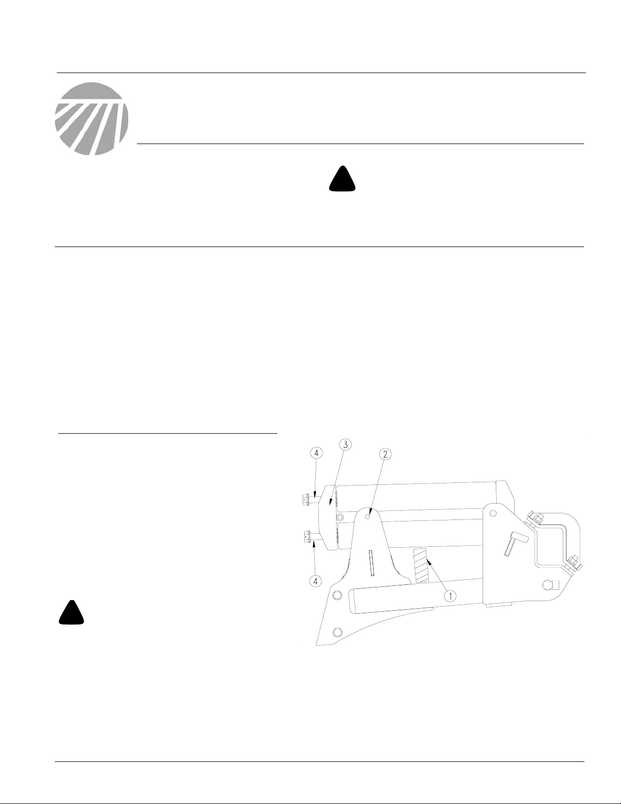
Refer to Figure 1
1. Raise the implement and install transport
locks. Place tractor in park, turn off ignition
and remove the ke y before performing update.
2. Remove the rear 5/8" x 8" bolt (2) and 5/8"
lock nut from the rear spring channel (3).
Keep the bolt and nut f or reuse.
Before You Start
Page 3 is a detailed listing of parts included in the
Auto Reset Bolt Retainer package. Use this list to
inventory parts received.
T ools Required
• Basic hand tools
NOTE: If the 5/8" bolt (2) is binding it will be necessary to adjust the 1" bolts (4) in to relieve pressure on bolt (2).
!
Do Not drive or force bolt (2) out. The stor ed energy of
the springs could cause damage or bodily injury when
released. Use bolts (4) to relieve pressure on bolt (2).
3. Place a block (1) under the spring to support
4. Unscrew the 1" x 14" bolts (4) ev enly from the
© Copyright 2004 Printed
DANGER!
the springs.
springs and remove leaving the spring channel (3) in place. Keep the bolts .
11/17/2004
22808
Figure 1
Remove Bolts
598-026M
Page 2
Auto Reset Bolt Retainer
2
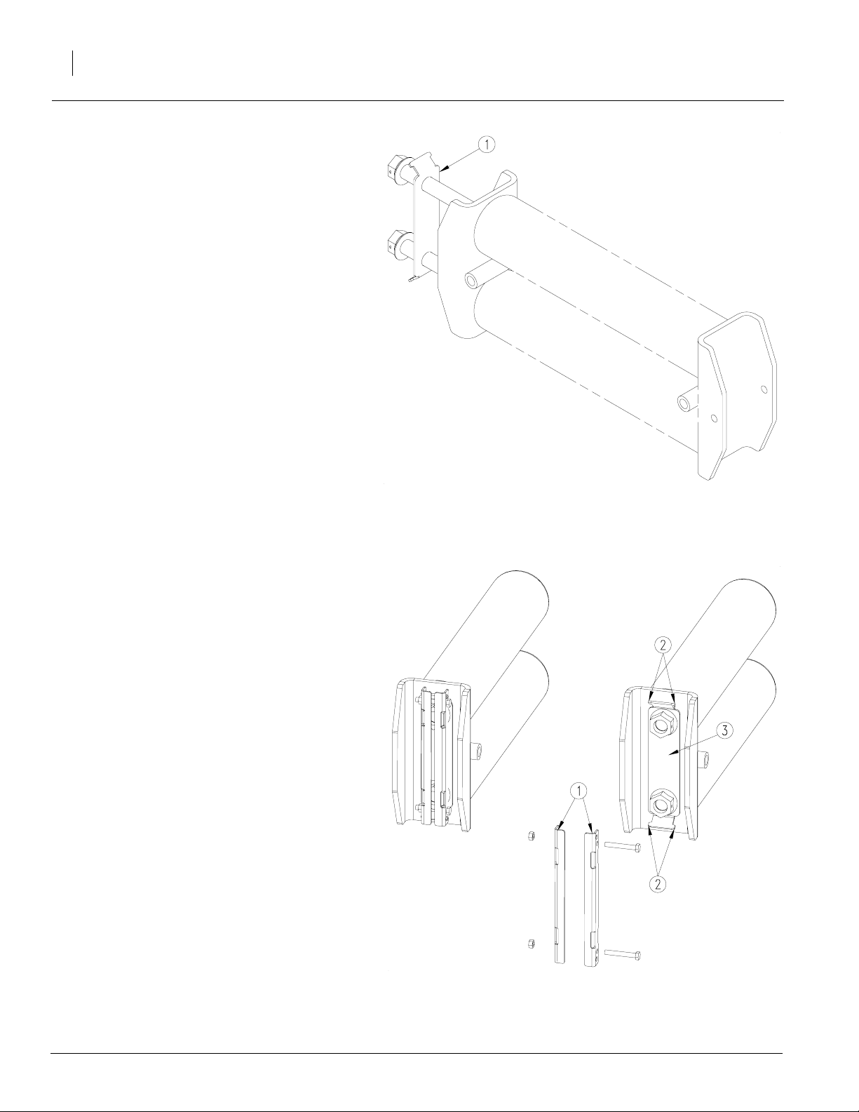
Refer to Figure 2
5. Clean and oil the threads on the 1" x 14" bolts.
6. Place the reset spring lock base (1) on the
bolts which were removed in step f our on
page one. Reinsert the bolts in the springs
and tighten until the hole in the spring channel
aligns with the hole in shank pivot arm. Screw
the bolt heads just enough more so the flats
on the side of each bolt head are aligned
straight up and down.
7. Replace the 5/8" x 8" bolt and lock nut removed in step three on page one and remov e
the block holding the springs.
Great Plains Mfg., Inc.
Refer to Figure 3
8. Assemble the spring lock clamp (1) together
with 5/16" x 2 1/4" bolts and 1/4" lock nuts.
Just finger tighten the nuts for no w.
9. Place the spring lock clamp (1) over the head
of the bolt heads trapping the flats of the bolt.
The tabs (2) on the spring lock base (3) must
stick into the corresponding holes in the lock
clamps (1)
10. Tighten the 5/16" bolts on the spring lock
clamp (1) securely trapping the flats on the
bolt heads.
22809
Figure 2
Install Lock Base
22810
Figure 3
Install Lock Clamp
598-026M 11/29/2004
Page 3

Great Plains Mfg., Inc.
598-025A AUto Reset Bolt Retainer Kit
Your kit includes:
Qty. Part No. Part Description
1 598-026M MANUAL AUTORESET BOLT RETAINER
1 598-046D RESET SPRING LOCK BASE
2 598-047D RESET SPRING LOCK CLAMP
2 802-138C HHCS 5/16-18X2 1/4 GR5
2 803-011C NUT LOCK 5/16-18 PLT
Installation Instructions
3
598-026M11/29/2004
 Loading...