

Great Plains Mfg., Inc.
Installation Instructions
Ace
PTO Sprayer Pump
Used with:
• 3P300
• TA500
• TS750 and TS1000
General Information
When you see this symbol, the subsequent instructions and
warnings areserious- follow without exception. Your life and
!
the lives of others depend on it!
These instructions explainhow to install the Acepump. The
pump is drivenoff the tractor PTO and pressurizes sprayercontents for application.
These instructions apply to:
507-077A PUMP 3PT ACE 540 HIGH VOLUME
507-078A PUMP 3PT ACE 1000 HIGH VOLUME
507-083A PUMP TS ACE150 DRIVE SHAFT
507-084A PUMP TS ACE 1000 1 3/8 DR SHFT
Manual Update
Refer to the sprayer operator’s manual for detailed information
onsafelyoperating, adjusting,troubleshootingand maintaining
the Ace pump. Refer to the parts manualfor part identification.
• 3P300 Operator’s Manual. . . . . . . . . . . . . . . . .500-103M
• 3P300 Parts Manual. . . . . . . . . . . . . . . . . . . . .500-062P
Assembly Instructions
TS750 and TS1000 Pump Assembly
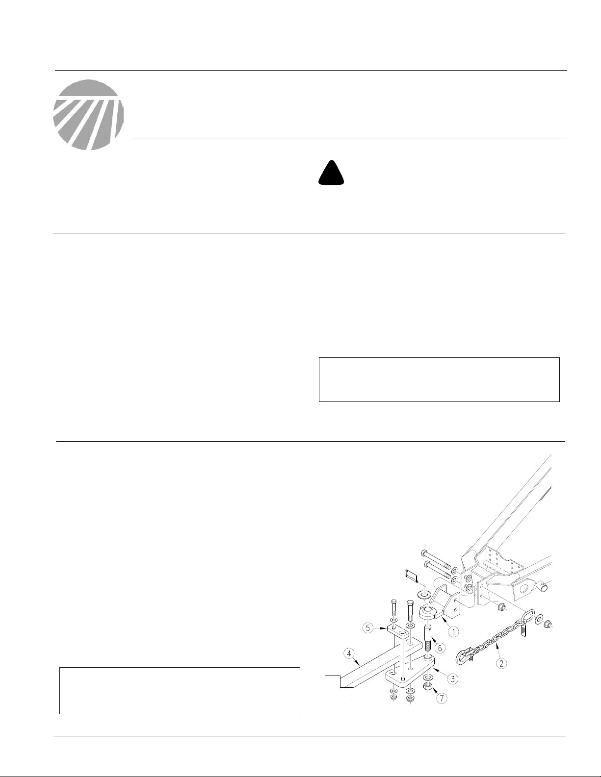
Refer to Figure 1
1. Mount ball hitch(1) on sprayer. Use 1-by-9 1/2-inch bolt,
washers and nuts through top hole to mount hitch and safetychain (2).Use1-by-8-inchbolt,washersandnuts through
lower hole.
2. Bolt hitch plate(3)totractor drawbar (4). Use 3/4-inch bolts
and flange nuts through backup plate (5) and hitch plate as
shown. Use 1-by-5-inch bolt and flange nut through drawbar and hitchplate. Position flat washers onall bolts as
shown.
3. Securehitch pin (6) tohitch plate withflatwasher andnyloninsert nut(7).
4. To hitch sprayerto tractor, slidehitchpinthrough ball swivel
and secure withflat washer and wire lock pin.
• TA500 Operator’s Manual. . . . . . . . . . . . . . . . .500-102M
• TA500 Parts Manual . . . . . . . . . . . . . . . . . . . . .500-061P
• TS750 and TS1000Operator’s Manual . . . . . .500-104M
• TS750 and TS1000Parts Manual . . . . . . . . . .500-071P
Before You Start
Beginningonpage 3 are detailed listingsofpartsincluded in the
Ace pumppackages.Use these lists to inventoryparts received.
Definitions
NOTE: Useful information relatedto the preceding topic.
IMPORTANT: A crucial point of information related to thepreceding topic. F orsafe and correct operation, read and follow
the directions provided before continuing.
IMPORTANT: Use ball hitch shown in Figure 1 inconjunction
with PTO pump . Failure to use ball-hitch with PTO pump will
cause equipment damage and warranty will be voided.
© Copyright 2003 Printed
3/18/2003
17399
Figure 1
TS Hitch Assembly
507-096M
2 ADC2220 Great Plains Manufacturing, Inc.
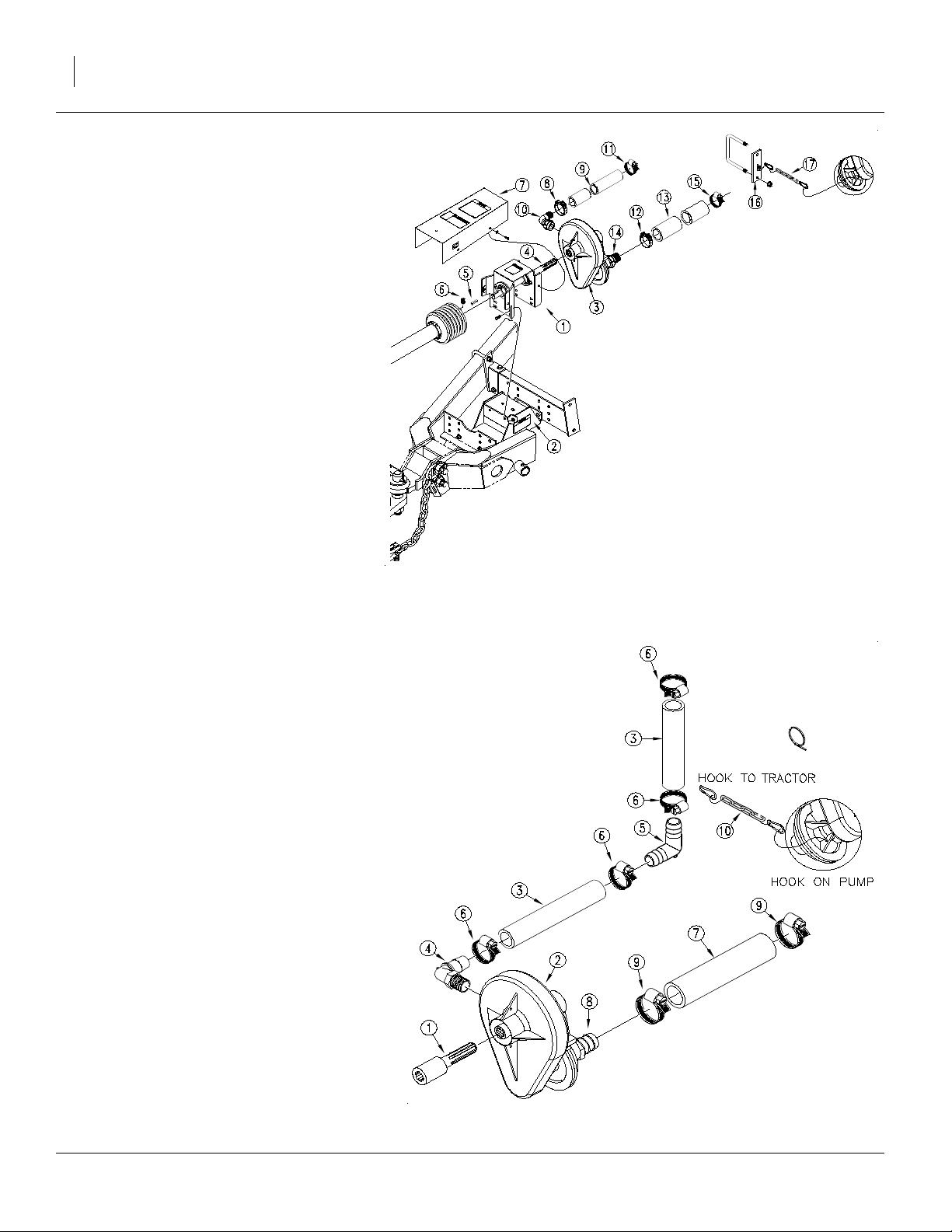
Refer to Figure 2
5. Assembledriveline-bearingmount (1) on pump mount
(2) using 3/8-by-1-inch bolts and flange nuts. Use top
holes of bearing mount.
6. Mount pump (3)onto output shaft of driveline-bearing mount (4).Tighten lock collar on pump.
7. Install key (5) intoinput shaft of driveline-bearing
mount and threadset screws (6) intoyoke of PTO
shaft.Mount PTOshaft onto inputshaftand tighten set
screws.
8. Install driveline shield(7) onto driveline-bearing
mount using 5/16-inchflange bolts and flat
washers.
9. Use smaller t-bolt clamp (8) tosecure11/2-inchhose
(9)to elbow outlet(10)on pump.Use smaller worm
clamp(11) to secureother end ofhoseto Whirlfilter
on sprayer.
10. Use larger t-boltclamp (12) to secure 2-inch
hose (13) topump inlet (14). Use larger worm
clamp (15) to secure other end of hose toadaptor on four-way cross under sprayer.
NOTE:If sprayeris equippedwith aflush-and-rinse
system, secure pumpinlet hose to fitting below
three-way valveon sprayer. Replace elbow (830134C) with straightfitting (830-095C).
11. Assemble pump-chain mount (16) onto right tube of
tongue opposite pump and secure with 1/2-inch u-bolt
and flange nuts. Attach chain (17) betweenpump and
mount as shownand adjust mount accordingly.
12. Tighten all hardware and clamps. Refer to operator’s
manual for operating instructions.
Figure 2
TS750 and TS1000 Pump Assembly
17389
TA500 and 3P300 Assembly
Refer to Figure 3
1. InstallPTOextension(1) on tractorPTOshaft. Tighten
extension set screws.
2. Mount pump (2) on PTO extension. Tighten pump set
screws.
3. Use 1-inch hose(3) to connect pump outlet (4) and
Whirlfilter.If necessary, cut hose intotwosections and
connect with1-inchelbow(5) to avoid hosekinks.Use
worm clamps (6) to secure hosesto fittings.
4. Use 1 1/2-inchhose (7) to connect pump inlet (8)
and sump valve under sprayer tank. Use worm
clamps (9) tosecure hose.
5. TurnPTOshaftbyhandtomakesurethat pumpand its
hardware do not interferewith PTO guards.
6. Hook chain (10)on pump pulley asshown. Anchor
other end ofchain on a secure location on tractor.
7. Secure hoses to sprayer using cable ties provided.
Secure hoses sothey are not kinked,caught or
damaged during sprayer operation.
TA500 and 3P300 Assembly
167-073M 11/10/2008
Figure 3
17390

Great Plains Mfg., Inc.
507-077A Pump 3PT Ace 540 High Volume
Your kit includes:
Qty. Part No. Part Description
1 507-096M MANUAL INSTALL, ACE PUMPS
4 800-082C CABLE TIE .31 X 21.5 6DIA 120LB
4 800-123C CLAMP WRM DRV #16 SS (.68-1.5)
2 800-124C CLAMP WRM DRV #24 SS (1.06-2)
1 826-148C PTO EXTENSION 3 540 RPM
1 830-094C AD 1 1/2MNPT X 1 1/2HB POLPROP
1 830-104C EL 1HB POLYPROP
1 830-129C EL 1 1/4MNPT X 1HB POLYPROP
1 831-010C ACE CENTRIFUGAL - PTO 540
2 890-235C CHAIN LINK SNAP 1/4 PLT
7 990-079R HOSE 1 1/2ID EPDM SUCTION
4 990-082R HOSE 1 ID 200PSI EPDM
2 990-086R CHAIN 2/0 STRAIGHT LINK PLT
Installation Instructions
3
507-078A Pump 3PT Ace 1000 High Volume
Your kit includes:
Qty. Part No. Part Description
1 507-096M MANUAL INSTALL, ACE PUMPS
4 800-082C CABLE TIE .31 X 21.5 6DIA 120LB
4 800-123C CLAMP WRM DRV #16 SS (.68-1.5)
2 800-124C CLAMP WRM DRV #24 SS (1.06-2)
1 826-149C PTO EXTENSION 3 1000 RPM
1 830-094C AD 1 1/2MNPT X 1 1/2HB POLYPROP
1 830-104C EL 1HB POLYPROP
1 830-129C EL 1 1/4MNPT X 1HB POLYPROP
1 831-011C ACE CENTRIFUGAL - PTO 1000
2 890-235C CHAIN LINK SNAP 1/4 PLT
7 990-079R HOSE 1 1/2ID EPDM SUCTION
4 990-082R HOSE 1 ID 200PSI EPDM
2 990-086R CHAIN 2/0 STRAIGHT LINK PLT
507-096M11/10/2008

PTO Sprayer Pump
4
507-083A Pump TS Ace 150 540 Drive Shaft
Your kit includes:
Qty. Part No. Part Description
1 161-104D 5/16 SQ CR X 1 1/2 LONG
1 500-077H HITCH - BALL
1 500-078H BALL HITCH PLATE WELDMENT
1 500-087D BALL HITCH BACKUP PLATE
1 500-088D PIN - BALL HITCH
1 507-017D SHIELD - TA DRIVELINE 540 RPM
1 507-041D CHAIN - PUMP MOUNT
1 507-086K TS DRIVELINE BRG MNT ASSY
1 507-088H BRACKET - TS PUMP CHAIN MOUNT
1 507-096M MANUAL INSTALL, ACE PUMPS
2 800-125C CLAMP WRM DRV#28 SS(1.31-2
2 800-144C CLAMP WRM DRV #40 SS (2.06
1 800-207C CLAMP T-BOLT STRAP (2.18-2
1 800-208C CLAMP T-BOLT STRAP (1.81-2
2 801-023C SCREW SET SH 3/8-16X3/8
4 802-017C HHCS 3/8-16X1 GR5
2 802-069C HHCS 3/4-10X5 GR5
1 802-235C HHCS 1-8X5 GR5
4 802-387C HFS 5/16-18X3/4 GR5
4 803-068C NUT HEX FLANGE 3/8-16 PLT
1 803-081C NUT HEX 1 1/4-7 NYLON INSERT
6 803-193C NUT HEX FLANGE 1/2-13 GR G
1 803-206C NUT HEX FLANGED 1-8 PLT
2 803-214C NUT HEX FLANGE 3/4-10 GR5
4 804-024C WASHER FLAT 3/4 USS PLT
2 804-028C WASHER FLAT 1 USS PLT
1 804-035C WASHER FLAT 1 1/4 USS PLT
4 804-036C WASHER FLAT 5/16 SAE PLT
1 804-114C WASHER FLAT 1 3/4HARD ASTM
1 805-178C PIN WIRE SNAP LOCK 3/8 X
1 806-067C U-BOLT 1/2-13 X 6 1/32 X 4
1 818-142C DECAL DANGER PTO DRIVELINE
1 818-349C DECAL GREASE 10 HRS LH
1 818-464C DECAL DRVLNE ATTACH SPECS
1 826-238C PTO 540 2200 X 27.95 NO CL
1 830-095C AD 2MNPT X 2HB POLYPROP
1 830-131C EL 1 1/4MNPT X 1 1/2HB POLYPROP
1 830-304C 1 1/2 MNPT X 2HB
1 831-010C ACE CENTRIFUGAL - PTO 540
2 890-235C CHAIN LINK SNAP 1/4 PLT
6 990-124R HOSE 2 ID EPDM SUCTION
2 990-181R HOSE 1 1/2 ID 150PSI EPDM
Great Plains Mfg., Inc.
11/10/2008
507-096M

Great Plains Manufacturing, Inc. 5
507-084A Pump TS Ace 150 1000 1-3/8 Drive Shaft
Your kit includes:
Qty. Part No. Part Description
1 161-104D S2 B 1.0000 EA 5/16 SQ CR X 1 1/2 LONG
1 500-077H S2 M 1.0000 EA HITCH - BALL
1 500-078H S2 M 1.0000 EA BALL HITCH PLATE WELDMENT
1 500-087D S2 M 1.0000 EA BALL HITCH BACKUP PLATE
1 500-088D S2 M 1.0000 EA PIN - BALL HITCH
1 507-018D S2 M 1.0000 EA SHIELD - TA DRIVELINE 1000 RPM
1 507-041D S2 M 1.0000 EA CHAIN - PUMP MOUNT
1 507-087K S2 M 1.0000 EA TS DRIVELINE BRG MNT ASSY 1
1 507-088H S2 M 1.0000 EA BRACKET - TS PUMP CHAIN MOUNT
1 507-096M S2 M 1.0000 EA MANUAL INSTALL, ACE PUMPS
1 800-125C S2 B 2.0000 EA CLAMP WRM DRV#28 SS(1.31-2.
1 800-144C S2 B 2.0000 EA CLAMP WRM DRV #40 SS (2.06 1 800-207C S2 B 1.0000 EA CLAMP T-BOLT STRAP (2.18-2.
1 800-208C S2 B 1.0000 EA CLAMP T-BOLT STRAP (1.81-2.
1 801-023C S2 B 2.0000 EA SCREW SET SH 3/8-16X3/8
1 802-017C S2 B 4.0000 EA HHCS 3/8-16X1 GR5
1 802-069C S2 B 2.0000 EA HHCS 3/4-10X5 GR5
1 802-235C S2 B 1.0000 EA HHCS 1-8X5 GR5
1 802-387C S2 B 4.0000 EA HFS 5/16-18X3/4 GR5
1 803-068C S2 M 4.0000 EA NUT HEX FLANGE 3/8-16 PLT
1 803-081C S2 B 1.0000 EA NUT HEX 1 1/4-7 NYLON INSERT
1 803-193C S2 B 6.0000 EA NUT HEX FLANGE 1/2-13 GR G
1 803-206C S2 B 1.0000 EA NUT HEX FLANGED 1-8 PLT
1 803-214C S2 B 2.0000 EA NUT HEX FLANGE 3/4-10 GR5 P
1 804-024C S2 B 4.0000 EA WASHER FLAT 3/4 USS PLT
1 804-028C S2 B 2.0000 EA WASHER FLAT 1 USS PLT
1 804-035C S2 B 1.0000 EA WASHER FLAT 1 1/4 USS PLT
1 804-036C S2 B 4.0000 EA WASHER FLAT 5/16 SAE PLT
1 804-114C S2 B 1.0000 EA WASHER FLAT 1 3/4HARD ASTMF
1 805-178C S2 B 1.0000 EA PIN WIRE SNAP LOCK 3/8 X
1 806-067C S2 B 1.0000 EA U-BOLT 1/2-13 X 6 1/32 X 4
1 818-142C S2 B 1.0000 EA DECAL DANGER PTO DRIVELINE
1 818-349C S2 B 1.0000 EA DECAL GREASE 10 HRS LH
1 818-465C S2 B 1.0000 EA DECAL DRVLNE ATTACH SPECS 1
1 826-239C S2 B 1.0000 EA PTO 1000 2200X 29.92 NO CLU
1 830-095C S2 B 1.0000 EA AD 2MNPT X 2HB POLYPROP
1 830-131C S2 B 1.0000 EA EL 1 1/4MNPT X 1 1/2HB POLYPROP
1 830-304C S2 B 1.0000 EA 1 1/2 MNPT X 2HB
1 831-011C S2 B 1.0000 EA ACE CENTRIFUGAL - PTO 1000
1 890-235C S2 B 2.0000 EA CHAIN LINK SNAP 1/4 PLT
1 990-124R S2 B 6.8330 FT HOSE 2 ID EPDM SUCTION
1 990-181R S2 B 2.4160 FT HOSE 1 1/2 ID 150PSI EPDM
11/10/2008 167-073M

Great Plains Manufacturing, Inc.
Corporate Office: P.O. Box 5060
Salina, Kansas 67402-5060 USA
 Loading...