

Page 1
Operator’ s Manual
AS15 and AS20
Planting System
Manufacturing, Inc.
www .g reatplainsmfg.com
Read the operator’s manual entirely. When you see this symbol, the subsequent in-
!
structions and warnings are serious -follow without exception. Your life and thelivesof
others depend on it!
© Copyright 1998 Printed
4/14/2005
13621
Cover illustration may show optional equipment not supplied with standard unit.
148-153M
Page 2

General Information
General Information
Important Notice
Great Plains Manufacturing, Inc. provides this publication “as is” without warranty of any kind, either
expressed or implied, while every precaution has been
taken in the preparation of this manual, Great Plains
Manufacturing,Inc. assumes no responsibility for errors
oromissions.Neither is any liability assumed for damages resulting from the use of the information contained
herein. Great Plains Manufacturing, Inc. reserves the
righttoreviseand improveitsproductsasitseesfit.This
This Operator’s Manual applies to:
The 15’ All Seeds Hitch
The 20’ All Seeds Hitch
Owner’s Information
publicationdescribesthe state of this product atthetime
of its publication, and may not reflect the product at all
times in the future.
Printed in the United States of America.
For your convenience, record your Serial Number,Mod-
el Number and the Date Purchased in the spaces
provided below. Have this information before you when
calling a Great Plains Authorized Dealer.
Name: _____________________________________
Address ____________________________________
City________________State ____ Zip ___________
Phone_______________________
Name of Dealership ___________________________
Dealer’s Name _______________________________
Address ____________________________________
City________________State ____ Zip ___________
Phone_______________________
Serial Number _______________________________
Model Number_______________________________
Date Purchased______________________________
AS15 and AS20 Planting System 148-153M 4/14/05Great Plains Mfg., Inc.
Page 3

Table of Contents
Table of Contents
Using this Manual . . . . . . . . . . . . . . . . . . . . .2
Introduction . . . . . . . . . . . . . . . . . . . . . . . . .2
Section 1 Safety Rules . . . . . . . . . . . . . . . . . . 3
Safety Decals . . . . . . . . . . . . . . . . . . . . . . . 3
Section 2 Assembly Instructions & Set-Up. . 6
Torque Values Chart . . . . . . . . . . . . . . . . . 6
Tire Inflation Chart . . . . . . . . . . . . . . . . . . . .6
Assembling The All Seeds Hitch. . . . . . . . . 8
Tractor Drawbar Hookup. . . . . . . . . . . . . . . 8
Tractor Hydraulic Hookup . . . . . . . . . . . . . 10
Bleeding The Hydraulic Systems . . . . . . . 10
Drill and Planter Hookup. . . . . . . . . . . . . . 11
Transporting . . . . . . . . . . . . . . . . . . . . . . . 14
Section 3 Basic Operation . . . . . . . . . . . . . . 14
Pre Drilling/Planting Instructions. . . . . . . . 15
Basic Operating Rules. . . . . . . . . . . . . . . . 15
Operating Checklist . . . . . . . . . . . . . . . . . 17
Section 4 Hitch, Drill, & Planter Adjustments
For No-Till Planting Conditions . . . . . . . . . . 18
Hitch Adjustments . . . . . . . . . . . . . . . . . . . 18
Drill & Coulter Adjustments . . . . . . . . . . . . 19
Planter & Coulter Adjustments. . . . . . . . . . 22
Section 5 Maintenance & Lubrication . . . . . 25
General Maintenance . . . . . . . . . . . . . . . . 25
Storage . . . . . . . . . . . . . . . . . . . . . . . . . . . 25
Lubrication. . . . . . . . . . . . . . . . . . . . . . . . . 25
Section 6 Troubleshooting . . . . . . . . . . . . . . 29
Section 7 Options. . . . . . . . . . . . . . . . . . . . . . 30
Section 8 Specifications & Warranty . . . . . . 32
Warranty . . . . . . . . . . . . . . . . . . . . . . . . . . 33
4/14/05 Great Plains Mfg., Inc.
AS15 and AS20 Planting System 148-153M
-1
Page 4
Using this Manual
Using this Manual
For your safety and to help in developinga better understanding of your equipment we highly recommend that
you read the operator sections of this manual. Reading
these sections not only provides valuable training but
also familiarizes you with helpful information and its lo-
Introduction
This manual has been prepared to instruct you in the
safe and efficient operation of your All Seeds Hitch.
Read and follow all instructions and safety precautions
carefully.
The parts on your All Seeds Hitch have been specially
designed and should only be replaced with genuine
Great Plains parts. Therefore, should your
All Seeds Hitch require replacement parts go to your
Great Plains Dealer.
The right hand and left hand as used throughout this
manual is determined by facing in the direction the machine will travel when in use unless otherwise stated.
Serial Number
The serial number plate is located on the front of the
Coulter Tool Bar support tube next to the 8" x 8" hitch
tubeItissuggestedthat the serialnumber andpurchase
datealso be recorded for your convenienceinthe space
provided on the checklist page at the beginning of this
manual.
Theserial number provides importantinformation about
your All Seeds Hitch and may be required to obtain the
correct replacement part. Alwaysuse the serial number
and model number when sending correspondence or
when ordering parts from your Great Plains Dealer.
cation. The parts sections are for reference only and
don’trequire covertocoverreading.Afterreviewingyour
manual store it in a dry,easily accessible location for future reference.
lows it. In addition to design and configuration of
equipment; hazard control and accident prevention are
dependentupon the awareness,concern,prudence and
proper training of personnel involved in the operation,
transport, maintenance and storage of equipment.
Watchforthe followingsafety notations through-out
your Operators Manual:
!
DANGER!
Indicates an imminently hazardous situation which, if
not avoided, will result in death or serious injury. This
signal word is limited to the most extreme situations.
!
WARNING!
Indicates a potentially hazardoussituation which, if not
avoided, could result in death or serious injury.
!
Indicates a potentially hazardoussituation which, if not
avoided, may result in minor or moderate injury.It may
also be used to alert against unsafe practices.
CAUTION!
!
The SAFETY ALERT SYMBOL indicates that there is a
potential hazard to personal safety involved and extra
safety precautions must be taken. When you see this
symbol, be alertand carefully read themessage that fol-
2
AS15 and AS20 Planting System 148-153M 4/14/05
NOTE: Indicates a special point of information which
requires your attention.
Great Plains Mfg., Inc.
Page 5

Section 1 Safety Rules
Section 1 Safety Rules
Most accidents are the result of negligence and carelessness, usually caused by failure of the operator to
follow simple but necessary safety precautions. The followingsafetyprecautions are suggested to help prevent
such accidents. The safeoperation of any machinery is
a big concern to consumers and manufactures.Your All
SeedsHitch has beendesignedwithmany built-insafety
features. However, no one should operate this product
before carefully reading this Operators Manual.
!
General Operation & Repair
1. Never permit anyone to ride on or walk beside the drill,
planter, or tillage equipment when moving.
2. Never permit anyone to ride on tractor, drill, planter or
hitch when they are being moved.
3. Never allow anyone to be near the drill or planter when
performing operating functions with the drill, planter,
hitch, or tractor.
4. Never load the drill or planter without being hooked up
to a tractor.
5. Always make sure the drill and planter are securely
locked in the quick hitch before raising.
6. Always put the transport lock lever into the transport
“Road” position and make sure transport lock blocks
havesnapped intotheir locked positionimmediately after
raising the unit for transporting and before making
adjustments.
7. Nevertransport the AllSeeds Hitch withoutthe pivot lock
tubes (correctly adjusted), and in the horizontal (locked)
position. The pivot lock tubes are located above and outside of the leaf springs. The lock tubes will lock automatically when the unit is raised, unless they are manually
pinned in the vertical position.
8. Extra care should be taken when transporting with seed
in the box or hoppers.
9. Reduce speed of the tractor when transporting over uneven or rough terrain, hills or steep slopes. Avoid all
chuck holes and washboard areas in roads.
10. Do not pull the All Seeds Hitch faster than 20 miles per
hour.
11. Never turn a shorter radiusthan the All SeedsHitch pivot
stops will allow.
12. When in transport, use accessory lights and devices for
adequate warning to operators of other vehicles and use
safety hitch chain. Comply with all federal, state and local laws when traveling on public roads.
13. Use “slow moving vehicle” emblem for warning vehicles
approaching from the rear.
14. When transporting, remember the All Seeds Hitch is wider than your tractor and extreme care must be taken to
allow for safe clearance.
15. Never back up with the drill openers, planter openers or
coulters in the ground.
16. Always set the drill or planter in the field position before
lubrication, making adjustments, or servicing. Periodically check bolts for tightness and lubricate all fittings.
17. Do not lubricate or adjust the drill or planter while it is
in operation.
18. Do not permit smoking, sparks, or an open flame where
combustible lubricants or liquids are being used.
19. When using treated seed, avoid direct contact with the
seed. Do not breath or ingest chemicals.
20. When using compressed air to clean the drill boxes or
planter hoppers wear safety glasses.
21. Never unhook hitch from tractor when attached to a
raised drill or planter.
22. Escaping fluid under pressure can have sufficient force
to penetrate the skin. Check all hydraulic lines and hoses
before applying pressure. Fluid escaping from a very
small hole can be almost invisible. Use paper or cardboard, not body parts, to check for suspected leaks. If injured, seek medical assistance from a doctor that is
familiar with this type of injury. Foreign fluids in the tissue must be surgically removed within a few hours or
gangrene will result.
23. Do not allow anyone to operate the machine who has not
been properly trained in its safe operation.
24. Consult your drill operator’s manual for safe drill operation.
25. Consult your planter operator’s manual for safe planter
operation.
26. Do not operate equipment while under the influence of
drugs or alcohol.
27. Keep hands, feet, hair, and clothing away from all moving parts.
28. Clear the area of bystanders, especially small children
and animals before moving or operating equipment.
29. Support implement with blocks or safety stands when
changing tires or working on equipment.
30. Review the Safety instructions annually.
Safety Decals
1. Your All Seeds Hitch comes equipped with all safety decals in place. They were designed to help you safely operate your All Seeds Hitch. Read and follow their
directions.
2. Keep safety decals clean and legible.
3. Replace all damaged or missing safety decals. To order
new safety decals go to your Great Plains Dealer and orderpart no. 148-179A. Refer tothe parts section for Alldecals package part numbers.
4. Replace these decals whenever they become worn or unreadable. To instal new safety decals:
a. Clean the area the decal is to be placed
b. Peel backing from the decal. Press firmly on to sur-
face being careful not to cause air bubbles under the
decal.
4/14/05 Great Plains Mfg., Inc.
AS15 and AS20 Planting System 148-153M
-3
Page 6
Section 1 Safety Rules
12306
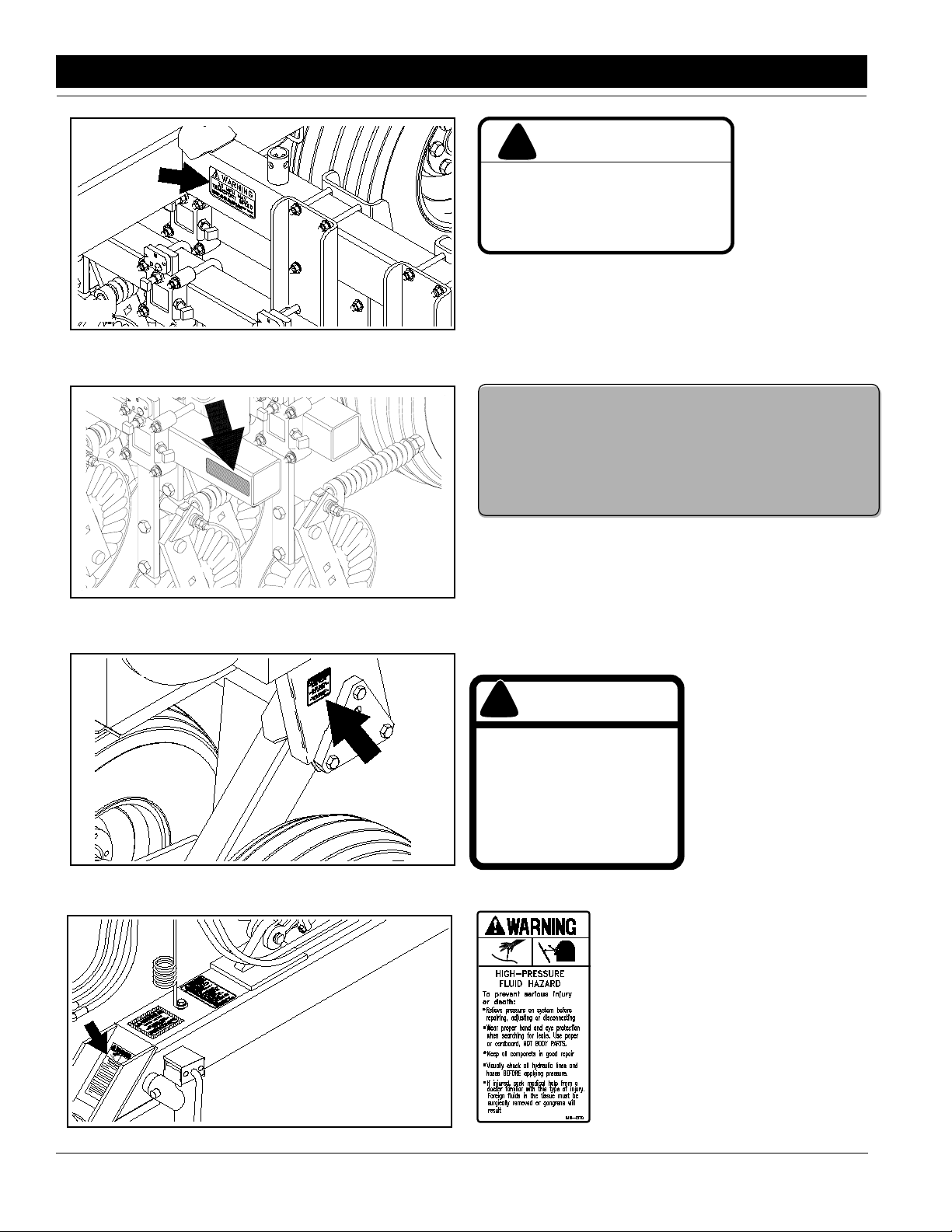
!
WARNING
20 MPH MAX.
TRANSPORT SPEED
EXCEEDING 20 MPH MAY RESULT IN LOSS OF VEHICLE
CONTROL AND/OR IMPLEMENT DAMAGE
818-188C
Transport Speed Warning
818-188C
12307
12309
838-265C
Amber Reflector
CAUTION
!
AVOID INJURY
DO NOT STAND ON
TRANSPORT TIRESOR USE
TIRES AS A STEP
THE TIRES MAY NOT BE IN
CONTACT WITH THE GROUND AND
WILL
ROTATE EASILY
818-398C
818-398C
Caution - Tires Not A Step
818-437C
12308
4
AS15 and AS20 Planting System 148-153M 4/14/05
Warning - High Pressure
12423
Great Plains Mfg., Inc.
Page 7
Section 1 Safety Rules
12447
! !
WARNING
SAFETY HAZARD
USE EXTREME CAUTION
WHEN UNHITCHING IMPLEMENT
FROM TRACTOR.
Negative tongue weight may cause immediate
elevation of tongue resulting
in damage or personal injury.
818-019C
818-019C
Warning - Negative Tongue Weight
12448
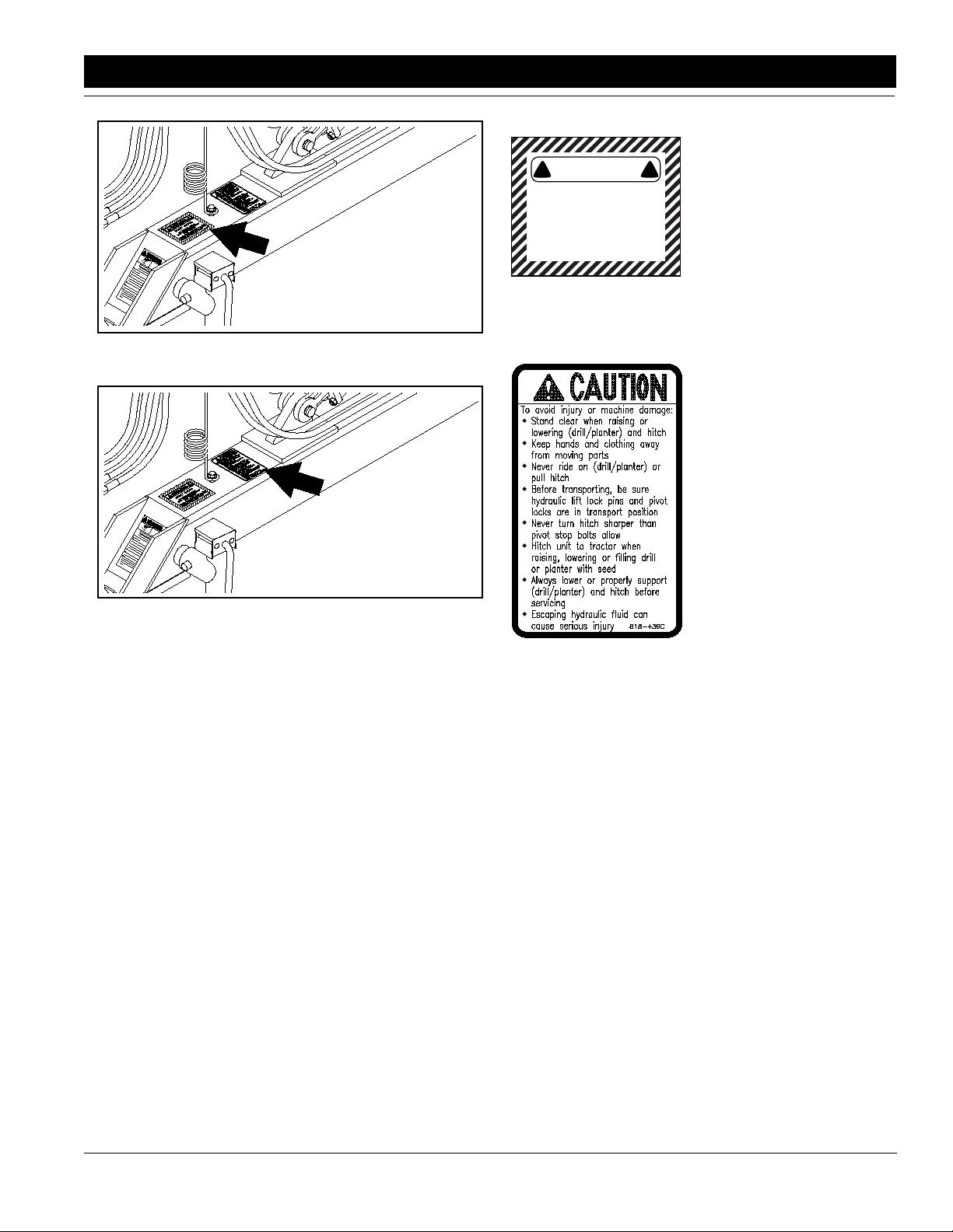
818-439C
All Seeds General Caution
12424
4/14/05 Great Plains Mfg., Inc.
AS15 and AS20 Planting System 148-153M
-5
Page 8
Section 2 Assembly Instructions & Set-Up
Section 2 Assembly Instructions & Set-Up
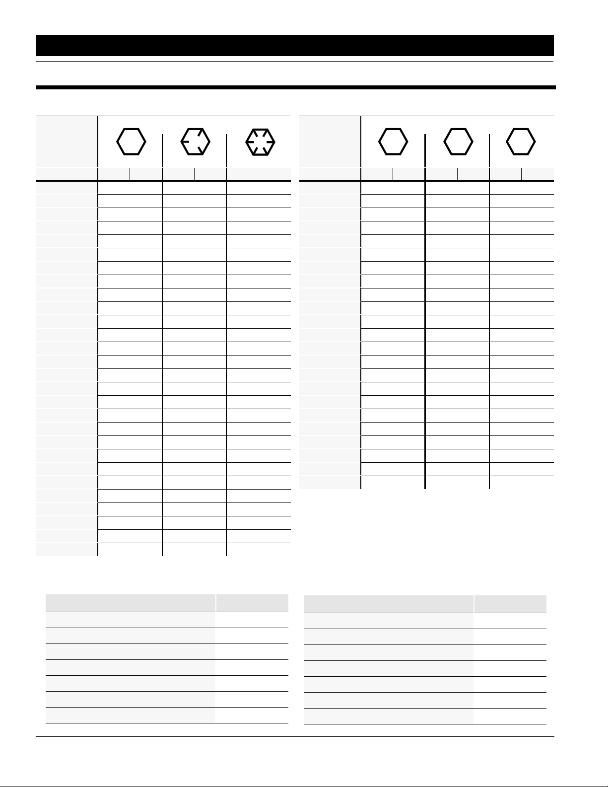
Torque Values Chart for Common Bolt Sizes
Bolt Head Identification
Bolt Head Identification
Bolt Size
(Inches)
1
in-tpi
1/4" - 20 7.4 5.6 11 8 16 12 M 5 X 0.8 436597
1/4" - 28 8.5 6 13 10 18 14 M 6 X 1 7 5 11 8 15 11
5/16 - 18 15 11 24 17 33 25 M 8 X 1.25 17 12 26 19 36 27
5/16" - 24 17 13 26 19 37 27 M 8 X 1 18 13 28 21 39 29
3/8" - 16 27 20 42 31 59 44 M10 X 1.5 33 24 52 39 72 53
3/8" - 24 31 22 47 35 67 49 M10 X 0.75 39 29 61 45 85 62
7/16" - 14 43 32 67 49 95 70 M12 X 1.75 58 42 91 67 125 93
7/16" - 20 49 36 75 55 105 78 M12 X 1.5 60 44 95 70 130 97
1/2" - 13 66 49 105 76 145 105 M12 X 1 90 66 105 77 145 105
1/2" - 20 75 55 115 85 165 120 M14 X 2 92 68 145 105 200 150
9/16" - 12 95 70 150 110 210 155 M14 X 1.5 99 73 155 115 215 160
9/16" - 18 105 79 165 120 235 170 M16 X 2 145 105 225 165 315 230
5/8" - 11 130 97 205 150 285 210 M16 X 1.5 155 115 240 180 335 245
5/8" - 18 150 110 230 170 325 240 M18 X 2.5 195 145 310 230 405 300
3/4" - 10 235 170 360 265 510 375 M18 X 1.5 220 165 350 260 485 355
3/4" - 16 260 190 405 295 570 420 M20 X 2.5 280 205 440 325 610 450
7/8" - 9 225 165 585 430 820 605 M20 X 1.5 310 230 650 480 900 665
7/8" - 14 250 185 640 475 905 670 M24 X 3 480 355 760 560 1050 780
1" - 8 340 250 875 645 1230 910 M24 X 2 525 390 830 610 1150 845
1" - 12 370 275 955 705 1350 995 M30 X 3.5 960 705 1510 1120 2100 1550
1-1/8" - 7 480 355 1080 795 1750 1290 M30 X 2 1060 785 1680 1240 2320 1710
1 1/8" - 12 540 395 1210 890 1960 1440 M36 X 3.5 1730 1270 2650 1950 3660 2700
1 1/4" - 7 680 500 1520 1120 2460 1820 M36 X 2 1880 1380 2960 2190 4100 3220
1 1/4" - 12 750 555 1680 1240 2730 2010
1 3/8" - 6 890 655 1990 1470 3230 2380
1 3/8" - 12 1010 745 2270 1670 3680 2710
1 1/2" - 6 1180 870 2640 1950 4290 3160
1 1/2" - 12 1330 980 2970 2190 4820 3560
Grade 2 Grade 5
N · m2ft-lb3N · m ft-lb N · m ft-lb mm x pitch
Grade 8
Bolt Size
(Metric)
4
1
in-tpi = nominal thread dia .in inches-threads per inch
2
N· m = newton-meters
3
ft-lb= foot pounds
4
mm x pitch = nominal thread dia. in millimeters x thread pitch
5.8 8.8 10.9
Class 5.8 Class 8.8 Class 10.9
N · m ft-lb N · m ft-lb N · m ft-lb
Tire Inflation Chart
Tire Size Inflation PSI
7.50 x 20" 4-Ply Drill Rib 28
9.0 x 22.5 10-Ply Highway Service 70 70
9.0 x 24" 8-Ply Rib Implement 40
9.5L x 15" 6-Ply Rib Implement 32
9.5L x 15" 8-Ply Rib Implement 44
9.5L x 15" 12-Ply Rib Implement 60
5.00 x 15" 4-Ply T r action Type Implement 36
6
AS15 and AS20 Planting System 148-153M 4/14/05
Tire Size Inflation PSI
11L x 15" 6-Ply Rib Implement 28
11L x 15" 12-Ply Rib Implement 52
11L x 15" 18-Ply Rib Implement 76
12.5L x 15" 8-Ply Rib Implement 36
12.5L x 15" 10-Ply Rib Implement 44
16.5L x 16.1" 10-Ply Rib Implement 36
41 x 15" x 18 - 22-Ply Rib Implement 44
Great Plains Mfg., Inc.
Page 9

Section 2 Assembly Instructions & Set-Up
NOTE: All tires are warranted by the original manufacturer of the tire. Tire warranty information can be found in the
brochures included with your Operator’s and Parts Manuals or online at the manufacturer’s websites. For service assistance or information, contact your nearest Authorized Farm Tire Retailer.
Manufacturer Websites
Titan www.titan-intl.com
Goodyear www.goodyearag.com
Firestone www.firestoneag.com
4/14/05 Great Plains Mfg., Inc.
AS15 and AS20 Planting System 148-153M
-7
Page 10
Section 2 Assembly Instructions & Set-Up
Read and understand the owner’s manual for your All
Seeds Hitch. A basic understanding of how the hitch
works will aid in the assembly and setup of your hitch.
The followinginformation is general in nature and was
written to aid the operator in preparation of the tractor
Pre-Assembly Checklist
Check Reference
All major components Operator’s
Fasteners that were shipped with the All
Seeds Hitch.
NOTE: Some of the hardware from the
factory has been installed in the location
where it will be used.
Have a minimum of 2 people at hand while
assembling the All Seeds Hitch.
Manual
Section
page 9
Section 2
page 8
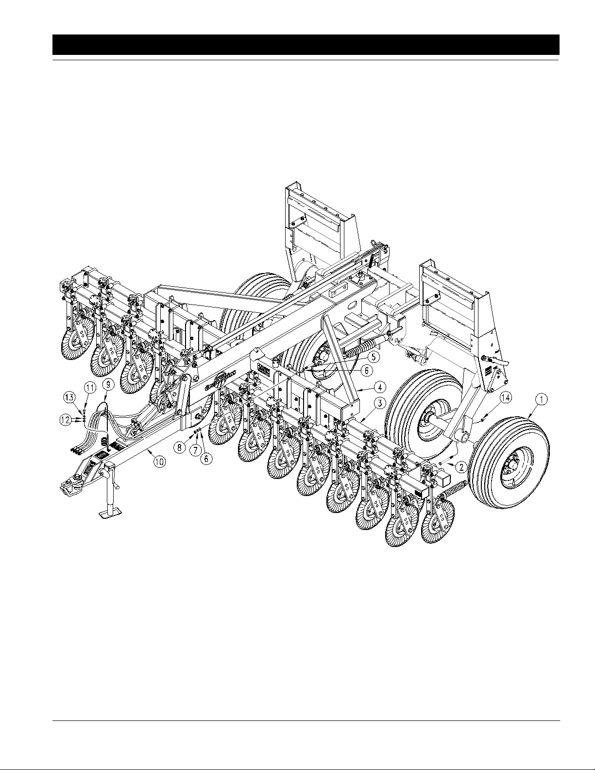
Assembling The All Seeds Hitch
For the following assembly instructions refer to Figure 2-2.
1. Remove the transport tire, hub, and spindle assemblies(#1) whicharebandedto the hitchandslidethe
spindlesintothe outer spindle tubes of the transport
rockshaft.Secure the spindles in place with the 1/2"
x 4 3/4" long bolts (#2) and the 1/2" lock nuts (#14).
Cut the bands that hold the tongue and tongue cylinder to the hitch and swing it into position and pin
the cylinder to the cylinder lug on the hitch. Swing
the tongue links into position and bolt them to the
ears on the front tongue.
2. Center the coulter tool bar assembly (#3) under the
hitch (#4) and fasten to upper coulter tool bar support with the 5/8” x 6” long bolts (#5), 5/8” flat washers (#6), 5/8” lock washers (#7), and 5/8" nuts (#8).
It is criticalthat the coulters are centered under the
All Seeds Hitch to insure proper tracking with the
drill. Use extra care when assembling the coulter
tool bar assembly to the hitch. The coulter tool bar
assemblies should have a coulter blade gap centered on the center line of the hitch.
and hitch for use, and to provide general operating procedures. The operator’s experience, familiarity with the
machine and the following information should combine
for efficient hitch operation and good working habits.
Having all the parts and equipment readily at hand will
speed up your assembly task.
Check Reference
Havea fork lift or loader along with chains
and safety stands ready for the assembly
task.
If you are unsure where a fastener is
used, use the partssection of this manual
to identify it. Be sure the part gets used in
the correct location.
Section 1
page 3
Parts Manual
263M)forassembly of optional Coulter Depth Control
Attachments.
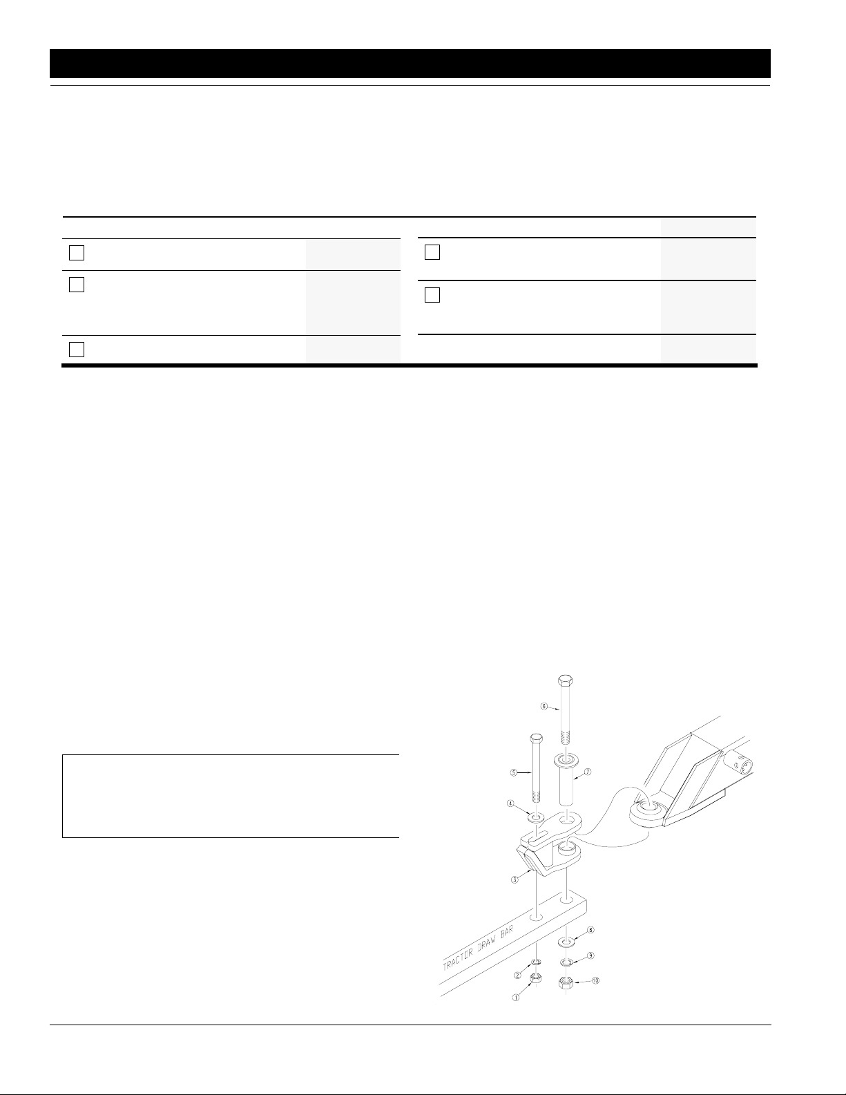
Tractor Drawbar Hookup
For the followingassembly instructions refer to Figure 2-1.
1. Place hitch weldment (#1) over the ball swivel of the
front hydraulictongue and hold in place by inserting
theinner spacer tubeweldment(#2) through the large
hole in the hitch clevis and ball swivel.
2. Back tractor up to the machine and bolt hitch weldmentassembly (#1)&(#2) to tractordrawbarlargepin
holeusingthe1"x10"longbolt(#3),largeflatwasher
(#4), 1" lock washer (#5), and 1" nut (#6). Use 3/4" x
9" long bolt (#7) to bolt the hitch weldment through its
slotted hole and into thesecondary hole of the tractor
drawbar. Install a 3/4" flat washer (#8) nextto the top
slotted hole and fasten with a 3/4" lock washer (#9)
and 3/4" nut (#10). Tighten both bolts.
NOTE: The center of the coulter blade is approximately 1/4" to the right of the coulter mount casting
and coulter spring bar.
3. Assemblethe springhose loop (#9) on the hydraulic
tongue(#10)witha 1/2" x 1" long bolt (#11), two 1/2"
flat washers (#12), and a 1/2" lock washer (#13).
The spring hose loop bolts to a coupler nut welded
near the front of the hydraulic tongue.
Drawbar
Assembly Illustration
Figure 2-1
4. Referto Fertilizer Option Manual (GP 148-152M) for
assembly of optional Liquid Fertilizer Attachments.
5. Referto Coulter Command Option Manual(GP 148-
8
AS15 and AS20 Planting System 148-153M 4/14/05
Great Plains Mfg., Inc.
12073
Page 11
Section 2 Assembly Instructions & Set-Up
13620
M
E
T
S
Y
S
G
N
I
T
N
A
L
P
S
D
E
E
S
L
L
A
Dealer Assembly Illustration
Figure 2-2
4/14/05 Great Plains Mfg., Inc.
AS15 and AS20 Planting System 148-153M
-9
Page 12

Section 2 Assembly Instructions & Set-Up
Your AllSeedsHitch comes equipped with a hitch safety
chain. The safety chain should be securely attached to
the All Seeds Hitch and the tractor drawbar whenever
towing or planting.
Remove the jack from the storage position on the front
hydraulictongue as shown in Figure 2-3 and place in the
transport position on top of the coulter tool bar support
tube as shown in Figure 2-4.
12084
Jack In Storage Position
Figure 2-3
Tractor Hydraulic Hookup
The tractor should be equipped with 4 remote outlets (2
pair). The 1/2" hoses from the front tongue cylinder connect to one set of tractor remote outlets. The 1/2" hoses
from the transportlift cylinders connect to another set of
tractor remote outlets.
Bleeding The Hydraulic Systems
!
WARNING!
Escaping fluidunder pressurecan have sufficient forceto penetrate the skin. Check all hydraulic lines and hoses before applying pressure. Fluid escaping from a very small hole can be
almost invisible. Use paper or cardboard, not body parts, to
check for suspected leaks. If injured, seek medical assistance
froma doctor that is familiar with this kind of injury. Foreign
fluids in the tissue must be surgically removed within a few
hours or gangrene will result.
Front Hydraulic Tongue Cylinder
NOTE: Check the hydraulic fluid in the tractor reservoir and fill to the proper level. Add fluid to the system as needed. A low reservoir level may draw air
back into the system, causing jerky or uneven cylinder movement. Front tongue cylindercapacity is 0.5
gallons.
1. Raise and safely support hitch, transport frame and
front tongue in order to unpin the rod end of the
tongue cylinder. Block, wire or otherwise safelysupport the cylinder so when the rod end is fully extended it does not contact anything.
2. Cycle the cylinder completely in and out a minimum
of three times to purge the air from the cylinder and
hoses.
3. Fully extend the cylinder to repin the rod end.
4. Recheck the tractor reservoir and fill to its proper
level.
NOTE: The SAE O-ring and JIC 37° flare type hose
connections DO NOT require sealant for reconnecting. They DO NOT require high torque for a good
seal. Whenusingsealantonpipethreads the friction
between the threads is reduced; therefore, be certain not to over tighten causing damage to the cylinder port or fitting.
Hydraulic Lift System
12310
NOTE: Check the hydraulic fluid in the tractor reservoir and fill to the proper level. Add fluid to the sys-
Jack In Transport Position
Figure 2-4
10
AS15 and AS20 Planting System 148-153M 4/14/05
tem as needed. A low reservoir level may draw air
back into the system, causing jerky or uneven cylinder movements. Transport lift hydraulic capacity is
approximately 2 gallons.
Great Plains Mfg., Inc.
Page 13

Section 2 Assembly Instructions & Set-Up
NOTE: The hydraulic lift cylinders are not the
rephasing type cylinders. Bleeding these cylinders
require a special procedure which involves loosening hose connections at the cylinder fittings. Bleed
the circuit at a JIC Connection or Pipe connection.
Do not attempt to bleed an o-ring connection, as oring damage may occur.
1. Makesure the transportlock handle is in the “Road”
position,andthatthetransport lock blocksaredown
in their transport position. The all seeds hitch is normally shipped this way. If not, lift up and supportthe
hitch transport frame so the cylinders can be unpinned.
2. Unpin the rod end clevis pins. The cylinder rod
should be completely extended at this time. If not,
manuallyextendthe cylinder rods. With the cylinder
rods completely extended, loosen the connection
between the hose end and the tee at the rod end of
the transportlift cylinder. Slowly work the remote lever to feed oil to the cylinder rod ends, stopping
when oil is seen coming from around the fitting. Retightenthe rod end hose fitting.(Do not attemptto retractthe cylinder rods while bleeding the air from the
cylinder rod ends to minimize the air space at rod
ends of the cylinders.)
3. Once the rod end hose fitting has been retightened,
completely retract the cylinder rods. After the rods
areretracted,loosen the hose fitting to the hoserunning between the base end tee and the relief valve
which is connected to the rod end of the same cylinder. Loosen the hose fitting on the end which connects to the base end tee. Slowly work the remote
leverto feed oil to base ends of the cylinders, stoppingwhenoil is seen coming from around the fitting.
Once the air is expelled, retighten the base end
hose fitting. (Do not attempt to extend the cylinder
rods while bleeding the air from the cylinder base
ends to minimize the air space at the base ends of
the cylinders.)
4. Extendandretract the transportlift cylindersseveral
times.The majority oftheairshould nowbeexpelled
from the lift system. The remaining air will gradually
be pushed to the tractor during day-to-day operations.
5. Repinthe transport lift cylindersand movethetransport lock leverto the “Field” position. Raise and lower the hitch several times to check for proper
operation. The hitch will first have to be completely
raised for the transport locks to snap out of their
locked position.
6. Recheck the tractor hydraulic reservoir level and
add clean fluid as necessary.
Drill and Planter Hookup
The All Seed Hitch is a complete planting system designed to accommodate all your planting needs. It
comescomplete with all the hardware to turnyour Great
Plainsdrill and Great Plainsplanterinto a no-till planting
system capable of handling a range of planting conditions from tough no-till to conventional tillage planting.
The All Seeds Hitch allows you to quickly change from
no-till planting to no-till drilling.The following section explains the procedure for drill and planter hookup.
Top Hitch Extension Assembly
Place the top hitch extension (#1) between the top hitch
plates of your drill or planter and bolt in place as shown
in Figure 2-5, using two 1" X 5 1/2" long bolts (#2), lockwashers (#3), and hex nuts (#4). The All Seeds Hitch
comes with two top hitch extensions and hardware for
both a drill and a planter.
12085
Lower Hitch Links
Great Plains 10 Series Drills with parallel linkage openers require the use of special lower hitch links to
maintain a more level coulter and drill arrangement in
the field as well as allow greater transport clearance on
the road. The lower hitch links bolt to the lower hitch
plates of the 3-Point 10 Series Drill with two 1 1/8" x
2 1/2" long bolts (#1), lockwashers (#2), and hex nuts
(#3) as shown in Figure 2-6. Two 5/8" X 2" long bolts
(#4),USS washers (#5), lockwashers(#6), and hexnuts
(#7) are also requiredand fasten through the top slotted
holes in the lower hitch plates.
Top Hitch Extension
Figure 2-5
4/14/05 Great Plains Mfg., Inc.
AS15 and AS20 Planting System 148-153M
-11
Page 14

Section 2 Assembly Instructions & Set-Up
12329
Lower Hitch Links for 10 Series Drills
Figure 2-6
Quick Hitch Links
Positionthe All seeds Hitch in front of the drillor planter
so that the quick hitch links of the All seeds Hitch are in
line with the lowerhitch pins of the planting unit. Hydraulically retract the lift cylinders of the All Seeds Hitch to
positionthe quick hitch links slightly lower than the planting unit hitch pins.
Positionthe handle of the quickhitch to the locking position as shown in Figure 2-8. This will allow the planting
unit hitch pins to snap into the quick hitch links securing
the unit to the quick hitch.
Transport Locks
With the All Seeds Hitch properlysecured to the tractor
drawbar, positionthe transport lockhandle to the “Field”
position as shown in Figure 2-7. The transport lock handleis located ontheleftend panel ofthetransportframe.
Raisethehitchall the wayup to takethe pressure off the
transport lock blocks and allow them to slide free from
their locked position.
12331
Quick Hitch Links in the locking position
Figure 2-8
Backthe All Seeds Hitch uptotheunituntilthe hitch pins
contact the quick hitch. Hydraulically raise theAll Seeds
Hitchuntilthehitchpinsare attached securely inside the
quickhitch links. DO NOT RAISE THE PLANTING UNIT
ANY HIGHER ATTHIS TIME.
Level Link Attachment
Once the hitch pins are securely attached inside the
quickhitch links, attach the slotted levellinkbaroftheAll
Seeds Hitch (#1) to the top hitch extension of the planting unit. Use the 1" X 3 3/4" long top hitch pin (#2), and
bushing (#3) and secure with the clip pin provided (#4)
as shown in Figure 2-9.
Now you are ready to proceed to “Transporting” in
“Section 3 Basic Operation” starting on page 14.
!
CAUTION!
Always makesure the All Seeds Hitch is securely lockedin the
quick hitch before raising!
12330
!
Transport Lock Handle in "Field" Position
Figure 2-7
12
AS15 and AS20 Planting System 148-153M 4/14/05
CAUTION!
This All Seeds Hitch should never be pulled faster than 20
miles per hour!
Great Plains Mfg., Inc.
Page 15

Section 2 Assembly Instructions & Set-Up
12086
Top Hitch Pin and Bushing
Figure 2-9
4/14/05 Great Plains Mfg., Inc.
AS15 and AS20 Planting System 148-153M
-13
Page 16

Section 3 Basic Operation
Section 3 Basic Operation
Transporting
Transport Locks
The All Seeds Hitch has two transportlockblockswhich
are controlled by a springloaded handle located on the
left end panel of the transport frame. The handle can be
moved from “Field” to “Road” position or “Road” to
“Field” position regardless of the position of transport
rockshaft or transport lock blocks. This allows the operator to rotate the transport lock handle to the desired
position and then operate the hydraulics to allow the
transport locks to “lock in” or “lock out” automatically.
To lock the All Seeds Hitch for transport, pull the transport lock handle outward and rotate the handle
counterclockwise to the “Road” position and hook the
handle back over the receiver tab, Figure 3-1. Then, lift
the machine completely until the transport lock blocks
snap into position against the rockshaft lugs. Once the
transport lock blocks are in position, the hydraulics can
be activated to set the machine down against the blocks
and relieve the pressure on the cylinders.
3-2. The machine must then be completely raised to allow the transport lock blocks to slide free before the
machine can be lowered.
12330
12332
Transport Lock Handle in Transport "Road" Position
Figure 3-1
Lockingthemachine fortransport is essentialto prevent
damage to the hitch or operator should hydraulic failure
occur during transport or when working around the machine in the raised position.To lower the All SeedsHitch
forplanting or storage, reposition the transportlockhandle clockwise to the “Field” position as shown in Figure
Transport Lock Handle in "Field" Position
Figure 3-2
Pivot Lock Tubes
The adjustable pivot lock tubes, located on the front of
the transport frameand next to the leaf spring rollers, restrict the pivot movement between the transport frame
and the coulter hitch to allow for safer transport. They
can be adjusted by loosening the jam nut and screwing
the bolt in or out to the desired setting and retightening
the jam nut. When the transport frame is 90 degrees to
the tongue, each bolt head should be about 1/16" away
from its stop pad on the pivot hitch.
The pivot lock tubes are controlled automatically by
spring loaded links connected to the rockshaft. When
the All Seeds Hitch is completely raised, the pivot lock
tubesrotatedown and contact the stop padsonthepivot
hitch to restrict pivoting during transport and when turning at the end of the field. When the All Seeds Hitch is
lowered, the pivot lock tubes rotate up and allow the
hitch and frame to pivot freely in the field.
The pivot lock tubes can be manually locked down or
locked up by swinging the lock tube (down/up) and inserting the 3/4" X 5 1/4" long hitch pin to hold it in place
as shown in Figure 3-3. The 3/4" hitch pin is normally
stored in the storage hole just behind the pivot lock
tubes.
14
AS15 and AS20 Planting System 148-153M 4/14/05
Great Plains Mfg., Inc.
Page 17

Section 3 Basic Operation
12333
Pivot Lock Tube Manually Locked Down
Figure 3-3
It may be necessary to lock the pivot locks down when
planting on steep side slopes or when backing the All
Seeds Hitch to hook up to a drill or planter.Since the automaticcontrollinks on the pivotlocksare spring loaded,
they do not have to be disconnected when manually
locking the pivot locks up or down.
Tongue Transport Channels
A transport lock channel is availableto lock up the front
tongue cylinder.After the unit is raised for transporting,
thetransport lockchannel should ALWAYSbe placed on
the cylinder rod to preventdamage should hydraulicfailure occur.
It fits over the cylinder rod and is held in place with a
keeper pin as shown in Figure 3-4. Before lowering the
All Seeds Hitch for planting, place the transport lock
channelinits storageposition on the coulter bar support
gusset as shown in Figure 3-5.
11871
Tongue Transport Channel in Storage Position
Figure 3-5
Pre Drilling/Planting Instructions
Beforeoperating the AllSeeds Hitch check the following
items and operating rules.
Transport Locks
Rotate the transport lock handle to the field position as
shown in Figure 3-1. The hitch will have to be raised
completely to remove the pressure on the transportlock
blocksand allowthemtoslidefreebeforethe unit can be
lowered.
Pivot Lock Tubes
Make sure the pivot lock tubes are not manually locked
down as shown in Figure 3-3 to allow them to automatically swing free from the pivot stop plates during field
operation. This allows for proper tracking between
coulters and openers as shown in Figure 3-6.
Tongue Transport Channel
Removethetonguetransportchannelfromthe transport
position Figure 3-4 and place it in the storage position
Figure 3-5.
Tongue Transport Channel in Transport Position
Figure 3-4
4/14/05 Great Plains Mfg., Inc.
12483
Basic Operating Rules
1. Neverback up with openers and coulters in the
ground.
2. Do not turn a shorter radius than the pivot stops will
allow.
AS15 and AS20 Planting System 148-153M
-15
Page 18

Section 3 Basic Operation
NOTE: 3-point planters and 3-point drills are not designed to be turned with the openers in the ground.
Damage may occur to the openers and press
wheels.
3. DO NOTunhitch from tractor with the All Seeds
Hitch with the planter or drill in the raised position.
The negative tongue weight present may cause immediateelevationof the tongue resulting indamage
or personal injury. Always have planting units lowered when unhitching from tractor.
4. Neverallow anyone to ride on the All Seeds Hitch,
planter, or drill.
5. Neverexceedspeedsof 20 MPH when transporting.
16
AS15 and AS20 Planting System 148-153M 4/14/05
Great Plains Mfg., Inc.
Page 19

Section 3 Basic Operation
Proper Tracking Of Drill Openers To Coulters
Figure 3-6
Operating Checklist
Check Reference
“Safety Rules” in this Manual Section 1
“HookUp” & “Operating Instructions” in
this Manual
Tire pressure Section 2
Lubricate the hitch as needed Section 6
Drill & Hitch; initially and periodically for
loose bolts, pins, and chains.
Leaks in the hydraulic system Operator’s
Adjustments Operator’s
12092
Page 3
Section 2
Page 8, 10, 11
Page 6
Page 25 - 28
Operator’s
Manual
Manual
Manual
4/14/05 Great Plains Mfg., Inc.
AS15 and AS20 Planting System 148-153M
-17
Page 20

Section 4 Hitch, Drill, & Planter Adjustments For No-Till Planting Conditions
Section 4 Hitch, Drill, & Planter Adjustments For No-Till Planting Conditions
Hitch Adjustments
Level Link Adjustment
1. Thethreaded adjustment at the front ofthe levellink
is to lengthen or shorten the link. Make this adjustment with the unit lowered to field position and with
the cotters at the desired depth. With the lock plate
flippeddownasshownin Figure 4-1, loosen the jam
nutand turnthe adjuster nut to levelthe planting unit
front to back. Tighten jam nut to hold this position.
2. The lock plate at the rear of the level link can be
used for three different conditions:
a. Normally the lock plate is held down in the
locked position to keep the planting unit level
Figure4-1. This doesnotallowthetrailingunit to
tip forwardor backward independently of the
hitch.
12088
Level Link In Unlocked Position
Figure 4-2
12087
Level Link In Locked Position
Figure 4-1
b. The lock plate can be held up in the unlocked
position with the level link adjusted so the top
hitch extension pin is in the back of the slot, Figure 4-2. This holds the plantingunit from tipping
backward, but allows it to tip forward independent of the hitch.
c. With the lockplate held up in the unlockedposi-
tion and the level link adjusted so the top hitch
extension pin is in the center of the slot, Figure
4-3, the trailing unit is allowed to tip forwardand
backward independent of the hitch.
12089
Level Link In Middle, Unlocked Floating Position
Figure 4-3
18
AS15 and AS20 Planting System 148-153M 4/14/05
Great Plains Mfg., Inc.
Page 21

Section 4 Hitch, Drill, & Planter Adjustments For No-Till Planting Conditions
Leaf Spring Adjustment
Theleafspringlocatedjustaheadofthevertical pivoton
the All Seeds Hitch is designed to provide just enough
forceto help keepthe hitch square andstablefor turning
around at the ends of a field, and to add stability for operating in rough and irregular field conditions. Proper
leafspring adjustment is importantfor smooth operation
between the hitch and the planter or drill. During assembly, the 3/8" u-bolt on the outer ends of the leaf spring
must be tightened enough to pull the ends of the leaf
spring forward so the force from the leaf spring doesn’t
interferewiththeinstallationof thecenterpivotpin.Once
thepivot pins areassembled,the nutsonthe3/8"u-bolts
must be backed off to set the proper leaf spring stabilizing force.For proper adjustment, square the hitch with
the transport frame and adjust the 3/8" u-bolt lock nuts
on each side until the leaf spring rollers just make contact with the roller pads on the transport frame. Make
sure both the right and left sides are adjusted properly
when the hitch is square to the transport frame.
Drill & Coulter Adjustments
Down Floating Gauge Wheels
When using a 3-point mounted drill on a All Seeds NoTill Hitch, the drill should be equipped with downward
floatinggauge wheel links.Downwardfloat on thegauge
wheels is necessary to maintain a constant uninterrupted drive wheel rotation in no-till conditions.
Current Great Plains drills have down floating gauge
wheelsas standard equipment. Older Great Plains drills
require two slotted gauge wheel links (Great Plains part
no. 120-171A) or two spring loaded gauge wheel links
(Great Plains part no. 120-106A) to achieve the necessary down float for no-till drilling.
Drill Adjustments
The followingadjustments should be made with a half
full seed box:
1. Lowerthe AllSeedsHitch and completely retractthe
transport lift cylinders. Set the front tongue cylinder
so that your coulters are at the desired depth. Note
the setting on the cylinder depth gauge so that you
can return to the same depth after lifting the drill.
2. Make sure your 3-point drill is equipped with down
floating gauge wheels. Set the drill gauge wheel to
the desired setting to maintain the proper frame
height for your style of drill.
• For 00 Series drills with straight arm double disk
openers, the bottom of the opener frame tube
should run approximately 17 1/2 inches above
the ground.
• For 10 Series drills with parallel arm double disk
openers, the bottom of the opener frame tube
should run approximately 21 inches above the
ground.
Maintaining the proper opener frame height allows the
double disk openers to contact the soil properlyand follow uneven terrain while maintaining the proper seed
placement.
3. Next level the drill with the level link adjustment or
top link adjustment trunnion.
• For 00 Series drills with straight arm double disk
openers, there should be about 2" of gap between the spring rod casting and the spring rod
cross bolt when the drill is level as shown in
Figure 4-4.
10548
Normal Spring Rod Setting
Figure 4-4
• For 10 Series drills with parallel arm double disk
openers, the drill is level when the openermount
is about 1" to 1 1/2" higher than the opener body
as shown in Figure 4-5.
12163
Leveling the Drill
Figure 4-5
4/14/05 Great Plains Mfg., Inc.
AS15 and AS20 Planting System 148-153M
-19
Page 22

Section 4 Hitch, Drill, & Planter Adjustments For No-Till Planting Conditions
4. Set the individual opener down pressure springsto
their lowest spring setting.
a. For00 Series drillswith straightarm doubledisk
openers, set the opener spring rod so the “W”
clip is in the lowest hole as shown in
Figure 4-6.
12102
Minimum Pressure
Figure 4-6
b. For10 Seriesdrills with parallel armdoubledisk
openers, set the down pressure spring to its
lowest setting. The spring adjustment cam is
positioned with the lock pin in the rear most slot
for the lowest spring setting. See Figure 4-7.
Minimum
Pressure
Maximum Pressure
12104
12100
Press Wheel Adjustment
Figure 4-8
Refer to your 3-PointDrill Operator’s manual for additional setting information.
NOTE: When drilling in soft soil conditions where
sinkingofyourdrillgauge wheels may be a problem,
cylinder stop bushings may be added to the lift cylinders of the All Seeds Hitch to allow your transport
tires to run on the ground and assist in supporting
the drill and hitch weight. Cylinder Stop Bushing
Sets (G.P. #810-120C) are available through your
Great Plains Dealer.Two Cylinder Bushing Sets are
required for the All Seeds Hitch; (One for each lift
cylinder). Make sure when adding cylinder stops
that your downward floating gauge wheels are adjustedto the top of theirmotionrange.This will allow
your gauge wheel to follow the ground when drilling
in rough terrain and keep constant seed metering. If
the transport wheels carry too much of the weight,
the drill gauge wheels may raise off the ground and
cause skips to occur.
Coulter Adjustments
12132
Parallel Linkage Opener At Minimum Spring Setting
Figure 4-7
The coulters on the All Seeds Hitch are designed with
theversatilitytobe used with either a drill or a planter for
no-till seeding. They are adjustable both vertically and
horizontallytotrack in linewithdrillopenersortoprovide
some zone tillage for no till planter row units.
5. Adjust the seeding depth of the individual openers
by lifting up and sliding the press wheel adjustment
knob until the desired depth is achieved Figure 4-8.
20
AS15 and AS20 Planting System 148-153M 4/14/05
Thecoulterson the All Seeds Hitch are set at thefactory
to track in line with the openers on a 7 1/2" row spacing
3-point drill. Nevermove the coulters horizontally with-
Great Plains Mfg., Inc.
Page 23

Section 4 Hitch, Drill, & Planter Adjustments For No-Till Planting Conditions
outfirst marking theiroriginalposition.It is important that
the coulters are always returned to their original lateral
position to provide a tilled path for drill openers to follow.
Coulter penetration is dependent on the soil condition,
the weight available to force the coulters into the soil,
and the coulter spring preload. In hard soil conditions,
additional weight may haveto be added to the All Seed
Hitch and the coulter spring preload may have to be
increased.
The followingsteps should be used to achieve the desired coulter penetration. All adjustments and settings
should made with a half full seed box.
1. The depth of the All Seeds Coulters is controlled by
the Fronthydraulic tongue cylinder. In most conditions,the coulterswillpenetratetoadesirabledepth
by running with the coulter hitch main 8" X 8" beam
levelwith the ground.To achievethe desired coulter
penetration, retract the front tongue cylinder to
transfer tractor weight to coulter tool bar. When the
desired coulter depth is achieved on level ground,
take note of the stroke pointer location on the front
tongue cylinder,Figure 4-9. This amount of cylinder
extension can be used when drilling in level fields.
NOTE: The cylinder stroke gauge on the front
tongue cylinder is to be used only as a reference to
the amount of front cylinder extension. It does not
designate inches of coulter depth.
2. In hard soil conditions where coulter penetration is
limited or where maintaining coulter penetration
tends to lift the drill box, suitcase weights can be
added to the weight brackets located on the All
Seeds transportframe. No more than 2000 pounds
should ever be added to the transport frame weight
brackets,(1000 pounds per weightbracket).Adding
weight on the transport frame provides the best
weight distribution for the no-till drilling system. Be
sure to place an equal amount of weight on each
weight bracket. If your All Seeds Hitch is equipped
with the liquid fertilizer option, liquid fertilizer tanks
replace the weight brackets. If the tanks are not being used for fertilizer, water can be added to the liquid tanks to provide the needed weight for coulter
penetration.Generallyeach tank should not haveto
be more than half full to provide sufficient weight for
coulterpenetration.Be sure to add an equal amount
of water to each liquid tank.
3. The coulter spring length is preset at the factory to
10"which givesthecoultersan initial operatingforce
of400 pounds. This setting is adequate for many difficult no-till planting conditions. For lighter no-till
conditions where rocks or other obstructions are a
problem, it may be desirable to reduce the initial
coulter preload to give the coulters better impact
protection.Refertothe chartbelow for adjusting the
initial coulter force setting.
10741
Tongue Cylinder With Depth Gauge Decal
Figure 4-9
4/14/05 Great Plains Mfg., Inc.
Coulter Down Pressure Chart
Spring Length Initial Vertical
Coulter Force
10 1/2" 175 lbs.
10 1/4" 300 lbs.
10" 400 lbs.
9 3/4" 525 lbs.
!
Any attempt to reset the coulter spring length shorter than
9 3/4" may contribute to premature failure of parts and
warranty shall be voided.
CAUTION!
AS15 and AS20 Planting System 148-153M
-21
Page 24

Section 4 Hitch, Drill, & Planter Adjustments For No-Till Planting Conditions
4. For extremely hard soil conditions, where 2000
poundsonthe transportframe weightbracketsdoes
not achieve the required coulter penetration, a tool
bar weight bracket kit (see the "Options" Section on
page 30 for ordering these kits) is available. Each
weight bracket kit contains two weight brackets
whichwill bolt abovethe ends of the coulter tool bar.
Anequal amount ofweightshould beaddedon each
end of the coulter tool bar. With the transport frame
weight brackets weighted to the maximum recommendations,orwiththeuse of liquid fertilizer,a maximum total of 2400 pounds can be added to the tool
barweightbrackets.(1200poundsperweightbracket).
!
If the tool bar weight brackets contain the maximum recommended weight, the All Seeds Hitch should NOT be transported full of liquid fertilizer.
5. In some extremely hard soil conditions, 20' coulter
6. The individual coulters on the All Seeds Hitch are
To adjust an individual coulter:
CAUTION!
tool bars may tend tohavesome upward flex, which
would affect the coulter penetration out on the ends
of the coulter tool bars. For these conditions, a
coulter tool bar brace kit (GP part no. 149-188A) is
available. This kit contains braceswhichsupport the
ends of 20' coulter tool bars to keep the coulter tool
bars rigid.A coulter tool bar brace kit is not needed
andwill not fit if tool bar weightbracketsare used on
the ends of the coulter tool bars.
designed for quick, easy vertical adjustment.
Coulterswhich trackintiretracksor whichseemore
useaszone tillage coulters forplanterrow units may
requiredownwardadjustment to compensate foradditional wear. Each coulter has a depth indicator
camwhich pivotsonthe coulter spring bar and rests
against the top of the coulter clamp. The cams are
lettered A through D or A through G with each letter
indicating an additional 1/2" of coulter depth.
1. Loosen the 5/8" jam nuts on the 5/8" square
head set screws, and then loosen the set
screws.
2. Raise the coulter slightly and rotate the depth
cam to desired setting andallowthe cam to rest
against the top of the coulter clamp.
3. Tighten the set screw on the side of the coulter
clamp first. This squares the coulter bar in the
clamp.
4. Tighten the set screw on the front of the coulter
clamp and then tighten both 5/8" jam nuts on
each set screw.
NOTE: Torque 5/8" set screws 85-100 ft-lbs to
obtain adequate holding force.
Planter & Coulter Adjustments
Down Floating Gauge Wheels
When using a 3-point mounted planter on an All Seeds
No-Till Hitch, the planter should be equipped with downward floating gauge wheels. Downward Float on the
gauge wheels is necessary to maintain a constant uninterrupted drive wheel rotation in no-till conditions.
Current Great Plains Planters have spring loaded down
floating gauge wheels as standard equipment.
Planter Adjustments
1. Lowerthe AllSeedsHitch and completely retractthe
transport lift cylinders. Set the front tongue cylinder
so the zone till and fertilizer coulters are at the desired depth. Note the setting on the cylinder depth
gaugesothat you can return to the samedepthafter
lifting the planter.
2. Set the planter gauge wheels to maintain a frame
height of 21" from the bottom of the main frame to
the ground. Maintaining the proper frame height
sets the planter row units into the best position for
following uneven terrain while maintaining proper
seed placement.
3. Leveltheplanterframewith the levellink adjustment
trunnion or top link adjustment trunnion. A level
planter is essential for proper depth control and
seed placement.
4. Setthe depth ofeachindividual rowunitbyadjusting
the position of the sidedepth gauge wheels with the
sliding tee handle. With the depth set, adjust the
pressureonthefurrow closing wheels to match your
soil conditions. It is also important to maintain the
proper depth on the row mounted coulter to provide
a tilled path for the planter row unit to follow.Set the
rowmounted coulter at or 1/4"abovethe levelof the
doubledisk openers. Referto your planter operators
manual for additional and more specific planter adjustments.
Coulter Adjustments
The coulters on the All Seeds Hitch are designed with
theversatilitytobe used with either a drill or a planter for
no-till seeding. They are adjustable both vertically and
horizontally to band liquid fertilizer and to provide zone
tillage for no till planter row units.
Thecoulterson the All Seeds Hitch are set at thefactory
to track 3 3/4" on either side of a planter row unit. This
provides a tilled zone in front of each no-till planter row
unit and allows you to band liquid fertilizer3 3/4" off the
planter row with no lateral adjustment of the coulters
22
AS15 and AS20 Planting System 148-153M 4/14/05
Great Plains Mfg., Inc.
Page 25

Section 4 Hitch, Drill, & Planter Adjustments For No-Till Planting Conditions
e
Zone Tilage and Fertilizer Placement With The All Seeds Hitch.
havecams lettered A through G. Each successive letter
indicates an additional 1/2" of coulter depth with “A” being the baseline.
To adjust an individual coulter:
1. Loosen the 5/8" jam nuts on the 5/8" square head
set screws, and then loosen the set screws.
2. Raisethe coulterslightlyandrotate thedepthcam to
desiredsetting and allow the cam to rest against the
top of the coulter clamp.
3. Tighten the set screw on the side of the coulter
clamp first. This squares the coulter bar in the
clamp.
4. Tighten the set screw on the front of the coulter
clamp and then tighten both 5/8" jam nuts on each
set screw.
Zone Tilage and Fertilizer Placement With The All Se
Figure 4-10
Other tilled paths and banding distances can be
achievedby moving the coulters horizontally, but the operator must keep in mind that these coulters will need to
be moved back if used with a drill. Never move coulters
horizontally without first marking their original position
so they can be returned to those positions.
The individual coulters on the All Seeds Hitch are designed for quick, easy vertical adjustment. All of the
coulters can be raised up 5 1/2” to make them inactive
and 1/4 of the coulters can be lowered up to 3" for banding liquid fertilizer. Each coulter has a depth indicator
cam which pivots on the coulter spring bar and rests
against the top of the coulter clamp. The cams are lettered A through D except for the banding coulters which
4/14/05 Great Plains Mfg., Inc.
NOTE: Torque 5/8" set screws 85-100 ft-lbs to obtain adequate holding force.
When completely lifting a coulter, only the front set
screw needs tightening to hold the coulter up, but both
5/8" jam nuts should be snugged to keep the set screws
in place.
For general zone-till planting, the coulter to the right of
each planter row unit is not moved and is used for zone
tillage. The coulter to the left of each planter row unit is
lowered to the desired fertilizer banding depth. All other
coulters are raised up to get them out of the ground. Always raise a coulter when it is not in use to eliminate
undue wear on that coulter.
Coulter penetration is dependent on the soil condition,
the weight available to force the coulters into the soil,
AS15 and AS20 Planting System 148-153M
-23
Page 26

Section 4 Hitch, Drill, & Planter Adjustments For No-Till Planting Conditions
weight distribution for the no-till planting system. Be
NOTE: The cylinder stroke gauge on the front
tongue cylinder is to be used only as a reference to
the amount of front cylinder extension. It does not
designate inches of coulter depth.
and the coulter spring preload. In hard soil conditions,
additional weight may haveto be added to the All Seed
Hitch and the coulter spring preload may have to be
increased.
Once the individual coulters are arranged for your specific planting situation, the following steps should be
used to achieve the desired coulter penetration:
1. The depth of the All Seeds Coulters is controlled by
the front hydraulic tongue cylinder.In most conditions,the coulterswillpenetratetoadesirabledepth
by running with the coulter hitch main 8" X 8" beam
levelwith the ground.To achievethe desired coulter
penetration, retract the front tongue cylinder to
transfer tractor weight to coulter tool bar. When the
desired coulter depth is achieved on level ground,
take note of the stroke pointer location on the front
tonguecylinder Figure 4-11. This amountofcylinder
extension can be used when planting in level fields
.
sure to place an equal amount of weight on each
weight bracket. If your All Seeds Hitch is equipped
with the liquid fertilizer option, liquid fertilizer tanks
replace the weight brackets. If the tanks are not being used for fertilizer, water can be added to the liquid tanks to provide the needed weight for coulter
penetration.Generallyeach tank should not haveto
be more than half full to provide sufficient weight for
coulterpenetration.Be sure to add an equal amount
of water to each liquid tank.
3. The coulter spring length is preset at the factory to
10"which givesthecoultersan initial operatingforce
of400 pounds. This setting is adequate for many difficult no-till planting conditions. For lighter no-till
conditions where rocks or other obstructions are a
problem, it may be desirable to reduce the initial
coulter preload to give the coulters better impact
protection.Refertothe chartbelow for adjusting the
initial coulter force setting. Fertilizer banding
coulters may require higher spring preload to allow
for the additional depth needed for fertilizer placement.Referto the chartbelow foradjustingthe initial
coulter force setting.
Coulter Down Pressure Chart
Tongue Cylinder With Depth Gauge Decal
Figure 4-11
2. In hard soil conditions where coulter penetration is
limited or where maintaining coulter penetration
tendstoliftthe planter tool bar,suitcaseweightscan
be added to the weight brackets located on the All
Seeds transportframe. No more than 2000 pounds
should ever be added to the transport frame weight
brackets,(1000 pounds per weightbracket).Adding
weight on the transport frame provides the best
10741
Spring Length Initial Vertical
Coulter Force
10 1/2" 175 lbs.
10 1/4" 300 lbs.
10" 400 lbs.
9 3/4" 525 lbs.
!
CAUTION!
Any attempt to reset the coulter spring length shorter than 9
3/4" may contribute to prematurefailure of parts and warranty shall be voided.
4. For extremely hard soil conditions, where 2000
poundsonthe transportframe weightbracketsdoes
not achieve the required coulter penetration,a tool
bar weight bracket kit (see the "Options" Section on
page 30 for ordering these kits) is available. Each
weight bracket kit contains two weight brackets
whichwill bolt abovethe ends of the coulter tool bar.
Anequal amount ofweightshould beaddedon each
end of the coulter tool bar. The addition of tool bar
weight bracketsmake it difficult to move the outside
coulters laterally. With the transport frame weight
brackets weighted to the maximum recommendations, or with the use of liquid fertilizer, a maximum
total of 2400 pounds can be added to the tool bar
24
AS15 and AS20 Planting System 148-153M 4/14/05
Great Plains Mfg., Inc.
Page 27

Section 5 Maintenance & Lubrication
Section 5 Maintenance & Lubrication
General Maintenance
Proper servicing and adjustment is the key to the long
life of any farm implement. With careful and systematic
inspection, you can avoid costly maintenance, time and
repair.
• After using your All Seeds Hitch for several hours,
check all bolts to be sure they are tight.
• Always maintain the proper air pressure in the trans-
port tires.
• Before the hitch is transported and regularly during
normal operation, check the hitch safety chain. Make
sure the chain is properly attached to both the hitch
and the tractor draw bar. Inspect the chain and hardware for wear or other damage. Replace immediately
if needed.
Storage
• Clean the drill and planter as necessary. Be sure that
the seed boxes and hoppers are completely cleaned
before storing.
• Lubricate and adjust all roller chains.
• The square bore of the feed cup drive sprocket hub
should be oiled to prevent seizing. Squirt oil on to the
square feed cup shaft and move feed cup adjustment
leverback and forth in order toget the oil back into the
square.This is most important before puttingthe hitch
in storage.
• Lubricate all fittings as indicated in “Lubrication” be-
low.
• When in storage, lower the hitch with openers on a
board or hard surface. Apply a light coat of oil to exposed cylinder rods.
• Store thehitch inside if possible.Inside storage will re-
duce maintenance, and make for a longer hitch life.
front hydraulic tongue cylinder
d. Center rockshaft bearings located below the
quick hitch hooks.
e. Centerrockshaft 3-boltbearingcastingslocated
on the ends of the transport rockshaft.
f. Cylinder rod end bushings located on the rock-
shaft cylinder lugs.
Listed below is the item you need to lubricate every
20-24 hours of operation:
a. Top of coulter casting.
Listed below is the item you need to lubricate once
every season:
a. Coulter hub bearings (zerk provided).
b. Dual transport wheel timken bearings (repack
and check seals).
Lubricate drill as noted in your 3-Point Drill manual. Lubricate planter as noted in your planter manual.
Lubrication Symbols
50
Lubrication is required every 50 hours of operation.
10
Lubrication is required every 10 hours of operation.
As
Required
Lubrication
• Listed below are the items you need to lubricate every
8-10 hours of operation:
a. Topand bottomverticalpivotshaft bushing.The
grease fittings are located on the back side of
the vertical pivot tube on the transport frame.
b. Front tongue pivot.
c. Level link pivot lever tube located behind the
4/14/05 Great Plains Mfg., Inc.
Use a multipurpose spray lube. Use as required.
Do not over lubricate.
Seasonally
Lubrication is required.
AS15 and AS20 Planting System 148-153M
-25
Page 28

Section 5 Maintenance & Lubrication
12334
8
Front Tongue To Main Frame Pivot
Located at rear of tongue (1 Only)
Type of grease = Multi-purpose lithium base grease
Quantity = Until grease begins to emerge
12112
8
Top And Bottom Vertical Pivot
Bushings
Located on the back side of the vertical pivot tube on
the transport frame (2 Total)
Type of grease = Multi-purpose lithium base grease
Quantity = Until grease begins to emerge
12113
13618
8
Level Link Pivot Tube
Located on top of main frame under level link (1 only)
Type of grease = Multi-purpose lithium base grease
Quantity = Until grease begins to emerge
8
Center Rockshaft Bearings
Located on bottom of Rockshaft Bearing Assembly
(3 places)
Type of grease = Multi -purpose lithium base grease
Quantity = Until grease begins to emerge
26
AS15 and AS20 Planting System 148-153M 4/14/05
Great Plains Mfg., Inc.
Page 29

Section 5 Maintenance & Lubrication
12460
8
Center Rockshaft 3-Bolt
Bearing Castings
Located at rear of tongue (1 Only)
Type of grease = Multi -purpose lithium base grease
Quantity = Until grease begins to emerge
8
Coulter Swing Arm Pivot
Located on the top of coulter castings (one per coulter).
12406
12461
Type of grease = Multi -purpose lithium base grease
Quantity = Until grease begins to emerge
Seasonally
Coulter Hub Bearings
Located at each coulter hub (1 per coulter)
Type of grease = Multi-purpose high temperature lithi-
um grease
Quantity=Force grease into tapered roller bearingsbut
do not pressurize cavity enough to blow out seal or hub
cap
Seasonally
4/14/05 Great Plains Mfg., Inc.
12335
Transport Hub Wheel Bearings
Located in each transport wheel (2 total)
Type of grease = Multi -purpose high pressure wheel
bearing grease
Quantity = Repack bearings & check seals
AS15 and AS20 Planting System 148-153M
-27
Page 30

Section 5 Maintenance & Lubrication
25
Pivot Locks
Located below each stabilizer cylinder (2 Total)
Type of grease = Oil
12457
Maintenance & Lubrication Record
Item to be serviced When to perform Reference Date
28
AS15 and AS20 Planting System 148-153M 4/14/05
Great Plains Mfg., Inc.
Page 31

Section 6 Troubleshooting
Section 6 Troubleshooting
All Seeds Hitch Troubleshooting
Problem Possible Cause Solution
Coulters not going deep enough Tongue cylinder is extended to much Retract front tongue cylinder.
To much weight is being use by openers Set drill openers to lightest spring setting.
Not enough weight Add suitcase weights to transport frame
weight brackets (DO NOT add more than
2000#)
Coulters are not set to a high enough initial
spring compression
Not enough weight Add coulter tool bar weight brackets & suit-
To high of setting on coulters Lowerindividual coulter spring bars on tool bar.
Drill not tracking behind coulters.
Uneven seed spacing or uneven
stand.
Openers plugging in no-till conditions.
Drill is planting too deep. Level link is letting drill tip back to much Adjust top level link so that drill will not tip
Coulters out of alignment with openers Check that coulters and drill openers are
Pivot locks are not in drilling position Checkthat pivot locks are in the up position
Leaf spring is out of alignment Check for proper adjustment of leaf spring.
Drive gauge wheel are not making enough
contact with ground
Binding in gauge wheel link Check that gauge wheel link is free to float
Drilling parallel to standing residue Plant at a slight angle to the rows.
To deep of setting on press wheels Move press wheel adjustment on openers
Increase initial compression on individual
coulter springs.
case weights to ends of coulter tool bars.
(DO NOT add more than 2400#) on coulter
tool bars.
same distance from center.
while drilling. Make sure they were not
manually locked down.
Make sure drill and planter are equipped
with down floating drive gauge wheels
in slotted hole
back in planting position
to shallower depth.
To much drill weight for conditions Add cylinder stops to lift cylinders so that
Planter planting too deep Level link is pushing planter back too far. Adjust top level link so planter frame is
Too deep of side depth gauge wheel setting.
Too much weight for conditions.
Planter gauge wheels sinking too deep.
Transport lift cylinders
loosing lift height
4/14/05 Great Plains Mfg., Inc.
Rod end of clevis pin and bushing wear Inspect and replace rod end cylinder clevis
AS15 and AS20 Planting System 148-153M
transport tires are on the ground.
level.
Move side depth wheel adjustment too
shallower setting
Add cylinder stops to lift cylinders so that
transport tires are on the ground.
pin and bushings.
-29
Page 32

Section 7 Options
Section 7 Options
12432
Markers
DualSequencingMarkersare availablewhich bolt to the
All Seeds Hitch. These markers can be used with both
drills and planters.
113-469A 15’ All Seeds Dual Markers
113-470A 20’ All Seeds Dual Markers
Fertilizer
12407
•
FertilizerTanks with a6or 8-Row SqueezePumpsare
available to band fertilizer beside the planter rows.
• Fertilizer Tanks with Piston Pumps are available to
place liquid fertilizer on all rows behind the coulters.
148-241A 6-Row Fertilizer Update Kit
148-242A 8-Row Fertilizer Update Kit
Coulter Command
Automatic coulter depth control is available to
electronically maintain coulter depth on uneven ground.
148-243A Coulter Command Field Update Kit
12482
30
AS15 and AS20 Planting System 148-153M 4/14/05
Great Plains Mfg., Inc.
Page 33

Section 7 Options
12328
Coulter Tool Bar Weight Bracket
Assemblies
TheToolBarWeightBracketOption is used when added
weight is needed to get proper penetration on the
coulters. (Weights not included)
149-192A 15’ All Seeds Tool Bar Weight Brackets
149-186A 20’ All Seeds Tool Bar Weight Brackets
149-032A John Deere Weight Mounting
Bracket - 2 required
149-034A I.H. Case Weight Mounting
Bracket - 2 required
Coulter Tool Bar Brace Assembly
TheCoulter Tool Bar BraceIsUseWhen 20’ coulter bars
areflexing upwardon the ends becauseofextremelydry
or hard ground.
Great Plains part # 149-189A
12337
4/14/05 Great Plains Mfg., Inc.
AS15 and AS20 Planting System 148-153M
-31
Page 34

Section 8 Specifications & Warranty
Section 8 Specifications & Warranty
Specifications
Transport Tires 11L - 5 18 ply 11L - 15 18 ply
Transport Width 15’ 4" 20’
Hitch Height 7’-6" 7’-6"
Hitch Length 19’ 19’
Transport Cylinders 4 1/4" x 10" 4 3/4" x 10"
Tongue Cylinder 3" x 8" 3" x 8"
15’ 20’
Number of Rows Per Drill Approx. Weights of All Seeds Hitch
Row
Spacing
7.5’ 24 32 All Seeds Hitch
15' 20' 15' 20‘
3800 3825
less Coulter Tool Bar
& Options
Coulter Tool Bars 2340 3120
Fertilizer Option 760 800
Markers 540 570
12313
32
AS15 and AS20 Planting System 148-153M 4/14/05
Great Plains Mfg., Inc.
Page 35

Section 8 Specifications & Warranty
Great Plains Manufacturing, Incorporated warrants to the original purchaser that this seeding equipment will be free from defects in material
and workmanship for a period of one year from the date of original purchasewhen used as intended and undernormal service and conditions
for personal use; 90 days for commercial or rental purposes. This Warranty is limited to the replacement of any defective part by Great Plains
Manufacturing, Incorporated and the installation by the dealer of any
such replacement part. Great Plains reserves the right to inspect any
equipment or part which are claimed to have been defective in material
or workmanship.
This Warranty does not apply to any part or product which in Great
Plains’ judgement shall have been misused or damaged by accident or
lack of normal maintenance or care, or which has been repaired or altered in a way which adversely affects its performance or reliability, or
which has been used for a purpose for which the product is not designed. This Warranty shall not apply if the product is towed at a speed
in excess of 20 miles per hour.
Claims under this Warranty must bemade to the dealer whichoriginally
sold the product and all warranty adjustments must by made through
such dealer. Great Plains reserves the right to make changes in materials or design of the product at any time without notice.
This Warranty shall not be interpreted to render Great Plains liable for
damages of any kind, direct, consequential, or contingent, to property.
Furthermore,GreatPlainsshallnot be liable for damages resulting from
any cause beyond its reasonable control. This Warranty does not extend to loss of crops, losses caused by harvest delays or any expense
or loss for labor, supplies, rental machinery or for any other reason.
No other warranty of any kind whatsoever, expressed or implied,
is made with respect to this sale; and all implied warranties of
merchantability and fitness for a particular purpose which exceed the obligations set forth in this written warranty are hereby
disclaimed and excluded from this sale.
This Warranty is not valid unless registered with Great Plains Manufacturing, Incorporated within 10 days from the date of original purchase.
Warranty
4/14/05 Great Plains Mfg., Inc.
AS15 and AS20 Planting System 148-153M
-33
Page 36

Great Plains Manufacturing, Inc.
Corporate Offices: PO. Box 218
Assaria, Kansas 67416 USA
 Loading...