

Great Plains Air-Pro User Manual
Air-Pro®Planters Actuator Field Kit
Great Plains Manufacturing, Inc. 1
Null4:
Used with YP Air-Pro® Planters:
• YP1225A/1625A
• YP2425A
• YP3025A
• YP4025A
• 3PYPA
General Information
These instructions explain how to install an Actuator
Field Kit. One kit updates one planter:
Kit Kit Description
403-616A Actuator Field Kit
Tools Required
• basic hand tools
• die grinder or cutoff wheel
• 8 ft ladder
• safety glasses and gloves
Work Location
Move the implement to a flat location with enough room
to unfold wings of implement.
R
B
When you see this symbol, the subsequent
instructions and warnings are serious - follow
without exception. Your life and the lives of others depend on it!
U
F
L
D
Falling Hazard:
Practice caution when working on elevated surfaces. Make
sure any ladders used have solid footing.
Notations and Conventions
Null4:
U
F
L
D
Call-Outs
1 9
to
23
11
to
Single-digit callouts identify components in
the currently referenced Figure. These numbers may be reused for different items from
page to page.
Two-digit callouts in the range 11 to 23 reference new parts from the list on page 6.
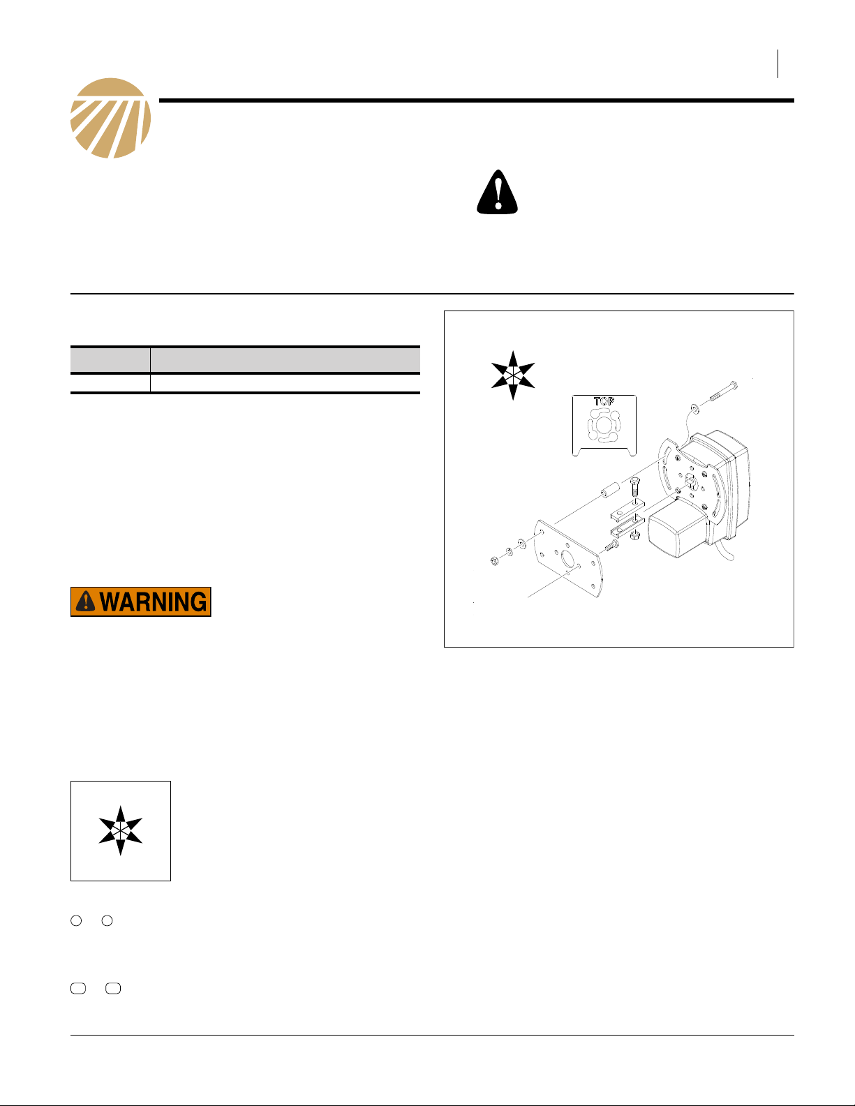
“Left” and “Right” are facing in the
direction of machine travel. An orienta-
R
tion rose in the line art illustrations
shows the directions of Left, Right,
Front, Back, Up, Down.
B
Figure 1
Actuator Field Kit
32495
© Copyright 2012 Printed 01/11/2012 401-809M
2 Great Plains Manufacturing, Inc. Actuator Field Kit
Remove Old Actuator
Refer to Figure 2
1. Unfold machine.
Note: In some cases, but not all, the machine must be in
unfold position to access the actuator.
Note: In some cases a ladder is needed to reach the
actuator.
2. Before removing the old actuator, mark the air box
mount bracket so that the new actuator can be
assembled with the same orientation angle as the
old actuator.
3. Remove 4 bolts attaching old actuator on air box
mount bracket.
4. Remove one bolt holding coupler shaft flats .
5. Undo weather pack.
1
12
12
Figure 2
Old Actuator
1
3/4in
32494
Null4:
Install New Actuator
Refer to Figure 3 and Figure 4
Safety Hazard:
Always wear protective equipment. Wear safety glasses and
gloves when using industrial tools.
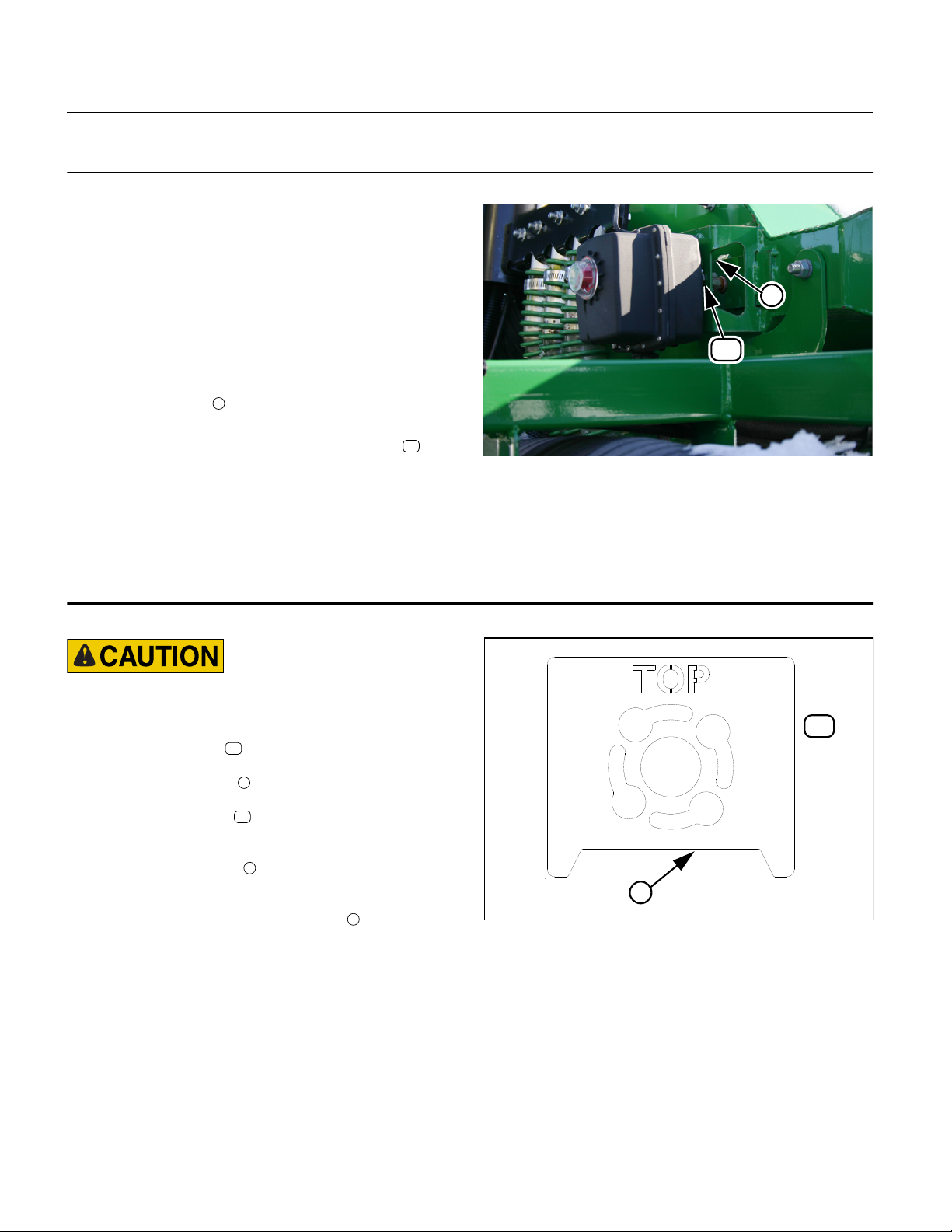
6. The new actuator will not fit correctly without
removing material from the bottom of the existing air
box actuator mount (see Figure 4).
Place the template supplied with the kit over the
actuator mount, lining up the slots on the template
with those on the mount and mark the area at the
bottom of the mount to be removed.
Use a die grinder or cutoff wheel and remove the
area from the bottom of the bracket .
16
3
15
3
3
3
Figure 3
Template
15
3/4in
34002
401-809M 01/11/2012
 Loading...