

Page 1
Operator’ s Manual
Model 2250
Air Drill Implement
Manufacturing, Inc.
www .g reatplainsmfg.com
Read the Operator’s manual entirely. When you see this symbol, the subsequent in-
!
structions andwarnings are serious- follow without exception. Your life and the lives of
others depend on it!
© Copyright 1997 Printed
5/11/2005
15075
Cover illustration may show optional equipment not supplied with standard unit.
160-192M
Page 2

Table of Contents
Table of Contents
Great Plains Mfg., Inc.
Important Safety Information . . . . . . . . . . . . . . . . . . 1
Safety Notations . . . . . . . . . . . . . . . . . . . . . . . . . . 1
Safety Rules . . . . . . . . . . . . . . . . . . . . . . . . . . . . . 1
Safety Labels. . . . . . . . . . . . . . . . . . . . . . . . . . . . . 3
Description of Unit . . . . . . . . . . . . . . . . . . . . . . . . . 9
Features include:. . . . . . . . . . . . . . . . . . . . . . . . . . 9
Section 3 Adjustments . . . . . . . . . . . . . . . . . . . . . . 33
Intended Usage . . . . . . . . . . . . . . . . . . . . . . . . . . . 9
Using This Manual. . . . . . . . . . . . . . . . . . . . . . . . . 9
Terminology: . . . . . . . . . . . . . . . . . . . . . . . . . . 9
Definitions: . . . . . . . . . . . . . . . . . . . . . . . . . . . 9
Owner Assistance . . . . . . . . . . . . . . . . . . . . . . . . . 9
Introduction . . . . . . . . . . . . . . . . . . . . . . . . . . . . . . . . 9
Section 1 Assembly and Setup. . . . . . . . . . . . . . . . 11
Pre-Assembly Checklist. . . . . . . . . . . . . . . . . . . . 11
General Description. . . . . . . . . . . . . . . . . . . . . . . 11
Shipping Information . . . . . . . . . . . . . . . . . . . 11
Implement Main Frame . . . . . . . . . . . . . . . . . . . . 11
Hydraulic Cylinder Mounting Locations . . . . . . . . 13
Dual Gauge Wheels. . . . . . . . . . . . . . . . . . . . . . . 13
Wing Lift Assist . . . . . . . . . . . . . . . . . . . . . . . . . . 13
Lift System
Hydraulic Hose Connections . . . . . . . . . . . . . . . . 14
Fold Cylinders . . . . . . . . . . . . . . . . . . . . . . . . . . . 14
Mounting the Cart Links. . . . . . . . . . . . . . . . . . . . 16
Attaching the Cart to the Implement . . . . . . . . . . 16
Section 4 Troubleshooting. . . . . . . . . . . . . . . . . . . 37
Section 5 Maintenance and Lubrication . . . . . . . . 39
Bleeding the Hydraulic Lifting System. . . . . . . . . 16
Pre-Fold Coulter Settings . . . . . . . . . . . . . . . . . . 18
Bleeding the Folding System. . . . . . . . . . . . . . . . 19
Side to Side Frame Leveling . . . . . . . . . . . . . . . . 19
Implement Frame Leveling . . . . . . . . . . . . . . 19
Distribution Towers and Hoses . . . . . . . . . . . . . . 20
2 1/2" Primary Distribution Hoses . . . . . . . . . . . . 21
1" Secondary Distribution Hoses. . . . . . . . . . . . . 26
Light Harness and Brackets. . . . . . . . . . . . . . . . . 28
Section 2 Operating Instructions . . . . . . . . . . . . . . 29
General Description. . . . . . . . . . . . . . . . . . . . . . . 29
Prestart Checklist: . . . . . . . . . . . . . . . . . . . . . . . . 29
Recommended Tractor Size . . . . . . . . . . . . . . . . 29
Recommended Minimum Tractor Size. . . . . . . . . 29
Safety Lights . . . . . . . . . . . . . . . . . . . . . . . . . . . . 29
Field Operations . . . . . . . . . . . . . . . . . . . . . . . . . 29
Section 6 Specifications and Capacities . . . . . . . 43
Implement Lifting System . . . . . . . . . . . . . . . . . . 30
Folding the Drill . . . . . . . . . . . . . . . . . . . . . . . . . . 30
Unfolding the Drill . . . . . . . . . . . . . . . . . . . . . . . . 31
Section 7 Appendix. . . . . . . . . . . . . . . . . . . . . . . . . 44
Opener Operation . . . . . . . . . . . . . . . . . . . . . . . . 31
© Copyright 1996 All rights Reserved
Great Plains Manufacturing, Inc. providesthis publication“as is” without warrantyof any kind, either expressed or implied. While every precaution has been taken in the preparation
of this manual, Great Plains Manufacturing,Inc. assumes no responsibility for errorsor omissions. Neither is anyliability assumed fordamages resulting from the use of the information contained herein. Great Plains Manufacturing, Inc. reservesthe right to revise and improve its products as it sees fit. This publication describes the state of this product at the
time of its publication, and may not reflect the product in the future.
The following are trademarks of Great Plains Mfg., Inc.: Application Systems, Ausherman, Land Pride, Great Plains
All other brands and product names are trademarks or registered trademarks of their respective holders.
Great Plains Manufacturing, IncorporatedTrademarks
Printed in the United States of America.
General Opener Operation. . . . . . . . . . . . . . 31
C-Shank Style Opener. . . . . . . . . . . . . . . . . 31
Floating Hoe Opener . . . . . . . . . . . . . . . . . . 31
Transporting . . . . . . . . . . . . . . . . . . . . . . . . . . . . 31
Parking . . . . . . . . . . . . . . . . . . . . . . . . . . . . . . . . 32
Setting the Seeding Depth
And Leveling Front to Rear. . . . . . . . . . . . . . . . . 33
Individual Opener Adjustments. . . . . . . . . . . . . . 33
C-Shank Style Openers . . . . . . . . . . . . . . . . 33
Floating Hoe Openers . . . . . . . . . . . . . . . . . 33
Shear Bolt and Spring Reset
Opener Depth. . . . . . . . . . . . . . . . . . . . . . . . 33
Shear Bolt and Spring Reset
Opener Down Pressure . . . . . . . . . . . . . . . . 34
Hoe Tip Angle . . . . . . . . . . . . . . . . . . . . . . . 34
Coulter Adjustments. . . . . . . . . . . . . . . . . . . . . . 35
Individual Coulter Depth Adjustments . . . . . 35
Coulter Spring Adjustments . . . . . . . . . . . . . 35
Fertilizer Tine Adjustments. . . . . . . . . . . . . . . . . 35
Dry Fertilizer Tine Depth Adjustments . . . . . 35
Electric Clutch Height Switch . . . . . . . . . . . . . . . 36
Maintenance. . . . . . . . . . . . . . . . . . . . . . . . . . . . 39
Storage. . . . . . . . . . . . . . . . . . . . . . . . . . . . . . . . 39
Lubrication . . . . . . . . . . . . . . . . . . . . . . . . . . . . . 39
Lift Assist and Gauge Wheel Pivots. . . . . . . 39
Press Wheel Pivot Bearings. . . . . . . . . . . . . 40
Cart Link Pivots . . . . . . . . . . . . . . . . . . . . . . 40
Castor Wheel Shafts . . . . . . . . . . . . . . . . . . 40
Press Wheel Gang Bearings . . . . . . . . . . . . 40
Press Wheel Screw Adjustment Thread . . . 41
Hinge Pivots. . . . . . . . . . . . . . . . . . . . . . . . . 41
Parallel Arm Pivots. . . . . . . . . . . . . . . . . . . . 41
Press Wheel Screw Adjustments. . . . . . . . . 41
Coulters . . . . . . . . . . . . . . . . . . . . . . . . . . . . 42
Floating Hoes. . . . . . . . . . . . . . . . . . . . . . . . 42
Wheel or Axle Bearings . . . . . . . . . . . . . . . . 42
Floating Hoe Option. . . . . . . . . . . . . . . . . . . 43
C-Shank Option . . . . . . . . . . . . . . . . . . . . . . 43
Tire Inflation Chart . . . . . . . . . . . . . . . . . . . . . . . 44
Torque Values Chart for Common Bolt Sizes. . . 44
Warranty. . . . . . . . . . . . . . . . . . . . . . . . . . . . . . . 45
Model 2250 Air Drill Implement 160-192M 5/11/05
Page 3

Great Plains Mfg., Inc.
Important Safety Information
Important Safety Information
For your safety and to develop a better understanding of
your equipment, thoroughly read the Operator’s Sections
of this manual before operation.
Safety Notations
The SAFETY ALERT SYMBOL indicates that there is a
potential hazard to personal safety involved and extra
safetyprecautions mustbe taken. When you see this symbol,bealert and carefully readthemessage that followsit.
In addition to design and configuration of equipment; hazard control and accident prevention are dependent upon
the awareness, concern, prudence and proper training of
personnel involved in the operation, transport, maintenance and storage of equipment.
Watch for the following Safety Notations throughout
your Operator’s Manual:
!
DANGER!
Indicates an imminently hazardous situation which, if not
avoided, will result in death or serious injury. This signal word
is limited to the most extreme situations.
!
WARNING!
Indicates a potentially hazardous situation which, if not avoided, could result in death or serious injury.
!
Prior To Operation
1. Do not stand between the cart and implement during hitching.
2. Do not operate without safety chain properly attached to
tractor.
3. Make sure hydraulic lines are attached to correct ports.
4. Handle and apply chemically treated seeds according to
manufacturer’s recommendations.
!
CAUTION!
Some illustrations in this manual may show shields or cover
panels removed for clarity. Never operate unit without all
shields and cover panels in place.
During Operation
1. Do not allow anyone to operate this machine who has not
been properly trained in its safe operation.
2. Do not let children operate the implement.
3. Never dismount from a moving tractor.
4. Put tractor in park, shut off engine, and remove key before
making any adjustments to the implement.
5. Do not leave the tractor or the implement unattended with
the engine running.
6. Never allow passengers
7. Never permit anyone to ride on or walk beside the implement.
8. Always fold and unfold implement SLOWLY and on level
ground.
9. Allow proper clearance both overhead and on the ground
when folding or unfolding.
!
CAUTION!
Indicates a potentially hazardous situation which, if not avoided, may result in minor or moderate injury. It may also be used
to alert against unsafe practices
!
Safety Rules
These rules and instructions
must be revie wed at least ann uall y
by all operators!
Most accidents are the result of negligence and carelessness, caused by failure of the operator to follow safety
precautions. Even though your implement is designed
with many built-in safety features, the following precautions are mandatory to prevent such accidents.
Make sure everyone that uses this machine has read the
Operator’sManual and understands how to operate it
safely.
This Operator’sManual is considered a part of the implement and should remain so when loaned or sold.
!
DANGER!
Contact with overhead power lines can cause severe electrical
burns or death from electrocution. Make sure there is enough
clearancebetween all airdrill components and overheadpower
lines. Do not fold or unfold implement near power lines.
Transporting
1. Be alert to traffic when crossing or operating near road-
ways. Always maintain complete control of the machine.
Know your state and local laws concerning highway safety
and regulations. Comply with these laws when transporting
machinery.
2. Do not exceed 20 mph when transporting. Transport only
with a farm tractor of sufficient size and horsepower. Refer
to Recommended Tractor Size under the “Operating In-
structions” section on page 29.
3. Be aware of any overhead or roadside obstructions when
transporting (i.e., power lines, bridges, fence rows, culverts, etc.).
4. Always make sure flashing lights, slow moving vehicle emblem, and reflectors are in place and visible prior to transporting the machine.
5. Use warning flags or approved warning lights when transporting at night or at other times of low visibility.
6. Always be aware that towing a large implement can signif-
5/11/05
Model 2250 Air Drill Implement 160-192M
1
Page 4

Important Safety Information
Great Plains Mfg., Inc.
icantly increase stopping times and distances.
7. Reduce speed when transporting over hills or steep slopes.
8. Use caution and reduce speed when transporting or operating with full seed bins.
9. Never transport without all transport and fold locks in
place. See Folding the Drill under the “Operating Instruc-
tions” on page 30.
After Operation
1. Detach and store implement in an area where children do
not play. Stabilize implement by using suitable supports and
wheel blocks.
2. Always store implement with all transport and fold locks in
place See Parking under the “Operating Instructions” on
page 32.
During Maintenance
1. Tire changing can be dangerous and should be performed
by trained personnel using the correct tools and equipment.
2. Do not re-inflate a tire that has been run flat or seriously
under inflated. Have it checked by qualified personnel.
3. When removing or installing wheels, use wheel handling
equipment adequate for the weight involved.
4. Do not grease or oil implement while it is in use.
5. Always unfold implement and have cylinder lock channels
in place when lubricating or maintaining implement. See
Unfolding the Drill under the “Operating Instructions”
section on page 31.
6. After repairing or adjusting, make sure all tools and loose
parts are removed from the implement before attempting to
operate it.
Agricultural Chemicals
1. Agricultural chemicals can be dangerous. Always select the
correct chemical for the job. Improper usage of fertilizers,
fungicides, herbicides, insecticides, and pesticides could
cause injury to all living things.
2. Always read instructions supplied by the manufacturers before opening chemical containers. Carefully read and follow instructions supplied by the chemical manufacturer
before each use.
3. Apply the same precautions when adjusting, servicing,
cleaning, or storing this implement as you would when putting chemicals into it.
4. Advise anyone who may come into contact with chemicals
of all safety precautions that should be observed.
5. Avoid inhaling smoke from any type of chemical fire.
6. Store or dispose of all unused chemicals and chemical containers as specified by the chemical manufacturer.
Model 2250 Air Drill Implement 160-192M 5/11/05
2
Page 5
Great Plains Mfg., Inc.
Important Safety Information
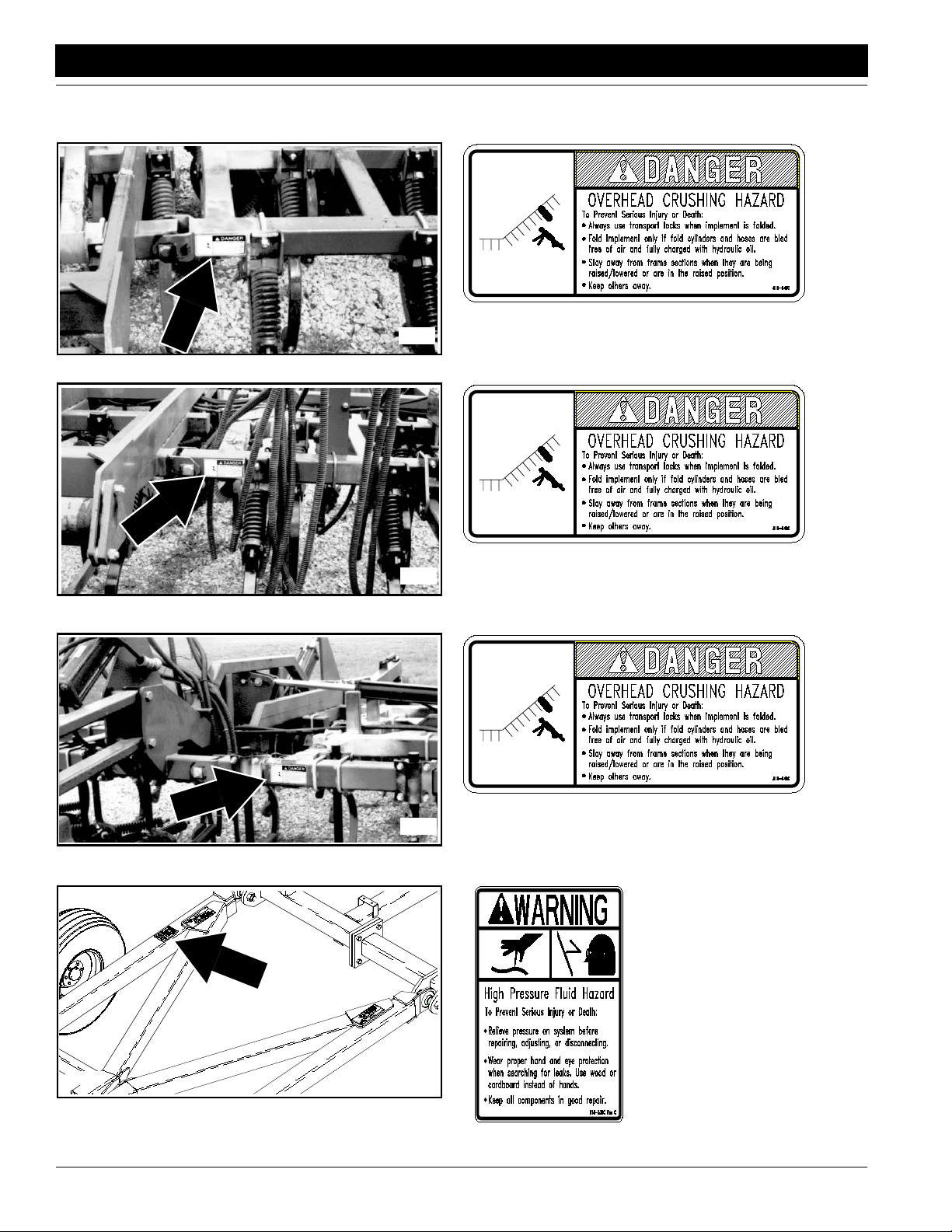
Safety Labels
Your implement comes equipped with all safety labels in place.
They were designed to help you safely operate your implement.
1. Read and follow label directions.
2. Keep all safety labels clean and legible.
3. Replace all damaged or missing labels.
4. Some new equipment installed during repair require safety
labels to be affixed to the replaced component as specified
15078
by the manufacturer. When ordering new components make
sure the correct safety labels are included in the request. To
order new labels go to your Great Plains dealer.
5. Refer to this section for proper label placement.
To install new labels:
a. Clean the area where the label is to be placed.
b. Peel backing from label. Press firmly on surface
being careful not to cause air bubbles under label.
818-055C
Slow Moving Vehicle Label
15098
15104
838-266C
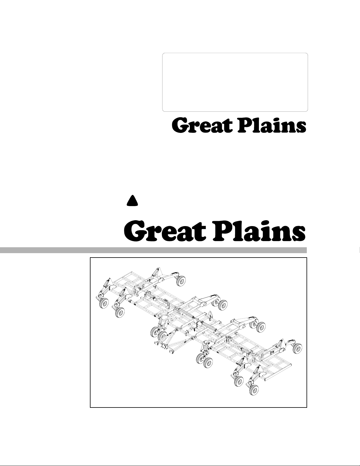
Red Reflector
Located on each lift as-
sist arm.
838-265C
Amber Reflector
5/11/05
Model 2250 Air Drill Implement 160-192M
3
Page 6
Important Safety Information
Great Plains Mfg., Inc.
838-265C
Amber Reflector
15100
838-265C
Amber Reflector
15101
15372
838-265C
Amber Reflector
15101
Model 2250 Air Drill Implement 160-192M 5/11/05
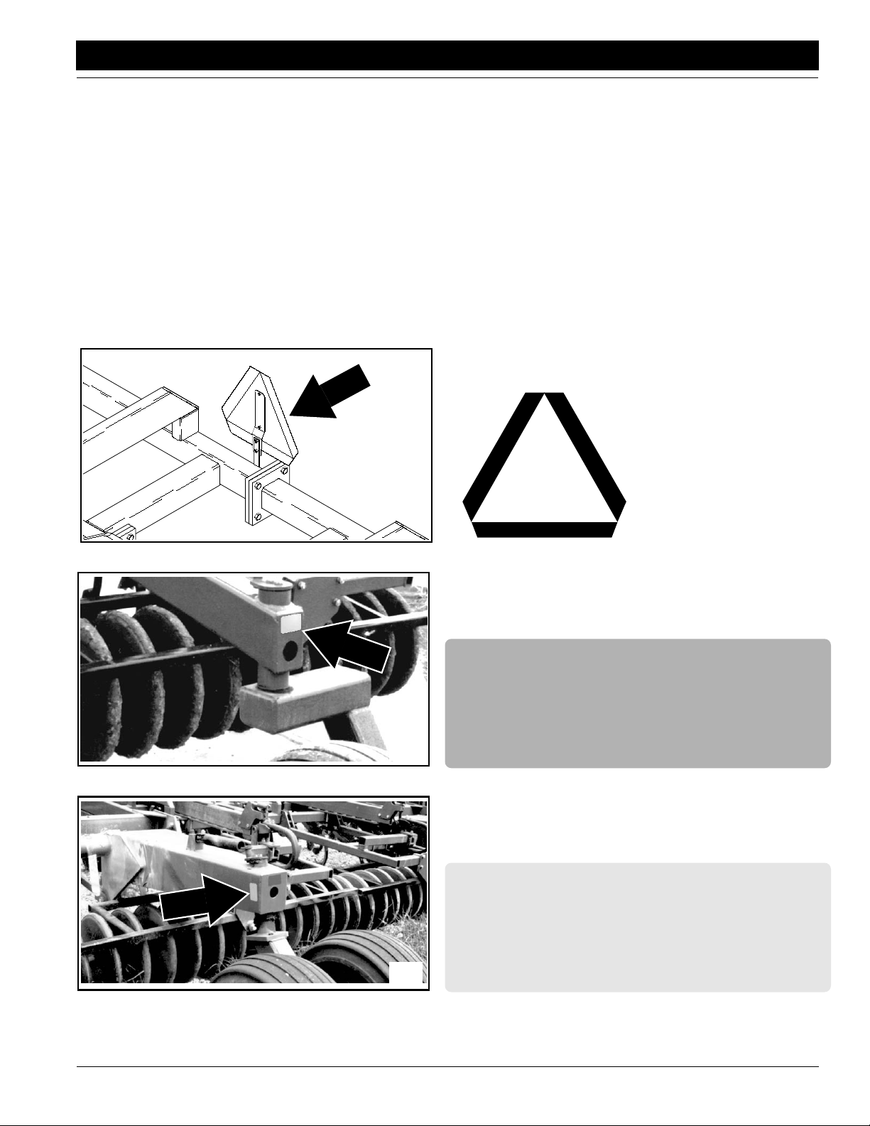
4
818-046C
Overhead Crushing Hazard
Page 7
Great Plains Mfg., Inc.
Important Safety Information
15102
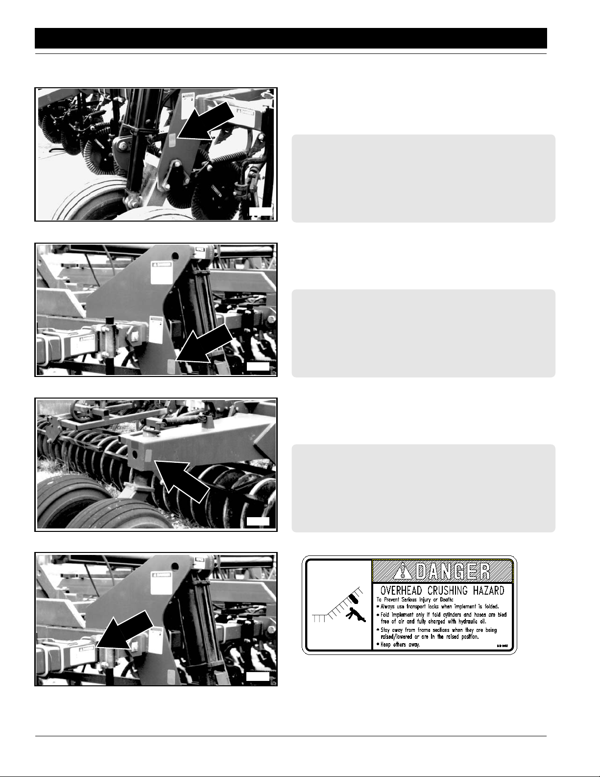
15105
818-046C
Overhead Crushing Hazard
818-046C
Overhead Crushing Hazard
15081
5/11/05
15086
818-046C
Overhead Crushing Hazard
818-046C
Overhead Crushing Hazard
Model 2250 Air Drill Implement 160-192M
5
Page 8
Important Safety Information
Great Plains Mfg., Inc.
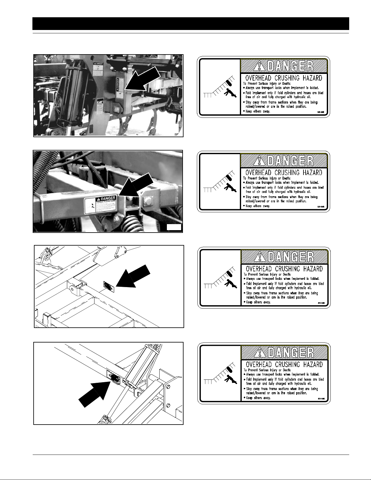
15370
15371
818-046C
Crushing Hazard
818-046C
Crushing Hazard
15505
818-046C
Crushing Hazard
15081
Model 2250 Air Drill Implement 160-192M 5/11/05
6
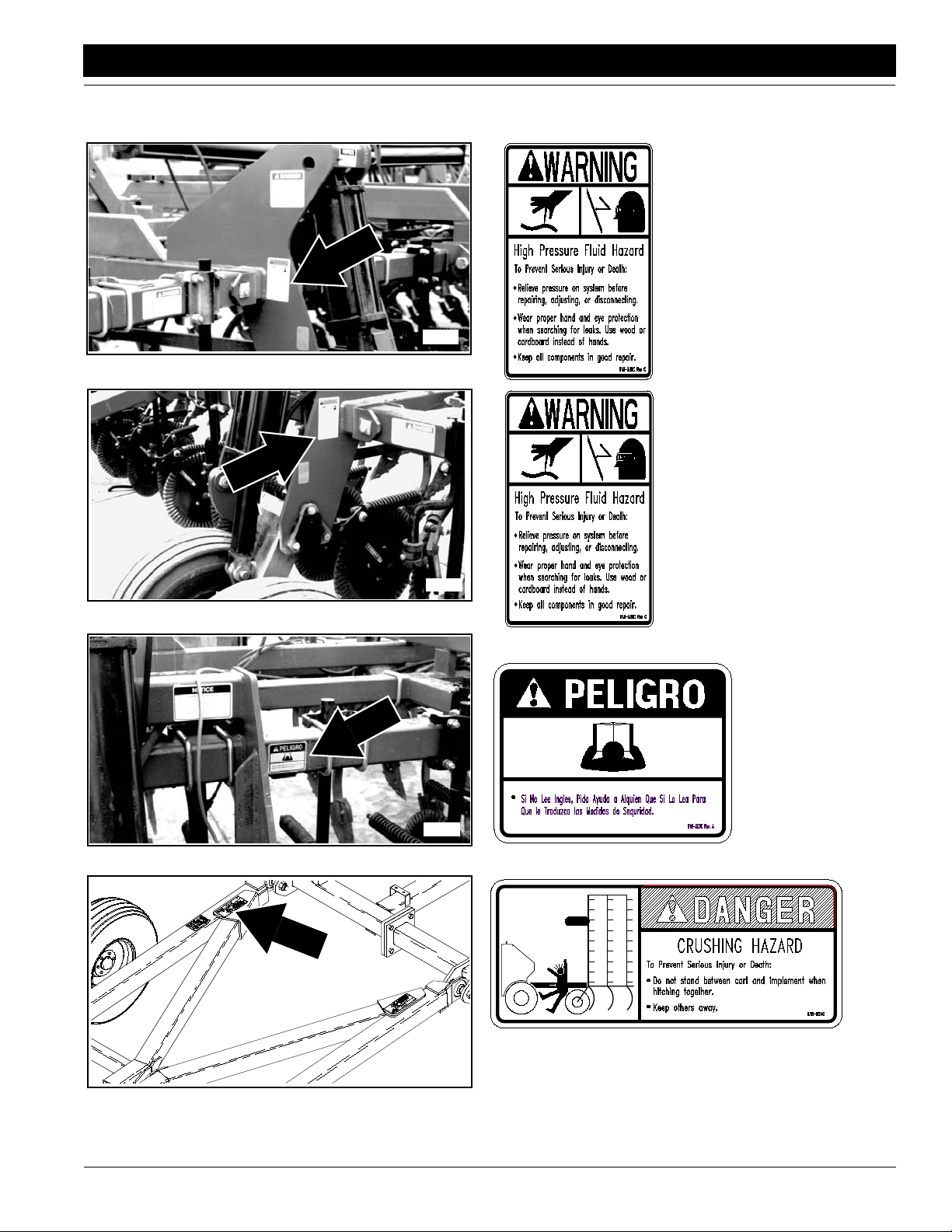
15088
818-339C
High Pressure Fluid
Page 9
Great Plains Mfg., Inc.
Important Safety Information
15101
15100
818-339C
High Pressure Fluid
818-339C
High Pressure Fluid
5/11/05
15106
15088
818-624C
Crushing Hazard
818-557C
Cannot Read English
Model 2250 Air Drill Implement 160-192M
7
Page 10
Important Safety Information
Great Plains Mfg., Inc.
15088
15101
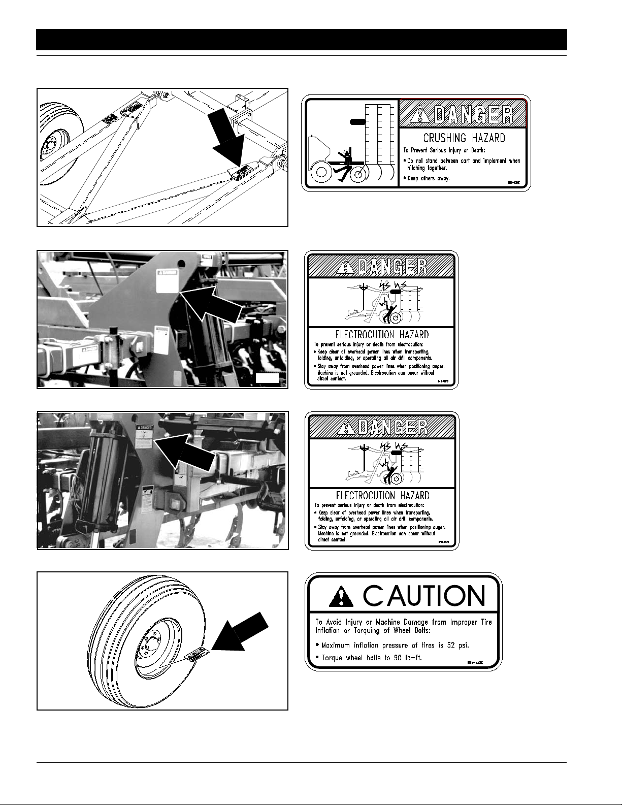
818-624C
Crushing Hazard
818-627C
Electrocution Hazard
15102
15597
Model 2250 Air Drill Implement 160-192M 5/11/05
8
818-752C
Improper Tire Inflation or Torquing
Electrocution Hazard
818-627C
Page 11

Great Plains Mfg., Inc.
Introduction
Introduction
Great Plains welcomes you to the growing family of new
product owners. This implement has been designed with
care and built by skilled workers using quality materials.
Proper assembly, maintenance, and safe operating practices will help you get years of satisfactory use from the
machine.
Description of Unit
The 45', 7" row spacing air drill implement is a tillage-type
seedingimplement designed to tow behind a Great Plains
airdrill cart.The implement is configuredwith75 hoe-type
openers spaced 7 inches apart. The implement can also
be equipped with coulters spaced on 14” centers that split
every two openers. The cart suppliespneumatically conveyedseed or fertilizer to the implement where it is distributed to each opener. Seed and fertilizer can be delivered
separately (double shoot) to either the opener or the
coulter.
Features include:
• Minimum 28” distance from frame to ground for trash
clearance.
• Three ranks of openers and one rank of coulters or
openers spread across all four ranks for greater trash
clearance.
• Coulters which can be used for cutting residue in front of
openers and can also be used to apply fertilizer.
• Integral-style hitch which simplifies backing and elimi-
nates side to side motion on hillsides.
• Easily adjustable electric clutch height switch to shut off
metering system during headland turns.
• Low maintenance seed distribution tower system.
• Single and double shoot capabilities.
• C-Shank or Floating Hoe opener options.
• Five press wheel options.
dealer the white copy and send the pink copy to Great
Plains. Keep your copy in the manual for use when corresponding with the dealer.
To order a new Operator or Parts Manual contact your authorized dealer or write to the address listed below in the
Owner Assistance paragraph. Include the model and serial numbers of your unit.
The information contained within this manual was current
at the time of printing. Some parts may change slightly to
assure you of the best performance.
Terminology:
"Right" or "Left" as used in this manual is determined by
facingthe direction the machine will travelwhile in use unless otherwise stated.
Definitions:
NOTE: A special point of information related to it’s
preceding topic. The author’s intention is that you
read and note this information before continuing.
IMPORTANT: Information, related to it’s proceeding topic
that the author feels would be of use.
Owner Assistance
If customer service or repair parts are required contact
your local Great Plains dealer. He has trained personnel,
repair parts, and the equipment needed to service your
implement.
These parts have been specially designed and should
only be replaced with genuine Great Plains parts.
Serial Number Plate
Referto the Figure 1 for the location of your serialnumber
plate.
Intended Usage
This machine is intended to be used primarily for seeding
small grains and legumes in conventional tillage or no-till
applications. When used in conjunction with a Great
Plains air drill cart, the implement will evenly distribute
seed and fertilizer to each opener or coulter at an even
depth thereby promoting consistent seed emergence.
Using This Manual
ThisOperator’sSection is designed to help familiarize you
with safety, assembly, operation, adjustments, troubleshooting, and maintenance. Read this manual and follow
the recommendations to help ensure safe and efficient
operation.
The warranty sheet should be filled out by the owner and
dealer at the time of purchase. After completion give the
5/11/05
Serial Number Plate Location
Figure 1
Forpromptservicealwaysusetheserial numberandmodel
Model 2250 Air Drill Implement 160-192M
15162
9
Page 12

Introduction
Great Plains Mfg., Inc.
numberwhenordering partsfrom your Great Plains dealer.
Be sure to include your serial and model numbers in correspondence also.
Your dealer wants you to be satisfied with your new machine. If for any reason you do not understand any part of
this manual or are not satisfied with the service received,
the following actions are suggested:
1. Discussthe matter with your dealership Service Manager make sure he is aware of any problems you may
haveand that he has had the opportunityto assist you.
2. If you are still not satisfied, seek out the Owner or
General Manager of the dealership, explain the problem and request assistance.
3. For further assistance write to:
Product Support
Great Plains Mfg. Inc., Service Department
P.O. Box 245
Assaria, Ks. 67416
Model 2250 Air Drill Implement 160-192M 5/11/05
10
Page 13

Great Plains Mfg., Inc.
Section 1 Assembly and Setup
Section 1 Assembly and Setup
The following information is general in nature and was
written to aid the operator in preparing the tractor and air
drill implement for use as well as to provide general operating procedures. The operator’s experience, familiarity
with the machine,and the followinginformation combined
should provide efficient drill operation and good working
habits.
Having all the parts and equipment readily at hand will
speed your assembly task and make the job as safe as
possible.
Pre-Assembly Checklist
Check Reference
All major frame components Operator’s
Fasteners and pins that were shipped with
the drill.
NOTE: If a pre-assembled part or fastener
is temporarily removed for assembly reasons, remember where it goes. Keep the
parts separated.
All working parts are moving freely, bolts
are tight and cotter pins are spread.
All grease fittings are in place and lubricated.
Safety labels are correctly located and legi-
pre-assemb
ble. Replace if damaged.
Get
Red and amber reflectors are correctly
located and visible when the drill is in the
transport position.
Inflate tires to specified air pressure. Tighten
wheel bolts to specified torque.
Have a minimum of 2 people at hand while
assembling the drill.
Have a fork lift or hoist along with chains
and safety stands that are sized for the job
ready for the assembly task.
ly chec
from
list
k
John
Operator’s
Operator’s
Section 5
.
P
page 39
ImportantSafety
Information
ImportantSafety
Information
Section 11
page 44
Operator’s
Operator’s
The air drill implement is shipped via flat bed truck. The
implement is not fully assembled.
Make sure the assembly area is level and free of obstructions (preferablyan open concrete area). Make sure the
assembly area is large enough for the assembled machine. Final assembled width of implement will be 45'.
Unload all equipment before beginning assembly. Do not
attempt any assembly work while the drill is onthe truck.
Separatestackedframes.Leaveshipping standsattached
to the bottom of each frame section.
Read and understand the previous section, “Important
Safety Information” beginning on page 1, before starting
assembly.
Implement Main Frame
!
DANGER!
Crushing hazard. You may be severely injured or killed by the
implement frames if they fall. Always support the implement
frames with jack stands or blocks before working on implement
raised off the ground.
!
WARNING!
Obeyall safety instructions from lifting equipment manufacturer.
Do not walk or place any part of the body under the raised sections. Be sure shipping stands ar e securely attached prior to lifting.Be sure lifting equipment has enough capacity to lift sections.
NOTE:Each stack of frame sections can weigh up to
8,000 pounds depending on opener, press wheel,
and coulter options.
General Description
This section covers the dealer’s requirements to assemble
the drill.
Tools Required:
• Fork lift or overhead hoist with 8000# capacity.
• Tractor of sufficient size and horsepower with remote hy-
draulics.Refer to the RecommendedTractorSizeportion
of the “Assembly and Setup” section on page 29.
• General hand tools.
• Jack stands or blocks and safety chain.
Shipping Information
NOTE:You will also need approximately20gallonsof
hydraulic oil to refill the tractor’s hydraulic reservoir
after initial bleeding and cycling of the hydraulic lift
and fold systems.
5/11/05
1. Remove the stacked implement sections fromthe
truck and placethem on the ground.
2. With all stacks securely on the ground, remove the u-
bolts from the bottom of the shipping stand on the
highestsectionssothatthe stand remains attached to
the upper section.
3. Carefully lift the section off of the stackand place it on
solid, levelground or concrete if available.
4. Repeat steps 2 and 3 with each section until all sec-
tions are separated and unstacked. Refer to for location of frame sections.
NOTE:Be sure that the pivot bushings are in place in
the pivot tubes before positioning sections.
Model 2250 Air Drill Implement 160-192M
11
Page 14
Section 1 Assembly and Setup
Great Plains Mfg., Inc.
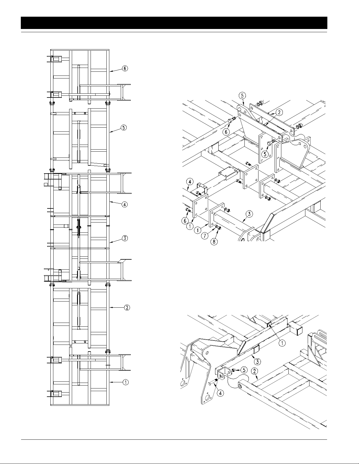
With the shipping stands still bolted to each frame section,
usethe hoist orforkliftto moveframesections three(#3)and
four(#4) to center of assembly area, refer to Figure 1-1 and
Figure 1-2. Alignflanges (#1) on each frame section and
bolt together using 3/4” x 2 3/4” bolts (#6), 3/4” lock washers (#7), and 3/4” hex nuts (#8). Attach a flex-limiter strap
(#2) to each side of cylinder lugs (#5) using a 1” x 3 1/2”
bolt (#6).
15379
15108
Frame Sections #3 and #4 Assembly
Figure 1-2
Refer to Figure 1-3:
Withtheshippingstands still bolted to each frame section,
moveframe section two (#2) so that the pivotbushingend
is aligned with the clevis end of frame section three (#3).
Be sure frame section two is not confused with frame section five. This can be avoided by making sure the fold
tubes (#1) are aligned before the frame sections are
joined.
Frame Locations
Figure 1-1
Model 2250 Air Drill Implement 160-192M 5/11/05
12
Frame Sections #2 & #3,
and #4 & #5 Assembly
Figure 1-3
15109
Page 15
Great Plains Mfg., Inc.
Section 1 Assembly and Setup
Connectframe section two(#2)toframesection three (#3)
usingtwo pivotclevisbolts(#4)and1” locknuts(#5). Make
sure the pivot clevis bolt heads are oriented to the outside
of the clevis and seated next to the welded key stock on
the clevis.This will preventrotation of the bolt in the clevis.
Repeat the above steps when joining frame section five to
frame section four.
Refer to Figure 1-4:
Moveframe section one(#1) so that the pivotbushing end
is aligned with the clevisend of frame section two (#2). Be
sure frame section one is not confused with frame section
six.Thiscan be avoidedbymaking sure the liftassistarms
(#3) are positioned in the same direction as that of frame
sections three and four.
Connect frame section one (#1) to frame section two (#2)
using two pivot clevis bolts (#4), and 1” nuts (#5). Make
sure the pivot clevis bolt heads are oriented to the outside
of the clevis and seated next to the welded key stock on
the clevis.
15110
Frame Sections #1 & #2, and #5 & #6 Assembly
Figure 1-4
Repeat the above steps when joining frame section 6 to
frame section 5.
The frame sections should now be assembled and still
supported by the shipping stands.
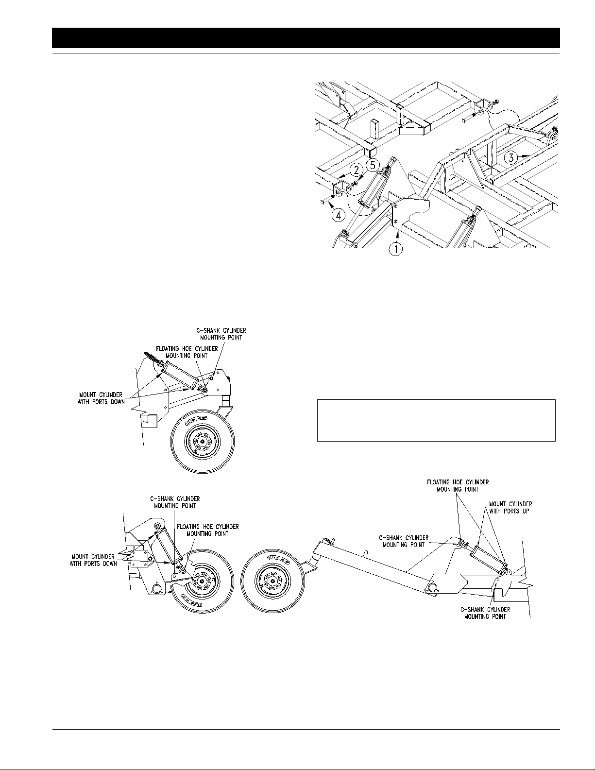
Hydraulic Cylinder Mounting Locations
Refer to Figure 1-5:
NOTE: Failure to correctly mount cylinders could
cause damage to the implement voiding the warranty.
5/11/05
Dual Gauge Wheels Wing Lift Assist
Hydraulic Cylinder Mounting Locations for Floating Hoe vs. Spring Shank
Figure 1-5
Model 2250 Air Drill Implement 160-192M
15149
13
Page 16

Section 1 Assembly and Setup
Great Plains Mfg., Inc.
Lift System
Hydraulic Hose Connections
NOTE: The SAE O-Ring and JIC 37˚ flare type hose
connections do not require sealant for reconnecting.
They do not require high torque for a good seal.
Uncoil the hoses from the first and the sixth frame sectionsand route them on the frame as showninFigure1-6.
The hoses from the rod end of the outer-most wing cylinders will connect to the elbows on the flow divider on the
center frame. The hoses from the base end of the wing
rear lift assist cylinders will attach to the rod end of the
master cylinders on the center section. Secure the hoses
to the frame with the 22”long cable ties provided. Avoid
routing the hoses where they could get pinched or worn
fromfolding,unfolding,raising, orloweringthe implement.
Do not let the hose rub on sharp edges and make sure
there is enough slack for down flex of the wing sections.
Lifting Hydraulics
Donottry to raiseorlowerimplement until circuit is bled of
air.Referto theBleedingtheHydraulic LiftingSystem,this
section starting on page 16.
Fold Cylinders
!
DANGER!
The folding cylinders must be bled free of air and implement
should be hooked to cart and tractor before attempting to fold
implement, otherwise severe property damage and bodily damage or death could result.
Positionthe main and outer fold cylinders with base ends
towardthe center of the drill. Pin the base ends to the fold
cylinderlugs. Secure thepinwiththeprovided clip,refer to
Figure 1-7. Leave rod end unhooked and block up in the
air so that the rod will not come into contact with any object when extended.Do not connect rod end until after air
is bled from fold circuit.
Hydraulic Hose Sizes
Item Part Number I.D. Length
1 811-054C 1/2" 97"
2 811-537C 1/2" 100"
3 811-541C 1/2" 256"
4 811-539C 1/2" 318"
5 811-437C 1/2" 90"
6 811-617C 1/2" 140"
7 811-538C 1/2" 288"
8 811-573C 1/2" 126"
Lift Cylinders
Item Part Number Bore
9 810-124C 4"
10 810-221C 4.25"
11 810-218C 4.5"
12 810-287C 4.75"
Lifting Hydraulics
Figure 1-6
Model 2250 Air Drill Implement 160-192M 5/11/05
14
15151
Page 17

Great Plains Mfg., Inc.
Section 1 Assembly and Setup
15111
Folding Hydraulics
Folding Hydraulics
Hydraulic Hose Sizes
Hydraulic Hose Sizes
Item Part Number I.D. Length
Item Part Number I.D. Length
1 811-558C 3/8" 85"
1 811-553C 3/8" 85"
2 811-556C 3/8" 85"
2 811-556C 3/8" 85"
3 811-555C 3/8" 55"
3 811-555C 3/8" 55"
4 811-557C 3/8" 108"
4 811-557C 3/8" 108"
5 811-237C 3/8" 174"
5 811-237C 3/8" 174"
6 811-583C 3/8" 158"
6 811-583C 3/8" 158"
9 811-630C 3/8” 44”
9 811-630C 3/8” 44”
Hydraulic Cylinders
Installing Fold System
Figure 1-7
Refer to Figure 1-8:
Installhydraulichoses. Note the hose lengths and be sure
to use the correct length hose in each location. Start with
the longest hose and work to the shortest.
Be sure to use the provided cable ties to help route the hydraulichoses so that they willnotgetpinchedorwornfrom
folding, unfolding, raising, or lowering the implement. Do
not let the hoses rub on sharpedges and make sure there
is enough slack for down-flex.
NOTE: The SAE O-Ring and JIC 37˚ flare type hose
connections do not require sealant for reconnecting.
They do not require high torque for a good seal.
7 810-292C 5" 7
8 810-309C 4" 8
Fittings & Misc.
Item Description
10 TEE 3/4 FJIC 3/4 MJIC 3/4 MJIC
11 ELBOW 3/4 MJIC 3/4 MOR
12 1” FOLD CYLINDER PIN
13 1” FLA T WASHER
14 3/16 X 1 3/4 COTTER PIN
15 1 1/4 CLEVIS PIN
16 TEE 3/4 MJIC 3/4 MOR 3/4 MJIC
17 1 1/4 FOLD CYLINDER PIN
18 1 1/4” FLA T WASHER
19 3/16 X 2 COTTER PIN
5/11/05
Folding Hydraulics
Figure 1-8
Model 2250 Air Drill Implement 160-192M
15150
15
Page 18

Section 1 Assembly and Setup
Mounting the Cart Links
Refer to Figure 1-9:
1. Bolttheoutside cartlink mounts (#1) to the backofthe
cart using the 3/4” x 2 1/2” bolts (#2), 3/4” lock washers (#3), and nuts (#4).
2. The center cartlink mount (#5) should be attached so
thatitisexactly centered betweenthetwooutsidecart
link mounts. Use the 3/4” x 8 1/32” x7 3/4” u-bolts
(#6), 3/4” lock washers (#3), and nuts (#4).
3. Attach the cart links (#7) to the mounts using 8 1/2”
(#8) and 14 1/2” (#9) cart link pins. Use 5/16” x 2 1/4”
bolt (#10) and 5/16” lock nut (#11) to secure the cart
link pins.
15122
Great Plains Mfg., Inc.
15123
Attaching Cart to Implement
Figure 1-10
2. Attach the light harnesslead on the implement to the
light harnesslead on the cart.If the light harnessand
brackets have not been assembled refer to Light Har-
ness and Brackets on page 28 for assembly instructions. Also connect the electric clutch switch lead to
the lead on the back of the cart.
3. Connect the two hoses for the fold circuit to the quick
couplers designated as the fold outlets on the cart.
4. Connect the two hoses for the lift circuit to the quick
couplers designated as the lift outlets on the cart.
Cart Link Assembly
Figure 1-9
Attaching the Cart to the Implement
!
WARNING!
You may be severely injured or killed by being crushed between
the tractor and cart or between the cart and implement. Do not
stand or place any part of your body between the cart and implement while hooking up the implement.
Refer to Figure 1-10:
1. With cart links tied up, slowly back cart towards the
center of the implement. When cart link ball swivels
(#1) are between and aligned with cartlink implement
lug (#2), pin link to lugs using 1 1/4” x 8” bolt (#3),
1 1/4” lock washer (#4), and nut (#5).
NOTE: When all connections have been made, carefully check all lines to make sure none will be damaged when the implement is operated. Re-route the
lines or use cable ties to keep them in a safe place.
Bleeding the Hydraulic Lifting System
The implement lifting system is equipped with rephasing
type hydraulic cylinders that require a special procedure
forbleedingairfromthehydrauliccircuits. Readandfollow
the procedure carefully. The rephasing type cylinders will
not function properly with air in the hydraulic circuit. This
will cause uneven seeding depth across the implement.
!
WARNING!
Seriousinjury or deathcould resultfromescaping high pressure
hydraulicfluid. Use paper or cardboard,NOTBODY PARTS, to
check for suspected leaks.
Model 2250 Air Drill Implement 160-192M 5/11/05
16
Page 19

Great Plains Mfg., Inc.
Section 1 Assembly and Setup
!
WARNING!
Before attempting to hydraulically lift the implement, air drill
cart must be attached to the implement and to a tractor of sufficient size. Failure to do so could result in severe equipment
damage and bodily injury or death.
NOTE: Check the hydraulic fluid level in the tractor
reservoir and fill to the proper level. Add fluid to the
system as needed. A low reservoir level may draw air
back into the system and cause jerky or uneven cylinder movement. During initial cycling of new hydraulic cylinders, approximately8 3/4 gallons of oil will be
used to fill the new cylinders.
1. Make sure implement frame sections are supported
by jack stands or blocks.
2. With the frame blocked and supported, unpin the rod
endof the gauge wheel andlift assist wheel cylinders.
Pivot the cylinders up and wire or otherwise safely
support the rod end port higher than the base end
port, refer to Figure 1-11. The center dual gauge
wheel cylinders may have to be removed from the
frame so that they can be oriented with therod end
higher than the base end.
ed, hold the remote leveron for one minute.Check all
hydraulic hoses, cylinders, and fittings for leaks.
4. Retract the cylinder rods. Extend the rods again and
hold the remote leveron for one more minute. Repeat
this step two more times tocompletely bleed the system.Ifthe gauge wheel levelingadjustments aretobe
made, see Side to Side Frame Leveling, this section,
on page 19. Leave the cylinders unpinned and the implement frame supported. Again, check all hydraulic
hoses, cylinders, and fittings for leaks.
5. Recheck the tractor hydraulic reservoir and fill to the
proper level.
6. Repin all cylinders. Be sure implement is hooked to
cart and tractor. See Attaching the Cart to the Imple-
ment, this section, on page 16.
7. Slowlyextendcylinders until all cylinder rods are completely extended.
8. Place cylinder lock channels on the front center dual
gauge wheel cylinder rods on both front dual gauge
wheels, see Figure 1-12.
14124
Bleeding Lift Hydraulic System
Figure 1-11
3. With the tractor engine at idlespeed, move the hydraulic remote lever so that hydraulic fluid is moved
into the lifting circuit. When the outboard cylinders on
both sides of the implement have completely extend-
5/11/05
15125
Cylinder Lock Channels in Place
Figure 1-12
9. If this is the first time the implement has been raised,
the shipping stands can now be removed. Make sure
cylinder lock channels are in place and implement
frame sections are sufficiently blocked up before attempting to remove shipping stands.
!
WARNING!
You may be severely injured or killed by being crushed from a
falling implement. Always have gauge wheel cylinder lock
channels in place and frame sufficiently blocked up when working on or around the implement.
Model 2250 Air Drill Implement 160-192M
17
Page 20

Section 1 Assembly and Setup
Pre-Fold Coulter Settings
IMPORTANT: Failure to understand the following instructions may result in equipment damage. Please read instructions and perform the steps required before
attempting to fold the implement for the first time.
Ifyourimplement comes equipped with coulters, you must
make additional adjustments before folding your implement for the first time. In order to ship yourimplement in a
more compact and efficient manner,the coulters were assembled in a raised position. This leaves the coulter
shanks extended far above the frame tube to which they
are mounted. If folding the implement is attempted while
the coulter shanks are extended in this manner, the top of
the shanks may bind at pivot points and equipment damage may result.
To avoid potential damage, coulters adjacent to fold pivot
pointsshould be adjusted so their shankextendsanallowable distance above the frame tube (see coulter adjustmentsinSection3ofyouroperator’smanual).Figure1-13
shows an example of an adjusted coulter.
Great Plains Mfg., Inc.
Coulter Shank Height
Figure 1-13
15274
Figure1-14 showswhichcoulters needtobeadjusted before
folding and how much their shanks may extend above the
frame tubes. All other coulters may be left in their shipping
positions if desired until field adjustments are necessary.
The coulter shanks sent with your unit maybe longer than
necessaryforyourapplication.The shanksweredesigned
to work with a variety of hoe boot lengths and operator
preferences.Atsome normaloperatingdepths, thecoulter
shank may extend too far above the frame tube. If this occurs,the top of the coulter shank may be trimmed or cut so
that the implement may fold without interference.
15240
Model 2250 Air Drill Implement 160-192M 5/11/05
18
Pre-Fold Coulter Shank Adjustments
Figure 1-14
Page 21

Great Plains Mfg., Inc.
Section 1 Assembly and Setup
Bleeding the Folding System
!
DANGER!
The folding cylinders must be bled free of air and implement
should be hooked to cart and tractor before attempting to fold
implement, otherwise severe property damage and bodily damage or death could result.
NOTE: Check the hydraulic fluid level in the tractor
reservoir and fill to the proper level. Add fluid to the
system as needed. A low reservoir level may draw air
back into the system and cause jerky or uneven cylinder movement. During initial cycling of new hydraulic cylinders, approximately 9.5 gallons of oil will be
used to fill the new cylinders.
1. Unpin the rod end of the fold cylinders and block up,
wire, or otherwise safely support the cylinders so that
when extended the rod end will not contact any objects.
2. Cycle the cylinders completely in and out a minimum
of three times to purge all air from the fold system. Inspect all hoses, cylinders, and fittings for hydraulic oil
leaks.
ment. Periodic frame leveling should not be necessary.
You may, however, field check the levelness of the implement by laying a straight edge across the top of at least
two members of a frame section and measuring the distance from the bottom of the straight edge to the center of
the gauge wheel axle.By comparing this measurement to
the measurements taken from other frame sections and
gauge wheels, an indication of levelnesscan be obtained.
If levelingis necessary, follow the instructions listed.
Implement Frame Leveling
1. Thegauge wheel hydrauliccircuitshould be bledofair
and full of oil, see Bleeding the Hydraulic Lifting Sys-
tem, this section, page 16.
2. Hydraulically lower the entire implement frame. The
frame should then be jacked up and supported, see
Bleeding the Hydraulic Lifting System,this section,
page 16.
3. Retract the lift cylinders fully. Because the front dual
gaugewheelsonthe implement frames three and four
are non-adjustable, all adjustments will be made with
these as a reference.A referencemeasurement must
be taken by laying a straight edge across the top of at
leasttwotubes on the implement frame and takea reference measurement from the bottom of the straight
edgeto the center of one dual gauge wheel axle, refer
to Figure 1-15.
!
WARNING!
Seriousinjury or deathcould resultfromescaping high pressure
hydraulicfluid. Use paper or cardboard,NOTBODY PARTS, to
check for suspected leaks.
3. Fullyextendthe cylinders torepinthe rod ends in their
respective slots.
NOTE:If cylinders on left or right side will not extend,
release the tractor hydraulic lever momentarily, reverse the lever, and then tryagain. This switches the
sequence valve used to unfold one side at a time
!
CAUTION!
Never fold implement unless gauge wheel cylinder lock channels are installed.
4. Recheckthe tractor hydraulic reservoirlevel and fill to
the proper level.
5. Slowlyfoldand unfold implement. Checkforhydraulic
leaks. Be aware of any pinch points that might damage or cause accelerated wear on hydraulic hoses.
Side to Side Frame Leveling
Equal seeding depth across the implement can only be
maintained if all frame sections are level.Leveling adjustments should be done during initial setup of the imple-
15126
Frame Leveling Measurement
Figure 1-15
4. Move the straight edge to the four castored gauge
wheels on sections one and six. Removethe cylinder
pins from the base ends of the hydraulic cylinders on
the castored gauge wheels. Block or support the
gauge wheels so that the measurement from the bottom of the straight edge tothe center of the gauge
wheelaxle is the same asthereferencemeasurement
takenon the dual gaugewheelsonsectionsthreeand
four. Loosen the jam nuts on the eye-bolts that the
base of the cylinders were fastened to and screw the
eye-boltsin or out until they can be pinnedto the base
endofthehydrauliccylinders.Securetheeye-boltsby
tightening the jam nuts, refer to Figure 1-16.
5/11/05
Model 2250 Air Drill Implement 160-192M
19
Page 22

Section 1 Assembly and Setup
Frame Leveling Measurement
Figure 1-16
Great Plains Mfg., Inc.
Distribution Towers and Hoses
NOTE:For best results, distribution towers should be
mounted as vertically as possible. A tower that leans
significantly to one side may cause uneven distribution, particularly when operating on hillsides.
Referto Figure 1-19 fortower mounting locations. Choose
implement configuration to determine tower placement.
1. Referto Figure1-17, install a tower supportbracketat
each location using the 1/2” u-bolt (#1), 1/2” lock
washers (#2), and 1/2” nuts (#3)
Mounting Tower
Figure 1-17
15207
2. Positiona tower on the bracketand secure with 2 1/2”
x 2 1/2” u-bolts. The bottom of the lower round plate
should be approximately 31 1/2 inches above the
frame members. The tower should be turned so that
inlet tube is pointed toward the center of the implement. The center tower inlet should face the front of
the implement, see Figure 1-18.
14546
Model 2250 Air Drill Implement 160-192M 5/11/05
20
Tower Positioning
Figure 1-18
14499
Page 23

Great Plains Mfg., Inc.
Section 1 Assembly and Setup
NOTE: Towers must be located so that there is no interference when wings are folded or unfolded. After
towers have been installed and before any seed hoses are installed, slowly fold the implement while
watching to be sure there are no interferences. Do
not stand under a wing while it is being folded or unfolded! If towers interfere with any other part of the
implement, completely unfold the implement and reposition the tower. Repeat these steps until implement folds without tower interference.
2 1/2" Primary Distribution Hoses
Chooseimplementconfigurationtodetermine correct hose
routing.
1. Start with center tower(s). Route hose as shown in
Figure 1-21. Slide hose at least two inches onto tower
inlet (slide clamp over the end of hose first).
2. Allowenoughhose so that implementraising,lowering,
folding, and unfolding will not pinch or bind the hose.
3. Using a hacksaw, cut hose so that it will slide at least
twoinches on to meter outlet or up to end of outlet flare.
NOTE: Each tower should be connected to its corresponding outlet at the back of the cart. For example,
the center tower should be connected to the center
outlet on the meter box, the far right hand tower
should be connected to the far right hand outlet on
the meter box, etc.
4. When using double shoot towers, be sure to connect
thetower hoses totheappropriateoutletattheback of
thecart(refertohoseinstallationprocedure in the cart
manual). Slide clamp over hose end then slide hose
onto meter outlet. Install the clamp so it will not interfere with other hoses, clamps, or meter door latch
handles.
5. Repeat the above procedure on the remaining towers
working from the center towers toward the outside.
6. Secureall hoses to the frameusingthe provided cable
ties. Be sure hoses will not be damaged by drill operation.
5/11/05
Model 2250 Air Drill Implement 160-192M
21
Page 24

Section 1 Assembly and Setup
Great Plains Mfg., Inc.
1513115130
Single Shoot Tower Mounting Locations
Figure 1-19
Model 2250 Air Drill Implement 160-192M 5/11/05
22
Page 25

Great Plains Mfg., Inc.
Section 1 Assembly and Setup
5/11/05
15132
Double Shoot Tower Mounting Locations
Figure 1-20
Model 2250 Air Drill Implement 160-192M
15133
23
Page 26

Section 1 Assembly and Setup
Great Plains Mfg., Inc.
15134
Single Shoot
15135
Double Shoot Coulters
3 Rank Seed Hose Routings
Figure 1-21
Model 2250 Air Drill Implement 160-192M 5/11/05
24
Page 27

Great Plains Mfg., Inc.
Section 1 Assembly and Setup
15136
Single Shoot
15137
5/11/05
Double Shoot
4 Rank Seed Hose Routings
Figure 1-22
Model 2250 Air Drill Implement 160-192M
25
Page 28

Section 1 Assembly and Setup
Great Plains Mfg., Inc.
1" Secondary Distribution Hoses
NOTE: Seed hoses must be routed to prevent them
from rubbing on sharp edges or being damaged
when the implement is raised, lowered, folded, or unfolded. Hoses must be pushed fully into distribution
tower ports until they are seated against the stop.
With the implement configuration in mind, refer to the appropriate hose routing illustration for the correct assembly
of hoses, Figure 1-21 and Figure 1-22.
1. Loosen bolts holding tower halves together, refer to
Figure 1-23.
Do not remove bolts.
3. To avoid serious injury or death from crushing, make
sure cylinder lockchannels are in place, implement is
sufficiently blockedup, and the tractor is shut off with
the key removed before attempting to route hoses to
openers.
Forfloating hoe openers, slide the clamp overthe end
of the hose approximately 6”. Put the end of the hose
in the seed tube approximately 6”. Hook the clamp
ends in the holes at the top of the seed tube,
see Figure 1-24.
14449
Tower Assembly
Figure 1-23
2. Attach the end of the hose to the opener (or coulter
fertilizer tube).
!
DANGER!
To avoid serious injury or death from crushing, make sure cylinder locks channels are in place, implement is sufficiently
blocked up, and tractor is shut off with the key removed before
attempting to route hoses to openers.
Model 2250 Air Drill Implement 160-192M 5/11/05
26
For coulters with fertilizer attachments, Figure 1-25, attach
seedbrake(#1)tocoulter fertilizer tube (#2) using provided
hoseclamp (#3). Make sure plastic tube (#4) is placed over
fertilizer tube. Connect 1” seed hose (#5) to other end of
seed brake using hose clamp (#3).
Floating Hoe Hose Attachment
Figure 1-24
14563
Page 29

Great Plains Mfg., Inc.
Section 1 Assembly and Setup
Coulter Fertilizer Assembly and Hose Attachment
Figure 1-25
For all other openers, refer to manufacturer’ sdirections for
connecting the seed hose.
4. Route the hose to the tower outlet. Allow just enough
slack for down flex of wings. Be sure to use outlet as
shown in Figure 1-21 and Figure 1-22.
5. Allow2 1/4” of hose toextendpast the edge of the tow-
er.Cut off hose as smoothly and squarely as possible
to allow a good fit in the tower.
6. Push the end of the hose into the port until it contacts
the stop, refer to Figure 1-23. This should require approximately 2 1/4” of hose.
7. Repeat steps1through6forall 1” hoses on each tower.
15157
8. When all hoses are installed on a tower,tighten the
bolts holding the halves together.
NOTE:The tower bolts areequipped with nylock nuts
and should not be over-tightened. Tighten the bolts
only until the hose is held securely against being
blown out. Do not bend tower plates.
9. Checkall hoses tobesurethatthey are notrubbingon
sharp edges and will not be damaged when the drill is
raised, lowered, folded, or unfolded. Re-route if necessary to prevent damage.
5/11/05
Model 2250 Air Drill Implement 160-192M
27
Page 30

Section 1 Assembly and Setup
Great Plains Mfg., Inc.
Light Harness and Brackets
Refer to Figure 1-26:
Attach the left (#1) and right (#2) side light brackets to the
left and right center section lift assist arms of the implement. Use the 3/4 x 3” bolts (#3) to secure them to the outer lift assist pivot bearings. Install the left (#4) and right
(#5) ag lights to the brackets using the 1/4 x 1 1/4” bolts
(#6). The lights should be installed with the red lenses to
the inside and facing the rear.Attach the light harness “Y”
connector(#9)totheterminal at the back of the cart(#10).
Route the wires along the frame members back to the
lights and plug in.
NOTE: The lead with the green wire goes to the right
sidelights,the lead with the yellow wire goes to theleft
side.
Securethe wire in place using thecableties (#11). Coil the
excess wire and cable tie it securely to the implement
frame.
Light Package Assembly
Figure 1-26
Model 2250 Air Drill Implement 160-192M 5/11/05
28
15159
Page 31

Great Plains Mfg., Inc.
Section 2 Operating Instructions
Section 2 Operating Instructions
General Description
This unit is a tillage-type seeding implement that can be
usedin both conventionalandno-till seeding applications.
It is designed to be used in conjunction with and towed behind a Great Plains air drill cart. Thecart supplies pneumatically conveyed seed or fertilizer through five or ten
2 1/2” primary hoses. Each 2 1/2” hose is connected to a
distribution tower where the seed or fertilizer is evenlydistributedandcarried by air and gravitythrough a 1” secondary hose to each opener or coulter. The implement frame
acceptstwotypes of openers: a floating hoeopener or a cshank-style opener. The openers, configured in a 7” row
spacing,can be mounted across four ranks 28” apart.The
openerscan also beplacedona 7” rowspacingacross the
rear three ranks 28” apart thereby allowing the use of
coulters on the front rank. The coulters are placed so that
they run inbetween every two rows (14” apart). The
coulters are used to cut through residue and can be
equipped to apply dry fertilizer.
Seeding depth is controlled by front gauge wheel and
press wheel gang height. Coulter depth can be adjusted
individually.
The implement is equipped with an electricclutch switch to
stop and startmetering at the cartwhen the implement is
raised and lowered. The switch is adjustable so that the
height at which metering is stopped or started can be varied.
Prestart Checklist:
• Lubricate the implement as indicated in the Lubrication
portion of the “Maintenance and Lubrication” section
starting on page 39.
• Check all tires for proper inflation. See the Tire Inflation
Chart in the “Appendix” section on page 44.
• Perform all beginning of season and daily service items
discussed in the “Maintenance and Lubrication” section starting on page 39.
• Check the implement for worn or damaged parts and re-
pair or replace them before going to the field.
• All nuts, bolts, and screws should be checked. Refer to
the Torque Value Chart in the “Appendix” section on
page 44.
Recommended Tractor Size
NOTE: The tractor must be of adequate size to pull
the drill. When determining size of the tractor, soil
type, terrain, opener type, and tillage practices must
be considered.
Recommended Minimum Tractor Size
Standard openers and coulters - 240 HP
Double shoot openers - 300 HP
!
CAUTION!
The tractor or towing vehicle must have adequate unladen mass
to controlthe drill when towing. Do not exceed 20 miles per hour.
Minimum towing vehicle weight - loaded drill:
up to 20 mph maximum - 45,000 lbs.
up to 10 mph maximum - 22,000 lbs.
Minimum towing vehicle weight - empty drill:
up to 20 mph maximum - 28,000 lbs.
up to 10 mph maximum - 14,000 lbs.
NOTE: The tractor must have at least three sets of
hydraulic outlets and be capable of supplying 15-30
gallons per minute at 2000 psi.
Safety Lights
The light package your drill comes equipped with requires
that your tractor be wired for the standard 7-pin electrical
connector which will work with the tractor’s flashers and
signals.The harness from the air drill cart should be ready
to plug into the connector.
If your tractor is not equipped with this connector, please
consult your dealer for installation to the tractor manufacturer’s specifications.
Field Operations
1. Be sure that all tires are properly inflated as indicated
in the Tire Inflation Chart in the “Appendix” section
on page 44.
2. Be sure that all hoses are connected and clear of foreign material. Make sure openers are not plugged.
3. Neverback up with the openers in the ground. Do not
turn sharply with openers in the ground, doing so will
causeopeners to plug and couldcausedamagetothe
implement.
4. Make sure that nobody is in the way of the drill before
moving. Do not allow anyone to ride on the drill.
5. Follow all cart field operation instructions as found in
the cart operator’s manual.
6. Witha properly adjusted implement height switch,itis
not necessary to turn the electric clutch switchon and
off manually while turning. The clutch switch should
be turned off while transporting.
7. Beawareof a slight 5' to 10' delayneededfor the seed
toreachtheopeners when startingto moveforward.If
youstopin the middle of the field, lift the drill and back
up 10' and then proceed from that point.
8. Always operate farm machinery with safety in mind.
5/11/05
Model 2250 Air Drill Implement 160-192M
29
Page 32

Section 2 Operating Instructions
Implement Lifting System
The implement lifting system is equipped with rephasingtype hydraulic cylinders in a master-slave configuration.
Theymust be bledfreeofairusingtheprocedureslistedin
Bleeding the Hydraulic Lifting System inthe “Assembly
and Setup” section on page 16 for proper operation. The
cylindersmay,aftera period of time, get out of phase. This
will cause one section of the implement to run higher or
lower than other sections because the cylinders lifting it
areextendedmoreor less than the others.To rephase the
cylinders,raise the implement completely up and hold the
hydraulicleveronforseveralsecondsuntilallcylinders are
fully extended. This should be done every time the implement is raised out of the ground. Once all cylinders are fully extended, the hydraulic control should be momentarily
reversedtoallowthecylinderstoretract1/2”. This will help
maintain a level implement.
Fordepthcontrol,theimplement uses stopcollarsoneach
of the outside castor wheel cylinders, see Figure 2-1.
Along with the press wheel adjustments, the stopcollars
can be added and removed to adjust the seeding depth of
the openers. When not in use, the stop collars can be
stored on the hydraulic hose connected to the cylinders.
Great Plains Mfg., Inc.
!
DANGER!
Electrocution hazard to prevent serious injury or death from electrocution: Keep
clear of overhead power lines when transporting, folding, unfolding, or operating all air drill components. Machine is not
grounded. Electrocution can occur without direct contact.
1. Foldingis to be done on levelground only. Be awareof
the clearance required to fold the implement. Do not
fold the implement where it may come into contact
with obstructionsor overhead lines. Keep all persons
clear of this area.
2. Raise implement until all lift cylinders are completely
extended.
3. Install the lift cylinder lock channels.
NOTE: Never attempt to fold the implement without
first completely raising it and installing the gauge
wheel cylinder lock channels or serious equipment
damage will occur.
4. Be sure that folding lock pins are removed from the
folding lock plates, see Figure 2-2.
15186
Cylinder Stop Collars
Figure 2-1
Theliftsystem has cylinder lock channels for the front center dual gauge wheel cylinders. These channels must be
used every time the drill isfolded or transported. The cylinder lock channels must also be used any time maintenance or lubrication is being performed on the implement.
Folding the Drill
!
DANGER!
Overhead crushing hazard - to prevent serious injury or death:
•Always use transport locks when implement is folded.
•Fold implement only if fold cylinders and hoses are bled free
of air and fully charged with hydraulic oil.
•Stay away from frame sections when they are being
raised/lowered or are in the raised position.
•Keep others away.
Folding Lock Pin Removed
Figure 2-2
5. Set tractor at slow idle speed.
6. Engage the folding system hydraulics and slowly fold
the implement. During folding, both outside frame
sections should foldup first followedby one or both of
the inside sections.
7. When folding is complete, insertthe foldinglock pins in
place to prevent the wings from falling, see Figure 2-3.
15188
Folding Lock Pin in Place
Figure 2-3
15187
Model 2250 Air Drill Implement 160-192M 5/11/05
30
Page 33

Great Plains Mfg., Inc.
Section 2 Operating Instructions
8. Do not remove cylinder lock channels from a folded
implement.
Unfolding the Drill
!
DANGER!
Overhead crushing hazard. To prevent serious injury or death:
● Always use cylinder lock channels when folding or unfolding
implement.
● Fold or unfold implement only if fold cylinders and hoses are
bled free of air and are fully charged with hydraulic oil.
● Stay away from frame sections when they are being folded,
unfolded, or are in the folded position.
● Keep bystanders well away from the implement.
!
DANGER!
Electrocution hazard To prevent serious injury or death from electrocution: Keep
clear of overhead power lines when transporting, folding, unfolding, or operating all air drill components. Machine is not
grounded. Electrocution can occur without direct contact
1. Unfolding the drill is to be done on level ground only.
Be aware of the clearance required to unfold the drill.
Do not unfold the drill where it may come into contact
with any obstructions or overhead lines. Keep all bystanders clear awayfrom the area.
2. Remove folding lock pins and place them in the storage rings.
3. Set tractor at low idle speed.
4. Slowlyunfoldthe implement. During unfolding,one inner-framesection will unfold to approximately a 45 degreeangle and stop. The outer frame section will then
fold out straight. Both frame sections will then unfold
until the outside gauge wheels support the two frame
sections. When one side has completely unfolded, release and momentarily reverse the hydraulic lever.
Thiswillshift the spool in the sequencing valveso that
the other wing will unfold when the hydraulic lever is
again moved to unfold.
5. When the sections are unfolded, hold the lever until
the cylinders are completely extended to ensure that
wing flexibility will not be limited.
Opener Operation
General Opener Operation
1. Neverback up or turn sharply with openers in the
ground. Doing so will plug openersand may result in
equipment damage.
2. Check periodically for plugged openers and hoses.
With the fan running, manually operate the metering
system. Look below each opener for seed or fertilizer.
Do not crawl among the openers unless cylinder lock
channels are installed, the implement is sufficiently
blockedup, and the tractor is shut off with the key removed.
Forinformation on setting seed depth and making opener
adjustments, see Setting Seeding Depth and Leveling
Front-to-Rear in the “Adjustments” section on page 33.
C-Shank Style Opener
The C-shank style opener is designed to accept many different hoe openers. The C-shank opener should provide
about 350 pounds of resistance at the hoe tip in the first
inch of travel. If the opener encounters an immovable object, the shank will trip back in order to travel over the object after which it will spring back to its normal operating
position.
!
DANGER!
The C-shank opener comes equipped with a pre-compressed
spring.Any attempt to removeor adjust the spring could release
the spring’s stored energy and could result in serious injury or
death.
Floating Hoe Opener
The floating hoe openers (shear bolt and spring reset)
bothhavean ability to “give”when theyencounter obstructions. The spring reset hoe will trip when a large obstacle
is encountered. If the opener does not fully return to its
originalposition,liftthedrillout ofthegroundand allow the
spring to pull the opener back down.
For shear bolt openers, you must replace broken shear
bolts to reset the openers. Use 5/16” x 3”grade 5 bolts
only (Great Plains part number 802-131C).
Transporting
!
CAUTION!
This implement should never be towed faster than 20 miles per
hour.
Beforetransportingthe implement, checkandpracticethe
following items.
• When hitched to an air drill cart, the combined weight of
thisimplementandcartmustalwaysbekeptinmind.Be
sure that sufficient stopping distance is allowed at all
times and speed is reduced prior to making any turns or
other maneuvers.
• Besurethat the towingvehicleislarge enough tocontrol
the drill and implement on the road. Refer to Tractor Requirements, this section, on page 29.
• Know the maximum dimensions of the cart and imple-
ment in transport position and follow a route that provides adequate clearance from all obstructions. Be
especially observant of low overhead power lines.
• Besurethatallcylinder lock channels and transportlock
pins are in place.
5/11/05
Model 2250 Air Drill Implement 160-192M
31
Page 34

Section 2 Operating Instructions
NOTE: Never remove cylinder lock channels from a
folded implement.
• Be certain that all tires are properly inflated as listed in
the Tire Inflation Chart in the “Appendix” section on
page 44.
• Comply with all Federal, State, and local laws when
transporting on public roads.
• Rememberthattheairdrillcartbinsandthewingsofthe
folded implement can obstruct your view. Be prepared
for sudden maneuvers from following vehicles.
Great Plains Mfg., Inc.
Parking
Thefollowingsteps should beperformedwhen parking the
drill. Refer to Storage under the “Maintenance and Lu-
brication”section on page39forinformationon long term
storage preparation.
1. Raise and lock implement in storage position.
2. Place implement on a firm level area.
3. Securely block the drill tires to prevent rolling.
4. Unhook electrical lines and install plugs as provided.
5. Release pressure on the hydraulic system, then disconnect hydraulic lines. Be sure the ends do not rest
on the ground.
Model 2250 Air Drill Implement 160-192M 5/11/05
32
Page 35

Great Plains Mfg., Inc.
Section 3 Adjustments
Section 3 Adjustments
Setting the Seeding Depth
And Leveling Front to Rear
NOTE:In order to provide equal seeding depth for all
openers, the drill must be levelfrom front to rear and
fromsidetoside.Side to side levelingshouldbe done
when the drill is assembled, refer to Side to Side
Frame Leveling under the “Assembly and Setup”
section on page 19 and should not require readjustment.Makesure that the lift cylindersare in phase as
instructed in the “Operating Instructions” section
on page 29. Make sure the fold cylinders are fully extended.
IMPORTANT: When setting the depth and leveling from
front to rear, remember that the gauge wheels set the
depth for the front of the drill and press wheels are used
to level the drill from front to rear.
1. Aset of depthcontrolstopcollars aresuppliedwiththe
implement for adjusting the depth of the front of the
implement. This is accomplished by adding or removing the collars on the outside caster wheel cylinder refer to Figure 3-1.
the press wheels decreases.
Thepress wheel down force tube has twosets of holes
for the press wheel adjustment handle weldment. The
adjustment weldment should be in the lower two holes
iftheimplementisequippedwithC-shankopenersand
the upper two holes if the implement is equipped with
floating hoe openers. Illustration shows weldment in
position for C-shank operation.
Floating
Hoe
Position
C-Shank
Position
Press Wheel Adjustment
Figure 3-2
15189
15186
2. Set the lifting hydraulics so that the front rank of the
openers or coulters is operating at the desired depth.
3. Add or remove stop collars on both outside caster
wheel cylinders until collars coverextended portionof
the cylinder rods.
4. Check the depth of the back rank openers. If they are
not the same as the front rank, the press wheels must
be adjusted.
Refer to Figure 3-2:
5. To adjust the press wheels, remove the handle lock
pin and slide the handle back. Toraise the seeding
depth, turn the handle counter-clockwise (as viewed
from above). Tolower the seeding depth turn the handle clockwise so that the distance from the handle to
Depth Control Stop Collars
Figure 3-1
Individual Opener Adjustments
C-Shank Style Openers
The C-shank style openers do not require any adjustments. The hoe boot selected by the owner to be put on
the C-shank may need to be adjusted according to its
manufacturer’s recommendations.
!
DANGER!
The C-shank opener comes equipped with a pre-compressed
spring.Any attempt to removeor adjust the spring could release
the spring’s stored energy and could result in serious injury or
death.
Floating Hoe Openers
Spring reset and shear bolt floating hoe openers are adjustable for both depth and down pressure. Before adjustingany openers be suretheimplementislevelfromside to
side, see Side to Side Frame Levelingunder the “Assem-
bly and Setup” section on page 19. Also be sure the implement is level from front to rear.
Shear Bolt and Spring Reset Opener Depth
Somefloating hoe openerdepthsmayneedtobe adjusted
independentlyof the others (openers running in tire tracks
for example). To change individual floating hoe opener
depths, remove the lower spring rod retaining bolt, move
the rod to a hole ahead or behind the current one, and reinstall the bolt, refer to Figure 3-3.
5/11/05
Model 2250 Air Drill Implement 160-192M
33
Page 36

Section 3 Adjustments
Great Plains Mfg., Inc.
NOTE: Moving the “W” clip to a higher hole will increase the down pressure of the opener.
Hoe Tip Angle
For maximum hoe tip life, the tip should be set so that the
pointofthetipruns1/8”lowerthan the heel, refer to Figure
3-5. This adjustment may be required if the opener depth
is adjusted.
Depth Adjustment
Figure 3-3
14531
NOTE:Moving the rod to a higher hole will cause the
seedtobeplaceddeeper into the soil. Moving the rod
to a lower hole will cause shallower seeding to occur.
NOTE: If the opener depth is adjusted, check the tip
angleandadjustifneeded.Referto the followingHoe
Tip Angle section for adjustment and instructions.
Shear Bolt and Spring Reset Opener Down Pressure
To adjust the down pressure of individual openers, such as
thoserunningintire tracksor veryhardground, movethe“W”
clip to a different hole in the springrod, refer to Figure 3-4.
14537
Depth Adjustment
Figure 3-5
• Shear bolt openers: To adjust the tip angle, move the
shearbolttoahigher or lower hole. (Use 5/16 x 3” grade
5 bolt only), refer to Figure 3-6.
Down Pressure Adjustment
Figure 3-4
14532
14538
Tip Angle Adjustment (Shear Bolt)
Figure 3-6
• Springresetopeners:Toadjustthetipangle, turn the trun-
ion bolt, refer to Figure 3-7, until the tip angle is correct.
Model 2250 Air Drill Implement 160-192M 5/11/05
34
Page 37

Great Plains Mfg., Inc.
Section 3 Adjustments
14539
Tip Angle Adjustment (Spring Reset)
Figure 3-7
Coulter Adjustments
If your implement is equipped with optional coulters or
coulter fertilizer attachments, the following adjustments
can be made to optimize coulter performance.
Individual Coulter Depth Adjustments
Each coulter is independently mounted in front of and between two openers. The coulters cut through residue
and/or cut grooves in the soil for fertilizer application. The
coulters are mounted on the front rank of the implement.
Therefore, the cutting depth of all the coulters on the implementwill change as the unit israisedandlowered, refer
to Setting Seeding Depth And Leveling Front to Rear on
page 33 for information on how to make this depth adjustment. The operator will want to adjust the coulters so that
they are operating at a relative depth to the openers.
Those coulters which run directly in implement, cart, or
tractor tire tracks mayneed to be adjusted differentlythan
the rest of the coulters. Coulter depth can beadjusted independently of other coulters and openers by using the
following procedures.
!
WARNING!
Be sure cylinder lock channels are in place and wheels are
blockedto keep implement from rolling.Serious injury or death
could result from a falling or rolling implement.
Refer to Figure 3-8:
1. Besurethecoulterassemblyissupported by blocking
up the coulter.
2. Loosen the u-bolts holding the coulter clamp.
3. Slidecoulter shank up or down so thatthe coulter is at
the desired height.
4. Support thecoulterat the newheight and retightenthe
u-bolts holding the coulter clamp.
15273
Coulter Adjustments
Figure 3-8
NOTE:Many times the coulter depth will be adjusted
relative to the opener tip. The implement should be
parked on a clean, level area (preferably concrete)
when coulters are adjusted relative to the openers.
Coulter Spring Adjustments
No spring adjustment is necessary on this unit. Initial operatingforceto movecoulter upwards is 540 pounds.This
preload has provedto be more than adequate for most tillage conditions.
!
CAUTION!
Any attempt to make coulter force greater than factory setting,
may contribute to premature failureof parts and warranty shall
be null and void.
Fertilizer Tine Adjustments
Dry Fertilizer Tine Depth Adjustments
Refer to Figure 3-9:
When using the dry fertilizer attachment option with the
coulters, the bottom of the tine should run approximately
1”to1 1/2” below the surfaceofthesoil(thetine can be set
to run deeper but will cause excessive wear and will increase the chance of plugging). The tine should also be
settooperateapproximately1” behind the coulter blade in
a vertical or slightly back swept position. The main objectiveis to position the tine andfertilizeroutletinthevoidcreatedas the coulter cuts throughthe soil. This will allowthe
nozzle to direct the fertilizer to the bottom of the trench beforethe soil can fill backin. Set the fertilizer tine according
to the following procedures.
!
WARNING!
Be sure cylinder lock channels are in place and wheels are
blockedto keep implement from rolling.Serious injury or death
could result from a falling or rolling implement.
5/11/05
Model 2250 Air Drill Implement 160-192M
35
Page 38

Section 3 Adjustments
The front to back setting of the fertilizertine can be
changed by loosening the two 5/8” carriagebolts (#1) that
hold the fertilizer tine arm (#2) to the main coulter arm
(#3). With the carriage bolts loose, the fertilizer tine arm
can be slid up and down the coulter arm.This will change
the distance from the rear of the coulter blade to the fertilizertine (#4) and it will also change thefertilizer tine depth
(the tine should be approximate 1” from the rear of the
coulter blade). Keep in mind that the fertilizer tine should
remain in a vertical or slightly swept back position. A slotted hole (#5) in the fertilizer tine armcan be used to keep
the tine in proper orientation.
Once the horizontal distance from the coulter blade to the
fertilizertine is set, the verticalposition shouldbeadjusted
so that the tip of the tine will operate approximately 1” to 1
1/2” below the surface of the soil. This adjustment can be
made by removing the 1/2” bolt (#6) and spring tine clip
(#7) and moving the spring tine attachment to a higher or
lowerhole. Again, the slotted hole in the fertilizer tine arm
can be used to help make this adjustment.
Great Plains Mfg., Inc.
15160
Electric Clutch Switch Adjustment
Figure 3-10
NOTE:The switch circuit is designed so that seed will
be metered if the switch is extended(off cam). Metering is stopped when the switch is compressed (on
cam). Meter will not shut off when the implement is
raised if cam clamp should come loose.
15161
Fetilizer Attachment Adjustments
Figure 3-9
Electric Clutch Height Switch
!
WARNING!
Do not place any part of body under implement while making
adjustments.
1. Locate the height switch. The height switch can be
found on the right hand front dual gauge wheelrockshaft.
2. Lowerthe implement until it is at a height where seeding should start (usually just above the ground).
3. Turn off the tractor and remove the key.
4. Refer to Figure 3-10. Loosen the cam clamp (#1) on
therockshaftand turn until the switch roller (#2) is just
starting to make contact with the ramp surface.
5. Raise the implement fully and check that the switch is
compressed, see Figure 3-11.
14550
Metering Off Position
Figure 3-11
Operating Checklist
✔ Check Reference
Safety Rules Page 1
Operating Instructions
Tire Pressure Page 44
Lubricate Drill as Needed Page 39
Check for Hydraulic Leaks Page 16
Level the Implement Page 19
Bleed Hydraulic Lines Page 16
Page 29
Page 33
Page 19
Model 2250 Air Drill Implement 160-192M 5/11/05
36
Page 39

Great Plains Mfg., Inc.
Section 4 Troubleshooting
Section 4 Troubleshooting
Problem Solution
Erratic seeding, fertilization, or emer-
gence pattern.
Seeding or fertilization pattern is skipping rows.
1” Seed hoses from towers to openers
plugging.
Seed brakes on fertilizer attachment
plugging.
Openers or fertilizer attachments plugging with soil.
Check entire air system (i.e., hoses and towers) for leaks.
Check 1” hoses or 2 1/2” hoses for plugging
Check openers or fertilizer attachments for plugging.
If erratic coulter fertilization pattern, check seed brake for plugging.
Bad connection in electric clutch circuit. Check circuit thoroughly.
Driving too fast - slow down.
Opener not lined up with press wheel.
Opener or fertilizer attachment is plugged.
1” Hose from tower to opener is plugged
Foreign object in tower blocking outlet to 1” seed hose.
1” Hose disconnected from either opener or tower.
Damaged hoses need replaced.
Hoses have too much slack and need tightened. When taking up slack in a seed
hose that goes to an opener on a different section than the tower, leave enough
slack to allow for down flex between the sections.
Fan speed to low.
Damaged hoses need replaced.
Debris in seed too large for hose.
Seed brake not oriented correctly. Seed brake must be kept vertical so when the
air is released, the fertilizer will fall by force of gravity.
Foreign object in seed brake blocking fertilizer tube inlet.
Drilling in damp or wet conditions may cause this. Lower openers into soil while
moving forward. Never back up with openers in the ground.
Turning too sharp and causing inside of machine to back up with openers in
ground. Lift openers completely out of ground if a sharp turn is necessary.
2.5” Seed hoses from metering system
to tower plugging.
Front and rear hoe openers not planting
at the same depth.
5/11/05
Hoe tip angle to flat (floating hoe openers). See page 34, Figure 3-5.
Metering system not shutting off when fan is off and is filling 2 1/2” seed hoses
with seed. Check adjustment of fan activated clutch switch (see air drillcart operator’s manual).
Fan speed too slow.
Hoses are routed with too sharp of bends.
Press wheels out of adjustment. See Setting the Seeding Depth And Leveling
Front to Rear, in the “Adjustments” section on page 33.
Check air pressure in gauge wheel tires. Make sure tires are properly inflated.
Model 2250 Air Drill Implement 160-192M
37
Page 40

Section 4 Troubleshooting
Problem Solution
Great Plains Mfg., Inc.
Planting depth varies between sections.
Implementcreepsupordown in different
sections during field operation.
Metering system won’t shut off when
making headland turns.
Seed emergence to the side of the press
wheel track.
Seed being scattered on the ground
behind the drill.
Gauge wheel cylinders need rephasing. See Implement Lifting System, in the
“Operating Instructions” section on page 30.
Gauge wheel cylinders have air in them. See Bleeding the Hydraulic Lifting Sys-
tem, in the “Assembly and Setup” section on page 16.
Check air pressure in gauge wheel tires. Make sure tires are properly inflated.
Implement is out of level. See Side to Side Frame Leveling,inthe“Assembly and
Setup” section on page 19.
One of the gauge wheel cylinders is the wrong size. Make sure part numbers
stamped in the rod end castings of the cylinders reflects what schematic on page
14 shows.
Wing fold cylinders are not fully extended.
Gauge wheel cylinders have air in them. See Bleeding the Hydraulic Lifting Sys-
tem, in the “Assembly and Setup” section on page 16.
Leaky gauge wheel cylinder. If a cylinder is leaking oil past the piston. See the
parts manual (part number 160-192P available from your Great Plains dealer) for
seal kit and service information.
Cam clamp or electric clutch switch has come loose. See Electric Clutch Height
Switch, in the “Adjustments” section on page 33.
Press wheels and openers are not aligned. If whole gang is off, move press
wheels.
Turning sharply with the openers in the ground may bend openers.
Seeding depth too shallow.
Fan speed too high.
Drilling too fast.
Opener partially plugged with dirt.
Model 2250 Air Drill Implement 160-192M 5/11/05
38
Page 41

Great Plains Mfg., Inc.
Section 5 Maintenance and Lubrication
Section 5 Maintenance and Lubrication
Maintenance
General
Proper servicing and adjustment is the key to the long life of
anyfarmequipment. With careful and systematicinspection
and lubrication, you can avoid many costly repairs and
downtime.
Always turn off tractor and remove the key before making
any adjustments or performing maintenance.
Securely block raised implement before working under or
around it. Use cylinder channel locks on the gauge wheels
and fold lock pins on the wings.
Read and obey all safety labels on the implement.
1. After initially running the implement for several hours,
checkall bolts to be sure they are tight. Do not overtighten the bolts holding the distribution tower assembly together.
2. Lubricate the implement as noted in the Lubricationportion of this section.
3. Always maintain correct pressures in tires.
4. Replace any worn, damaged or illegible safety labels at
once. New labels can be obtained from your Great
Plains dealer.
5. Any fittings which will not take grease must be cleaned
or replaced so that lubrication can be performed.
6. Periodically check and secure all bolts, pins, and
fasteners.
7. Occasionally inspect hydraulic hoses for cuts,
cracks, and aging. Check fittings and cylinders for
evidence of leaks.
8. Inspect cart link pins and bolts often for wear or
loosening of bolts.
Storage
Store the drill in an area where children do not play.
1. If you store the drill in the unfolded position, unpin
the fold cylinder rod ends and fully retract cylinders
to preventrust.
2. If the cart is disconnected from the implement for
storage, plug all 2 1/2” openings to prevent birds
from nesting in them.
3. Lubricate the drill at all points listed in this section.
4. Checkall bolts,pins,fittings,and hoses.Tighten,repair, or replace parts as needed.
5. Check all moving parts and soil contact parts for
wear or damage. Make notes of any parts needing
repair before the next drilling season.
6. Use Great Plains touch up paint to cover scratches,
chips, and worn areas to prevent rust.
7. Store the implement inside if possible to obtain a
longer implement life.
Lubrication
Lubrication
Legend
15146
5/11/05
Multipurpose
spray lube
Multipurpose
grease lube
Lift Assist and Gauge Wheel Pivots
Type of Lubrication: Grease
Quantity = Until grease is visable at ends of pivot.
Multipurpose
oil lube
Model 2250 Air Drill Implement 160-192M
50
Intervals at which
lubrication is required
10
39
Page 42

Section 5 Maintenance and Lubrication
15139
Great Plains Mfg., Inc.
10
Castor Wheel Shafts
Type of Lubrication: Grease
Quantity = Until grease is visable at ends of pivot tube.
10
Press Wheel Gang Bearings
14516
14517
Type of Lubrication: Grease
Quantity = Until resistance is felt
10
Press Wheel Pivot Bearings
Type of Lubrication: Grease
Quantity = Until grease is visable at ends of pivot.
10
Cart Link Pivots
Type of Lubrication: Grease
15147
Model 2250 Air Drill Implement 160-192M 5/11/05
40
Quantity = Until grease is visable at ends of pivots.
Page 43

Great Plains Mfg., Inc.
Section 5 Maintenance and Lubrication
15141
30
Hinge Pivots
Type of Lubrication: Grease
Quantity = Until grease is visable at ends of pivot tube.
30
Parallel Arm Pivots
15140
15145
Type of Lubrication: Grease
Quantity = Until grease is visable at ends of pivot tubes.
30
Press Wheel Screw Adjustments
Type of Lubrication: Grease
Quantity = Until grease is visible
As
Required
Press Wheel Screw Adjustment Thread
15145
5/11/05
Type of Lubrication: Spray
Quantity = As necessary
Model 2250 Air Drill Implement 160-192M
41
Page 44

Section 5 Maintenance and Lubrication
12454
Great Plains Mfg., Inc.
20
Coulters
Type of Lubrication: Heavy duty multi-purpose grease
Quantity = Until resistance is felt
20
Coulters
12455
14510
Type of Lubrication: Heavy duty multi-purpose grease
Quantity = Until grease is visible at ends of pivot
30
Floating Hoes
Type of Lubrication: Grease
Quantity = Until grease is visible at ends of pivot
Annually
Wheel or Axle Bearings
Type of Lubrication: Grease
15142
Model 2250 Air Drill Implement 160-192M 5/11/05
42
Quantity = Packfull
Page 45

Great Plains Mfg., Inc.
Section 6 Specifications and Capacities
Section 6 Specifications and Capacities
Number of Openers
Number of Coulters (Optional)
Implement Weight (lbs)
Base Weight
Spring Reset Openers
Shear Trip Openers
C-Shank w/o Hoe
Double Shoot Tower Package
Coulter Option (Floating Hoe)
Coulter Option (C-Shank)
Coulter Option w/Fertilizer (Floating Hoe)
Coulter Option w/Fertilizer (C-Shank)
Rubber Press Wheels
2X21 Steel Press Wheels
2X21 Steel Press Wheels w/Caps
3X21 Steel Press Wheels
3X21 Steel Press Wheels w/Caps
Rock Guard Package
Scraper Package
75
38
Add option weights to base weight to get total implement weight:
16905
4010
2735
4910
335
2765
2840
3660
3735
2055
2525
2785
2895
3155
410
175
NOTE: All tires are warranted by the original manufacturer of the tire. Tire warranty information can be found in the brochures
included with your Operator’sand Parts Manuals or online at the manufacturer’s websites. For service assistance or information,
contact your nearest Authorized Farm Tire Retailer.
Manufacturer Website
Titan www.titan-intl.com
Goodyear www.goodyearag.com
Firestone www.firestoneag.com
15345
Floating Hoe Option C-Shank Option
5/11/05
Model 2250 Air Drill Implement 160-192M
43
Page 46

Section 7 Appendix
Section 7 Appendix
Torque Values Chart for Common Bolt Sizes
Great Plains Mfg., Inc.
Bolt Head Identification
Bolt Size
(Inches)
1
in-tpi
1/4" - 20 7.4 5.6 11 8 16 12 M 5 X 0.8 436597
1/4" - 28 8.5 6 13 10 18 14 M 6 X 1 7 5 11 8 15 11
5/16 - 18 15 11 24 17 33 25 M 8 X 1.25 17 12 26 19 36 27
5/16" - 24 17 13 26 19 37 27 M 8 X 1 18 13 28 21 39 29
3/8" - 16 27 20 42 31 59 44 M10 X 1.5 33 24 52 39 72 53
3/8" - 24 31 22 47 35 67 49 M10 X 0.75 39 29 61 45 85 62
7/16" - 14 43 32 67 49 95 70 M12 X 1.75 58 42 91 67 125 93
7/16" - 20 49 36 75 55 105 78 M12 X 1.5 60 44 95 70 130 97
1/2" - 13 66 49 105 76 145 105 M12 X 1 90 66 105 77 145 105
1/2" - 20 75 55 115 85 165 120 M14 X 2 92 68 145 105 200 150
9/16" - 12 95 70 150 110 210 155 M14 X 1.5 99 73 155 115 215 160
9/16" - 18 105 79 165 120 235 170 M16 X 2 145 105 225 165 315 230
5/8" - 11 130 97 205 150 285 210 M16 X 1.5 155 115 240 180 335 245
5/8" - 18 150 110 230 170 325 240 M18 X 2.5 195 145 310 230 405 300
3/4" - 10 235 170 360 265 510 375 M18 X 1.5 220 165 350 260 485 355
3/4" - 16 260 190 405 295 570 420 M20 X 2.5 280 205 440 325 610 450
7/8" - 9 225 165 585 430 820 605 M20 X 1.5 310 230 650 480 900 665
7/8" - 14 250 185 640 475 905 670 M24 X 3 480 355 760 560 1050 780
1" - 8 340 250 875 645 1230 910 M24 X 2 525 390 830 610 1150 845
1" - 12 370 275 955 705 1350 995 M30 X 3.5 960 705 1510 1120 2100 1550
1-1/8" - 7 480 355 1080 795 1750 1290 M30 X 2 1060 785 1680 1240 2320 1710
1 1/8" - 12 540 395 1210 890 1960 1440 M36 X 3.5 1730 1270 2650 1950 3660 2700
1 1/4" - 7 680 500 1520 1120 2460 1820 M36 X 2 1880 1380 2960 2190 4100 3220
1 1/4" - 12 750 555 1680 1240 2730 2010
1 3/8" - 6 890 655 1990 1470 3230 2380
1 3/8" - 12 1010 745 2270 1670 3680 2710
1 1/2" - 6 1180 870 2640 1950 4290 3160
1 1/2" - 12 1330 980 2970 2190 4820 3560
Torque tolerance + 0%, -15% of torquing values. Unless otherwise specified use torque values listed above.
Grade 2 Grade 5
N · m2ft-lb3N · m ft-lb N · m ft-lb mm x pitch
Grade 8
Bolt Size
(Metric)
4
N · m ft-lb N · m ft-lb N · m ft-lb
1
in-tpi = nominal thread dia .in inches-threads per inch
2
N· m = newton-meters
3
ft-lb= foot pounds
4
mm x pitch = nominal thread dia. in millimeters x thread pitch
Bolt Head Identification
5.8 8.8 10.9
Class 5.8 Class 8.8 Class 10.9
Tire Inflation Chart
Tire Size Inflation PSI Tire Size Inflation PSI
7.50 x 20" 4-Ply Drill Rib 28 11L x 15" 6-Ply Rib Implement 28
9.0 x 22.5 10-Ply Highway Service 70 70 11L x 15" 12-Ply Rib Implement 52
9.0 x 24" 8-Ply Rib Implement 40 12.5L x 15" 8-Ply Rib Implement 36
9.5L x 15" 6-Ply Rib Implement 32 12.5L x 15" 10-Ply Rib Implement 44
9.5L x 15" 8-Ply Rib Implement 44 16.5L x 16.1" 10-Ply Rib Implement 36
9.5L x 15" 12-Ply Rib Implement 60 41 x 15" x 18 - 22-Ply Rib Implement 44
Model 2250 Air Drill Implement 160-192M 5/11/05
44
Page 47

Great Plains Mfg., Inc.
Section 7 Appendix
Warranty
Great Plains Manufacturing, Incorporated warrants to the original purchaser that this seeding equipment will be free from defects in material
and workmanship for a period of one year from the date of original purchasewhen used as intended and under normal service and conditions
for personal use; 90 days for commercial or rental purposes. This Warranty is limited to the replacement of any defective part by Great Plains
Manufacturing, Incorporated and the installation by the dealer of any
such replacement part. Great Plains reserves the right to inspect any
equipment or part which are claimed to have been defective in material
or workmanship.
This Warranty does not apply to any part or product which in Great
Plains’ judgement shall have been misused or damaged by accident or
lack of normal maintenance or care, or which has been repaired or altered in a way which adversely affects its performance or reliability, or
which has been used for a purpose for which the product is not designed. This Warranty shall not apply if the product is towed at a speed
in excess of 20 miles per hour.
Claims under this Warranty must be made to the dealer which originally
sold the product and all warranty adjustments must by made through
such dealer. Great Plains reserves the right to make changes in materials or design of the product at any time without notice.
This Warranty shall not be interpreted to render Great Plains liable for
damages of any kind, direct, consequential, or contingent, to property.
Furthermore,GreatPlainsshallnotbeliablefordamagesresultingfrom
any cause beyond its reasonable control. This Warranty does not extend to loss of crops, losses caused by harvest delays or any expense
or loss for labor, supplies, rental machinery or for any other reason.
No other warranty of any kind whatsoever, express or implied, is
made with respect to this sale; and all implied warranties of merchantability and fitness for a particular purpose which exceed
the obligations set forth in this written warranty are hereby disclaimed and excluded from this sale.
This Warranty is not valid unless registered with Great Plains Manufacturing, Incorporated within 10 days from the date of original purchase.
5/11/05
Model 2250 Air Drill Implement 160-192M
45
Page 48

Great Plains Manufacturing, Inc.
Corporate Office: PO. Box 5060
Salina, Kansas 67402-5060 USA
 Loading...