

Great Plains ADI334 Operator Manual
Operator’ s Manual
Models ADI334 and ADI345
Air Drill Implement
Manufacturing, Inc.
www .g reatplainsmfg.com
Read the operator’s manual entirely. When you see this symbol, the subsequent in-
!
structions and warnings are serious -follow without exception. Your life and thelivesof
others depend on it!
© Copyright 1998 Printed
Cover illustration may show optional equipment not supplied with standard unit.
5/11/2005
14576
160-195M

Table of Contents
Table of Contents
Great Plains Mfg., Inc.
Important Safety Information . . . . . . . . . . . . . . . . . . 1
Safety Labels. . . . . . . . . . . . . . . . . . . . . . . . . . . . . 4
Introduction . . . . . . . . . . . . . . . . . . . . . . . . . . . . . . . 10
Description of Unit. . . . . . . . . . . . . . . . . . . . . . . . 10
Intended Usage. . . . . . . . . . . . . . . . . . . . . . . 10
Using This Manual. . . . . . . . . . . . . . . . . . . . . . . . 10
Definitions. . . . . . . . . . . . . . . . . . . . . . . . . . . 10
Owner Assistance . . . . . . . . . . . . . . . . . . . . . . . . 10
Section 1 Preparation and Setup . . . . . . . . . . . . . . 11
Hitching Cart to Implement . . . . . . . . . . . . . . . . . 11
Bleeding the Hydraulics. . . . . . . . . . . . . . . . . . . . 12
Bleeding the Lift System. . . . . . . . . . . . . . . . 12
Bleeding the Fold System. . . . . . . . . . . . . . . 13
Side-to-Side Frame Leveling. . . . . . . . . . . . . . . . 14
45-Foot Drill . . . . . . . . . . . . . . . . . . . . . . . . . 14
34-Foot Drill . . . . . . . . . . . . . . . . . . . . . . . . . 15
Section 2 Operating Instructions . . . . . . . . . . . . . . 16
General Description. . . . . . . . . . . . . . . . . . . . . . . 16
Prestart Checklist . . . . . . . . . . . . . . . . . . . . . . . . 16
Lifting the Drill . . . . . . . . . . . . . . . . . . . . . . . . . . . 16
Rephasing Lift System . . . . . . . . . . . . . . . . . 16
Lift Cylinder Channel Locks . . . . . . . . . . . . . 16
Folding the Drill . . . . . . . . . . . . . . . . . . . . . . . . . . 16
Unfolding the Drill . . . . . . . . . . . . . . . . . . . . . . . . 17
Field Operations . . . . . . . . . . . . . . . . . . . . . . . . . 17
Fan Speed Chart. . . . . . . . . . . . . . . . . . . . . . 18
Opener Operation. . . . . . . . . . . . . . . . . . . . . 18
Transporting . . . . . . . . . . . . . . . . . . . . . . . . . . . . 18
Parking . . . . . . . . . . . . . . . . . . . . . . . . . . . . . . . . 19
Section 3 Adjustments . . . . . . . . . . . . . . . . . . . . . . 20
Setting the Seeding Depth . . . . . . . . . . . . . . . . . 20
Individual Opener Adjustments . . . . . . . . . . . . . . 21
Opener Depth . . . . . . . . . . . . . . . . . . . . . . . . 21
Opener Spring Down Pressure . . . . . . . . . . . 21
Hoe-Tip Angle . . . . . . . . . . . . . . . . . . . . . . . . 21
Electric Clutch Height Switch. . . . . . . . . . . . . . . . 22
Section 4 Troubleshooting. . . . . . . . . . . . . . . . . . . . 23
Section 5 Maintenance and Lubrication. . . . . . . . . 25
Maintenance. . . . . . . . . . . . . . . . . . . . . . . . . . . . . 25
Storage. . . . . . . . . . . . . . . . . . . . . . . . . . . . . . . . . 25
Lubrication . . . . . . . . . . . . . . . . . . . . . . . . . . . . . . 25
Gauge Wheel Pivots . . . . . . . . . . . . . . . . . . . 25
Castor Wheel Shafts . . . . . . . . . . . . . . . . . . . 26
Press Wheel Gang Bearings . . . . . . . . . . . . . 26
Press Wheel Pivot Bearings . . . . . . . . . . . . . 26
Lift Assist Pivots. . . . . . . . . . . . . . . . . . . . . . . 26
Implement Hinge Pivots. . . . . . . . . . . . . . . . . 27
Cart Pull Link Pivots. . . . . . . . . . . . . . . . . . . . 27
Parallel Arm Pivots. . . . . . . . . . . . . . . . . . . . . 27
Press Wheel Screw Adjustments. . . . . . . . . . 27
Floating Hoe Opener Pivots. . . . . . . . . . . . . . 28
Wheel or Axle Bearings. . . . . . . . . . . . . . . . . 28
Section 6 Options. . . . . . . . . . . . . . . . . . . . . . . . . . . 29
Section 7 Specifications and Capacities . . . . . . . . 30
Appendix . . . . . . . . . . . . . . . . . . . . . . . . . . . . . . . . . . 31
Torque Values Chart for Common Bolt Sizes. . . . 31
Tire Inflation Chart . . . . . . . . . . . . . . . . . . . . . . . . 31
Hydraulic Schematics–45-Foot Drill. . . . . . . . . . . 32
Hydraulic Schematics–34-Foot Drill. . . . . . . . . . . 34
Warranty. . . . . . . . . . . . . . . . . . . . . . . . . . . . . . . . 36
© Copyright 1997 All rights Reserved
Great Plains Manufacturing,Inc. provides this publication “as is” without warranty of any kind, either expressedor implied. While every precaution has been taken in the preparation
of this manual, Great Plains Manufacturing,Inc. assumes no responsibility for errors or omissions. Neither is any liability assumed for damages resulting from the use of the information contained herein. Great Plains Manufacturing, Inc. reserves the right to revise and improve its products as it sees fit. This publication describes the state of this product at the
time of its publication,and maynot reflect the product in the future.
The following are trademarks of Great Plains Mfg., Inc.: Application Systems, Ausherman, Land Pride, Great Plains
All other brands and product names are trademarks or registered trademarks of their respective holders.
Great Plains Manufacturing, Incorporated Trademarks
Printed in the United States of America.
Models ADI334 and ADI345 Air Drill Implement 160-195M 5/11/05Great Plains Mfg., Inc.
Great Plains Mfg., Inc.
Important Safety Information
Important Safety Information
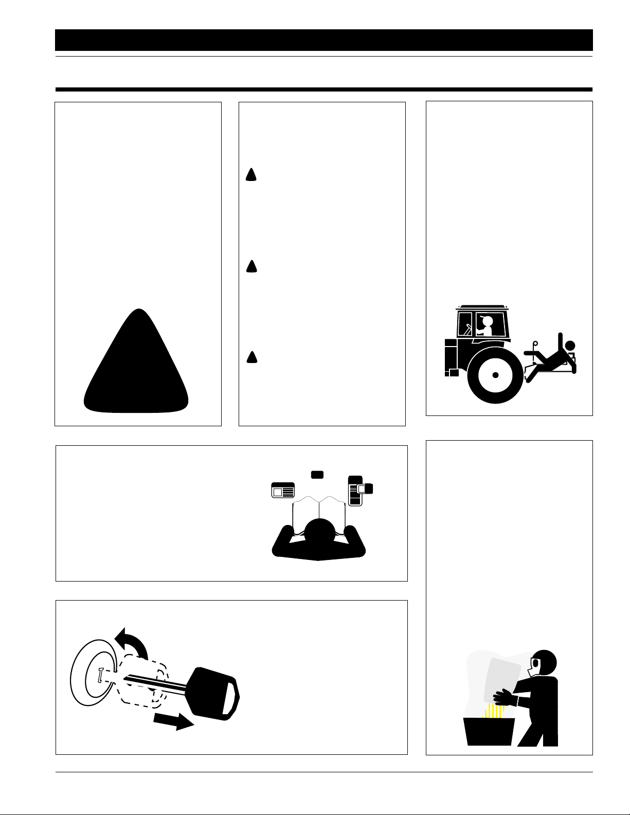
Look for Safety Symbol
The SAFETY ALERT SYMBOL indicates there is a potential hazard to
personal safety involved and extra
safety precaution must be taken.
When you see this symbol, be alert
and carefully read the message that
follows it. In addition to design and
configuration of equipment, hazard
control and accident prevention are
dependent upon the awareness,concern, prudence and proper training of
personnel involved in the operation,
transport, maintenance and storage
of equipment.
!
Be Aware of Signal Words
Signal words designate a degree or
level of hazard seriousness. The signal words are:
!
DANGER!
Indicates an imminently hazardous
situation which, if not avoided, will
result in death or serious injury. This
signal word is limited to the most
extreme situations, typically for
machine components that, for functional purposes, cannot be guarded.
!
WARNING!
Indicates a potentially hazardous situation which, if not avoided, could
result in death or serious injury, and
includes hazards that are exposed
when guards are removed. It may
also be used to alert against unsafe
practices.
CAUTION!
!
Indicates a potentially hazardous situation which, if not avoided, may
result in minor or moderate injury. It
may also be used to alert against
unsafe practices.
Keep Riders
Off Machinery
▲ Riders obstruct the operator’s
view. They could be struck by foreign objects or thrown from the
machine.
▲ Never allow children to operate
equipment.
For Your Protection
▲ Thoroughly read and understand
Safety Labels, page 4,
▲ Read all instructions noted on the
labels.
OFF
Shutdown and Storage
▲ Lower machine to ground, put
tractor in park, turn off engine,
and remove the key.
▲ Detach and store implements in a
area where children normally do
not play. Secure implement by
using blocks and supports.
Handle
Chemicals Properly
▲ Wear protective clothing.
▲ Handle all chemicals with care.
▲ Follow instructions on container
label.
▲ Use agricultural chemicals prop-
erly. Improper use can seriously
injure persons, animals, plants,
soil and property.
▲ Do not inhale smoke from any
type of chemical fire. This is a
serious health hazard.
▲ Store or dispose of unused chem-
icals as specified by the chemical
manufacturer.
5/11/05
Models ADI334 and ADI345 Air Drill Implement 160-195M
1
Important Safety Information
Great Plains Mfg., Inc.
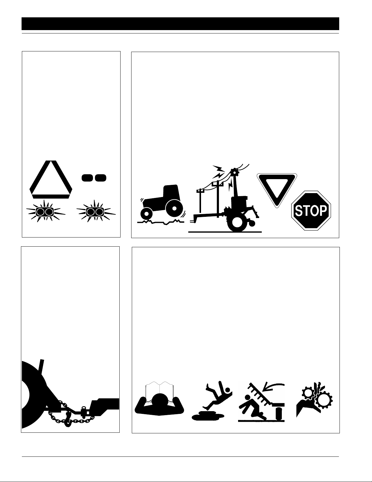
Use Safety
Lights and Devices
▲ Slow moving tractors, self-pro-
pelled equipment and towed
implements can create a hazard
when driven on public roads. They
are difficult to see, especially at
night.
▲ Flashing warning lights and turn
signals are recommended whenever driving on public roads. Use
lights and devices provided with
implement.
Transport
Machinery Safely
▲ Comply with state and local laws.
▲ Maximum transport speed for
implement is 20 mph. DO NOT
EXCEED. Never travel at a speed
which does not allow adequate
control of steering and stopping.
Some rough terrains require a
slower speed.
▲ Do not transport implement
unless it is attached to an air drill
cart.
▲ Keep clear of overhead power
lines when folding, unfolding or
transporting.
▲ Transport with channel locks in
place.
▲ Sudden braking can cause a
towed load to swerve and upset.
Reduce speed if towed load is not
equipped with brakes.
▲ Use the following ratios as a max-
imum-speed guide.
20 mph when towed weight is
less than or equal to tractor
weight.
10 mph when towed weight is
double tractor weight.
IMPORTANT:Do not tow a load
that is more than double tractor
weight.
Use A Safety Chain
▲ Use a safety chain to help con-
trol drawn machinery should it
separate from the tractor drawbar.
▲ Use a chain with the strength
rating equal to or greater than
the total weight of the towed
machinery.
▲ Attach the chain to the tractor
drawbar support or other specified anchor location. Allow only
enough slack in the chain to permit turning.
▲ Do not use safety chain for tow-
ing.
Practice Safe Maintenance
▲ Understand procedure before
doing work. Use proper tools and
equipment. Refer to “Mainte-
nance and Lubrication,” page
25, for additional information.
▲ Work in a clean, dry area.
▲ Lower the implement to the
ground, put tractor in park, turn off
engine, and remove key before
performing maintenance.
▲ Install all transport locks as
explained under Lifting the Drill,
“Operating Instructions,” page 16,
before working underneath the
raised drill.
▲ Do not grease or oil implement
while it is in operation.
▲ Disk edges are sharp. Be careful
when working in this area.
▲ Disconnect battery ground cable
(-) before servicing or adjusting
electrical systems or before welding on implement.
▲ Inspect all parts. Make sure parts
are in good condition and installed
properly.
▲ Remove buildup of grease, oil or
debris.
▲ Remove all tools and unused
parts from implement before operation.
Models ADI334 and ADI345 Air Drill Implement 160-195M 5/11/05
2
Great Plains Mfg., Inc.
Important Safety Information
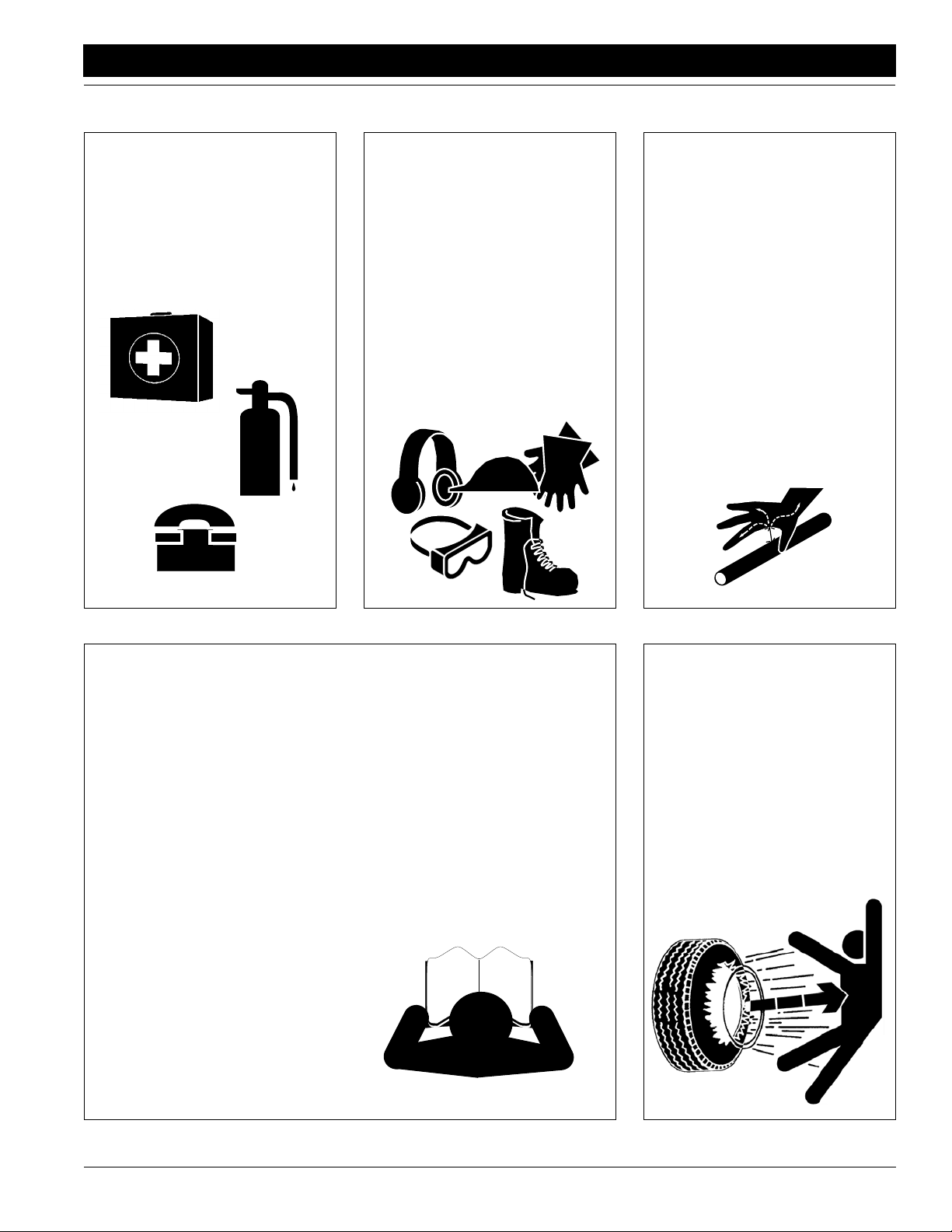
Prepare for Emergencies
▲ Be prepared if a fire starts.
▲ Keep a first aid kit and fire extin-
guisher handy.
▲ Keep emergency numbers for
doctor, ambulance, hospital and
fire department near phone.
911
Wear
Protective Equipment
▲ Wear protective clothing and
equipment.
▲ Wear clothing and equipment
appropriate for the job. Avoid
loose-fitting clothing.
▲ Wear suitable hearing protection
such as earmuffs or earplugs.
Prolonged exposure to loud noise
can cause hearing impairment or
loss.
▲ Avoid wearing radio headphones
while operating machinery. Operating equipment safely requires
full attention.
Avoid High
Pressure Fluids Hazard
▲ Relieve hydraulic pressure before
disconnecting lines. Escaping
fluid under pressure can penetrate the skin, causing serious
injury.
▲ Use a piece of paper or card-
board, NOT BODY PARTS, to
check for suspected leaks.
▲ Wear protective gloves and safety
glasses or goggles when working
with hydraulic systems.
▲ If an accident occurs, see a doc-
tor immediately. Any fluid injected
into the skin must be surgically
removed within a few hours or
gangrene may result.
Safety at All Times
Thoroughly read and understand the
instructions given in this manual
before operation. Refer to Safety
Labels, page 4. Read all instructions
noted on the labels.
▲ Operator should be familiar with
all implement functions.
▲ Operate implement from the
driver’s seat only.
▲ Do not leave tractor or implement
unattended with engine running.
▲ Do not dismount a moving tractor.
Dismounting a moving tractor
could cause serious injury or
death.
▲ Do not stand between the air drill
cart and implement while hitching.
▲ Keep hands, feet and clothing
away from power-driven parts.
▲ Wear snug-fitting clothing to avoid
entanglement with moving parts.
▲ Watch out for overhead power
lines, trees, etc., when raising,
folding, unfolding and transporting
the implement.
▲ Make sure all persons are clear of
working area.
▲ Do not turn tractor too tight, caus-
ing implement to ride up on
wheels. This could result in injury
or equipment damage.
▲ Keep away and keep others away
when folding or unfolding implement.
Tire Safety
▲ Tire changing can be dangerous
and should be performed by
trained personnel using the correct tools and equipment.
▲ When inflating tires, use a clip-on
chuck and extension hose long
enough to allow you to stand to
one side–NOT in front of or over
the tire assembly. Use a safety
cage if available.
▲ When removing and installing
wheels, use wheel-handling
equipment adequate for the
weight involved.
5/11/05
Models ADI334 and ADI345 Air Drill Implement 160-195M
3
Important Safety Information
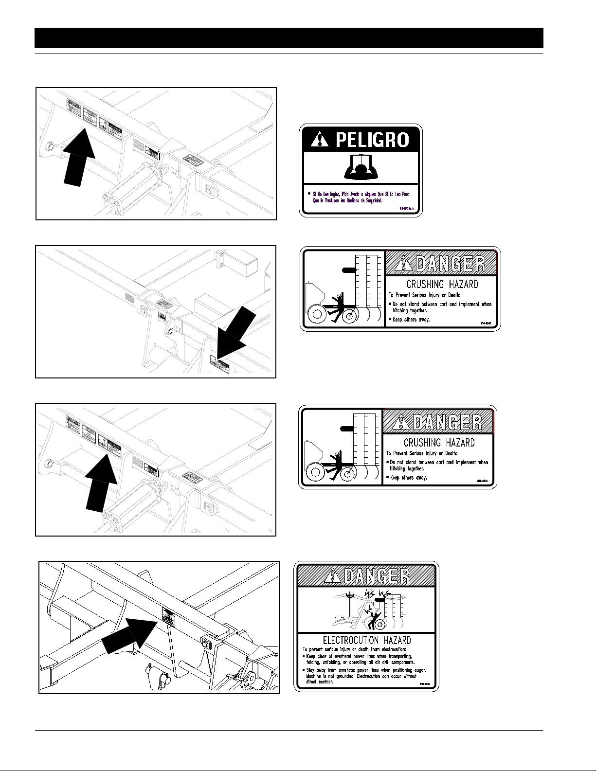
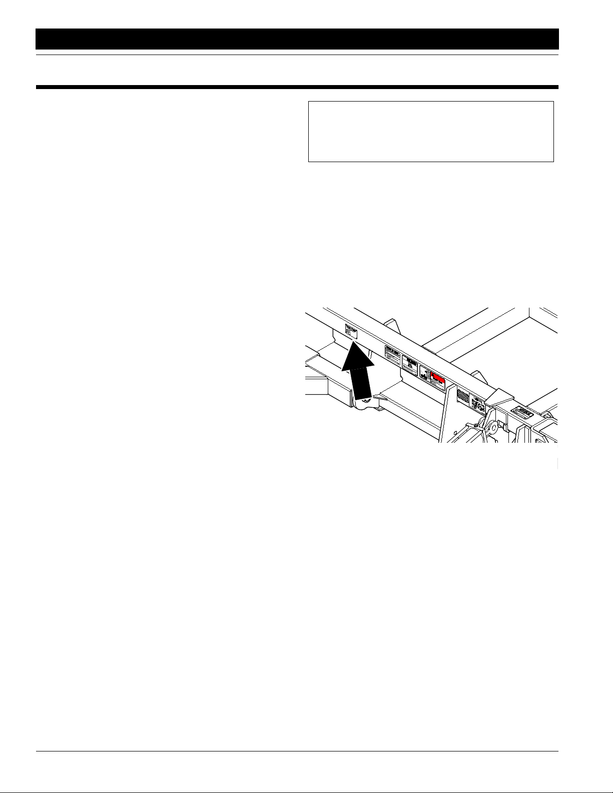
Safety Labels
Your implement comes equipped with all safety labels in place.
They were designed to help you safely operate your implement.
1. Read and follow label directions.
2. Keep all safety labels clean and legible.
3. Replace all damaged or missing labels. Order new labels
from your Great Plains dealer. Refer to this section for
proper label placement.
Great Plains Mfg., Inc.
4. When ordering new parts or components, also request corresponding safety labels.
5. To install new labels:
a. Clean the area on which the label is to be placed.
b. Peel backing from label. Press firmly on surface,
being careful not to cause air bubbles under label.
16558
818-055C
Slow Moving VehicleLabel
838-265C
Amber Reflector (Two labels–one each side of frame)
14356
838-265C
Amber Reflector (Both rear
castor wheels)
16558
Models ADI334 and ADI345 Air Drill Implement 160-195M 5/11/05
4
Great Plains Mfg., Inc.
Important Safety Information
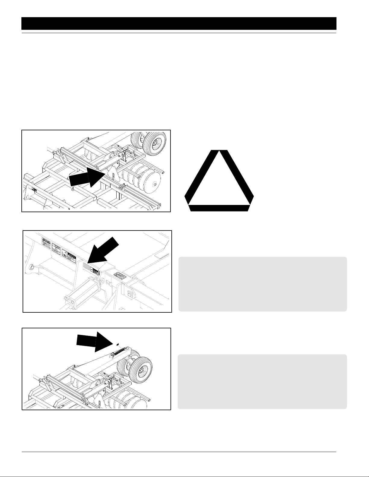
383-266C
Red Reflector (Two labels–one on each dual,
center gauge wheels)
14347
383-266C
Red Reflector (Both rear
castor wheels)
14352
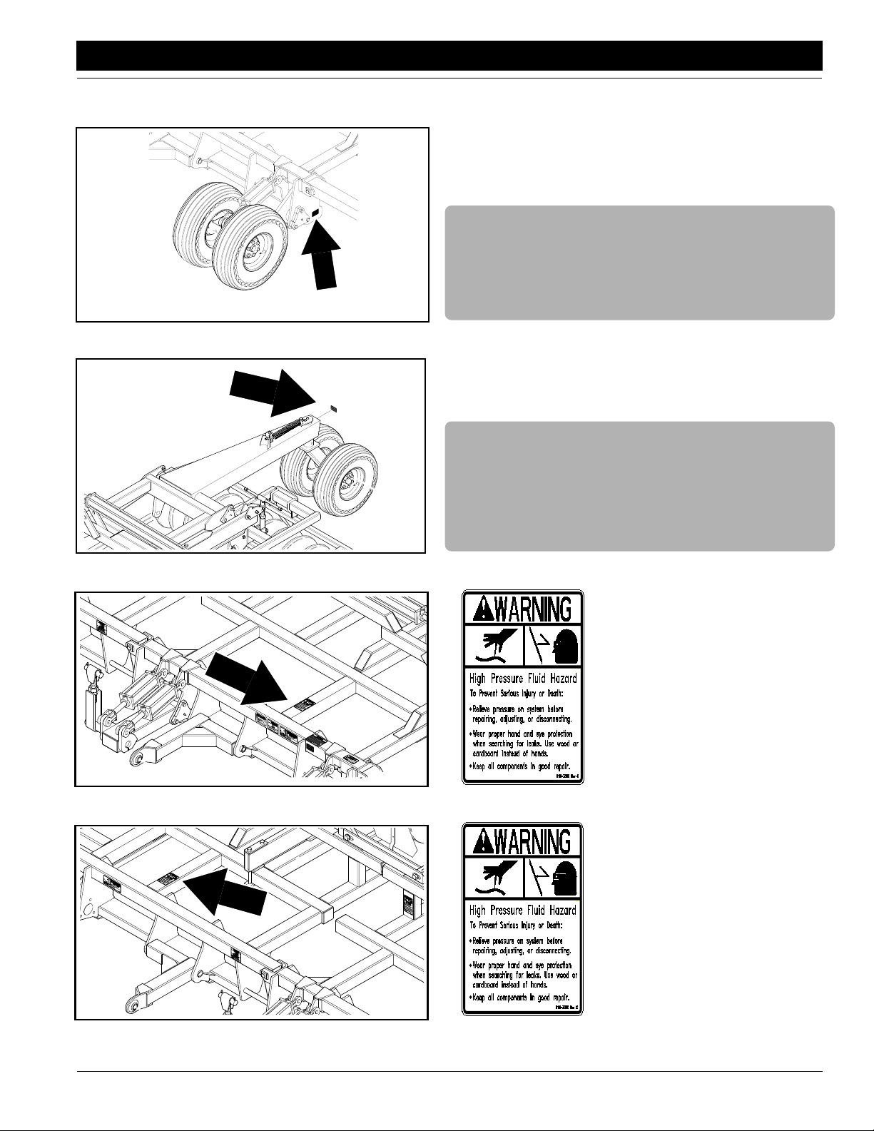
16554
818-339C
High Pressure
14352
5/11/05
818-339C
High Pressure
Models ADI334 and ADI345 Air Drill Implement 160-195M
5
Important Safety Information
Great Plains Mfg., Inc.
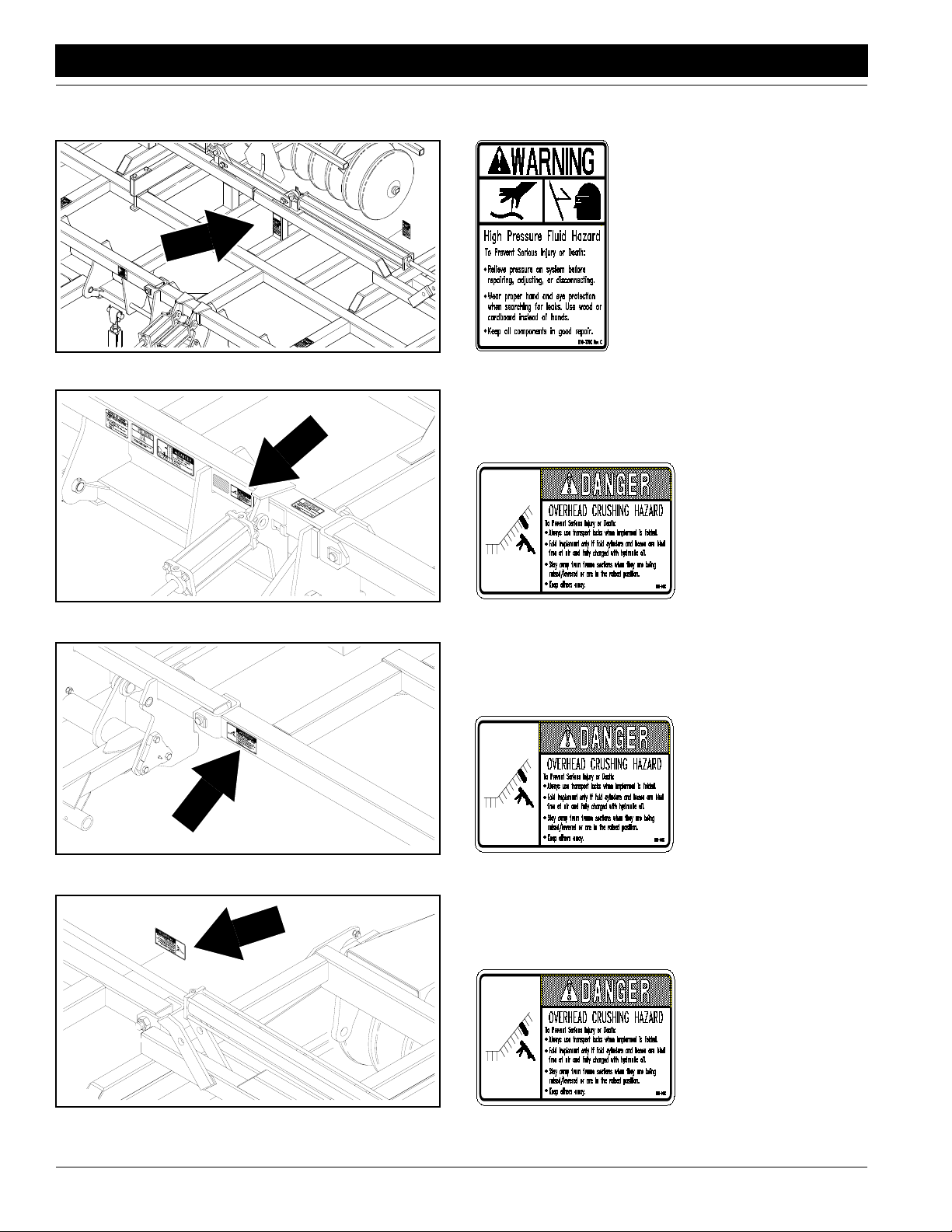
14352
14356
818-339C
High Pressure
818-046C
Charge Fold Cylinder
818-046C
14348
Charge Fold Cylinder
818-046C
14349
Models ADI334 and ADI345 Air Drill Implement 160-195M 5/11/05
6
Charge Fold Cylinder
Great Plains Mfg., Inc.
Important Safety Information
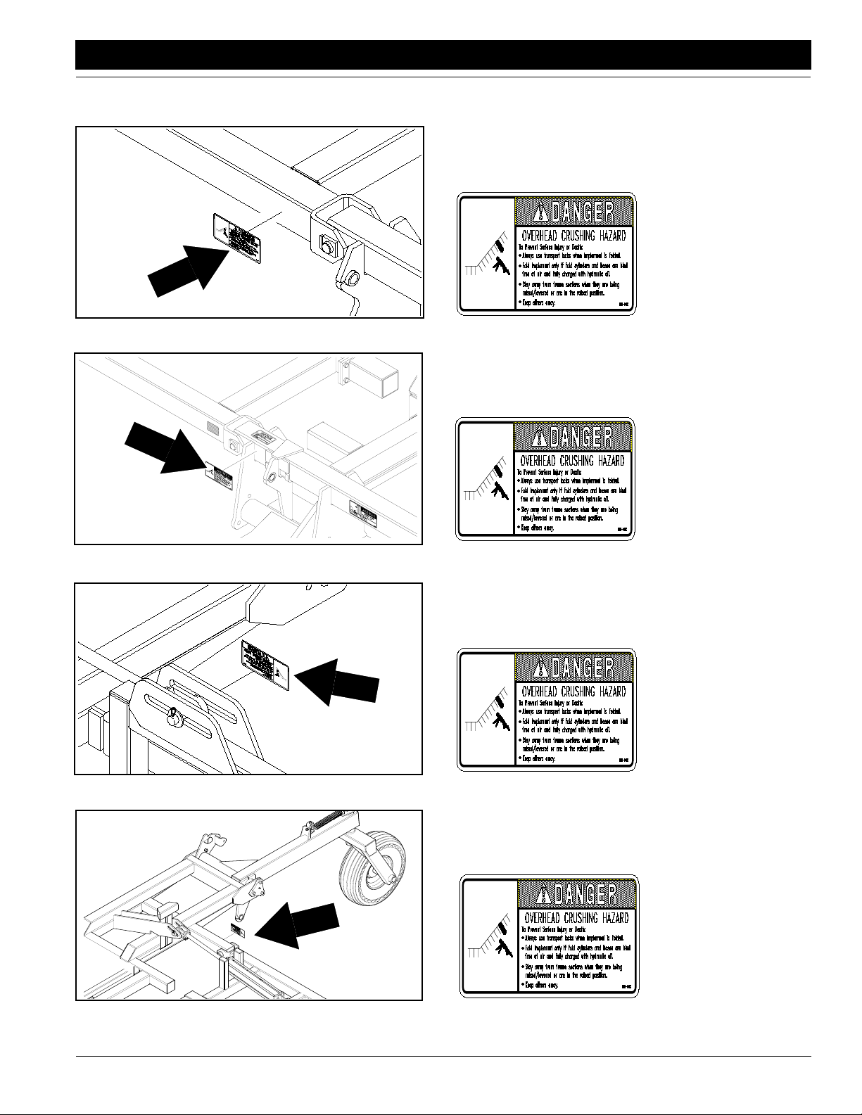
14354
818-046C
Charge Fold Cylinder
14350
14355
818-046C
Charge Fold Cylinder
818-046C
Charge Fold Cylinder
5/11/05
16560
818-046C
Charge Fold Cylinder
(Two labels–one each
side of frame)
Models ADI334 and ADI345 Air Drill Implement 160-195M
7
Important Safety Information
14356
Great Plains Mfg., Inc.
818-557C
Cannot Read English
14805
14356
818-624C
Crush Ad/Implement
818-624C
Crush Ad/Implement
14351
Models ADI334 and ADI345 Air Drill Implement 160-195M 5/11/05
8
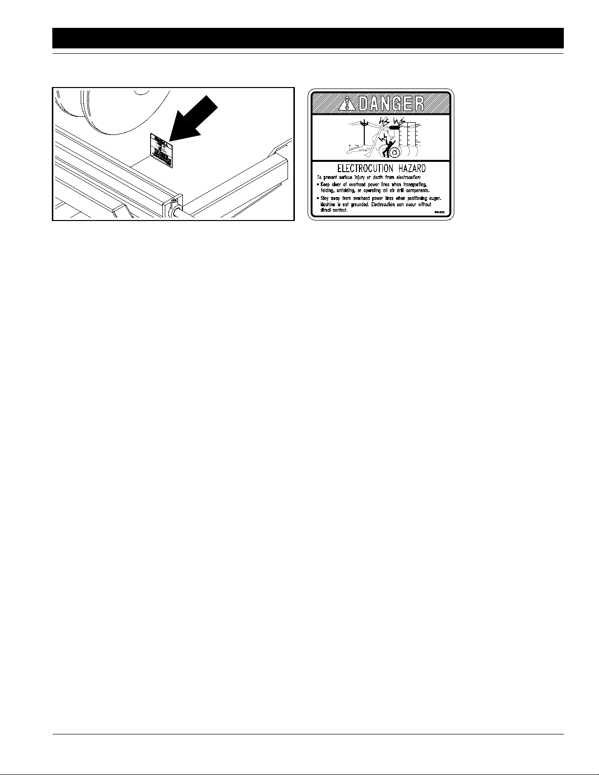
818-627C
Electrocution Auger
Great Plains Mfg., Inc.
Important Safety Information
14808
818-627C
Electrocution Auger
5/11/05
Models ADI334 and ADI345 Air Drill Implement 160-195M
9
Introduction
Introduction
Great Plains welcomes you to its growing family of new
product owners. This implement has been designed with
care and built by skilled workers using quality materials.
Proper assembly, maintenance and safe operating practices will help you get years of satisfactory use from this
machine.
Great Plains Mfg., Inc.
IMPORTANT: A crucial point of information related to
the preceding topic. For safe and correct oper ation,
read and follow the directions provided before continuing.
Description of Unit
The three-rank, air-drill implement is a towed seeding implement used with a Great Plains air-drill cart. Seed is delivered by a pressurized air stream to the floating-hoe
openers via primary seed hoses, distribution towers and
secondary seed hoses.
The implement has a working width of 34 or 45 feet. The
implement has three ranks of staggered openers for easy
residue flow.Opener depth is controlled by adjusting a hydraulicstop and the press wheels. Press wheels followthe
openers to firm and close the seedbed. An electric-clutch
drivewithanadjustableheightswitchturnsseeding off automatically for headland turns.
Openers and press wheels are spaced over four frame
sections on the 34-foot or six sections on the 45-foot implement. Floating arms link the cart to the implement for
increased front-to-rear flexibility.
The implement folds to a transportheight of 15 feet, eight
inches (45-foot drill) or 13 feet, two inches (35-foot drill).
Rear castor wheels are used for transport and field turns
and are lifted for seeding.
Intended Usage
This machine is to be used primarily for seeding small
grains and legumes in conventional tillage. It can also be
used for seeding other crops in reduced-tillage applications.
NOTE: Useful information related to the preceding topic.
Owner Assistance
If customer service or repair parts are needed, contact
your Great Plains dealer. They have trained personnel,
parts and service equipment specially designed for Great
Plains products.
Your machine’sparts were specially designed and should
be replaced with Great Plains parts only.Always use the
serial and model number when ordering parts from your
Great Plains dealer. The serial number plate is located as
shown in Figure A.
14595
Figure A
Serial Number Plate Location
Using This Manual
Thismanualis designed to help familiarizeyou with safety,
set-up, operation, adjustment, troubleshooting and maintenance. Read this manual and follow the recommendations to help ensure safe and efficient operation.
Fill out the warranty sheet with your dealer at the time of
purchase.Giveyour dealer the completed white copy and
send the pink copy to Great Plains.Keepyour yellow copy
in the manual for use when corresponding with your dealer.
Theinformation in this manual is current at printing. Some
parts may change to assure top performance.
Definitions
Right and left as used in this manual are determined by
facingthe direction the machine will travelwhile in use unless otherwise stated.
Models ADI334 and ADI345 Air Drill Implement 160-195M 5/11/05
10
Your Great Plains dealer wants you to be satisfied with
your new machine. If you do not understand any part of
this manual or are not satisfied with the service received,
please take the following actions:
1. Discuss the matter with yourdealer servicemanager.
Makesure theyare awareof anyproblemsso theycan
assist you.
2. If you are still not satisfied, seek out the dealership
owner or general manager.
3. For further assistance, write to:
Product Support
Great Plains Mfg. Inc., Service Department
P.O. Box 5060
Salina, KS 67402-5060
 Loading...