

Page 1
Great Plains Mfg., Inc.
Installation Instructions 1
Auger Carrier Update
ADC2350 Air Carts
Used with:
• ADC2350B
General Information
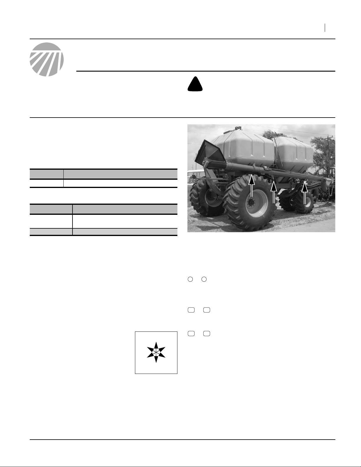
These instructions explain how to install an Auger Carrier
Update on a pre-2009 “pull-behind” air cart. This update
improves clearance between the auger and air drill in
some configurations. It also provides a new auger pivot
mount that eases any future major auger maintenance.
These instructions apply to an installation of:
Kit Kit Description
166-247A
One kit updates one air cart.
Cart Model Kit Compatibility
ADC2350B
ADC2350 Not compatible and not required.
ADC2350B AUGER CARRIER UPDATE
serial number A1159T or lower, which
includes all manufactured in 2008
When you see this symbol, the subsequent instructions
and warnings are serious - follow without exception.
!
Your life and the lives of others depend on it!
Figure 1
Auger Update Sites
29370
Related Documents
Have the Operator Manual at hand for cart and drill
movements.
167-085M Operator, ADC2350B cart
196-444M Operator, 3N-4010HDA implement
Have the current Parts Manual at hand for parts ID.
167-085P ADC2350B
Notations and Conventions
“Left” and “Right” are facing in the
direction of machine travel. An orientation rose in the line art illustrations
shows the directions of Left, Right,
Front, Back, Up, Down.
U
F
L
D
R
B
Call-Outs
1 9
to
11 39
to
51 63
to
Single-digit callouts identify components in
the currently referenced Figure or Figures.
These numbers may be reused for different
items from page to page.
Two-digit callouts in the range 11 to 39 reference new parts from the new parts lists
beginning on page 8.
Two-digit callouts in the range 51 to 63 reference affected existing parts from the table on
page 10. The descriptions match those in
your Parts Manual. The narrative and table
indicate any re-use of the parts.
©Copyright 2009 Printed 03/05/2009 166-255M
Page 2
2 Auger Carrier Update
Before You Start
Compatibility
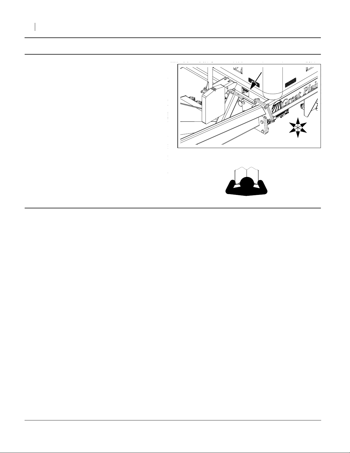
Refer to Figure 2
Check the cart serial number plate against the table on
page 1. Verify that
the model is ADC2350B, and
the serial number is A1159T or lower.
Great Plains Mfg., Inc.
Inventory
1. Make sure all parts are present.
Comprehension
2. Review these instructions. Make sure the installers
understand where each part or assembly is
installed, and what tools are required for the task.
Note: Illustrations in this manual, based on the parts
manuals for this family of drills, may show
exploded views that are fully disassembled. Rely
on the instructions for required disassembly and
reassembly steps.
Pre-Assembly Preparation
Tools Required
• hoist with 300 pounds (150 kg) capacity at a height of
ten feet (3m), for supporting the dismounted auger
• updated cart Parts Manual (see page 1)
• basic hand tools, including:
9
⁄
in / K / 7.2mm punch or drill.
32
Work Location
3. Clear the auger of any residual seed or fertilizer.
4. Move the air cart to a location with:
• adequate illumination,
• hoist access, and;
• a means of obtaining lower than normal depres-
sion of the inlet end of the auger (about
18in (46cm) below normal ground level), to
relieve as much tension as possible from the
auger balance springs; for example:
- a dock, with auger off right edge,
- a solid platform or blocks under right main tire,
- jack and supports for right side of frame.
Note: If the depression cannot be accomplished at the
hoist location, disconnect the springs (step 23 and
24), then move the cart to the hoist site.
Note: Once the old springs are disconnected, auger end
depression is no longer required. The new spring
anchor engages at zero spring extension.
R
F
Figure 2
ADC2350B Serial Number Plate
U
B
L
D
26428
166-255M 03/05/2009
Page 3
Great Plains Mfg., Inc.
Pre-Assemble Components
Assemble New Auger Carrier Latches
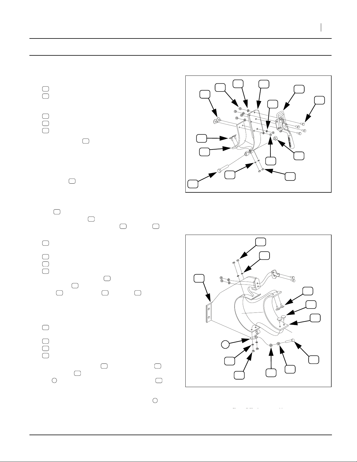
Refer to Figure 3
5. Select two (2) each new:
13
166-188H AUGER TRANS LATCH PULL BEHIND
39
816-570C 8 INCH AUGER CLAMP PAD
(this is the shorter of the two sizes of EPDM pads)
and eight (8) sets new:
25
802-888C ELEVATOR BOLT 1/4-20X3/4 PLT:
32
804-006C WASHER LOCK SPRING 1/4 PLT
26
803-006C NUT HEX 1/4-20 PLT
6. The clamp pad may have two, four or no holes,
and may or may not have adhesive on one side,
protected by release paper. If four holes are not
present, it is necessary to assembly-drill them.
39
25
25
39
27
33
Installation Instructions 3
13
17
32
18
29
26
Position the pad so that it is centered in the latch
weldment . Mark holes for fractional size
(letter size K, 7.2mm). Remove pad and punch or
drill holes.
7. Remove any release paper. Position a clamp
pad , adhesive side to inside of latch face. Insert
the elevator bolts through the inside of the pad
and secure with lock washers and nuts
8. Select the latch side of two (2) each new:
17
800-285C AUGER LATCH CLAMP
and eight (8) sets new:
18
802-007C HHCS 5/16-18X3/4 GR5
33
804-009C WASHER LOCK SPRING 5/16 PLT
27
803-008C NUT HEX 5/16-18 PLT
Mount the latch clamps at the top of the latch
weldments , inside the double break, using the
bolts , lock washers and nuts
13
39
25
32 26
17
13
18 33 27
9
⁄
in
32
Assemble New Auger Carrier Rests
Refer to Figure 4
9. Select two new:
12
166-187H AUGER CARRIER PULL BEHIND
and one each new:
21
802-114C HHCS 3/8-16X2 1/2 GR5
28
803-014C NUT HEX 3/8-16 PLT
34
804-013C WASHER LOCK SPRING 3/8 PLT.
10. Loosely thread the nut fully onto the bolt , add
lock washer , and loosely thread fully into coupler
112
nut at the bottom of the carrier weldment .
34
28 21
22
12
1
32
32
Figure 3
Auger Latch
26
26
32
34
26
29373
25
25
38
21
28
This carrier is designated the rear carrier, and is the
only one with a stop bolt in the coupler nut .
03/05/2009 166-255M
1
Figure 4
(Rear) Auger Carrier
29373
Page 4
4 Auger Carrier Update
11. Select two (2) each new:
38
816-562C 8 INCH AUGER REST PAD
(this is the longer of the two sizes of EPDM pads)
and eight (8) sets new:
25
802-888C ELEVATOR BOLT 1/4-20X3/4 PLT:
32
804-006C WASHER LOCK SPRING 1/4 PLT
26
803-006C NUT HEX 1/4-20 PLT
27
12
Great Plains Mfg., Inc.
33
17
12. The clamp pad may have no holes (or two holes,
38
or four), and may or may not have adhesive on one
side, protected by release paper. If four holes are
not present, it is necessary to assembly-drill them.
Position the pad so that it is centered in the latch
weldment . Mark holes for fractional size
13
9
⁄
in
32
(letter size K, 7.2mm). Remove pad and punch or
drill holes.
13. Remove any release paper. Position a rest pad ,
38
adhesive side to inside of latch face. Insert the elevator bolts through the inside of the pad and
secure with lock washers and nuts .
25
32 26
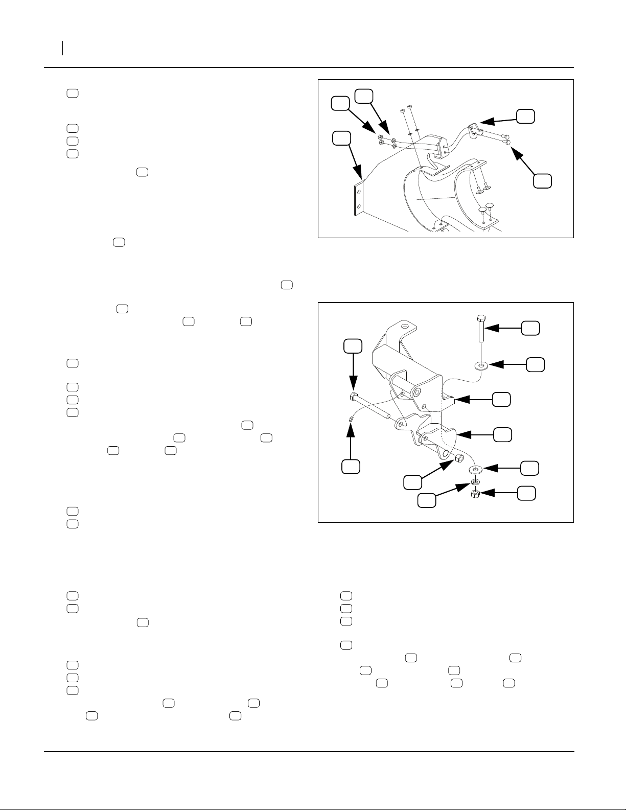
Refer to Figure 5
14. Select the hook side of two (2) each new:
17
800-285C AUGER LATCH CLAMP
and four (4) sets new:
18
802-007C HHCS 5/16-18X3/4 GR5
33
804-009C WASHER LOCK SPRING 5/16 PLT
27
803-008C NUT HEX 5/16-18 PLT
Mount the hook side of the latch clamp at the top
of the carrier weldment , using the bolts , lock
washers and nuts .
33 27
12 18
17
Assemble New Auger Carriers
Refer to Figure 4 on page 3 and Figure 3
15. Select two (2) sets new:
22
802-130C HHCS 1/2-13X2 1/2 GR5
29
803-019C NUT LOCK 1/2-13 PLT
Mount latch assemblies at the bottom of carriers.
Assemble New Pivot Mount
Refer to Figure 6
16. Select one each new:
15
166-190H 20’ AUGER PIVOT MOUNT WELDMENT
16
800-001C GREASE ZERK STRAIGHT 1/4-28
Screw the zerk into the
16
the mount cross-tube.
17. Select one each new:
14
166-189H AUGER BALANCE SPRING ANCHOR
20
802-045C HHCS 1/2-13X5 GR5
29
803-019C NUT LOCK 1/2-13 PLT
Mount spring anchor on pivot mount with
20 29
bolt . Do not fully tighten lock nut .
1
⁄
-28 threaded hole of
4
14 15
Figure 5
Auger Carrier Latch Hook
20
15
14
16
29
35
Figure 6
Assemble Pivot Mount
18. Select one each new:
23
802-412C HHCS 1/2-13X2 3/4 FTHD
35
804-015C WASHER LOCK SPRING 1/2 PLT
30
803-020C NUT HEX 1/2-13 PLT
and two:
37
804-113C WASHER FLAT 1/2 USS HARD PLT
Swing anchor up into pivot mount . Insert
23 37
bolt with flat washer . Add second flat
washer , lock washer and nut . Thread nut
on just a few turns. Do not fully seat nut at this time.
14 15
37 35 30
30
18
29373
23
37
37
29372
166-255M 03/05/2009
Page 5

Great Plains Mfg., Inc.
Remove Old Parts
19. Unlatch the auger, and swing it out as if loading the
forward hopper.
Remove Old Carriers
Refer to Figure 7
20. At each existing carrier, remove two (2) sets each,
or four (4) sets total:
55
802-034C HHCS 1/2-13X1 1/4 GR5
62
804-015C WASHER LOCK SPRING 1/2 PLT
59
803-020C NUT HEX 1/2-13 PLT
These fasteners are not re-used.
21. Remove one each:
53
166-179H
54
166-180H AUGER REAR CARRIER PULL BEHIND
These assemblies are not re-used.
AUGER FRNT CARRIER PULL BEHIND
59
55
Installation Instructions 5
62
54
3
2
22. Support auger with hoist. Loops at lower handles
and between the outlet spout and motor housing ,
can safely support the auger without slipping.
3
Disconnect Balance Springs
Refer to Figure 8
23. Take steps to permit depressing the auger inlet end
below normal ground level, to fully relieve tension in
the counterbalance springs .
24. Lift the springs off the upper pin .
63
807-016C SPRING RESET HOE
Leave springs on auger for re-use.
63
4
Dismount Auger
25. Check that the hoist is supporting the auger.
Remove one set:
56
802-045C HHCS 1/2-13X5 GR5
58
803-019C NUT LOCK 1/2-13 PLT
These parts are not re-used.
26. Use hoist to lift auger clear of pivot mount .
51
Remove Old Pivot Mount
Refer to Figure 8 and Figure 12 on page 10
27. Remove one each:
60
803-025C NUT HEX 3/4-10 PLT NYLOCK
57
802-469C HHCS 3/4-10X8 GR5 PLT
61
804-008C WASHER FLAT 3/4 HARD USS
51
166-071H AUGER PIVOT BRACKET WELDMENT
These parts are not re-used.
2
53
Figure 7
Remove Old Carriers
26264
51
56
60
58
63
57
4
Figure 8
Disconnect Springs
29374
03/05/2009 166-255M
Page 6

6 Auger Carrier Update
Install New Parts
Install New Pivot Mount
Refer to Figure 9
28. Select one each new:
24
802-469C HHCS 3/4-10X8 GR5 PLT
36
804-093C WASHER FLAT 3/4 HARD ASTMF436
31
803-025C NUT HEX 3/4-10 PLT NYLOCK
15
166-190H
Place the washer on the bolt . Secure the
pivot mount , assembled at step 16, on the outer
52 31
arm using lock nut .
Re-Mount Auger
29. Select one each new:
20
802-045C HHCS 1/2-13X5 GR5
29
803-019C NUT LOCK 1/2-13 PLT
30. Use hoist to align auger pivot lugs with bottom
cross-tube of spring anchor . Secure auger to
anchor with bolt and lock nut .
20’ AUGER PIVOT MOUNT WELDMENT
36 24
15
5
14
20 29
Great Plains Mfg., Inc.
7
15
24
30
52
36
31
35
19
20
14
6
5
29
Figure 9
Install Pivot Mount and Auger
29372
Install New Carriers
31. Select one each new:
6
Rear carrier from step 10 (with stop bolt).
7
Front carrier from page 4 (without stop bolt)
and four sets new:
19
802-034C HHCS 1/2-13X1 1/4 GR5
35
804-015C WASHER LOCK SPRING 1/2 PLT
30
803-020C NUT HEX 1/2-13 PLT
Mount carriers at locations where old carriers were
removed. Open latches.
Re-Connect Balance Springs
Refer to Figure 10
32. Adjust hoist to allow auger to swing to normal loading position (inlet low).
33. Connect top end of springs to lower cross-tube
of new anchor . Tighten bolt and nut fully.
14 23 30
63
Auger Closeout
34. Check range of motion of new auger pivot mount.
35. Adjust rear clamp stop so that latch clamp cannot strike rear tire.
36. Stow auger in new carriers.
37. Adjust new clamps so that handles snap into position, but do not crush auger tube.
21
21
63
Figure 10
Re-Connect Springs
14
23
30
29375
166-255M 03/05/2009
Page 7

Great Plains Mfg., Inc.
Auger Maintenance
Installation Instructions 7
Auger Storage Clamps
50
2 clamps
Type of Lubrication: Spray
Quantity: Coat thoroughly
Auger Swing Arm: Mount Pivot (Pivot)
50
1 zerk each pivot; 1 total
Type of Lubrication: Grease
Quantity: Until Grease emerges
26329
29372
Auger Swing Arm: Mount Pivot (Tilt)
50
1 zerk each pivot; 1 total
Type of Lubrication: Grease
Quantity: Until Grease emerges
29377
03/05/2009 166-255M
Page 8

8 Auger Carrier Update
Appendix
New Parts
Great Plains Mfg., Inc.
36
24
30
35
19
12
32
27
26
33
34
17
28
18
21
38
25
20
15
16
20
31
37
35
25
23
14
30
37
32
52
63
26
13
33
27
39
17
22
29
Figure 11
New Parts
166-255M 03/05/2009
29376
Page 9

Great Plains Mfg., Inc.
Installation Instructions 9
This manual covers the installation of several different
hold-down kits. Parts are listed for each kit separately.
Quantities are units (“ea”).
166-247A Kit Contents
Callout
11
12
13
14
15
16
17
18
19
20
21
22
23
24
25
26
27
28
29
30
31
32
33
34
35
36
37
38
39
51 63
-
Quantity
in Kit
1 166-255M
2 166-187H
2 166-188H
1 166-189H
1 166-190H
1 800-001C
2 800-285C
12 802-007C
4 802-034C
2 802-045C
1 802-114C
2 802-130C
1 802-412C
1 802-469C
16 802-888C
16 803-006C
16 803-008C
1 803-014C
4 803-019C
5 803-020C
1 803-025C
16 804-006C
12 804-009C
1 804-013C
5 804-015C
1 804-093C
2 804-113C
2 816-562C
2 816-570C
- Existing See next two pages.
Part
Number
MANUAL 2350B AUGER CARRIER UPD
AUGER CARRIER PULL BEHIND
AUGER TRANS LATCH PULL BEHIND
AUGER BALANCE SPRING ANCHOR
20’ AUGER PIVOT MOUNT WELDMENT
GREASE ZERK STRAIGHT 1/4-28
AUGER LATCH CLAMP
HHCS 5/16-18X3/4 GR5
HHCS 1/2-13X1 1/4 GR5
HHCS 1/2-13X5 GR5
HHCS 3/8-16X2 1/2 GR5
HHCS 1/2-13X2 1/2 GR5
HHCS 1/2-13X2 3/4 FTHD
HHCS 3/4-10X8 GR5 PLT
ELEVATOR BOLT 1/4-20X3/4 PLT
NUT HEX 1/4-20 PLT
NUT HEX 5/16-18 PLT
NUT HEX 3/8-16 PLT
NUT LOCK 1/2-13 PLT
NUT HEX 1/2-13 PLT
NUT HEX 3/4-10 PLT NYLOCK
WASHER LOCK SPRING 1/4 PLT
WASHER LOCK SPRING 5/16 PLT
WASHER LOCK SPRING 3/8 PLT
WASHER LOCK SPRING 1/2 PLT
WASHER FLAT 3/4 HARD ASTMF436
WASHER FLAT 1/2 USS HARD PLT
8 INCH AUGER REST PAD
8 INCH AUGER CLAMP PAD
The part call-out numbers in this list match all Figures in
these installation instructions. Part descriptions match
those in your updated Parts Manual.
Part Description
03/05/2009 166-255M
Page 10

10 Auger Carrier Update
Existing Parts Affected
Great Plains Mfg., Inc.
59
62
54
55
57
61
51
56
52
58
60
63
53
Figure 12
Old Parts
166-255M 03/05/2009
26264
Page 11

Great Plains Mfg., Inc.
Installation Instructions 11
The following existing parts are involved in the kit installation. The Disposition column indicates whether the part
is left in place, moved or not re-used.
The part call-out numbers in the list matches all Figures
in the installation instructions. The descriptions match
those in your air cart Parts manual.
Callout Part No. Part Description Part Disposition
51
52
53
54
55
56
57
58
59
60
61
62
63
166-071H
166-169H
166-179H
166-180H
802-034C
802-045C
802-469C
803-019C
803-020C
803-025C
804-008C
804-015C
807-016C
AUGER PIVOT BRACKET WELDMENT Removed. Not re-used.
AUGER PIVOT ARM - OUTSIDE Partially dismantled. Left in place.
AUGER FRNT CARRIER PULL BEHIND Removed. Not re-used.
AUGER REAR CARRIER PULL BEHIND Removed. Not re-used.
HHCS 1/2-13X1 1/4 GR5 Removed. Not re-used.
HHCS 1/2-13X5 GR5 Removed. Not re-used.
HHCS 3/4-10X8 GR5 PLT Removed. Not re-used.
NUT LOCK 1/2-13 PLT Removed. Not re-used.
NUT HEX 1/2-13 PLT Removed. Not re-used.
NUT HEX 3/4-10 PLT NYLOCK Removed. Not re-used.
WASHER FLAT 3/4 HARD USS Removed. Not re-used.
WASHER LOCK SPRING 1/2 PLT Removed. Not re-used.
SPRING RESET HOE Partially dismantled. Left in place.
Abbreviations
ASTM
FTHD
GR5
HEX
HHCS
American Society for Testing and Materials
Full-Threaded
Grade 5
Hexagonal
Hex Head Cap Screw (Bolt)
PLT
UPD
USS
X
Plated
Update
United States Standard (heavy duty)
by
03/05/2009 166-255M
Page 12

12 Auger Carrier Update
Torque Values
Great Plains Mfg., Inc.
Bolt
Size
in-tpi
1
⁄4-20
1
⁄4-28
5
⁄16-18
5
⁄16-24
3
⁄8-16
3
⁄8-24
7
⁄16-14
7
⁄16-20
1
⁄2-13
1
⁄2-20
9
⁄16-12
9
⁄16-18
5
⁄8-11
5
⁄8-18
3
⁄4-10
3
⁄4-16
7
⁄8-9
7
⁄8-14
1-8
1-12
11⁄8-7
11⁄8-12
11⁄4-7
11⁄4-12
13⁄8-6
13⁄8-12
11⁄2-6
11⁄2-12
Bolt Head Identification
Bolt Head Identification
Bolt
Size
Grade 2 Grade 5 Grade 8 Class 5.8 Class 8.8 Class 10.9
1
N-m2ft-lb
7.4 5.6 11 8 16 12
8.5 6 13 10 18 14
15 11 24 17 33 25
17 13 26 19 37 27
27 20 42 31 59 44
31 22 47 35 67 49
43 32 67 49 95 70
49 36 75 55 105 78
66 49 105 76 145 105
75 55 115 85 165 120
95 70 150 110 210 155
105 79 165 120 235 170
130 97 205 150 285 210
150 110 230 170 325 240
235 170 360 265 510 375
260 190 405 295 570 420
225 165 585 430 820 605
250 185 640 475 905 670
340 250 875 645 1230 910
370 275 955 705 1350 995
480 355 1080 795 1750 1290
540 395 1210 890 1960 1440
680 500 1520 1120 2460 1820
750 555 1680 1240 2730 2010
890 655 1990 1470 3230 2380
1010 745 2270 1670 3680 2710
1180 870 2640 1950 4290 3160
1330 980 2970 2190 4820 3560
Torque tolerance + 0%, -15% of torquing values. Unless otherwise specified use torque values listed above.
3
N-m ft-lb N-m ft-lb
EOD
mm x pitch
M 5 X 0.8
M 6 X 1
M 8 X 1.25
M 8 X 1
M10 X 1.5
M10 X 0.75
M12 X 1.75
M12 X 1.5
M12 X 1
M14 X 2
M14 X 1.5
M16 X 2
M16 X 1.5
M18 X 2.5
M18 X 1.5
M20 X 2.5
M20 X 1.5
M24 X 3
M24 X 2
M30 X 3.5
M30 X 2
M36 X 3.5
M36 X 2
1. in-tpi = nominal thread diameter in inches-threads per inch
2. N· m = newton-meters
3. ft-lb = foot pounds
4. mm x pitch = nominal thread diameter in millimeters x thread
pitch
4
5.8 8.8 10.9
N-m ft-lb N-m ft-lb N-m ft-lb
43659 7
7 5 11 8 15 11
17 12 26 19 36 27
18 13 28 21 39 29
33 24 52 39 72 53
39 29 61 45 85 62
58 42 91 67 125 93
60 44 95 70 130 97
90 66 105 77 145 105
92 68 145 105 200 150
99 73 155 115 215 160
145 105 225 165 315 230
155 115 240 180 335 245
195 145 310 230 405 300
220 165 350 260 485 355
280 205 440 325 610 450
310 230 650 480 900 665
480 355 760 560 1050 780
525 390 830 610 1150 845
960 705 1510 1120 2100 1550
1060 785 1680 1240 2320 1710
1730 1270 2650 1950 3660 2700
1880 1380 2960 2190 4100 3220
Great Plains Manufacturing, Inc.
Corporate Office P.O. Box 5060
Salina, Kansas 67402-5060 USA
166-255M 03/05/2009
 Loading...