

Page 1
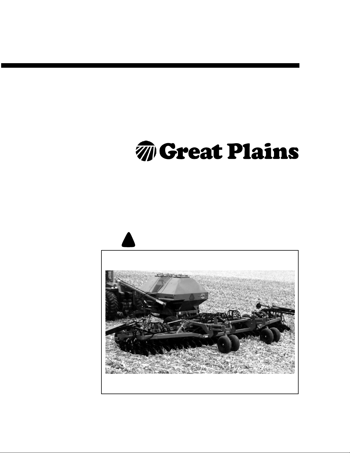
Export Predelivery Instructions
ADC2220 & NTA 3510
Air Drill Cart & Air Drill Implement
Manufacturing, Inc.
www.greatplainsmfg.com
Read the operator’s manual entirely. When you see this symbol, the subsequent
instructions and warnings are serious - follow without exception. Your life and
!
the lives of others depend on it!
16178
Cover illustration may show optional equipment not supplied with standard unit.
© Copyright 2005 Printed 3/3/2006
167-088Q-RUS
Page 2

Table of Contents
Great Plains Mfg., Inc.
Important Safety Information . . . . . . . . . . . . . . . 1
Introduction . . . . . . . . . . . . . . . . . . . . . . . . . . . . . 6
Description of Unit . . . . . . . . . . . . . . . . . . . . . 6
Intended Usage . . . . . . . . . . . . . . . . . . . . 6
Using This Manual . . . . . . . . . . . . . . . . . . . . . 6
Definitions . . . . . . . . . . . . . . . . . . . . . . . . 6
Assembly and Setup Assistance . . . . . . . . . . 6
Before You Start . . . . . . . . . . . . . . . . . . . . . . . 7
Pre-Assembly . . . . . . . . . . . . . . . . . . . . . . . . . . . 8
Tools Required . . . . . . . . . . . . . . . . . . . . . . . . 8
Pre-Assembly Checklist . . . . . . . . . . . . . . . . . 8
Unload Center Section Rack . . . . . . . . . . . . . 8
Cart Assembly. . . . . . . . . . . . . . . . . . . . . . . . . . 12
Drive Wheels . . . . . . . . . . . . . . . . . . . . . . . . 12
Jack . . . . . . . . . . . . . . . . . . . . . . . . . . . . . . . 15
Hitch Strap . . . . . . . . . . . . . . . . . . . . . . . . . . 15
Engage/Disengage Levers . . . . . . . . . . . . . . 16
Unload Bins Rack . . . . . . . . . . . . . . . . . . . . . 16
Meterboxes. . . . . . . . . . . . . . . . . . . . . . . . . . 21
Fan and Fan Outlet Transition. . . . . . . . . . . . 22
Auger Support Weldments . . . . . . . . . . . . . . 23
Auger . . . . . . . . . . . . . . . . . . . . . . . . . . . . . . 24
Chains . . . . . . . . . . . . . . . . . . . . . . . . . . . . . 25
Gearbox Levers . . . . . . . . . . . . . . . . . . . . . . 25
Walkboard. . . . . . . . . . . . . . . . . . . . . . . . . . . 25
Bins. . . . . . . . . . . . . . . . . . . . . . . . . . . . . . . . 27
Bin Lids . . . . . . . . . . . . . . . . . . . . . . . . . 27
Hose Guide Attachment . . . . . . . . . . . . . . . . 28
Implement Assembly . . . . . . . . . . . . . . . . . . . . 29
Center Section Frame . . . . . . . . . . . . . . . . . . . 29
Coulter Blades. . . . . . . . . . . . . . . . . . . . . . 32
Parallel Arm Lift Assembly . . . . . . . . . . . . 32
Parallel Arm Dual Gauge Wheels . . . . . . . 34
Parallel Arm Gauge Wheel Hydraulics . . . 35
Dual Gauge Wheel Tires. . . . . . . . . . . . . . 36
Rockshaft . . . . . . . . . . . . . . . . . . . . . . . . . 36
Rockshaft Gauge Wheel Tires . . . . . . . . . 37
Left Wing Frame . . . . . . . . . . . . . . . . . . . . . . . 38
Gauge Wheels. . . . . . . . . . . . . . . . . . . . . . 39
Right Wing Frame . . . . . . . . . . . . . . . . . . . . . . 40
Coulter Blade Arms . . . . . . . . . . . . . . . . . . 40
Coulter Blades. . . . . . . . . . . . . . . . . . . . . . 40
Frame . . . . . . . . . . . . . . . . . . . . . . . . . . . . 41
Gauge Wheels. . . . . . . . . . . . . . . . . . . . . . 42
Coulter Blades. . . . . . . . . . . . . . . . . . . . . . 43
Lights. . . . . . . . . . . . . . . . . . . . . . . . . . . . . 44
Openers and Press Wheels . . . . . . . . . . . 44
Air Towers . . . . . . . . . . . . . . . . . . . . . . . . . 46
Folding Hydraulic Cylinder . . . . . . . . . . . . 47
Cart Hook-Up . . . . . . . . . . . . . . . . . . . . . . 48
Appendix. . . . . . . . . . . . . . . . . . . . . . . . . . . . . . . . 49
Torque Values Chart . . . . . . . . . . . . . . . . . . . . 49
Tire Inflation Chart . . . . . . . . . . . . . . . . . . . . . . 49
© Copyright 2006 All rights Reserved
Great Plains Manufacturing, Inc. provides this publication “as is” without warranty of any kind, either expressed or implied. While every precaution has been taken in the preparation
of this manual, Great Plains Manufacturing, Inc. assumes no responsibility for errors or omissions. Neither is any liability assumed for damages resulting from the use of the information contained herein. Great Plains Manufacturing, Inc. reserves the right to revise and improve its products as it sees fit. This publication describes the state of this product at the
time of its publication, and may not reflect the product in the future.
The following are trademarks of Great Plains Mfg., Inc.: Application Systems, Ausherman, Land Pride, Great Plains
All other brands and product names are trademarks or registered trademarks of their respective holders.
3/3/2006
Great Plains Manufacturing, Incorporated Trademarks
Printed in the United States of America.
167-088Q-RUS
Page 3

Important Safety Information
Look for Safety Symbol
The SAFETY ALERT SYMBOL indicates there is
a potential hazard to personal safety involved and
extra safety precaution must be taken. When you
see this symbol, be alert and carefully read the
message that follows it. In addition to design and
configuration of equipment, hazard control and
accident prevention are dependent upon the
awareness, concern, prudence and proper training of personnel involved in the operation,
transport, maintenance and storage of
equipment.
Important Safety Information
!
1
Be Aware of Signal Words
Signal words designate a degree or level of hazard seriousness.
DANGER indicates an imminently hazardous situation which, if not avoided, will result in death or
serious injury. This signal word is limited to the
most extreme situations, typically for machine
components that, for functional purposes, cannot
be guarded.
WARNING indicates a potentially hazardous situation which, if not avoided, could result in death or
serious injury, and includes hazards that are exposed when guards are removed. It may also be
used to alert against unsafe practices.
CAUTION indicates a potentially hazardous situation which, if not avoided, may result in minor or
moderate injury. It may also be used to alert
against unsafe practices.
DANGER
!
WARNING
!
CAUTION
!
3/3/2006
167-088Q-RUS
Page 4
ADC2220 & NTA 3510
2
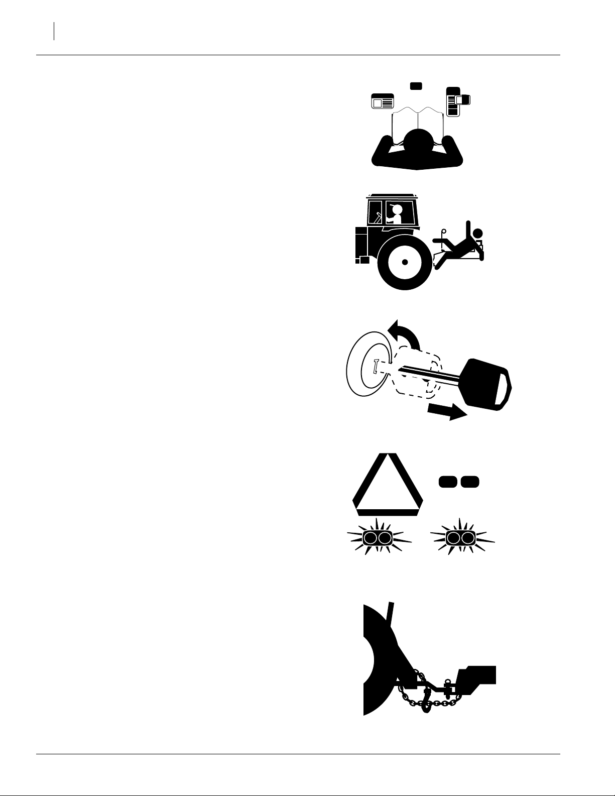
Be Familiar with Safety Decals
▲ Read and understand “Safety Decals,” thor-
oughly.
▲ Read all instructions noted on the decals.
Keep Riders Off Machinery
Riders obstruct the operator’s view. Riders could
be struck by foreign objects or thrown from the
machine.
▲ Never allow children to operate equipment.
▲ Keep all bystanders away from machine dur-
ing operation.
Shutdown and Storage
▲ Put tractor in park, turn off engine, and
remove the key.
▲ Secure implement using blocks and supports
provided.
OFF
▲ Detach and store implement in an area where
children normally do not play.
Use Safety Lights and Devices
Slow-moving tractors and towed implements can
create a hazard when driven on public roads.
They are difficult to see, especially at night.
▲ Use flashing warning lights and turn signals
whenever driving on public roads.
▲ Use lights and devices provided with imple-
ment.
Use A Safety Chain
▲ Use a safety chain to help control drawn
machinery should it separate from tractor
drawbar.
▲ Use a chain with a strength rating equal to or
greater than the gross weight of towed
machinery.
▲ Attach chain to tractor drawbar support or
other specified anchor location. Allow only
enough slack in chain to permit turning.
▲ Replace chain if any links or end fittings are
broken, stretched or damaged.
▲ Do not use safety chain for towing.
167-088Q-RUS 3/3/2006
Page 5
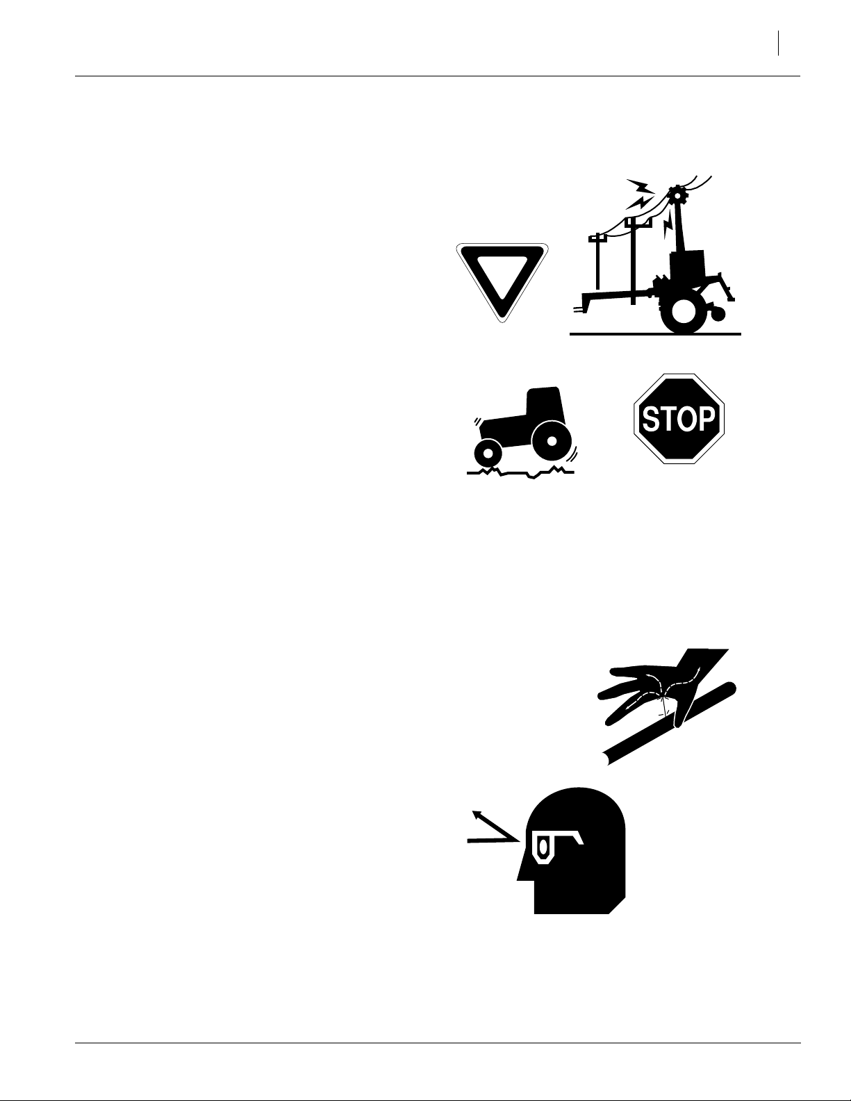
Transport Machinery Safely
Maximum transport speed for implement is 20
mph. Some rough terrains require a slower
speed. Sudden braking can cause a towed load to
swerve and upset.
▲ Do not exceed 20 mph. Never travel at a
speed which does not allow adequate control
of steering and stopping. Reduce speed if
towed load is not equipped with brakes.
▲ Comply with state and local laws.
▲ Do not tow an implement that, when fully
loaded, weighs more than 1.5 times the weight
of towing vehicle.
▲ Carry reflectors or flags to mark Front Fold
Boom Sprayer in case of breakdown on the
road.
Important Safety Information
3
▲ Keep clear of overhead power lines and other
obstructions when transporting. Refer to transport dimensions under “Specifications and
Capacities,” in the operator’s manual.
▲ Do not fold or unfold the implement while trac-
tor is moving.
Avoid High Pressure Fluids
Escaping fluid under pressure can penetrate the
skin, causing serious injury.
▲ Avoid the hazard by relieving pressure before
disconnecting hydraulic lines.
▲ Use a piece of paper or cardboard, NOT
BODY PARTS, to check for suspected leaks.
▲ Wear protective gloves and safety glasses or
goggles when working with hydraulic systems.
▲ If an accident occurs, see a doctor immedi-
ately. Any fluid injected into the skin must be
surgically removed within a few hours or gangrene may result.
3/3/2006
167-088Q-RUS
Page 6
ADC2220 & NTA 3510
4
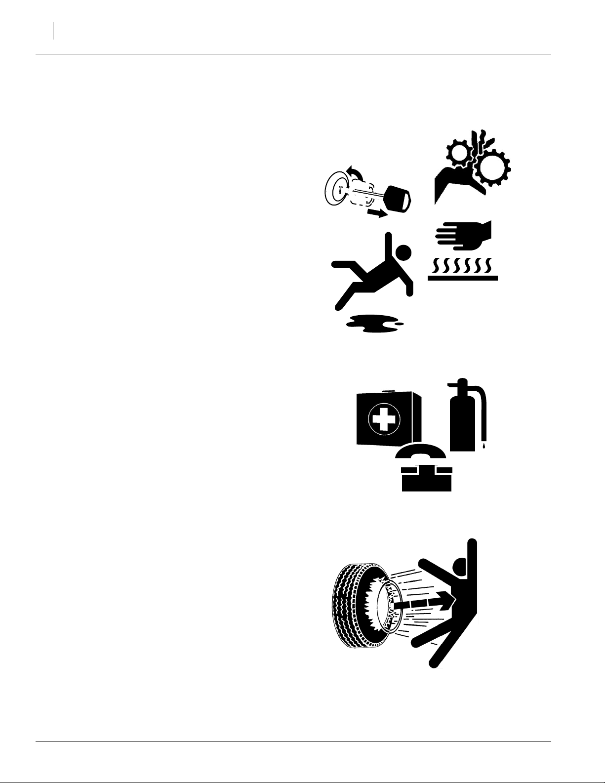
Practice Safe Maintenance
▲ Understand procedure before doing work. Use
proper tools and equipment. Refer to this manual for additional information.
▲ Work in a clean, dry area.
▲ Fold the implement, put tractor in park, turn off
engine, and remove key before performing
maintenance.
▲ Make sure all moving parts have stopped and
all system pressure is relieved.
▲ Allow the implement to cool completely.
▲ Disconnect battery ground cable (-) before
servicing or adjusting electrical systems or
before welding on the implement.
▲ Inspect all parts. Make sure parts are in good
condition and installed properly.
▲ Remove buildup of grease, oil or debris.
▲ Remove all tools and unused parts from the
implement before operation.
Prepare for Emergencies
▲ Be prepared if a fire starts.
▲ Keep a first aid kit and fire extinguisher handy.
OFF
▲ Keep emergency numbers for doctor, ambu-
lance, hospital and fire department near
phone.
Tire Safety
Tire changing can be dangerous and should be
performed by trained personnel using correct
tools and equipment.
▲ When inflating tires, use a clip-on chuck and
extension hose long enough for you to stand
to one side–not in front of or over tire assembly. Use a safety cage if available.
▲ When removing and installing wheels, use
wheel-handling equipment adequate for
weight involved.
911
167-088Q-RUS 3/3/2006
Page 7
Safety At All Times
Thoroughly read and understand the instructions
in this manual before operation. Read all instructions noted on the safety decals.
▲ Be familiar with all implement functions.
▲ Operate machinery from the driver’s seat only.
▲ Do not leave implement unattended with trac-
tor engine running.
▲ Do not dismount a moving tractor. Dismount-
ing a moving tractor could cause serious injury
or death.
▲ Do not stand between the tractor and imple-
ment during hitching.
▲ Keep hands, feet and clothing away from
power-driven parts.
Important Safety Information
5
▲ Wear snug-fitting clothing to avoid entangle-
ment with moving parts.
▲ Watch out for wires, trees, etc., when folding
and raising implement. Make sure all persons
are clear of working area.
▲ Do not turn tractor too tightly, causing imple-
ment to ride up on wheels. This could cause
personal injury or equipment damage.
3/3/2006
167-088Q-RUS
Page 8

ADC2220 & NTA 3510
6
Introduction
Great Plains welcomes you to its growing family
of new product owners. This Air Drill Cart and
this Air Drill Implement have been designed with
care and built by skilled workers using quality
materials. Proper setup, maintenance and safe
operating practices will help you get years of satisfactory use from the machine.
Description of Unit
The ADC2220 is a grain drill cart that uses air to
move seed or fertilizer from the cart bins to the
implement. Air is supplied by a fan driven by a
hydraulic motor. Pressurized meters under the
bins dispense material into the air stream at a
rate proportional to distance traveled. The meter
rate can be adjusted.
The NTA3510 is a seeding implement, with a
working width of 35 feet, designed to tow behind
a Great Plains air drill cart. This implement is designed for no-till field conditions. Coulters open a
narrow seedbed. Disk-type, parallel-linkage
openers follow each coulter, widening the seedbed and delivering seed to the trench.
Intended Usage
Use this cart with a Great Plains air drill implement. Use the cart for seeding small grains and
legumes or applying dry, granular fertilizer.
Models Covered
ADC2220, NTA 3510
IMPORTANT: A crucial point of information related to
the preceding topic. For safe and correct operation,
read and follow the directions provided before continuing.
Definitions
Right and left as used in this manual are determined by facing the direction the machine will
travel while in use unless otherwise stated.
NOTE: Useful information related to the preceding topic.
Assembly and Setup Assistance
To order additional copies of dealer assembly instructions or operator’s and parts manuals, write
to the following address. Include model numbers
in all correspondence.
If you do not understand any part of this manual
or have other assembly or setup questions, assistance is available. Contact
Product Support
Great Plains Mfg. Inc., Service Department
P.O. Box 5060
Salina, KS 67402-5060
Using This Manual
This manual was written to help you assemble
and prepare the new machine for the customer.
The manual includes instructions for assembly
and setup. Read this manual and follow the recommendations for safe, efficient and proper assembly and setup.
An operator’s manual is also provided with the
new machine. Read and understand “Important
Safety Information” and “Operating Instructions” in the operator’s manual before assem-
bling the machine. As a reference, keep the
operator’s manual on hand while assembling.
The information in this manual is current at printing. Some parts may change to assure top performance.
167-088Q-RUS 3/3/2006
Page 9

Before You Start
Read and understand the owners manual for your
implement. A basic understanding of how the drill
works will aid in the pre-assembly, assembly, setup and operation of your drill.
Perform these checks before setting up your
implement.
1. Read and understand “Important Safety Information,” beginning on page 1.
2. Check that all working parts are moving freely, bolts are tight, and cotter pins are spread.
3. Check that all grease fittings are in place and
lubricated.
Introduction
7
4. Check that all safety decals and reflectors are
correctly located and legible. Replace if damaged.
3/3/2006
167-088Q-RUS
Page 10
ADC2220 & NTA 3510
8
Pre-Assembly
The following headings are step-by-step instructions
for assembling the cart. Begin with Tools Required
and Pre-Assembly Checklist to make sure you have
all necessary parts and equipment. Then proceed
with Unload Center Section Rack. Follow each step to
make the job as quick and safe as possible and produce a properly working machine.
It is the dealer’s responsibility to unload the new machine. Unload all equipment before beginning assembly. Do not attempt any assembly work while the cart
is on the truck.
Tools Required
•
Forklift or overhead hoist with 8,000-pound capacity
• Hand jack with 4-ton capacity
• General hand tools
• Jack stands, blocks and safety chain
Pre-Assembly Checklist
1. Read and understand “Important Safety Information” on page 1 before assembling.
2. Have at least two people on hand while assembling.
3. Make sure the assembly area is level and free of
obstructions (preferably an open concrete area).
4. Have all major components.
5. Have all fasteners and pins shipped with cart.
Unload Center Section Rack
!
DANGER!
Crushing hazard. You may be severely injured or killed by
the cart if it falls. Secure cart to lifting equipment so it cannot fall. Do not walk or place any body part under the
raised sections of the cart.
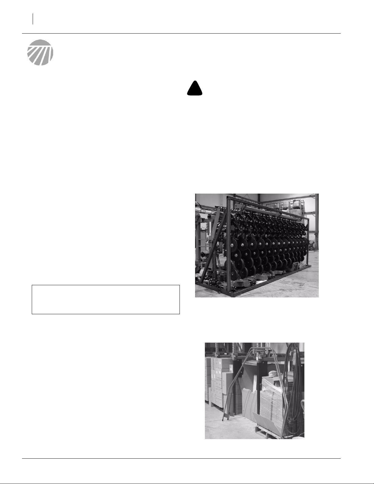
NOTE: The air drill cart and air drill implement are
shipped on racks via containers.There are three
racks total: the wing rack, the center section rack, and
the bins rack.
Refer to Figure 1
1. Unload the center section rack first. Remove as
many loose pieces as possible from rack. Keep
pieces separate.
IMPORTANT: If a pre-assembled part or fastener is
temporarily removed, remember where it goes. Keep
the parts separated.
6. Have a copy of the parts manual on hand. If unsure of proper placement or use of any part or
fastener, refer to the parts manual.
7. Check that all working parts are moving freely,
bolts are tight, and cotter pins are spread.
8. Check that all safety labels and reflectors are correctly located and legible. Replace if improperly
located or damaged. Refer to Safety Labels, “Im-
portant Safety Information” in the operator’s
manual.
9. Inflate tires to recommended pressure as listed
on the Tire Inflation Chart on the “Appendix” on
page 49. Tighten wheel bolts as specified on
Torque Values Chart on the “Appendix” on page
49.
167-088Q-RUS 3/3/2006
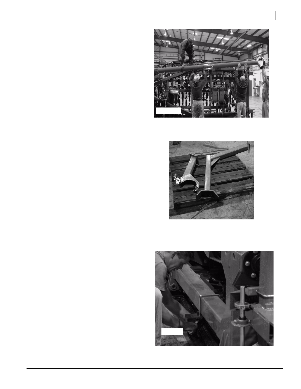
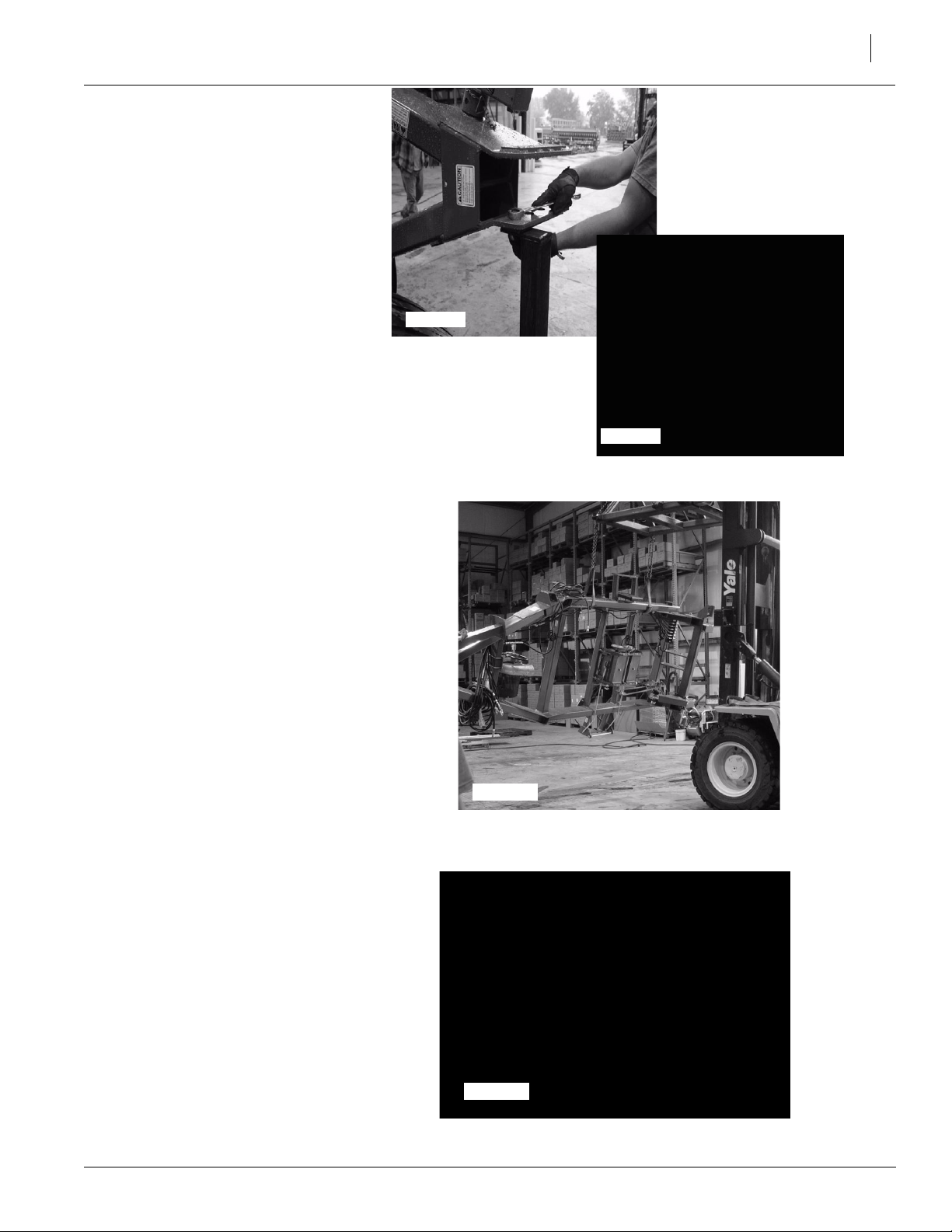
Refer to Figure 2
2. Unbolt walkboard rails from rack.
23492
Remove Walkboard Handrails
Figure 1
Center Section
Figure 2
23429
Page 11
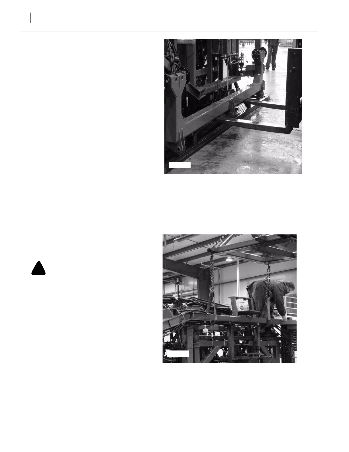
Refer to Figure 3
3. Unbolt and remove auger from rack.
23430
Figure 3
Detach Auger
Pre-Assembly
9
Refer to Figure 4
4. Unbolt and remove outer support arm
weldment and rear transport support from
ADC2220 frame in rack.
Refer to Figure 5
5. Detach rockshaft from rack by removing ubolts.
23437
Figure 4
Remove Support Weldments
3/3/2006
23436
Figure 5
Remove U-bolts
167-088Q-RUS
Page 12
ADC2220 & NTA 3510
10
Refer to Figure 6
6. Using forklift or other implement, remove
rockshaft from rack.
7. Unload remaining loose parts from rack.
Set parts aside for use later.
23431
Figure 6
Remove Rockshaft with Forklift
Refer to Figure 7
8. Attach lift straps to air drill cart frame. Unbolt air drill cart frame from rack. Use forklift
or other implement to lift drill from rack.
!
CAUTION!
Obey all safety instructions from lifting equipment
manufacturer. Be sure lift straps are securely attached prior to lifting. Be sure lifting equipment has
enough capacity to lift cart.
23441
Figure 7
Attach Lift Straps to ADC2220
Frame
167-088Q-RUS 3/3/2006
Page 13
Refer to Figure 8
9. Unscrew and remove all bolts securing ADC2220 frame to rack.
23432
23440
Figure 8
Remove Bolts
Pre-Assembly
11
Refer to Figure 9
10. Using forklift or other implement,
carefully raise ADC2220 frame from
rack.
Refer to Figure 10
NOTE: To finish assembling ADC2220
frame, two forklifts will be needed so
frame can be suspended horizontally
while tires are attached.
11. While frame is attached to forklift, secure opposite side of frame to another forklift using lift straps.
12. Using forklifts, level frame horizontally so tires may be attached.
23433
Figure 9
Remove Frame from Rack
23495
Figure 10
Level Frame
3/3/2006
167-088Q-RUS
Page 14
ADC2220 & NTA 3510
12
Cart Assembly
Drive Wheels
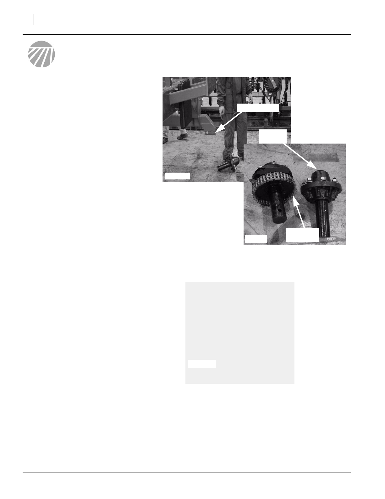
Refer to Figure 11
NOTE: The air drill cart tires come with two hub
assemblies - a drive hub assembly and a standard hub assembly. The drive hub assembly attaches to the right-hand side of the spindle tube.
The standard hub assembly attaches to the lefthand side of the spindle tube. Follow the instructions below to assemble hubs to spindle tube.
Spindle Tube
Hub
Assembly
23434
Refer to Figure 12
13. Unscrew and remove bolt in left-hand side of
spindle tube.
23442
Figure 11
Attach Hub Assembly to Spindle Tube
23493
Figure 12
Remove Bolt from Spindle Tube
Drive Hub
Assembly
167-088Q-RUS 3/3/2006
Page 15
Refer to Figure 13
14. Insert standard hub assembly into spindle tube align-
ing hole in hub assembly with hole in spindle tube.
15. Secure standard hub assembly to spindle tube with
bolt removed in step 1 on previous page.
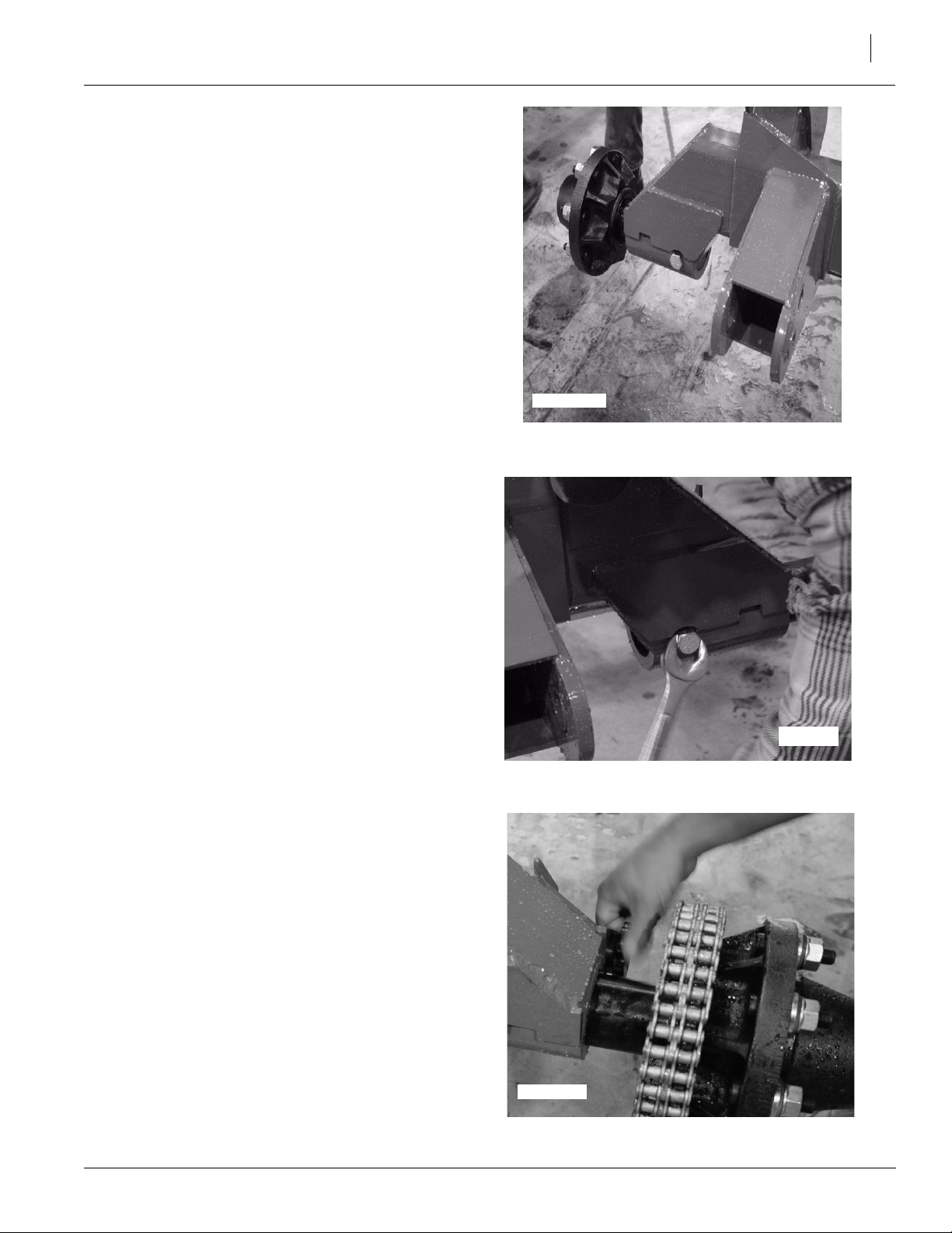
Refer to Figure 14
16. On opposite side of air drill cart frame, remove bolt
in spindle tube.
Cart Assembly
23435
Figure 13
Attach Standard Hub to Spindle Tube
13
Refer to Figure 15
17. Insert drive hub assembly into spindle tube aligning
hole in hub assembly with hole in spindle tube.
18. Secure drive hub assembly to spindle tube with bolt
removed in step 4 above.
23444
Figure 14
Remove Bolt from Spindle Tube
23446
Figure 15
Attach Drive Hub to Spindle Tube
3/3/2006
167-088Q-RUS
Page 16
ADC2220 & NTA 3510
14
Refer to Figure 16
19. Loosen sprocket on drive shaft located on right-hand
side of frame.
23494
Figure 16
Drive Shaft and Sprocket
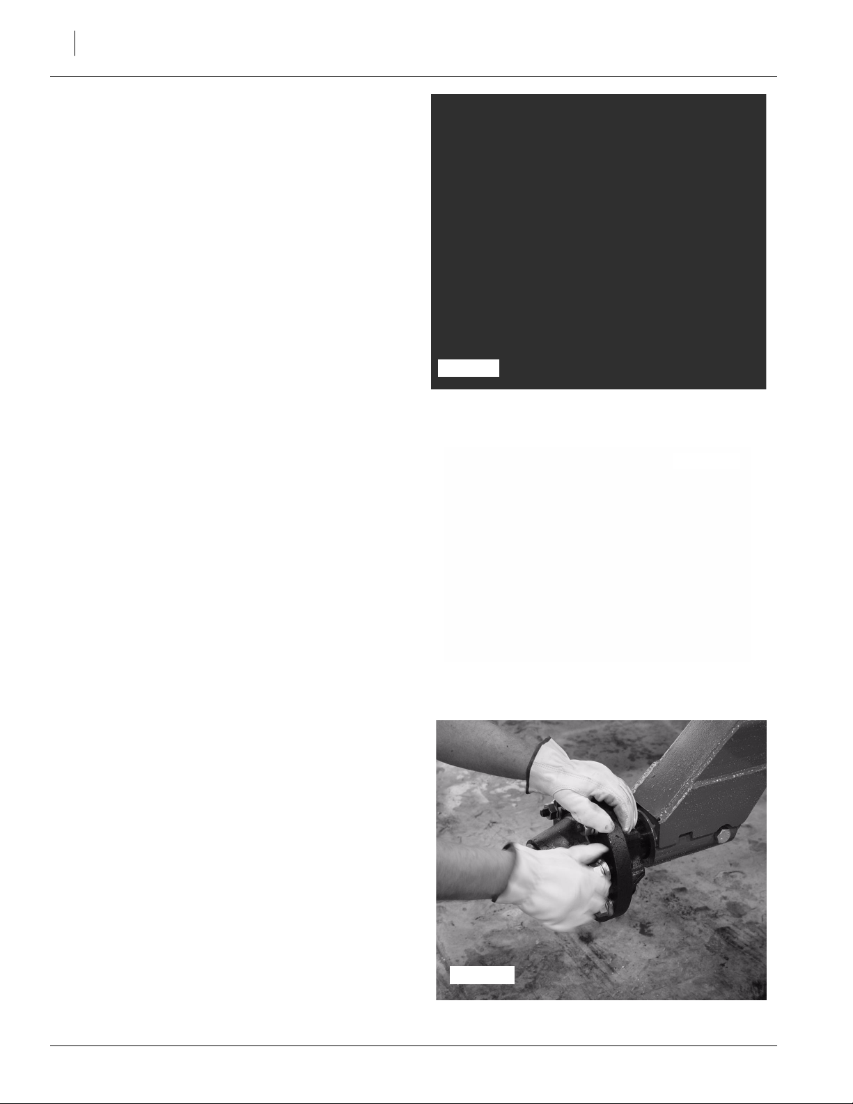
Refer to Figure 17
20. Adjust drive shaft, sprocket, and hub assembly so
when sprocket rotates it rotates chain as well.
NOTE: Make sure key is in sprocket on drive chain.
Refer to Figure 18
21. Remove all wheel nuts from hub assembly.
23447
Figure 17
Drive Shaft, Sprocket, and Hub Assembly
23445
Figure 18
Remove Wheel Nuts/Lug Nuts
167-088Q-RUS 3/3/2006
Page 17

Refer to Figure 19
22. Attach tire to hub assembly.
23. Using previously removed wheel nuts, secure tire to
hub assembly.
24. Tighten all wheel nuts.
25. Repeat steps 9 - 12 on opposite side of frame.
NOTE: Always check to make sure that tires are properly
inflated. Refer to Tire Inflation Chart on page 49.
Jack
Refer to Figure 20
1. Attach jack to frame. Use pin to secure jack to frame.
NOTE: At this point during setup, it is okay to remove lift
straps so that assembly may be completed.
Cart Assembly
Figure 19
Attach Tire to Frame
15
23438
Hitch Strap
Refer to Figure 21
1. Attach hitch strap to tongue. Align top hole of
hitch strap with 2nd hole from top in the frame.
Insert 1 1/4-7 X 11 bolt through frame and hitch.
Secure with washer and hex nut.
2. Insert 1 1/4-7 x 9 1/2 bolt, washer and safety
chain through 3rd hole from top in the frame and
bottom hole in the hitch. Secure with washer
and hex nut.
23439
Figure 20
Jack (in use)
23448
Figure 21
Hitch Strap
3/3/2006
167-088Q-RUS
Page 18

ADC2220 & NTA 3510
16
Engage/Disengage Levers
Refer to Figure 22
1. Remove flat washer and lock nut from bolt on clutch
linkage rod.
2. Secure linkage rod to lever with flat washer and lock
nut.
NOTE: Leave bolts secured loosely. Do NOT tighten
bolts down as levers will not function properly. Refer to
Figure 22.
Clutch Linkage Rod
Engage/Disengage Lever
23450
Unload Bins Rack
Refer to Figure 23
NOTE: The air drill cart and air drill implement are
shipped on racks via containers. There are three
racks total: the center section rack, the wing rack,
and the bins rack.
1. Unload all loose pieces from bins rack. Keep all
pieces separate. NOTE: DO NOT try to un-
load weight brackets from rack. A forklift
will be needed to unload brackets.
Clutch
Linkage
Rod
23045
Engage/Disengage
Lever
Figure 22
Engage/Disengage Levers
23049
Figure 23
Bin Rack
167-088Q-RUS 3/3/2006
Page 19

Refer to Figure 24
2. With use of a forklift or other implement, unload
weight brackets from bins rack.
23050
Cart Assembly
Figure 24
Unload Weight Brackets
17
Refer to Figure 25
3. Remove all parts, hoses, and bags from inside
the bins.
Refer to Figure 26
4. Attach lift straps to front bin. NOTE: This will
be the bin without the slow moving vehicle
decal.
23051
Figure 25
Inside of Bin
3/3/2006
23451
Figure 26
Attach Lift Straps
167-088Q-RUS
Page 20

ADC2220 & NTA 3510
18
Refer to Figure 27
5. Unscrew and remove all bolts securing bin to
the rack.
6. Using forklift or other implement, carefully
raise bin from rack.
23046
Figure 27
Remove Bolts
Refer to Figure 28
7. Once bin is removed from rack, carefully lower
bin on its side as shown in Figure 28. Remove
lift straps from forklift.
NOTE: Be careful when handling bins. To prevent damage, bins should be supported at all
times.
8. Gently maneuver bin to sit upright.
Refer to Figure 29
9. Reposition lift straps on bin so bin may be
raised with forklift as shown in Figure 29.
10. Raise bin from ground using forklift.
23453
Figure 28
Bin
23454
Figure 29
Front Bin
167-088Q-RUS 3/3/2006
Page 21

Refer to Figure 30
11. Place front bin (1) on air drill cart frame. Make
sure front of the bin (1) is toward front of frame
(2). NOTE: The flat side of the front bin is
the back.
Cart Assembly
19
Refer to Figure 31
12. Align holes in bottom of bin with holes in frame
so bin can secure to frame with bolts.
23057
Figure 30
Front Bin to Frame
Figure 31
Align Box and Frame
23047
Refer to Figure 32
13. Secure the bin to the air drill cart frame using
hardware located in bags attached to the
frame.
3/3/2006
23048
Figure 32
Bag of Hardware
167-088Q-RUS
Page 22

ADC2220 & NTA 3510
20
Refer to Figure 33
14. Attach lift straps to rear bin. NOTE: This will
be the bin with the slow moving vehicle decal.
15. Unscrew and remove all bolts securing rear
bin to rack.
16. Using forklift or other implement, carefully remove rear bin from rack.
Refer to Figure 34
17. Once bin is removed from rack, carefully
lower bin to ground. Remove lift straps from
bin.
NOTE: Be careful when handling bins. To
prevent damage, bins should be supported
at all times.
18. Reposition lift straps on bin so bin may be
raised with forklift as shown in Figure 34.
19. Raise bin from ground using forklift.
23058
Figure 33
Attach Lift Straps to Rear Bin
Refer to Figure 35
20. Place rear bin (1) on air drill cart frame. Make
sure front of the bin (1) is toward front of frame
(2). NOTE: The flat side of the rear bin is
the front.
23059
Figure 34
Rear Bin
23061
Figure 35
Rear Bin to Frame
167-088Q-RUS 3/3/2006
Page 23

Refer to Figure 36
21. Align holes in bottom of bin with holes in frame
so bin can secure to frame with bolts.
Refer to Figure 37
22. Secure bin to air drill cart frame using hardware located in bags attached to the frame.
Meterboxes
Refer to Figure 38
1. Place a thin bead of silicon around the top
edge of one meterbox (1). Attach meterbox (1)
to front bin with flared outlets toward the back.
2. Use vise grips to hold meterbox (1) to bin. Se-
cure box (1) to bin using bolts (4), washers (2),
and nuts (3).
3. Repeat steps 1-2 to attach second meterbox
to rear bin.
23061
23048
Cart Assembly
Figure 36
Align Rear Bin to Frame
Figure 37
Bag of Hardware
21
3/3/2006
Front Bin
NOTE: ADC2220 frame is removed for clarity.
Figure 38
Meter Boxes
Rear Bin
23460
167-088Q-RUS
Page 24

ADC2220 & NTA 3510
22
Fan and Fan Outlet Transition
Refer to Figure 39
1. Remove set screws from fan. Keep set screws
for reuse.
Refer to Figure 40
2. Attach fan outlet transition to fan as shown in
Figure 40.
3. Secure fan outlet transition to fan with set
screws removed in step 1.
23053
Figure 39
Remove Set Screws
23064
Figure 40
Attach Fan to Fan Outlet Transition
Refer to Figure 41
4. Remove bolt from fan.
5. Attach fan outlet transition to fan.
23065
Figure 41
Attach Fan to Fan Outlet Transition
167-088Q-RUS 3/3/2006
Page 25

Refer to Figure 42
6. Secure transition to fan with previously removed bolt.
Refer to Figure 43
7. Attach hoses from fan outlet transition (5) to
front meterbox (1) inlets. Secure with hose
clamps (3).
8. Using hose clamps (3), attach hose (4) from
front (1) meterbox outlets to rear meterbox (2)
inlets.
9. Secure hose (4) on rear meterbox (2) inltets
with hose clamps (3).
2306623066
Figure 42
Fan
Cart Assembly
23
Auger Support Weldments
Refer to Figure 44
1. Attach auger front storage support arm (2) to
mounting plate (1) located on the frame. Use
bolts (3) to secure arm (2) to plate (1).
2. Attach inner support arm (6) to frame using
inner support arm shaft (4). Secure inner
support arm shaft with bolt (5) and lock nut.
3. Insert outer pivot shaft tube into outer support arm weldement (7). Secure outer arm to
inner support arm (6) using bolt (8), lock
washer, and hex nut.
4. Insert auger swivel support (11) through two
flat washers (9), outer support arm weldment
(7), and a flat washer (9). Secure with pin roll
(10).
23449
Figure 43
Fan Hose with Clamps
3/3/2006
Figure 44
Install Auger Support Weldments
23459
167-088Q-RUS
Page 26

ADC2220 & NTA 3510
24
Auger
Refer to Figure 45
1. Attach auger (1) to auger swivel
support (2).
2. Insert bolt and flat washer
through holes in auger (1) and
secure with flat washer, lock
washer, and hex nut.
23458
Figure 45
Install Auger
Refer to Figure 46
3. Secure auger hopper to auger
using bolts, flat washer, and lock
washer.
Refer to Figure 47
4. Attach auger strap handle to auger
hopper.
23457
Figure 46
Auger Hopper and Auger
23260
Figure 47
Auger Strap Handle
167-088Q-RUS 3/3/2006
Page 27

Chains
Refer to Figure 48
1. Unwrap and route chain from front gearbox
to front meterbox as shown in Figure 48.
NOTE: Chain will wrap the same from rear
gearbox to rear meterbox.
Gearbox Levers
Refer to Figure 49
1. Slide gearbox levers (3) through holes in
mounting plate (2).
2. Attach levers (3) to gearboxes as shown.
Secure with cotter pin (1).
23496
Figure 48
Chain Routing
Cart Assembly
25
Walkboard
Refer to Figure 50
1. Attach walkboard handrail to rear bin using
bolts (2) and flat washers (3).
2. Secure handrail using flat washers (4) and
lock nuts (5).
3. Attach other walkboard handrail to rear of
front bin using steps 1 and 2 above.
3/3/2006
23497
23443
Figure 49
GearboxLevers
Figure 50
Handrail Assembly
167-088Q-RUS
Page 28

ADC2220 & NTA 3510
26
Refer to Figure 51
4. Attach upper ladder mount (2) to
bins using bolts (10), flat washers (4), lock washers (5), and
hex nuts (6).
5. Place upper ladder weldment (3)
on mount (2). Secure weldment
(3) to mount (2) and handrails (1)
using bolts (7), lock washers (9)
and hex nuts (8).
NOTE: Front bin removed for clarity.
Refer to Figure 52
6. Attach walkboard (1) to upper
ladder mount (2).
7. Secure walkboard (1) to mount
(2) with bolts (4), 3-point step
retainers (3), lock washers (5),
and hex nuts (6).
23068
Figure 51
Upper Ladder Mount and Weldment
23498
Figure 52
Walkboard
167-088Q-RUS 3/3/2006
Page 29

Bins
Refer to Figures 53 and 54
1. Plastic tubes should be installed inside the
bins - two per bin.
2. Install plastic tubes from rear of bin to rear
of metering device in front bin.
3. Install plastic tubes from front of bin to rear
of metering device in rear bin.
NOTE: It is important that the plastic tubes are
installed properly to equalize air pressure. If
they are not installed correctly, the implement
may produce undesirable results.
Metering
Device
Cart Assembly
Front
Rear
Figure 53
View of Front Hopper from Above
27
23257
Bin Lids
Refer to Figure 55
1. Place bin lid on top of bin. Bin lid hinge will
bolt to bin on opposite side across from ubolt.
2. Attach bin lid to top of bin using bolts and
flat washers.
3. Secure lid with flat washers and lock nuts.
4. Repeat steps 1-3 to attach second bin lid to
other bin.
23256
Front
Metering
Rear
Figure 54
View of Rear Hopper from Above
Device
23070
3/3/2006
Figure 55
Bin Lid
167-088Q-RUS
Page 30

ADC2220 & NTA 3510
28
Hose Guide Attachment
Refer to Figure 56
1. Secure hose guide attachment to tongue of air
drill cart with bolt.
23067
Figure 56
Hose Guide Attachment
167-088Q-RUS 3/3/2006
Page 31

Implement Assembly
Center Section Frame
Refer to Figure 57
NOTE: The air drill implement comes shipped in
racks via containers. There are two racks; the
center section rack and the wings rack. The center section of the implement will need to be unloaded first.
Refer to Figure 58
2. Remove all sections of the rack obstructing
center section removal from rack.
23499
Implement Assembly
Figure 57
Center Section Rack
29
Refer to Figure 59
3. Loosen u-bolts securing center section
frame to rack.
IMPORTANT: DO NOT completely remove ubolts securing frame to rack. This will be done
once the lift straps have been attached to frame.
3/3/2006
24102
Figure 58
Remove Bolts
24103
Figure 59
Loosen U-bolts
167-088Q-RUS
Page 32

ADC2220 & NTA 3510
30
Refer to Figure 60
NOTE: Hydraulic cylinders need to be secured to
frame before removing frame from rack. Secure
cylinders with bungee strap or tie-down strap.
Refer to Figure 61
4. Remove both wing pivot pin weldments from
frame. Pins are located in frame at top of
rack. NOTE: Keep pins and hardware for reuse.
24104
Figure 60
Secure Hydraulic Cylinders to Frame
Refer to Figure 62
5. Attach lift straps to center section frame.
!
CAUTION!
Obey all safety instructions from lifting equipment
manufacturer. Be sure lift straps are securely attached
prior to lifting. Be sure lifting equipment has enough
capacity to lift implement.
6. Completely remove u-bolts securing frame to
rack.
7. Using forklift or other implement, carefully lift
center section frame from rack.
24105
Figure 61
Remove Pivot Pin from Frame
24106
Figure 62
Attach Lift Straps and Lift Frame from Rack
167-088Q-RUS 3/3/2006
Page 33

Refer to Figures 63 and 64
8. With help of second forklift,level center section frame. Frame should sit upright resting
gently on press wheels.
Figure 63
Lowering Frame
Implement Assembly
24107
31
Refer to Figure 65
NOTE: Be sure frame sits upright as shown in Figure 65. Do not detach lift straps from frame. Lift
straps will be detached later in assembling process.
24108
Figure 64
Righting Frame
24109
Figure 65
Center Section Frame
3/3/2006
167-088Q-RUS
Page 34

ADC2220 & NTA 3510
32
Coulter Blades
Refer to Figure 66
9. Attach coulter blade to coulter hub assembly
using bolts
.
NOTE: If attaching turbo coulter blades, blades
m
ust attach properly with rotation arrow pointing
toward direction of travel.
10. Attach remaining blades to coulter hub assemblies.
24110
23343
Figure 66
Attach Coulter Blades
Parallel Arm Lift Assembly
Refer to Figure 67
11. Using forklift, remove parallel arm lift assembly from rack.
24111
Figure 67
Remove Parallel Arms from Rack
167-088Q-RUS 3/3/2006
Page 35

Refer to Figure 68
12. Remove bolts and hardware from parallel arm
lift assembly.
Refer to Figure 69
13. Loosen bolt on pivot bolt holder. NOTE: Holder should be loose enough to move freely.
Implement Assembly
24113
Figure 68
Remove Bolts from Parallel Arms Assembly
33
24112
24114
Figure 69
Loosen Pivot Bolt Holder
3/3/2006
167-088Q-RUS
Page 36

ADC2220 & NTA 3510
34
Refer to Figure 70
14. Align parallel arm assembly with frame. Top
set of parallel arms align with top hole of frame
and pivot bolt holder. NOTE: Make sure to bolt
parallel arm assembly to frame with eyebolt
weldment on top.
Refer to Figure 71
15. Insert bolt removed in step 11 through pivot
bolt holder, frame, and parallel arm lift assembly.
16. Secure with hardware removed in step 11.
17. Repeat steps for installing parallel arm lift assembly on opposite side of the implement.
Frame
Parallel Arms
24138
Figure 70
Align Parallel Arms with Frame
24115
Parallel Arm Dual Gauge Wheels
Refer to Figure 72
1. Remove tape from gauge wheel.
2. Remove caster retainer cap and pivot thrust
washer from gauge wheel.
24116
Figure 71
Bolt Parallel Arms to Frame
24117
Figure 72
Gauge Wheel
167-088Q-RUS 3/3/2006
Page 37

Refer to Figure 73
3. Slide pivot thrust washers down shaft of
gauge wheel.
4. Attach gauge wheel to parallel arm lift assembly by sliding gauge up through assembly.
Refer to Figure 74
5. Place caster retainer cap on top of gauge
wheel.
6. Secure caster retainer cap to gauge wheel using bolt and lock washer.
7. Repeat steps to install gauge wheel on opposite side of implement.
Implement Assembly
Figure 73
Gauge Wheel
35
24118
Parallel Arm Gauge Wheel Hydraulics
Refer to Figure 75
1. Remove hydraulic cylinder that is secured to
fr
ame via bungee cord or tie-down strap.
NOTE: Use the cylinder closest to the
gauge wheel each gauge wheel.
2. Remove pin, washer, and cotter pin from base
end of hydraulic cylinder.
3. Align base end of hydraulic cylinder with
frame.
4. Insert pin through cylinder and frame.
5. Slide washer on pin and secure with cotter
pin.
24119
Figure 74
Secure Gauge Wheel and Caster Retainer Cap
24120
Figure 75
Gauge Wheel Hydraulic Cylinders
3/3/2006
167-088Q-RUS
Page 38

ADC2220 & NTA 3510
36
Refer to Figure 76
6. Using pin, pull rod end of cylinder until cylinder can be secured to eyebolt weldment.
7. Once hydraulic cylinder and eyebolt weldment
are aligned, insert pin completely.
8. Slide washer on pin and secure with cotter
pin.
9. Complete previous steps on opposite side of
implement to attach hydraulic cylinder to
gauge wheel.
Dual Gauge Wheel Tires
Refer to Figure 77
10. Reattach lift straps to implement frame and
raise frame so that gauge wheel tires can be
installed.
11. Remove wheel nuts from gauge wheel hub
assembly.
12. Attach gauge wheel tire to gauge wheel hub.
13. Secure tire to hub with previously removed
wheel nuts.
14. Repeat process on second tire on gauge
wheel.
15. Complete steps 10-14 to install gauge
wheels on opposite side of implement.
24121
Figure 76
Gauge Wheel Hydraulic Cylinder
24140
Figure 77
Attach Gauge Wheel Tires
24139
Rockshaft
Refer to Figure 78
NOTE: Rockshaft installs on opposite
side of center frame from dual guage
wheels.
1. Align rockshaft with holes in center
frame.
24122
167-088Q-RUS 3/3/2006
Figure 78
Attach Rockshaft
Page 39

Refer to Figure 79
2. Once rockshaft is aligned with frame, insert
pins through frame and rockshaft.
3. Secure pins with pin rolls.
Refer to Figure 80
4. Attach hydraulic cylinder to rockshaft.
5. Secure cylinder to rockshaft with pin. Slide
washer over pin and secure with cotter pin.
6. Complete steps 4 and 5 to attach remaining
hydraulic cylinders to rockshaft.
Implement Assembly
Figure 79
Secure Rockshaft to Frame
37
24123
Rockshaft Gauge Wheel Tires
Refer to Figure 81
1. Remove wheel nuts from gauge wheel hub
assembly.
2. Attach gauge wheel tire to gauge wheel hub.
3. Secure tire to hub with previously removed
wheel nuts.
4. Repeat process on second tire on gauge
wheel.
5. Complete steps 1-4 to install guage wheels
on opposite side of rockshaft.
24124
Figure 80
Attach Hydraulic Cylinder to Rockshaft
24141
Figure 81
Attach Gauge Wheel Tires to Rockshaft
3/3/2006
167-088Q-RUS
Page 40

ADC2220 & NTA 3510
38
Left Wing Frame
Refer to Figure 82
1. Attach lift straps to the left wing frame in the
rack.
!
CAUTION!
Obey all safety instructions from lifting equipment
manufacturer. Be sure lift straps are securely attached prior to lifting. Be sure lifting equipment has
enough capacity to lift implement.
2. Unscrew and remove all bolts securing left
wing frame to rack.
3. Using a forklift or other implement, remove
left wing frame from rack.
Refer to Figure 83
4. Carefully lower wing frame onto ground. Remove lift straps. Replace straps so frame
can be lifted in position.
5. Align left wing frame and center section
frame.
24125
Figure 82
Attach Lift Straps to Left Wing Frame
Refer to Figures 84 and 85
6. Secure wing frame to center section in both
front (figure 84 ) and back (figure 85) of implement with pin.
24128
Figure 84
Secure Wing Frame to Center Frame
(Front of Implement)
24126
Figure 83
Align Frame
24127
Figure 85
Secure Wing Frame to Center Frame
(Back of Frame)
167-088Q-RUS 3/3/2006
Page 41

Gauge Wheels
Refer to Figure 86
1. Attach gauge wheel arm to backside of left
wing frame.
2. Secure gauge wheel arm to frame using
wing pivot pin (2) and pin roll (1).
Refer to Figure 87
3. Remove tie-down strap and hydraulic cylinder from frame.
4. Attach base end of gauge wheel hydraulic
cylinder to eyebolt weldment on gauge
wheel.
5. Secure rod end of hydraulic cylinder to
gauge wheel arm using pin and cotter pin.
Implement Assembly
Figure 86
Attach Gauge Wheel Arm
39
24142
Refer to Figure 88
6. Attach gauge wheel tire (1) to gauge wheel
hub assembly (2). Secure tire to hub with
wheel nuts.
7. Repeat step 6 to install gauge wheel tire on
other side of gauge wheel arm.
3/3/2006
24144
Figure 87
Attach Hydraulic Cylinder
24143
Figure 88
Gauge Wheel Tires
167-088Q-RUS
Page 42

ADC2220 & NTA 3510
40
Coulter Blades
Refer to Figure 89
1. Attach coulter blade to coulter hub assembly using bolts.
NOTE: If attaching turbo coulter blades,
blades must attach properly with rotation arrow pointing toward direction of travel.
2. Attach remaining blades to coulter hub assemblies.
24110
23343
Figure 89
Coulter Blades
Right Wing Frame
Coulter Blade Arms
Refer to Figure 90
NOTE: On the right wing frame, for shipping purposes, the coulter blade arms were turned to the
side. Coulter blade arms will need to be turned
back to the correct position.
Refer to Figure 91
1. Loosen back bolt of coulter arm with a
wrench.
2. Turn coulter blade arm to correct position.
Arm should be positioned straight out from
frame, not to the side.
24147
Figure 90
Coulter Blade Arm
24148
Figure 91
Loosen Back Bolt
167-088Q-RUS 3/3/2006
Page 43

Refer to Figure 92
3. Secure coulter arm in position with bolt and
nut.
Frame
Refer to Figure 93
1. Attach lift straps to the right wing frame in
the rack.
24149
Figure 92
Secure Arm
Implement Assembly
41
!
CAUTION!
Obey all safety instructions from lifting equipment
manufacturer. Be sure lift straps are securely attached prior to lifting. Be sure lifting equipment has
enough capacity to lift implement.
2. Unscrew and remove all bolts securing right
wing frame to rack.
3. Using a forklift or other implement, remove
right wing frame from rack.
Refer to Figure 94
4. Carefully lower wing frame onto blocks or
stands. Remove lift straps. Replace straps
so frame can be lifted in position.
5. Align right wing frame and center section
frame.
24145
Figure 93
Right Wing Frame
3/3/2006
24146
Figure 94
Righting Frame
167-088Q-RUS
Page 44

ADC2220 & NTA 3510
42
Refer to Figures 95
6. Secure wing frame to center section in both
front and back of implement with pin.
Right Wing
Frame
Pin
24150
Gauge Wheels
Refer to Figure 96
1. Attach gauge wheel arm to backside of right
wing frame.
2. Secure gauge wheel arm to frame using
wing pivot pin (2) and pin roll (1).
Pin
Center Section
Frame
Figure 95
Attach Wing to Center
24151
Figure 96
Attach Gauge Wheels
167-088Q-RUS 3/3/2006
Page 45

Refer to Figure 97
3. Remove tie-down strap and hydraulic cylinder
from frame.
4. Attach base end of gauge wheel hydraulic cylinder to eyebolt weldment on gauge wheel.
5. Secure rod end of hydraulic cylinder to gauge
wheel arm using pin and cotter pin.
Refer to Figure 98
6. Attach gauge wheel tire (1) to gauge wheel
hub assembly (2). Secure tire to hub with
wheel nuts.
7. Repeat step 6 to install gauge wheel tire on
other side of gauge wheel arm.
Implement Assembly
24152
Figure 97
Gauge Wheel Hydraulic Cylinder
43
Coulter Blades
Refer to Figure 99
1. Attach coulter blade to coulter hub assembly using bolts.
NOTE: If attaching turbo coulter blades,
blades must attach properly with rotation arrow pointing toward direction of travel.
2. Attach remaining blades to coulter hub assemblies.
24143
Figure 98
Attach Gauge Wheel Tires
24110
23343
3/3/2006
Figure 99
Coulter Blades
167-088Q-RUS
Page 46

ADC2220 & NTA 3510
44
Lights
Refer to Figures 100 and 101
1. Insert lights in to light bracket. Red light
needs placed on inside closest to center of
frame. Place amber light on outside farthest away from center of frame.
2. Connect lights to light harness.
24153
Figure 100
Insert Lights into Light Bracket
Openers and Press Wheels
Refer to Figure 102
1. Locate all openers to be attached to righthand side wing frame.
To Center of
Frame
24154
To Wing
Frame
Figure 101
Lights
24183
Figure 102
Openers
167-088Q-RUS 3/3/2006
Page 47

Refer to Figure 103
2. Stagger openers on wing frame as shown.
3. Secure each opener to frame and parallel
opener mount plate with a 5/8” bolt through top
hole of opener and opener mount plate.
4. Secure opener to frame and parallel opener
mount plate with a 5/8” u-bolt through the bottom holes of opener and opener and mount
plate.
5. Secure bolt and u-bolt with 5/8” lock washer
and 5/8” hex nut.
6. Repeat steps 2-5 to install openers.
24184
Figure 103
Openers on Frame
Implement Assembly
45
Refer to Figure 104
7. Insert pin roll (2) into press wheel arm adjustment handle (1).
8. Place press wheel arm adjustment handle (1)
down through opener. From underneath opener, attach opener trunion (4) to press wheel arm
adjustment handle (1). Secure with spring (3)
and pin clevis (5).
24155
24156
Figure 104
Press Wheel Arm Adjustment Handle
3/3/2006
167-088Q-RUS
Page 48

ADC2220 & NTA 3510
46
Refer to Figure 105
9. If not already attached, attach press
wheel (8) to press wheel arm (5) with
bolt (7) and lock washer (6).
10. Insert press wheel arm pivot tube (3)
and parallel arm pivot bushings (4) into
parallel arm (5).
11. Secure parallel arm (5) to opener body
with bolt (1) and hex nut (2).
12. Complete steps 9-11 for all press
wheels.
Air Towers
Refer to Figure 106
NOTE: On the NTA3510 frame there are several white markings. These markings indicate air tower placement.
24185
Figure 105
Press Wheel
24157
Figure 106
Marking for Air Tower
Refer to Figure 107
1. Attach air tower to NTA3510 frame
where indicated by white markings.
24158
Figure 107
Air Tower
167-088Q-RUS 3/3/2006
Page 49

Refer to Figure 108
2. Secure air tower to frame using u-bolt and hardware.
Refer to Figure 109
3. Attach 1 inch seed hoses from top of air tower to
openers.
4. Attach 2 1/2 seed hose to bottom of air tower. Secure with hose clamp.
Implement Assembly
Figure 108
Securing Air Tower
47
24159
Folding Hydraulic Cylinder
Refer to Figure 110
1. Attach folding hydraulic cylinder (2) to arm on
wing frame.
2. Insert bushing (1) through cylinder (2) and arm.
3. Secure hydraulic cylinder (2) to arm on wing
frame. Use pin clevis (5), flat washer (3), and cotter pin (4).
24186
Figure 109
Air Tower Hoses
3/3/2006
24160
Figure 110
Hydraulic Cylinder
167-088Q-RUS
Page 50

ADC2220 & NTA 3510
48
Cart Hook-Up
Refer to Figure 111
1. Attach one cart link weldment (5) to NTA3510
frame. Use cart link pin (1) and pin roll (2) to secure.
2. Attach the other cart link weldment (5) to
NTA3510 frame. Use cart link pin (1) and pin roll
(2) to secure.
To attach ADC2220 to NTA3510:
1. Attach center of cart to cart link weldment (5) using bushing spindles (3), center cart link pin (4),
and pin roll (2).
2. Attach each end of cart to cart link weldment (5)
using bushing spindles (3), cart link pin (1), and
pin roll (2).
Air Drill Cart
Frame
24173
Figure 111
Cart Hook-Up
167-088Q-RUS 3/3/2006
NTA3510
Frame
Page 51

Appendix
Torque Values Chart for Common Bolt Sizes
Appendix
49
Bolt Head Identification
Bolt Size
(Inches)
1
in-tpi
1/4" - 20 7.4 5.6 11 8 16 12 M 5 X 0.8 436597
1/4" - 28 8.5 6 13 10 18 14 M 6 X 1 7 5 11 8 15 11
5/16 - 18 15 11 24 17 33 25 M 8 X 1.25 17 12 26 19 36 27
5/16" - 24 17 13 26 19 37 27 M 8 X 1 18 13 28 21 39 29
3/8" - 16 27 20 42 31 59 44 M10 X 1.5 33 24 52 39 72 53
3/8" - 24 31 22 47 35 67 49 M10 X 0.75 39 29 61 45 85 62
7/16" - 14 43 32 67 49 95 70 M12 X 1.75 58 42 91 67 125 93
7/16" - 20 49 36 75 55 105 78 M12 X 1.5 60 44 95 70 130 97
1/2" - 13 66 49 105 76 145 105 M12 X 1 90 66 105 77 145 105
1/2" - 20 75 55 115 85 165 120 M14 X 2 92 68 145 105 200 150
9/16" - 12 95 70 150 110 210 155 M14 X 1.5 99 73 155 115 215 160
9/16" - 18 105 79 165 120 235 170 M16 X 2 145 105 225 165 315 230
5/8" - 11 130 97 205 150 285 210 M16 X 1.5 155 115 240 180 335 245
5/8" - 18 150 110 230 170 325 240 M18 X 2.5 195 145 310 230 405 300
3/4" - 10 235 170 360 265 510 375 M18 X 1.5 220 165 350 260 485 355
3/4" - 16 260 190 405 295 570 420 M20 X 2.5 280 205 440 325 610 450
7/8" - 9 225 165 585 430 820 605 M20 X 1.5 310 230 650 480 900 665
7/8" - 14 250 185 640 475 905 670 M24 X 3 480 355 760 560 1050 780
1" - 8 340 250 875 645 1230 910 M24 X 2 525 390 830 610 1150 845
1" - 12 370 275 955 705 1350 995 M30 X 3.5 960 705 1510 1120 2100 1550
1-1/8" - 7 480 355 1080 795 1750 1290 M30 X 2 1060 785 1680 1240 2320 1710
1 1/8" - 12 540 395 1210 890 1960 1440 M36 X 3.5 1730 1270 2650 1950 3660 2700
1 1/4" - 7 680 500 1520 1120 2460 1820 M36 X 2 1880 1380 2960 2190 4100 3220
1 1/4" - 12 750 555 1680 1240 2730 2010
1 3/8" - 6 890 655 1990 1470 3230 2380
1 3/8" - 12 1010 745 2270 1670 3680 2710
1 1/2" - 6 1180 870 2640 1950 4290 3160
1 1/2" - 12 1330 980 2970 2190 4820 3560
Torque tolerance + 0%, -15% of torquing values. Unless otherwise specified use torque values listed above.
Grade 2 Grade 5
N · m2ft-lb3N · m ft-lb N · m ft-lb mm x pitch4N · m ft-lb N · m ft-lb N · m ft-lb
Grade 8
Bolt Size
(Metric)
1
in-tpi = nominal thread dia.in inches-threads per inch
2
N· m = newton-meters
3
ft-lb= foot pounds
4
mm x pitch = nominal thread dia. in millimeters x thread pitch
Bolt Head Identification
5.8 8.8 10.9
Class 5.8 Class 8.8 Class 10.9
Tire Inflation Chart
Tire Size Inflation PSI Tire Size Inflation PSI
7.50 x 20" 4-Ply Drill Rib 28 11L x 15" 6-Ply Rib Implement 28
9.0 x 22.5 10-Ply Highway Service 70 70 11L x 15" 12-Ply Rib Implement 52
9.0 x 24" 8-Ply Rib Implement 40 12.5L x 15" 8-Ply Rib Implement 36
9.5L x 15" 6-Ply Rib Implement 32 12.5L x 15" 10-Ply Rib Implement 44
9.5L x 15" 8-Ply Rib Implement 44 16.5L x 16.1" 10-Ply Rib Implement 36
9.5L x 15" 12-Ply Rib Implement 60 21.5 x 16.1” SC 10-Ply Rib Implement 28
3/3/2006
167-088Q-RUS
Page 52

Great Plains Manufacturing, Inc.
Corporate Office: PO. Box 5060
Salina, Kansas 67402-5060 USA
 Loading...