

Page 1
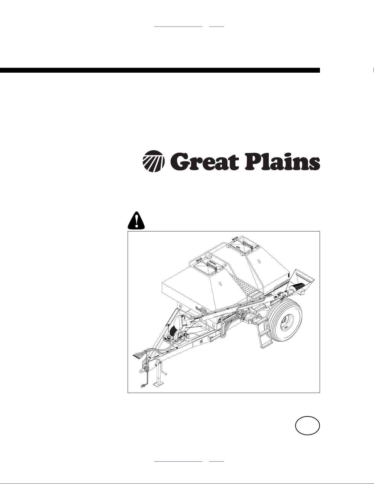
Table of Contents Index
Operator Manual
ADC2220
Air Drill Cart
Manufacturing, Inc.
www.greatplainsmfg.com
Read the operator manual entirely. When you see this symbol, the
subsequent instructions and warnings are serious - follow without
exception. Your life and the lives of others depend on it!
16263
Illustrations may show optional equipment not supplied with standard unit, may depict
an ADC1150 or ADC2350/B model where a topic is identical, and may depict any of
several air drill implements.
ORIGINAL INSTRUCTIONS
© Copyright 2012 Printed 2012-10-17 167-073M
Table of Contents Index
EN
Page 2

Table of Contents Index
Table of Contents Index
Page 3

Great Plains Manufacturing, Inc. Cover Index iii
Table of Contents
Important Safety Information ......................................1
Safety Decals .................................................................6
Introduction ................................................................12
Air Cart Document Family ............................................12
Description of Unit ........................................................ 12
Intended Usage ........................................................12
Using This Manual........................................................12
Definitions................................................................. 12
Owner Assistance ........................................................13
Preparation and Setup ............................................... 14
Initial Setup...................................................................14
Pre-Setup Checklist......................................................14
Hitching ........................................................................14
Hitching Air Cart to Tractor.......................................15
Make Electrical Connections ....................................15
Make Hydraulic Connections.................................... 16
Carts Y1007 and Earlier .......................................16
Carts Y1078 and Later .........................................16
Y1078+ Hydraulic Connections ............................17
Set Up the Implement............................................... 18
Operating Instructions...............................................19
General Description......................................................19
Pre-Start Checklist .......................................................19
Hopper Lids .................................................................. 20
Lid Opening ..............................................................20
Lid Closing................................................................ 20
Strainer.....................................................................20
Auger Operations .........................................................21
Deploying Auger.......................................................21
Auger Hydraulic Controls..........................................21
Verify Auger Off .................................................... 22
Diverter Valve ....................................................... 22
Auger Direction Valve...........................................22
Auger Inlet Orientation .............................................23
Auger Inner Arm Pin.................................................23
Storing Auger ...........................................................23
Auger Swing Arm......................................................23
Meter Doors..................................................................24
Meter Door Opening.................................................24
Meter Door Closing...................................................24
Meter Hand Crank ........................................................ 25
Operating the Hand Crank........................................25
Transport ...................................................................... 26
Minimum Towing Vehicle..........................................26
Approximate Assembly Weights .............................. 27
Pre-Transport Checklist ........................................... 28
Loading Material .......................................................... 29
Fan Operation .............................................................. 31
Acremeter Operation.................................................... 32
Normal Operating Sequence.................................... 32
Dormant Display................................................... 32
Field Operations........................................................... 33
Single Hopper Operation.......................................... 33
Final Field Checklist ................................................. 33
Planting Sequence ................................................... 33
Planting .................................................................... 33
Planting Speed..................................................... 33
Walkboard Steps.......................................................... 34
Removing the Left Lower Steps ............................... 34
Unloading the Cart ....................................................... 34
Unloading Closeout.................................................. 36
Parking......................................................................... 37
Storage ........................................................................ 37
Loup II Monitor Operation ......................................... 38
Normal Start-up............................................................ 38
Normal Operate Screen ........................................... 39
Changing Display Size ............................................. 40
Changing Displayed Functions ................................ 41
Alarms ...................................................................... 44
Should be Seeding............................................... 44
Low Fan Speed .................................................... 45
Empty Bin............................................................. 46
Blockage Module...................................................... 47
Communication Error ............................................... 49
Special Start-up........................................................ 50
Learn New System............................................... 50
System Settings ........................................................... 54
Installation ................................................................ 55
Install New System............................................... 55
Replace a Sensor................................................. 55
Add a Sensor ....................................................... 55
Remove a Sensor ................................................ 55
Implement Setup ...................................................... 56
Units ..................................................................... 56
Implement Width ..................................................56
Clear Field Area ...................................................56
Clear Total Area ................................................... 56
Speed Settings......................................................... 57
Pulses Per Rev .................................................... 57
© Copyright 1998, 2005, 2008, 2009, 2012 All rights Reserved
Great Plains Manufacturing, Inc. provides this publication “as is” without warranty of any kind, either expressed or implied. While every precaution has been
taken in the preparation of this manual, Great Plains Manufacturing, Inc. assumes no responsibility for errors or omissions. Neither is any liability assumed for
damages resulting from the use of the information contained herein. Great Plains Manufacturing, Inc. reserves the right to revise and improve its products as
it sees fit. This publication describes the state of this product at the time of its publication, and may not reflect the product in the future.
2012-10-17 Cover Index 167-073M
Trademarks of Great Plains Manufacturing, Inc. include: Singulator Plus, Swath Command, Terra-Tine.
Registered Trademarks of Great Plains Manufacturing, Inc. include:
Air-Pro, Clear-Shot, Discovator, Great Plains, Land Pride, MeterCone, Nutri-Pro, Seed-Lok, Solid Stand,
Terra-Guard, Turbo-Chisel, Turbo-Chopper, Turbo Max, Turbo-Till, Ultra-Till, Ver ti-Till, Whirlfilter, Yield-Pro.
Brand and Product Names that appear and are owned by others are trademarks of their respective owners.
Printed in the United States of America
Page 4

iv ADC2220 Table of Contents Index Great Plains Manufacturing, Inc.
Wheel Pulses Per 400 Feet ................................. 57
Speed Calibration................................................. 57
Bin Settings.............................................................. 60
Meter Shaft Settings ................................................ 61
Pulses per Rev (Meter) ........................................ 61
Low Alarm Point ................................................... 61
High Alarm Point .................................................. 61
Blockage Module Settings ....................................... 62
Runs per Module Setup ....................................... 62
Individual Runs Setup .......................................... 62
Blockage Module Test.......................................... 62
Blockage Calibration ............................................ 62
Global Settings......................................................... 64
Volume/Pitch ........................................................ 64
Backlight............................................................... 64
Contrast................................................................ 64
Adjustments ............................................................... 65
Meter Rate Adjustment ................................................ 66
Check Flute Shaft Configuration .............................. 66
Find Your Chart and Rate ........................................ 67
Target Rate Adjustments ..................................... 67
Meter Rate Adjustment ............................................ 67
Quick-Change Sprockets ..................................... 68
Meter Box Gears .................................................. 68
Gearbox Shifter .................................................... 68
Meter Calibration.......................................................... 69
Calibration Procedure and Example .................... 69
Changing Meter Flutes................................................. 72
Fan Speed Adjustment ................................................ 73
Hydraulic Fan Start-Up ............................................ 73
Recommended Fan Speeds ................................ 74
Clutch Lock-Up ............................................................ 74
Seed Rate Charts ....................................................... 75
Barley........................................................................... 75
Canary Bird Feed......................................................... 76
Canola.......................................................................... 77
Durum .......................................................................... 78
Flax .............................................................................. 79
Hybrid Pearl Millet........................................................ 80
Oats ............................................................................. 81
Oats ............................................................................. 82
Sorghum ...................................................................... 83
Soybeans ..................................................................... 84
Sunflower......................................................................85
Hard Wheat ..................................................................86
Soft Wheat....................................................................87
Fertilizer Rate Charts....................................................88
11520 Fertilizer .........................................................88
Urea Fertilizer ...........................................................89
Troubleshooting .........................................................90
Maintenance and Lubrication....................................95
Chain Maintenance.......................................................96
Chain Clips ...............................................................96
Chain Slack...............................................................96
Hub Chain.............................................................96
Clutch Input Chain ................................................97
Gearbox Input Chains...............................................98
Gearbox Output Chains ............................................98
Lubrication and Scheduled Maintenance .....................99
Options ......................................................................105
Appendix A - Reference Information ......................107
Specifications and Capacities.....................................107
Tire Inflation Chart ......................................................107
Chain Routing.............................................................108
Torque Values Chart ..................................................113
Appendix B - Initial Setup ........................................114
Cart Drive System ......................................................114
ADC2220 Sprocket Sizes .......................................114
Install Loup II Console ................................................115
Console Harness ....................................................115
About Radar............................................................116
Power Connection ..................................................116
Monitor Harness to Hitch Connection .................116
Harness Interconnection.........................................116
Initial Loup-II Setup.................................................116
Appendix C - Vintage Carts .....................................117
Hook-Up: Y1077 and Earlier Carts .............................117
Y1077- Hydraulic Connections for NTA..............117
Y1077- Hydraulic Connections for ADI ...............118
Implement Lift .....................................................118
Loup (I) Setup and Operation .....................................119
Warranty .....................................................................126
Index ..........................................................................127
167-073M Table of Contents Index 2012-10-17
Page 5
Great Plains Manufacturing, Inc. Table of Contents Index 1
Important Safety Information
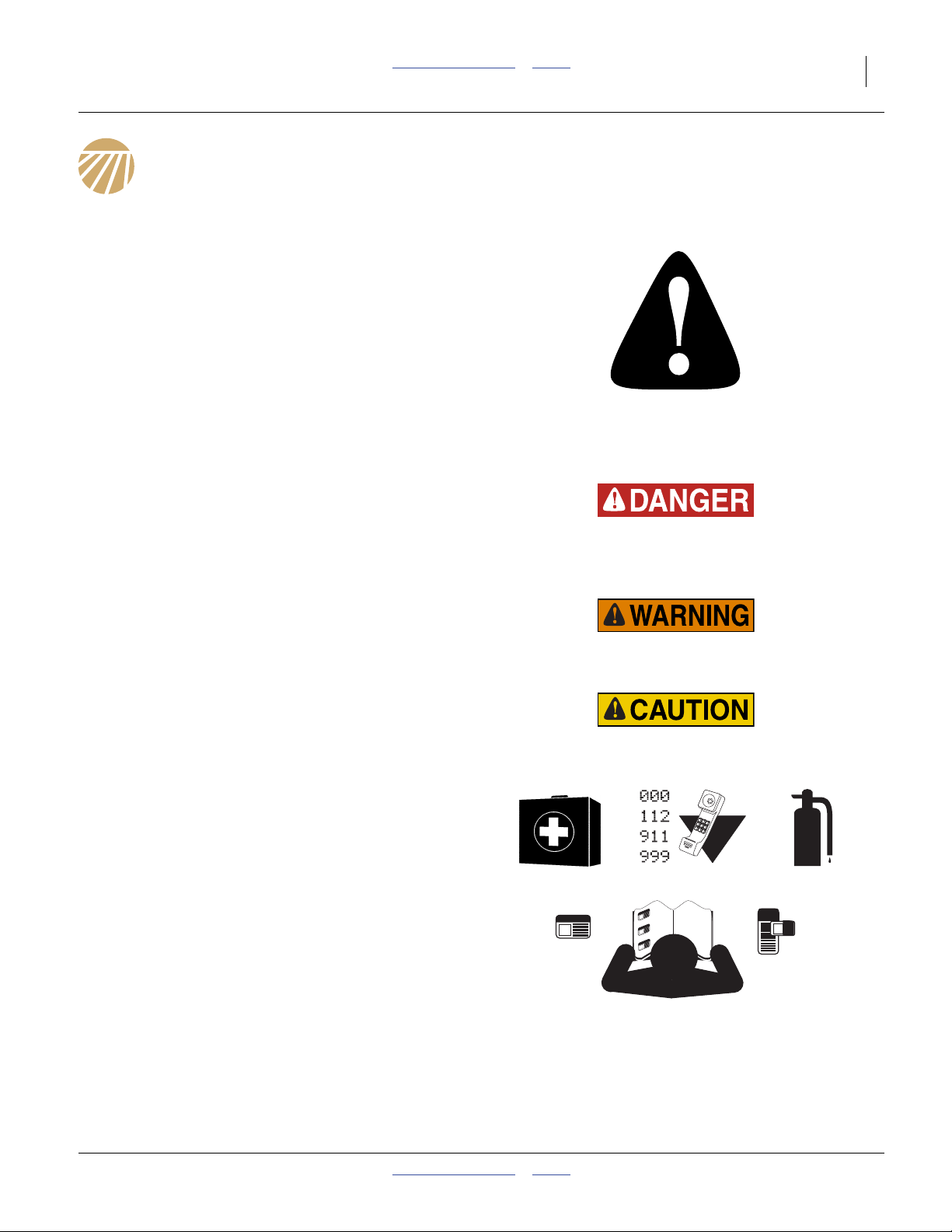
Look for Safety Symbol
The SAFETY ALERT SYMBOL indicates there is a
potential hazard to personal safety involved and extra
safety precaution must be taken. When you see this
symbol, be alert and carefully read the message that
follows it. In addition to design and configuration of
equipment, hazard control and accident prevention are
dependent upon the awareness, concern, prudence and
proper training of personnel involved in the operation,
transport, maintenance and storage of equipment.
Be Aware of Signal Words
Signal words designate a degree or level of hazard
seriousness.
DANGER indicates an imminently hazardous situation
which, if not avoided, will result in death or serious injury.
This signal word is limited to the most extreme situations,
typically for machine components that, for functional
purposes, cannot be guarded.
WARNING indicates a potentially hazardous situation
which, if not avoided, could result in death or serious
injury, and includes hazards that are exposed when
guards are removed. It may also be used to alert against
unsafe practices.
CAUTION indicates a potentially hazardous situation
which, if not avoided, may result in minor or moderate
injury. It may also be used to alert against unsafe
practices.
Prepare for Emergencies
▲ Be prepared if a fire starts
▲ Keep a first aid kit and fire extinguisher handy.
▲ Keep emergency numbers for doctor, ambulance, hospital
and fire department near phone.
Be Familiar with Safety Decals
▲ Read and understand “Safety Decals”onpage6,
thoroughly.
▲ Read all instructions noted on the decals.
▲ Keep decals clean. Replace damaged, faded and illegible
decals.
2012-10-17 Table of Contents Index 167-073M
Page 6
2 ADC2220 Table of Contents Index Great Plains Manufacturing, Inc.
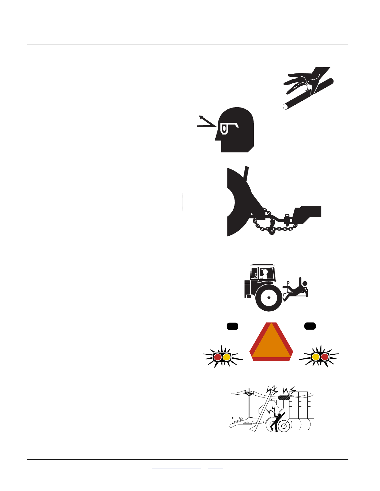
Avoid High Pressure Fluids
Escaping fluid under pressure can penetrate the skin,
causing serious injury.
▲ Avoid the hazard by relieving pressure before disconnecting
hydraulic lines.
▲ Use a piece of paper or cardboard, NOT BODY PARTS, to
check for suspected leaks.
▲ Wear protective gloves and safety glasses or goggles when
working with hydraulic systems.
▲ If an accident occurs, seek immediate medical attention
from a health care provider familiar with this type of injury.
Use A Safety Chain
▲ Use a safety chain to help control drawn machinery should
it separate from tractor drawbar.
▲ Use a chain with a strength rating equal to or greater than
the gross weight of towed machinery.
▲ Attach chain to tractor drawbar support or other specified
anchor location. Allow only enough slack in chain to permit
turning.
▲ Replace chain if any links or end fittings are broken,
stretched or damaged.
▲ Do not use safety chain for towing.
Keep Riders Off Machinery
Riders obstruct the operator’s view. Riders could be
struck by foreign objects or thrown from the machine.
▲ Never allow children to operate equipment.
▲ Keep all bystanders away from machine during operation.
Use Safety Lights and Devices
Slow-moving tractors and towed implements can create
a hazard when driven on public roads. They are difficult
to see, especially at night.
▲ Use flashing warning lights and turn signals whenever
driving on public roads.
▲ Use lights and devices provided with air cart and drill.
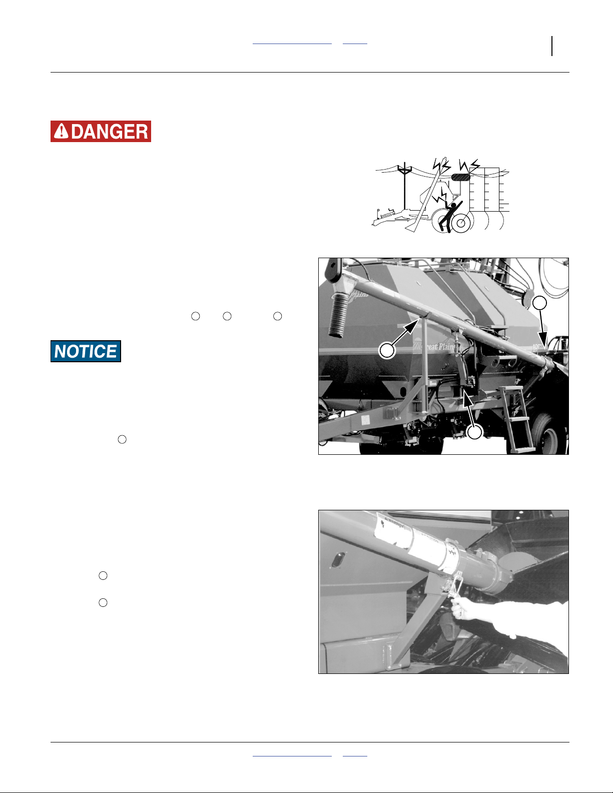
Check for Overhead Lines
Seed auger or drill markers contacting overhead
electrical lines can introduce lethal voltage levels on air
cart, drill and tractor frames. A person touching almost
any metal part can complete the circuit to ground,
resulting in serious injury or death. At higher voltages,
electrocution can occur without direct contact.
▲ Avoid overhead lines during seed loading, unloading and
marker operations.
167-073M Table of Contents Index 2012-10-17
Page 7

Great Plains Manufacturing, Inc. Table of Contents Index Important Safety Information 3
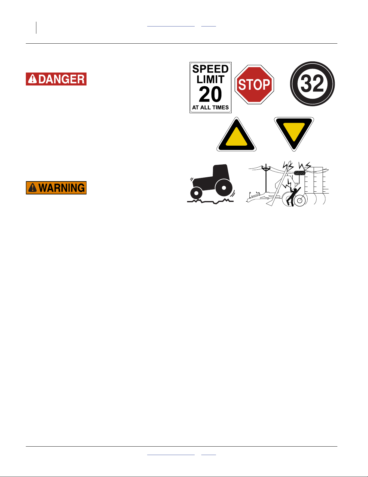
Transport Machinery Safely
Maximum transport speed for air cart is 20 mph
(32 km/h). Some rough terrains require a slower speed.
Sudden braking can cause a towed load to swerve and
upset.
▲ Do not tow a load which weighs more than 1.5 times the
weight of the tractor.
▲ Latch auger properly before transporting.
▲ Do not exceed 20 mph (32 km/h). Never travel at a speed
which does not allow adequate control of steering and
stopping. Reduce speed if towed load is not equipped with
brakes.
▲ Comply with national, regional and local laws.
▲ Follow your tractor manual recommendations for maximum
hitch loads. Insufficient weight on tractor steering wheels
will result in loss of control.
▲ Carry reflectors or flags to mark air cart and drill in case of
breakdown on the road.
▲ Keep clear of overhead power lines and other obstructions
when transporting. Refer to transport dimensions under
“Specifications and Capacities” on page 107.
Wear Protective Equipment
▲ Wear protective clothing and equipment.
▲ Wear clothing and equipment appropriate for the job. Avoid
loose-fitting clothing.
▲ Because prolonged exposure to loud noise can cause
hearing impairment or hearing loss, wear suitable hearing
protection such as earmuffs or earplugs.
▲ Because operating equipment safely requires your full
attention, avoid wearing entertainment headphones while
operating machinery.
2012-10-17 Table of Contents Index 167-073M
Page 8
4 ADC2220 Table of Contents Index Great Plains Manufacturing, Inc.
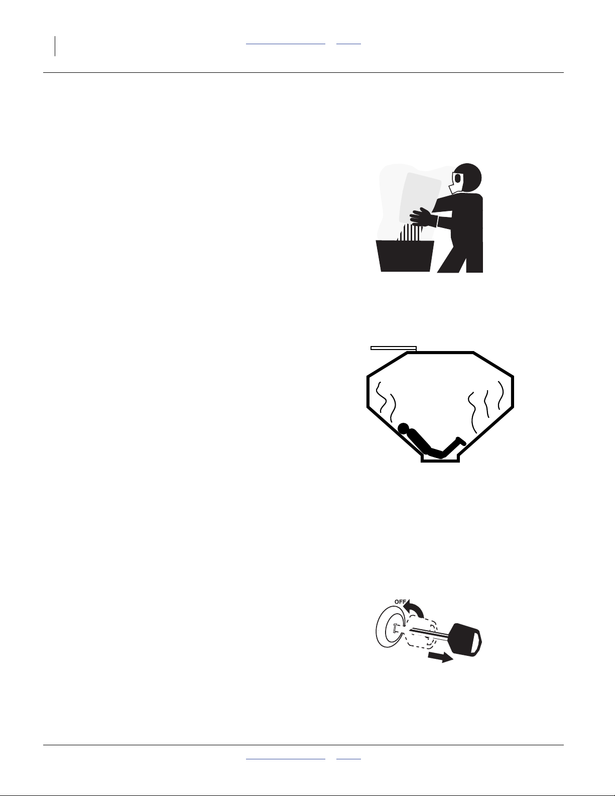
Handle Chemicals Properly
Agricultural chemicals can be dangerous. Improper use
can seriously injure persons, animals, plants, soil and
property.
▲ Do not use liquid treatments with air cart.
▲ Read and follow chemical manufacturer’s instructions.
▲ Wear protective clothing.
▲ Handle all chemicals with care.
▲ Avoid inhaling smoke from any type of chemical fire.
▲ Never drain, rinse or wash dispensers within 100 feet of a
freshwater source, nor at a car wash.
▲ Store or dispose of unused chemicals as specified by
chemical manufacturer.
▲ Dispose of empty chemical containers properly. Laws
generally require power rinsing or rinsing three times,
followed by perforation of the container to prevent re-use.
Confined Space
With grain or fertilizer present, and once used for
hazardous fertilizers, or seeds with hazardous
treatments, your hoppers may become
“permit-required confined spaces”
under applicable statutes, regulations, insurance rules or
business policy.
▲ A full, encrusted or bridged grain hopper can be a rapid
suffocation hazard.
▲ Even when empty, hazardous fumes or low oxygen may be
present. You can be quickly overcome even with the hopper
lid open.
▲ Do not enter a hopper for material loading, material
unloading, hopper cleaning or meter maintenance.
▲ Clean hopper by power washing from outside the hopper
top.
▲ Remove large obstructions, perform meter maintenance,
and perform sensor maintenance by removing meters from
bottom of empty hopper.
Shutdown and Storage
▲ Clean out and safely store or dispose of residual chemicals.
▲ Secure air cart using blocks and the stand provided.
▲ Store in an area where children normally do not play.
+
167-073M Table of Contents Index 2012-10-17
Page 9
Great Plains Manufacturing, Inc. Table of Contents Index Important Safety Information 5
Practice Safe Maintenance
▲ Understand procedure before doing work. Use proper tools
and equipment. Refer to this manual for additional
information.
▲ Work in a clean, dry area.
▲ Put tractor in park, turn off engine, and remove key before
performing maintenance.
▲ Make sure all moving parts have stopped and all system
pressure is relieved.
▲ Disconnect battery ground cable (-) before servicing or
adjusting electrical systems or before welding on cart.
▲ Inspect all parts. Make sure parts are in good condition and
installed properly.
▲ Remove buildup of grease, oil or debris.
▲ Remove all tools and unused parts from drill before
operation.
Tire Safety
Tire changing can be dangerous and should be
performed by trained personnel using correct tools and
equipment.
▲ When inflating tires, use a clip-on chuck and extension hose
long enough for you to stand to one side–not in front of or
over tire assembly. Use a safety cage if available.
▲ When removing and installing wheels, use wheel-handling
equipment adequate for weight involved.
Safety At All Times
Thoroughly read and understand the instructions in this
manual before operation. Read all instructions noted on
the safety decals.
▲ Be familiar with all air cart and drill functions.
▲ Operate machinery from the driver’s seat only.
▲ Do not leave air cart unattended with tractor engine
running.
▲ Do not dismount a moving tractor. Dismounting a moving
tractor could cause serious injury or death.
▲ Do not stand between the tractor and air cart during
hitching.
▲ Keep hands, feet and clothing away from power-driven
parts.
▲ Wear snug-fitting clothing to avoid entanglement with
moving parts.
2012-10-17 Table of Contents Index 167-073M
Page 10
6 ADC2220 Table of Contents Index Great Plains Manufacturing, Inc.
Safety Decals
Safety Reflectors and Decals
Your air cart comes equipped with all lights, safety
reflectors and decals in place. They were designed to
help you safely operate your air cart.
▲ Read and follow decal directions.
▲ Keep lights in operating condition.
▲ Keep all safety decals clean and legible.
▲ Replace all damaged or missing decals. Order new decals
from your Great Plains dealer. Refer to this section for
proper decal placement.
▲ When ordering new parts or components, also request
corresponding safety decals.
818-055C
Slow Moving Vehicle Reflector
On the back of the aft hopper, frame center;
1 total
To install new decals:
1. Clean the area on which the decal is to be placed.
2. Peel backing from decal. Press firmly on surface,
being careful not to cause air bubbles under decal.
16192
838-266C
Red Reflectors
On the outside corners of aft hopper;
2 total
838-265C
Amber Reflectors
Front and outside leading corner of front hopper,
outside rear corner of rear hopper;
6 total
16251
16251
167-073M Table of Contents Index 2012-10-17
Page 11
Great Plains Manufacturing, Inc. Table of Contents Index Important Safety Information 7
818-557C
Danger: Cannot Read English
On top of left draw bar near hitch,
1 total
16193
818-624C
Danger: Hitch Crushing Hazard
On the left vertical beam at rear hitch
CTA 4000 setup option only);
1 total
818-627C
Danger: Electrocution Hazard
On the right side, outside face of front frame;
2 total
16251
16193
16190
2012-10-17 Table of Contents Index 167-073M
Page 12
8 ADC2220 Table of Contents Index Great Plains Manufacturing, Inc.
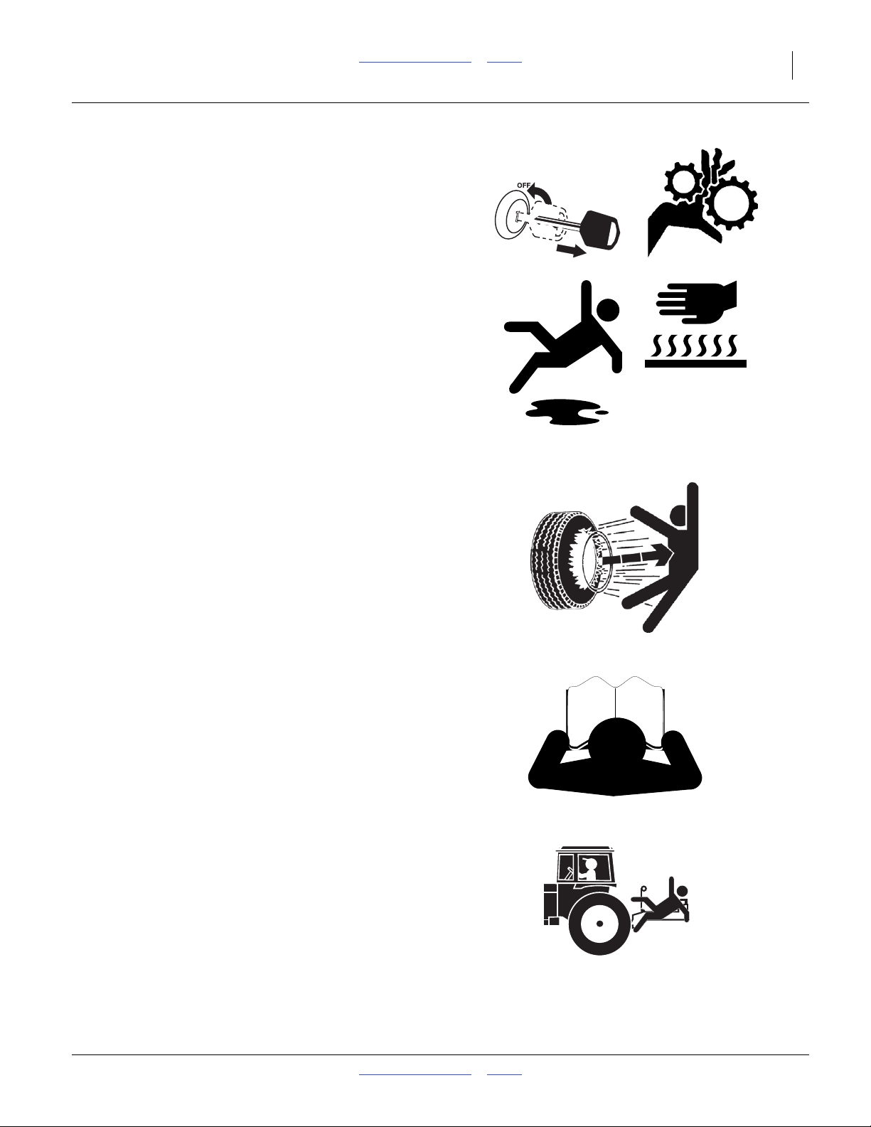
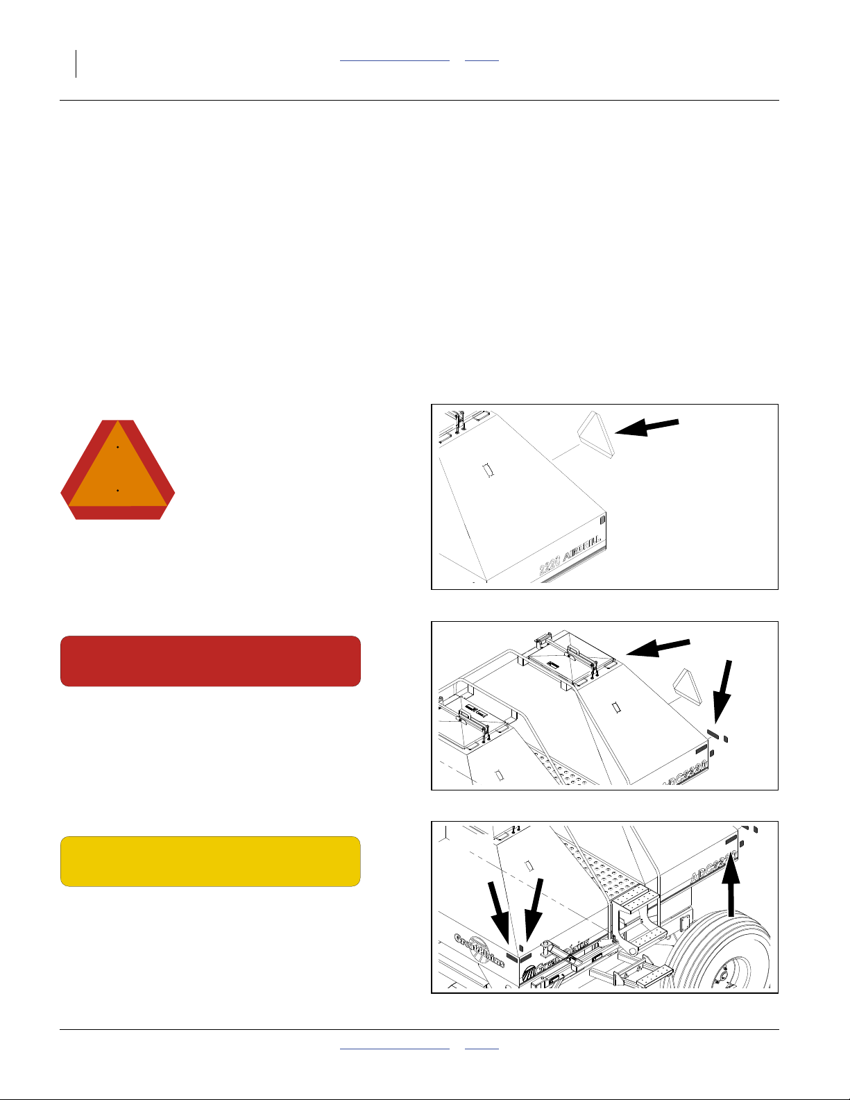
818-633C
Danger: Missing Guard Hazard
On the auger tube near inlet,
1 total
16190
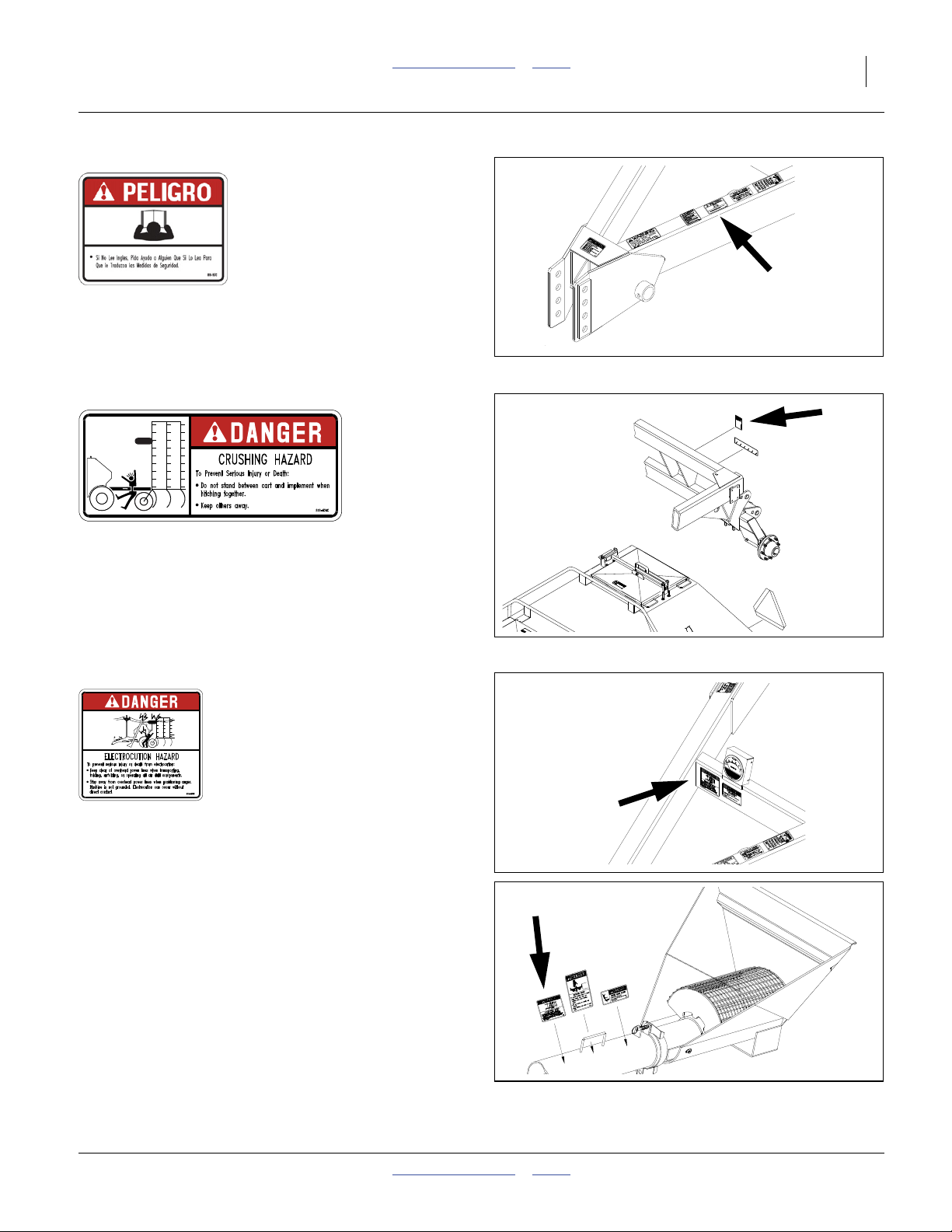
818-634C
Danger: Rotating Auger
On the auger tube near inlet,
1 total
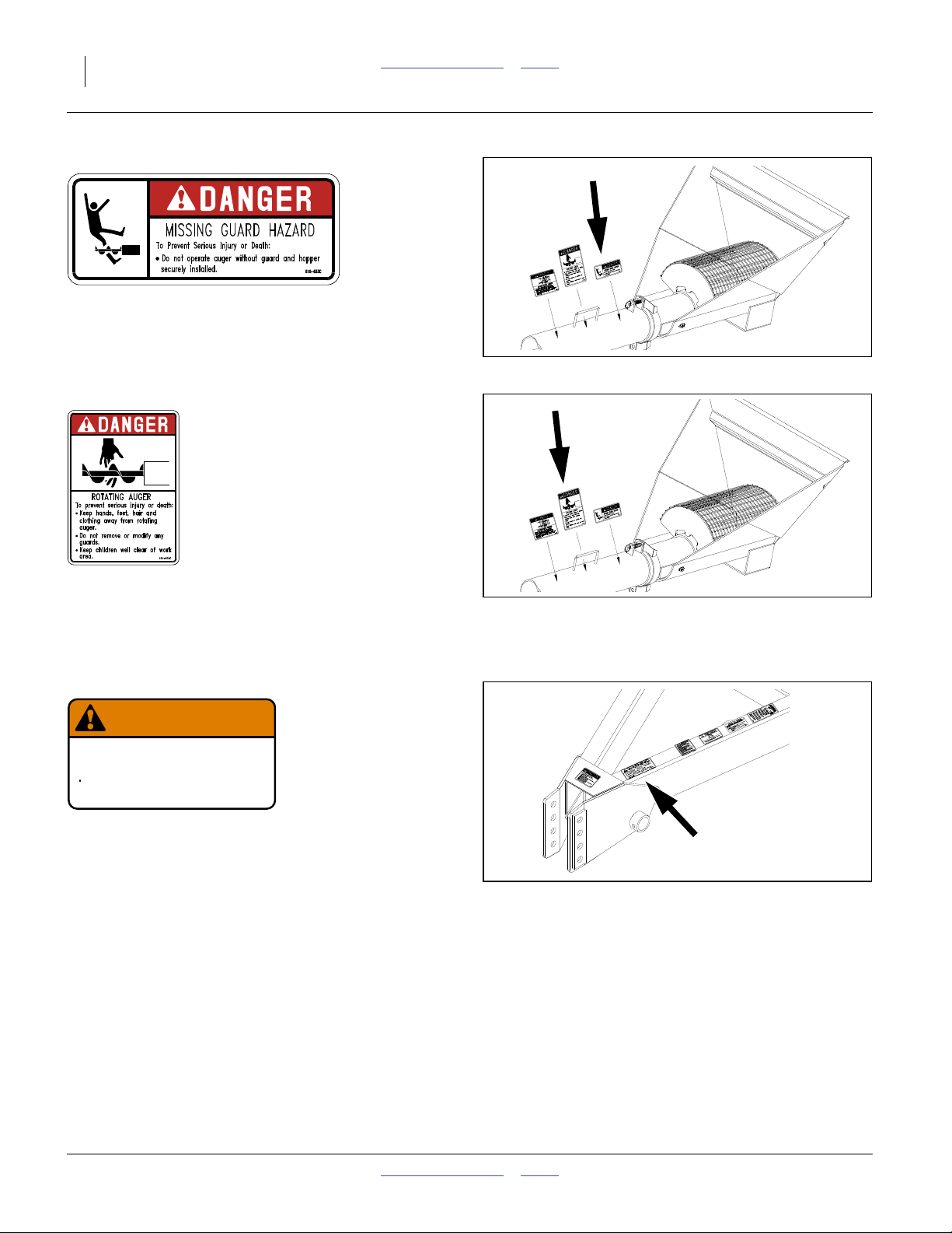
818-188C
WARNING
EXCESSIVE SPEED HAZARD
To Prevent Serious Injury or Death:
Do Not exceed 20 mph maximum transport
speed. Loss of vehicle control and/or machine
can result.
Warning: Excessive Speed
On top of tongue at hitch;
1 total
818-188C Rev. C
16190
16193
167-073M Table of Contents Index 2012-10-17
Page 13
Great Plains Manufacturing, Inc. Table of Contents Index Important Safety Information 9
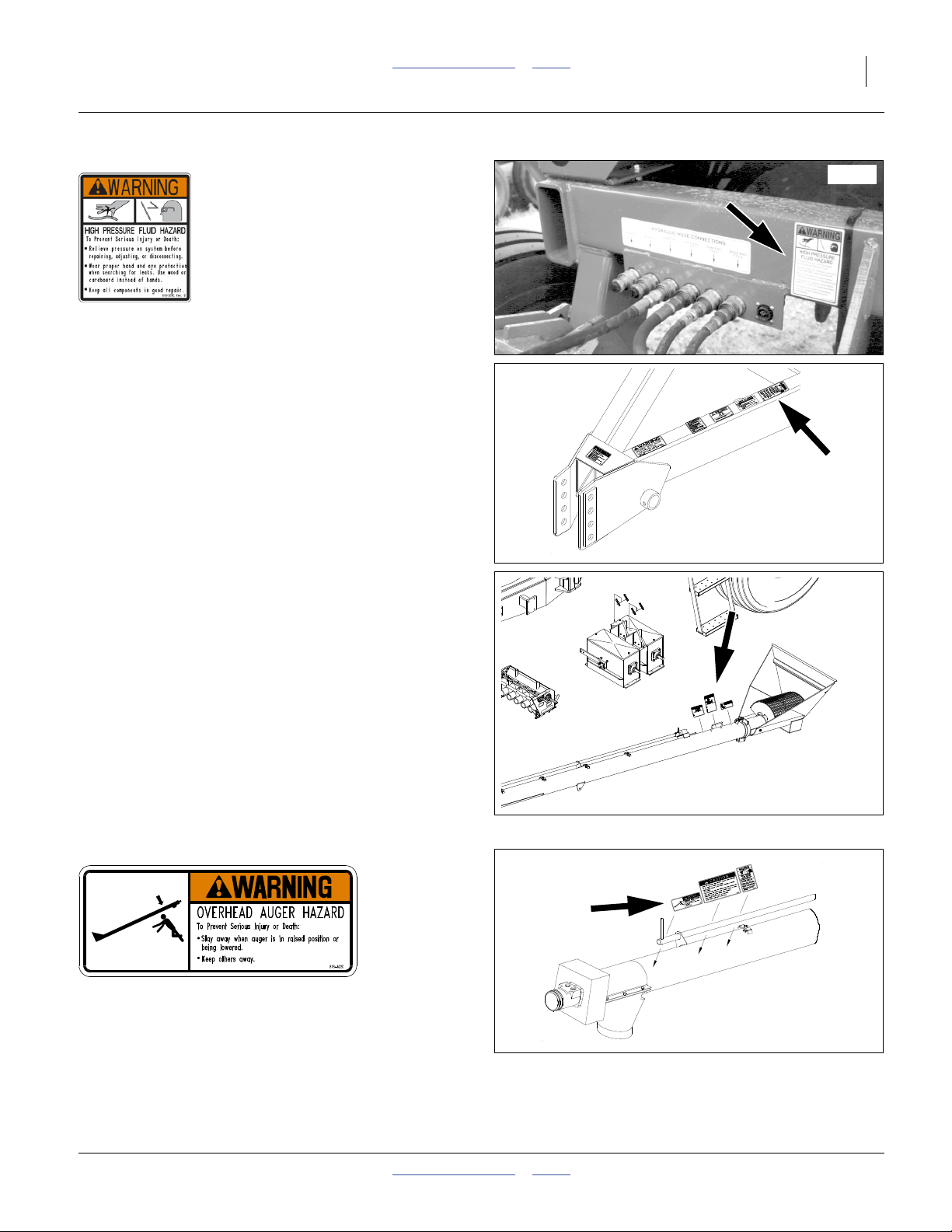
818-339C
Warning: High Pressure Fluid Hazard
At hydraulic connection panel,
on hitch right drawbar,
on seed auger near hand-hold;
3 total
16191
16193
16251
818-622C
Warning: Overhead Auger Hazard
On auger near each end,
2 total on auger tube
2012-10-17 Table of Contents Index 167-073M
16189
Page 14
10 ADC2220 Table of Contents Index Great Plains Manufacturing, Inc.
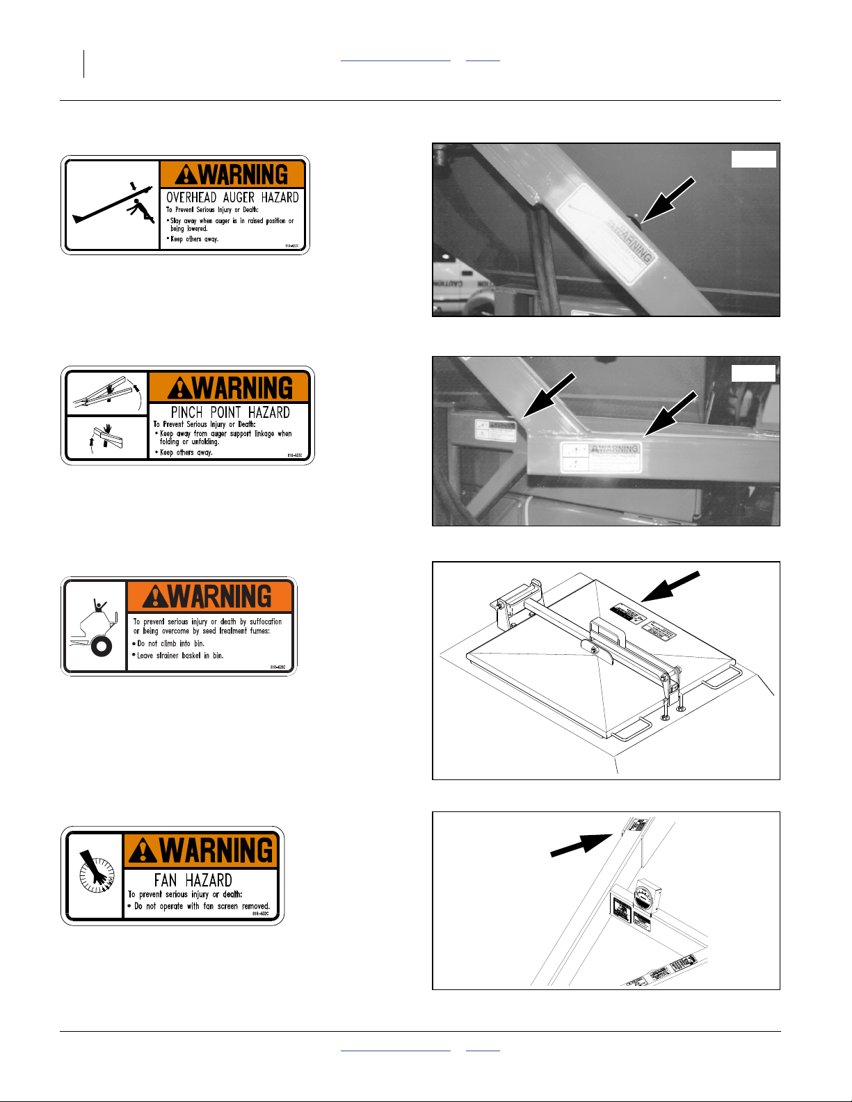
818-622C
16183
Warning: Overhead Auger Hazard
On auger swing arm,
1 total on arm
818-623C
16182
Warning: Pinch Point Hazard
On both sides of auger swing arm;
2 total
818-628C
Warning: Confined Space
On lid, walkboard side, each hopper;
2 total
818-632C
16191
Warning: Fan Hazard
On the left tongue tube at fan,
1 total
167-073M Table of Contents Index 2012-10-17
16193
Page 15
Great Plains Manufacturing, Inc. Table of Contents Index Important Safety Information 11
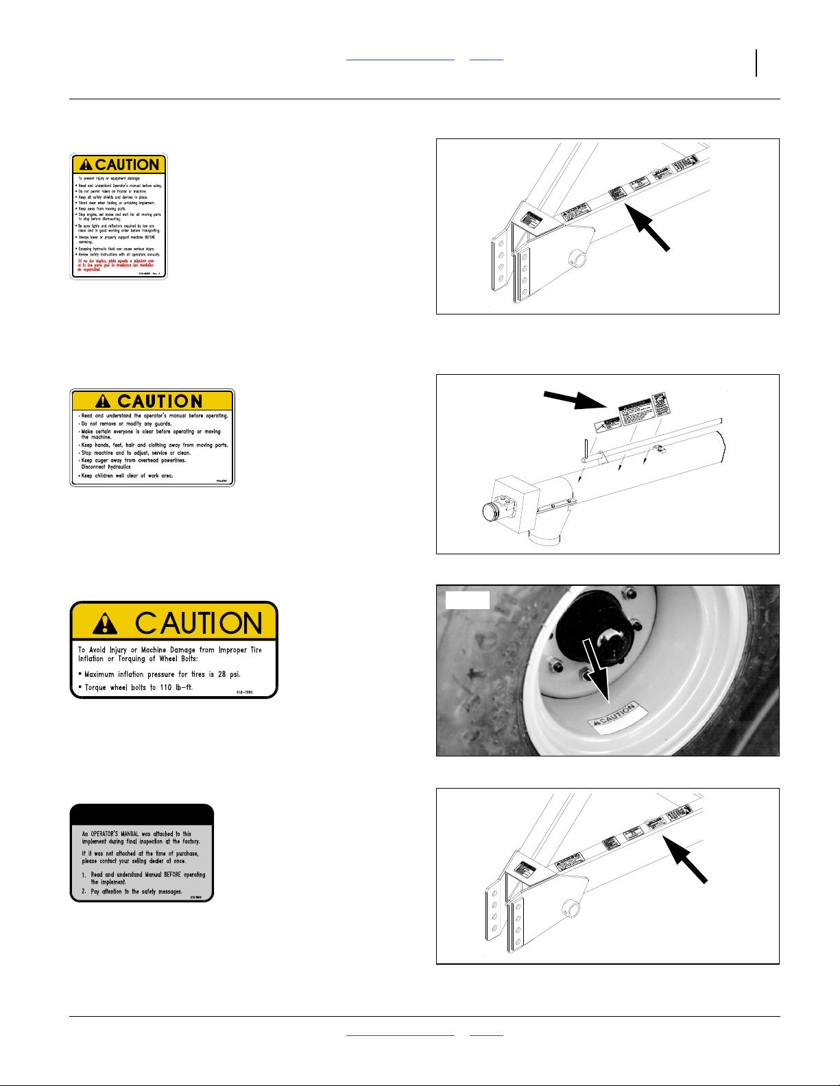
818-630C
Caution: General
On the main tool bar at hitch;
1 total
818-635C
Caution: Auger General
On discharge end of auger:
1 total
818-789C
16193
16189
16247
Caution: Tire Pressure
On each wheel rim:
2 total
818-560C
NOTICE TO OWNER
Safety: Notice to Owner
On tongue near hitch;
1 total
2012-10-17 Table of Contents Index 167-073M
16193
Page 16
12 ADC2220 Table of Contents Index Great Plains Manufacturing, Inc.
Introduction
Great Plains welcomes you to its growing family of new
product owners. Your Air Drill Cart has been designed
with care and built by skilled workers using quality
materials. Proper setup, maintenance, and safe
operating practices will help you get years of satisfactory
use from the machine.
Air Cart Document Family
167-073M Owner’s Manual (this document)
including Seed Rate charts
167-073P Parts Manual
Description of Unit
The ADC2220 is a pull-type implement for volumetric
seeding. A hydraulic fan creates an airflow to supply
seed and dry treatments to a compatible trailing Great
Plains drill.
The ADC2220 Air Drill Cart is compatible with the
following Great Plains air drills:
ADI334 34-foot Air Drill Implement
ADI345 45-foot Air Drill Implement
CTA4000 40-foot Conventional Tillage Air Drill
CTA4000HD Heavy Duty Tillage Air Drill
NTA3010 30-foot No-Till Air Drill
NTA3510 35-foot No-Till Air Drill
Note: If the air cart and drill were not purchased on the
same original factory order, one or both may not
include compatible components. The implements
above may be configured for use with other air
carts. Check with your dealer before hitching.
Intended Usage
Use the air cart and drill to seed production-agriculture
crops only. Do not modify the air cart for use with
attachments other than Great Plains options and
accessories specified for use with the air cart.
Using This Manual
This manual will familiarize you with safety, assembly,
operation, adjustments, troubleshooting, and
maintenance. Read this manual and follow the
recommendations to help ensure safe and efficient
operation.
The information in this manual is current at printing.
Some parts may change to assure top performance.
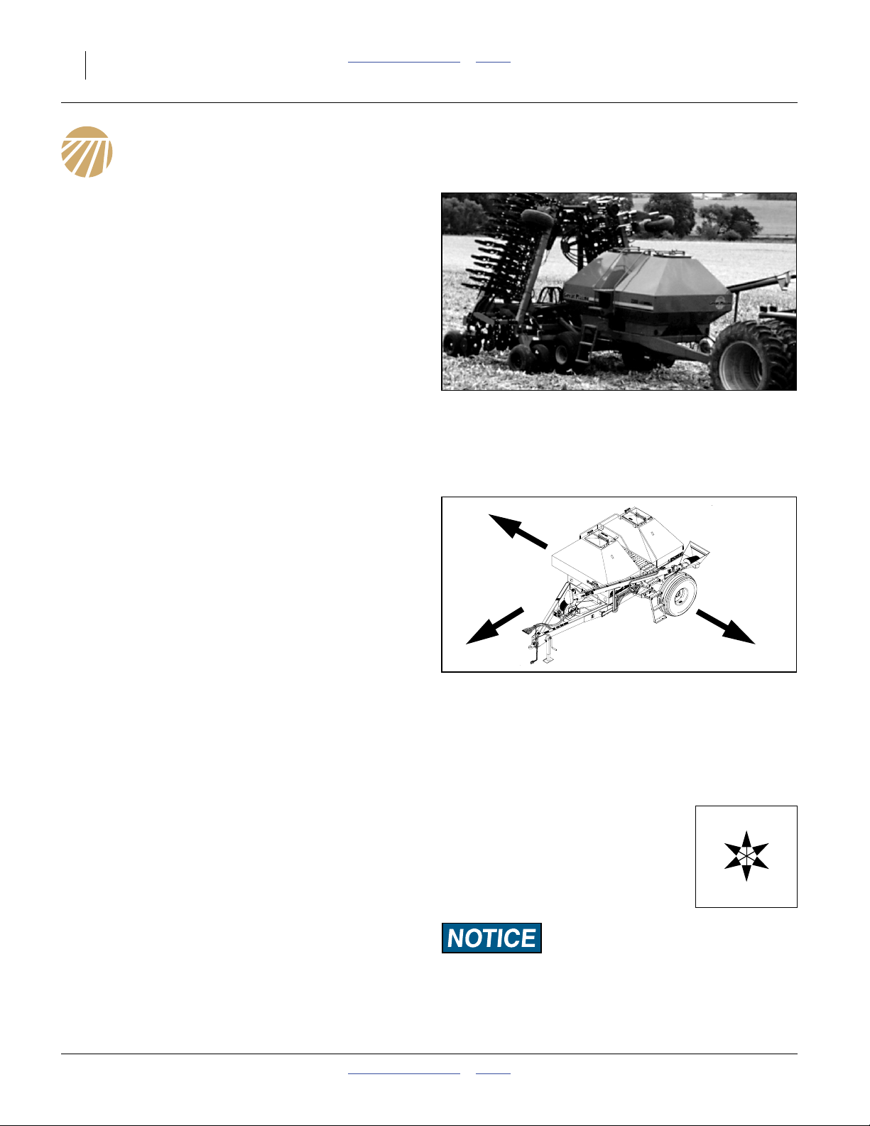
Figure 1
Air Cart and Drill
16179
R
L
R
F
16263
U
B
L
D
Figure 2
Left/Right Notation
Definitions
The following terms are used throughout this manual.
Right-hand and left-hand as used in
this manual are determined by facing
the direction the machine will travel
while in use unless otherwise stated.
An orientation rose in some line art
illustrations shows the directions of:
Up, Back, Left, Down, Front, Right.
A crucial point of information related to the preceding topic.
For safe and correct operation, read and follow the directions
provided before continuing.
Note: Useful information related to the preceding topic.
167-073M Table of Contents Index 2012-10-17
Page 17
Great Plains Manufacturing, Inc. Table of Contents Index Introduction 13
Owner Assistance
If you need customer service or repair parts, contact a
Great Plains dealer. They have trained personnel, repair
parts and equipment specially designed for Great Plains
products.
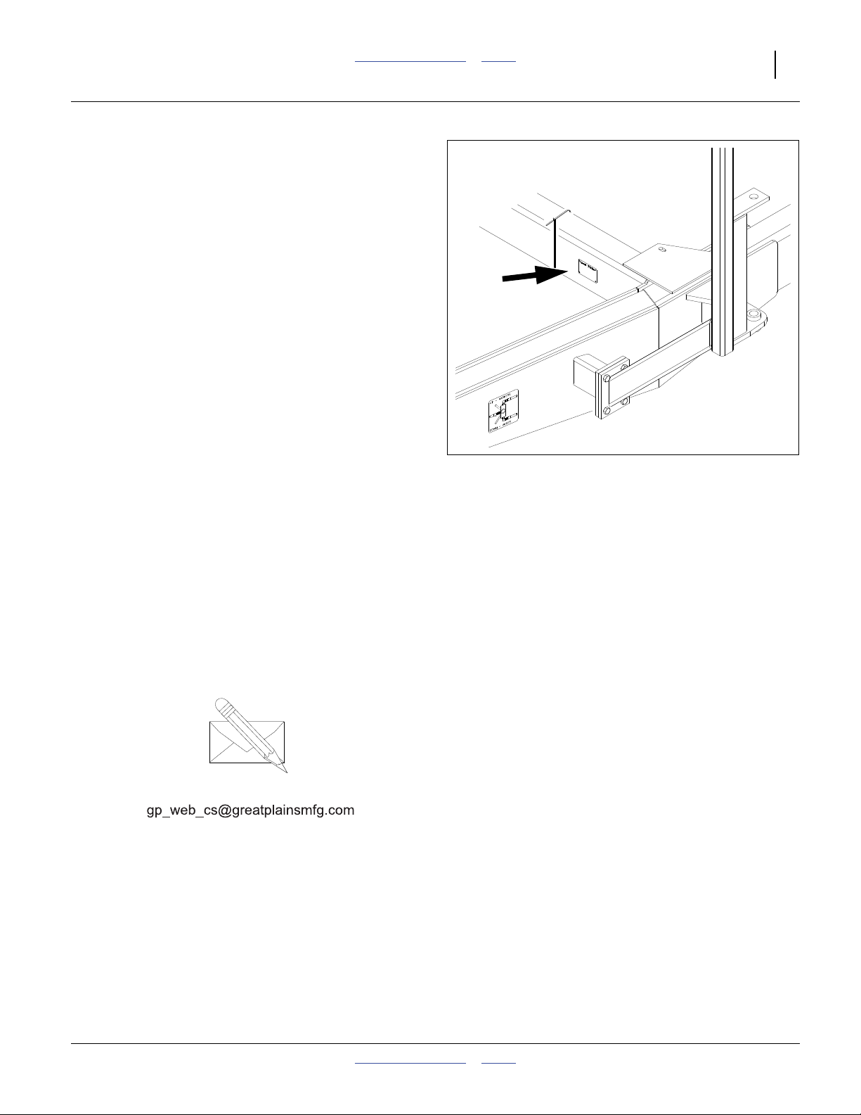
Refer to Figure 3
Your machine’s parts were specially designed and
should only be replaced with Great Plains parts. Always
use the serial and model number when ordering parts
from your Great Plains dealer. The serial-number plate is
located on the left side of the cart frame below the front
hopper.
Record your air cart model and serial number here for
quick reference:
Model Number:__________________________
Serial Number: __________________________
Your Great Plains dealer wants you to be satisfied with
your new machine. If you do not understand any part of
this manual or are not satisfied with the service received,
please take the following actions.
1. Discuss the matter with your dealership service
manager. Make sure they are aware of any problems
so they can assist you.
2. If you are still unsatisfied, seek out the owner or
general manager of the dealership.
For further assistance write to:
Figure 3
Serial Number Plate
16194
Product Support
Great Plains Mfg. Inc., Service Department
PO Box 5060
Salina, KS 67402-5060
785-823-3276
2012-10-17 Table of Contents Index 167-073M
Page 18

14 ADC2220 Table of Contents Index Great Plains Manufacturing, Inc.
Preparation and Setup
This section helps you prepare your tractor, air cart and
drill for use. Before using the air cart in the field, you
must hitch the air cart to a suitable tractor, compatible
drill, and also setup the drill.
Initial Setup
Prior to first use, the following items need to be checked
or completed:
• The cart must have the correct sprockets for your drill.
See “Cart Drive System” on page 114.
• The seed monitor console must be installed in the
tractor cab. See “Install Loup II Console” on
page 115.
• Initial configuration data must be loaded in the
console. See “Initial Loup-II Setup” on page 116.
Pre-Setup Checklist
1. Read and understand “Important Safety
Information” on page 1.
2. Check that all working parts are moving freely, bolts
are tight, and cotter pins are spread.
3. Check that all grease fittings are in place and
lubricated. See “Lubrication and Scheduled
Maintenance” on page 99.
4. Check that all safety decals and reflectors are
correctly located and legible. Replace if damaged.
See “Safety Decals” on page 6.
5. Inflate tires to pressure recommended and tighten
wheel bolts as specified. “Appendix A - Reference
Information” on page 107.
Hitching
When ready for planting, the air cart is part of an
assembly that includes the tractor, the air cart, and the
drill. When hitching for the first time, hitch cart to tractor
first.
Note: Static tongue weight of a loaded cart is about 5,500
pounds on level ground and more when facing
downhill.
Once the air cart and drill are hitched together, they are
usually left connected, unless parking or storage
considerations require separation.
This manual includes full details only for the leading air
cart’s forward hitch. Consult the drill manual for trailing
drill hitching.
Crushing Hazard:
You may be severely injured or killed by being crushed
between the tractor, air cart and drill. Do not stand or place
any part of your body between machines being hitched. Stop
tractor engine and set park brake before installing hitch pins.
167-073M Table of Contents Index 2012-10-17
Page 19
Great Plains Manufacturing, Inc. Table of Contents Index Preparation and Setup 15
Hitching Air Cart to Tractor
To ensure consistent planting at the drill, the main frame
of the air cart needs to be level. Set the tongue height
before hitching for the first time.
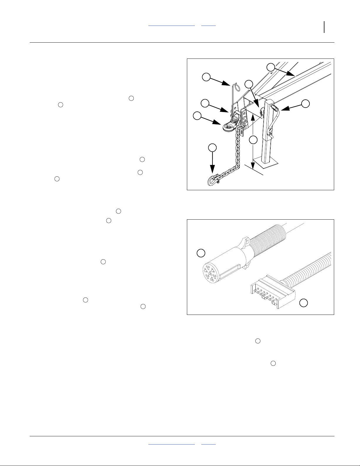
Refer to Figure 4
1. Using the crank on the jack stand , adjust the
height of the tongue to:
as measured from the ground to the top of the
tongue above the hitch holes center-line. The cart
frame is level at this height.
2. Back the tractor up to the cart, and confirm that
when hitched, the cart tongue will remain at this
height. If not, adjust either the height of the tractor
hitch, or the location of the hitch strap .
2
30 inches (76.2cm).
1
5
3
7
4
5
6
8
1
2
To adjust the height of the hitch strap , remove the
4
bolts , and reset the strap up or down.
If the strap needs to be moved so far that only one
bolt would be holding it, the strap may be inverted.
Strap inversion requires removing the bolt that
retains the spring hose loop , and re-mounting it.
3. Use the jack stand crank to raise the hitch strap
slightly. Back the tractor so that its drawbar is aligned
with the strap hole.
4. Shut off the tractor and set the parking brake.
5. Insert and secure the hitch pin.
6. Attach the safety chain to a suitable anchor on the
tractor.
7. Operate the jack stand crank to retract the inner leg
and base several inches. Secure the crank handle in
the spring clip on the stand.
8. Remove the pin at the stand swivel. Remove the
stand and re-pin it on the storage stob (not visible
in figure) inside the hitch beam.
7
3
1
6
5
8
Make Electrical Connections
The cart has connections in front and back.
Refer to Figure 5
Make sure tractor is shut down with accessory power off
before making connections.
Figure 4
Hitch
26300
1
2
Figure 5
Cart Front Hitch Connections
1. Mate the lighting plug to the outlet connector on
the tractor. This connection is also passed through to
the back of the cart for the trailing drill.
2. Mate the seed monitor plug to the outlet
connector on the tractor. This connection is also
passed through to the back of the cart.
3. Secure cables so they are clear of moving parts at
the hitch.
1
2
26467
29099
2012-10-17 Table of Contents Index 167-073M
Page 20
16 ADC2220 Table of Contents Index Great Plains Manufacturing, Inc.
Make Hydraulic Connections
High Pressure Fluid Hazard:
Only trained personnel should work on system hydraulics!
Escaping fluid under pressure can penetrate the skin causing
serious injury. Check all hydraulic lines and fittings before
applying pressure. Use paper or cardboard, NOT BODY
PARTS, to check for suspected leaks. Wear protective gloves
and safety glasses or goggles when working with hydraulic
systems. If an accident occurs, seek immediate medical
attention from a physician familiar with this type of injury.
The air cart itself consumes hydraulic power for one or
two circuits, and has a low pressure sump return line.
The cart also passes through three circuits necessary for
drill operations.
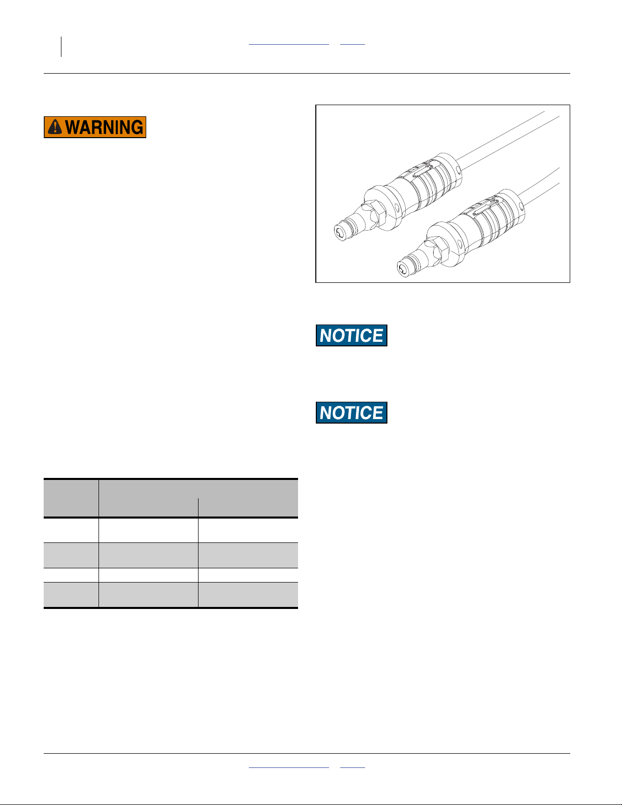
Current Style Color Coded Hose Handles
Refer to Figure 6
Great Plains hydraulic hoses have color coded handle
grips to help you hookup hoses to your tractor outlets.
Hoses that go to the same remote valve are marked with
the same color.
To distinguish hoses on the same hydraulic circuit, refer
to the symbol molded into the handle grip. Hoses with an
extended-cylinder symbol feed cylinder base ends.
Hoses with a retracted-cylinder symbol feed cylinder rod
ends.
Hose connections are also passed through to a rear
panel when the air cart leads the drill. Hoses that go to
the same remote valve are marked with the same color.
Color
Code
<none>
(decal)
Black Hydraulic Fan
(Extend side only)
Blue <no function> Lift Cylinders
Green
Hydraulic Function
on Cart on Drill
SUMP return (available)
Fold Cylinders
(ADI & NTA only)
Auger
Fold (ADI only)
Marker Cylinders
Figure 6
Color Coded Hose Grips
For CTA implements, some tractors require an auxiliary flow
kit to prevent damage to the hydraulic pump. Contact a factory
trained service technician before hooking to cart and CTA
implement.
The hose and large connector labeled sump refers to high
volume hydraulic motor return and should always be
connected to the port on the tractor capable of handling high
volume low pressure return oil. DO NOT connect this line to
low volume case drain lines or low volume sump lines on the
tractor. See tractor manufacturer’s recommendations for high
volume hydraulic motor return.
31733
1. Make sure all tractor levers are in neutral or float, or
tractor hydraulics are off, before making connections.
Carts Y1007 and Earlier
Air carts serial number Y1077 and earlier have different
hydraulic connections. See “Hook-Up: Y1077 and
Earlier Carts” on page 117.
Carts Y1078 and Later
See “Y1078+ Hydraulic Connections” on page 17.
167-073M Table of Contents Index 2012-10-17
Page 21
Great Plains Manufacturing, Inc. Table of Contents Index Preparation and Setup 17
Older Style Hoses with Color Ties
Refer to Figure 7
To distinguish hoses on the same hydraulic circuit, refer
to plastic hose label. The hose under an
extended-cylinder symbol feeds a cylinder base end. The
hose under a retracted-cylinder symbol feeds a cylinder
rod end.
Hose connections are also passed through to a rear
panel when the air cart leads the drill. Hoses that go to
the same remote valve are marked with the same color
tie.
Color
Code
<none>
(decal)
Yellow Hydraulic Fan
(Extend side only)
Blue <no function> Lift Cylinders
0range
Make sure all tractor levers are in neutral or float, or
tractor hydraulics are off, before making connections.
Y1078+ Hydraulic Connections
Black (hose grips) or Yellow (ties): Fan/Fold
If your tractor has a priority circuit for hydraulic motors,
connect the fan (yellow) to this circuit.
Note: Fan hoses are not the same size. A1⁄2inch and a
3
⁄8inch hose are paired together.
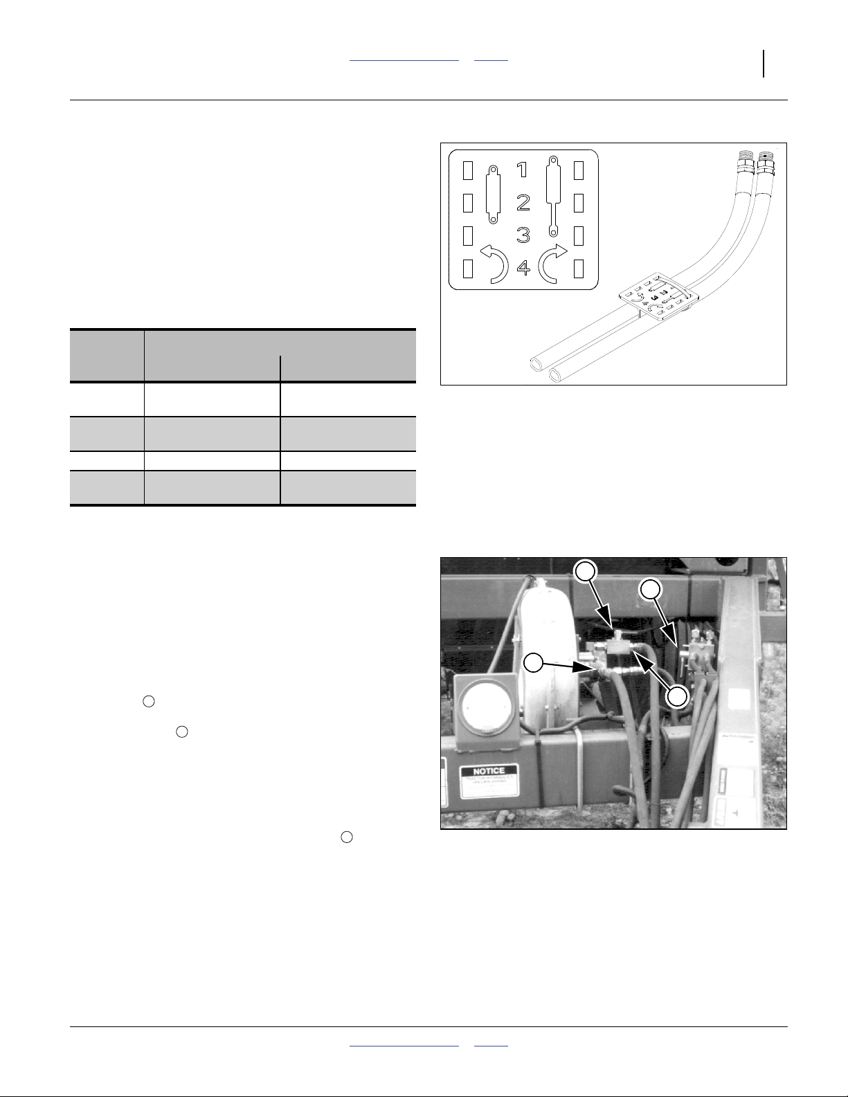
Refer to Figure 8
2. Connect the hose with the Extended-Cylinder
symbol to the side of the circuit you choose to be
the pressure side. This hose supplies the fan (at fan
shutoff valve ) and rear port F.
3. Hook fan hose under Retracted-Cylinder symbol to
the other tractor outlet. This hose is not used by the
fan, and passes directly to rear port E.
4. Connect hose with SUMP decal to the tractor
hydraulic reservoir. Refer to your tractor operator’s
manual for instructions. The sump hose is also
routed to rear port G.
Note: Rear ports E and F are Fold on ADI and NTA
1
implements.
Hydraulic Function
on Cart on Drill
SUMP return (available)
Fold Cylinders
(ADI & NTA only)
Auger
2
Fold (ADI only)
Marker Cylinders
3
Figure 7
Plastic Hose Label
2
3
Figure 8
Y1078+ Fan Hook-Up
817-348c
17641
4
1
17172
2012-10-17 Table of Contents Index 167-073M
Page 22

18 ADC2220 Table of Contents Index Great Plains Manufacturing, Inc.
Sump First and Last
Machine Damage Risk:
Seals in the hydraulic fan motor can be damaged if the return
line is pressurized. Always connect the SUMP hose first and
disconnect it last. The sump hose has a larger (1.06in)
quick-connect coupling.
Refer to Figure 9
Note: For proper hydraulic flow, use a poppet-style,
Pioneer quick coupler to connect sump hose to
tractor.
Green (hose grips) or Orange (ties): Auger/Marker (& Fold on ADI)
Connect orange-coded hoses to tractor outlets capable
Figure 9
Poppet-Style Coupler for Sump
17646
of continuous flow (although less than required for the
fan). This circuit is used by the cart for the auger, and
may also be directed to rear ports A and B for use by
Markers (not all implements have Markers).
A diverter valve on the cart ( in Figure 8) switches flow
4
between auger and rear ports.
Blue: Implement Lift
Connect blue-coded lift hoses to tractor outlets. This
3
⁄8inch hose circuit is unused by the air cart, passing
through to rear ports C and D. It is used for Lift by all
implements.
Set Up the Implement
This manual only covers air cart setup. Consult the
Operator’s Manual for the implement for additional setup
steps required prior to operation.
167-073M Table of Contents Index 2012-10-17
Page 23

Great Plains Manufacturing, Inc. Table of Contents Index 19
Operating Instructions
This section covers general operating procedures. It
assumes that setup items have been completed for both
air cart and implement.
Experience, machine familiarity and the following
information will lead to efficient operation and good
working habits. Always operate farm machinery with
safety in mind.
General Description
Seed metering is powered by a cart tire and driven at a
rate proportional to distance traveled. Each seed bin is
self-contained and has its own metering device. The
seed bins are sealed and held at the same pressure as
the meter boxes so metering is controlled
mechanically–not by air-flow fluctuations. The metered
seed is carried by air through the hoses to the
distribution towers on the implement. These towers then
divide the air and seed into individual rows.
The metering devices are driven through an
electromagnetic clutch. The clutch only engages if the
implement is lowered, operating an adjustable lift switch.
Seed metering is shut off automatically when the drill is
lifted for headland turns.
Pre-Start Checklist
❑ Lubricate the cart as indicated under Lubrication,
“Maintenance and Lubrication” on page 95.
❑ Check the tires for proper inflation according to “Tire
Inflation Chart” on page 107.
❑ Check the chains for proper tension and alignment
as shown under Drive System Adjustments,
“Adjustments” on page 65.
❑ Check for worn or damaged parts and repair or
replace before going to the field.
❑ Check all nuts, bolts and screws. Tighten bolts as
specified on “Torque Values Chart” on page 113
❑ Check height switch on implement.
2012-10-17 Table of Contents Index 167-073M
Page 24
20 ADC2220 Table of Contents Index Great Plains Manufacturing, Inc.
Hopper Lids
Keep lids closed. Keep tightly closed for operations.
Keep loosely closed for storage. Open only for material
loading, hopper clean-out and lid maintenance.
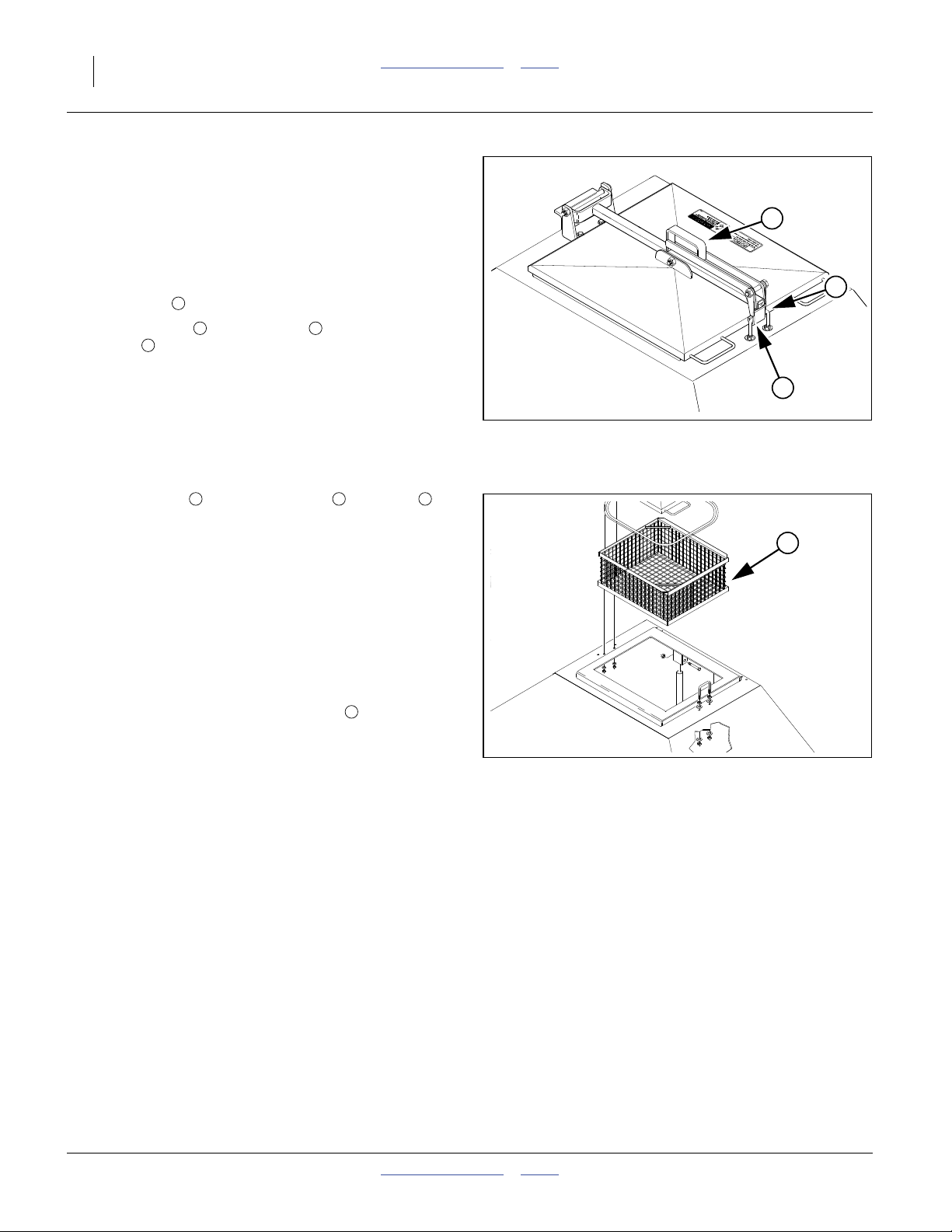
Lid Opening
Refer to Figure 10
1. Lift handle .
2. Swing handle out until hook releases from
U-bolt .
3. Move hook clear of U-bolt and re-close handle.
4. Swing lid open.
2
2 3
4
2
4
3
Lid Closing
1. Open handle and engage hook on U-bolt .
2. Close handle with hook engaged for operations or
short-term parking.
For long-term storage, do not engage hook or latch
handle, to avoid deforming the seal.
3. For storage, particularly unlatched, a locked chain
deters entry.
2 3 4
Strainer
Refer to Figure 11
Each hopper is equipped with a strainer intended to:
• capture foreign matter in seed and materials that is too
large to pass through the meter, and
• prevent entry.
Leave the strainer in place except during strainer and
hopper cleaning.
Check the strainer for residue prior to each loading
operation. Remove, empty and return it to the hopper.
For strainer or hopper cleaning, the strainer lifts out when
the lid is fully open.
5
Figure 10
Hopper Lid Latched
Figure 11
Hopper Strainer
16191
5
16137
167-073M Table of Contents Index 2012-10-17
Page 25
Great Plains Manufacturing, Inc. Table of Contents Index Operating Instructions 21
Auger Operations
Electrocution Hazard:
Keep clear of overhead power lines when positioning auger.
The auger can reach 15 feet (4.6 m) above ground level during
positioning operations. If it contacts a power line, nearly all
metal parts of the cart, tractor and drill will have lethal
voltage present, and anyone touching them can complete the
circuit to ground, resulting in serious injury or death. With
very high voltages, electrocution can occur without direct
contact.
This section covers only basic auger operations. For
specific tasks, see:
“Unloading the Cart” on page 34, and
“Loading Material” on page 29.
Refer to Figure 12
Latch the auger into its cradles ( and ) and pin the
inner arm pivot, whenever the auger is not in use.
1 2 3
2
Machine Damage Risk: To avoid auger damage during cart
movement, do not rely solely on the arm pin to secure the
auger in the stored configuration. Use both pin and latch.
Deploying Auger
For material loading, the inner arm is left pinned to the
frame. The pin is located at the mid pivot of the auger
arm assembly.
The back (inlet) end of the auger has a grasp handle.
Refer to Figure 13 and Figure 12
1. If hopper is facing to the side or down, turn it upright
(page 23).
2. Release the rear latch clamp and strap.
3. Hold a grasp handle near the auger inlet hopper.
4. Pull the rear end of the auger out of the rear
cradle .
5. Tilt the forward end of the auger up out of the forward
cradle .
6. Pull the auger away from the cart and set the inlet
end on the ground.
3
2
1
1
3
Figure 12
Auger Latched for Movement
29012
Auger Hydraulic Controls
Operating the auger involves one or two valves on the
cart, in addition to the tractor lever for the hydraulic
circuit.
7. Set the tractor circuit for Auger/Marker to Neutral or
Float before setting the cart diverter valve.
2012-10-17 Table of Contents Index 167-073M
Figure 13
Auger Latch Clamp
16120
Page 26
22 ADC2220 Table of Contents Index Great Plains Manufacturing, Inc.
Verify Auger Off
A valve at the inlet end of the auger controls On/Off and
direction of auger rotation. It has an operating handle at
each end of the auger tube.
Refer to Figure 14
Make sure the control at the auger itself is set to Off
before operating any other hydraulic controls.
If this valve is not Off, the auger may begin rotating
unexpectedly when other controls are operated.
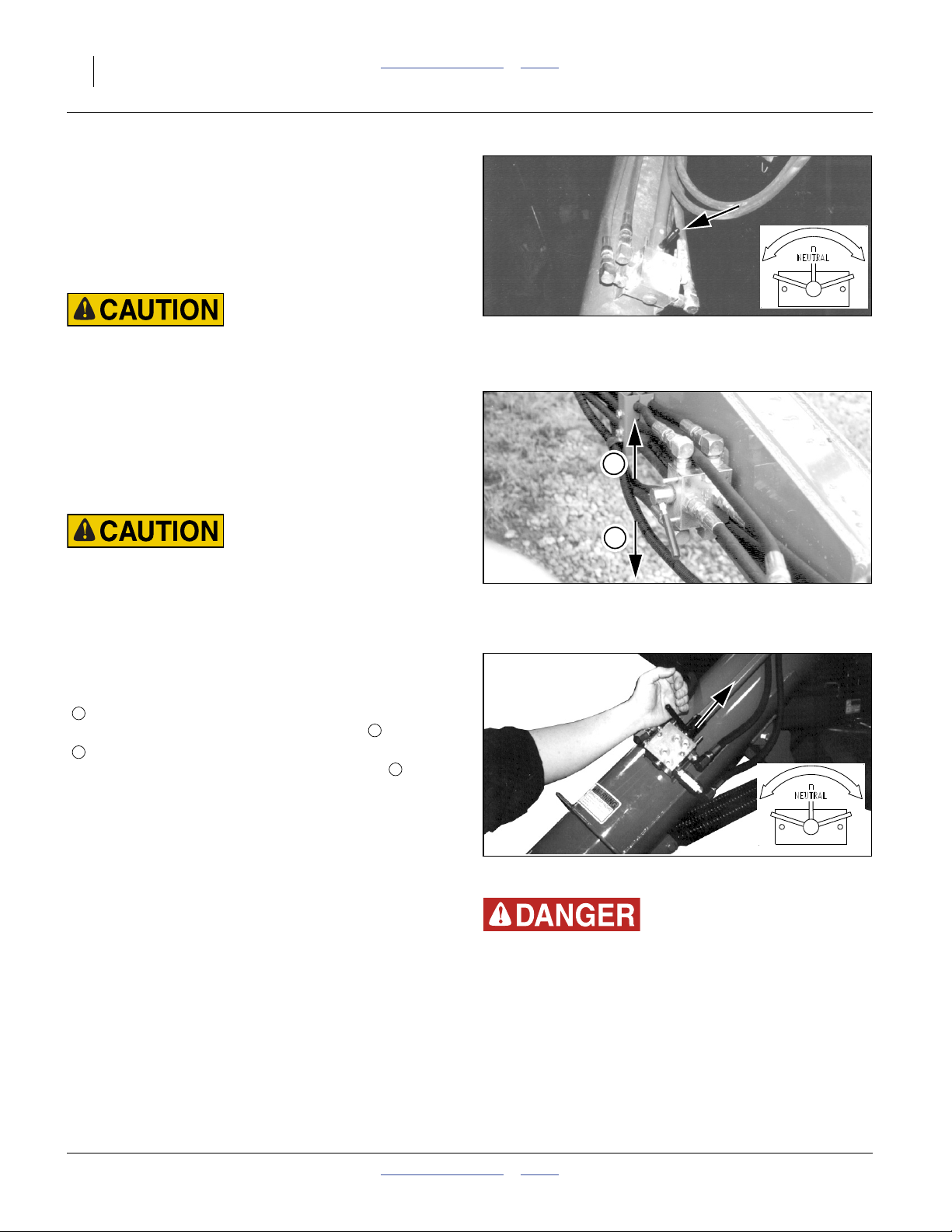
8. Set the auger direction valve to the middle position
for Off.
Diverter Valve
This valve is located on the inside of the left tongue tube.
It selects whether the circuit supplies the auger, or the
trailing implement.
Refer to Figure 15
Do not operate this valve with the hydraulic circuit energized.
Unexpected drill/marker movements or auger rotation can
result.
Do not use this valve as the Start-Stop control for the auger.
Operate the valve with the tractor hydraulic circuit off, or
set to neutral or float. The handle has two positions.
Auger Diverter Valve Positions
U
Handle Up: Marker-enable (make sure other Marker
controls are off before moving handle to ).
D
Handle Down: Auger (make sure Auger control is in
center-off position before moving handle to ).
U
D
Figure 14
Auger Direction Valve Off
U
D
Figure 15
Auger Diverter Valve
16172
16221
Auger Direction Valve
Refer to Figure 16
The valve at the inlet end of the auger tube controls the
direction of auger helicoid screw rotation.This valve is
“center off”.
Figure 16
Auger Direction Valve
14884
12713
To allow flow control by an operator at the outlet end, the
control handle for the valve has an extension and second
handle.
9. Use this valve as the Start-Stop and
Forward-Reverse control for the auger. Set the valve
to center-Off when not moving material at the
moment.
Rotating auger.
To prevent serious injury or death:
▲ Read instructions and safety information before operation.
▲ Keep hands, feet, hair and clothing away from rotating
auger.
▲ Do not remove or modify any guards.
▲ Keep children well clear of work area.
167-073M Table of Contents Index 2012-10-17
Page 27
Great Plains Manufacturing, Inc. Table of Contents Index Operating Instructions 23
Auger Inlet Orientation
During material loading and unloading, a snap pin may
be used to keep the auger inlet hopper upright.
Auger Inner Arm Pin
The auger may also be used to collect material being
unloaded from the hoppers, from beneath the meters
(see “Unloading the Cart” on page 34).
Refer to Figure 18
To allow the inlet to reach under the cart, remove a pin
securing the inner swing arm to the cart frame.
3
Machine Damage Risk:
Be aware of the location of the outlet end of the auger during
positioning. In addition to overhead line hazards, if a trailing
implement is folded, the auger can strike it during positioning,
with possible damage to the auger or implement.
Storing Auger
The auger inlet hopper may be oriented as desired when
stowed, based on road and weather conditions.
1. Orient hopper.
If storing for transport, orient the inlet hopper up and
toward cart center. This protects the auger from
damage from movement of the trailing implement on
uneven terrain, and minimizes collection of debris
thrown by the tire.
If securing the auger for cart storage, orient the inlet
hopper out and down. This minimizes collection of
airborne debris and precipitation. See also
“Storage” on page 37.
2. Fold arm with center pivot forward.
3. Push auger to cradles.
4. Seat auger in cradles.
5. Pin inner arm (if unpinned).
6. Secure rear latch.
Figure 17
Auger Inlet Snap Pin
3
Figure 18
Auger Inner Arm Pin
16116
16101
Auger Swing Arm
The auger arm may be completely unfolded to straight
out, or folded, with the middle pivot pointing to cart front
or back, as needed, to meet your loading or unloading
requirements.
2012-10-17 Table of Contents Index 167-073M
Page 28
24 ADC2220 Table of Contents Index Great Plains Manufacturing, Inc.
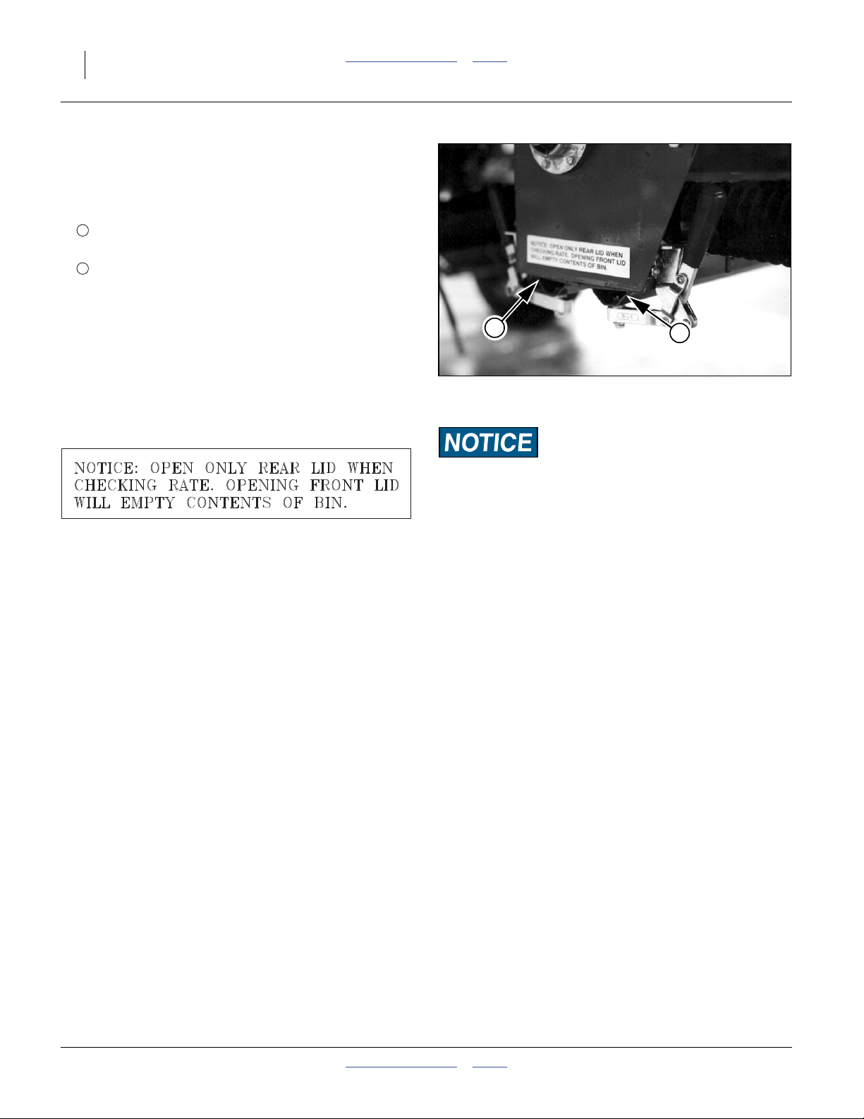
Meter Doors
Refer to Figure 19
Each meter box has two distinct access doors on the
bottom:
1
• Front: Clean-Out
(for emptying hopper)
2
• Rear: Calibration
(for meter sampling and meter clean-out)
The doors are closed during transport, loading and
planting. They may be open slightly in storage if the
hopper was not completely dry at clean-out.
The doors need to close and seal tightly during planting.
Check for leaks with cart fan running. Periodically inspect
the lever clamps for proper tension, and inspect the
elastomer seals for integrity and resiliency.
Meter Door Opening
2
Figure 19
Meter Doors Closed
1
14874
1. Pull out on a clamp handle just until it is loose.
2. Pull out on the other clamp handle. The door
normally will swing down on its own. If not, pull it
open by hand.
Meter Door Closing
Make sure the clamp handles are out or down (not up),
or it will not be possible to close the door.
1. Use a clean rag to wipe any residual material from
the face of the elastomer seals on the door, and from
the bottom face of the meter box.
2. Swing the door up into closed position.
3. While holding the door closed, swing one clamp
handle up, past vertical.
4. Swing the other clamp handle up past vertical.
5. Inspect the door closure for possible air leaks.
Replace any deformed elastomer seal or damaged
latch clamp.
Material Loss Risk:
Do not open the (forward) clean-out door unless preparations
have been made to capture any material to be re-used. Any
material present will flow immediately, possibly in large
volume, as soon as the door is open. Re-closing the clean-out
door, and obtaining an air-tight seal, is usually not possible
until the hopper is completely empty.
167-073M Table of Contents Index 2012-10-17
Page 29

Great Plains Manufacturing, Inc. Table of Contents Index Operating Instructions 25
Meter Hand Crank
A hand crank is provided on the right side of the cart for
manual operation of the meters (the meters otherwise
turn only when the cart is in motion with the clutch
engaged).
The crank is stored in a ring on the frame just aft of the
right lower steps. Place it over the notched end of the
gearbox jackshaft.
Population Risk:
Rotate the hand crank only in the clockwise direction.
Operating in reverse (counter-clockwise) meters material at
incorrect rates (far too low).
The crank is used for two common tasks:
• calibration of the meter setting for planting, and
• clean-out of the meter flute chamber.
Operating the Hand Crank
Turn the hand crank clockwise to simulate meter
operation during planting.
Specific recommendations may be made in applicable
manual sections. See:
see “Meter Calibration” in the Seed Rate manual,
see “Unloading the Cart” on page 34, and
see “Storage” on page 37.
In general, you may operate the crank as fast as is
comfortable.
To shift gearbox and change quick-change and final drive
range gearing see “Meter Rate Adjustment” on
page 66.
Note: If gearbox clutch is disengaged, operating the hand
crank may fail to clear the meters of seed.
Figure 20
Hand Cranking Direction
16115
2012-10-17 Table of Contents Index 167-073M
Page 30
26 ADC2220 Table of Contents Index Great Plains Manufacturing, Inc.
Transport
Electrocution Hazard.
To prevent serious injury or death from electric shock, keep
clear of overhead power lines when transporting, folding,
unfolding or operating all air drill components. Machine is not
grounded. At higher voltages, electrocution can occur without
direct contact.
Great Plains recommends transporting the air cart
without seed loaded. Although designed for highway
movement with full hoppers, the additional weight of
seed may cause the implement assembly to exceed the
rated ability of the tractor, makes the assembly more
difficult to control and stop, and increases wear on cart
tires and wheel bearings.
Loss of Control Hazard:
Towing the drill at high speeds or with a vehicle that is not
heavy enough can lead to loss of vehicle control. Loss of
vehicle control can lead to serious road accidents, injury and
death. To reduce the hazard:
• Do not exceed 20 mph (32 km/h).
• Do not tow an assembly that, when fully loaded,
weighs more than 1.5 times the weight of the towing
vehicle.
In the tables on page 27, the tractor must weight at
least2⁄3(67%) of the weights shown.
The tractor must also be rated for towing and braking
the total load shown.
Minimum Towing Vehicle
To be safe compute the weight of your configuration from
the “Specifications and Capacities” information in each
manual, plus any material data, or have the assembly
weighed at a scale.
Note: The table weights are approximate. Actual
assembly weights can vary by hundreds of pounds
depending on options, openers, material density
and aftermarket equipment.
Note: A loaded seed cart can easily cause the total
assembly weight to exceed 1.5 times (150% of) the
weight of a fully ballasted tractor. Great Plains
recommends transport with the cart empty.
For transport weight of the ADC2220 without an
implement, see “Specifications and Capacities” on
page 107.
167-073M Table of Contents Index 2012-10-17
Page 31

Great Plains Manufacturing, Inc. Table of Contents Index Operating Instructions 27
Approximate Assembly Weights
2012-10-17 Table of Contents Index 167-073M
Page 32

28 ADC2220 Table of Contents Index Great Plains Manufacturing, Inc.
Pre-Transport Checklist
Before transporting the cart, check and observe the
following items.
❑ Make sure the weight of the tractor equals or
exceeds 67% your air drill assembly. Be sure to
include hopper contents if materials are pre-loaded,
and markers. If weights are added to the tractor or
drill, or to reach the tractor-weight figure, make sure
the grand total weight including tractor is still within
the rated capacity of the tractor.
❑ Auger Latch
Properly pin and latch auger to cart and rear storage
arm before transporting.
See “Storing Auger” on page 23.
❑ Hopper Lids
Closed and secured.
See “Lid Closing” on page 20.
❑ Transport Locks
Check that all implement transport locks are securely
in place.
❑ Tires
Check that all tires are properly inflated as listed on
“Tire Inflation Chart” on page 107.
❑ Bystanders
Check that no one is in the way before moving. Do
not allow any one to ride on the cart or implement.
❑ Warning Lights
Always use tractor, cart and implement warning
lights when transporting the air drill.
❑ Clearance
Know the maximum dimensions of the cart and
implement in transport position and follow a route
that provides adequate clearance from all
obstructions, including overhead lines.
See “Specifications and Capacities” on page 107.
❑ Stopping Distance
Allow sufficient stopping distance and reduce speed
prior to any turns or maneuvers. If the cart is
transported full, allow extra stopping distance.
❑ Road Rules
Comply with all national, regional and local laws
when transporting on public roads.
❑ Watch Traffic
The bins obstruct a portion of your rear view. Be
prepared for sudden maneuvers from following
vehicles.
167-073M Table of Contents Index 2012-10-17
Page 33

Great Plains Manufacturing, Inc. Table of Contents Index Operating Instructions 29
Loading Material
Confined Space Entrapment/Suffocation Hazard:
Never enter a hopper for loading or unloading.
Once used for hazardous fertilizer or treated seed, dangerous
concentrations of fumes may be present even in an empty
hopper with the lid open.
Even with small amounts of otherwise harmless material
loaded, the atmosphere inside the hopper may have insufficient
oxygen or high levels of choking dust.
1. Securely hitch cart or drill+cart to a tractor with
adequate weight and power. Park cart on solid, level
ground. See Tractor Requirements, “Specifications
and Capacities” on page 107.
Note: Static tongue weight of a loaded cart is about
5,500 pounds (2500 kg) on level ground and more
when facing downhill.
Refer to Figure 21
2. At each hopper to be loaded, if meter box clean-out
1
door was completely closed, open it. See “Meter
Doors” on page 24. If the cart has been parked for
more than a day, condensation may have caused
moisture to accumulate.
3. Wipe seals and meter bottom flanges clean. Close
and latch clean-out doors.
4. With the cart fan running, check hopper-lid and
meter-box seals carefully for air leaks. Adjust bin
latch or replace seals to prevent leakage.
5. Shut off all hydraulic power to the cart.
+
2
Figure 21
Calibration and Clean-Out Doors
1
14876
Population Risk:
Before first cart use, and at the beginning of each season,
check the entire bin for leaks. A small air leak can cause large
variations in seeding rates.
Refer to Figure 22
6. Set the Auger Direction Valve control handle to
center, off position.
Refer to Figure 23
7. Set the cart diverter valve to the down (Auger)
position. See “Diverter Valve” on page 22.
8. Climb the steps to the cart walkboard. Unlatch and
open the lid. See “Lid Opening” on page 20.
9. Check that the strainer basket is in place in the top of
the bin. Remove any foreign material from the
basket.
2012-10-17 Table of Contents Index 167-073M
Auger Direction Valve Off
Figure 22
U
D
Figure 23
Diverter Valve to Auger
16172
16221
Page 34

30 ADC2220 Table of Contents Index Great Plains Manufacturing, Inc.
10. Unlatch the auger, and swing the inlet end to the
ground. See “Deploying Auger” on page 21.
Machine Damage Risk:
If the trailing implement is folded, mind the outlet end of the
auger, as the auger can strike components of a folded trailing
implement.
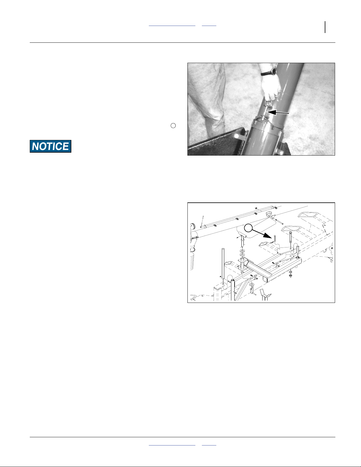
Refer to Figure 24
11. Pull up on the hopper snap pin and pivot the auger
Keep clear of overhead power lines when positioning auger.
hopper until its opening is facing up, and the snap
pin is captured in a locking hole.
12. Swing the auger so the spout is centered over the
hopper opening. Position your grain container for
unloading into the auger hopper.
13. Energize tractor hydraulics for auger. You may need
to tie the control lever in place or adjust the detent
pressure on your tractor.
14. Start the auger by turning the auger direction valve
off center to the left or right. Visually check auger for
correct rotation direction. Reverse handle if needed.
See “Auger Hydraulic Controls” on page 21.
15. Slowly turn on material flow and fill hopper.
Note: When leveled off, the top cone of the bin holds
Figure 24
Auger Inlet Snap Pin
16116
about one-third of bin capacity, the center area
one-third and the lower cone one-third.
16. When hopper is full, turn off the auger by moving the
auger direction control to the center position.
17. Briefly run auger in reverse to return any residual
material to the inlet hopper for recovery or disposal.
12713
18. Return auger to storage position. See “Storing
Auger” on page 23.
19. Turn off the tractor hydraulics.
20. When circuit is off, set diverter to up (pass-through to
markers or fan). See “Auger Hydraulic Controls”
on page 21.
Rotating Auger.
To prevent serious injury or death:
▲ Read instructions and safety information before operation.
▲ Keep hands, feet, hair and clothing away from rotating
auger.
▲ Do not remove or modify any guards.
Do not turn the auger hydraulic diverter handle until the
▲ Keep children well clear of work area
hydraulics have been shut off. If the diverter is moved with
hydraulics on, other equipment may suddenly begin moving.
21. Remove any foreign matter from the strainer basket.
22. Wipe any grain or foreign matter from lid-seal area
on top of cart bin. Close lids and latch securely.
167-073M Table of Contents Index 2012-10-17
Page 35

Great Plains Manufacturing, Inc. Table of Contents Index Operating Instructions 31
Fan Operation
Fan speed is monitored and reported by the seed
monitor, but is manually controlled by the tractor circuit
lever. The optimum rate depends on the seed type, any
treatments. “Fan Speed Adjustment” on page 73 for
further information.
Refer to Figure 25
On newer air carts, there is a fan shut-off valve that must
must be open for the fan to operate.
1. With the tractor at a low idle speed, energize tractor
hydraulics for fan. Lock hydraulic lever in place for
continuous operation. Refer to your tractor operator’s
manual for instructions on operating hydraulic motor.
Always engage the fan with the tractor at a low engine speed.
Engaging the fan when the tractor is at high speed may cause
fan damage.
2. Check that the bottom of the fan rotor rotates toward
the rear of the cart. If not, reverse the direction of the
hydraulic flow from the tractor.
Figure 25
Y1078+ Fan Shut-Off
17172
Do not reverse hydraulic flow with the fan running.
3. Run fan for at least 15 minutes before seeding.
Hydraulic fluid must be warm before fan (and wing
down pressure on some implements) operates
properly.
Refer to Figure 26
The proper reading for the magnehelic air pressure gauge is
12 to 25 inches of water. A sudden drop in pressure is a sign of
a possible leak which can negatively affect seeding.
4. Check bin-lid and meter-box seals for air leaks.
Adjust the latch or replace the seals to prevent
leakage.
Note: It only takes a very small air leak to cause large
variations in the seeding rate and pattern.
Do not exceed a fan speed of 5000 rpm. Set your monitor to
alarm before reaching this speed.
Figure 26
26425
Fan Air Pressure
2012-10-17 Table of Contents Index 167-073M
Page 36

32 ADC2220 Table of Contents Index Great Plains Manufacturing, Inc.
Acremeter Operation
The acremeter, located on the air cart clutch shaft,
counts shaft rotations whenever the shaft is rotating - this
is with the drill lowered and in motion or during
calibration crank operation. The meter is programmed to
display rotations as acres or hectaresa, when using all
rows, factory-specified tires and tire inflations.
Note: Unusual conditions and/or non-standard row
spacings can cause the acremeter tally to vary
from actual acres planted.
Normal Operating Sequence
Note: The acremeter counts rotations during air cart
calibration (and if so, can be useful for calibration).
1. Record the acremeter reading at the start of planting
(and after calibration). The large “12345.6” format
display is the grand total area since meter
installation. The smaller number in the lower left
corner is the number of revolutions per acre for
which the meter was factory-programmed. If the
display is blank, see “Dormant Display” below.
2. Lower air cart and plant. Acremeter counts shaft
rotations, calculates acres or hectares, and adds to
the running grand total.
3. During planting (air cart lowered and moving
forward), the display blanks (goes dormant), but area
tally continues.
4. When raised for turns, obstructions and transport,
the clutch disengages, the shaft stops, and the meter
counts no additional (non-planting) rotations.
5. Whenever shaft rotation stops, the LCD display
activates after 30 to 60 seconds, and remains visible
for 30 to 45 minutes.
6. At the completion of planting, record the final reading
or the grand total. If the display goes dormant before
you can read it, see “Dormant Display”.
7. Subtract the reading at Step 1 from the reading at
Step 6 for the total planted in the present session.
Dormant Display
Refer to Figure 28
To conserve power, the LCD display blanks itself most of
the time. If you need to read the display after it has
“timed out” and gone dormant:
• use the calibration crank to turn the jackshaft once, or
• gently tap or wave a magnet at either of the Great
Plains logo spots on the lower region of the display.
1
Be careful not to scratch the window.
Figure 27
Electronic Acremeter
1
Figure 28
Meter Display (Acres)
27378
29016
a. See page 106 for replacement and alternate meters.
167-073M Table of Contents Index 2012-10-17
Page 37

Great Plains Manufacturing, Inc. Table of Contents Index Operating Instructions 33
Field Operations
This section presumes that all pre-operation checks have
been made on both air cart and drill, the cart is loaded
with seed and any treatments, and the rate has been set
and calibrated.
Rate setting, and gearbox operation, are covered at
“Meter Rate Adjustment” on page 66.
Refer to Figure 29
Seed meter gearboxes are ground driven through an
electric clutch. The clutch is controlled by an implement
lift switch, which is in series with an On/Off switch at
the seed monitor console. The implement must be
lowered, and the console switch must be ON (|) for seed
to meter. This switch also controls valves on NTA drills,
and must be off for folding.
Note: The switch can only override the automatic
metering to Off. It does not engage the clutch if the
implement is lifted.
See “Loup II Monitor Operation” on page 38.
1
Figure 29
Monitor Console and Switch
1
29013
Single Hopper Operation
If materials are being applied from a single bulk hopper,
disengage the gearbox clutch for the other gearbox.This
minimizes wear on the gearbox.
Final Field Checklist
❑ Check tire inflation (page 107).
❑ Check all seed hoses connected.
❑ Check for openers for plugging.
❑ Set seed meters per chart and calibration.
❑ Set seed monitor alarm limits.
❑ Check diverter valve set to implement.
❑ Check fan shut-off valve open (fan enabled)
❑ Set fan to speed suitable for seed. Watch fan at
start-up to ensure correct direction of rotation.
❑ Run fan for at least 15 minutes before planting.
❑ Check air pressure gauge for 12 to 25 inches of
water pressure.
❑ Check for air leaks at lids and meter box seals.
❑ Set electric clutch rocker switch (at console) to On.
❑ Complete drill checklist.
Planting Sequence
1. Lower drill 5 to 10 feet (1.5 to 3 m) before initial
seeding point.
2. Pull forward and begin planting.
3. Raise drill for turns (meters stop automatically - it is
not necessary to use the cab rocker switch).
Planting
Be aware of the 5 to 10 feet (1.5 to 3 m) of drill-lowered
operating distance required for seed to reach the row
units.
If you stop in the middle of a pass, raise the drill and back
up 10 feet (3 m) before resumption of seeding.
Planting Speed
The seed rate charts were developed at a field speed of
6.5 mph (10.5 km/h) using a single hopper, standard
2-star flutes and the seed density shown in the chart.
The chart or calibrated rates also apply to lower speeds.
Higher speeds are possible, particularly with dual hopper
operation and/or optional high-rate flutes. Test to make
sure that material is being delivered at the desired rates,
and that seeding depth is maintained.
At higher speeds, check for signs of:
low seed flow (due to seed cavitation in the meter),
seed plugging (due to fan air flow insufficiency),
row-to-row rate variation (insufficient fan) and;
inconsistent seeding depth (due to opener bounce).
2012-10-17 Table of Contents Index 167-073M
Page 38

34 ADC2220 Table of Contents Index Great Plains Manufacturing, Inc.
Walkboard Steps
The walkboard between the hoppers is served by two
steps, one on each side of the cart.
The lower steps are removable, to allow auger access
under the rear meter box.
1
1
Removing the Left Lower Steps
Refer to Figure 30
If unloading the rear hopper, the lower section of the left
side walkboard steps must be removed for auger access
to the rear meter.
1. Unscrew the two black knobs .
2. Lift the ladder off the cart and store where it cannot
be run over.
3. Screw knobs back into their holes so they will not be
lost.
1
Figure 30
Remove Lower Steps
16151
Unloading the Cart
The cart auger can be swung under the cart to unload
material in hoppers. The material must be in a
free-flowing state.
Chemical Hazard:
Follow manufacturer recommendations for protective
equipment when working with treated seeds.
For normal unloading:
1. Securely hitch cart or drill+cart to a tractor with
adequate weight and power. Park cart on solid, level
ground. See Tractor Requirements, “Minimum
Towing Vehicle” on page 26.
2. Shut off all hydraulic power to the cart.
3. Remove the left side lower steps. See “Removing
the Left Lower Steps”, above.
Electrocution Hazard:
Keep clear of overhead power lines when positioning auger.
Rotating Auger.
To prevent serious injury or death:
▲ Read instructions and safety information prior to operation.
▲ Keep hands, feet, hair and clothing away from rotating
auger.
▲ Do not remove or modify any guards.
▲ Keep children well clear of work area.
167-073M Table of Contents Index 2012-10-17
Page 39

Great Plains Manufacturing, Inc. Table of Contents Index Operating Instructions 35
4. Unlatch the auger and remove the inner arm retainer
pin. See “Deploying Auger” on page 21.
5. Check that the auger directional control on the auger
tube is in the center, neutral/off position. See “Auger
Hydraulic Controls” on page 21.
6. Pull the auger away from the cart. Swing the inlet
under the meter of the cart hopper to be unloaded.
7. As needed, pull up on the auger hopper snap pin
and rotate the auger inlet hopper so that the opening
faces up.
8. Install the calibration crank. It will be used to empty
the flute chamber of the meters. See “Meter Hand
Crank” on page 25.
Figure 31
Hand Cranking Direction
16115
9. Set diverter valve to Auger (See “Auger Diverter
Valve” on page 22).
10. Position your grain container under the auger spout.
11. Start the tractor’s hydraulic system and engage the
12713
circuit for the Auger/Marker. You may need to tie the
tractor control lever in place.
12. Start the auger by turning the auger motor control
left or right. Visually check auger for correct direction
of rotation. Reverse handle if needed.
Refer to Figure 32
13. Slowly open the clean-out door on the bottom of
the meter.
1
2
1
This is the forward of the two doors on the meter.
14. When material flow from the clean-out stops, open
the calibration door to ensure complete clean-out.
2
The calibration door is the rear door.
Figure 32
Calibration and Clean-Out Doors
14876
Refer to Figure 31 on page 35
15. Turn the hand crank clockwise to empty meter. Turn
until material flow is nil.
16. Set the auger directional control to neutral/off.
17. Move auger inlet out from under cart.
18. To empty the other hopper, repeat step 6 to step 17.
2012-10-17 Table of Contents Index 167-073M
Page 40

36 ADC2220 Table of Contents Index Great Plains Manufacturing, Inc.
Unloading Closeout
19. Return hand crank to storage position.
20. If storing at end of season, or having residual
material in the auger tube is a concern, reverse the
directional control on the auger until no seed
remains in the auger tube.
21. Set the tractor circuit for the auger to neutral, or shut
down tractor hydraulics completely.
22. With auger circuit off, set diverter handle back
(pass-through to implement).
Do not move the auger hydraulic diverter valve to the up
(implement) position until the hydraulic circuit has been shut
off at the tractor. If the diverter is moved with hydraulics on,
the drill markers will suddenly begin moving.
23. Clean out auger hopper by pulling up the hopper
snap pin and swiveling the hopper to the side.
24. When empty, fold the auger swing arm (middle pivot
forward), and move it nearly into the cradles.
25. Swivel the auger hopper for transport or storage.
See “Storing Auger” on page 23.
26. Return auger to storage cradle. See “Storing
Auger” on page 23. Secure latch and inner arm
retaining pin.
27. Re-install lower steps (page 34).
28. Wipe top and bottom of meter-box seal flanges,
making sure all material is removed. Look for
material caught between seal and flange.
29. Close clean-out and calibration doors.
167-073M Table of Contents Index 2012-10-17
Page 41

Great Plains Manufacturing, Inc. Table of Contents Index Operating Instructions 37
Parking
Follow these steps when parking the drill for periods of
less than 36 hours. For longer periods, see Storage, the
next topic.
1. Place the cart on firm, level ground.
2. Check that hopper lids are latched, and secure the
hopper lids with security cable or padlock and chain
to prevent entry by children. See “Lid Closing” on
page 20.
3. Remove jack from storage position and pin securely
to lifting stob on outside of cart tongue. See
“Hitching” on page 14.
4. If ground is soft place a wide block or plate under the
jack to increase contact area.
5. Securely block cart tires to prevent rolling.
6. Extend jack until weight is off of the tractor drawbar.
7. Unhook electrical lines and install plugs as provided.
8. Release pressure on hydraulic system, then
disconnect hydraulic lines and pull all lines back onto
cart tongue. Be sure hose ends do not rest on the
ground.
9. Disconnect the safety chain.
10. Unhitch from tractor.
Storage
If possible, leave the air cart and drill connected for
extended storage. Store the air cart and drill where
children do not play. If possible, store inside for longer
life.
1. Unload all material in hoppers. See “Unloading the
Cart” on page 34.
2. Unlatch the hopper lids so that the seals are not in
compression during storage. Use a chain or security
cable to prevent entry, and prevent high winds from
opening the lid.
3. Empty the hoppers completely. Hand crank the
meters several turns to empty completely. See
“Meter Hand Crank” on page 25. Blow out the
meters with air to remove all material.
4. Unless cleaned out at last loading or during unload
above, deploy the auger, and run the motor in
reverse until auger is completely empty. See “Auger
Operations” on page 21.
5. Return the auger to its cradle with the inlet hopper
facing down. See “Storing Auger” on page 23.
6. Remove the drive chains and store in oil.
7. Lubricate the cart at all points listed under
“Lubrication and Scheduled Maintenance” on
page 99.
8. Check all bolts, pins, fittings and hoses. Tighten,
repair or replace parts as needed.
9. Check all moving parts for wear or damage. Make
notes of any parts needing repair before the next
season.
10. Open the meter-box doors completely to release
seal pressure and allow rinse water to exit.
11. Thoroughly wash the hoppers with water inside and
out to prevent corrosion from fertilizer or seed
treatments.
12. Set doors to slightly open, but not wide enough for
pests to enter the meters. Wire doors in place if
needed. Do not store cart with seals compressed.
13. If the cart is disconnected from the implement for
storage, plug all 21⁄2inch openings to prevent pests
from nesting.
14. Use touch-up paint to cover scratches, chips and
worn areas to prevent rust.
2012-10-17 Table of Contents Index 167-073M
Page 42

38 ADC2220 Table of Contents Index Great Plains Manufacturing, Inc.
Loup II Monitor Operation
The Great Plains Drill Monitor by Loup Electronics is
designed to provide fan speed, shaft rpm, hopper level,
and seed flow information for conventional and air drills.
This manual section covers operation and calibration.
See also “Install Loup II Console” on page 115 and
“Initial Loup-II Setup” on page 116.
All functions are covered in this section but may not be
applicable to your system configuration.
The monitor is capable of monitoring and displaying:
• Ground speed (implement-mounted speed sensor)
• Fan speed
• Two shaft speed RPM’s (Front and Rear)
• Seed Flow (up to 112 sensors can be connected)
• Field Area
• Total area
• Two Hoppers (displayed as bar graph display)
Figure 33
Loup-II Monitor Console
1
29013
Normal Start-up
For everyday operation the Great Plains drill monitor
remembers all settings that have been saved from the
previous use.
Refer to Figure 34
To turn on the console, press the power button in the
lower right hand corner.
The rocker switch to the right of the console is for
enabling or disabling air cart clutch power. It can be left
off for most console setup operations. It needs to be
on for speed calibration (page 57), and needs to be
off for NTA folding (see NTA Operator Manual).
“Wait For Sensors to Complete Calibration” appears.
During this time the monitor is checking all connected
sensors to ensure they are working properly. Once this
“self-test” is complete the monitor displays the normal
operate screen (next page).
Figure 34
Console Power-On
29023
167-073M Table of Contents Index 2012-10-17
Page 43

Great Plains Manufacturing, Inc. Table of Contents Index Loup II Monitor Operation 39
Normal Operate Screen
Refer to Figure 35
The Normal Operate Screen is divided into the following
areas:
• 2 - Display Sections or 1 enlarged Display Section
(User Chosen)
• 1 - Active alarm window or, if there are no active
alarms, the current ground speed is displayed
• 1 - Bin level icon window
• 2 - Soft-key label windows
Below is a sample screen:
Top Display
Active Alarm
Display
Soft Key Windows
Figure 35
Console Display Regions
In the Sample Normal Operate Screen above, the different areas are as follows:
• The Top Display Section is the window with “Field Area” in it.
• The Bottom Display Section is the “Fan Speed” window.
• The active alarm window has the Ground Speed “88.8 MPH” displayed on it.
• The Bin Level Window is shown as 3 graphics:
F shows a full hopper
R shows an empty hopper
• The soft key windows are displaying “Menu” and “Enlarge”.
Bottom Display
Bin Level
Display
29024
2012-10-17 Table of Contents Index 167-073M
Page 44

40 ADC2220 Table of Contents Index Great Plains Manufacturing, Inc.
Changing Display Size
Depending on the preference of the operator, the Bottom
display of the Loup II can be enlarged to make viewing
easier.
Refer to Figure 36
To change the display size press the bottom button
labeled ENLARGE.
Refer to Figure 37
Notice the button label now reads SMALLER. To return
to the smaller screen press the bottom button labeled
SMALLER.
Figure 36
Small Operate Screen
Figure 37
Large Operate Screen
29025
29026
167-073M Table of Contents Index 2012-10-17
Page 45

Great Plains Manufacturing, Inc. Table of Contents Index Loup II Monitor Operation 41
Changing Displayed Functions
Refer to Figure 38 and Figure 39
The display of the Great Plains monitor can be changed
to show any of the available functions the operator
chooses.
Pressing either the UP arrow or the DOWN arrow button
while at the normal operate screen allows you to pick
from a list of the available functions.
Pressing the UP arrow changes the Top Display,
pressing the DOWN arrow changes the Bottom Display.
Note: The sample procedure on the next page is based
on the UP arrow being pressed. The procedure is
the same when the DOWN arrow is pressed
Figure 38
For Top Display Use Up Arrow
Figure 39
For Bottom Display Use Down Arrow
29027
29028
2012-10-17 Table of Contents Index 167-073M
Page 46

42 ADC2220 Table of Contents Index Great Plains Manufacturing, Inc.
Refer to Figure 40
In this sample we change the top display from reading
Field Area to Shaft RPM.
Having pressed the UP arrow in the Normal Operate
screen, a menu screen titled “Top Display Section”
appears. The current displayed function is highlighted. In
this sample Field Area was shown in the top display thus
Area is highlighted.
Refer to Figure 41
Press the UP arrow until “Shaft RPM” is highlighted.
(Depending on your system set-up, some of the options
shown may not be available.)
Press the softkey under “SELECT” when “Shaft RPM” is
highlighted.
Figure 40
Select Function with Up Arrow
Figure 41
SELECT a Function
29029
29030
167-073M Table of Contents Index 2012-10-17
Page 47

Great Plains Manufacturing, Inc. Table of Contents Index Loup II Monitor Operation 43
Refer to Figure 42
The “Shaft RPM” menu is displayed.
The “Shaft RPM” menu provides two options to choose
from.
• Front - Displays front shaft RPM
• Rear - Displays rear shaft RPM
Refer to Figure 43
For this example use the DOWN arrow button to highlight
“Rear”.
Press SELECT
Figure 42
A Sub-Menu
Figure 43
Selecting a Sub-Menu Item
29031
29032
2012-10-17 Table of Contents Index 167-073M
Page 48

44 ADC2220 Table of Contents Index Great Plains Manufacturing, Inc.
Refer to Figure 44
The display returns to the Normal Operate screen.
Notice that the Top Display now reads Rear Shaft RPM.
Alarms
The alarm display becomes active when any conditions
fall below the set alarm points. For example: Low Fan
Speed, High Fan Speed, Low Hopper Level, No Ground
Speed, Low Seed Flow.
All alarms operate in a similar fashion:
An audible alarm sounds and
an alarm message appears on the display.
This alarm display is only active when the monitor is at
its normal operating screen.
Pressing “OK” silences all alarms. All acknowledged
alarms are displayed on the normal operating screen
active alarm window until the alarm condition is fixed.
Sample alarm screens are shown below.
Should be Seeding
Refer to Figure 45
Should be Seeding alarm indicates that the implement
has been out of motion for more than 30 seconds.
Figure 44
Normal Operating with New Item
Figure 45
Alarm: Should Be Seeding
29033
29034
167-073M Table of Contents Index 2012-10-17
Page 49

Great Plains Manufacturing, Inc. Table of Contents Index Loup II Monitor Operation 45
Refer to Figure 46
On pressing OK, the display returns to the normal
operating screen, with the acknowledged
“Should be seeding” Alarm displayed in active alarm
window.
Low Fan Speed
Refer to Figure 47
A Low Fan Speed alarm occurs when the Fan Speed has
fallen below the set alarm point. The cause of the
problem must be resolved on the machine. A similar
alarm occurs for excessive fan speed.
Figure 46
Acknowledged: Should Be Seeding
Figure 47
Alarm: Low Fan Speed
29035
29036
2012-10-17 Table of Contents Index 167-073M
Page 50

46 ADC2220 Table of Contents Index Great Plains Manufacturing, Inc.
Empty Bin
Refer to Figure 48 and Figure 49
An Empty Bin alarm occurs when the grain in the hopper
has fallen below the hopper sensor indicating that the
hopper is near empty.
An Empty Bin alarm only occurs if your system is
equipped with hopper level sensors.
Figure 48
Alarm: Empty Bin
Figure 49
Acknowledged: Empty Bin
29037
29038
167-073M Table of Contents Index 2012-10-17
Page 51

Great Plains Manufacturing, Inc. Table of Contents Index Loup II Monitor Operation 47
Blockage Module
Two different Blockage Module alarms may occur.
Refer to Figure 50 and Figure 51
Blocked
Blockage Module Run 1 is Blocked indicates the
displayed row has stopped seeding and should be
cleaned.
When acknowledged, the alarm appears in the active
alarm window of the normal operating screen.
Figure 50
Alarm: Blockage
Figure 51
Acknowledged: Blockage
29039
29040
2012-10-17 Table of Contents Index 167-073M
Page 52

48 ADC2220 Table of Contents Index Great Plains Manufacturing, Inc.
Bad
Refer to Figure 52 and Figure 53
Blockage Module Run 1 is Bad indicates the displayed
row has stopped and has failed the self test. This does
not mean the sensor is bad!
When acknowledged, the alarm appears in the active
alarm window of the normal operating screen.
Run a blockage calibration as shown on page 62. If the
indicated sensor will not calibrate, the sensor should be
replaced.
Figure 52
Alarm: Blockage Sensor
Figure 53
Acknowledged: Bad Sensor
29041
29042
167-073M Table of Contents Index 2012-10-17
Page 53

Great Plains Manufacturing, Inc. Table of Contents Index Loup II Monitor Operation 49
Communication Error
Refer to Figure 54 and Figure 55
A Communication Error occurs any time the monitor
loses communication with a learned sensor. This
includes Ground Speed, Shaft, Fan Speed, Hopper
sensors and Blockage Modules.
If a communication error is received:
• Check that all harness connections are securely
connected.
• If no loose connections are found, check all wiring to
ensure the wires have not been broken.
If any of the listed alarms persist or if an alarm is
displayed that is not listed contact your Great Plains
dealer.
When acknowledged, the alarm appears in the active
alarm window of the normal operating screen.
Figure 54
Alarm: Communication Error
Figure 55
Acknowledged: Communication
Error
29043
29044
2012-10-17 Table of Contents Index 167-073M
Page 54

50 ADC2220 Table of Contents Index Great Plains Manufacturing, Inc.
Special Start-up
Refer to Figure 56
A special start-up screen appears when the monitor is
turned on in the following circumstances:
1. The monitor has been learned but is unplugged from
the drill.
2. The monitor has been learned but has lost its
memory.
3. The monitor has not been learned.
• System Start-up: Selected for “Normal Operation”.
The last used system configuration and settings are
loaded.
• Learn New System: Special start-up used to learn all
new sensors while keeping the previous system
settings.
• Default Settings: Special start-up used to reset all
sensor settings to their default setting.
• Learn New System and Default Settings: Complete
reset of the monitor. Removes all learned sensors and
restores all the default sensor settings.
If this screen appears and you are unsure of what to do
contact your Great Plains dealer.
Learn New System
The learn mode is a one time process that identifies
each sensor with the monitor.
Figure 56
Special Start-Up Screen
29045
167-073M Table of Contents Index 2012-10-17
Page 55

Great Plains Manufacturing, Inc. Table of Contents Index Loup II Monitor Operation 51
Refer to Figure 58
Before entering the Learn Mode, be sure to unplug all
the sensors that have a 3-pin connector, i.e. Ground
Speed Sensor, Shaft Sensors, Hopper Sensors,
Population Sensors & Blockage Modules. (Blockage
Sensors have a 2-pin connector and can be plugged into
their appropriate connection on the blockage harness.)
Procedure
1. Press the Power Button to turn the monitor on.
Refer to Figure 57
2. Press the DOWN arrow to highlight Learn New
System and Default Settings
5
0
INCHE
S O
F
W
A
TER
10
15
20
MAGNEHELIC
25
FAN SPEED
BIN
LEVEL
FRONT
METER
Figure 58
Startup: Learn New System
GROUND
BIN
LEVEL
SPEED
METER
REAR
IMPLEMENT
29046
TO
Figure 57
16206
Cart Sensor Locations
2012-10-17 Table of Contents Index 167-073M
Page 56

52 ADC2220 Table of Contents Index Great Plains Manufacturing, Inc.
Refer to Figure 59
3. Press SELECT
Refer to Figure 60
4. An “Are you sure?” prompt appears before the
sensor scan begins. Press the softkey under
CANCEL to exit, or SELECT to reset system settings
and begin scan.
Figure 59
Select Learn New System
Figure 60
Begin Learn New System
29047
29048
167-073M Table of Contents Index 2012-10-17
Page 57

Great Plains Manufacturing, Inc. Table of Contents Index Loup II Monitor Operation 53
Refer to Figure 61
5. Plug each sensor in as the monitor asks for them. If
the sensor is the correct type, it is immediately
recognized, the console beeps, and moves on to the
next sensor.
The first sensor the monitor looks for is a Fan sensor.
This is an implement-mounted sensor monitoring a shaft.
Plug it in now.
If the requested sensor is not mounted on the drill, use
the arrow keys to highlight “Skip this Sensor”, and press
SELECT.
Once the speed sensor has been accepted or skipped,
the monitor moves to the next sensor. The order the
monitor asks for sensors is:
a. Fan
b. Front Shaft
c. Front Bin
Figure 61
Begin Learn New System
29049
d. Rear Shaft
e. Rear Bin
f. Speed
g. Blockage Module 1 through 8
Refer to Figure 62
Note: If during the Learn Mode you receive a
Wrong Sensor Type for:
message, the monitor is detecting a type of sensor
that is incorrect for this function. For example: This
message would appear if monitor asks for Front
Shaft but a hopper sensor is plugged in.
Figure 62
29050
Sensor Type Error
2012-10-17 Table of Contents Index 167-073M
Page 58

54 ADC2220 Table of Contents Index Great Plains Manufacturing, Inc.
Refer to Figure 63
6. When all sensors have been plugged in or skipped,
the monitor displays Installation Complete.
7. Press SELECT.
The monitor displays the Normal Operate Screen.
Note: It is recommended that you turn the monitor off and
back on to ensure the Learn Mode was completed
properly. If the Startup Menu appears when the
monitor is turned on, check that the monitor has not
been disconnected from the harness. If a sensor
Missed or Wrong Sensor Type for message
appears, check that all harness connections are
secure. If no connections are unplugged it may be
necessary to Re-Learn the system.
If problems persist, contact your Great Plains dealer.
System Settings
Refer to Figure 64
Pressing the MENU button on the Normal Operate
Screen accesses your system settings.
Use the DOWN arrow to highlight the desired menu.
Press the SELECT button to enter the selected menu
item.
Review and change these settings as necessary.
All new systems must have the proper implement width and
ground speed to give accurate readings. A Ground Speed
Calibration must be done on all new systems (see page 57).
Systems that include blockage sensors must perform a
Blockage Calibration (See page 62)
Figure 63
Sensor Scan Complete
Figure 64
Settings Menu
29051
29052
167-073M Table of Contents Index 2012-10-17
Page 59

Great Plains Manufacturing, Inc. Table of Contents Index Loup II Monitor Operation 55
Installation
Refer to Figure 65
Install New System
Install New System allows you to overwrite the existing
Sensor setup. Refer to page 51 for information on
Learning a new system.
Replace a Sensor
Replace a Sensor allows you to replace a bad sensor
without re-learning the system. This refers only to
Learned Sensors; i.e. shaft sensors, hopper sensors, fan
speed sensors and blockage modules.
Add a Sensor
Add a Sensor allows you to add a new sensor without
re-learning the system. This refers only to Learned
Sensors; i.e. shaft Sensors, hopper sensors, fan speed
sensors and blockage modules.
Remove a Sensor
Remove a Sensor allows you to remove a sensor from
your existing system without re-learning the system. This
refers only to Learned Sensors; i.e. shaft Sensors,
hopper sensors, fan speed sensors and blockage
modules.
Figure 65
Installation Tasks
29053
2012-10-17 Table of Contents Index 167-073M
Page 60

56 ADC2220 Table of Contents Index Great Plains Manufacturing, Inc.
Implement Setup
Factory defaults for the following settings are very likely
to be incorrect for your drill. Review and set these values
before calibrating or planting.
Refer to Figure 66
Units
The Units setting changes the units of measure that the
monitor accepts as input, calculates and displays.
Note: If you change Units, existing settings are converted
to the new units, excepting Speed Calibration
course length, which remains 400 feet (121.9 m).
• Imperial: (U.S. customary)
U.S. Survey Acres / Feet / Miles per Hour
• Metric:
Hectares / Meters / Kilometers per Hour
Implement Width
Refer to table at right
Adjust to the size of your drill. The factory default of
40.0 feet (1219 cm) is only approximately correct for
40 foot (12.2 m) drills.
Clear Field Area
Use to zero or clear your Field Acres.
Clear Total Area
Use to zero or clear your Total Acres.
Figure 66
Implement Setup
Widtha (Swath)
Imperial
ADI334-3512 35.0 (feet) 10.7 (m)
ADI334-4010 33.3 (feet) 10.2 (m)
ADI334-5507 32.1 (feet) 9.8 (m)
ADI345-4512 45.0 (feet) 13.7 (m)
ADI345-5510 45.8 (feet) 14.0 (m)
ADI345-7507 43.8 (feet) 14.0 (m)
CTA4000-5010 40.6 (feet) 12.4 (m)
CTA4000-6575 40.6 (feet) 12.4 (m)
CTA4000-8006 40.5 (feet) 12.4 (m)
CTA4000HD-5010 40.6 (feet) 12.4 (m)
CTA4000HD-6575 40.6 (feet) 12.4 (m)
CTA4000HD-8006 40.5 (feet) 12.4 (m)
NTA3010-3610 30.3 (feet) 9.2 (m)
NTA3010-4875 30.3 (feet) 9.2 (m)
NTA3510-4010 33.7 (feet) 10.3 (m)
NTA3510-5575 34.7 (feet) 10.6 (m)
a. For implements not listed, measure between
outside end row units, plus one row space.
b. Use “Imperial” for U.S. customary units.
b
29054
Metric
167-073M Table of Contents Index 2012-10-17
Page 61

Great Plains Manufacturing, Inc. Table of Contents Index Loup II Monitor Operation 57
Speed Settings
Refer to Figure 67
Pulses Per Rev
Pulses per Rev (revolution) are the number of magnets
the implement mounted speed sensor sees in one
revolution of the ground drive clutch shaft. The magnet
assembly is on the inner end of this shaft.
The factory default is 4 pulses per rev (PPR), which is
correct for current ADC2220 carts. Older carts may have
2 or 4 magnets on the shaft, visible as short metal rods
in the polymer magnet housing.
Wheel Pulses Per 400 Feet
This is the ground speed calibration number for a
implement mounted speed sensor. Refer to page 57 for
calibration instructions.
The factory default for speed PPR is:
252
for compatibility with older monitors as a service
replacement. This is approximately correct only for
ADI334.
Approximate PPR values for various drills are shown in
the table at right. Do not rely on these values for planting.
Use them as a cross-check of your calibrated rate. If your
calibrated PPR is significantly different from the table, it
may indicate a mechanical fault, or that your cart is not
correctly setup for your drill.
Speed calibration is necessary for all air drills, including
ADI334. The default PPR is incorrect for newer drills, and
the table values at right are only approximate.
Re-calibration is recommended as tires wear or field
conditions change (which can alter effective rolling radius
of tires). Always cross-check the monitor reported speed
with the tractor speedometer or other reference.
Speed Calibration
All new systems require a ground speed calibration to
ensure accurate area totals and accurate ground speed
readings. To complete the calibration, measure a course
400 feet (121.9 m) long preferably on level ground with a
start and finish point. The drill must be in the down
position throughout this procedure.
Refer to Figure 68
1. Position the drill at the start of the course, in lowered
field position. Set clutch switch to On.
1
Note: During the calibration the monitor is looking for the
number of pulses produced from the drill mounted
sensor or in the case of radar, the number of radar
pulses. The monitor does not display 400 when the
speed calibration is complete rather it displays the
pulses counted in 400 feet.
Figure 67
Speed: Pulses per Revolution
Pulses per Rev (Speed) in 400 feet (121.9 m)
Imperial
a
ADI334 253 253
ADI345 331 331
CTA4000 296 296
CTA4000HD 296 296
NTA3010 226 226
NTA3510 253 253
a. Use “Imperial” for U.S. customary units.
Figure 68
Clutch Switch On
29055
Metric
1
29013
2012-10-17 Table of Contents Index 167-073M
Page 62

58 ADC2220 Table of Contents Index Great Plains Manufacturing, Inc.
Speed Calibration Procedure:
Refer to Figure 69
2. From the Speed Settings menu, highlight Speed
Calibration and press SELECT.
Refer to Figure 70
3. Press SELECT again to begin counting pulses.
Figure 69
Select Speed Calibration
Figure 70
Begin Speed Calibration
29056
29057
167-073M Table of Contents Index 2012-10-17
Page 63

Great Plains Manufacturing, Inc. Table of Contents Index Loup II Monitor Operation 59
Refer to Figure 71
4. The display prompts with
“Start Driving”.
Pull forward at normal planting speed. As you drive,
“Wheel Pulses Received”
count up from 0.
Refer to Figure 72
5. At the end of the course, press the SELECT softkey
to save the pulse count as the new
“Pulses per 4000 ft”.
Figure 71
Speed Cal: Start Driving
Figure 72
Speed Cal: Course Completed
29058
29059
2012-10-17 Table of Contents Index 167-073M
Page 64

60 ADC2220 Table of Contents Index Great Plains Manufacturing, Inc.
Refer to Figure 73
6. The display is now back at the Speed Settings Menu.
Notice the
Wheel Pulses Per 400 feet
has changed to the calibrated number.
(The number shown is for illustrative purposes only).
Bin Settings
Refer to Figure 74
Bin Settings allow the operator to Enable and Disable the
alarms for Hopper Level Sensor.
By default, these are set to Enable when Hopper
Sensors are Learned.
If your system does not include hopper sensors, this
menu is not available.
Figure 73
New Speed Cal Saved
Figure 74
Configure Bin Alarms
29060
29061
167-073M Table of Contents Index 2012-10-17
Page 65

Great Plains Manufacturing, Inc. Table of Contents Index Loup II Monitor Operation 61
Meter Shaft Settings
Refer to Figure 75
Front and rear meters have separate settings for sensor
setup and alarms.
Pulses per rev is normally the same for both meters,
except when disabling the sensor for an unused meter.
Alarm limits are typically different for each meter if
different materials are being applied.
Pulses per Rev (Meter)
Refer to Figure 76
Pulses per Rev (revolution) are the number of magnets
the associated sensor sees in one revolution of the shaft
being monitored.
The factory default is 2, which is correct for new
ADC2220 carts.
Changing this number to 0 turns the sensor OFF.
Low Alarm Point
The Low Alarm Point is set as a reference point for the
alarm. If the shaft turns slower than this designated
point, an alarm sounds.
High Alarm Point
The High Alarm Point is set as a reference point for the
alarm. If a shaft turns faster than this designated point,
an alarm sounds.
Figure 75
Shaft Settings Top Menu
Figure 76
Front Shaft Settings
29062
29063
2012-10-17 Table of Contents Index 167-073M
Page 66

62 ADC2220 Table of Contents Index Great Plains Manufacturing, Inc.
Blockage Module Settings
Refer to Figure 77
The Blockage Module Settings only affect those systems
with Blockage Sensors (single sided sensor detecting
seed flow only). A blockage module is a box mounted to
the frame of the drill that blockage sensors are
connected to.
Note: If the menu shows
Number of Modules 0,
this indicates that there are no blockage modules
or sensors being used with the current system.
Runs per Module Setup
The Runs per Module setting adjusts the number of
Blockage Sensors connected to the selected module.
The factory default is:
16
Individual Runs Setup
The Individual Runs Setup allows you turn specific
blockage sensors on (Enable) and off (Disable).
The factory default is:
Enabled (all rows are on)
Blockage Module Test
The Blockage Module Test is used to check
communication between monitor and modules.
Blockage Calibration
A blockage calibration must be done for proper operation
of the blockage sensors. This procedure should be done
when changing seed rates or seed varieties, such as
from Soybeans to Wheat.
Blockage Calibration Procedure:
Refer to Figure 78
1. Enter Blockage Calibration mode by highlighting
Blockage Calibration and pressing the SELECT
softkey.
Figure 77
Blockage Setup
29064
Figure 78
29065
Enter Blockage Calibration
167-073M Table of Contents Index 2012-10-17
Page 67

Great Plains Manufacturing, Inc. Table of Contents Index Loup II Monitor Operation 63
Refer to Figure 79
2. Begin planting a normal speed. You must be planting
seed during this entire process.
Refer to Figure 80
3. As you drive the display shows the number of rows
that have been calibrated on the second line (none
so far in the figure). The third line shows the Total
number of rows.
Note: The number 32 is for illustration purposes only.
Your number will be different.
Figure 79
Begin Planting
Figure 80
Rows in Calibration
29066
29067
2012-10-17 Table of Contents Index 167-073M
Page 68

64 ADC2220 Table of Contents Index Great Plains Manufacturing, Inc.
Refer to Figure 81
4. When the Calibrated row equals the Total Calibration
is complete.
Press SELECT to Exit.
Global Settings
Refer to Figure 82
Volume/Pitch
Volume/Pitch adjusts the sound of the audible alarm.
The range is 0 to 100%.
Factory default is:
50%
Backlight
Backlight adjust the brightness of the display.
The range is 0 to 100%.
Factory default is:
50%
Contrast
Contrast adjust the contrast of the display.
The range is 0 to 150%.
Factory default is:
100%
Figure 81
Blockage Calibration Complete
Figure 82
Global Settings
29068
29069
167-073M Table of Contents Index 2012-10-17
Page 69

Great Plains Manufacturing, Inc. Table of Contents Index 65
Adjustments
To get full performance from your air cart, you need an
understanding of all component operations, and many
provide adjustments for optimal field results. Some of
these have already been covered earlier in this manual.
Even if your planting conditions rarely change, some of
these items need periodic adjustment due to normal
wear.
Adjustment Page The Adjustment Affects
ADC2220 Sprocket Sizes 114 Matching published seed rates
Leveling Cart 15 Planting consistency
Seed Monitor Configuration 116, 119 Correct application rate reporting, useful alarms.
Quick-Change Sprockets 68 Seed population or fertilizer rate (coarse control)
Meter Box Gears 68 Seed population or fertilizer rate (coarse control)
Gearbox Shift Levers 68 Seed population or fertilizer rate (fine control)
Meter Calibration 69 Achieving desired application rate
Changing Meter Flutes 72 Using high rate charts in the Appendix of the Seed Rate manual
Fan Speed Adjustment 73 Consistent seed population and minimum seed damage
Electric Clutch Height Switch Imp.
Chain Slack 96 Reliable operation and minimum wear
a. Refer to implement Operator Manual.
a
Avoiding wasted and unplanted seed
2012-10-17 Table of Contents Index 167-073M
Page 70

66 ADC2220 Table of Contents Index Great Plains Manufacturing, Inc.
Meter Rate Adjustment
Check Flute Shaft Configuration
Refer to Figure 83
(which depicts a single flute “star” with its halves, a single star
mated, two stars staggered, small seeds, and a filler)
Know your “stars” (dosing roller) setup. If your air cart
has never been changed from factory standard, you have
meter flute shafts with two deep-flute “stars” (4 halves)
per outlet. How many “stars” you have determines which
rate to use.
Refer to Figure 84 (depicting an inspection from below meter)
If the configuration is not known, inspect the flute shaft
from the hopper lid (if hopper empty), or from below the
meter, with the calibration door fully open. It is not
necessary to remove the shaft. Inspect the flutes , and
filler rings at active outlets.
On a standard “2 star” shaft, each seed drop outlet
contains two flute sets (4 halves), each pair staggered
slightly from the next. Unused outlets are fully blocked by
filler rings .
On an optional “3 star” shaft, each outlet contains 3 flute
sets of the deep style .
On an optional “4 star” shaft, each outlet contains 4 flute
sets of the deep style , with no fillers between adjacent
drops.
On an optional Small Seeds shaft, each outlet contains
one set of narrow, shallow flutes .
To change meter flutes, see “Changing Meter Flutes”
on page 72.
3
4
1
1
2
1
1
1
Figure 83
Flute Stars and Filler
1
3
Figure 84
Checking Flute Shafts
3
2
32400
4
26426
167-073M Table of Contents Index 2012-10-17
Page 71

Great Plains Manufacturing, Inc. Table of Contents Index Adjustments 67
Find Your Chart and Rate
The rate charts in this manual, starting on page 75 are
based on metering from a single hopper, and the factory
standard “2 star” meter flute configurations.
If metering the same material from both hoppers at the
same time, the actual rate is twice the chart rate:
dual hopper metering: rate is 2× higher than chart.
Example:
Both hoppers operating, and both set for 100 lbs/ac.
The total applied material is 100+100 = 200 lbs/ac.
If you have installed high rate flutes sets, adjust the
rates, in pounds/acre or kilograms/hectare, as follows:
3 stars: material rate is 1.5× higher than chart,
4 stars: material rate is 2× higher than chart
Small Seeds: material rate is1⁄4 of the chart rate.
If using dual hopper and alternate flutes, actual rates are
3×, 4× or1⁄2 chart rates.
If you are planning to apply two different materials (such
as seed and fertilizer) in each hopper, perform the setup
steps separately for each hopper, as the configurations
(including stars) may be completely different.
1. Confirm that the chart is for the material.
2. Find your target population or application rate.
Meter Rate Adjustment
Each meter box is set independently. Unless one is not
used, both need to be set for their material and rate.
Material rate is determined by:
• Quick Change Sprockets
• Meter Box Gears
• Gearbox Shift Level
The Seed Rate Manual charts are based on cleaned
untreated seed of average size and test weight. Many
factors affect meter rates including foreign material, seed
treatment, seed size, field conditions, and test weight.
Minor adjustments will be needed to compensate for
these factors. Initially set the rates according to the
charts, then calibrate for your material and conditions.
Target Rate Adjustments
Hoppers for This Material
Single Dual
2 Stars (std) Rate is 1× Chart
Use chart rate
3 Stars Rate is 1.5× Chart
Lookup 0.67×
4 Stars Rate is 2× Chart
Lookup 0.5×
Small Seeds Rate is1⁄4Chart
Lookup 4×
To find the initial chart rate
Rate is 2× Chart
Lookup 0.5×
Rate is 3× Chart
Lookup 0.33×
Rate is 4× Chart
Lookup 0.25×
Rate is1⁄2Chart
Lookup 2×
AdjustedRate FieldRate LookupFactor×=
In the example, the desired field rate was 200 lbs/ac.
100 = 200 × 0.5
Lookup settings for 100 pounds/acre in the charts.
Initially set each meter for a 100 pounds/acre rate, and
calibrate.
Material Rate Risk:
The adjustment factors above are approximate, and are merely
starting (test) values. You must calibrate (page 69) for
accurate field results. The Small Seeds lookup factors, for
example, vary from 3× to 5.5× depending on seed variety,
meter rate and seed treatments.
2012-10-17 Table of Contents Index 167-073M
Page 72

68 ADC2220 Table of Contents Index Great Plains Manufacturing, Inc.
Quick-Change Sprockets
These are a single pair of sprockets, one 20T, one 30T,
which are exchanged between the (upper) DRIVING
DRIVING
shaft at a gearbox and the (lower) DRIVEN jackshaft at a
meter.
To change these sprockets:
Refer to Figure 85
1. Loosen the idler and remove the gearbox output
1
chain.
2. Remove the lynch pins at both sprockets.
3. Put each sprocket on the other shaft. Secure with
1
DRIVEN
lynch pins.
4. Re-mount the chain, engage the idler for1⁄2inch
(6 mm) slack in the top span, and secure the idler
Figure 85
Quick-Change Sprockets
16148
bolt.
Meter Box Gears
These are a single pair of gears, one 17T, one 54T,
DRIVING
which are exchanged between the (upper) DRIVING
meter jackshaft and the (lower) DRIVEN flute shaft at a
meter.
Refer to Figure 86
1. Remove the lynch pins at both gears.
2. Put each gear on the other shaft. Secure with lynch
DRIVEN
pins.
Gearbox Shifter
Fine control of meter rate is provided by the gearboxes,
which offer a selection of 25 gear ratios, 5 gear settings
each on two shifters at the left side of the cart.
Refer to Figure 87
Before changing gearbox settings, the gearbox clutch
must be disengaged. There is one clutch for each
gearbox, mounted on the step weldment.
1. Pull the spring-loaded pin away from the clutch
handle , to release the handle.
2
1
2. Push the handle toward the cart to disengage the
clutch.
Note: To shut down bin metering, leave clutch handle
disengaged.
Figure 86
Meter Box Gears
2
1
Figure 87
Gearbox Clutch
14882
16214
167-073M Table of Contents Index 2012-10-17
Page 73

Great Plains Manufacturing, Inc. Table of Contents Index Adjustments 69
Refer to Figure 87
There are two shift handles for each gearbox. One
has an indicator labelled A-E at the gearbox; the other
is labelled 1-5. These marking correspond to the settings
“A1” through “E5” in the charts.
4
3
3
Machine Damage Risk: To prevent gearbox damage, always
disengage the gearbox clutch (page 68) before shifting gears.
3. For the gearbox to be changed, move each handle
until the indicator settles into the detent at the letter
and number setting desired. If levers do not move
easily, use calibration crank to turn the metering
drive train slightly to relieve binding.
4. Ease the clutch handle back until the plunge pin
re-engages. If resistance is felt, use calibration crank
to turn metering drive slightly while engaging the
clutch. This aligns the gear teeth and prevents gear
damage.
Do not force the clutch handle into engagement.
Meter Calibration
The Seed Rate charts are based on cleaned untreated
seed of average size and test weight. Many factors affect
meter rates including foreign material, seed treatment,
seed size, field conditions, and test weight. The Fertilizer
Rate chart is based on a representative granular
fertilizer.
Great Plains recommends calibrating for the exact
materials you intend to apply. Calibration determines the
pounds per acre (or kg/ha) of the meter at the current
drive setting for your particular seed or fertilizer.
If applying different materials from each bulk hopper,
each must be calibrated separately. If applying the same
materials, calibrate each separately for best results.
Calibration Procedure and Example
1. Set the meter drive system setting to the values
suggested in the Seed or Fertilizer Rate Chart. If you
have applied this material before, start with the
settings last used for it.
The right column contains an examplea for the following
steps.
2. Make sure there is enough material in the hopper(s)
for at least one acre (or hectare) plus an extra 75 to
100 pounds. (35-45 kg).
4
Figure 88
Gearbox Shifters
Example: Hard Wheat, single hopper, 2 Stars
Target Seed Rate:
60 pounds per acre
The nearest chart rate is:
57.2 pounds per acre
which corresponds to initial drive settings of:
20T DRIVING Quick-Change Sprocket
30T DRIVEN Quick-Change Sprocket
54T DRIVING Meter Box Gear
17T DRIVEN Meter Box Gear
C3 Shifter Levers
16215
a. In the example, several Shifter Lever settings correspond to the same rate. The middle settings (C3) have the least gear wear.
2012-10-17 Table of Contents Index 167-073M
Page 74

70 ADC2220 Table of Contents Index Great Plains Manufacturing, Inc.
Refer to Figure 89
3. Open the calibration door of the meter being
calibrated. The calibration door is the rear of the two
bottom doors.
Material Loss Risk:
Do not open the forward door. This is the clean-out door.
Opening the front bottom door will drain the hopper. Once the
front clean-out door is open it is difficult to stop seed flow until
the hopper is empty.
4. Since only one 816-301C calibration bag is provided,
Figure 89
Calibration Door Open
14876
disengage the clutch (page 68) at the meter that is
NOT being tested, to disable it.
Refer to Figure 90
5. Place calibration crank on gearbox jackshaft. See
“Meter Hand Crank” on page 25.
Population Risk:
Rotate the calibration crank only in the CLOCKWISE
direction. Operating in reverse produces results substantially
lower than chart rates.
6. Turn the calibration crank enough turns to be sure
the meter flutes are full and the system is metering.
Empty the calibration bag.
Agricultural Chemical Hazard:
Obey manufacturer or grower recommendations for safety
equipment and protective gear when using treated seeds.
7. Wipe all material off the flanges around the meter
door.
8. Accurately weigh an empty container large enough
to catch material coming out of the meter, such as
the calibration bag supplied with your cart.
Refer to Figure 91
9. Place container under open calibration door. If using
the calibration bag, loop bag handles over the door
handles and hook the bag to the front of the meter.
Figure 90
Calibration Hand Cranking
Example: the empty calibration bag weighs:
2.86 pounds
16115
Figure 91
16979
Calibration Bag
167-073M Table of Contents Index 2012-10-17
Page 75

Great Plains Manufacturing, Inc. Table of Contents Index Adjustments 71
10. Turn the calibration crank clockwise for the number
of turns to simulate one acre (or hectare).
Note: It is important to turn the calibration crank at a
moderate speed. (About 1 revolution every
2 seconds is the proper speed to simulate
5 to 6 mph (8 to 9.6 km/h) planting speed.)
See chart at right for the correct number of turns for
your implement.
Note: A longer calibration is always more accurate,
especially for low rates and small seeds.
11. Wipe all the material off the flanges around the
meter doors and capture that material in the
calibration container.
12. Accurately weigh the container plus material.
Subtract the empty container weight to determine
the application rate.
SampleWeight GrossWeight ContainerWeight–=
13. If the calibrated rate matches the target rate, or is
closer to the target weight than the adjacent chart
rates, skip to step 18. Otherwise…
14. Subtract the calibrated rate per acre (or hectare)
from the target rate to determine a correction
difference.
RateDifference T etRarg ate CalibratedRate–=
15. Add the rate difference to the original chart rate to
determine a new chart rate.
NewCh art Rate Previou sCh ar t Rate RateDifference+=
Drill Model
Calibration Crank Revs for…
1 Acre 1 Hectare
ADI334
ADI345
CTA4000
CTA4000HD
NTA3010
NTA3510
663⁄
663⁄
663⁄
663⁄
831⁄
663⁄
4
4
4
4
4
4
Example results:
54.4 pounds GrossWeight
54.4 - 2.86 is:
51.6 pounds SampleWeight
Example:
60 lbs/ac target rate
60 - 51.6 is:
8.4 lbs/ac Rate Difference
The calibration run metered 8.4 pounds too little.
You must increase the drive settings to compensate.
Example:
57.2 lbs/ac previous chart rate
57.2 + 8.4 is:
65.6 lbs/ac New Chart Rate
164.9
164.9
164.9
164.9
205.7
164.9
16. Refer to the seed rate chart for Seed Rate drive
setting values for the new chart rate.
17. Run the calibration again, starting at step 9, using
the new drive settings.
18. With the present meter satisfactorily calibrated,
re-engage the clutch that was disengaged at step 4.
19. Repeat the calibration procedure for the other
hopper, starting at step 1.
20. Remove and store the calibration crank.
2012-10-17 Table of Contents Index 167-073M
Example: for
65.6 lbs/ac New Chart Rate
the closest chart rate is:
65.2 lbs/ac
which corresponds to initial drive settings of:
20T DRIVING Quick-Change Sprocket
30T DRIVEN Quick-Change Sprocket
54T DRIVING Meter Box Gear
17T DRIVEN Meter Box Gear
E2 Shifter Levers
Page 76

72 ADC2220 Table of Contents Index Great Plains Manufacturing, Inc.
Changing Meter Flutes
To order high rate flute shafts, see “Alternate Flute
Sets” on page 106. To install a set of these shafts (or
re-install the standard shafts), start with the front meter,
as the task is a bit easier there. Save all parts for re-use.
Hopper must be empty for this procedure. see
“Unloading the Cart” on page 34.
Refer to Figure 92
1. On the end of the meter box, remove and save the
lynch pins from the meter box gears , and then
remove and save the gears.
Refer to Figure 93
2. Remove and save the outer ring of six (6)
self-tapping hex head bolts , that secure the outer
flange to the meter box.
Note: Do not remove the six bolts that secure the
bearing flangette to the outer flange. The shaft to
be installed includes its own flange.
Refer to Figure 94
(Shown with meter box off and various components removed
for clarity. It is not necessary to dismount or further
disassemble meters to swap flute shafts).
3. From the right end of the meter box, carefully
withdraw the current flute shaft . On older meters,
the flange has a bead of silicone as a gasket. You
may need to carefully pry the flange loose from the
box. Newer meters have a separate gasket.
4. Store the old shaft in the carton in which the new
shaft was supplied. Mark the carton with the number
of active hoses (towers) and the number of stars
(factory standard is 2). This will reduce the risk of
mistaking the carton/contents in the future.
5. For an older shaft without a separate gasket, apply a
bead of silicone sealant to the inside face of the
outer flange, just inside the bolt hole pattern.
6. Carefully insert the new shaft in the meter box.
7. When the flange on the right end is fully seated
against the box, secure it with the 6 saved bolts.
Give the shaft a few turns.
8. Re-mount the gears. Refer to the Seed Rate manual
for the gear assignments for the agitator and flute
shafts.
1 2
1
2
1
2
2
Figure 92
Remove Gears
1
2
Figure 93
Remove Flange Bolts
1
1
1
26337
26338
2
Figure 94
Exchange Flute Shafts
167-073M Table of Contents Index 2012-10-17
26335
Page 77

Great Plains Manufacturing, Inc. Table of Contents Index Adjustments 73
Fan Speed Adjustment
Fan speed (rpm) is available on the seed monitor. Have
the seed monitor powered up for fan adjustments.
Refer to Figure 95
Fan shut-off valve (if present) must be open for fan to
operate.
Hydraulic Fan Start-Up
With the fan shut-off valve open, and the tractor at a low
idle speed, energize tractor hydraulics for fan. Lock
hydraulic lever in place for continuous operation. Refer to
your tractor operator’s manual for instructions on
operating hydraulic motor.
Machine Damage Risk:
Always engage the fan with tractor engine at low rpm.
Engaging the fan when the tractor is at high speed may cause
fan damage.
Figure 95
Y1078+ Fan Shut-Off
17172
Check the fan speed with tractor engine at field rpm. Low/idle
engine rpm may provide a false setting, as pump output is
reduced.
Do not operate the fan above 5000 rpm at any time.
Check that the bottom of the fan rotor rotates toward the
fan outlet port. If not, reverse the direction of the
hydraulic flow from the tractor.
Run fan for at least 15 minutes before seeding. Hydraulic
fluid must be warm before fan and wing down pressure
will operate properly.
1. Check bin-lid and meter-box seals for air leaks.
Adjust the latch or replace the seals to prevent
leakage.
Note: It only takes a very small air leak to cause large
variations in the seeding rate and pattern.
2. Advance tractor throttle to increase engine rpm to
expected field range.
Figure 96
Fan Air Pressure
26425
2012-10-17 Table of Contents Index 167-073M
Page 78

74 ADC2220 Table of Contents Index Great Plains Manufacturing, Inc.
3. Watch the seed monitor and adjust fan speed by
increasing or decreasing hydraulic flow from the
tractor. Use the following guidelines and the fan
speed chart at right to properly adjust fan speed.
• Higher fan speeds improve seed distribution, but
high fan speeds also increase the chance of seed
damage and bounce.
• At first, adjust fan speed to the high end of the
range suggested in the chart at right. Watch for
excessive seed cracking and seed bounce from
the furrow, then reduce fan speed if necessary.
• Follow the chart at right as a guide. Actual fan
speeds vary with implement width, row spacing,
seeding rates, seed weights and seed size.
Increase fan speed for heavier seeding rates or
seed. Reduce fan speed for lighter seeding rates
and seed more prone to cracking.
Clutch Lock-Up
In the event of a mechanical or electrical failure of the
clutch of its controlling circuit, the clutch may be
mechanically locked in the engaged mode, with a
user-supplied bolt and nut.
This permits completion of a planting session when
repair or replacement is not an immediate option.
Note: When locked up, meters will continue supplying
seed even with the drill raised. This can plug
primary seed hoses.
Recommended Fan Speeds
Seeds Fan RPM
Sunflowers 2250 - 3000
Wheat 3250 - 4000
Soybeans 2750 - 3500
Milo 3250 - 4000
2
1
1
2
For headland turns and short moves without
seeding, stop, and disengage the meter gearbox
clutches.
For longer moves, remove the lock-up bolt.
Refer to Figure 97
1. Obtain a bolt and nut:
#10, 13⁄8to 17⁄8inches long, or
M5 (5 mm), 3 to 4.8 cm long
2. At the clutch, align the outer case hole with the
2
hasp welded on the inner case.
3. Insert the bolts and secure with nut.
1
Figure 97
Electric Clutch Lockup
29015
167-073M Table of Contents Index 2012-10-17
Page 79

Great Plains Manufacturing, Inc. Table of Contents Index 75
Seed Rate Charts
Barley
Robust variety, 52 pounds/bushel (0.67 kg/liter)
Rates are for single hopper and standard flutes.
Seed
Seed
Rate
kg/ha lb/ac Driving Driven Driving Driven kg/ha lb/ac Driving Driven Driving Driven
Rate
2.4 2.1 20 30 17 54 A1 25.7 22.9 20 30 54 17 A1
2.7 2.4 20 30 17 54 A2 29.3 26.1 20 30 54 17 A2
2.9 2.6 20 30 17 54 B1 32.1 28.6 20 30 54 17 B1
3.1 2.8 20 30 17 54 A3 34.2 30.5 20 30 54 17 A3
3.4 3.0 20 30 17 54 B2 36.5 32.6 20 30 54 17 B2
3.6 3.2 20 30 17 54 C1 38.3 34.2 20 30 54 17 C1
3.8 3.4 20 30 17 54 A4 40.9 36.5 20 30 54 17 A4
4.0 3.6 20 30 17 54 B3 42.6 38.0 20 30 54 17 B3
4.1 3.7 20 30 17 54 C2 43.8 39.1 20 30 54 17 C2
4.3 3.8 20 30 17 54 D1 44.7 39.9 20 30 54 17 D1
4.9 4.4 20 30 17 54 A5 51.0 45.5 20 30 54 17 A5
4.9 4.4 20 30 17 54 B4 51.0 45.5 20 30 54 17 B4
4.9 4.4 20 30 17 54 C3 51.0 45.5 20 30 54 17 C3
4.9 4.4 20 30 17 54 D2 51.0 45.5 20 30 54 17 D2
4.9 4.4 20 30 17 54 E1 51.0 45.5 20 30 54 17 E1
5.6 5.0 20 30 17 54 E2 58.2 51.9 20 30 54 17 E2
5.7 5.1 20 30 17 54 D3 59.4 53.0 20 30 54 17 D3
5.9 5.3 20 30 17 54 C4 61.1 54.5 20 30 54 17 C4
6.2 5.5 20 30 17 54 B5 63.6 56.7 20 30 54 17 B5
6.6 5.9 20 30 17 54 E3 67.7 60.4 20 30 54 17 E3
6.9 6.2 20 30 17 54 D4 70.9 63.3 20 30 54 17 D4
7.5 6.7 20 30 17 54 C5 75.9 67.7 20 30 54 17 C5
8.0 7.1 20 30 17 54 E4 80.7 72.0 20 30 54 17 E4
8.7 7.8 20 30 17 54 D5 88.0 78.5 20 30 54 17 D5
10.1 9.0 20 30 17 54 E5 100.1 89.3 20 30 54 17 E5
5.5 4.9 30 20 17 54 A1 57.3 51.1 30 20 54 17 A1
6.4 5.7 30 20 17 54 A2 65.3 58.3 30 20 54 17 A2
6.9 6.2 30 20 17 54 B1 71.3 63.6 30 20 54 17 B1
7.5 6.7 30 20 17 54 A3 75.9 67.7 30 20 54 17 A3
8.1 7.2 30 20 17 54 B2 81.1 72.4 30 20 54 17 B2
8.4 7.5 30 20 17 54 C1 85.0 75.8 30 20 54 17 C1
9.0 8.0 30 20 17 54 A4 90.5 80.7 30 20 54 17 A4
9.4 8.4 30 20 17 54 B3 94.0 83.9 30 20 54 17 B3
9.6 8.6 30 20 17 54 C2 96.6 86.2 30 20 54 17 C2
9.9 8.8 30 20 17 54 D1 98.5 87.9 30 20 54 17 D1
11.3 10.1 30 20 17 54 A5 111.9 99.8 30 20 54 17 A5
11.3 10.1 30 20 17 54 B4 111.9 99.8 30 20 54 17 B4
11.3 10.1 30 20 17 54 C3 111.9 99.8 30 20 54 17 C3
11.3 10.1 30 20 17 54 D2 111.9 99.8 30 20 54 17 D2
11.3 10.1 30 20 17 54 E1 111.9 99.8 30 20 54 17 E1
13.0 11.6 30 20 17 54 E2 126.8 113.1 30 20 54 17 E2
13.2 11.8 30 20 17 54 D3 129.2 115.3 30 20 54 17 D3
13.7 12.2 30 20 17 54 C4 132.6 118.3 30 20 54 17 C4
14.2 12.7 30 20 17 54 B5 137.6 122.8 30 20 54 17 B5
15.1 13.5 30 20 17 54 E3 146.0 130.3 30 20 54 17 E3
15.9 14.2 30 20 17 54 D4 152.7 136.2 30 20 54 17 D4
17.0 15.2 30 20 17 54 C5 162.3 144.8 30 20 54 17 C5
18.3 16.3 30 20 17 54 E4 171.8 153.3 30 20 54 17 E4
20.0 17.8 30 20 17 54 D5 185.7 165.7 30 20 54 17 D5
22.9 20.4 30 20 17 54 E5 207.7 185.3 30 20 54 17 E5
Quick Change
Sprockets
Meter Box Gears Gearbox
Shift
Levers
Dual hopper metering: Test a1⁄2 chart rate.
3 Star Flutes: Test a
2
⁄3 chart rate (1⁄3 for dual).
4 Star Flutes: Test a1⁄2 chart rate (1⁄4 for dual).
Small Seed Flutes: Test a 4× chart rate (2× for dual).
Seed
Rate
Seed
Rate
Quick Change
Sprockets
Meter Box Gears Gearbox
Shift
Levers
2012-10-17 Table of Contents Index 167-073M
Page 80

76 ADC2220 Table of Contents Index Great Plains Manufacturing, Inc.
Canary Bird Feed
Unknown variety, 53 pounds/bushel (0.68 kg/liter)
Rates are for single hopper and standard flutes.
Seed
Seed
Rate
Rate
kg/ha lb/ac Driving Driven Driving Driven kg/ha lb/ac Driving Driven Driving Driven
4.0 3.6 20 30 17 54 A1 26.1 23.3 20 30 54 17 A1
4.4 3.9 20 30 17 54 A2 29.6 26.4 20 30 54 17 A2
4.6 4.1 20 30 17 54 B1 32.2 28.7 20 30 54 17 B1
4.8 4.3 20 30 17 54 A3 34.2 30.5 20 30 54 17 A3
5.0 4.5 20 30 17 54 B2 36.4 32.5 20 30 54 17 B2
5.3 4.7 20 30 17 54 C1 38.2 34.1 20 30 54 17 C1
5.5 4.9 20 30 17 54 A4 40.6 36.2 20 30 54 17 A4
5.6 5.0 20 30 17 54 B3 42.1 37.6 20 30 54 17 B3
5.8 5.2 20 30 17 54 C2 43.3 38.6 20 30 54 17 C2
5.8 5.2 20 30 17 54 D1 44.2 39.4 20 30 54 17 D1
6.5 5.8 20 30 17 54 A5 50.0 44.6 20 30 54 17 A5
6.5 5.8 20 30 17 54 B4 50.0 44.6 20 30 54 17 B4
6.5 5.8 20 30 17 54 C3 50.0 44.6 20 30 54 17 C3
6.5 5.8 20 30 17 54 D2 50.0 44.6 20 30 54 17 D2
6.5 5.8 20 30 17 54 E1 50.0 44.6 20 30 54 17 E1
7.2 6.4 20 30 17 54 E2 56.7 50.6 20 30 54 17 E2
7.3 6.5 20 30 17 54 D3 57.8 51.6 20 30 54 17 D3
7.5 6.7 20 30 17 54 C4 59.4 53.0 20 30 54 17 C4
7.7 6.9 20 30 17 54 B5 61.8 55.1 20 30 54 17 B5
8.1 7.2 20 30 17 54 E3 65.6 58.5 20 30 54 17 E3
8.4 7.5 20 30 17 54 D4 68.7 61.3 20 30 54 17 D4
9.0 8.0 20 30 17 54 C5 73.3 65.4 20 30 54 17 C5
9.4 8.4 20 30 17 54 E4 77.9 69.5 20 30 54 17 E4
10.2 9.1 20 30 17 54 D5 84.7 75.6 20 30 54 17 D5
11.4 10.2 20 30 17 54 E5 96.1 85.7 20 30 54 17 E5
7.1 6.3 30 20 17 54 A1 55.9 49.9 30 20 54 17 A1
7.8 7.0 30 20 17 54 A2 63.3 56.5 30 20 54 17 A2
8.5 7.6 30 20 17 54 B1 68.9 61.5 30 20 54 17 B1
9.0 8.0 30 20 17 54 A3 73.3 65.4 30 20 54 17 A3
9.4 8.4 30 20 17 54 B2 78.2 69.8 30 20 54 17 B2
9.9 8.8 30 20 17 54 C1 81.8 73.0 30 20 54 17 C1
10.4 9.3 30 20 17 54 A4 87.0 77.6 30 20 54 17 A4
10.8 9.6 30 20 17 54 B3 90.5 80.7 30 20 54 17 B3
11.1 9.9 30 20 17 54 C2 92.8 82.8 30 20 54 17 C2
11.2 10.0 30 20 17 54 D1 94.7 84.5 30 20 54 17 D1
12.7 11.3 30 20 17 54 A5 107.4 95.8 30 20 54 17 A5
12.7 11.3 30 20 17 54 B4 107.4 95.8 30 20 54 17 B4
12.7 11.3 30 20 17 54 C3 107.4 95.8 30 20 54 17 C3
12.7 11.3 30 20 17 54 D2 107.4 95.8 30 20 54 17 D2
12.7 11.3 30 20 17 54 E1 107.4 95.8 30 20 54 17 E1
14.2 12.7 30 20 17 54 E2 121.8 108.7 30 20 54 17 E2
14.5 12.9 30 20 17 54 D3 124.2 110.8 30 20 54 17 D3
14.8 13.2 30 20 17 54 C4 127.6 113.8 30 20 54 17 C4
15.4 13.7 30 20 17 54 B5 132.6 118.3 30 20 54 17 B5
16.3 14.5 30 20 17 54 E3 140.9 125.7 30 20 54 17 E3
17.0 15.2 30 20 17 54 D4 147.6 131.7 30 20 54 17 D4
18.0 16.1 30 20 17 54 C5 157.7 140.7 30 20 54 17 C5
19.2 17.1 30 20 17 54 E4 167.8 149.7 30 20 54 17 E4
20.8 18.6 30 20 17 54 D5 183.0 163.3 30 20 54 17 D5
23.5 21.0 30 20 17 54 E5 208.7 186.2 30 20 54 17 E5
Quick Change
Sprockets
Meter Box Gears Gearbox
Shift
Levers
Dual hopper metering: Test a1⁄2 chart rate.
3 Star Flutes: Test a2⁄3 chart rate (1⁄3 for dual).
4 Star Flutes: Test a1⁄2 chart rate (1⁄4 for dual).
Small Seed Flutes: Test a 4× chart rate (2× for dual).
Seed
Rate
Seed
Rate
Quick Change
Sprockets
Meter Box Gears Gearbox
Shift
Levers
167-073M Table of Contents Index 2012-10-17
Page 81

Great Plains Manufacturing, Inc. Table of Contents Index Seed Rate Charts 77
Canola
Lirabon variety, 50 pounds/bushel (0.65 kg/liter)
Rates are for single hopper and standard flutes.
Seed
Seed
Rate
kg/ha lb/ac Driving Driven Driving Driven kg/ha lb/ac Driving Driven Driving Driven
Rate
1.8 1.6 20 30 17 54 A1 23.9 21.3 20 30 54 17 A1
2.1 1.9 20 30 17 54 A2 27.2 24.3 20 30 54 17 A2
2.4 2.1 20 30 17 54 B1 29.8 26.6 20 30 54 17 B1
2.6 2.3 20 30 17 54 A3 31.7 28.3 20 30 54 17 A3
2.8 2.5 20 30 17 54 B2 34.0 30.3 20 30 54 17 B2
3.0 2.7 20 30 17 54 C1 35.6 31.8 20 30 54 17 C1
3.3 2.9 20 30 17 54 A4 38.0 33.9 20 30 54 17 A4
3.5 3.1 20 30 17 54 B3 39.6 35.3 20 30 54 17 B3
3.6 3.2 20 30 17 54 C2 40.7 36.3 20 30 54 17 C2
3.6 3.2 20 30 17 54 D1 41.5 37.0 20 30 54 17 D1
4.3 3.8 20 30 17 54 A5 47.2 42.1 20 30 54 17 A5
4.3 3.8 20 30 17 54 B4 47.2 42.1 20 30 54 17 B4
4.3 3.8 20 30 17 54 C3 47.2 42.1 20 30 54 17 C3
4.3 3.8 20 30 17 54 D2 47.2 42.1 20 30 54 17 D2
4.3 3.8 20 30 17 54 E1 47.2 42.1 20 30 54 17 E1
4.9 4.4 20 30 17 54 E2 53.7 47.9 20 30 54 17 E2
5.0 4.5 20 30 17 54 D3 54.8 48.9 20 30 54 17 D3
5.3 4.7 20 30 17 54 C4 56.3 50.2 20 30 54 17 C4
5.5 4.9 20 30 17 54 B5 58.5 52.2 20 30 54 17 B5
5.9 5.3 20 30 17 54 E3 62.2 55.5 20 30 54 17 E3
6.3 5.6 20 30 17 54 D4 65.2 58.2 20 30 54 17 D4
6.7 6.0 20 30 17 54 C5 69.6 62.1 20 30 54 17 C5
7.2 6.4 20 30 17 54 E4 74.0 66.0 20 30 54 17 E4
8.0 7.1 20 30 17 54 D5 80.5 71.8 20 30 54 17 D5
9.2 8.2 20 30 17 54 E5 91.2 81.4 20 30 54 17 E5
4.9 4.4 30 20 17 54 A1 52.9 47.2 30 20 54 17 A1
5.7 5.1 30 20 17 54 A2 60.2 53.7 30 20 54 17 A2
6.3 5.6 30 20 17 54 B1 65.5 58.4 30 20 54 17 B1
6.7 6.0 30 20 17 54 A3 69.6 62.1 30 20 54 17 A3
7.3 6.5 30 20 17 54 B2 74.3 66.3 30 20 54 17 B2
7.6 6.8 30 20 17 54 C1 77.8 69.4 30 20 54 17 C1
8.2 7.3 30 20 17 54 A4 82.6 73.7 30 20 54 17 A4
8.5 7.6 30 20 17 54 B3 86.0 76.7 30 20 54 17 B3
8.9 7.9 30 20 17 54 C2 88.1 78.6 30 20 54 17 C2
9.1 8.1 30 20 17 54 D1 89.9 80.2 30 20 54 17 D1
10.4 9.3 30 20 17 54 A5 101.8 90.8 30 20 54 17 A5
10.4 9.3 30 20 17 54 B4 101.8 90.8 30 20 54 17 B4
10.4 9.3 30 20 17 54 C3 101.8 90.8 30 20 54 17 C3
10.4 9.3 30 20 17 54 D2 101.8 90.8 30 20 54 17 D2
10.4 9.3 30 20 17 54 E1 101.8 90.8 30 20 54 17 E1
12.0 10.7 30 20 17 54 E2 115.1 102.7 30 20 54 17 E2
12.2 10.9 30 20 17 54 D3 117.2 104.6 30 20 54 17 D3
12.6 11.2 30 20 17 54 C4 120.4 107.4 30 20 54 17 C4
13.1 11.7 30 20 17 54 B5 125.0 111.5 30 20 54 17 B5
14.0 12.5 30 20 17 54 E3 132.6 118.3 30 20 54 17 E3
14.8 13.2 30 20 17 54 D4 138.8 123.8 30 20 54 17 D4
15.9 14.2 30 20 17 54 C5 147.8 131.9 30 20 54 17 C5
16.9 15.1 30 20 17 54 E4 156.9 140.0 30 20 54 17 E4
18.6 16.6 30 20 17 54 D5 170.5 152.1 30 20 54 17 D5
21.3 19.0 30 20 17 54 E5 193.2 172.4 30 20 54 17 E5
Quick Change
Sprockets
Meter Box Gears Gearbox
Shift
Levers
Dual hopper metering: Test a1⁄2 chart rate.
3 Star Flutes: Test a2⁄3 chart rate (1⁄3 for dual).
4 Star Flutes: Test a1⁄2 chart rate (1⁄4 for dual).
Small Seed Flutes: Test a 4× chart rate (2× for dual).
Seed
Rate
Seed
Rate
Quick Change
Sprockets
Meter Box Gears Gearbox
Shift
Levers
2012-10-17 Table of Contents Index 167-073M
Page 82

78 ADC2220 Table of Contents Index Great Plains Manufacturing, Inc.
Durum
Plenty variety, 61 pounds/bushel (0.79 kg/liter)
Rates are for single hopper and standard flutes.
Seed
Seed
Rate
Rate
kg/ha lb/ac Driving Driven Driving Driven kg/ha lb/ac Driving Driven Driving Driven
2.2 2.0 20 30 17 54 A1 31.9 28.5 20 30 54 17 A1
2.7 2.4 20 30 17 54 A2 36.5 32.6 20 30 54 17 A2
3.0 2.7 20 30 17 54 B1 39.9 35.6 20 30 54 17 B1
3.4 3.0 20 30 17 54 A3 42.6 38.0 20 30 54 17 A3
3.6 3.2 20 30 17 54 B2 45.6 40.7 20 30 54 17 B2
3.9 3.5 20 30 17 54 C1 47.9 42.7 20 30 54 17 C1
4.3 3.8 20 30 17 54 A4 51.0 45.5 20 30 54 17 A4
4.5 4.0 20 30 17 54 B3 53.1 47.4 20 30 54 17 B3
4.6 4.1 20 30 17 54 C2 54.6 48.7 20 30 54 17 C2
4.7 4.2 20 30 17 54 D1 55.7 49.7 20 30 54 17 D1
5.5 4.9 20 30 17 54 A5 63.4 56.6 20 30 54 17 A5
5.5 4.9 20 30 17 54 B4 63.4 56.6 20 30 54 17 B4
5.5 4.9 20 30 17 54 C3 63.4 56.6 20 30 54 17 C3
5.5 4.9 20 30 17 54 D2 63.4 56.6 20 30 54 17 D2
5.5 4.9 20 30 17 54 E1 63.4 56.6 20 30 54 17 E1
6.5 5.8 20 30 17 54 E2 72.1 64.3 20 30 54 17 E2
6.6 5.9 20 30 17 54 D3 73.5 65.6 20 30 54 17 D3
6.8 6.1 20 30 17 54 C4 75.5 67.4 20 30 54 17 C4
7.2 6.4 20 30 17 54 B5 78.6 70.1 20 30 54 17 B5
7.7 6.9 20 30 17 54 E3 83.6 74.6 20 30 54 17 E3
8.2 7.3 20 30 17 54 D4 87.5 78.1 20 30 54 17 D4
8.9 7.9 20 30 17 54 C5 93.5 83.4 20 30 54 17 C5
9.5 8.5 20 30 17 54 E4 99.3 88.6 20 30 54 17 E4
10.5 9.4 20 30 17 54 D5 107.9 96.3 20 30 54 17 D5
12.2 10.9 20 30 17 54 E5 122.2 109.0 20 30 54 17 E5
6.4 5.7 30 20 17 54 A1 71.1 63.4 30 20 54 17 A1
7.4 6.6 30 20 17 54 A2 80.7 72.0 30 20 54 17 A2
8.3 7.4 30 20 17 54 B1 87.9 78.4 30 20 54 17 B1
8.9 7.9 30 20 17 54 A3 93.5 83.4 30 20 54 17 A3
9.5 8.5 30 20 17 54 B2 99.6 88.9 30 20 54 17 B2
10.1 9.0 30 20 17 54 C1 104.4 93.1 30 20 54 17 C1
10.9 9.7 30 20 17 54 A4 110.9 98.9 30 20 54 17 A4
11.3 10.1 30 20 17 54 B3 115.1 102.7 30 20 54 17 B3
11.7 10.4 30 20 17 54 C2 118.1 105.4 30 20 54 17 C2
12.0 10.7 30 20 17 54 D1 120.4 107.4 30 20 54 17 D1
13.8 12.3 30 20 17 54 A5 136.1 121.4 30 20 54 17 A5
13.8 12.3 30 20 17 54 B4 136.1 121.4 30 20 54 17 B4
13.8 12.3 30 20 17 54 C3 136.1 121.4 30 20 54 17 C3
13.8 12.3 30 20 17 54 D2 136.1 121.4 30 20 54 17 D2
13.8 12.3 30 20 17 54 E1 136.1 121.4 30 20 54 17 E1
15.9 14.2 30 20 17 54 E2 153.6 137.0 30 20 54 17 E2
16.3 14.5 30 20 17 54 D3 156.4 139.5 30 20 54 17 D3
16.8 15.0 30 20 17 54 C4 160.4 143.1 30 20 54 17 C4
17.5 15.6 30 20 17 54 B5 166.3 148.4 30 20 54 17 B5
18.7 16.7 30 20 17 54 E3 176.2 157.2 30 20 54 17 E3
19.7 17.6 30 20 17 54 D4 183.9 164.1 30 20 54 17 D4
21.2 18.9 30 20 17 54 C5 195.4 174.3 30 20 54 17 C5
22.6 20.2 30 20 17 54 E4 206.8 184.5 30 20 54 17 E4
24.8 22.1 30 20 17 54 D5 223.5 199.4 30 20 54 17 D5
28.5 25.4 30 20 17 54 E5 250.7 223.7 30 20 54 17 E5
Quick Change
Sprockets
Meter Box Gears Gearbox
Shift
Levers
Dual hopper metering: Test a1⁄2 chart rate.
3 Star Flutes: Test a2⁄3 chart rate (1⁄3 for dual).
4 Star Flutes: Test a1⁄2 chart rate (1⁄4 for dual).
Small Seed Flutes: Test a 4× chart rate (2× for dual).
Seed
Rate
Seed
Rate
Quick Change
Sprockets
Meter Box Gears Gearbox
Shift
Levers
167-073M Table of Contents Index 2012-10-17
Page 83

Great Plains Manufacturing, Inc. Table of Contents Index Seed Rate Charts 79
Flax
Unknown variety, 49.5 pounds/bushel (0.64 kg/liter)
Rates are for single hopper and standard flutes.
Seed
Seed
Rate
kg/ha lb/ac Driving Driven Driving Driven kg/ha lb/ac Driving Driven Driving Driven
Rate
1.7 1.5 20 30 17 54 A1 25.0 22.3 20 30 54 17 A1
2.0 1.8 20 30 17 54 A2 28.6 25.5 20 30 54 17 A2
2.4 2.1 20 30 17 54 B1 31.2 27.8 20 30 54 17 B1
2.6 2.3 20 30 17 54 A3 33.2 29.6 20 30 54 17 A3
2.8 2.5 20 30 17 54 B2 35.5 31.7 20 30 54 17 B2
3.0 2.7 20 30 17 54 C1 37.2 33.2 20 30 54 17 C1
3.3 2.9 20 30 17 54 A4 39.6 35.3 20 30 54 17 A4
3.5 3.1 20 30 17 54 B3 41.1 36.7 20 30 54 17 B3
3.6 3.2 20 30 17 54 C2 42.3 37.7 20 30 54 17 C2
3.7 3.3 20 30 17 54 D1 43.2 38.5 20 30 54 17 D1
4.4 3.9 20 30 17 54 A5 48.9 43.6 20 30 54 17 A5
4.4 3.9 20 30 17 54 B4 48.9 43.6 20 30 54 17 B4
4.4 3.9 20 30 17 54 C3 48.9 43.6 20 30 54 17 C3
4.4 3.9 20 30 17 54 D2 48.9 43.6 20 30 54 17 D2
4.4 3.9 20 30 17 54 E1 48.9 43.6 20 30 54 17 E1
5.0 4.5 20 30 17 54 E2 55.4 49.4 20 30 54 17 E2
5.2 4.6 20 30 17 54 D3 56.5 50.4 20 30 54 17 D3
5.4 4.8 20 30 17 54 C4 57.9 51.7 20 30 54 17 C4
5.6 5.0 20 30 17 54 B5 60.2 53.7 20 30 54 17 B5
6.1 5.4 20 30 17 54 E3 63.9 57.0 20 30 54 17 E3
6.4 5.7 20 30 17 54 D4 66.8 59.6 20 30 54 17 D4
6.9 6.2 20 30 17 54 C5 71.1 63.4 20 30 54 17 C5
7.5 6.7 20 30 17 54 E4 75.3 67.2 20 30 54 17 E4
8.3 7.4 20 30 17 54 D5 81.7 72.9 20 30 54 17 D5
9.5 8.5 20 30 17 54 E5 91.9 82.0 20 30 54 17 E5
4.9 4.4 30 20 17 54 A1 54.6 48.7 30 20 54 17 A1
5.8 5.2 30 20 17 54 A2 61.8 55.1 30 20 54 17 A2
6.5 5.8 30 20 17 54 B1 67.0 59.8 30 20 54 17 B1
6.9 6.2 30 20 17 54 A3 71.1 63.4 30 20 54 17 A3
7.5 6.7 30 20 17 54 B2 75.7 67.5 30 20 54 17 B2
8.0 7.1 30 20 17 54 C1 79.0 70.5 30 20 54 17 C1
8.5 7.6 30 20 17 54 A4 83.7 74.7 30 20 54 17 A4
9.0 8.0 30 20 17 54 B3 86.9 77.5 30 20 54 17 B3
9.2 8.2 30 20 17 54 C2 89.0 79.4 30 20 54 17 C2
9.4 8.4 30 20 17 54 D1 90.7 80.9 30 20 54 17 D1
10.9 9.7 30 20 17 54 A5 101.9 90.9 30 20 54 17 A5
10.9 9.7 30 20 17 54 B4 101.9 90.9 30 20 54 17 B4
10.9 9.7 30 20 17 54 C3 101.9 90.9 30 20 54 17 C3
10.9 9.7 30 20 17 54 D2 101.9 90.9 30 20 54 17 D2
10.9 9.7 30 20 17 54 E1 101.9 90.9 30 20 54 17 E1
12.6 11.2 30 20 17 54 E2 114.4 102.1 30 20 54 17 E2
12.8 11.4 30 20 17 54 D3 116.5 103.9 30 20 54 17 D3
13.2 11.8 30 20 17 54 C4 119.4 106.5 30 20 54 17 C4
13.8 12.3 30 20 17 54 B5 123.6 110.3 30 20 54 17 B5
14.7 13.1 30 20 17 54 E3 130.7 116.6 30 20 54 17 E3
15.5 13.8 30 20 17 54 D4 136.4 121.7 30 20 54 17 D4
16.6 14.8 30 20 17 54 C5 144.8 129.2 30 20 54 17 C5
17.8 15.9 30 20 17 54 E4 153.2 136.7 30 20 54 17 E4
19.5 17.4 30 20 17 54 D5 165.9 148.0 30 20 54 17 D5
22.3 19.9 30 20 17 54 E5 187.3 167.1 30 20 54 17 E5
Quick Change
Sprockets
Meter Box Gears Gearbox
Shift
Levers
Dual hopper metering: Test a1⁄2 chart rate.
3 Star Flutes: Test a2⁄3 chart rate (1⁄3 for dual).
4 Star Flutes: Test a1⁄2 chart rate (1⁄4 for dual).
Small Seed Flutes: Test a 4× chart rate (2× for dual).
Seed
Rate
Seed
Rate
Quick Change
Sprockets
Meter Box Gears Gearbox
Shift
Levers
2012-10-17 Table of Contents Index 167-073M
Page 84

80 ADC2220 Table of Contents Index Great Plains Manufacturing, Inc.
Hybrid Pearl Millet
85,500 seeds/pound (38 864 seeds/kg)
Rates are for single hopper and standard flutes.
Seed
Seed
Rate
Rate
kg/ha lb/ac Driving Driven Driving Driven kg/ha lb/ac Driving Driven Driving Driven
2.2 2.0 20 30 17 54 A1 26.9 24.0 20 30 54 17 A1
2.6 2.3 20 30 17 54 A2 30.7 27.4 20 30 54 17 A2
2.9 2.6 20 30 17 54 B1 33.6 30.0 20 30 54 17 B1
3.1 2.8 20 30 17 54 A3 35.8 31.9 20 30 54 17 A3
3.5 3.1 20 30 17 54 B2 38.2 34.1 20 30 54 17 B2
3.6 3.2 20 30 17 54 C1 40.1 35.8 20 30 54 17 C1
3.9 3.5 20 30 17 54 A4 42.7 38.1 20 30 54 17 A4
4.0 3.6 20 30 17 54 B3 44.5 39.7 20 30 54 17 B3
4.3 3.8 20 30 17 54 C2 45.7 40.8 20 30 54 17 C2
4.4 3.9 20 30 17 54 D1 46.6 41.6 20 30 54 17 D1
5.0 4.5 20 30 17 54 A5 53.0 47.3 20 30 54 17 A5
5.0 4.5 20 30 17 54 B4 53.0 47.3 20 30 54 17 B4
5.0 4.5 20 30 17 54 C3 53.0 47.3 20 30 54 17 C3
5.0 4.5 20 30 17 54 D2 53.0 47.3 20 30 54 17 D2
5.0 4.5 20 30 17 54 E1 53.0 47.3 20 30 54 17 E1
5.8 5.2 20 30 17 54 E2 60.2 53.7 20 30 54 17 E2
5.9 5.3 20 30 17 54 D3 61.4 54.8 20 30 54 17 D3
6.2 5.5 20 30 17 54 C4 63.1 56.3 20 30 54 17 C4
6.4 5.7 20 30 17 54 B5 65.6 58.5 20 30 54 17 B5
6.8 6.1 20 30 17 54 E3 69.7 62.2 20 30 54 17 E3
7.2 6.4 20 30 17 54 D4 73.0 65.1 20 30 54 17 D4
7.7 6.9 20 30 17 54 C5 77.9 69.5 20 30 54 17 C5
8.3 7.4 20 30 17 54 E4 82.8 73.9 20 30 54 17 E4
9.2 8.2 20 30 17 54 D5 90.1 80.4 20 30 54 17 D5
10.5 9.4 20 30 17 54 E5 102.1 91.1 20 30 54 17 E5
5.7 5.1 30 20 17 54 A1 59.3 52.9 30 20 54 17 A1
6.6 5.9 30 20 17 54 A2 67.4 60.1 30 20 54 17 A2
7.3 6.5 30 20 17 54 B1 73.3 65.4 30 20 54 17 B1
7.7 6.9 30 20 17 54 A3 77.9 69.5 30 20 54 17 A3
8.4 7.5 30 20 17 54 B2 83.2 74.2 30 20 54 17 B2
8.9 7.9 30 20 17 54 C1 87.1 77.7 30 20 54 17 C1
9.4 8.4 30 20 17 54 A4 92.5 82.5 30 20 54 17 A4
9.9 8.8 30 20 17 54 B3 96.1 85.7 30 20 54 17 B3
10.1 9.0 30 20 17 54 C2 98.6 88.0 30 20 54 17 C2
10.3 9.2 30 20 17 54 D1 100.5 89.7 30 20 54 17 D1
11.9 10.6 30 20 17 54 A5 114.0 101.7 30 20 54 17 A5
11.9 10.6 30 20 17 54 B4 114.0 101.7 30 20 54 17 B4
11.9 10.6 30 20 17 54 C3 114.0 101.7 30 20 54 17 C3
11.9 10.6 30 20 17 54 D2 114.0 101.7 30 20 54 17 D2
11.9 10.6 30 20 17 54 E1 114.0 101.7 30 20 54 17 E1
13.7 12.2 30 20 17 54 E2 129.2 115.3 30 20 54 17 E2
13.9 12.4 30 20 17 54 D3 131.8 117.6 30 20 54 17 D3
14.3 12.8 30 20 17 54 C4 135.3 120.7 30 20 54 17 C4
15.0 13.4 30 20 17 54 B5 140.7 125.5 30 20 54 17 B5
16.0 14.3 30 20 17 54 E3 149.6 133.5 30 20 54 17 E3
16.8 15.0 30 20 17 54 D4 156.8 139.9 30 20 54 17 D4
18.0 16.1 30 20 17 54 C5 167.6 149.5 30 20 54 17 C5
19.3 17.2 30 20 17 54 E4 178.6 159.3 30 20 54 17 E4
21.1 18.8 30 20 17 54 D5 195.3 174.2 30 20 54 17 D5
24.1 21.5 30 20 17 54 E5 224.3 200.1 30 20 54 17 E5
Quick Change
Sprockets
Meter Box Gears Gearbox
Shift
Levers
Dual hopper metering: Test a1⁄2 chart rate.
3 Star Flutes: Test a2⁄3 chart rate (1⁄3 for dual).
4 Star Flutes: Test a1⁄2 chart rate (1⁄4 for dual).
Small Seed Flutes: Test a 4× chart rate (2× for dual).
Seed
Rate
Seed
Rate
Quick Change
Sprockets
Meter Box Gears Gearbox
Shift
Levers
167-073M Table of Contents Index 2012-10-17
Page 85

Great Plains Manufacturing, Inc. Table of Contents Index Seed Rate Charts 81
Oats
Don variety, 42 pounds/bushel (0.54 kg/liter)
Rates are for single hopper and standard flutes.
Seed
Seed
Rate
kg/ha lb/ac Driving Driven Driving Driven kg/ha lb/ac Driving Driven Driving Driven
Rate
1.6 1.4 20 30 17 54 A1 19.3 17.2 20 30 54 17 A1
1.8 1.6 20 30 17 54 A2 22.0 19.6 20 30 54 17 A2
2.0 1.8 20 30 17 54 B1 24.0 21.4 20 30 54 17 B1
2.2 2.0 20 30 17 54 A3 25.6 22.8 20 30 54 17 A3
2.4 2.1 20 30 17 54 B2 27.3 24.4 20 30 54 17 B2
2.6 2.3 20 30 17 54 C1 28.7 25.6 20 30 54 17 C1
2.7 2.4 20 30 17 54 A4 30.5 27.2 20 30 54 17 A4
2.9 2.6 20 30 17 54 B3 31.7 28.3 20 30 54 17 B3
2.9 2.6 20 30 17 54 C2 32.6 29.1 20 30 54 17 C2
3.0 2.7 20 30 17 54 D1 33.3 29.7 20 30 54 17 D1
3.6 3.2 20 30 17 54 A5 37.9 33.8 20 30 54 17 A5
3.6 3.2 20 30 17 54 B4 37.9 33.8 20 30 54 17 B4
3.6 3.2 20 30 17 54 C3 37.9 33.8 20 30 54 17 C3
3.6 3.2 20 30 17 54 D2 37.9 33.8 20 30 54 17 D2
3.6 3.2 20 30 17 54 E1 37.9 33.8 20 30 54 17 E1
4.1 3.7 20 30 17 54 E2 42.9 38.3 20 30 54 17 E2
4.1 3.7 20 30 17 54 D3 43.8 39.1 20 30 54 17 D3
4.4 3.9 20 30 17 54 C4 45.1 40.2 20 30 54 17 C4
4.5 4.0 20 30 17 54 B5 46.7 41.7 20 30 54 17 B5
4.8 4.3 20 30 17 54 E3 49.7 44.3 20 30 54 17 E3
5.2 4.6 20 30 17 54 D4 52.0 46.4 20 30 54 17 D4
5.5 4.9 20 30 17 54 C5 55.5 49.5 20 30 54 17 C5
5.9 5.3 20 30 17 54 E4 59.0 52.6 20 30 54 17 E4
6.5 5.6 20 30 17 54 D5 64.0 57.1 20 30 54 17 D5
7.5 6.7 20 30 17 54 E5 72.4 64.6 20 30 54 17 E5
4.0 3.6 30 20 17 54 A1 42.4 37.8 30 20 54 17 A1
4.7 4.2 30 20 17 54 A2 48.1 42.9 30 20 54 17 A2
5.2 4.6 30 20 17 54 B1 52.2 46.6 30 20 54 17 B1
5.5 4.9 30 20 17 54 A3 55.5 49.5 30 20 54 17 A3
5.9 5.3 30 20 17 54 B2 59.2 52.8 30 20 54 17 B2
6.3 5.6 30 20 17 54 C1 61.9 55.2 30 20 54 17 C1
6.7 6.0 30 20 17 54 A4 65.7 58.6 30 20 54 17 A4
6.9 6.2 30 20 17 54 B3 68.3 60.9 30 20 54 17 B3
7.2 6.4 30 20 17 54 C2 70.1 62.5 30 20 54 17 C2
7.4 6.6 30 20 17 54 D1 71.4 63.7 30 20 54 17 D1
8.5 7.6 30 20 17 54 A5 80.7 72.0 30 20 54 17 A5
8.5 7.6 30 20 17 54 B4 80.7 72.0 30 20 54 17 B4
8.5 7.6 30 20 17 54 C3 80.7 72.0 30 20 54 17 C3
8.5 7.6 30 20 17 54 D2 80.7 72.0 30 20 54 17 D2
8.5 7.6 30 20 17 54 E1 80.7 72.0 30 20 54 17 E1
9.8 8.7 30 20 17 54 E2 91.1 81.3 30 20 54 17 E2
10.0 8.9 30 20 17 54 D3 92.8 82.8 30 20 54 17 D3
10.2 9.1 30 20 17 54 C4 95.3 85.0 30 20 54 17 C4
10.6 9.5 30 20 17 54 B5 98.9 88.2 30 20 54 17 B5
11.4 10.2 30 20 17 54 E3 104.9 93.6 30 20 54 17 E3
12.0 10.7 30 20 17 54 D4 109.6 97.8 30 20 54 17 D4
12.9 11.5 30 20 17 54 C5 116.8 104.2 30 20 54 17 C5
13.7 12.2 30 20 17 54 E4 124.0 110.6 30 20 54 17 E4
15.0 13.4 30 20 17 54 D5 134.7 120.2 30 20 54 17 D5
17.1 15.3 30 20 17 54 E5 153.1 136.6 30 20 54 17 E5
Quick Change
Sprockets
Meter Box Gears Gearbox
Shift
Levers
Dual hopper metering: Test a1⁄2 chart rate.
3 Star Flutes: Test a2⁄3 chart rate (1⁄3 for dual).
4 Star Flutes: Test a1⁄2 chart rate (1⁄4 for dual).
Seed
Rate
Seed
Rate
Quick Change
Sprockets
Meter Box Gears Gearbox
Shift
Levers
2012-10-17 Table of Contents Index 167-073M
Page 86

82 ADC2220 Table of Contents Index Great Plains Manufacturing, Inc.
Oats
Early Freezer 680; 2,198 seeds/pound (999 seeds/kg
Rates are for single hopper and standard flutes.
Seed
Seed
Rate
Rate
kg/ha lb/ac Driving Driven Driving Driven kg/ha lb/ac Driving Driven Driving Driven
1.9 1.7 20 30 17 54 A1 21.9 19.5 20 30 54 17 A1
2.2 2.0 20 30 17 54 A2 24.9 22.2 20 30 54 17 A2
2.5 2.2 20 30 17 54 B1 27.1 24.2 20 30 54 17 B1
2.7 2.4 20 30 17 54 A3 28.9 25.8 20 30 54 17 A3
2.9 2.6 20 30 17 54 B2 30.9 27.6 20 30 54 17 B2
3.0 2.7 20 30 17 54 C1 32.4 28.9 20 30 54 17 C1
3.3 2.9 20 30 17 54 A4 34.5 30.8 20 30 54 17 A4
3.5 3.1 20 30 17 54 B3 35.9 32.0 20 30 54 17 B3
3.6 3.2 20 30 17 54 C2 36.9 32.9 20 30 54 17 C2
3.6 3.2 20 30 17 54 D1 37.5 33.5 20 30 54 17 D1
4.1 3.7 20 30 17 54 A5 42.6 38.0 20 30 54 17 A5
4.1 3.7 20 30 17 54 B4 42.6 38.0 20 30 54 17 B4
4.1 3.7 20 30 17 54 C3 42.6 38.0 20 30 54 17 C3
4.1 3.7 20 30 17 54 D2 42.6 38.0 20 30 54 17 D2
4.1 3.7 20 30 17 54 E1 42.6 38.0 20 30 54 17 E1
4.8 4.3 20 30 17 54 E2 48.3 43.1 20 30 54 17 E2
4.9 4.4 20 30 17 54 D3 49.2 43.9 20 30 54 17 D3
5.0 4.5 20 30 17 54 C4 50.6 45.1 20 30 54 17 C4
5.3 4.7 20 30 17 54 B5 52.5 46.8 20 30 54 17 B5
5.7 5.1 20 30 17 54 E3 55.7 49.7 20 30 54 17 E3
5.9 5.3 20 30 17 54 D4 58.3 52.0 20 30 54 17 D4
6.4 5.7 20 30 17 54 C5 62.0 55.3 20 30 54 17 C5
6.8 6.1 20 30 17 54 E4 65.8 58.7 20 30 54 17 E4
7.5 6.7 20 30 17 54 D5 71.2 63.5 20 30 54 17 D5
8.6 7.7 20 30 17 54 E5 80.0 71.4 20 30 54 17 E5
4.7 4.2 30 20 17 54 A1 47.6 42.5 30 20 54 17 A1
5.5 4.9 30 20 17 54 A2 53.9 48.1 30 20 54 17 A2
6.1 5.4 30 20 17 54 B1 58.5 52.2 30 20 54 17 B1
6.4 5.7 30 20 17 54 A3 62.0 55.3 30 20 54 17 A3
6.9 6.2 30 20 17 54 B2 66.0 58.9 30 20 54 17 B2
7.3 6.5 30 20 17 54 C1 68.9 61.5 30 20 54 17 C1
7.7 6.9 30 20 17 54 A4 73.0 65.1 30 20 54 17 A4
8.1 7.2 30 20 17 54 B3 75.7 67.5 30 20 54 17 B3
8.3 7.4 30 20 17 54 C2 77.6 69.2 30 20 54 17 C2
8.5 7.6 30 20 17 54 D1 78.9 70.4 30 20 54 17 D1
9.8 8.7 30 20 17 54 A5 88.4 78.9 30 20 54 17 A5
9.8 8.7 30 20 17 54 B4 88.4 78.9 30 20 54 17 B4
9.8 8.7 30 20 17 54 C3 88.4 78.9 30 20 54 17 C3
9.8 8.7 30 20 17 54 D2 88.4 78.9 30 20 54 17 D2
9.8 8.7 30 20 17 54 E1 88.4 78.9 30 20 54 17 E1
11.2 10.0 30 20 17 54 E2 98.7 88.1 30 20 54 17 E2
11.4 10.2 30 20 17 54 D3 100.3 89.5 30 20 54 17 D3
11.8 10.5 30 20 17 54 C4 102.7 91.6 30 20 54 17 C4
12.2 10.9 30 20 17 54 B5 106.0 94.6 30 20 54 17 B5
13.0 11.6 30 20 17 54 E3 111.4 99.4 30 20 54 17 E3
13.7 12.2 30 20 17 54 D4 115.6 103.1 30 20 54 17 D4
14.7 13.1 30 20 17 54 C5 121.6 108.5 30 20 54 17 C5
15.7 14.0 30 20 17 54 E4 127.2 113.5 30 20 54 17 E4
17.1 15.3 30 20 17 54 D5 135.1 120.5 30 20 54 17 D5
19.5 17.4 30 20 17 54 E5 146.5 130.7 30 20 54 17 E5
Quick Change
Sprockets
Meter Box Gears Gearbox
Shift
Levers
Dual hopper metering: Test a1⁄2 chart rate.
3 Star Flutes: Test a2⁄3 chart rate (1⁄3 for dual).
4 Star Flutes: Test a1⁄2 chart rate (1⁄4 for dual).
Seed
Rate
Seed
Rate
Quick Change
Sprockets
Meter Box Gears Gearbox
Shift
Levers
167-073M Table of Contents Index 2012-10-17
Page 87

Great Plains Manufacturing, Inc. Table of Contents Index Seed Rate Charts 83
Sorghum
Pioneer 8601; 14,000 seeds/pound (6 364 seeds/kg)
Rates are for single hopper and standard flutes.
Seed
Seed
Rate
kg/ha lb/ac Driving Driven Driving Driven kg/ha lb/ac Driving Driven Driving Driven
Rate
1.8 1.6 20 30 17 54 A1 29.8 26.6 20 30 54 17 A1
2.2 2.0 20 30 17 54 A2 34.0 30.3 20 30 54 17 A2
2.7 2.4 20 30 17 54 B1 37.1 33.1 20 30 54 17 B1
2.9 2.6 20 30 17 54 A3 39.6 35.3 20 30 54 17 A3
3.3 2.9 20 30 17 54 B2 42.4 37.8 20 30 54 17 B2
3.5 3.1 20 30 17 54 C1 44.4 39.6 20 30 54 17 C1
3.7 3.3 20 30 17 54 A4 47.2 42.1 20 30 54 17 A4
3.9 3.5 20 30 17 54 B3 49.1 43.8 20 30 54 17 B3
4.1 3.7 20 30 17 54 C2 50.4 45.0 20 30 54 17 C2
4.3 3.8 20 30 17 54 D1 51.4 45.9 20 30 54 17 D1
5.0 4.5 20 30 17 54 A5 58.4 52.1 20 30 54 17 A5
5.0 4.5 20 30 17 54 B4 58.4 52.1 20 30 54 17 B4
5.0 4.5 20 30 17 54 C3 58.4 52.1 20 30 54 17 C3
5.0 4.5 20 30 17 54 D2 58.4 52.1 20 30 54 17 D2
5.0 4.5 20 30 17 54 E1 58.4 52.1 20 30 54 17 E1
5.9 5.3 20 30 17 54 E2 66.1 59.0 20 30 54 17 E2
6.1 5.4 20 30 17 54 D3 67.4 60.1 20 30 54 17 D3
6.3 5.6 20 30 17 54 C4 69.2 61.7 20 30 54 17 C4
6.6 5.9 20 30 17 54 B5 71.8 64.1 20 30 54 17 B5
7.2 6.4 20 30 17 54 E3 76.2 68.0 20 30 54 17 E3
7.5 6.7 20 30 17 54 D4 79.6 71.0 20 30 54 17 D4
8.2 7.3 20 30 17 54 C5 84.7 75.6 20 30 54 17 C5
8.9 7.9 20 30 17 54 E4 89.8 80.1 20 30 54 17 E4
9.8 8.7 20 30 17 54 D5 97.3 86.8 20 30 54 17 D5
11.3 10.1 20 30 17 54 E5 109.4 97.6 20 30 54 17 E5
5.8 5.2 30 20 17 54 A1 65.1 58.1 30 20 54 17 A1
6.8 6.1 30 20 17 54 A2 73.6 65.7 30 20 54 17 A2
7.6 6.8 30 20 17 54 B1 79.9 71.3 30 20 54 17 B1
8.2 7.3 30 20 17 54 A3 84.7 75.6 30 20 54 17 A3
8.9 7.9 30 20 17 54 B2 90.2 80.5 30 20 54 17 B2
9.3 8.3 30 20 17 54 C1 94.2 84.0 30 20 54 17 C1
10.1 9.0 30 20 17 54 A4 99.8 89.0 30 20 54 17 A4
10.5 9.4 30 20 17 54 B3 103.3 92.2 30 20 54 17 B3
10.9 9.7 30 20 17 54 C2 105.9 94.5 30 20 54 17 C2
11.1 9.9 30 20 17 54 D1 107.9 96.3 30 20 54 17 D1
12.9 11.5 30 20 17 54 A5 121.2 108.1 30 20 54 17 A5
12.9 11.5 30 20 17 54 B4 121.2 108.1 30 20 54 17 B4
12.9 11.5 30 20 17 54 C3 121.2 108.1 30 20 54 17 C3
12.9 11.5 30 20 17 54 D2 121.2 108.1 30 20 54 17 D2
12.9 11.5 30 20 17 54 E1 121.2 108.1 30 20 54 17 E1
14.9 13.3 30 20 17 54 E2 136.0 121.3 30 20 54 17 E2
15.1 13.5 30 20 17 54 D3 138.3 123.4 30 20 54 17 D3
15.7 14.0 30 20 17 54 C4 141.7 126.4 30 20 54 17 C4
16.4 14.6 30 20 17 54 B5 146.7 130.9 30 20 54 17 B5
17.5 15.6 30 20 17 54 E3 155.0 138.3 30 20 54 17 E3
18.4 16.4 30 20 17 54 D4 161.6 144.2 30 20 54 17 D4
19.7 17.6 30 20 17 54 C5 171.4 152.9 30 20 54 17 C5
21.2 18.9 30 20 17 54 E4 181.1 161.6 30 20 54 17 E4
23.2 20.7 30 20 17 54 D5 195.8 174.7 30 20 54 17 D5
26.6 23.7 30 20 17 54 E5 220.6 196.8 30 20 54 17 E5
Quick Change
Sprockets
Meter Box Gears Gearbox
Shift
Levers
Dual hopper metering: Test a1⁄2 chart rate.
3 Star Flutes: Test a2⁄3 chart rate (1⁄3 for dual).
4 Star Flutes: Test a1⁄2 chart rate (1⁄4 for dual).
Small Seed Flutes: Test a 4× chart rate (2× for dual).
Seed
Rate
Seed
Rate
Quick Change
Sprockets
Meter Box Gears Gearbox
Shift
Levers
2012-10-17 Table of Contents Index 167-073M
Page 88

84 ADC2220 Table of Contents Index Great Plains Manufacturing, Inc.
Soybeans
Williams 82 variety; 3,000 seeds/pound (1 364 seeds/kg)
Rates are for single hopper and standard flutes.
Seed
Seed
Rate
Rate
kg/ha lb/ac Driving Driven Driving Driven kg/ha lb/ac Driving Driven Driving Driven
2.8 2.5 20 30 17 54 A1 26.7 23.8 20 30 54 17 A1
3.1 2.8 20 30 17 54 A2 30.5 27.2 20 30 54 17 A2
3.4 3.0 20 30 17 54 B1 33.4 29.8 20 30 54 17 B1
3.6 3.2 20 30 17 54 A3 35.5 31.7 20 30 54 17 A3
3.9 3.5 20 30 17 54 B2 38.1 34.0 20 30 54 17 B2
4.0 3.6 20 30 17 54 C1 40.0 35.7 20 30 54 17 C1
4.4 3.9 20 30 17 54 A4 42.6 38.0 20 30 54 17 A4
4.5 4.0 20 30 17 54 B3 44.4 39.6 20 30 54 17 B3
4.6 4.1 20 30 17 54 C2 45.6 40.7 20 30 54 17 C2
4.7 4.2 20 30 17 54 D1 46.6 41.6 20 30 54 17 D1
5.4 4.8 20 30 17 54 A5 53.2 47.5 20 30 54 17 A5
5.4 4.8 20 30 17 54 B4 53.2 47.5 20 30 54 17 B4
5.4 4.8 20 30 17 54 C3 53.2 47.5 20 30 54 17 C3
5.4 4.8 20 30 17 54 D2 53.2 47.5 20 30 54 17 D2
5.4 4.8 20 30 17 54 E1 53.2 47.5 20 30 54 17 E1
6.2 5.5 20 30 17 54 E2 60.8 54.2 20 30 54 17 E2
6.3 5.6 20 30 17 54 D3 62.0 55.3 20 30 54 17 D3
6.5 5.8 20 30 17 54 C4 63.8 56.9 20 30 54 17 C4
6.7 6.0 20 30 17 54 B5 66.4 59.2 20 30 54 17 B5
7.2 6.4 20 30 17 54 E3 70.7 63.1 20 30 54 17 E3
7.5 6.7 20 30 17 54 D4 74.2 66.2 20 30 54 17 D4
8.1 7.2 20 30 17 54 C5 79.5 70.9 20 30 54 17 C5
8.5 7.6 20 30 17 54 E4 84.6 75.5 20 30 54 17 E4
9.3 8.3 20 30 17 54 D5 92.4 82.4 20 30 54 17 D5
10.6 9.5 20 30 17 54 E5 105.1 93.8 20 30 54 17 E5
6.1 5.4 30 20 17 54 A1 59.9 53.4 30 20 54 17 A1
6.9 6.2 30 20 17 54 A2 68.3 60.9 30 20 54 17 A2
7.5 6.7 30 20 17 54 B1 74.5 66.5 30 20 54 17 B1
8.1 7.2 30 20 17 54 A3 79.5 70.9 30 20 54 17 A3
8.6 7.7 30 20 17 54 B2 85.0 75.8 30 20 54 17 B2
9.0 8.0 30 20 17 54 C1 89.1 79.5 30 20 54 17 C1
9.6 8.6 30 20 17 54 A4 94.9 84.7 30 20 54 17 A4
10.0 8.9 30 20 17 54 B3 98.7 88.1 30 20 54 17 B3
10.3 9.2 30 20 17 54 C2 101.5 90.6 30 20 54 17 C2
10.5 9.4 30 20 17 54 D1 103.6 92.4 30 20 54 17 D1
12.0 10.7 30 20 17 54 A5 117.7 105.0 30 20 54 17 A5
12.0 10.7 30 20 17 54 B4 117.7 105.0 30 20 54 17 B4
12.0 10.7 30 20 17 54 C3 117.7 105.0 30 20 54 17 C3
12.0 10.7 30 20 17 54 D2 117.7 105.0 30 20 54 17 D2
12.0 10.7 30 20 17 54 E1 117.7 105.0 30 20 54 17 E1
13.7 12.2 30 20 17 54 E2 133.5 119.1 30 20 54 17 E2
14.0 12.5 30 20 17 54 D3 136.2 121.5 30 20 54 17 D3
14.3 12.8 30 20 17 54 C4 139.8 124.7 30 20 54 17 C4
14.9 13.3 30 20 17 54 B5 145.2 129.5 30 20 54 17 B5
15.9 14.2 30 20 17 54 E3 154.0 137.4 30 20 54 17 E3
16.7 14.9 30 20 17 54 D4 161.0 143.6 30 20 54 17 D4
17.9 16.0 30 20 17 54 C5 171.2 152.7 30 20 54 17 C5
19.1 17.0 30 20 17 54 E4 181.0 161.5 30 20 54 17 E4
20.8 18.6 30 20 17 54 D5 195.4 174.3 30 20 54 17 D5
23.9 21.3 30 20 17 54 E5 217.4 194.0 30 20 54 17 E5
Quick Change
Sprockets
Meter Box Gears Gearbox
Shift
Levers
Dual hopper metering: Test a1⁄2 chart rate.
3 Star Flutes: Test a2⁄3 chart rate (1⁄3 for dual).
4 Star Flutes: Test a1⁄2 chart rate (1⁄4 for dual).
Seed
Rate
Seed
Rate
Quick Change
Sprockets
Meter Box Gears Gearbox
Shift
Levers
167-073M Table of Contents Index 2012-10-17
Page 89

Great Plains Manufacturing, Inc. Table of Contents Index Seed Rate Charts 85
Sunflower
Trisun 848, size 3; 5,700 seeds/pound (2 591 seeds/kg)
Rates are for single hopper and standard flutes.
Seed
Seed
Rate
kg/ha lb/ac Driving Driven Driving Driven kg/ha lb/ac Driving Driven Driving Driven
Rate
1.1 1.0 20 30 17 54 A1 13.8 12.3 20 30 54 17 A1
1.3 1.2 20 30 17 54 A2 15.8 14.1 20 30 54 17 A2
1.5 1.3 20 30 17 54 B1 17.3 15.4 20 30 54 17 B1
1.7 1.5 20 30 17 54 A3 18.4 16.4 20 30 54 17 A3
1.8 1.6 20 30 17 54 B2 19.6 17.5 20 30 54 17 B2
1.9 1.7 20 30 17 54 C1 20.6 18.4 20 30 54 17 C1
2.0 1.8 20 30 17 54 A4 22.0 19.6 20 30 54 17 A4
2.1 1.9 20 30 17 54 B3 22.9 20.4 20 30 54 17 B3
2.1 1.9 20 30 17 54 C2 23.4 20.9 20 30 54 17 C2
2.2 2.0 20 30 17 54 D1 24.0 21.4 20 30 54 17 D1
2.6 2.3 20 30 17 54 A5 27.2 24.3 20 30 54 17 A5
2.6 2.3 20 30 17 54 B4 27.2 24.3 20 30 54 17 B4
2.6 2.3 20 30 17 54 C3 27.2 24.3 20 30 54 17 C3
2.6 2.3 20 30 17 54 D2 27.2 24.3 20 30 54 17 D2
2.6 2.3 20 30 17 54 E1 27.2 24.3 20 30 54 17 E1
3.0 2.7 20 30 17 54 E2 30.9 27.6 20 30 54 17 E2
3.0 2.7 20 30 17 54 D3 31.6 28.2 20 30 54 17 D3
3.1 2.8 20 30 17 54 C4 32.5 29.0 20 30 54 17 C4
3.3 2.9 20 30 17 54 B5 33.7 30.1 20 30 54 17 B5
3.5 3.1 20 30 17 54 E3 35.9 32.0 20 30 54 17 E3
3.7 3.3 20 30 17 54 D4 37.5 33.5 20 30 54 17 D4
3.9 3.5 20 30 17 54 C5 40.1 35.8 20 30 54 17 C5
4.3 3.8 20 30 17 54 E4 42.6 38.0 20 30 54 17 E4
4.7 4.2 20 30 17 54 D5 46.3 41.3 20 30 54 17 D5
5.4 4.8 20 30 17 54 E5 52.2 46.6 20 30 54 17 E5
2.9 2.6 30 20 17 54 A1 30.5 27.2 30 20 54 17 A1
3.4 3.0 30 20 17 54 A2 34.6 30.9 30 20 54 17 A2
3.7 3.3 30 20 17 54 B1 37.8 33.7 30 20 54 17 B1
3.9 3.5 30 20 17 54 A3 40.1 35.8 30 20 54 17 A3
4.3 3.8 30 20 17 54 B2 42.7 38.1 30 20 54 17 B2
4.5 4.0 30 20 17 54 C1 44.7 39.9 30 20 54 17 C1
4.8 4.3 30 20 17 54 A4 47.4 42.3 30 20 54 17 A4
5.0 4.5 30 20 17 54 B3 49.2 43.9 30 20 54 17 B3
5.2 4.6 30 20 17 54 C2 50.6 45.1 30 20 54 17 C2
5.3 4.7 30 20 17 54 D1 51.4 45.9 30 20 54 17 D1
6.1 5.4 30 20 17 54 A5 58.1 51.8 30 20 54 17 A5
6.1 5.4 30 20 17 54 B4 58.1 51.8 30 20 54 17 B4
6.1 5.4 30 20 17 54 C3 58.1 51.8 30 20 54 17 C3
6.1 5.4 30 20 17 54 D2 58.1 51.8 30 20 54 17 D2
6.1 5.4 30 20 17 54 E1 58.1 51.8 30 20 54 17 E1
6.9 6.2 30 20 17 54 E2 65.1 58.1 30 20 54 17 E2
7.2 6.4 30 20 17 54 D3 66.4 59.2 30 20 54 17 D3
7.3 6.5 30 20 17 54 C4 67.9 60.6 30 20 54 17 C4
7.6 6.8 30 20 17 54 B5 70.3 62.7 30 20 54 17 B5
8.2 7.3 30 20 17 54 E3 74.2 66.2 30 20 54 17 E3
8.6 7.7 30 20 17 54 D4 77.2 68.9 30 20 54 17 D4
9.2 8.2 30 20 17 54 C5 81.6 72.8 30 20 54 17 C5
9.9 8.8 30 20 17 54 E4 85.7 76.5 30 20 54 17 E4
10.8 9.6 30 20 17 54 D5 91.7 81.8 30 20 54 17 D5
12.3 11.0 30 20 17 54 E5 100.7 89.8 30 20 54 17 E5
Quick Change
Sprockets
Meter Box Gears Gearbox
Shift
Levers
Dual hopper metering: Test a1⁄2 chart rate.
3 Star Flutes: Test a2⁄3 chart rate (1⁄3 for dual).
4 Star Flutes: Test a1⁄2 chart rate (1⁄4 for dual).
Seed
Rate
Seed
Rate
Quick Change
Sprockets
Meter Box Gears Gearbox
Shift
Levers
2012-10-17 Table of Contents Index 167-073M
Page 90

86 ADC2220 Table of Contents Index Great Plains Manufacturing, Inc.
Hard Wheat
Tomahawk variety, 62 pounds/bushel (0.80 kg/liter))
Rates are for single hopper and standard flutes.
Seed
Seed
Rate
Rate
kg/ha lb/ac Driving Driven Driving Driven kg/ha lb/ac Driving Driven Driving Driven
3.1 2.8 20 30 17 54 A1 32.4 28.9 20 30 54 17 A1
3.6 3.2 20 30 17 54 A2 37.0 33.0 20 30 54 17 A2
3.9 3.5 20 30 17 54 B1 40.4 36.0 20 30 54 17 B1
4.1 3.7 20 30 17 54 A3 43.0 38.4 20 30 54 17 A3
4.5 4.0 20 30 17 54 B2 46.1 41.1 20 30 54 17 B2
4.7 4.2 20 30 17 54 C1 48.3 43.1 20 30 54 17 C1
5.0 4.5 20 30 17 54 A4 51.6 46.0 20 30 54 17 A4
5.3 4.7 20 30 17 54 B3 53.6 47.8 20 30 54 17 B3
5.4 4.8 20 30 17 54 C2 55.1 49.2 20 30 54 17 C2
5.5 4.9 20 30 17 54 D1 56.3 50.2 20 30 54 17 D1
6.4 5.7 20 30 17 54 A5 64.1 57.2 20 30 54 17 A5
6.4 5.7 20 30 17 54 B4 64.1 57.2 20 30 54 17 B4
6.4 5.7 20 30 17 54 C3 64.1 57.2 20 30 54 17 C3
6.4 5.7 20 30 17 54 D2 64.1 57.2 20 30 54 17 D2
6.4 5.7 20 30 17 54 E1 64.1 57.2 20 30 54 17 E1
7.3 6.5 20 30 17 54 E2 73.1 65.2 20 30 54 17 E2
7.4 6.6 20 30 17 54 D3 74.5 66.5 20 30 54 17 D3
7.6 6.8 20 30 17 54 C4 76.7 68.4 20 30 54 17 C4
8.0 7.1 20 30 17 54 B5 79.7 71.1 20 30 54 17 B5
8.5 7.6 20 30 17 54 E3 84.8 75.7 20 30 54 17 E3
9.0 8.0 20 30 17 54 D4 89.0 79.4 20 30 54 17 D4
9.6 8.6 20 30 17 54 C5 95.2 84.9 20 30 54 17 C5
10.2 9.1 20 30 17 54 E4 101.2 90.3 20 30 54 17 E4
11.2 10.0 20 30 17 54 D5 110.3 98.4 20 30 54 17 D5
12.8 11.4 20 30 17 54 E5 125.2 111.7 20 30 54 17 E5
7.2 6.4 30 20 17 54 A1 72.0 64.2 30 20 54 17 A1
8.2 7.3 30 20 17 54 A2 81.9 73.1 30 20 54 17 A2
9.0 8.0 30 20 17 54 B1 89.3 79.7 30 20 54 17 B1
9.6 8.6 30 20 17 54 A3 95.2 84.9 30 20 54 17 A3
10.3 9.2 30 20 17 54 B2 101.7 90.7 30 20 54 17 B2
10.8 9.6 30 20 17 54 C1 106.5 95.0 30 20 54 17 C1
11.5 10.3 30 20 17 54 A4 113.3 101.1 30 20 54 17 A4
12.0 10.7 30 20 17 54 B3 117.8 105.1 30 20 54 17 B3
12.3 11.0 30 20 17 54 C2 120.9 107.9 30 20 54 17 C2
12.7 11.3 30 20 17 54 D1 123.4 110.1 30 20 54 17 D1
14.5 12.9 30 20 17 54 A5 139.9 124.8 30 20 54 17 A5
14.5 12.9 30 20 17 54 B4 139.9 124.8 30 20 54 17 B4
14.5 12.9 30 20 17 54 C3 139.9 124.8 30 20 54 17 C3
14.5 12.9 30 20 17 54 D2 139.9 124.8 30 20 54 17 D2
14.5 12.9 30 20 17 54 E1 139.9 124.8 30 20 54 17 E1
16.5 14.7 30 20 17 54 E2 158.5 141.4 30 20 54 17 E2
16.8 15.0 30 20 17 54 D3 161.5 144.1 30 20 54 17 D3
17.4 15.5 30 20 17 54 C4 165.8 147.9 30 20 54 17 C4
18.0 16.1 30 20 17 54 B5 172.1 153.5 30 20 54 17 B5
19.3 17.2 30 20 17 54 E3 182.5 162.8 30 20 54 17 E3
20.2 18.0 30 20 17 54 D4 190.8 170.2 30 20 54 17 D4
21.6 19.3 30 20 17 54 C5 202.9 181.0 30 20 54 17 C5
23.1 20.6 30 20 17 54 E4 214.9 191.7 30 20 54 17 E4
25.3 22.6 30 20 17 54 D5 232.4 207.3 30 20 54 17 D5
28.9 25.8 30 20 17 54 E5 260.1 232.1 30 20 54 17 E5
Quick Change
Sprockets
Meter Box Gears Gearbox
Shift
Levers
Dual hopper metering: Test a1⁄2 chart rate.
3 Star Flutes: Test a2⁄3 chart rate (1⁄3 for dual).
4 Star Flutes: Test a1⁄2 chart rate (1⁄4 for dual).
Small Seed Flutes: Test a 4× chart rate (2× for dual).
Seed
Rate
Seed
Rate
Quick Change
Sprockets
Meter Box Gears Gearbox
Shift
Levers
167-073M Table of Contents Index 2012-10-17
Page 91

Great Plains Manufacturing, Inc. Table of Contents Index Seed Rate Charts 87
Soft Wheat
Pioneer 2548; 59 pounds per bushel (0.76 kg/liter))
Rates are for single hopper and standard flutes.
Seed
Seed
Rate
kg/ha lb/ac Driving Driven Driving Driven kg/ha lb/ac Driving Driven Driving Driven
Rate
1.1 1.0 20 30 17 54 A1 27.5 24.5 20 30 54 17 A1
1.6 1.4 20 30 17 54 A2 31.4 28.0 20 30 54 17 A2
1.9 1.7 20 30 17 54 B1 34.3 30.6 20 30 54 17 B1
2.1 1.9 20 30 17 54 A3 36.5 32.6 20 30 54 17 A3
2.4 2.1 20 30 17 54 B2 39.1 34.9 20 30 54 17 B2
2.6 2.3 20 30 17 54 C1 41.0 36.6 20 30 54 17 C1
2.9 2.6 20 30 17 54 A4 43.6 38.9 20 30 54 17 A4
3.1 2.8 20 30 17 54 B3 45.4 40.5 20 30 54 17 B3
3.3 2.9 20 30 17 54 C2 46.6 41.6 20 30 54 17 C2
3.4 3.0 20 30 17 54 D1 47.5 42.4 20 30 54 17 D1
4.1 3.7 20 30 17 54 A5 53.8 48.0 20 30 54 17 A5
4.1 3.7 20 30 17 54 B4 53.8 48.0 20 30 54 17 B4
4.1 3.7 20 30 17 54 C3 53.8 48.0 20 30 54 17 C3
4.1 3.7 20 30 17 54 D2 53.8 48.0 20 30 54 17 D2
4.1 3.7 20 30 17 54 E1 53.8 48.0 20 30 54 17 E1
5.0 4.5 20 30 17 54 E2 60.9 54.3 20 30 54 17 E2
5.2 4.6 20 30 17 54 D3 62.0 55.3 20 30 54 17 D3
5.4 4.8 20 30 17 54 C4 63.6 56.7 20 30 54 17 C4
5.6 5.0 20 30 17 54 B5 66.0 58.9 20 30 54 17 B5
6.2 5.5 20 30 17 54 E3 69.9 62.4 20 30 54 17 E3
6.5 5.8 20 30 17 54 D4 73.0 65.1 20 30 54 17 D4
7.2 6.4 20 30 17 54 C5 77.6 69.2 20 30 54 17 C5
7.7 6.9 20 30 17 54 E4 82.0 73.2 20 30 54 17 E4
8.6 7.7 20 30 17 54 D5 88.5 79.0 20 30 54 17 D5
10.1 9.0 20 30 17 54 E5 99.1 88.4 20 30 54 17 E5
4.9 4.4 30 20 17 54 A1 60.0 53.5 30 20 54 17 A1
5.8 5.2 30 20 17 54 A2 67.7 60.4 30 20 54 17 A2
6.6 5.9 30 20 17 54 B1 73.3 65.4 30 20 54 17 B1
7.2 6.4 30 20 17 54 A3 77.6 69.2 30 20 54 17 A3
7.7 6.9 30 20 17 54 B2 82.3 73.4 30 20 54 17 B2
8.3 7.4 30 20 17 54 C1 85.9 76.6 30 20 54 17 C1
9.0 8.0 30 20 17 54 A4 90.7 80.9 30 20 54 17 A4
9.4 8.4 30 20 17 54 B3 93.9 83.8 30 20 54 17 B3
9.6 8.6 30 20 17 54 C2 96.2 85.8 30 20 54 17 C2
10.0 8.9 30 20 17 54 D1 97.9 87.3 30 20 54 17 D1
11.5 10.3 30 20 17 54 A5 109.3 97.5 30 20 54 17 A5
11.5 10.3 30 20 17 54 B4 109.3 97.5 30 20 54 17 B4
11.5 10.3 30 20 17 54 C3 109.3 97.5 30 20 54 17 C3
11.5 10.3 30 20 17 54 D2 109.3 97.5 30 20 54 17 D2
11.5 10.3 30 20 17 54 E1 109.3 97.5 30 20 54 17 E1
13.5 12.0 30 20 17 54 E2 121.7 108.6 30 20 54 17 E2
13.8 12.3 30 20 17 54 D3 123.7 110.4 30 20 54 17 D3
14.2 12.7 30 20 17 54 C4 126.7 113.0 30 20 54 17 C4
14.9 13.3 30 20 17 54 B5 130.8 116.7 30 20 54 17 B5
15.9 14.2 30 20 17 54 E3 137.8 122.9 30 20 54 17 E3
16.8 15.0 30 20 17 54 D4 143.2 127.8 30 20 54 17 D4
18.2 16.2 30 20 17 54 C5 151.3 135.0 30 20 54 17 C5
19.4 17.3 30 20 17 54 E4 159.4 142.2 30 20 54 17 E4
21.3 19.0 30 20 17 54 D5 171.5 153.0 30 20 54 17 D5
24.4 21.8 30 20 17 54 E5 192.0 171.3 30 20 54 17 E5
Quick Change
Sprockets
Meter Box Gears Gearbox
Shift
Levers
Dual hopper metering: Test a1⁄2 chart rate.
3 Star Flutes: Test a2⁄3 chart rate (1⁄3 for dual).
4 Star Flutes: Test a1⁄2 chart rate (1⁄4 for dual).
Small Seed Flutes: Test a 4× chart rate (2× for dual).
Seed
Rate
Seed
Rate
Quick Change
Sprockets
Meter Box Gears Gearbox
Shift
Levers
2012-10-17 Table of Contents Index 167-073M
Page 92

88 ADC2220 Table of Contents Index Great Plains Manufacturing, Inc.
Fertilizer Rate Charts
Dual hopper metering: Test a1⁄2 chart rate.
3 Star Flutes: Test a2⁄3 chart rate (1⁄3 for dual).
11520 Fertilizer
4 Star Flutes: Test a1⁄2 chart rate (1⁄4 for dual).
60 pounds per cubic foot (0.96 kg/liter)
Rates are for single hopper and standard flutes.
Seed
Seed
Rate
Rate
kg/ha lb/ac Driving Driven Driving Driven kg/ha lb/ac Driving Driven Driving Driven
2.5 2.2 20 30 17 54 A1 34.5 30.8 20 30 54 17 A1
3.0 2.7 20 30 17 54 A2 39.5 35.2 20 30 54 17 A2
3.5 3.1 20 30 17 54 B1 43.0 38.4 20 30 54 17 B1
3.7 3.3 20 30 17 54 A3 45.8 40.9 20 30 54 17 A3
4.0 3.6 20 30 17 54 B2 49.1 43.8 20 30 54 17 B2
4.4 3.9 20 30 17 54 C1 51.4 45.9 20 30 54 17 C1
4.7 4.2 20 30 17 54 A4 54.7 48.8 20 30 54 17 A4
4.9 4.4 20 30 17 54 B3 56.9 50.8 20 30 54 17 B3
5.2 4.6 20 30 17 54 C2 58.5 52.2 20 30 54 17 C2
5.3 4.7 20 30 17 54 D1 59.6 53.2 20 30 54 17 D1
6.2 5.5 20 30 17 54 A5 67.7 60.4 20 30 54 17 A5
6.2 5.5 20 30 17 54 B4 67.7 60.4 20 30 54 17 B4
6.2 5.5 20 30 17 54 C3 67.7 60.4 20 30 54 17 C3
6.2 5.5 20 30 17 54 D2 67.7 60.4 20 30 54 17 D2
6.2 5.5 20 30 17 54 E1 67.7 60.4 20 30 54 17 E1
7.2 6.4 20 30 17 54 E2 76.9 68.6 20 30 54 17 E2
7.4 6.6 20 30 17 54 D3 78.3 69.9 20 30 54 17 D3
7.6 6.8 20 30 17 54 C4 80.5 71.8 20 30 54 17 C4
8.0 7.1 20 30 17 54 B5 83.5 74.5 20 30 54 17 B5
8.5 7.6 20 30 17 54 E3 88.7 79.1 20 30 54 17 E3
9.1 8.1 20 30 17 54 D4 92.8 82.8 20 30 54 17 D4
9.8 8.7 20 30 17 54 C5 98.9 88.2 20 30 54 17 C5
10.4 9.3 20 30 17 54 E4 104.8 93.5 20 30 54 17 E4
11.5 10.3 20 30 17 54 D5 113.8 101.5 20 30 54 17 D5
13.3 11.9 20 30 17 54 E5 128.2 114.4 20 30 54 17 E5
7.1 6.3 30 20 17 54 A1 75.8 67.6 30 20 54 17 A1
8.2 7.3 30 20 17 54 A2 85.7 76.5 30 20 54 17 A2
9.1 8.1 30 20 17 54 B1 93.1 83.1 30 20 54 17 B1
9.8 8.7 30 20 17 54 A3 98.9 88.2 30 20 54 17 A3
10.5 9.4 30 20 17 54 B2 105.2 93.9 30 20 54 17 B2
11.1 9.9 30 20 17 54 C1 110.1 98.2 30 20 54 17 C1
11.9 10.6 30 20 17 54 A4 116.7 104.1 30 20 54 17 A4
12.4 11.1 30 20 17 54 B3 121.1 108.0 30 20 54 17 B3
12.8 11.4 30 20 17 54 C2 124.1 110.7 30 20 54 17 C2
13.1 11.7 30 20 17 54 D1 126.4 112.8 30 20 54 17 D1
15.1 13.5 30 20 17 54 A5 142.3 127.0 30 20 54 17 A5
15.1 13.5 30 20 17 54 B4 142.3 127.0 30 20 54 17 B4
15.1 13.5 30 20 17 54 C3 142.3 127.0 30 20 54 17 C3
15.1 13.5 30 20 17 54 D2 142.3 127.0 30 20 54 17 D2
15.1 13.5 30 20 17 54 E1 142.3 127.0 30 20 54 17 E1
17.4 15.5 30 20 17 54 E2 160.1 142.8 30 20 54 17 E2
17.7 15.8 30 20 17 54 D3 163.0 145.4 30 20 54 17 D3
18.3 16.3 30 20 17 54 C4 167.0 149.0 30 20 54 17 C4
19.1 17.0 30 20 17 54 B5 173.1 154.4 30 20 54 17 B5
20.4 18.2 30 20 17 54 E3 183.0 163.3 30 20 54 17 E3
21.4 19.1 30 20 17 54 D4 191.0 170.4 30 20 54 17 D4
23.0 20.5 30 20 17 54 C5 202.8 180.9 30 20 54 17 C5
24.5 21.9 30 20 17 54 E4 214.5 191.4 30 20 54 17 E4
26.9 24.0 30 20 17 54 D5 231.9 206.9 30 20 54 17 D5
30.8 27.5 30 20 17 54 E5 261.2 233.0 30 20 54 17 E5
Quick Change
Sprockets
Meter Box Gears Gearbox
Shift
Levers
Seed
Rate
Seed
Rate
Quick Change
Sprockets
Meter Box Gears Gearbox
Shift
Levers
167-073M Table of Contents Index 2012-10-17
Page 93

Great Plains Manufacturing, Inc. Table of Contents Index Seed Rate Charts 89
Urea Fertilizer
Urea, 48 pounds per cubic foot (0.77 kg/liter)
Rates are for single hopper and standard flutes.
Seed
Seed
Rate
kg/ha lb/ac Driving Driven Driving Driven kg/ha lb/ac Driving Driven Driving Driven
Rate
2.0 1.8 20 30 17 54 A1 26.5 23.6 20 30 54 17 A1
2.4 2.1 20 30 17 54 A2 30.3 27.0 20 30 54 17 A2
2.7 2.4 20 30 17 54 B1 33.1 29.5 20 30 54 17 B1
2.9 2.6 20 30 17 54 A3 35.2 31.4 20 30 54 17 A3
3.1 2.8 20 30 17 54 B2 37.7 33.6 20 30 54 17 B2
3.4 3.0 20 30 17 54 C1 39.6 35.3 20 30 54 17 C1
3.6 3.2 20 30 17 54 A4 42.1 37.6 20 30 54 17 A4
3.8 3.4 20 30 17 54 B3 43.8 39.1 20 30 54 17 B3
3.9 3.5 20 30 17 54 C2 45.1 40.2 20 30 54 17 C2
4.0 3.6 20 30 17 54 D1 46.0 41.0 20 30 54 17 D1
4.7 4.2 20 30 17 54 A5 52.3 46.7 20 30 54 17 A5
4.7 4.2 20 30 17 54 B4 52.3 46.7 20 30 54 17 B4
4.7 4.2 20 30 17 54 C3 52.3 46.7 20 30 54 17 C3
4.7 4.2 20 30 17 54 D2 52.3 46.7 20 30 54 17 D2
4.7 4.2 20 30 17 54 E1 52.3 46.7 20 30 54 17 E1
5.5 4.9 20 30 17 54 E2 59.5 53.1 20 30 54 17 E2
5.6 5.0 20 30 17 54 D3 60.6 54.1 20 30 54 17 D3
5.8 5.2 20 30 17 54 C4 62.3 55.6 20 30 54 17 C4
6.1 5.4 20 30 17 54 B5 64.8 57.8 20 30 54 17 B5
6.5 5.8 20 30 17 54 E3 68.8 61.4 20 30 54 17 E3
6.9 6.2 20 30 17 54 D4 72.1 64.3 20 30 54 17 D4
7.5 6.7 20 30 17 54 C5 76.9 68.6 20 30 54 17 C5
8.0 7.1 20 30 17 54 E4 81.7 72.9 20 30 54 17 E4
8.9 7.9 20 30 17 54 D5 88.8 79.2 20 30 54 17 D5
10.2 9.1 20 30 17 54 E5 100.3 89.5 20 30 54 17 E5
5.4 4.8 30 20 17 54 A1 58.6 52.3 30 20 54 17 A1
6.3 5.6 30 20 17 54 A2 66.5 59.3 30 20 54 17 A2
6.9 6.2 30 20 17 54 B1 72.4 64.6 30 20 54 17 B1
7.5 6.7 30 20 17 54 A3 76.9 68.6 30 20 54 17 A3
8.1 7.2 30 20 17 54 B2 82.0 73.2 30 20 54 17 B2
8.5 7.6 30 20 17 54 C1 85.7 76.5 30 20 54 17 C1
9.1 8.1 30 20 17 54 A4 91.0 81.2 30 20 54 17 A4
9.5 8.5 30 20 17 54 B3 94.5 84.3 30 20 54 17 B3
9.8 8.7 30 20 17 54 C2 97.0 86.5 30 20 54 17 C2
10.0 8.9 30 20 17 54 D1 98.9 88.2 30 20 54 17 D1
11.5 10.3 30 20 17 54 A5 111.5 99.5 30 20 54 17 A5
11.5 10.3 30 20 17 54 B4 111.5 99.5 30 20 54 17 B4
11.5 10.3 30 20 17 54 C3 111.5 99.5 30 20 54 17 C3
11.5 10.3 30 20 17 54 D2 111.5 99.5 30 20 54 17 D2
11.5 10.3 30 20 17 54 E1 111.5 99.5 30 20 54 17 E1
13.2 11.8 30 20 17 54 E2 125.6 112.1 30 20 54 17 E2
13.6 12.1 30 20 17 54 D3 127.9 114.1 30 20 54 17 D3
14.0 12.5 30 20 17 54 C4 131.1 117.0 30 20 54 17 C4
14.6 13.0 30 20 17 54 B5 136.0 121.3 30 20 54 17 B5
15.6 13.9 30 20 17 54 E3 143.7 128.2 30 20 54 17 E3
16.4 14.6 30 20 17 54 D4 150.0 133.8 30 20 54 17 D4
17.6 15.7 30 20 17 54 C5 159.0 141.9 30 20 54 17 C5
18.8 16.8 30 20 17 54 E4 168.0 149.9 30 20 54 17 E4
20.6 18.4 30 20 17 54 D5 181.0 161.5 30 20 54 17 D5
23.5 21.0 30 20 17 54 E5 202.1 180.3 30 20 54 17 E5
Quick Change
Sprockets
Meter Box Gears Gearbox
Shift
Levers
Dual hopper metering: Test a1⁄2 chart rate.
3 Star Flutes: Test a2⁄3 chart rate (1⁄3 for dual).
4 Star Flutes: Test a1⁄2 chart rate (1⁄4 for dual).
Seed
Rate
Seed
Rate
Quick Change
Sprockets
Meter Box Gears Gearbox
Shift
Levers
2012-10-17 Table of Contents Index 167-073M
Page 94

90 ADC2220 Table of Contents Index Great Plains Manufacturing, Inc.
Troubleshooting
This chart primarily covers problems arising from air cart
issues, although it does include a few drill items.
Also consult the Troubleshooting chart for the drill
implement.
Problem Cause Solution
Planting too
little
Incorrect meter setting Re-check against Seed Rate Charts. Re-check
gearbox setting, Quick-Change sprocket setting
and Meter Box Gears. Calibrate.
Shift levers forced - current indication is not the
current gear selection
Incorrect tire size or air pressure Check tire size and air pressure, page 107.
Excessive field speed: chart rates were
developed at 6.5 mph (10.5 km/h).
Seed size and weight vary from chart Calibrate. Adjust rate to compensate.
Actual field size is different Verify field size.
Incorrect cart sprocket setup for implement Check against table on page 114.
Meter flutes worn or damaged Empty hopper. Inspect from above while a
Treatment build-up or obstruction in meter or
seed tubes (foreign material or uncleaned
seed)
Low seed level in hopper Fill seed box. Load more than required to cover
Foreign matter in seed. Charts are based on clean untreated seed. Use
Height switch operating too low - clutch is
disengaging with openers in ground
Electric clutch operation intermittent Check for corroded connection or damaged
Clutch slippage due to chain lube in clutch Disassemble and de-grease clutch. On an
Large air leak above seed in hopper Check for and correct any leaks. Make sure lid is
Excessive gaps between drill passes Adjust implement markers.
Thrown or worn chains Check drive chains.
Disengage gearbox clutch. Check full range of
lever movement and return to intended setting.
Re-engage and pin clutch.
Reduce speed
second person operates calibration crank.
Clean seed tubes.
Unload hopper and clean meter.
agitator and keep meter evenly supplied.
clean seed.
See adjustment in implement Operator Manual.
wiring.
emergency basis, use the clutch lock-up
procedure on page 74.
properly closed and latched.
167-073M Table of Contents Index 2012-10-17
Page 95

Great Plains Manufacturing, Inc. Table of Contents Index Troubleshooting 91
Problem Cause Solution
Planting too
much
(or material
consumption
too high)
Erratic
Seeding
Pattern,
Emergence or
Flow
Meter setting too high Re-check against chart & calibration.
Incorrect cart setup sprockets for implement Re-check against page 114.
High rate flute stars installed. Meter contains 3or 4-star high rate flutes, and standard 2-star
chart was used.
Seed size and weight vary from chart Calibrate. Adjust rate to compensate.
Actual field size is different Verify field size.
Excessive overlap or irregular field shape Adjust implement marker.
Incorrect tire size or air pressure Check tire size and air pressure, page 107.
Meter sprocket damaged Replace if damaged.
Clutch not disengaging Check implement lift switch, and pressure
1in seed hoses plugged Stop and raise the drill. With the fan running,
Air leaks - even a small leak can alter seed
delivery dramatically. Air leaks can cause
seeding skips that move across the drill width.
Fan air flow too low - can have many of the
same symptoms as leaks.
Clutch circuit intermittent Check implement lift switch. Check entire
Obstruction in tower (sometimes moves from
row to row)
Dividers missing or damaged in towers Remove tower caps and check that dividers are
Ground speed too high can cause erratic
seeding
Hoe misalignment (hoe-type ADIs only). Check that openers are lined up with press
Re-install standard 2-star flutes, or adjust target
rate per “Meter Rate Adjustment” on page 67
before consulting chart.
switch on early carts.
hand crank the meter and check for seed flow at
the affected rows. See also page 93.
Check hopper lids, meter seals, manifold caps
and seed hose connections. Adjust latch and/or
replace seals as needed.
Check fan rpm on seed monitor and air pressure
on magnehelic gauge.
Check for sufficient oil reserve and flow.
On early carts, check fan pressure switch.
harness for faulty or corroded connections.
Clean or replace terminals.
Remove tower cap. Separate and clean out
distribution rings.
installed, and their condition.
Reduce ground speed.
wheels.
2012-10-17 Table of Contents Index 167-073M
Page 96

92 ADC2220 Table of Contents Index Great Plains Manufacturing, Inc.
Problem Cause Solution
No Seed Flow
at One or
Several Rows
No Seed Flow,
All Rows
Plugged seed hose See page 93.
Plugged opener seed tube Lift up drill, expose bottom of seed tube and
clean out.
Debris in tower distribution ring. Remove tower cap and clear debris.
Air leaks, resulting in low seed flow, then seed
hose plugging
Fan speed too low, resulting in low seed flow,
then seed hose plugging
Fan won’t run fast enough, resulting in low
seed flow, then seed hose plugging
Obstruction in meter Empty hopper and clean out meter. Have
Hydraulic fan running in reverse, resulting in
low seed flow, then seed hose plugging
Meter sprocket damaged Replace seed cup sprocket.
Clutch switch off in tractor cab Turn clutch switch on.
Implement lift switch out of adjustment or failed. Check, adjust or replace switch. See implement
Chain broken or removed Inventory chains against routing diagrams.
Gearbox clutch disengaged Check gearbox clutches engaged and pinned.
Electric clutch failed Replace clutch. On an emergency basis, use
Clutch circuit failed Replace failed component or cable. On an
Clutch circuit fuse open Correct problem leading to blown fuse and
Sprocket loose on shaft Check all sprocket pins, keys and set screws.
Insufficient fan airflow Check Magnehelic gauge with fan running.
Check hopper lids, meter seals, manifold caps
and seed hose connections. Adjust latch and/or
replace seals as needed.
See “Recommended Fan Speeds” on page 74.
Tractor must be able to supply 18 gallons/minute
at 2000 psi.
Check that hydraulic fan check valve is not
installed backward.
strainer in place for all operations. Always clean
out residual materials after planting.
Check hydraulic circuit flow direction.
Operator Manual.
the clutch lock-up procedure on page 74.
emergency basis, use the clutch lock-up
procedure on page 74.
replace fuse. On an emergency basis, use the
clutch lock-up procedure on page 74.
Check for sufficient oil reserve and flow.
On early carts, check fan pressure switch.
Switch should close at 800 psi and higher.
167-073M Table of Contents Index 2012-10-17
Page 97

Great Plains Manufacturing, Inc. Table of Contents Index Troubleshooting 93
Problem Cause Solution
Uneven seed
spacing
1 Inch
(Secondary)
Hoses
Plugged
2.5 Inch
(Primary)
Hoses
Plugged
Excessive field speed Reduce speed.
Unclean seed Use clean seed.
Air leaks Check hopper lids, meter seals, manifold caps
and seed hose connections. Adjust latch and/or
replace seals as needed.
Erratic meter clutch Check for damaged cables and loose
connections.
Build up of seed treatment in meter. Clean out meter (see above).
Tower blockage Check towers for obstructions and plugging.
Blockages sometimes move from port to port in
towers.
Seed hose plugged Stop and raise drill with fan running. Hand-crank
meter and check for rows not delivering seed.
Row misalignment On hoe-type drills, check that openers are lined
up with press wheels.
Meter flutes worn or damaged Empty hopper. Inspect from above while a
second person operates calibration crank.
Fan speed too low Increase fan speed. Check fan speed against
recommendations on page 73.
Hose damage Inspect hoses for leaks, kinks and crushing.
Replace damaged hoses.
Large foreign matter Inspect seed for material that can pass meter
but is too large for hose.
Excess hose slack - low sections are filling with
seed
Sharp bends causing seed pile-up Re-route hoses for gradual bends.
Air leaks causing erratic seed flow Check hopper lids, meter seals, manifold caps
Fan speed too low Increase fan speed. Check fan speed against
Hose damage Inspect hoses for leaks, kinks and crushing.
Sharp bends causing seed pile-up Re-route hoses for gradual bends.
Metering with fan off Check for lift switch circuit malfunction or
Air leaks causing erratic seed flow Check hopper lids, meter seals, manifold caps
Pest nests clogging hose (a risk if the cart and
drill are separated for more than a few days)
Re-route or take up slack in hoses. Leave only
enough slack for flex and fold.
and seed hose connections. Adjust latch and/or
replace seals as needed.
recommendations on page 73.
Replace damaged hoses.
hydraulic pressure switch malfunction on older
carts. If electric clutch has been locked-up,
meters will operate during all cart movement
unless gearbox clutches are disengaged.
and seed hose connections. Adjust latch and/or
replace seals as needed.
Flush hoses. Seal any open hoses and ports
during drill storage or extended parking.
2012-10-17 Table of Contents Index 167-073M
Page 98

94 ADC2220 Table of Contents Index Great Plains Manufacturing, Inc.
Problem Cause Solution
Uneven seed
depth
Excessive
seed cracking
Fan will not
run fast
enough
Acremeter not
accurate
Excessive field speed - openers are bouncing
and need more time to penetrate soil
Planting conditions too wet Wait until drier weather.
Fan speed too high Check fan speed against recommendations on
Dividers missing or damaged in towers Check and replace as needed,
Unclean seed Use clean seed.
Damaged, old or dry seed Use clean, new seed.
Fan rotating in reverse Check fan rotation. At fan exit, blades should be
Fan check valve inverted See Parts manual for valve location and part
Tractor oil level low. Refill hydraulic fluid.
Tractor pump insufficient. Tractor must be able to supply 18 gpm at
Incorrect tire pressure Check tire size and air pressure, page 107.
Incorrect ground drive sprockets Re-check against page 114.
Soil conditions Loose soil can cause a variation in acres
Electric clutch malfunction If seed monitor is reporting shaft stoppages,
Overlaps or gaps in seeding passes Check pass alignment and adjust markers.
Slow down.
page 73.
moving toward air box. If not, reverse direction
of tractor circuit.
number. Check installation.
2000 psi (68 liters/min at 13 790 kPa)
registered.
check implement lift switch, switch harness to
clutch, connectors and clutch operation.
167-073M Table of Contents Index 2012-10-17
Page 99

Great Plains Manufacturing, Inc. Table of Contents Index 95
Maintenance and Lubrication
Proper servicing and maintenance is the key to long
implement life. With careful and systematic inspection,
you can avoid costly maintenance, downtime and repair.
Always turn off and remove the tractor key before making
any adjustments or performing any maintenance.
Crushing Hazard: You may be severely injured or killed by
being crushed under a falling implement. Always have frame
sufficiently blocked up when working on, and particularly
under implement.
Escaping fluid under pressure can have sufficient pressure to
penetrate the skin. Check all hydraulic lines and fittings before
applying pressure. Fluid escaping from a very small hole can
be almost invisible. Use paper or cardboard, not body parts,
and wear heavy gloves to check for suspected leaks. If injured,
seek immediate medical attention from a health care provider
familiar with this type of injury.
After using drill for several hours, check all bolts to be
sure they are tight.
1. Securely block cart before working on it.
2. Read and obey all safety labels on the drill when
working near it.
3. After initially running the air drill for several hours,
check all bolts to be sure they are tight as specified
in the “Torque Values Chart” on page 113. Use
equivalent grade/class fasteners to replace any
damaged or missing bolts.
4. Clean or replace any fittings which will not take
grease so that lubrication can be performed
5. Lubricate areas listed under “Lubrication and
Scheduled Maintenance” on page 99.
6. Adjust idlers to remove excess slack from chains.
Clean and use chain lube on all roller chains as
needed.
7. Check for air leaks at lids, doors, seals, caps and
hose connections.
8. Inflate tires as specified on “Tire Inflation Chart”on
page 107.
9. Replace any worn, damaged or illegible safety
decals. Order new decals from your Great Plains
dealer. “Safety Decals” on page 6.
10. Check and repair all air leaks or damage in bin-lid
and meter seals.
2012-10-17 Table of Contents Index 167-073M
Page 100

96 ADC2220 Table of Contents Index Great Plains Manufacturing, Inc.
Chain Maintenance
Inspect and lubricate chains regularly. The slack of new
chains tends to increase during the first few hours of
operation due to seating.
Initially check the drive chains after the first 10 hours of
drill use. Thereafter, check the chains every 100 hours.
Chain Clips
Whenever mounting a chain, make sure the clip at the
removable link is oriented to minimize snags.
Refer to Figure 98
Install clip with open end facing away from direction of
chain travel (shown by gray or striped arrows in chain
routing diagrams).
Chain Slack
Check slack within the first 8 hours of operation and
tighten idlers as necessary.
Refer to Figure 99, which, for clarity, greatly exaggerates
slack, and omits the idlers.
1. Measure the span for allowable slack:
Locate the longest span of each chain (usually the
span which does not run through the idlers).
2. Determine the ideal slack:
Long chains (over 36 inches / 91 cm):
1
⁄4inch per foot (2.1 cm/m)
Vertical short chains:
1
⁄4inch per foot (2.1 cm/m)
Horizontal short chains:
1
⁄2inch per foot (4.2 cm/m).
3. Measure the current slack :
Acting at a right angle to the chain span at the center
of the span, deflect the chain in both directions. The
slack is the distance of the movement.
4. Adjust the idlers for ideal slack.
Hub Chain
Refer to Figure 100
This double-row chain connects the hub sprocket
weldment to a sprocket (not visible) on the main drive
2
shaft at the right cart wheel. The main drive shaft may
be moved in and out to adjust chain slack.
Check chain tension. Chain should have
1
⁄8inch (3 mm) slack. To adjust, loosen the bolts
holding the main-shaft bearings and slide the main shaft.
Retighten bolts.
Note: If you make any adjustments to the hub chain,
check tension on the clutch input chain from the
main shaft to clutch shaft.
1
1
2
1
3
4
Figure 98
Chain Clip Orientation
1
2
Figure 99
Measuring Chain Slack
3
4
1
Figure 100
Hub Chain
26482
27264
3
2
16219
167-073M Table of Contents Index 2012-10-17
 Loading...