

Page 1

Operator’s Manual
Model 1150
Air Drill Cart & Implement
1995 - 1997
Manufacturing, Inc.
P.O. Box 5060
Read the operator’s manual entirely. When you see this symbol, the subsequent in-
!
structions and warnings are serious - follow without exception. Your life and the lives of
others depend on it!
l Salina, Kansas 67402-5060
© Copyright 1998 Printed
Cover illustration may show optional equipment not supplied with standard unit.
6/12/2002
14576
167-058M
Page 2

Table of Contents
Table of Contents
Great Plains Mfg., Inc.
Important Safety Information. . . . . . . . . . . . . . . . . . . . . . . .1
Introduction. . . . . . . . . . . . . . . . . . . . . . . . . . . . . . . . . . . . .13
Description of Unit . . . . . . . . . . . . . . . . . . . . . . . . . . . . .13
Intended Usage . . . . . . . . . . . . . . . . . . . . . . . . . . . . . . .13
Using This Manual. . . . . . . . . . . . . . . . . . . . . . . . . . . . .13
Owner Assistance . . . . . . . . . . . . . . . . . . . . . . . . . . . . .13
Section 1 Cart Assembly and Setup . . . . . . . . . . . . . . . . .15
Pre-Assembly Checklist. . . . . . . . . . . . . . . . . . . . . . . . .15
General Description. . . . . . . . . . . . . . . . . . . . . . . . . . . .15
Shipping information. . . . . . . . . . . . . . . . . . . . . . . .15
Top Steps & Rear Handrail . . . . . . . . . . . . . . . . . . . . . .15
Spindles, Hubs, Wheels, & Drive Chain . . . . . . . . . . . .17
Hitch, Safety Chain, & Jack. . . . . . . . . . . . . . . . . . . . . .18
Lower Ladder Weldment & Support Weldment . . . . . . .19
Slow Moving Vehicle Bracket & Emblem . . . . . . . . . . . .19
Section 2 Implement Assembly and Setup . . . . . . . . . . .20
Flex Limiter Bars . . . . . . . . . . . . . . . . . . . . . . . . . . . . . .20
Implement Lift Cylinder Hydraulic Hoses. . . . . . . . . . . .21
Bleeding the Hydraulic Lifting System. . . . . . . . . . . . . .24
Fold Cylinders . . . . . . . . . . . . . . . . . . . . . . . . . . . . . . . .24
34’ and 45’ Drills. . . . . . . . . . . . . . . . . . . . . . . . . . .24
45’ Drills . . . . . . . . . . . . . . . . . . . . . . . . . . . . . . . . .25
Bleeding the Folding System. . . . . . . . . . . . . . . . . . . . .28
Side-to Side Frame Leveling . . . . . . . . . . . . . . . . . . . . .28
45’ Drill Frame Leveling . . . . . . . . . . . . . . . . . . . . .28
34’ Drill Frame Leveling . . . . . . . . . . . . . . . . . . . . .29
Distribution Towers and Hoses . . . . . . . . . . . . . . . . . . .29
Primary 2 1/2” Distribution Hoses . . . . . . . . . . . . . . . . .31
1” Secondary Hoses . . . . . . . . . . . . . . . . . . . . . . . . . . .31
Light Harness and Brackets . . . . . . . . . . . . . . . . . . . . .36
Section 3 Operating Instructions . . . . . . . . . . . . . . . . . . .37
General Description. . . . . . . . . . . . . . . . . . . . . . . . . . . .37
Attaching the Drill to the Tractor . . . . . . . . . . . . . . . . . .37
Recommended Minimum Tractor Size . . . . . . . . . .37
Safety Lights . . . . . . . . . . . . . . . . . . . . . . . . . . . . . . . . .38
Attaching 1150 Air Drill Cart to Implement . . . . . . . . . .38
Hydraulic Hose Hook-up . . . . . . . . . . . . . . . . . . . . . . . .39
Filling the Drill . . . . . . . . . . . . . . . . . . . . . . . . . . . . . . . .39
Field Operations . . . . . . . . . . . . . . . . . . . . . . . . . . . . . .41
Implement Lifting System . . . . . . . . . . . . . . . . . . . . . . .41
Folding the Drill . . . . . . . . . . . . . . . . . . . . . . . . . . . . . . .42
Unfolding the Drill . . . . . . . . . . . . . . . . . . . . . . . . . . . . .42
Opener Operation . . . . . . . . . . . . . . . . . . . . . . . . . . . . .43
Unloading the Drill . . . . . . . . . . . . . . . . . . . . . . . . . . . . .43
Transporting. . . . . . . . . . . . . . . . . . . . . . . . . . . . . . . . . .44
Parking . . . . . . . . . . . . . . . . . . . . . . . . . . . . . . . . . . . . .45
Section 4 Adjustments. . . . . . . . . . . . . . . . . . . . . . . . . . . .46
Setting the Drill Seeding Rate . . . . . . . . . . . . . . . . . . . .46
Setting Seeding Depth/Leveling Front-to-Rear . . . . . . .60
Individual Opener Adjustments . . . . . . . . . . . . . . . . . . .60
Shear Bolt &Spring Reset Opener Depth. . . . . . . .61
Reset Opener Down Pressure . . . . . . . . . . . . . . . .61
Hoe Tip Angle. . . . . . . . . . . . . . . . . . . . . . . . . . . . .61
Drive System Adjustment . . . . . . . . . . . . . . . . . . . . . . .62
Main Drive Chain from Wheel to Clutch . . . . . . . . .62
Chain from Speed Change to Gearbox . . . . . . . . .62
Drive Chain from Clutch to Speed Change . . . . . .62
Chain from Gearbox Output to Jackshaft . . . . . . . .63
Chain from Jackshaft to Meter . . . . . . . . . . . . . . . .63
Electric Clutch Height Switch. . . . . . . . . . . . . . . . . . . . .63
Section 5 Troubleshooting. . . . . . . . . . . . . . . . . . . . . . . . .65
Section 6 Maintenance and Lubrication . . . . . . . . . . . . . .69
Maintenance . . . . . . . . . . . . . . . . . . . . . . . . . . . . . . . . .69
Storage . . . . . . . . . . . . . . . . . . . . . . . . . . . . . . . . . . . . .69
Lubrication . . . . . . . . . . . . . . . . . . . . . . . . . . . . . . . . . . .69
Main Drive Chain . . . . . . . . . . . . . . . . . . . . . . . . . .70
Clutch Output Chain . . . . . . . . . . . . . . . . . . . . . . . .70
Gearbox Input Chain . . . . . . . . . . . . . . . . . . . . . . .70
Gearbox Output Chain . . . . . . . . . . . . . . . . . . . . . .70
Jackshaft Output Chain . . . . . . . . . . . . . . . . . . . . .71
Clutch Shaft Bearings. . . . . . . . . . . . . . . . . . . . . . .71
Jackshaft Bearings . . . . . . . . . . . . . . . . . . . . . . . . .71
Gauge Wheel Pivots. . . . . . . . . . . . . . . . . . . . . . . .71
Castor Wheel Shafts . . . . . . . . . . . . . . . . . . . . . . .72
Lift Assist Pivots . . . . . . . . . . . . . . . . . . . . . . . . . . .72
Press Wheel Gang Bearings . . . . . . . . . . . . . . . . .72
Press Wheel Pivot Bearings. . . . . . . . . . . . . . . . . .72
Implement Hinge Pivots . . . . . . . . . . . . . . . . . . . . .73
Cart Pull Link Pivots . . . . . . . . . . . . . . . . . . . . . . . .73
Parallel Arm Pivots . . . . . . . . . . . . . . . . . . . . . . . . .73
Press Wheel Screw Adjustments . . . . . . . . . . . . . .73
Auger Pivot Arms . . . . . . . . . . . . . . . . . . . . . . . . . .74
Floating Hoe Opener Pivots . . . . . . . . . . . . . . . . . .74
Auger Pivot Arms . . . . . . . . . . . . . . . . . . . . . . . . . .74
Meter Lid Clamp Pivots . . . . . . . . . . . . . . . . . . . . .74
Bin Lid Pivot Bar and Latch . . . . . . . . . . . . . . . . . .75
Gearbox . . . . . . . . . . . . . . . . . . . . . . . . . . . . . . . . .75
Wheel or Axle Bearings . . . . . . . . . . . . . . . . . . . . .75
Section 7 Options . . . . . . . . . . . . . . . . . . . . . . . . . . . . . . . .76
Loading/Unloading Auger . . . . . . . . . . . . . . . . . . . . . . .76
Vansco Electronis Monitor. . . . . . . . . . . . . . . . . . . . . . .77
Section 8 Specifications and Capacities . . . . . . . . . . . . .81
Section 9 Appendix . . . . . . . . . . . . . . . . . . . . . . . . . . . . . .86
Torque Values Chart for Common Bolt Sizes . . . . . . . .86
Tire Inflation Chart . . . . . . . . . . . . . . . . . . . . . . . . . . . . .86
Warranty . . . . . . . . . . . . . . . . . . . . . . . . . . . . . . . . . . . .87
© Copyright 1995 All rights Reserved
Great Plains Manufacturing, Inc. provides this publication “as is” without warranty of any kind, either expressed or implied. While every precaution has been taken in the preparation
of this manual, Great Plains Manufacturing, Inc. assumes no responsibility for errors or omissions. Neither is any liability assumed for damages resulting from the use of the information contained herein. Great Plains Manufacturing, Inc. reserves the right to revise and improve its products as it sees fit. This publication describes the state of this product at the
time of its publication, and may not reflect the product in the future.
The following are trademarks of Great Plains Mfg., Inc.: Application Systems, Ausherman, Land Pride, Great Plains
All other brands and product names are trademarks or registered trademarks of their respective holders.
Great Plains Manufacturing, Incorporated Trademarks
Printed in the United States of America.
Model 1150 1995 - 1997 167-058M 7/28/10Great Plains Mfg., Inc.
Page 3

Great Plains Mfg., Inc.
!
!
!
!
!
Important Safety Information
Important Safety Information
For your safety and to develop a better understanding of
your equipment, thoroughly read the Operator’s Sections
of this manual before operation.
Safety Notations
The SAFETY ALERT SYMBOL indicates that there is a
potential hazard to personal safety involved and extra
safety precautions must be taken. When you see this symbol, be alert and carefully read the message that follows it.
In addition to design and configuration of equipment; hazard control and accident prevention are dependent upon
the awareness, concern, prudence and proper training of
personnel involved in the operation, transport, maintenance and storage of equipment.
Watch for the following Safety Notations throughout
your Operator’s Manual:
DANGER!
Indicates an imminently hazardous situation which, if not
avoided, will result in death or serious injury. This signal word
is limited to the most extreme situations.
!
WARNING!
Indicates a potentially hazardous situation which, if not avoided, could result in death or serious injury.
CAUTION!
Indicates a potentially hazardous situation which, if not avoided, may result in minor or moderate injury. It may also be used
to alert against unsafe practices
Safety Rules
These rules and instructions
must be reviewed at least annually
by all operators!
Most accidents are the result of negligence and carelessness, caused by failure of the operator to follow safety
precautions. Even though your implement is designed
with many built-in safety features, the following precautions are mandatory to prevent such accidents.
Make sure everyone that uses this machine has read the
Operator’s Manual and understands how to operate it
safely.
!
This Operator’s Manual is considered a part of the implement and should remain so when loaned or sold.
Prior To Operation
1. Do not stand between tractor and implement during hitching.
2. Do not stand between cart and implement during hitching.
3. Do not operate without safety chain properly attached to
tractor.
4. Make sure hydraulic lines are attached to the correct ports.
5. Handle and apply chemically treated seeds according to
manufacturer's recommendations.
CAUTION!
Some illustrations in this manual may show shields or cover
panels removed for clarity. Never operate unit without all
shields and cover panels in place.
During Operation
1. Do not allow anyone to operate this machine who has not
been properly trained in its safe operation.
2. Do not let children operate the implement.
3. Never dismount from a moving tractor
4. Put tractor in park turn off engine and remove key when
making any adjustments to the implement
5. Do not leave the tractor or the implement unattended with
the engine running.
6. Never allow passengers.
7. Travel slowly over rough terrain and be alert to holes and
gullies.
8. Loose fitting clothing should not be worn as it may catch in
moving parts.
9. If a hydraulic leak develops, correct it immediately. Escaping hydraulic oil can have extremely high pressure. A
stream of high pressure oil may easily penetrate the skin as
with modern needle-less vaccination equipment - but with
the exception that hydraulic fluid may cause blood poisoning. It is imperative that the connections are tight and that
all lines and pipes are in good condition. If an injury is
caused by the escaping hydraulic fluid, seea doctor at once!
Use a piece of cardboard or wood to detect leaks of hydraulic oil under pressure. Be sure to relieve all hydraulic pressure before disconnecting any lines or pipes between the
implement and the tractor hydraulic system.
10. Keep all guards and shields in place.
11. Do not turn tractor too tight; implement may ride up on
wheels causing machine and bodily damage.
DANGER!
Contact with overhead power lines can cause severe electrical
burns or death from electrocution. Make sure there is enough
clearance between all air drill components and overhead power
lines. Do not use loading auger near power lines. Do not climb
on walkboard near power lines.
7/28/10
Model 1150 1995 - 1997 167-058M
1
Page 4

Important Safety Information
!
!
WARNING!
You may be overcome by fumes from seed treatment or chemicals in bin, resulting in severe injury or death by poisoning. You
may become trapped in bin due to height of opening or falling
through bridged material. Never climb into bin! Leave strainer
basket in bin to prevent dropping objects in bin.
DANGER!
Augers can be very dangerous and can cause severe injury or
death by entanglement. Read and understand manual before attempting to operate it.
After Operation
1. Detach and store implement in an area where children normally do not play. Stabilize implements by using suitable
supports and block wheels.
2. Be alert to traffic when crossing or operating near road-
ways. Always maintain complete control of the machine.
Know your state and local laws concerning highway safety
and regulations. Comply with these laws when transporting
machinery.
Great Plains Mfg., Inc.
3. Limit transport speed to 20 mph. Transport only with a farm
tractor of sufficient size and horsepower. Refer to Attaching
the Drill to the Tractor under the “Operating Instructions”
section page 37. Always make sure flashing safety lights,
slow moving vehicle emblem, and reflectors are in place
and visible prior to transporting the machine on public
roads.
4. Use warning flags or approved warning lights at night and
during other periods of poor visibility. Do your best to prevent highway accidents.
During Maintenance
1. Tire changing can be dangerous and should be performed
by trained personnel using the correct tools and equipment.
2. Do not re-inflate a tire that has been run flat or seriously
under inflated. Have it checked by qualified personnel.
3. When removing and installing wheels, use wheel handling
equipment adequate for the weight involved.
4. Do not grease or oil implement while it is in use.
5. After repairing or adjusting, make sure all tools and parts
are removed from the implement before attempting to operate it.
Model 1150 1995 - 1997 167-058M 7/28/10
2
Page 5
Great Plains Mfg., Inc.
Important Safety Information
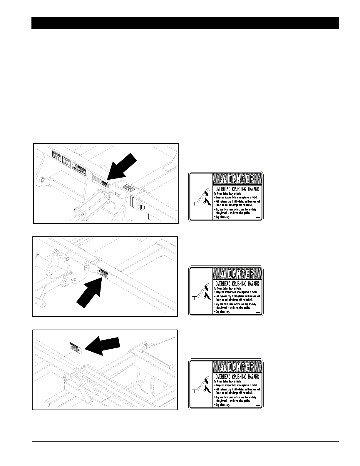
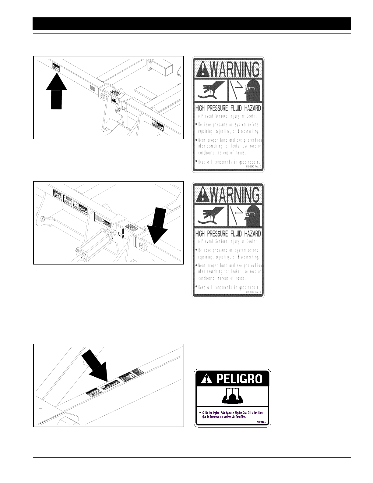
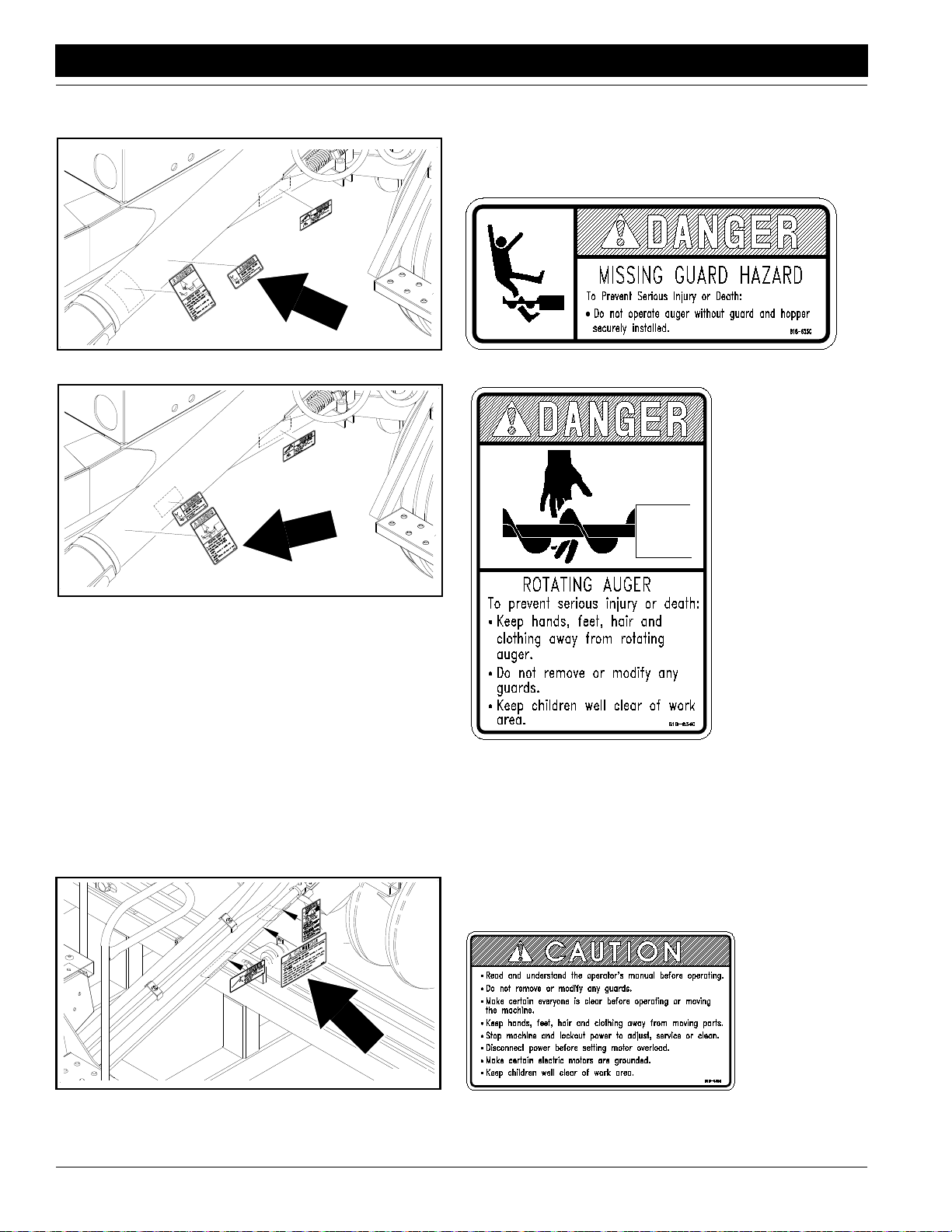
Safety Labels
Your implement comes equipped with all safety labels in place.
They were designed to help you safely operate your implement.
1. Read and follow label directions.
2. Keep all safety labels clean and legible.
3. Replace all damaged or missing labels.
4. Some new equipment installed during repair require safety
labels to be affixed to the replaced component as specified
14356
by the manufacturer. When ordering new components make
sure the correct safety labels are included in the request. To
order new labels go to your Great Plains dealer.
5. Refer to this section for proper label placement.
To install new labels:
a. Clean the area the label is to be placed.
b. Peel backing from label. Press firmly on surface
being careful not to cause air bubbles under label.
818-046C
Charge Fold Cylinder
14348
14349
7/28/10
818-046C
Charge Fold Cylinder
818-046C
Charge Fold Cylinder
Model 1150 1995 - 1997 167-058M
3
Page 6
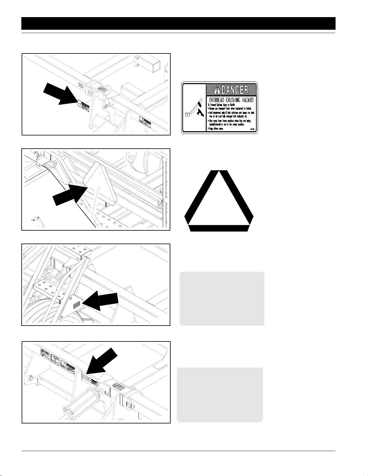
Important Safety Information
14350
Great Plains Mfg., Inc.
818-046C
Charge Fold Cylinder
14346
14777
818-055C
Slow Moving Vehicle Label
818-229C
Amber Reflector (2 places)
818-229C
14356
Model 1150 1995 - 1997 167-058M 7/28/10
4
Amber Reflector (2 places)
Page 7
Great Plains Mfg., Inc.
Important Safety Information
14811
14343
818-229C
Amber Reflector (2 places)
818-230C
Red Reflector (2 places)
7/28/10
14347
818-230C
Red Reflector (2 places)
Model 1150 1995 - 1997 167-058M
5
Page 8
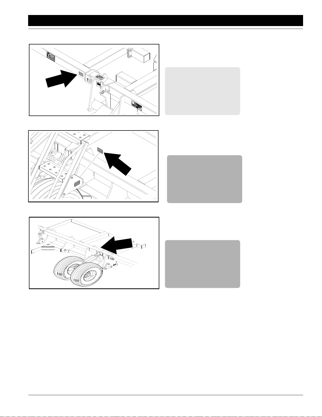
Important Safety Information
14340
Great Plains Mfg., Inc.
818-339C
High Pressure
14344
14352
818-339C
High Pressure
818-339C
High Pressure
Model 1150 1995 - 1997 167-058M 7/28/10
6
Page 9
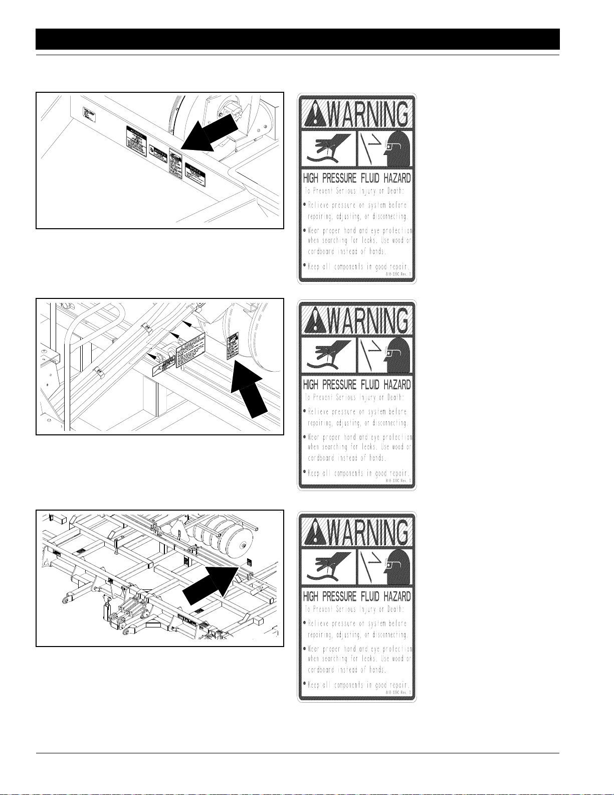
Great Plains Mfg., Inc.
Important Safety Information
14804
14356
818-339C
High Pressure
818-339C
High Pressure
7/28/10
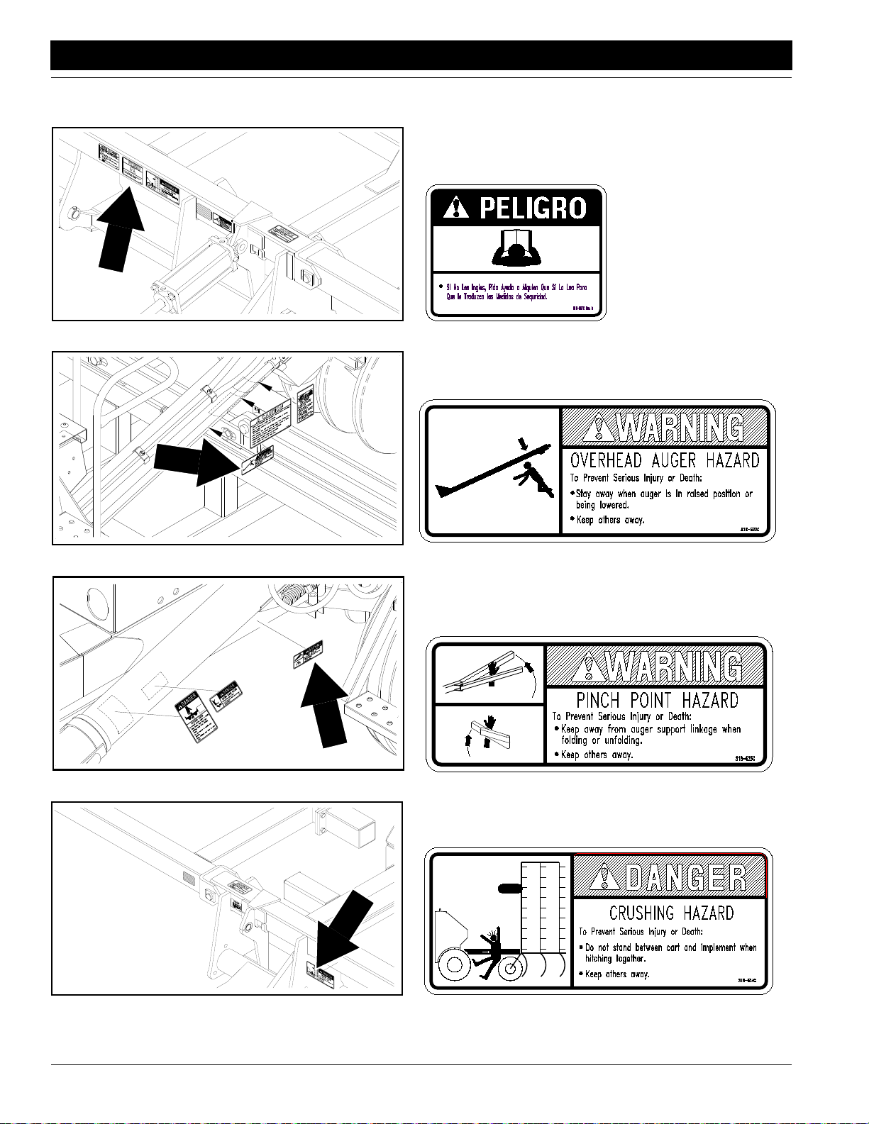
14339
818-557C
Cannot Read English
Model 1150 1995 - 1997 167-058M
7
Page 10
Important Safety Information
14356
Great Plains Mfg., Inc.
818-557C
Cannot Read English
818-622C
Overhead Auger
14806
818-623C
Pinch Point Auger
14342
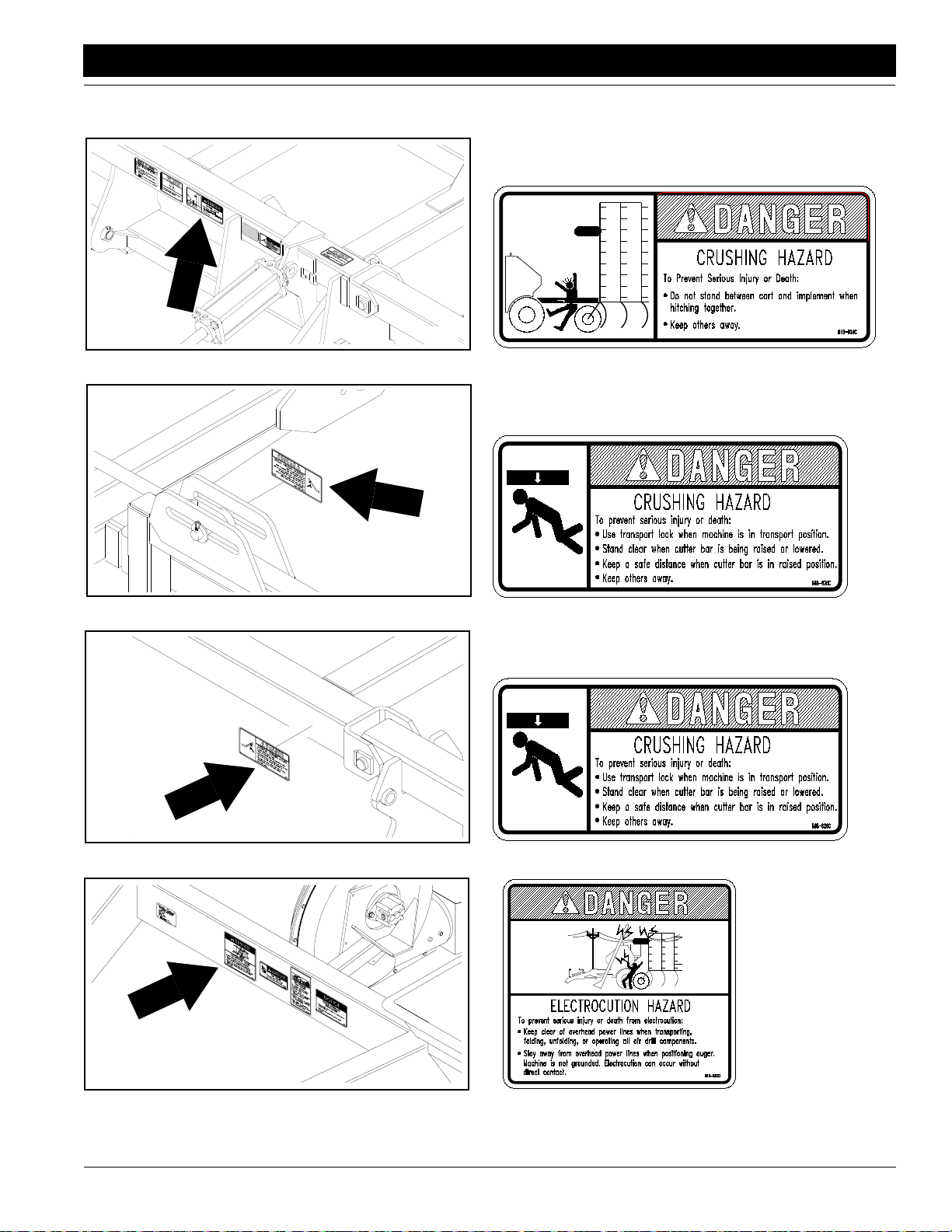
818-624C
Crush Ad/Implement
14805
Model 1150 1995 - 1997 167-058M 7/28/10
8
Page 11
Great Plains Mfg., Inc.
Important Safety Information
818-624C
Crush Ad/Implement
14356
818-626C
Overhead Crush Ad
14354
14355
818-626C
Overhead Crush Ad
14340
7/28/10
818-627C
Electrocution Auger
Model 1150 1995 - 1997 167-058M
9
Page 12

Important Safety Information
Great Plains Mfg., Inc.
14351
14808
818-627C
Electrocution Auger
818-627C
Electrocution Auger
818-628C
AD Bin Hazards
14345
Model 1150 1995 - 1997 167-058M 7/28/10
10
Page 13
Great Plains Mfg., Inc.
Important Safety Information
14339
14339
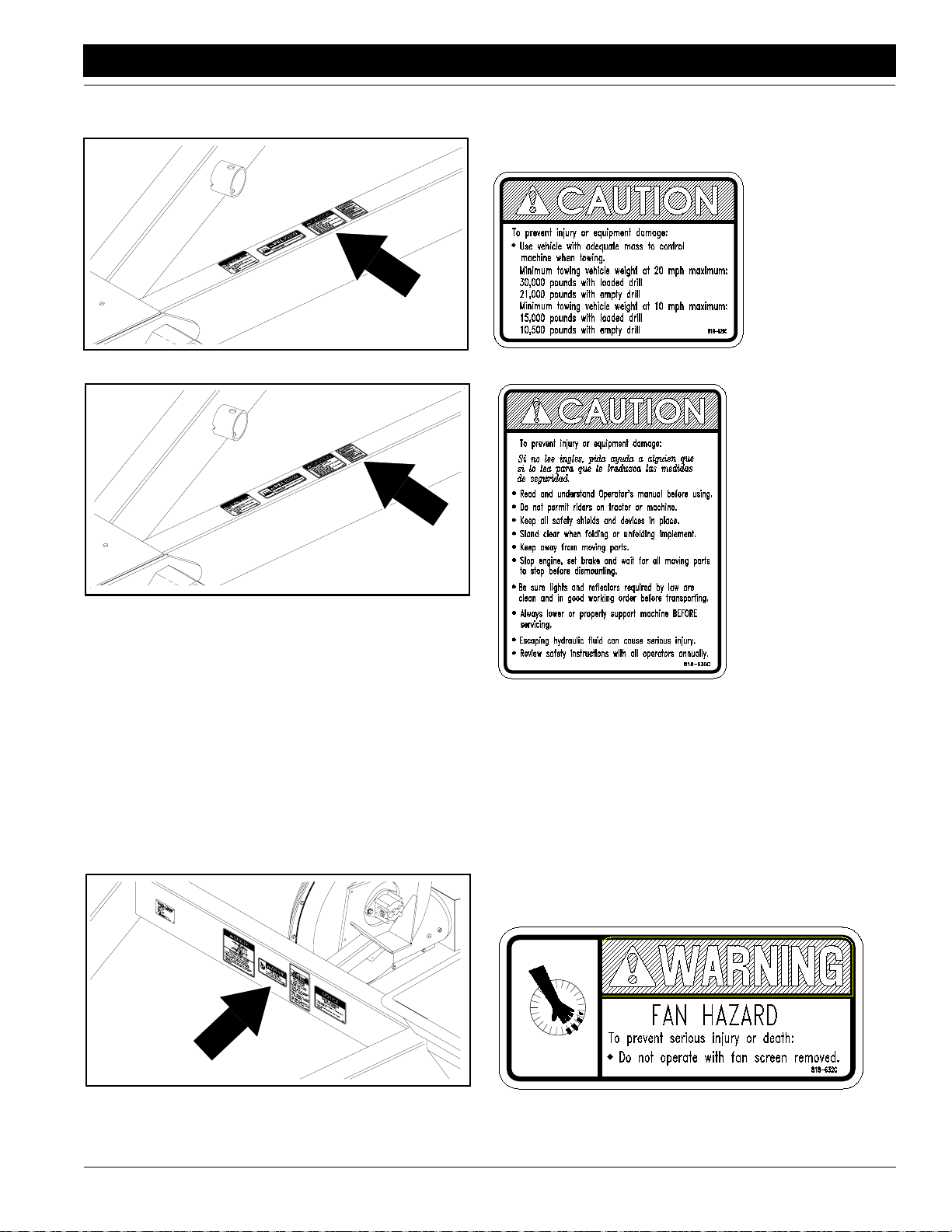
818-629C
AD Tow Vehicle
818-630C
AD General Instructions
14339
7/28/10
818-632C
AD Fan Hazard
Model 1150 1995 - 1997 167-058M
11
Page 14
Important Safety Information
Great Plains Mfg., Inc.
818-633C
Guard Missing Auger
14809
14810
818-634C
AD Rotating Auger
818-635C
14807
Model 1150 1995 - 1997 167-058M 7/28/10
12
AD Auger General
Page 15
Great Plains Mfg., Inc.
Introduction
Introduction
Great Plains welcomes you to the growing family of new
product owners. This implement has been designed with
care and built by skilled workers using quality materials.
Proper assembly, maintenance, and safe operating practices will help you get years of satisfactory use from the
machine.
Description of Unit
The 1150 Air Drill is a grain drill using air to move seed
from the metering device under the grain bin to the opener
units on the implement. The air is supplied by a hydraulic
motor driven fan. The seed is held in a pressurized bin and
is metered into the air stream in a pressurized meter. The
1150 Cart is designed to pull between the tractor and the
seeding implement andwill pull up to 45’ wide implements.
The metering device is driven at a rate proportional to
ground speed and the rate can be set using the gearbox
and other means.
Features include:
• Ladders to walkboard on both sides for easy access
• Electric clutch drive with adjustable heightcontrol switch
for automatic shut off on headlands
• Large bin opening with over-center lid latch
• Seed level sight glasses in multiple locations
• Easy open meter lids and hand drive crank for checking
seeding rate while stationary
• Bin has large angles on side slopes to provide complete
filling and emptying without hand stuffing.
• 150 bushel bin capacity
• Integral style hitch to implement prevents skewing on
hillsides and make backing up easy
• Three shank options and three opener options for imple-
ment
Intended Usage
This machine is intended to be used primarily for seeding
small grains and legumes in conventional tillage. It can
also be used in many reduced tillage applications and with
other crops.
assure you of the best performance.
Terminology:
"Right " or "Left" as used in this manual is determined by
facing the direction the machine will travel while in use unless otherwise stated.
Definitions:
NOTE: A special point of information related to it’s
preceding topic. The author’s intention is that you
read and note this information before continuing.
IMPORTANT: Information, related to it’s proceeding topic,
that the author feels would be of use.
Owner Assistance
If customer service or repair parts are required contact
your local Great Plains Dealer. He has trained personnel,
repair parts, and the equipment needed to service your
implement.
These parts have been specially designed and should
only be replaced with genuine Great Plains parts.
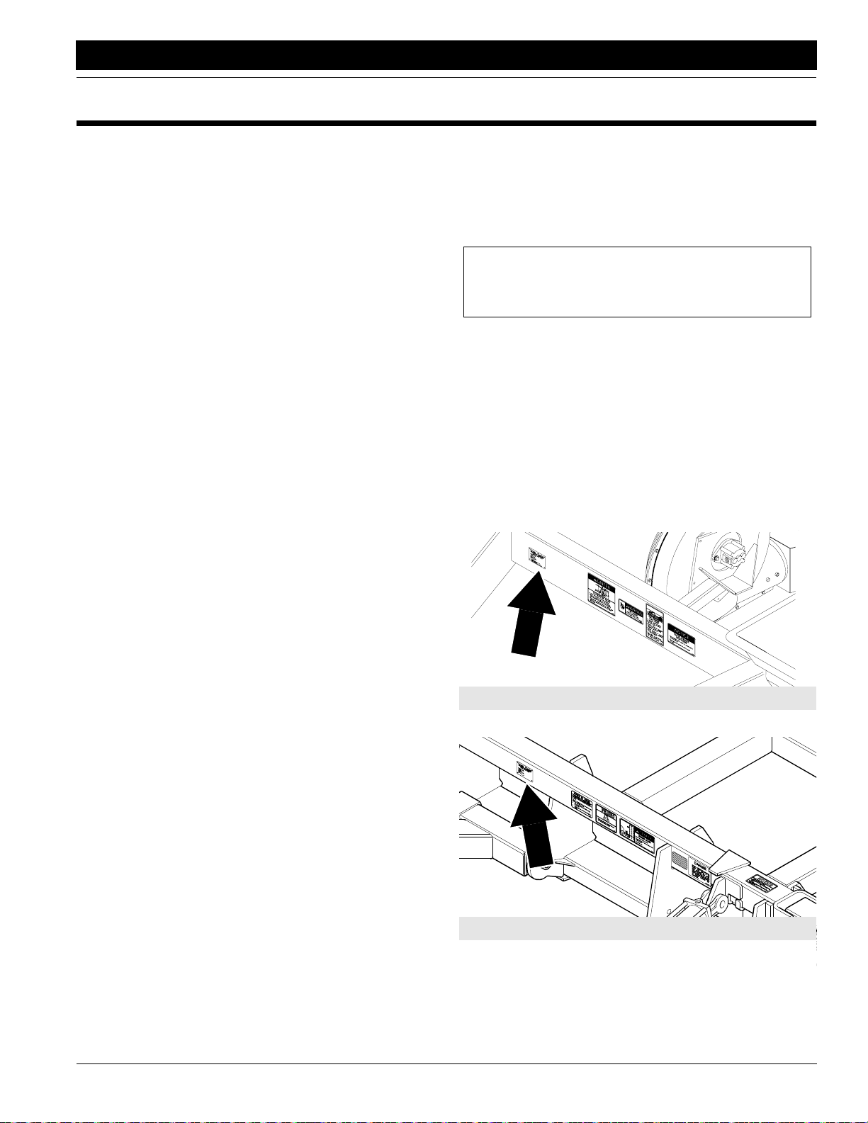
Serial Number Plate
Refer to Figure1 forthe location of your serial number plates.
14340
Air Drill Cart
Using This Manual
This Operator’s Section is designed to help familiarize you
with safety, assembly, operation, adjustments, troubleshooting, and maintenance. Read this manual and follow
the recommendations to help ensure safe and efficient
operation.
The warranty sheet should be filled out by the owner and
dealer at the time of purchase. After completion give the
dealer the white copy and send the pink copy to Great
Plains. Keep your copy in the manual for use when corresponding with the dealer.
To order a new Operator or Parts Manual contact your authorized dealer or write to the address listed below in the
Owner Assistance paragraph. Include the model and serial numbers of your unit.
The information contained within this manual was current
at the time of printing. Some parts may change slightly to
7/28/10
14595
Air Drill Implement
Serial Number Plate Locations
Figure 1
Model 1150 1995 - 1997 167-058M
13
Page 16

Introduction
Great Plains Mfg., Inc.
For prompt service always use theserial numberand model
number when ordering parts from your Great Plains Dealer.
Be sure to include your serial and model numbers in correspondence also.
Your dealer wants you to be satisfied with your new machine. If for any reason you do not understand any part of
this manual or are not satisfied with the service received,
the following actions are suggested:
1. Discuss the matter with your dealership Service Manager make sure he is aware of any problems you may
have and that he has had the opportunity to assist you.
2. If you are still not satisfied or do not understand any
part of this manual seek out the Owner or General
Manager of the dealership, explain the problem and
request assistance.
3. For further assistance write to:
Product Support
Great Plains Mfg. Inc., Service Department
P.O. Box 245
Assaria, Ks. 67416
Model 1150 1995 - 1997 167-058M 7/28/10
14
Page 17

Great Plains Mfg., Inc.
!
Section 1 Cart Assembly and Setup
Section 1 Cart Assembly and Setup
The following information is general in nature and was
written to aid the operator in preparing the tractor and drill
for use, and to provide general operating procedures. The
operator’s experience, familiarity with the machine, and
the following information combined should provide efficient drill operation and good working habits.
Having all the parts and equipment readily at hand will
speed your assembly task and make the job as safe as
possible.
Pre-Assembly Checklist
Check Reference
All major frame components Operator’s
Fasteners and pins that were shipped with
the drill.
NOTE: All hardware from the factory has
been installed in the location where it will
be used. If a part or fastener is temporarily
removed for assembly reasons, remember
where it goes. Keep the parts separated.
All working parts are moving freely, bolts
are tight and cotter pins are spread.
All grease fittings are in place and lubricated.
Proper tension and alignment on all drive
chains.
Safety labels are correctly located and legible. Replace if damaged.
Red and amber reflectors are correctly
located and visible when the drill is in the
transport position.
“Slow moving vehicle” emblem is in place. Important Safety
Inflate tires to specified air pressure. Tighten
wheel bolts to specified torque.
Have a minimum of 2 people at hand while
assembling the drill.
Have a fork lift or hoist along with chains
and safety stands that are sized for the job
ready for the assembly task.
Manual
Operator’s
Manual
Operator’s
Manual
Section 6
page 69
Operator’s
Manual
Important Safety
Information
Important Safety
Information
Information
Section 9
page 86
Operator’s
Manual
Operator’s
Manual
General Description
This section covers the dealer’s requirements to assemble
the drill.
Tools required
• Fork lift or overhead hoist with 6500# capacity.
• General hand tools
• Jack stands or blocks and safety chain
Shipping information
Your drill is shipped via flat bed truck.. The drill is not fully
assembled.
Unload all equipment before beginning assembly. Do not
attempt any assembly work while drill is on the truck.
Read and understand the previous section, “Important
Safety Information” page 1, before starting assembly.
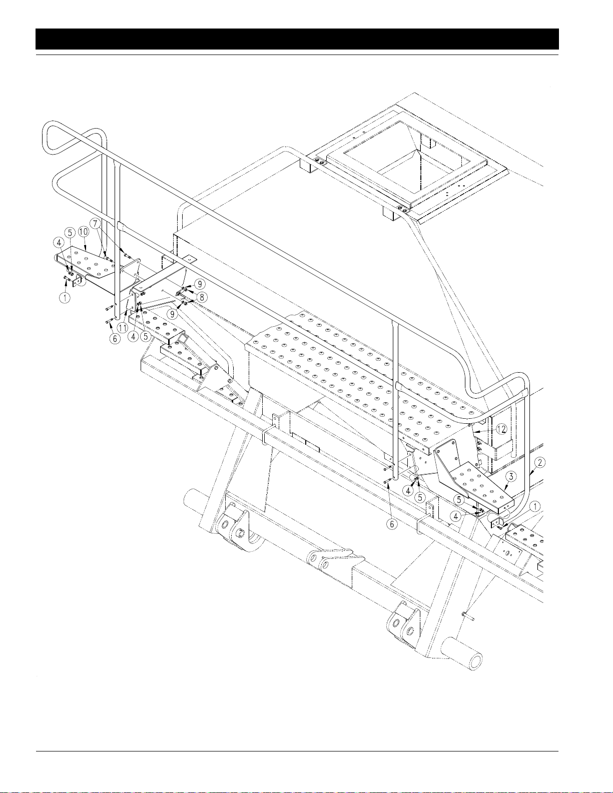
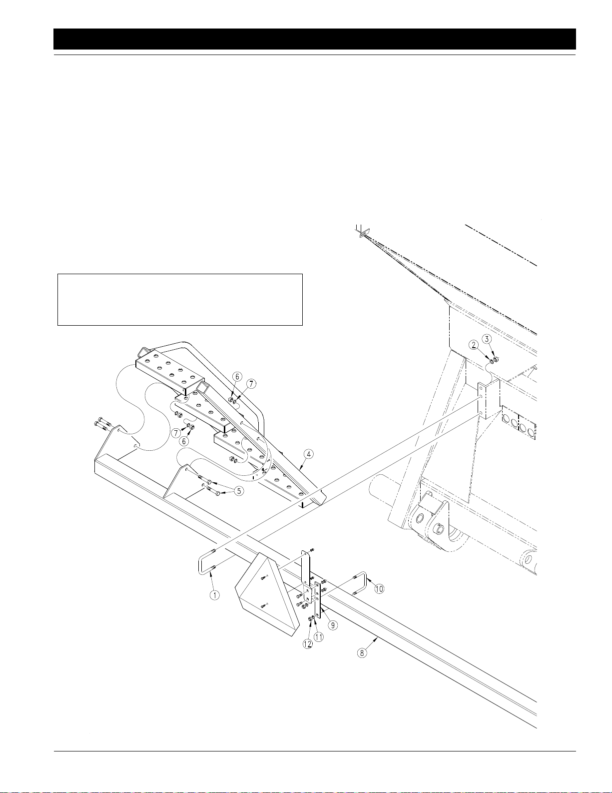
Top Steps & Rear Handrail
WARNING!
Do not climb on walkboard unless top ladder steps and handrails are securely installed.
Refer to Figure 1-1:
Working from the ground, attach the top step weldment,
left hand (#10), to the left side walkboard support (#11) using three 3/8” x 1” long bolts, (#7) 3/8” nuts (#8), and 3/8”
lockwashers (#9). Install the bolts so that the nuts are toward the center of the drill. Use the same method to attach
the top step weldment, right hand (#3), to the right side
walkboard support.
Use a fork lift or hoist to raise the rear handrail into position. Bolt the handrail (#2) to the rear of the left and right
walkboard supports (#11 & #12) using the 5/16” x 1 3/4”
long bolts (#6), 5/16” lockwasher (#4), and 5/16” nuts (#5).
Install the bolts so that the nuts are towards the front of the
drill. Do not over-tighten bolts, refer to the Torque Values
Chart in the “Appendix” section on page 86. Attach the
handrail end to the left and right ladder top steps (#3 &
#10) using the5/16” x 1” long bolts (#1), 5/16”lockwashers
(#4), and 5/16” nuts (#5). Install the bolts so that the nuts
are toward the center of the drill, refer to Figure 1-1.
7/28/10
Model 1150 1995 - 1997 167-058M
15
Page 18
Section 1 Cart Assembly and Setup
Great Plains Mfg., Inc.
14775
Top Step and Rear Handrail Installation
Figure 1-1
Model 1150 1995 - 1997 167-058M 7/28/10
16
Page 19
Great Plains Mfg., Inc.
!
Section 1 Cart Assembly and Setup
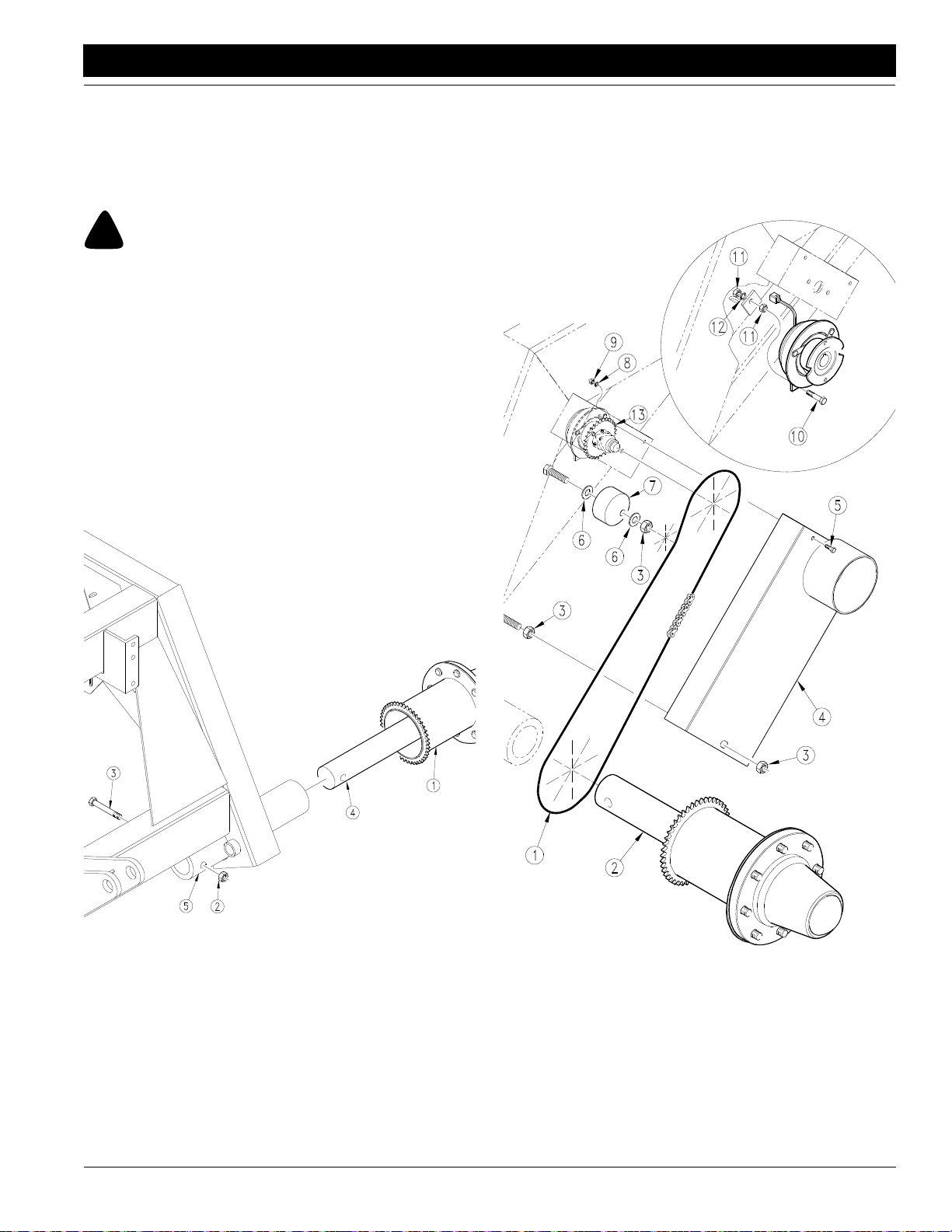
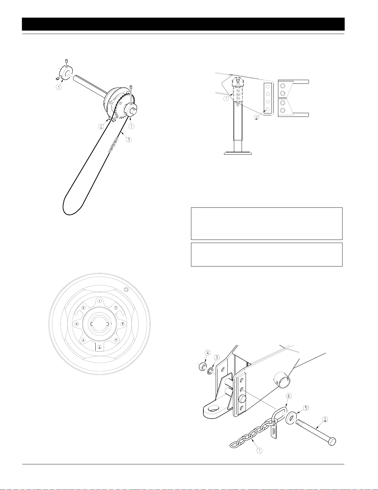
Spindles, Hubs, Wheels, & Drive Chain
Raise the rear of the cart off the ground high enough to let
the spindles slide into the tubes with hubs attached (the
spindle tube should be approximately 6” above the ground
at lowest point).
DANGER!
Crushing hazard. You may be severely injured or killed by the
drill if it falls. Always support the drill securely with jack stands
or blocks before working on unit raised off of the ground.
IMPORTANT: Put the hub and spindle assembly with the
drive sprocket on the right side of the drill. Install the assembly without the drive sprocket on the left side of the
drill.
Refer to Figure 1-2 to and line up the bolt hole (#4) in the
hub and spindle assembly with the bolt hole in the spindle
tube (#5). Slide the hub and spindle assembly (#1) into the
tube until the holes are aligned, refer to Figure 1-2. Secure
the hub and spindle assembly in the tube using the 3/4” x
5” long bolt (#3) and the 3/4” lock nut (#2).
implement and that a 29 tooth sprocket is used on the
clutch for the 45’ implement.
Install the main drive chain (#1) on the hub drive sprocket
(#2) and electric clutch sprocket (#16). The chain goes in
front of the drive chain tensioner (#9).
14459
Spindle Installation
Figure 1-2
Refer to Figure 1-3:
Remove the drive chain mud guard (#5). Loosen the nut
(#7) securing the drive chain tensioner (#9). Turn tensioner until the thinnest area is toward the front of the drill.
IMPORTANT: Before installing the drive chain make sure
that a 38 tooth sprocket is used on the clutch for the 34’
7/28/10
14436
Main Drive Chain Installation
Figure 1-3
Rotate the drive chain tensioner counterclockwise to remove excess chain slack then re-tighten nut (#7) to secure. Check alignment of the chain and sprockets. If
adjustment is needed, loosen the set collars (#1) holding
Model 1150 1995 - 1997 167-058M
17
Page 20
Section 1 Cart Assembly and Setup
Great Plains Mfg., Inc.
the electric clutch (#2) in place and slide the clutch over to
align chain, refer to Figure 1-4.
Drive Chain Alignment
Figure 1-4
14462
Re-tighten the set collars (#1) on both sides of the clutch
and re-tension chain. When the chain has been installed
and adjusted replace the drive chain mud guard. Raise the
rear of the cart until the center of the hubs are approximately 21” above the ground and securely block. Install
the tires and wheels on the hubs and tighten using recommended pattern, refer to Figure 1-5.
pin. With the drill on level ground adjust the jack until the
center of the frame and bin are level. There are three sets
of holes (#2) in the tongue, with the reversible hitch this
provides six different hitch heights, refer to Figure 1-6.
14439
Hitch Height Adjustment
Figure 1-6
Measure the height at the top of the drawbar on the tractor
that the drill is to be attached to. Install the hitch so that the
bottom of the strap is at the position closest to the height of
the tractor drawbar.
NOTE: When hitching the drill to a different tractor
check for a difference in the drawbar heights and readjust as needed.
NOTE: Make sure that the hitch is securely bolted to
the drill tongue.
14440
Pattern of Tire and Wheel Installation
Figure 1-5
Remove the blocks and lower the cart to the ground.
Check air pressure in tires and inflate to value listed in the
Tire Inflation Chart in the “Appendix” section starting on
page 86.
Hitch, Safety Chain, & Jack
Raise the tongue off the ground until the jack slides into
the jack stob (#1). Place the jack in the stob and securely
Refer to Figure 1-7:
Your drill comes equipped with a safety chain (#1). The
safety chain should be attached securely to the drill
tongue with a 1 1/4” x11” bolt (#2), 1 1/4” lock washer (#3),
and 1 1/4” nut (#4). The safety chain washer (#5) must be
installed outside of the safety chain attaching ring (#6).
The chain must always be securely fastened to a suitable
anchor on the towing vehicle before moving the drill.
Retract and unpin the jack. Store the jack horizontally in
the stob between the tongue rails when moving drill.
14568
Safety Chain
Figure 1-7
Model 1150 1995 - 1997 167-058M 7/28/10
18
Page 21
Great Plains Mfg., Inc.
Section 1 Cart Assembly and Setup
Lower Ladder Weldment
and Lower Ladder Support Weldment
Refer to Figure 1-8:
Install the lower ladder support weldment (#8) to the rear
of the cart with the 1/2”-13 x 3 1/32” x 4” u-bolts (#1), 1/2”
lock washers (#2), and 1/2” nuts (#3). Attach the lower ladder support so that the longest edge, along the mounting
plates, is on the bottom and that the mounting plates face
toward the front.
Be sure that the lower ladder support weldment is centered from side to side before tightening the u-bolts.
Install the left hand lower ladder weldment on the left side
of the drill using four 1/2” x 3” bolts (#5) with the 1/2” lockwashers (#7), and the 1/2” nuts (#6). Install the bolts so
that the nuts are toward the center of the ladder. Use this
procedure for installing the right side ladder.
NOTE: The lower ladders are identified left and right
by orienting them so that the handrails are located toward the outside of the drill, refer to Figure 1-8.
Slow Moving Vehicle
Bracket & Emblem
Bolt the slow moving vehicle (SMV)support bracket (#9) to
the center of the lower ladder support weldment (#8)
using one 3/8” x 3 1/32” x 4” u-bolt (#10), the 3/8” lock
washers (#11), and 3/8” nuts (#12). Install the bracket on
the rear edge of the tube with the remaining holes in the
bar on the top. Attach the SMV emblem and bracket to the
support using the supplied hardware. Install the SMV
bracket with the offset to the rear.
7/28/10
Lower Ladder Installation
Figure 1-8
14463
Model 1150 1995 - 1997 167-058M
19
Page 22
Section 2 Implement Assembly and Setup
!
!
Section 2 Implement Assembly and Setup
WARNING!
Obey all safety instructions from lifting equipment manufacturer.
Do not walk or place any part of the body under the raised sections. Be sure transport stands are securely attached prior to lifting. Be sure lifting equipment has enough capacity to lift sections.
NOTE: Each implement section in a stack can weigh
2100 pounds with 7” row spacing and spring reset
openers. Each 9 1/2’ wing section used on 34’ implements weighs approximately 2400 pounds.
1. Remove the implement sections from the truck and
place them on the ground.
2. With all stacks securely on the ground remove the ubolts from the bottom of the shipping stand on the
highest sections so that the stand remains attached to
the upper section.
3. Carefully lift the section off of the stack and place it on
solid, level ground or concrete if available.
4. Repeat steps 2 and 3 with each section, placing the
sections approximately in the position for assembly.
Great Plains Mfg., Inc.
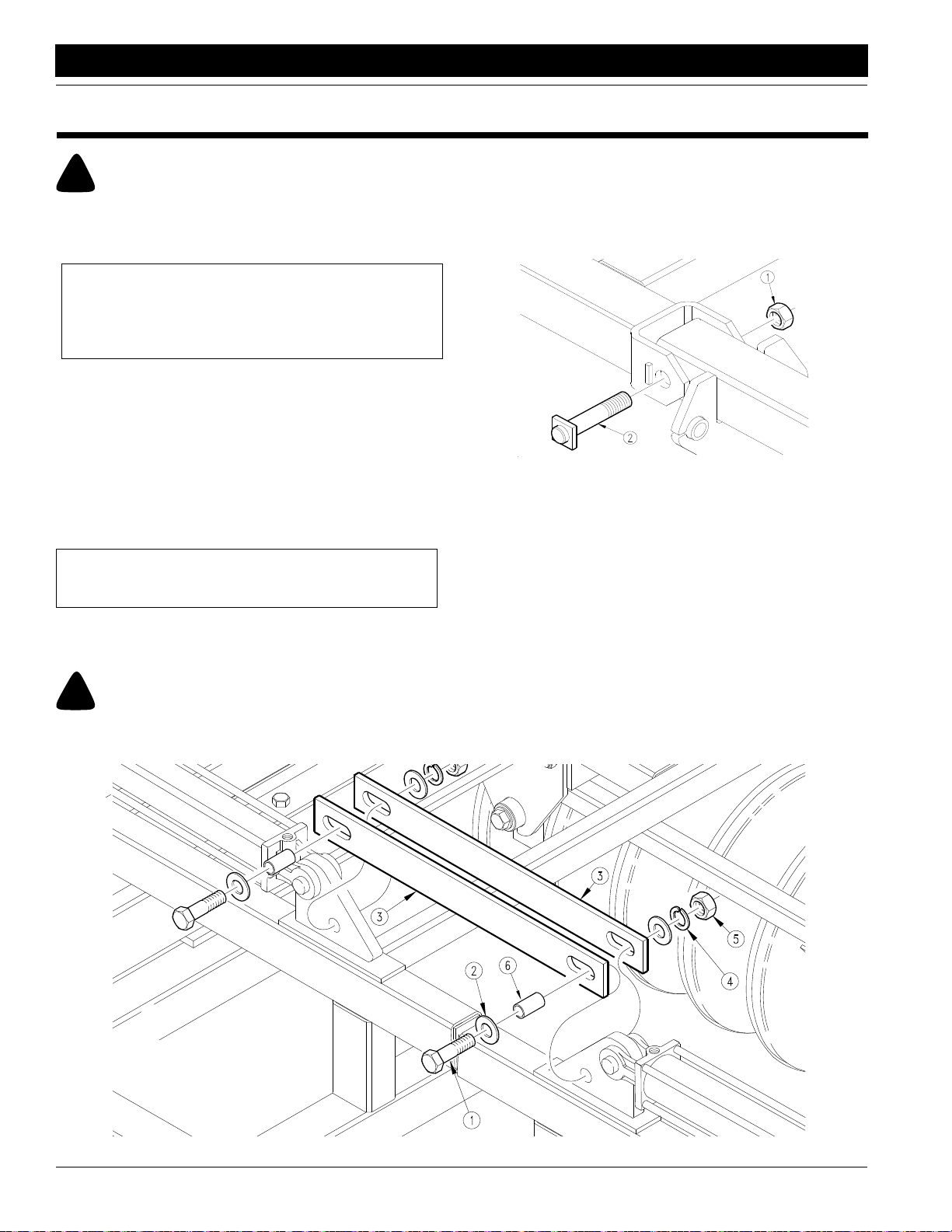
6. When the holes are aligned install the pivot clevis bolts
(#2) in place and secure them with 1” nylock nuts (#1).
When installing the bolts install so that the flat section
of bolt head is aligned with the square stock on the
clevis.This is to prevent the bolt from rotating in the
clevis, refer to Figure 2-1.
14441
Pivot Pin Installation
Figure 2-1
Repeat steps 5 and 6 until all sections are bolted
together.
NOTE: Be sure that the pivot bushings are in place in
the pivot tubes before positioning sections.
5. Use the hoist or forklift to position adjacent sections so
that the holes in the clevis line up with the holes in the
pivot tubes.
WARNING!
Do not place any part of the body between the frame sections
when aligning holes or severe injury may result.
Flex Limiter Bars
Refer to Figure 2-2:
1. Position the flex limiter bars so that the slots line up with
the holes in the lugs near the center of the implement.
2. Install the 7/8” x 3 1/2” bolts (#1), 7/8” flat washers
(#2), 7/8” flex limiter bar space tubes (#6), flex-limiter
bars (#3), 7/8” lock washer (#4), and 7/8” nut (#5) at
each end of tube. The flex limiter bars should be free
to move from side-to-side on the bolts.
Flex Limiter Bar Installation
Figure 2-2
14483
Model 1150 1995 - 1997 167-058M 7/28/10
20
Page 23

Great Plains Mfg., Inc.
Section 2 Implement Assembly and Setup
Implement Lift
Cylinder Hydraulic Hoses
NOTE: The SAE o-ring and JIC 37˚ flare type hose
connections do not require sealant for reconnecting.
They do not require high torque for a good seal.
Refer to Figure 2-3 and Figure 2-4. Install the hydraulic
hoses in place on the lift wheels. Note the hose lengths
listed and be sure to use the correct length of hose in each
location. Install the longest hose first and work down to the
shortest hose length.
The row openers in some locations have hose clips (#1)
mounted on them,refer to Figure2-5. Hydraulic hoses should
always be routed through the clips to prevent damage.
7/28/10
Model 1150 1995 - 1997 167-058M
21
Page 24
Section 2 Implement Assembly and Setup
34’ Lifting Hydraulics
Hydraulic Hose Sizes
Item Part Number I.D. Length
1 811-235C 3/8 222
Great Plains Mfg., Inc.
2 811-237C 3/8 174
3 811-245C 3/8 74
4 811-245C 3/8 74
5 811-236C 3/8 84
6 811-123C 3/8 51
7 811-237C 3/8 174
8 811-235C 3/8 222
9 811-127C 3/8 111
10 811-127C 3/8 111
34’ Lifting Hydraulics
Figure 2-3
Model 1150 1995 - 1997 167-058M 7/28/10
22
14464
Page 25
Great Plains Mfg., Inc.
Section 2 Implement Assembly and Setup
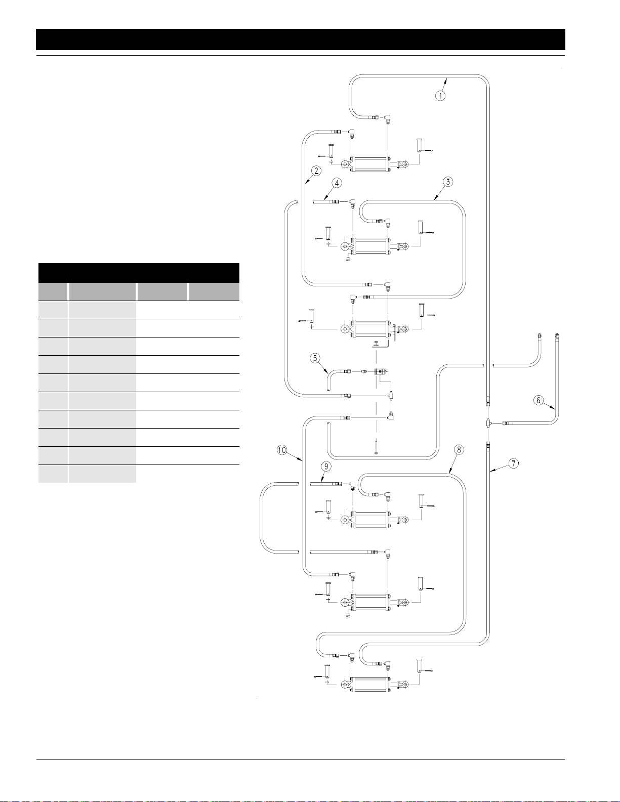
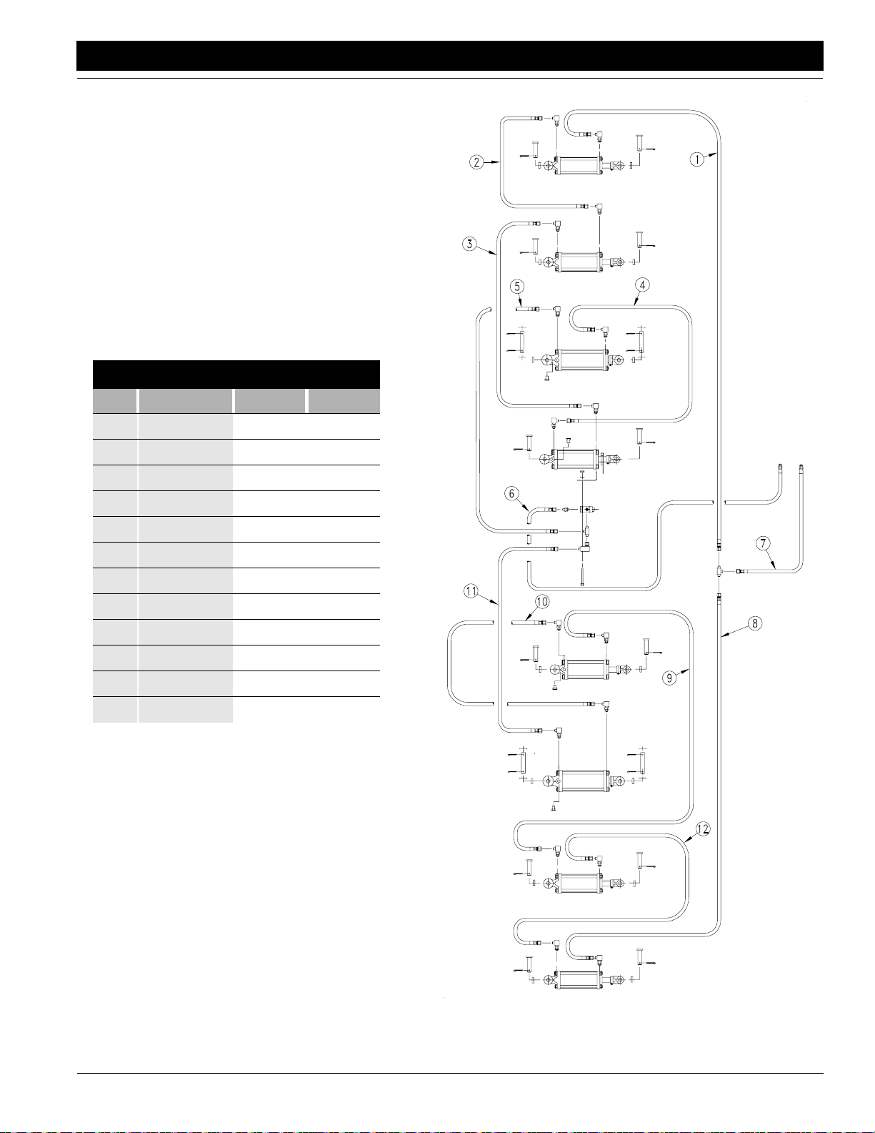
45’ Lifting Hydraulics
Hydraulic Hose Sizes
Item Part Number I.D. Length
1 811-124C 3/8 268
2 811-125C 3/8 82
3 811-310C 3/8 198
4 811-245C 3/8 74
5 811-245C 3/8 74
6 811-236C 3/8 84
7 811-123C 3/8 51
8 811-124C 3/8 268
9 811-311C 3/8 242
10 811-127C 3/8 111
11 811-127C 3/8 111
12 811-125C 3/8 82
7/28/10
45’ Lifting Hydraulics
Figure 2-4
Model 1150 1995 - 1997 167-058M
14465
23
Page 26
Section 2 Implement Assembly and Setup
!
Great Plains Mfg., Inc.
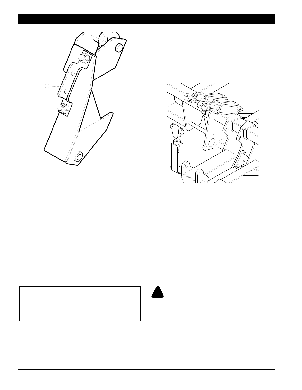
NOTE: The cylinders located directly behind the cart
will not pivot upward for bleeding, and must be unpinned at both ends and then supported with the rod
end port higher than the base end port. Refer to Figure 2-6.
port higher than the base end port.
14444
Hydraulic Hose Clips
Figure 2-5
IMPORTANT: When the lift cylinder hoses are installed
carefully check them to be sure they are not rubbing on
any sharp edges. Check that the hoses are loose enough
to allow the implement to fold or unfold and raise or lower
without damage. Be sure that hoses will not bind or get
pinched during operation. If hoses are in a position where
they might get damaged change their route until they are
safe.
Bleeding the Hydraulic Lifting System
The implement lifting system is equipped with rephasing
type hydraulic cylinders thatrequire a special procedure for
bleeding air from the hydraulic circuits. Read and follow the
procedure carefully. The rephasing type cylinders will not
function properly with air in the hydraulic circuit. This will
cause uneven seeding depth across the implement.
NOTE: Check the hydraulic fluid in the tractor reservoir and fill to the proper level. Add fluid to the system
as needed. A low reservoir level may draw air back
into the system, causing jerky or uneven cylinder
movement.
1. Jack up and support the front member of each implement frame section at a point close to each gauge
wheel.
2. With the frame blocked and supported, unpin the rod
end of the gauge wheel cylinders. Pivot the cylinders
up and wire; or otherwise safely support the rod end
14447
Center Hydraulic Cylinders
Figure 2-6
3. With the tractor engine at an idle speed, hold the remote lever on to put fluid into the lifting circuit. When
the outboard cylinders on both sides of the implement
have completely extended, hold the remote lever on
for one minute.
4. Retract the cylinder rods. Extend the rods again and
hold the remote lever on for one more minute. Repeat
this step two more times to completely bleed the system. If the gauge wheel leveling adjustments are to be
made, leave the cylinders unpinned and the implement frame supported.
5. Recheck the tractor reservoir and fill to the proper level.
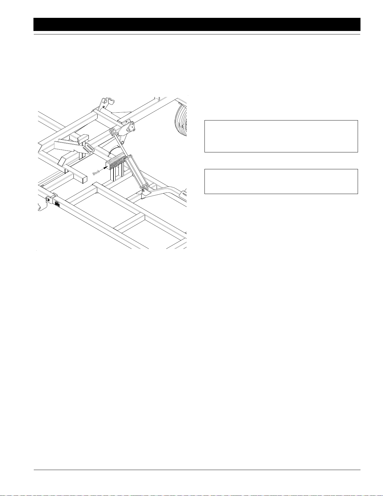
Fold Cylinders
DANGER!
The folding cylinders must be bled free of air before attempting
to fold implement, otherwise severe damage and bodily injury
may result. Refer to Figure 2-7:
34’ and 45’ Drills
Position main foldcylinders with base end toward center of
the drill, rod end toward wings. Pin the base end to the fold
cylinder lug. Secure the pin with the provided clip, refer to
Figure 2-7. Leave rod end unhooked and block up in the
air so that the rod will not come in contact with anything
when extended. Do not connect rod end until after air is
bled from fold circuit.
Model 1150 1995 - 1997 167-058M 7/28/10
24
Page 27
Great Plains Mfg., Inc.
Section 2 Implement Assembly and Setup
45’ Drills
Position the outer fold cylinders with the base end toward
the center of dill and rod ends out. Pin the base end to the
cylinder lug and secure with clip. Leave rod end unhooked
and block up so that the rod will not come in contact with
anything when extended. Do not connect the rod end until
after air is bled from the fold circuit.
Refer to Figure 2-8 and Figure 2-9. Install hydraulic hoses.
Note the hose lengths and be sure to use the correct length
hose in each location. Start with the longest hose and work
to the shortest.
Be sure to use the hydraulic hose clips on the openers and
route the hoses through them. When the hoses are
hooked up be sure that they are not twisted and will not get
pinched when the implement is raised, lowered, folded or
unfolded. Do not let the hoses rub on sharp edges and be
sure there is enough slack for down-flex.
NOTE: The SAE o-ring and JIC 37˚ flare type hose
connections do not require sealant for reconnecting.
They do not require high torque for a good seal.
NOTE: Do not try to fold the implement unless the flex
limiter bars are installed.
14446
Bleeding Fold Cylinders
Figure 2-7
7/28/10
Model 1150 1995 - 1997 167-058M
25
Page 28

Section 2 Implement Assembly and Setup
Great Plains Mfg., Inc.
45’ Folding Hydraulics
Hydraulic Hose Sizes
Item Part Number I.D. Length
1 811-095C 3/8 158
2 811-095C 3/8 158
3 811-118C 3/8 41
4 811-094C 3/8 176
5 811-094C 3/8 176
6 811-118C 3/8 41
7 811-096C 3/8 108
8 811-096C 3/8 108
9 811-117C 3/8 90
10 811-116C 3/8 66
45’ Folding Hydraulics
Figure 2-8
14478
Model 1150 1995 - 1997 167-058M 7/28/10
26
Page 29

Great Plains Mfg., Inc.
Section 2 Implement Assembly and Setup
7/28/10
34’ Folding Hydraulics
Figure 2-9
14479
34’ Folding Hydraulics
Hydraulic Hose Sizes
Item Part Number I.D. Length
1 811-240C 3/8 75
2 811-240C 3/8 75
3 811-241C 3/8 21
4 811-241C 3/8 21
5 811-239C 3/8 75
6 811-239C 3/8 75
Model 1150 1995 - 1997 167-058M
27
Page 30

Section 2 Implement Assembly and Setup
!
Bleeding the Folding System
NOTE: Check the hydraulic fluid in the tractor reservoir and fill to the proper level. Add fluid to the system
as needed. A low reservoir level may draw air back
into the system, causing jerky or uneven cylinder
movement.
1. Unpin the rod end of the fold cylinders and block up.
Wire or otherwise safely support the cylinders so
when the rod end is fully extended it does not contact
anything.
2. Cycle the cylinders completely in and out a minimum
of three times to purge the air from the fold system.
NOTE: On the 45‘ model if one side is completely in or
out and the other side is not moving release the tractor
hydraulic lever momentarily, reverse it and try again.
3. Fully extend the cylinders to repin the rod ends.
CAUTION!
Do not fold implement unless gauge wheel transport locks are
installed.
4. Recheck the tractor reservoir and fill to the proper level.
Side-to Side Frame Leveling
Equal seeding depth across the drill can only be maintained if all frames are level. Leveling adjustments should
be done during the initial setup of the drill. Periodic frame
leveling should not be necessary, however, you may field
check the level by laying a straight edge across at least
two frame members and out over a gauge wheel of that
frame. Measure the distance from the bottom of the
straight edge to the top of the gauge wheel tire. Compare
this measurement at the other gauge wheel tires, step 4. If
leveling is necessary follow the instructions listed.
45’ Drill Frame Leveling
1. The gauge wheel hydraulic circuit should be bled of air
and full of oil, see Bleeding the Hydraulic Lifting Sys-
tem, this section, on page 24.
2. Hydraulically lower the entire implement frame. The
frame should then be jacked up and supported, see
Bleeding the Hydraulic Lifting System, this section, on
page 24, and implement sections one and six noncastored gauge wheel cylinders should be unpinned
at the rod end and safely supported.
3. Retract all gauge wheel cylinders fully. Since the dual
gauge wheels on the implement sections three and four
are non-adjustable all adjustments will be made with
these as a reference. A reference measurement must
be taken from the top of the implement frame to the center of one dual gauge wheel axle, refer to Figure 2-10.
Great Plains Mfg., Inc.
14575
Dual Gauge Wheel Arm
Figure 2-10
4. With all cylinders fully retracted lay a straight edge
across at least two frame members of either implement section three or four and extend the straight
edge out over the dual gauge wheel axle of that implement section. Measure the distance from the bottom
of the straight edge to the center of the dual gauge
wheel axle, approximately 11 5/8”.
Implement sections one and six non-castored gauge
wheels (inboard) should center on the measurement
determined above. Implement sections one and six
(outboard) gauge wheels should measure approximately 1/2” higher (subtract 1/2” from your measurement) because they carry less weight.
5. Lay a straight edge across the top of at least two frame
members of implement section one and out over the
non-castored gauge wheel axle. Raise the unpinned
gauge wheel and arm assembly up to where the center of the gauge wheel axle is at the measurement determined in step 4 above. Support the gauge wheel at
that point. Swing the cylinder down to the gauge
wheel arm and adjust the eye-bolt (#1), Figure 2-11,
until the pin holes line up. Secure the eye-bolt with the
jam nut and repin the cylinder to the gauge wheel arm.
Eye-bolt Adjustment
Figure 2-11
14448
Model 1150 1995 - 1997 167-058M 7/28/10
28
Page 31

Great Plains Mfg., Inc.
Section 2 Implement Assembly and Setup
6. Now move the straight edge so it lies over the castored gauge wheel axle. Adjust the eye-bolt at the
base end of the cylinder until the center of the axle is
approximately 1/2” higher (subtract 1/2” from your
measurement) than the measurement determined in
step 4. Secure eye-bolt by tightening the jam nuts.
7. Repeat steps 5 and 6 for implement section six.
8. Make sure that all cylinders are securely pinned.
9. The center of the implement is held by the cart sling.
This should be adjusted so the center of the machine
is level during field operation., refer to Figure 2-12.
10. For front-to-back leveling of the implement frame see
Cart Sling
Figure 2-12
14432
NOTE: Towers must be located so that there is no interference when wings are folded or unfolded. When
towers have been installed very slowly fold implement
while watching to be sure there is no interference. Do
not stand under a wing while it is being folded or unfolded! If towers have any interference lower wing then
move them slightly until they clear. Check clearance
before installing hoses.
5. Implement sections one and fourgauge wheels should
center on the measurement determined above. Lay a
straight edge across the top of at least two frame members of implement section one and out over the noncastored gauge wheel axle. Raise the unpinned gauge
wheel and arm assembly up to where the center of the
gauge wheel axle is at the measurement determined in
step 4 above. Support the gauge wheel at that point.
Swing the cylinder down to the gauge wheel arm and
adjust the eye-bolt (#1), refer to Figure 2-11, until the
pin holes line up. Secure the eye-bolt with the jam nut
and repin the cylinder onto the gauge wheel arm.
6. Repeat step 5 for implement section four.
7. Make sure that all cylinders are securely pinned.
8. The center of the implement is held by the cart sling,
refer to Figure 2-12. This should be adjusted so the
center of the machine is level during field operation.
9. For front-to-back leveling of the implement frame see
Setting the Seeding Depth and Leveling Front-to-Rear
under “Adjustments” on page 60.
Distribution Towers and Hoses
Setting the Seeding Depth and Leveling Front-to-Rear
under “Adjustments” on page 60.
34’ Drill Frame Leveling
1. The gauge wheel hydraulic circuit should be bled of air
and full of oil, see Bleeding the Hydraulic Lifting Sys-
tem, this section, on page 24.
2. Hydraulically lower the entire implement frame. The
frame should then be jacked up and supported, see
Bleeding the Hydraulic Lifting System, this section, on
page 24, and implement sections one and six noncastored gauge wheel cylinders should be unpinned
at the rod end and safely supported.
3. Retract all gauge wheel cylinders fully. Since the dual
gauge wheels on implement sections two and three
are non-adjustable all adjustments will be made with
these as a reference. A reference measurement must
be taken from the top of the implement frame to the
center of one dual gauge wheel axle.
4. With all cylinders fully retracted lay a straight edge
across at least two frame members of either implement
section two or three and extend the straight edge out
over the dual gauge wheel axle of that implement section. Measure the distance from the bottom of the
straight edge to the center of the dual gauge wheel axle, approximately 11 5/8”, refer to Figure 2-10.
NOTE: For best results distribution towers should be
mounted as vertically as possible. Installing towers
so that they lean strongly to one side may cause uneven distribution, especially on hillsides.
Refer to Figure 2-14 for tower mounting locations.
1. Install a tower support bracket at each location using
the 1/2” u-bolt (#1), 1/2” lock washers (#2), and 1/2”
nuts (#3), refer to Figure 2-13.
14546
Mounting Tower Brackets
Figure 2-13
7/28/10
Model 1150 1995 - 1997 167-058M
29
Page 32

Section 2 Implement Assembly and Setup
Great Plains Mfg., Inc.
34’ Drill
45’ Drill
Tower Mounting Locations
Figure 2-14
Model 1150 1995 - 1997 167-058M 7/28/10
30
14486
Page 33

Great Plains Mfg., Inc.
Section 2 Implement Assembly and Setup
2. Position a tower on bracket and secure with 2 u-bolts.
The bottom of lower round plate should be approximately 31 1/2 inches above the frame rails. Tower
should be turned so that inlet tube is pointed toward
the center of the drill. The center tower inlet should
face the front, refer to Figure 2-15.
These 2 hoses should also be the same length, (longer than the others.)
7. Secure all hoses to the frame using 24” cable ties being sure hose will not be damaged during drill operation.
1” Secondary Hoses
NOTE: Seed hoses must be routed to prevent them
from rubbing on sharp edges or being damaged
when the implement is raised, lowered, folded, or unfolded. Hoses must be pushed fully into distribution
tower ports until they contact their stop.
With the implement width and row spacing in mind refer to
the appropriate hose routing illustration for the correct assembly of hoses.
1. Loosen bolts holding tower halves together, refer to
Figure 2-16.
Do not remove bolts.
14499
Inlet Tube Alignment
Figure 2-15
Primary 2 1/2” Distribution Hoses
1. Start with center tower #3. Route hose as shown in
Figure 2-17. Slide hose at least two inches onto tower
inlet. (Slide clamp over the end first)
2. Allow enough hose so that implement raising, lowering, folding and unfolding will not pinch or bind hose.
3. Using a hacksaw cut hose so that it will slide onto
meter outlets up to end of flare.
4. Slide clamp over hose end then slide hose onto meter
outlet. Install clamp so that it will not interfere with other hoses, clamps, or meter door latch handles.
5. Repeat this procedure on towers #2 and #4. Cut these
two the same length but longer than the center hose.
6. Repeat the same procedures for towers #1 and #5.
Tower Assembly
Figure 2-16
14449
7/28/10
Model 1150 1995 - 1997 167-058M
31
Page 34

Section 2 Implement Assembly and Setup
Great Plains Mfg., Inc.
34’ Drill 7” Row Spacing
34’ Drill 10” Row Spacing
14542
14533
Seed Hose Routings
Figure 2-17
Model 1150 1995 - 1997 167-058M 7/28/10
32
Page 35

Great Plains Mfg., Inc.
Section 2 Implement Assembly and Setup
34’ Drill 12” Row Spacing
14534
7/28/10
45’ Drill 7” Row Spacing
Seed Hose Routings (con’t.)
Figure 2-17
Model 1150 1995 - 1997 167-058M
14543
33
Page 36

Section 2 Implement Assembly and Setup
45’ Drill 10” Row Spacing
Great Plains Mfg., Inc.
14535
45’ Drill 12” Row Spacing
14536
Seed Hose Routings (con’t.)
Figure 2-17
Model 1150 1995 - 1997 167-058M 7/28/10
34
Page 37

Great Plains Mfg., Inc.
Section 2 Implement Assembly and Setup
Refer to Figure 2-18:
2. Attach the end of the hose to opener.
For floating hoe openers slide clamp over the end of
the hose 6”. Put the end of the hose in the seed tube
6”. Hook the clamp ends in the holes at the top of the
seed tube.
3. Route the hose to the tower outlet. Allow just enough
slack for down flex of wings. Be sure to use outlet as
shown on routing diagram.
4. Allow 2 1/4” of the hose to extend past the edge of the
tower then squarely and smoothly cut off the hose.
5. Push the end of the hose into the port until it contacts
the ridge and stops, this is approximately 2 1/4”.
6. Repeat steps 1 through 6 for all 1” hoses on each tower.
7. When all hoses are installed on a tower, tighten the
bolts holding the halves together.
NOTE: The tower bolts are equipped with nylock nuts
and should not be over-tightened. Tighten the bolts
only until the hose is held securely against being
blown out. Do not bend tower plates.
8. Check all hosesto be sure that they are not rubbing on
sharp edges and will not be damaged when the drill is
raised, lowered, folded, or unfolded. Re-route if needed to prevent damage.
7/28/10
Hose Installation On Openers
Figure 2-18
14563
Model 1150 1995 - 1997 167-058M
35
Page 38

Section 2 Implement Assembly and Setup
Great Plains Mfg., Inc.
Light Harness and Brackets
Refer to Figure 2-19:
Attach the left (#11) and right (#3) side light brackets to the
left and right center sections of the implement. Use the
5/8”-11 x 2 3/4” bolts (#6) to secure them to the outer lift
assist pivot bearings. Install the left (#2) and right (#9) ag
lights on the brackets using the 1/4” x 1 1/4” bolts (#10),
lockwashers (#7), and nuts (#8). The lights should be installed with the red lenses to the inside and facing the rear.
Attach the light harness “Y” connector (#4) to the terminal
.
at the back of the cart (#1). Route the wires along the
frame members back to the lights and plug in.
NOTE: The lead with the green wire goes to the right
side lights, the lead with the yellow wire goes to the
left side when facing forward.
Secure the wire in place using the cable ties (#5). Coil the
excess wire and tie it securely to the implement frame
Safety Light Kit Installation
Figure 2-19
Model 1150 1995 - 1997 167-058M 7/28/10
36
14573
Page 39

Great Plains Mfg., Inc.
!
!
Section 3 Operating Instructions
Section 3 Operating Instructions
General Description
The seed metering mechanism of this drill is powered by
the cart tire and is driven at a rate proportional to distance
driven. This ensures that the rate applied in pounds per
acre remains constant as ground speed is varied. The
pounds per acre rate is adjustable and can be set using
the gearbox, speed change sprocket and hi-low gears on
the meter. The metering device is driven through an electro-magnetic clutch which will not engage unless the fan
motor is running at high speed and the implement is lowered past an adjustable height switch. This prevents the
primary seed hoses from being plugged by seed being
metered into them without the fan running and also allows
the seed to be shut off automatically when the drill is lifted
on head lands. The seed bin is sealed and held at the
same pressure as the meter chamber so that metering is
controlled mechanically and not by air flow fluctuations.
The metered seed is carried by air through the 5 primary
hoses to the distribution towers on the implement. These
towers then divide the air and seed into individual rows
and it is carried to the openers in the secondary hoses.
Prestart Checklist
• Lubricate the drill as indicated in the Lubrication portion
of the “Maintenance and Lubrication” section starting
on page 69.
• Check the tires for proper inflation, see the Tire Inflation
Chart in the “Appendix” section starting on page 86.
• Check the chains for proper tension and alignment as
shown in the Lubrication portion of the “Maintenance
and Lubrication” section starting on page 69.
• Perform all beginning of season and daily service items
discussed in the “Maintenance and Lubrication” section starting on page 69.
• Check the drill for worn or damaged parts and repair or
replace them before going to the field.
• All nuts, bolts and screws should be checked. Refer to
the Torque Value Chart in the “Appendix” section starting on page 86.
Attaching the Drill to the Tractor
NOTE: The tractor must be of adequate size to pull
the drill. When determining size of tractor keep in
mind the soil, terrain and row spacing.
NOTE: The tractor, or towing vehicle, must have adequate mass to control the drill when towing. Do not
exceed 20 miles per hour.
Minimum vehicle weight - loaded drill:
up to 20 mph maximum - 30,000 lbs.
up to 10 mph maximum - 15,000 lbs.
Minimum vehicle weight - empty drill:
up to 20 mph maximum - 21,000 lbs.
up to 10 mph maximum - 10,500 lbs.
DANGER!
You may be severely injured or killed by being crushed between
the tractor and the drill. Do not stand or place any part of your
body between the tractor and drill while hooking up the drill.
Back the tractor drawbar up to the drill until the holes in the
drill tongue and the tractor drawbar are in line. Use the
jack to make the height adjustments. Be sure that the hitch
is properly adjusted for level operation, refer to Hitch,
Safety Chain, and Jack in the “Cart Assembly and Set-
up” section on page 15. Install the drawbar pin and the pin
retainer clip. Remove the jack and store on the stob between the tongue side rails in horizontal position. Attach
the safety chain on the drill to an anchor on the tractor capable of pulling the unit.
NOTE: The tractor must have at least 3 sets of hydraulic outlets and be capable of supplying 15-30 gallons per minute at 2000 psi.
WARNING!
Escaping fluid under pressure can have sufficient pressure to
penetrate the skin. Check all hydraulic lines and fittings before
applying pressure. Fluid escaping from a very small hole can be
almost invisible. Use paper or cardboard, not body parts, and
wear heavy gloves to check for suspected leaks. If injured, seek
medical assistance from a doctor that is familiar with this type
of injury. Foreign fluids in the tissue must be surgically removed
within a few hours or gangrene will result.
Recommended Minimum Tractor Size
34’ Implement - 180 HP
45’ Implement - 240 HP
7/28/10
NOTE: The SAE o-ring and JIC 37˚ flare type hose
connections do not require sealant for reconnecting.
They do not require high torque for a good seal.
IMPORTANT: when using sealant on pipe threads the friction between the threads is reduced; therefore, be certain
not to overtighten or damage to the components may occur.
Model 1150 1995 - 1997 167-058M
37
Page 40

Section 3 Operating Instructions
!
When drawbar pin and safety chain have been installed
and jack has been removed the hydraulic hoses may be
connected. See your Great Plains dealer if you require
new quick coupler ends for your hoses.
Make sure that each pair of hoses connected to your tractor outlets are from the same circuit (lift, fold, or fan)
Hook up the electric clutch cable to the clutch harness on
the tractor.
If the tractor does not have a clutch harness installed it
must be installed now. Attach the switch box solidly to the
tractor in a convenient location not exposed to rain. Attach
the power leads to a 12 volt D.C. power supply, polarity is
not critical. Be sure that the wire is safely routed where it
will not be pinched or rubbed through. Before drilling any
holes always check on the back side to make sure no hidden components will be damaged by the drill.
Great Plains Mfg., Inc.
14452
Cart Link Attachment
Figure 3-1
Safety Lights
The light package your drill comes equipped with requires
that your tractor be wired for the standard 7-pin electrical
connector which will work with the tractor’s flashers and
signals. All that should be necessary is to plug in the connector.
If your tractor is not equipped with this connector please
consult your dealer for installation to tractormanufacturers
specifications.
Attaching 1150 Air Drill Cart to
Great Plains 34’ or 45’ Implement
DANGER!
You may be severely injured or killed by being crushed between
the tractor and the drill. Do not stand or place any part of your
body between the cart and implement while hooking up the drill.
Block the implement cart links (#1) so that the center of the
pin hole is approximately 22 3/4” above ground. If the cart
sling is present, pull it back towards implement to keep it
out of the way until ready to attach. Pull all seed and hydraulic hoses back away from the implement hitch to prevent damage. Line the cart up squarely in front of the
center of the implement. Back the cart up until both of the
cart links are between the hitch plates on the cart frame
and the pin holes are aligned. Re-adjust the height of links
by changing the blocks if required. When the holes are
aligned place the cart link pin (#2) in position, secure the
cart link pin with the 5/16” dia. lynch pins (#3). Be sure that
the tab on the link pin securely engages the square hole in
the hitch plate, refer to Figure 3-1.
Refer to Figure 3-2:
Make sure that the cart sling is connected to the pin on the
cylinder lift arm then align the top hole with the hole in the
cart sling support plates on the back of the cart frame. Install the cart sling pin (#2) and secure it with the 1/4” x 2”
cotter pins (#1). Be sure that the legs on the cotter pins are
spread apart.
Attach the 2 1/2” primary hosesfrom implement distributor
towers to metering box outlet tubes. Hoses should be connected left-to-right on the box in the same order as the
towers are installed on the implement. Route the hoses
above the axle tube cross member on the cart and allow
only enough slack for implement to be raised and lowered
fully without binding.
Hose Routing and Sling Installation
Figure 3-2
14461
Model 1150 1995 - 1997 167-058M 7/28/10
38
Page 41

Great Plains Mfg., Inc.
!
Section 3 Operating Instructions
If any hoses appear to be rubbing on sharp edges or are in
danger of getting pinched use cable ties to secure in a safe
location. Secure hoses to metering box outlet tubes using
2 1/2” air hose band clamps and tighten securely. Be sure
that placement of outer clamps does not interfere with operation of metering box calibration door latch clamps, refer
to Figure 3-3.
14467
Clamp Positioning
Figure 3-3
Hydraulic Hose Hook-up
WARNING!
Escaping fluid under pressure can have sufficient pressure to
penetrate the skin. Check all hydraulic lines and fittings before
applying pressure. Fluid escaping from a very small hole can be
almost invisible. Use paper or cardboard, not body parts, and
wear heavy gloves to check for suspected leaks. If injured, seek
medical assistance from a doctor that is familiar with this type
of injury. Foreign fluids in the tissue must be surgically removed
within a few hours or gangrene will result.
Connect the lead from the height switch on the implement
to the connector on the electric clutch wiring harness.
If equipped with the blockage monitor option, connect the
4-pin connector on the implement to the connector on the
cart monitor harness.
NOTE: When all connections have been made carefully check all lines to make sure none will be damaged when the implement is operated. Re-route the
lines or use cable ties to keep them in a safe place.
Check warning lights for correct operation.
Connect the light harness lead on the implement to the
lead on the cart.
Filling the Drill
1. Be certain the drill is securely hitched to an adequate
tractor, see Recommended Tractor Size on page 37.
NOTE: Static tongue weight of a full drill is approximately 2600 lbs. on level ground, more when facing
downhill.
2. Be sure that the bin unloading door (#1) on the bottom
of the meter is securely closed and latched, refer to
Figure 3-5.
NOTE: The SAE o-ring and JIC 37˚ flare type hose
connections do not require sealant for reconnecting.
They do not require high torque for a good seal.
Refer to Figure 3-4:
Connect the 2 hoses for the fold circuit to the quick couplers nearest to the outside of the cart.
Connect the 2 hoses for the lift circuit to the quick couplers
nearest to the center of the cart. If the drill is equipped with
an auger the diversion valve should be in the fold circuit.
14791
Hose Locations
Figure 3-4
14466
Unload Door
Figure 3-5
3. Prior to filling the drill for the first time, and at least
once per season thereafter, check the drill bin for air
leaks as described in the field operations section.
4. Place the drill on solid, level ground prior to attempting
to fill.
5. Shut off all hydraulic power to the drill.
7/28/10
Model 1150 1995 - 1997 167-058M
39
Page 42

Section 3 Operating Instructions
!
!
Great Plains Mfg., Inc.
6. Climb the ladder to the top of the drill walk board, lift
the lid latch handle and move the latch hook off of the
u-bolt catch. Lift the lid by its handle and open fully.
Lower the lid onto the pivot stop by hand, do not drop.
7. Check that the strainer basket is in place and remove
any foreign material from basket.
8. Fill the bin to the top with seeds. If using optional loading auger continue to steps 9 through 20 below.
DANGER!
Keep hands, feet, hair, clothing, or any item that could get
caught in the auger away from the inlet. If the auger becomes
plugged, turn off the auger and tractor before attempting to unplug.
9. Remove the storage lock pin from auger bracket.
Store in a safe place until filling is completed, refer to
Figure 3-6.
12. Pull the auger out away from the drill taking care not to
damage the auger tube on the ladder steps.
13. Lower the hopper end of the auger and swivel the auger and support arm until the discharge is centered
over the opening in the bin.
14. Position grain container so that it will unload into auger.
15. Move the handle on the auger flow diverter valve to
the outer most position, refer to Figure 3-8. Be sure
that the control valve on the auger body is in the off position.
14497
Diverter Valve
Figure 3-8
Storage Lock Pin
Figure 3-6
10. Pivot the auger hopper until opening is facing up. The
hopper may be swiveled around on the tube to facilitate clean-out.
11. Lift the auger latch handle until the stop clears the retaining rod, refer to Figure 3-7.
14421
16. Energize the fold circuit on the tractor. The control lever may have to be tied in place.
DANGER!
Rotating auger - To prevent serious injury or death:
•Read all instructions and safety information prior to opera-
tion.
•Keep hands, feet, hair, and clothing away from rotating auger.
•Do not remove or modify any guards.
•Keep children well clear of work area.
17. Be sure that nobody is in danger from the auger, then
before starting the grain flow turn on the auger control
valve,refer to Figure 3-13. Visually check theauger for
correct direction of rotation. Reverse tractor lever if
needed.
14530
Auger Latch Handle
Figure 3-7
Model 1150 1995 - 1997 167-058M 7/28/10
40
On/Off Control Valve
Figure 3-9
14450
Page 43

Great Plains Mfg., Inc.
!
Section 3 Operating Instructions
18. Slowly turn on flow of grain and fill bin. Slow down and
then stop flow of grain as level nears the top of the bin
to avoid overflow.
19. Turn off the auger and return to storage position. Replace the storage lock pin and clip. Be sure that the
handle latch is secure.
20. Turn off the tractor hydraulics and then return the flow
diverter valve handle to innermost (fold) position.
CAUTION!
Do not turn the diverter handle until the hydraulics have been
shut off. If it is moved with hydraulics still on, the implement
wings will suddenly begin folding.
21. Remove any foreign matter from strainer basket.
22. Wipe any grain or foreign matter from lid seal flange
area on top of bin. Close lid and securely latch.
23. Before moving the drill check that the bin lid is latched,
the auger control is off, the flow diverter handle is inward, and the auger is securely latched in transport
storage position.
NOTE: When leveled off, the top cone of the bin holds
approximately 50 bushels; the center area 50 bushels; and the lower cone 50 bushels.
Field Operations
1. Be sure that the cart tires are properly inflated as indicated in the Tire Inflation Chart in the “Appendix”
section on page 86.
2. Be sure that all hoses are connected and clear of foreign material. Make sure openers are not plugged.
3. Never back up with the openers in the ground. Do not
turn sharply with openers in the ground, doing so will
cause openers to plug.
4. Set the seed rate as described in the Setting the Drill
Seeding Rate portion of the “Adjustments” section
on page 46.
5. Turn on the fan hydraulic motor. Be sure the fan rotates correctly.
NOTE: Fan motor circuit is equipped with a check
valve to allow the fan to wind down freely when shut
off. The bottom of the fan rotor should rotate towards
rear of the cart.
6. Check all bin seals to make sure no air is leaking. Adjust the latch or replace the seals to prevent leakage.
NOTE: It only takes a very small air leak to cause a
large variation in the seeding rate.
7. Make sure that nobody is in the way of the drill before
moving. Do not allow anybody to ride on the drill.
8. Set the tractor engine idle to an approximate field
speed. Adjust thetractor flow control valve until the fan
pressure gauge reaches approximately 21” of water
(12 ounces per square inch).
Heavy seeding rates may require a higher setting.
Light rates or very fragile seeds may require a lower
setting for best distribution or if excessive crackage is
evident.
NOTE: Always engage the fan motor with the tractor
at a low idle speed. Do not reverse hydraulic flow with
the fan running.
9. Turn on the electric clutch switch in the cab. With the
fan running drive forward and lower the implement to
begin seeding.
NOTE: The electric clutch circuit contains 2 switches
besides the in-cab control. One switch requires that
the fan be running at a suitable speed before seed is
metered to prevent the hose from plugging. The other
switch is on the implement and only turns on the
clutch when the implement is lowered below the adjusted height. See Electric Clutch Height Switch in
the “Adjustments” section, on page 63, for more information. If you wish to run seed through the system
while the drill is stationary you must use the hand
crank as described in Setting Seeding Depth and
Leveling Front-to-Rear in the “Adjustments” section
on page 60.
10. Do not shut off the fan motor while seed is being metered. Doing so will cause the distribution hose to
plug. Do not rely on the tractor detent to hold the lever
on. Use a rapidly removable strap or hook to hold the
lever in place.
11. With a properly adjusted implement height switch it is
not necessary to turn the electric clutch switch on and
off manually while turning. The clutch switch should
be turned off while transporting.
12. Be aware of a slight 5‘-10’ delay needed for the seed
to reach the openers when starting. If you stop in the
middle of the field lift the drill and back up 10‘ then
start from there.
13. Always operate farm machinery with safety in mind.
Implement Lifting System
The implement lifting system is equipped with rephasing
type hydraulic cylinders in a master-slave configuration.
They must be bled free of air using the procedures listed in
Bleeding the Hydraulic Lifting System in the “Implement
Assembly and Setup” section on page 24 for proper op-
eration. The cylinders may,after a period of time, get out of
phase. This will cause one section of the implement to run
higher or lower than other sections because the cylinders
lifting it are extended more or less than the others. To
7/28/10
Model 1150 1995 - 1997 167-058M
41
Page 44

Section 3 Operating Instructions
!
!
!
!
Great Plains Mfg., Inc.
rephase the cylinders raise the implement completely up
and hold the lever on for several seconds until all cylinders
are fully extended. This should be done every time the implement is raised out of the ground. Once all the cylinders
are fully extended the hydraulic control should be momentarily reversed to allow the cylinders to retract about 1/2”.
This will help to maintain a level implement.
The implement uses a stroke control valve to control the lift
system hydraulics when lowered. This control is adjustable and works with the press wheel adjustments to control the seed depth, see Setting Seeding Depth and
Leveling Front-to-Rear in the “Adjustments” section on
page 60.
The lift system has transport lock channels for the inner
cylinders. These channels must be used every time the
drill is folded or in transport.
Folding the Drill
DANGER!
Overhead crushing hazard - to prevent serious injury or death:
•Always use transport locks when implement is folded.
•Fold implement only if fold cylinders and hoses are bled free
of air and fully charged with hydraulic oil.
•Stay away from frame sections when they are being raised/
lowered or are in the raised position.
•Stay off of walkboard while folding.
•Keep others away.
DANGER!
Electrocution hazard to prevent serious injury or death from electrocution:
•Keep clear of overhead power lines when transporting, fold-
ing, unfolding, or operating all air drill components.
•Stay away from overhead power lines when positioning auger.
Machine is not grounded. Electrocution can occur without direct contact.
1. Folding is to be done on level ground only. Be aware of
the clearance required to fold the drill. Do not fold drill
where it may come in contact with obstructions or near
overhead lines. Keep all persons clear of this area.
2. Raise the implement fully.
3. Install the lift cylinder transport lock channels.
NOTE: Never attempt to fold the drill without first raising it and installing the gauge wheel lock channels or
serious equipment damage will occur.
4. Remove folding lock pins and store until folded.
5. Set tractor at low idle speed.
6. Engage the folding system hydraulics and slowly fold
the implement. On 45’ drills the outer wing sections
will fold before the inner wing sections.
7. When folding is complete insert the folding lock pins in
place to prevent the wings from falling, refer to Figure 3-
10.
Folding Lock Pins
Figure 3-10
8. Do not remove the lift wheel cylinder lock channels
from a folded drill.
11785
Unfolding the Drill
DANGER!
Overhead crushing hazard - to prevent serious injury or death:
•Always use transport locks when implement is folded.
•Fold implement only if fold cylinders and hoses are bled free
of air and fully charged with hydraulic oil.
•Stay away from frame sections when they are being raised/
lowered or are in the raised position.
•Keep others away.
DANGER!
Electrocution hazard to prevent serious injury or death from electrocution:
•Keep clear of overhead power lines when transporting, fold-
ing, unfolding, or operating all air drill components.
•Stay away from overhead power lines when positioning auger.
Machine is not grounded. Electrocution can occur without direct contact.
1. Unfolding the drill is to be done on level ground only.
Be aware of the clearance required to unfold the drill.
Do not unfold the drill where it may come into contact
with any obstructions or overhead lines. Keep all persons clear.
2. Remove folding lock pins, refer to Figure 3-10, and
place them in the storage rings.
3. Set tractor at low idle speed.
Model 1150 1995 - 1997 167-058M 7/28/10
42
Page 45

Great Plains Mfg., Inc.
Section 3 Operating Instructions
4. Slowly unfold the implement. On the 45’ drills one inner wing section will unfold about 45˚ and stop. The
outer wing section will then fold out straight. the inner
section will then fold out the rest of the way. When one
side has unfolded release and momentarily reverse
the lever. This will set a spool in the sequencing valve
so that the other wing will unfold when the lever is
again moved to unfold.
5. When the sections are unfolded, hold the lever until
the cylinders extend fully or else the wing flexibility will
be restricted.
Opener Operation
1. The floating hoe openers (shear bolt and spring reset)
both have an ability to “give” when they encounter obstructions. The spring reset hoe will trip when a large
obstacle is encountered. If the opener does not fully
return to position lift the drill out of the ground and allow the spring to pull opener back down.
For shear bolt openers you must replacebroken shear
bolts to reset openers. Use only 5/16” x 3” grade 5
bolts only (Great Plains part number 802-131C).
2. Never back up with openers in the ground. Do not turn
sharply with openers in the ground. Doing so will plug
openers and may result in the machine damage.
3. Check periodically for plugged openers and hoses.
Leave the fan running and manually crank the calibration handle, see Setting Seeding Depth and Leveling
Front-to-Rear in the “Adjustments” section on Page
60. Look below each opener for seed. Do not crawl
among openers unless the gauge wheel locks are in
place and tractor is shut off with the key removed.
4. See Setting Seeding Depth and Leveling Front-to-
Rear in the “Adjustments” section, on page 60, for
information on setting seed depth and making opener
adjustments.
14530
Auger Latch Handle
Figure 3-11
5. Turn auger and place the hopper fully under the meter
unload door. It will be necessary to pivot support arm
fully to the front in order for hopper to clear ladder.
6. Place auger diverter valve in outer most position, refer
to Figure 3-12.
Unloading the Drill
1. Place the drill on firm, solid ground.
2. Turn off all tractor hydraulics to drill.
3. Remove auger storage lock pin and keep in a safe
place until done unloading.
4. Lift the auger latch handle until stop clears retaining
rod, refer to Figure 3-11. Pull auger out and away from
the drill being careful not to damage the auger tube on
the ladder steps.
7/28/10
Diverter Control Valve
Figure 3-12
Model 1150 1995 - 1997 167-058M
14497
43
Page 46

Section 3 Operating Instructions
!
!
Make sure the auger control valve is off, refer to Figure 3-13.
14450
Great Plains Mfg., Inc.
14473
Auger On/Off Control Valve
Figure 3-13
7. Turn on the tractor hydraulics to fold circuit and hold lever in place.
DANGER!
Rotating auger - To prevent serious injury or death:
•Read all instructions and safety information before operation.
•Keep hands, feet, hair, and clothing away from rotating auger.
•Do not remove or modify any guards.
•Keep children well clear of work area.
8. Turn on auger control valve and visually check auger
for proper direction of rotation. Reverse tractor control
lever if needed.
9. Unlatch the bin unload door and open. The bin will
now empty material. When material flow stops open
calibration door to ensure complete clean-out. Turn
the drive train by hand using calibration crank to make
sure the meter is empty.
10. Turn off the auger and return to the storage position.
11. Turn off the tractor hydraulics, then put the diverter
valve handle back to innermost position.
12. Replace storage lock pin and make sure the auger
valve is off, auger and hopper are securely latched in
storage/transport position.
13. Before closing lids wipe top and bottom of the seal
flanges to make sure all grain is removed. Follow manufacturer’s recommendations for protective gear when
using treated seeds.Wipe seals off to make sure no
material is caught between the seal and mating
flange, refer to Figure 3-14. Close and latch both
doors.
Seal Flanges
Figure 3-14
Transporting
CAUTION!
This drill should never be towed faster than 20 miles per hour.
Before transporting the drill, check and practice the following items.
• This drill can be transported with the bin filled. If this is
done be sure that sufficient stopping distance is allowed
at all times and reduced speed prior to making any turns
or other maneuvers.
• Be sure that the towing vehicle is large enough to control
the drill and implement on the road. Refer to Tractor Requirements under Attaching the Drill to the Tractor in the
“Operating Instructions” section on page 37.
• Know the maximum dimensions of the drill in transport
position and follow a route that provides adequate clearance from all obstructions, including overhead lines.
• Be sure that all transport locks are securely in place.
NOTE: Do not remove lift cylinder transport locks
from a folded implement or cart damage may occur
due to settling.
• Be certain that all tires are properly inflated as listed in
the Tire Inflation Chart in the “Appendix” section starting on Page 86.
• Comply with all Federal, State, and local laws when
transporting on public roads.
• If the drill is to be transported more than a short distance
remove the main drive chain and store safely, refer to
Spindles, Hubs, Wheels, and Drive Chain in the “Cart
Assembly and Setup” section on page 17.
Model 1150 1995 - 1997 167-058M 7/28/10
44
Page 47

Great Plains Mfg., Inc.
Section 3 Operating Instructions
• Remember that the bin obstructs a portion of your view
to the rear. Be prepared for sudden maneuvers from following vehicles.
Parking
The following steps should be done when parking the drill.
Refer to Storage under the “Maintenance and Lubrication”
section on page 69 for information on long term storage
preparation.
1. Raise and lock implement in storage position.
2. Place the drill on a firm, level area.
3. Remove jack from storage position and pin securely to
lifting stob on outside of tongue.
4. If ground is soft place a wide block or plate under the
jack to increase the contact area.
5. Securely block the drill tires to prevent rolling.
6. Extend the jack until the weight is off of the tractor
drawbar.
7. Unhook electrical lines and install plugs as provided.
8. Release pressure on hydraulic system, then disconnect hydraulic lines and pull all lines back onto the drill
tongue. Be sure the ends do not rest on the ground.
9. Remove the drawbar pin and then disconnect the
safety chain.
7/28/10
Model 1150 1995 - 1997 167-058M
45
Page 48

Section 4 Adjustments
!
Section 4 Adjustments
Great Plains Mfg., Inc.
Setting the Drill Seeding Rate
NOTE: Seeding Rate Charts on the drill and in this
manual are derived from cleaned, untreated seed of
average size and test weight. The rates are based on
16.5 x 16.1 10-ply tubeless tires. Many factors will affect seeding rate including foreign material, seed
treatment, seed size, and test weight. Minor adjustments will likely be needed to compensate for these
factors.
CAUTION!
Obey manufacturer/grower’s reccomendations for safety equipment when using treated seeds.
Three settings control the seed rate, they are:
• Metering device driver/driven gear set orientation
• Gearbox settings
• Speed change sprocket orientation
When setting the seed rate make sure that all three settings are properly made.
Tools required:
• Two 1 1/8” wrenches
1. Check the seed rate charts, starting onpage 49, or the
seed rate chart located on the bin, for desired settings.
Not all ratios are on the chart on the bin. Consult this
manual for all possible settings.
2. Set driver/driven gears as indicated under the “Gears”
column in the seed rate chart. The driver gear in on
the front upper shaft. The driven gear is on the rear
lower shaft. Remove the lynch pins and adjust gear
position as needed, then replace the pins, refer to Figure 4-1.
3. Set the gearbox levers to the required position listed
under the Gearbox Levers column in the Seed Rate
Chart.
IMPORTANT: Always disengage the gearbox clutch handle before attempting to shift gears. Failure to do so will result in damage to the gearbox.
Disengage the gearbox clutch handle by rotating the
handle to point down. The handle should move out of
the gearbox slightly as it is rotated, refer to Figure 4-2.
Clutch Handle Engagement
Figure 4-2
Move shift levers until they are in detents next to appropriate letter or number. Shift levers should move
freely, refer to Figure 4-3.
14451
Driver
Driven
Gearbox Shift Levers
Figure 4-3
Driver/Driven Gears
Figure 4-1
Model 1150 1995 - 1997 167-058M 7/28/10
46
14433
14434
Page 49

Great Plains Mfg., Inc.
Section 4 Adjustments
Re-engage clutch handle by rotating the handle to
point up. The handle should move towards gearbox
slightly as it is rotated. If resistance is felt use calibration crank to turn gearbox input shaft while engaging
the clutch, refer to Figure 4-4. This will align the gear
14477
Calibration Crank
Figure 4-4
4. Set the speed change sprocket orientation as indicat-
ed under the Speed Change Sprocket column in the
Seed Rate Chart.
NOTE: The speed change sprocket “inner” is connected to the chain from the clutch shaft at the rear of
the chart. The speed change sprocket “outer” is connected to the chain to the gearbox.
If the speed change sprocket must be changed perform the following steps:
Refer to Figure 4-6:
a. Remove the nut (#1) and washers (#2) from the
bolt holding the sprocket (#5), then remove the
bolt (#3). Note the arrangement of the washers.
b. Take the sprocket out of the chains and reverse
their position.
c. Replace the chains onto the correct sprocket.
d. Position the sprocket at the other end of the slot in
the bracket and replace the bolt. Replace the
washers and nut in the same position as they
were before removal.
e. Adjust the chain tension if needed, do not over-
tighten. Use the position of the speed change to
adjust the gearbox chain, then adjust the clutch
chain using idlers.
teeth and prevent gear damage. Do not force the
clutch handle into engagement. Make sure that dentent (#1) on the clutch cam surface is engaged with the
roll pin before leaving the gearbox, refer to Figure 4-5.
14475
Cam Detent
Figure 4-5
NOTE: The drill will not meter seed with the clutch
handle disengaged.
Speed Change Sprocket
Figure 4-6
14485
7/28/10
Model 1150 1995 - 1997 167-058M
47
Page 50

Section 4 Adjustments
NOTE: Make sure there is enough material in the bin
to fill meter and keep it full during the calibration.
5. Open the rear access door on the meter. Do not open
the front door!, refer to Figure 4-7. Turn the calibration
hand crank a few turns to be sure the meter stars are
full of material.
Great Plains Mfg., Inc.
14477
Calibration Crank
Figure 4-9
For speed change outer sprocket 25 teeth orientation;
this is 30 complete revolutions. For speed change outer sprocket 44 teeth orientation; this is 93 complete
revolutions, refer to Figure 4-10.
14476
Calibration Access Door
Figure 4-7
6. Wipe all material off the top of meter seal flange, refer
to Figure 4-8.
14480
Meter Seal Flange
Figure 4-8
7. Weigh accurately and record an empty container large
enough to catch seed coming out of the meter. Place
this container under the rear door of the meter.
8. Turn the calibration handle clockwise, refer to Figure
4-9, for one acre.
Handle Revs/Acre
Figure 4-10
14488
NOTE: Turn the handle in a clockwise direction so
that the top of the shaft moves toward the front of the
drill. Turning the handle counter-clockwise will also
meter seed, but at a rate far below what will be applied in the field with the meter running in the proper
direction.
9. Wipe all material off the top of the meter seal flange
and capture in the container.
10. Weigh accurately the container with the seed. Subtract the weight of the empty container to get an actual
seeding rate. Re-adjust to a new setting if this one is
not acceptable and repeat steps 1 through 10 listed
above.
11. When the seeding rate is acceptable close the meter
door being careful to make sure the seal area is clear
of all foreign material. Remove the calibration handle
and store it in a safe place when not performing rate
setting.
Model 1150 1995 - 1997 167-058M 7/28/10
48
Page 51

Great Plains Mfg., Inc.
Section 4 Adjustments
Quick Reference Seed Rate Chart
Grains Fertilizers
Speed Change
Sprocket
(See Figure 4-6)
60 Lbs/Cu Ft
Inner
44 25 17 54 D5
44 25 17 54 D4
44 25 17 54 E2
44 25 17 54 B5
44 25 17 54 A5
44 25 17 54 B3
44 25 17 54 D1
44 25 17 54 A3
44 25 17 54 B2
44 25 17 54 C1
44 25 17 54 A2
44 25 17 54 B1
25 44 17 54 D5
44 25 17 54 A1
25 44 17 54 E3
25 44 17 54 D4
25 44 17 54 C5
25 44 17 54 E2
25 44 17 54 D3
25 44 17 54 B5
25 44 17 54 A5
25 44 17 54 A4
25 44 17 54 C2
25 44 17 54 A3
25 44 17 54 B2
25 44 17 54 C1
25 44 17 54 A2
25 44 17 54 B1
44 25 54 17 E3
44 25 54 17 E2
44 25 54 17 B5
44 25 54 17 A5
44 25 54 17 A4
44 25 54 17 D1
44 25 54 17 A3
44 25 54 17 C1
44 25 54 17 A2
25 44 54 17 E4
25 44 54 17 D5
25 44 54 17 E3
25 44 54 17 D4
25 44 54 17 C5
25 44 54 17 E2
25 44 54 17 C4
25 44 54 17 B5
25 44 54 17 A5
25 44 54 17 A4
25 44 54 17 C2
25 44 54 17 D1
25 44 54 17 A3
Outer
1
Wheat
62 Lbs/Bu
Barley
52 Lbs/Bu
14000
Sorghum
Seeds/Lb
Sunflower
Seeds/Lb
Size 3 5700
Canola
50 Lbs/Bu
Oats
Lbs/Bu
Millet
85,500
Soybean
Seeds/Lb
3000
Fertilizer
Seeds/Lb
Urea
Fertilizer
48 Lbs/Cu Ft
11-52-0
2.0 1.6 2.0 0.8 1.7 1.5 1.4 2.0 1.3 1.7
2.4 1.9 2.2 0.9 1.9 1.7 1.7 2.2 1.5 2.0
2.7 2.1 2.3 1.1 2.1 1.9 2.0 2.5 1.8 2.4
3.0 2.3 2.7 1.2 2.3 2.1 2.2 2.7 2.0 2.7
3.4 2.7 3.1 1.4 2.6 2.4 2.6 3.1 2.4 3.2
4.1 3.2 3.6 1.7 3.1 2.7 3.1 3.6 3.0 3.9
4.4 3.4 3.9 1.8 3.3 2.9 3.3 3.8 3.2 4.2
4.7 3.7 4.2 1.9 3.5 3.1 3.6 4.1 3.5 4.6
4.9 3.9 4.4 2.0 3.7 3.3 3.8 4.3 3.7 4.8
5.3 4.2 4.7 2.2 4.0 3.5 4.1 4.6 4.0 5.2
5.7 4.5 5.0 2.4 4.2 3.8 4.4 4.9 4.3 5.6
6.2 4.9 5.5 2.6 4.6 4.1 4.9 5.3 4.8 6.3
6.9 5.4 6.1 2.9 5.1 4.6 5.4 5.9 5.4 7.0
7.2 5.6 6.3 3.0 5.3 4.7 5.6 6.1 5.6 7.3
7.4 5.8 6.5 3.1 5.5 4.9 5.8 6.3 5.8 7.5
7.9 6.3 6.9 3.3 5.8 5.2 6.3 6.7 6.2 8.1
8.4 6.6 7.3 3.5 6.1 5.5 6.6 7.0 6.6 8.6
8.9 7.0 7.7 3.8 6.6 5.8 7.1 7.5 7.1 9.2
9.3 7.3 8.1 3.9 6.8 6.1 7.4 7.8 7.4 9.6
9.8 7.7 8.5 4.1 7.2 6.4 7.8 8.2 7.8 10.2
11.2 8.8 10.0 4.8 8.2 7.3 8.9 9.3 9.0 11.7
12.9 10.1 11.6 5.5 9.3 8.3 10.3 10.7 10.3 13.5
13.5 10.7 12.2 5.7 9.8 8.8 10.8 11.2 10.9 14.2
15.0 11.9 13.6 6.4 11.0 9.7 12.0 12.4 12.2 15.8
15.8 12.5 14.3 6.7 11.5 10.2 12.6 13.0 12.8 16.7
16.9 13.4 15.4 7.2 12.4 10.9 13.6 14.8 13.7 17.9
18.1 14.3 16.4 7.7 13.2 11.7 14.5 14.9 14.7 19.1
19.8 15.6 18.0 8.4 14.5 12.8 15.9 16.3 16.1 21.0
24.5 19.4 22.4 10.4 18.1 15.9 19.7 20.2 20.0 26.1
29.4 23.3 26.9 12.5 21.7 19.0 23.6 24.2 24.0 31.2
32.2 25.5 29.3 13.6 23.7 20.8 25.8 26.5 26.3 34.1
36.7 29.1 33.4 15.6 27.1 23.8 29.4 30.2 30.0 38.9
41.9 33.2 38.0 17.7 30.9 27.2 33.4 34.6 34.2 44.3
45.7 36.3 41.4 19.3 33.7 29.7 36.5 37.8 37.3 48.3
48.7 38.6 44.0 20.6 35.9 31.7 38.8 40.3 39.7 51.4
54.7 43.4 49.2 23.0 40.2 35.7 43.4 45.3 44.4 57.4
58.2 46.2 52.2 24.5 42.8 38.0 46.1 48.3 47.2 61.1
64.2 51.0 57.4 26.9 47.1 42.1 50.7 53.4 52.0 67.1
70 55.7 62.3 29.3 51.3 46.0 55.2 58.4 56.6 73.0
74.5 59.3 66.0 31.1 54.5 49.1 58.6 62.2 60.1 77.5
79.6 63.4 70.3 33.2 58.2 52.6 62.4 66.6 64.1 82.5
83.4 66.4 73.4 34.8 60.9 55.2 65.3 69.9 67.0 86.3
88.8 70.7 77.8 36.9 64.7 58.9 69.3 74.5 71.2 91.5
94.8 75.5 82.7 39.3 69.0 63.1 73.7 79.6 75.8 97.4
96.7 77.0 84.2 40.1 70.3 64.4 75.1 81.3 77.2 99.2
109.6 87.4 94.7 45.2 79.6 73.7 84.6 92.5 87.2 111.9
124.3 99.1 106.4 51.0 90.0 84.2 95.2 105.0 98.2 125.9
130 103.8 110.9 53.2 94.1 88.9 99.3 109.9 102.6 131.4
135 107.8 114.9 55.2 97.7 92.1 102.9 114.2 106.3 136.2
143.3 114.4 121.5 58.4 103.7 98.2 108.7 121.2 112.5 144.2
Connected to the clutch shaft chain.2Connected to the gearbox input shaft chain.3Located on the front/upper shaft of the meterbox.4Located on the lower/back shaft of the meterbox
1
Driver/Driven Gears
(See Figure 4-1)
Driver
2
3
Driven
4
Gearbox
Shift
Levers
(See
Figure 4-3)
7/28/10
Model 1150 1995 - 1997 167-058M
49
Page 52

Great Plains Mfg., Inc.
Section 4 Adjustments
Wheat Seed Rate Chart
Tomahawk Variety - 62 Lbs/Bu
Seed
Rate
Lbs/Acre Inner
1.6 44 25 17 54 E5 18.4 44 25 54 17 E5
1.8 44 25 17 54 E4 21.0 44 25 54 17 E4
2.0 44 25 17 54 D5 23.0 44 25 54 17 D5
2.2 44 25 17 54 E3 24.5 44 25 54 17 E3
2.4 44 25 17 54 D4 26.3 44 25 54 17 D4
2.5 44 25 17 54 C5 27.6 44 25 54 17 C5
2.7 44 25 17 54 E2 29.4 44 25 54 17 E2
2.8 44 25 17 54 D3 30.6 44 25 54 17 D3
2.9 44 25 17 54 C4 31.5 44 25 54 17 C4
3.0 44 25 17 54 B5 32.2 44 25 54 17 B5
3.4 44 25 17 54 E1 36.7 44 25 54 17 E1
3.4 44 25 17 54 D2 36.7 44 25 54 17 D2
3.4 44 25 17 54 C3 36.7 44 25 54 17 C3
3.4 44 25 17 54 B4 36.7 44 25 54 17 B4
3.4 44 25 17 54 A5 36.7 44 25 54 17 A5
4.0 44 25 17 54 A4 41.9 44 25 54 17 A4
4.1 44 25 17 54 B3 42.7 44 25 54 17 B3
4.2 44 25 17 54 C2 43.9 44 25 54 17 C2
4.4 44 25 17 54 D1 45.7 44 25 54 17 D1
4.7 44 25 17 54 A3 48.7 44 25 54 17 A3
4.9 44 25 17 54 B2 51.1 44 25 54 17 B2
5.3 44 25 17 54 C1 54.7 44 25 54 17 C1
5.7 44 25 17 54 A2 58.2 44 25 54 17 A2
6.2 44 25 17 54 B1 63.5 44 25 54 17 B1
7.2 44 25 17 54 A1 72.3 44 25 54 17 A1
5.5 25 44 17 54 E5 56.4 25 44 54 17 E5
6.3 25 44 17 54 E4 64.2 25 44 54 17 E4
6.9 25 44 17 54 D5 70.0 25 44 54 17 D5
7.4 25 44 17 54 E3 74.5 25 44 54 17 E3
7.9 25 44 17 54 D4 79.6 25 44 54 17 D4
8.4 25 44 17 54 C5 83.4 25 44 54 17 C5
8.9 25 44 17 54 E2 88.8 25 44 54 17 E2
9.3 25 44 17 54 D3 92.3 25 44 54 17 D3
9.6 25 44 17 54 C4 94.8 25 44 54 17 C4
9.8 25 44 17 54 B5 96.7 25 44 54 17 B5
11.2 25 44 17 54 E1 109.6 25 44 54 17 E1
11.2 25 44 17 54 D2 109.6 25 44 54 17 D2
11.2 25 44 17 54 C3 109.6 25 44 54 17 C3
11.2 25 44 17 54 B4 109.6 25 44 54 17 B4
11.2 25 44 17 54 A5 109.6 25 44 54 17 A5
12.9 25 44 17 54 A4 124.3 25 44 54 17 A4
13.1 25 44 17 54 B3 126.7 25 44 54 17 B3
13.5 25 44 17 54 C2 130.0 25 44 54 17 C2
14.1 25 44 17 54 D1 135.0 25 44 54 17 D1
15.0 25 44 17 54 A3 143.3 25 44 54 17 A3
15.8 25 44 17 54 B2 149.8 25 44 54 17 B2
16.9 25 44 17 54 C1 159.6 25 44 54 17 C1
18.1 25 44 17 54 A2 169.2 25 44 54 17 A2
19.8 25 44 17 54 B1 183.3 25 44 54 17 B1
22.6 25 44 17 54 A1 206.2 25 44 54 17 A1
1 Connected to the clutch shaft chain. 2 Connected to the gearbox input shaft chain. 3 Located on the front/upper shaft of the meterbox. 4 Located on the lower/back shaft of the meterbox
Sprocket
(See Figure 4-6)
Outer
1
Driver/Driven Gears
(See Figure 4-1)
Driver
2
3
Driven
Speed Change
4
Gearbox
Shift
Levers
(See
Figure 4-3)
Seed
Rate
Lbs/Acre Inner
(See Figure 4-6)
Speed Change
Sprocket
Outer
1
Driver/Driven Gears
(See Figure 4-1)
Driver
2
3
Driven
4
Gearbox
Shift
Levers
(See
Figure 4-3)
Model 1150 1995 - 1997 167-058M 7/28/10
50
Page 53

Great Plains Mfg., Inc.
Section 4 Adjustments
Barley Seed Rate Chart
Robust Variety - 52 Lbs/Bu
Seed
Rate
Lbs/Acre Inner
1.2 44 25 17 54 E5 14.5 44 25 54 17 E5
1.4 44 25 17 54 E4 16.6 44 25 54 17 E4
1.6 44 25 17 54 D5 18.2 44 25 54 17 D5
1.7 44 25 17 54 E3 19.4 44 25 54 17 E3
1.9 44 25 17 54 D4 20.8 44 25 54 17 D4
2.0 44 25 17 54 C5 21.8 44 25 54 17 C5
2.1 44 25 17 54 E2 23.3 44 25 54 17 E2
2.2 44 25 17 54 D3 24.2 44 25 54 17 D3
2.3 44 25 17 54 C4 24.9 44 25 54 17 C4
2.3 44 25 17 54 B5 25.5 44 25 54 17 B5
2.7 44 25 17 54 E1 29.1 44 25 54 17 E1
2.7 44 25 17 54 D2 29.1 44 25 54 17 D2
2.7 44 25 17 54 C3 29.1 44 25 54 17 C3
2.7 44 25 17 54 B4 29.1 44 25 54 17 B4
2.7 44 25 17 54 A5 29.1 44 25 54 17 A5
3.1 44 25 17 54 A4 33.2 44 25 54 17 A4
3.2 44 25 17 54 B3 33.9 44 25 54 17 B3
3.3 44 25 17 54 C2 34.8 44 25 54 17 C2
3.4 44 25 17 54 D1 36.3 44 25 54 17 D1
3.7 44 25 17 54 A3 38.6 44 25 54 17 A3
3.9 44 25 17 54 B2 40.5 44 25 54 17 B2
4.2 44 25 17 54 C1 43.4 44 25 54 17 C1
4.5 44 25 17 54 A2 46.2 44 25 54 17 A2
4.9 44 25 17 54 B1 50.5 44 25 54 17 B1
5.6 44 25 17 54 A1 57.5 44 25 54 17 A1
4.3 25 44 17 54 E5 44.8 25 44 54 17 E5
5.0 25 44 17 54 E4 51.0 25 44 54 17 E4
5.4 25 44 17 54 D5 55.7 25 44 54 17 D5
5.8 25 44 17 54 E3 59.3 25 44 54 17 E3
6.3 25 44 17 54 D4 63.4 25 44 54 17 D4
6.6 25 44 17 54 C5 66.4 25 44 54 17 C5
7.0 25 44 17 54 E2 70.7 25 44 54 17 E2
7.3 25 44 17 54 D3 73.5 25 44 54 17 D3
7.6 25 44 17 54 C4 75.5 25 44 54 17 C4
7.7 25 44 17 54 B5 77.0 25 44 54 17 B5
8.8 25 44 17 54 E1 87.4 25 44 54 17 E1
8.8 25 44 17 54 D2 87.4 25 44 54 17 D2
8.8 25 44 17 54 C3 87.4 25 44 54 17 C3
8.8 25 44 17 54 B4 87.4 25 44 54 17 B4
8.8 25 44 17 54 A5 87.4 25 44 54 17 A5
10.1 25 44 17 54 A4 99.1 25 44 54 17 A4
10.4 25 44 17 54 B3 101.1 25 44 54 17 B3
10.7 25 44 17 54 C2 103.8 25 44 54 17 C2
11.1 25 44 17 54 D1 107.8 25 44 54 17 D1
11.9 25 44 17 54 A3 114.4 25 44 54 17 A3
12.5 25 44 17 54 B2 119.6 25 44 54 17 B2
13.4 25 44 17 54 C1 127.3 25 44 54 17 C1
14.3 25 44 17 54 A2 134.9 25 44 54 17 A2
1 Connected to the clutch shaft chain. 2 Connected to the gearbox input shaft chain. 3 Located on the front/upper shaft of the meterbox. 4 Located on the lower/back shaft of the meterbox
Sprocket
(See Figure 4-6)
Outer
1
Driver/Driven Gears
(See Figure 4-1)
Driver
2
3
Driven
Speed Change
4
Gearbox
Shift
Levers
(See
Figure 4-3)
Seed
Rate
Lbs/Acre Inner
(See Figure 4-6)
Speed Change
Sprocket
1
Outer
Driver/Driven Gears
(See Figure 4-1)
Driver
2
3
Driven
4
Gearbox
Shift
Levers
(See
Figure 4-3)
7/28/10
Model 1150 1995 - 1997 167-058M
51
Page 54

Great Plains Mfg., Inc.
Section 4 Adjustments
Grain Sorghum Seed Rate Chart
Pioneer 8601 - 14000 Seeds/Lb
Seed
Rate
Lbs/Acre Inner
1.6 44 25 17 54 E5 16.7 44 25 54 17 E5
1.8 44 25 17 54 E4 19.2 44 25 54 17 E4
2.0 44 25 17 54 D5 21.0 44 25 54 17 D5
2.1 44 25 17 54 E3 22.4 44 25 54 17 E3
2.2 44 25 17 54 D4 24.0 44 25 54 17 D4
2.3 44 25 17 54 C5 25.2 44 25 54 17 C5
2.5 44 25 17 54 E2 26.9 44 25 54 17 E2
2.6 44 25 17 54 D3 28.0 44 25 54 17 D3
2.7 44 25 17 54 C4 28.7 44 25 54 17 C4
2.7 44 25 17 54 B5 29.3 44 25 54 17 B5
3.1 44 25 17 54 E1 33.4 44 25 54 17 E1
3.1 44 25 17 54 D2 33.4 44 25 54 17 D2
3.1 44 25 17 54 C3 33.4 44 25 54 17 C3
3.1 44 25 17 54 B4 33.4 44 25 54 17 B4
3.1 44 25 17 54 A5 33.4 44 25 54 17 A5
3.6 44 25 17 54 A4 38.0 44 25 54 17 A4
3.6 44 25 17 54 B3 38.8 44 25 54 17 B3
3.8 44 25 17 54 C2 39.8 44 25 54 17 C2
3.9 44 25 17 54 D1 41.4 44 25 54 17 D1
4.2 44 25 17 54 A3 44.0 44 25 54 17 A3
4.4 44 25 17 54 B2 46.1 44 25 54 17 B2
4.7 44 25 17 54 C1 49.2 44 25 54 17 C1
5.0 44 25 17 54 A2 52.2 44 25 54 17 A2
5.5 44 25 17 54 B1 56.8 44 25 54 17 B1
6.3 44 25 17 54 A1 64.1 44 25 54 17 A1
4.8 25 44 17 54 E5 50.7 25 44 54 17 E5
5.5 25 44 17 54 E4 57.4 25 44 54 17 E4
6.1 25 44 17 54 D5 62.3 25 44 54 17 D5
6.5 25 44 17 54 E3 66.0 25 44 54 17 E3
6.9 25 44 17 54 D4 70.3 25 44 54 17 D4
7.3 25 44 17 54 C5 73.4 25 44 54 17 C5
7.7 25 44 17 54 E2 77.8 25 44 54 17 E2
8.1 25 44 17 54 D3 80.7 25 44 54 17 D3
8.3 25 44 17 54 C4 82.7 25 44 54 17 C4
8.5 25 44 17 54 B5 84.2 25 44 54 17 B5
10.0 25 44 17 54 E1 94.7 25 44 54 17 E1
10.0 25 44 17 54 D2 94.7 25 44 54 17 D2
10.0 25 44 17 54 C3 94.7 25 44 54 17 C3
10.0 25 44 17 54 B4 94.7 25 44 54 17 B4
10.0 25 44 17 54 A5 94.7 25 44 54 17 A5
11.6 25 44 17 54 A4 106.4 25 44 54 17 A4
11.8 25 44 17 54 B3 108.3 25 44 54 17 B3
12.2 25 44 17 54 C2 110.9 25 44 54 17 C2
12.7 25 44 17 54 D1 114.9 25 44 54 17 D1
13.6 25 44 17 54 A3 121.5 25 44 54 17 A3
14.3 25 44 17 54 B2 126.7 25 44 54 17 B2
15.4 25 44 17 54 C1 134.4 25 44 54 17 C1
16.4 25 44 17 54 A2 142.2 25 44 54 17 A2
18.0 25 44 17 54 B1 153.7 25 44 54 17 B1
20.6 25 44 17 54 A1 173.1 25 44 54 17 A1
1 Connected to the clutch shaft chain. 2 Connected to the gearbox input shaft chain. 3 Located on the front/upper shaft of the meterbox. 4 Located on the lower/back shaft of the meterbox
Sprocket
(See Figure 4-6)
Outer
1
Driver/Driven Gears
(See Figure 4-1)
Driver
2
3
Driven
Speed Change
4
Gearbox
Shift
Levers
(See
Figure 4-3)
Seed
Rate
Lbs/Acre Inner
(See Figure 4-6)
Speed Change
Sprocket
1
Outer
Driver/Driven Gears
(See Figure 4-1)
Driver
2
3
Driven
4
Gearbox
Shift
Levers
(See
Figure 4-3)
Model 1150 1995 - 1997 167-058M 7/28/10
52
Page 55

Great Plains Mfg., Inc.
Section 4 Adjustments
Sunflower Seed Rate Chart
Trisun 848 Variety - 5700 Seeds/Lb Size 3
Seed
Rate
Lbs/Acre Inner
0.6 44 25 17 54 E5 7.8 44 25 54 17 E5
0.7 44 25 17 54 E4 8.9 44 25 54 17 E4
0.8 44 25 17 54 D5 9.8 44 25 54 17 D5
0.9 44 25 17 54 E3 10.4 44 25 54 17 E3
0.9 44 25 17 54 D4 11.2 44 25 54 17 D4
1.0 44 25 17 54 C5 11.7 44 25 54 17 C5
1.1 44 25 17 54 E2 12.5 44 25 54 17 E2
1.1 44 25 17 54 D3 13.0 44 25 54 17 D3
1.2 44 25 17 54 C4 13.4 44 25 54 17 C4
1.2 44 25 17 54 B5 13.6 44 25 54 17 B5
1.4 44 25 17 54 E1 15.6 44 25 54 17 E1
1.4 44 25 17 54 D2 15.6 44 25 54 17 D2
1.4 44 25 17 54 C3 15.6 44 25 54 17 C3
1.4 44 25 17 54 B4 15.6 44 25 54 17 B4
1.4 44 25 17 54 A5 15.6 44 25 54 17 A5
1.6 44 25 17 54 A4 17.7 44 25 54 17 A4
1.7 44 25 17 54 B3 18.1 44 25 54 17 B3
1.7 44 25 17 54 C2 18.6 44 25 54 17 C2
1.8 44 25 17 54 D1 19.3 44 25 54 17 D1
1.9 44 25 17 54 A3 20.6 44 25 54 17 A3
2.0 44 25 17 54 B2 21.5 44 25 54 17 B2
2.2 44 25 17 54 C1 23.0 44 25 54 17 C1
2.4 44 25 17 54 A2 24.5 44 25 54 17 A2
2.6 44 25 17 54 B1 26.6 44 25 54 17 B1
3.0 44 25 17 54 A1 30.2 44 25 54 17 A1
2.3 25 44 17 54 E5 23.7 25 44 54 17 E5
2.6 25 44 17 54 E4 26.9 25 44 54 17 E4
2.9 25 44 17 54 D5 29.3 25 44 54 17 D5
3.1 25 44 17 54 E3 31.1 25 44 54 17 E3
3.3 25 44 17 54 D4 33.2 25 44 54 17 D4
3.5 25 44 17 54 C5 34.8 25 44 54 17 C5
3.8 25 44 17 54 E2 36.9 25 44 54 17 E2
3.9 25 44 17 54 D3 38.3 25 44 54 17 D3
4.1 25 44 17 54 C4 39.3 25 44 54 17 C4
4.1 25 44 17 54 B5 40.1 25 44 54 17 B5
4.8 25 44 17 54 E1 45.2 25 44 54 17 E1
4.8 25 44 17 54 D2 45.2 25 44 54 17 D2
4.8 25 44 17 54 C3 45.2 25 44 54 17 C3
4.8 25 44 17 54 B4 45.2 25 44 54 17 B4
4.8 25 44 17 54 A5 45.2 25 44 54 17 A5
5.5 25 44 17 54 A4 51.0 25 44 54 17 A4
5.6 25 44 17 54 B3 51.9 25 44 54 17 B3
5.7 25 44 17 54 C2 53.2 25 44 54 17 C2
6.0 25 44 17 54 D1 55.2 25 44 54 17 D1
6.4 25 44 17 54 A3 58.4 25 44 54 17 A3
6.7 25 44 17 54 B2 60.9 25 44 54 17 B2
7.2 25 44 17 54 C1 64.7 25 44 54 17 C1
7.7 25 44 17 54 A2 68.4 25 44 54 17 A2
8.4 25 44 17 54 B1 73.8 25 44 54 17 B1
9.6 25 44 17 54 A1 82.6 25 44 54 17 A1
1 Connected to the clutch shaft chain. 2 Connected to the gearbox input shaft chain. 3 Located on the front/upper shaft of the meterbox. 4 Located on the lower/back shaft of the meterbox
Sprocket
(See Figure 4-6)
Outer
1
Driver/Driven Gears
(See Figure 4-1)
Driver
2
3
Driven
Speed Change
4
Gearbox
Shift
Levers
(See
Figure 4-3)
Seed
Rate
Lbs/Acre Inner
(See Figure 4-6)
Speed Change
Sprocket
1
Outer
Driver/Driven Gears
(See Figure 4-1)
Driver
2
3
Driven
4
Gearbox
Shift
Levers
(See
Figure 4-3)
7/28/10
Model 1150 1995 - 1997 167-058M
53
Page 56

Great Plains Mfg., Inc.
Section 4 Adjustments
Canola Seed Rate Chart
Lirabon Variety - 50 Lb/Bu
Seed
Rate
Lbs/Acre Inner
1.3 44 25 17 54 E5 13.5 44 25 54 17 E5
1.5 44 25 17 54 E4 15.5 44 25 54 17 E4
1.7 44 25 17 54 D5 16.9 44 25 54 17 D5
1.8 44 25 17 54 E3 18.1 44 25 54 17 E3
1.9 44 25 17 54 D4 19.4 44 25 54 17 D4
2.0 44 25 17 54 C5 20.3 44 25 54 17 C5
2.1 44 25 17 54 E2 21.7 44 25 54 17 E2
2.2 44 25 17 54 D3 22.6 44 25 54 17 D3
2.3 44 25 17 54 C4 23.2 44 25 54 17 C4
2.3 44 25 17 54 B5 23.7 44 25 54 17 B5
2.6 44 25 17 54 E1 27.1 44 25 54 17 E1
2.6 44 25 17 54 D2 27.1 44 25 54 17 D2
2.6 44 25 17 54 C3 27.1 44 25 54 17 C3
2.6 44 25 17 54 B4 27.1 44 25 54 17 B4
2.6 44 25 17 54 A5 27.1 44 25 54 17 A5
3.0 44 25 17 54 A4 30.9 44 25 54 17 A4
3.1 44 25 17 54 B3 31.5 44 25 54 17 B3
3.2 44 25 17 54 C2 32.4 44 25 54 17 C2
3.3 44 25 17 54 D1 33.7 44 25 54 17 D1
3.5 44 25 17 54 A3 35.9 44 25 54 17 A3
3.7 44 25 17 54 B2 37.6 44 25 54 17 B2
4.0 44 25 17 54 C1 40.2 44 25 54 17 C1
4.2 44 25 17 54 A2 42.8 44 25 54 17 A2
4.6 44 25 17 54 B1 46.6 44 25 54 17 B1
5.3 44 25 17 54 A1 52.9 44 25 54 17 A1
4.1 25 44 17 54 E5 41.4 25 44 54 17 E5
4.7 25 44 17 54 E4 47.1 25 44 54 17 E4
5.1 25 44 17 54 D5 51.3 25 44 54 17 D5
5.5 25 44 17 54 E3 54.5 25 44 54 17 E3
5.8 25 44 17 54 D4 58.2 25 44 54 17 D4
6.1 25 44 17 54 C5 60.9 25 44 54 17 C5
6.6 25 44 17 54 E2 64.7 25 44 54 17 E2
6.8 25 44 17 54 D3 67.2 25 44 54 17 D3
7.0 25 44 17 54 C4 69.0 25 44 54 17 C4
7.2 25 44 17 54 B5 70.3 25 44 54 17 B5
8.2 25 44 17 54 E1 79.6 25 44 54 17 E1
8.2 25 44 17 54 D2 79.6 25 44 54 17 D2
8.2 25 44 17 54 C3 79.6 25 44 54 17 C3
8.2 25 44 17 54 B4 79.6 25 44 54 17 B4
8.2 25 44 17 54 A5 79.6 25 44 54 17 A5
9.3 25 44 17 54 A4 90.0 25 44 54 17 A4
9.5 25 44 17 54 B3 91.7 25 44 54 17 B3
9.8 25 44 17 54 C2 94.1 25 44 54 17 C2
10.2 25 44 17 54 D1 97.7 25 44 54 17 D1
11.0 25 44 17 54 A3 103.7 25 44 54 17 A3
11.5 25 44 17 54 B2 108.5 25 44 54 17 B2
12.4 25 44 17 54 C1 115.7 25 44 54 17 C1
13.2 25 44 17 54 A2 122.8 25 44 54 17 A2
14.5 25 44 17 54 B1 133.6 25 44 54 17 B1
16.6 25 44 17 54 A1 151.8 25 44 54 17 A1
1 Connected to the clutch shaft chain. 2 Connected to the gearbox input shaft chain. 3 Located on the front/upper shaft of the meterbox. 4 Located on the lower/back shaft of the meterbox
Sprocket
(See Figure 4-6)
Outer
1
Driver/Driven Gears
(See Figure 4-1)
Driver
2
3
Driven
Speed Change
4
Gearbox
Shift
Levers
(See
Figure 4-3)
Seed
Rate
Lbs/Acre Inner
(See Figure 4-6)
Speed Change
Sprocket
Outer
1
Driver/Driven Gears
(See Figure 4-1)
Driver
2
3
Driven
4
Gearbox
Shift
Levers
(See
Figure 4-3)
Model 1150 1995 - 1997 167-058M 7/28/10
54
Page 57

Great Plains Mfg., Inc.
Section 4 Adjustments
Oat Seed Rate Chart
Seed
Rate
Lbs/Acre Inner
1.2 44 25 17 54 E5 11.9 44 25 54 17 E5
1.3 44 25 17 54 E4 13.6 44 25 54 17 E4
1.5 44 25 17 54 D5 14.9 44 25 54 17 D5
1.6 44 25 17 54 E3 15.9 44 25 54 17 E3
1.7 44 25 17 54 D4 17.0 44 25 54 17 D4
1.8 44 25 17 54 C5 17.8 44 25 54 17 C5
1.9 44 25 17 54 E2 19.0 44 25 54 17 E2
2.0 44 25 17 54 D3 19.8 44 25 54 17 D3
2.0 44 25 17 54 C4 20.4 44 25 54 17 C4
2.1 44 25 17 54 B5 20.8 44 25 54 17 B5
2.4 44 25 17 54 E1 23.8 44 25 54 17 E1
2.4 44 25 17 54 D2 23.8 44 25 54 17 D2
2.4 44 25 17 54 C3 23.8 44 25 54 17 C3
2.4 44 25 17 54 B4 23.8 44 25 54 17 B4
2.4 44 25 17 54 A5 23.8 44 25 54 17 A5
2.7 44 25 17 54 A4 27.2 44 25 54 17 A4
2.7 44 25 17 54 B3 27.7 44 25 54 17 B3
2.8 44 25 17 54 C2 28.5 44 25 54 17 C2
2.9 44 25 17 54 D1 29.7 44 25 54 17 D1
3.1 44 25 17 54 A3 31.7 44 25 54 17 A3
3.3 44 25 17 54 B2 33.3 44 25 54 17 B2
3.5 44 25 17 54 C1 35.7 44 25 54 17 C1
3.8 44 25 17 54 A2 38.0 44 25 54 17 A2
4.1 44 25 17 54 B1 41.6 44 25 54 17 B1
4.7 44 25 17 54 A1 47.6 44 25 54 17 A1
3.6 25 44 17 54 E5 36.8 25 44 54 17 E5
4.2 25 44 17 54 E4 42.1 25 44 54 17 E4
4.6 25 44 17 54 D5 46.0 25 44 54 17 D5
4.9 25 44 17 54 E3 49.1 25 44 54 17 E3
5.2 25 44 17 54 D4 52.6 25 44 54 17 D4
5.5 25 44 17 54 C5 55.2 25 44 54 17 C5
5.8 25 44 17 54 E2 58.9 25 44 54 17 E2
6.1 25 44 17 54 D3 61.4 25 44 54 17 D3
6.3 25 44 17 54 C4 63.1 25 44 54 17 C4
6.4 25 44 17 54 B5 64.4 25 44 54 17 B5
7.3 25 44 17 54 E1 73.7 25 44 54 17 E1
7.3 25 44 17 54 D2 73.7 25 44 54 17 D2
7.3 25 44 17 54 C3 73.7 25 44 54 17 C3
7.3 25 44 17 54 B4 73.7 25 44 54 17 B4
7.3 25 44 17 54 A5 73.7 25 44 54 17 A5
8.3 25 44 17 54 A4 84.2 25 44 54 17 A4
8.5 25 44 17 54 B3 85.9 25 44 54 17 B3
8.8 25 44 17 54 C2 88.4 25 44 54 17 C2
9.1 25 44 17 54 D1 92.1 25 44 54 17 D1
9.7 25 44 17 54 A3 98.2 25 44 54 17 A3
10.2 25 44 17 54 B2 103.1 25 44 54 17 B2
10.9 25 44 17 54 C1 110.5 25 44 54 17 C1
11.7 25 44 17 54 A2 117.8 25 44 54 17 A2
12.8 25 44 17 54 B1 128.9 25 44 54 17 B1
14.6 25 44 17 54 A1 147.3 25 44 54 17 A1
1 Connected to the clutch shaft chain. 2 Connected to the gearbox input shaft chain. 3 Located on the front/upper shaft of the meterbox. 4 Located on the lower/back shaft of the meterbox
Sprocket
(See Figure 4-6)
Outer
1
Driver/Driven Gears
(See Figure 4-1)
Driver
2
3
Driven
Speed Change
4
Gearbox
Shift
Levers
(See
Figure 4-3)
Seed
Rate
Lbs/Acre Inner
(See Figure 4-6)
Speed Change
Sprocket
1
Outer
Driver/Driven Gears
(See Figure 4-1)
Driver
2
3
Driven
4
Gearbox
Shift
Levers
(See
Figure 4-3)
7/28/10
Model 1150 1995 - 1997 167-058M
55
Page 58

Great Plains Mfg., Inc.
Section 4 Adjustments
Hybrid Pearl Millet Seed Rate Chart
Ellite II Variety - 85500 Seeds/Lb
Seed
Rate
Lbs/Acre Inner
1.0 44 25 17 54 E5 14.7 44 25 54 17 E5
1.2 44 25 17 54 E4 16.9 44 25 54 17 E4
1.4 44 25 17 54 D5 18.5 44 25 54 17 D5
1.5 44 25 17 54 E3 19.7 44 25 54 17 E3
1.7 44 25 17 54 D4 21.1 44 25 54 17 D4
1.8 44 25 17 54 C5 22.1 44 25 54 17 C5
2.0 44 25 17 54 E2 23.6 44 25 54 17 E2
2.1 44 25 17 54 D3 24.6 44 25 54 17 D3
2.1 44 25 17 54 C4 25.2 44 25 54 17 C4
2.2 44 25 17 54 B5 25.8 44 25 54 17 B5
2.6 44 25 17 54 E1 29.4 44 25 54 17 E1
2.6 44 25 17 54 D2 29.4 44 25 54 17 D2
2.6 44 25 17 54 C3 29.4 44 25 54 17 C3
2.6 44 25 17 54 B4 29.4 44 25 54 17 B4
2.6 44 25 17 54 A5 29.4 44 25 54 17 A5
3.0 44 25 17 54 A4 33.4 44 25 54 17 A4
3.1 44 25 17 54 B3 34.1 44 25 54 17 B3
3.2 44 25 17 54 C2 35.0 44 25 54 17 C2
3.3 44 25 17 54 D1 36.5 44 25 54 17 D1
3.6 44 25 17 54 A3 38.8 44 25 54 17 A3
3.8 44 25 17 54 B2 40.6 44 25 54 17 B2
4.1 44 25 17 54 C1 43.4 44 25 54 17 C1
4.4 44 25 17 54 A2 46.1 44 25 54 17 A2
4.9 44 25 17 54 B1 50.2 44 25 54 17 B1
5.6 44 25 17 54 A1 56.9 44 25 54 17 A1
4.2 25 44 17 54 E5 44.7 25 44 54 17 E5
4.9 25 44 17 54 E4 50.7 25 44 54 17 E4
5.4 25 44 17 54 D5 55.2 25 44 54 17 D5
5.8 25 44 17 54 E3 58.6 25 44 54 17 E3
6.3 25 44 17 54 D4 62.4 25 44 54 17 D4
6.6 25 44 17 54 C5 65.3 25 44 54 17 C5
7.1 25 44 17 54 E2 69.3 25 44 54 17 E2
7.4 25 44 17 54 D3 71.9 25 44 54 17 D3
7.6 25 44 17 54 C4 73.7 25 44 54 17 C4
7.8 25 44 17 54 B5 75.1 25 44 54 17 B5
8.9 25 44 17 54 E1 84.6 25 44 54 17 E1
8.9 25 44 17 54 D2 84.6 25 44 54 17 D2
8.9 25 44 17 54 C3 84.6 25 44 54 17 C3
8.9 25 44 17 54 B4 84.6 25 44 54 17 B4
8.9 25 44 17 54 A5 84.6 25 44 54 17 A5
10.3 25 44 17 54 A4 95.2 25 44 54 17 A4
10.5 25 44 17 54 B3 96.9 25 44 54 17 B3
10.8 25 44 17 54 C2 99.3 25 44 54 17 C2
11.3 25 44 17 54 D1 102.9 25 44 54 17 D1
12.0 25 44 17 54 A3 108.7 25 44 54 17 A3
12.6 25 44 17 54 B2 113.3 25 44 54 17 B2
13.6 25 44 17 54 C1 120.1 25 44 54 17 C1
14.5 25 44 17 54 A2 126.7 25 44 54 17 A2
15.9 25 44 17 54 B1 136.4 25 44 54 17 B1
18.1 25 44 17 54 A1 152.0 25 44 54 17 A1
1 Connected to the clutch shaft chain. 2 Connected to the gearbox input shaft chain. 3 Located on the front/upper shaft of the meterbox. 4 Located on the lower/back shaft of the meterbox
Sprocket
(See Figure 4-6)
Outer
1
Driver/Driven Gears
(See Figure 4-1)
Driver
2
3
Driven
Speed Change
4
Gearbox
Shift
Levers
(See
Figure 4-3)
Seed
Rate
Lbs/Acre Inner
(See Figure 4-6)
Speed Change
Sprocket
1
Outer
Driver/Driven Gears
(See Figure 4-1)
Driver
2
3
Driven
4
Gearbox
Shift
Levers
(See
Figure 4-3)
Model 1150 1995 - 1997 167-058M 7/28/10
56
Page 59

Great Plains Mfg., Inc.
Section 4 Adjustments
Soybean Seed Rate Chart
Williams 82 Variety - 3000 Seeds/Lb
Seed
Rate
Lbs/Acre Inner
1.6 44 25 17 54 E5 15.1 44 25 54 17 E5
1.8 44 25 17 54 E4 17.3 44 25 54 17 E4
2.0 44 25 17 54 D5 18.9 44 25 54 17 D5
2.1 44 25 17 54 E3 20.2 44 25 54 17 E3
2.2 44 25 17 54 D4 21.6 44 25 54 17 D4
2.3 44 25 17 54 C5 22.7 44 25 54 17 C5
2.5 44 25 17 54 E2 24.2 44 25 54 17 E2
2.6 44 25 17 54 D3 25.2 44 25 54 17 D3
2.7 44 25 17 54 C4 25.9 44 25 54 17 C4
2.7 44 25 17 54 B5 26.5 44 25 54 17 B5
3.1 44 25 17 54 E1 30.2 44 25 54 17 E1
3.1 44 25 17 54 D2 30.2 44 25 54 17 D2
3.1 44 25 17 54 C3 30.2 44 25 54 17 C3
3.1 44 25 17 54 B4 30.2 44 25 54 17 B4
3.1 44 25 17 54 A5 30.2 44 25 54 17 A5
3.5 44 25 17 54 A4 34.6 44 25 54 17 A4
3.6 44 25 17 54 B3 35.3 44 25 54 17 B3
3.7 44 25 17 54 C2 36.3 44 25 54 17 C2
3.8 44 25 17 54 D1 37.8 44 25 54 17 D1
4.1 44 25 17 54 A3 40.3 44 25 54 17 A3
4.3 44 25 17 54 B2 42.3 44 25 54 17 B2
4.6 44 25 17 54 C1 45.3 44 25 54 17 C1
4.9 44 25 17 54 A2 48.3 44 25 54 17 A2
5.3 44 25 17 54 B1 52.8 44 25 54 17 B1
6.1 44 25 17 54 A1 60.3 44 25 54 17 A1
4.7 25 44 17 54 E5 46.8 25 44 54 17 E5
5.4 25 44 17 54 E4 53.4 25 44 54 17 E4
5.9 25 44 17 54 D5 58.4 25 44 54 17 D5
6.3 25 44 17 54 E3 62.2 25 44 54 17 E3
6.7 25 44 17 54 D4 66.6 25 44 54 17 D4
7.0 25 44 17 54 C5 69.9 25 44 54 17 C5
7.5 25 44 17 54 E2 74.5 25 44 54 17 E2
7.8 25 44 17 54 D3 77.5 25 44 54 17 D3
8.0 25 44 17 54 C4 79.6 25 44 54 17 C4
8.2 25 44 17 54 B5 81.3 25 44 54 17 B5
9.3 25 44 17 54 E1 92.5 25 44 54 17 E1
9.3 25 44 17 54 D2 92.5 25 44 54 17 D2
9.3 25 44 17 54 C3 92.5 25 44 54 17 C3
9.3 25 44 17 54 B4 92.5 25 44 54 17 B4
9.3 25 44 17 54 A5 92.5 25 44 54 17 A5
10.7 25 44 17 54 A4 105.0 25 44 54 17 A4
10.9 25 44 17 54 B3 107.1 25 44 54 17 B3
11.2 25 44 17 54 C2 109.9 25 44 54 17 C2
11.6 25 44 17 54 D1 114.2 25 44 54 17 D1
12.4 25 44 17 54 A3 121.2 25 44 54 17 A3
13.0 25 44 17 54 B2 126.7 25 44 54 17 B2
14.0 25 44 17 54 C1 134.8 25 44 54 17 C1
14.9 25 44 17 54 A2 142.6 25 44 54 17 A2
16.3 25 44 17 54 B1 153.9 25 44 54 17 B1
18.6 25 44 17 54 A1 171.4 25 44 54 17 A1
1 Connected to the clutch shaft chain. 2 Connected to the gearbox input shaft chain. 3 Located on the front/upper shaft of the meterbox. 4 Located on the lower/back shaft of the meterbox
Sprocket
(See Figure 4-6)
Outer
1
Driver/Driven Gears
(See Figure 4-1)
Driver
2
3
Driven
Speed Change
4
Gearbox
Shift
Levers
(See
Figure 4-3)
Seed
Rate
Lbs/Acre Inner
(See Figure 4-6)
Speed Change
Sprocket
1
Outer
Driver/Driven Gears
(See Figure 4-1)
Driver
2
3
Driven
4
Gearbox
Shift
Levers
(See
Figure 4-3)
7/28/10
Model 1150 1995 - 1997 167-058M
57
Page 60

Great Plains Mfg., Inc.
Section 4 Adjustments
Fertilizer Rate Chart
Urea - 48 Lbs/Cu Ft
Seed
Rate
Lbs/Acre Inner
0.9 44 25 17 54 E5 14.9 44 25 54 17 E5
1.1 44 25 17 54 E4 17.1 44 25 54 17 E4
1.3 44 25 17 54 D5 18.8 44 25 54 17 D5
1.4 44 25 17 54 E3 20.0 44 25 54 17 E3
1.5 44 25 17 54 D4 21.5 44 25 54 17 D4
1.7 44 25 17 54 C5 22.5 44 25 54 17 C5
1.8 44 25 17 54 E2 24.0 44 25 54 17 E2
1.9 44 25 17 54 D3 25.0 44 25 54 17 D3
2.0 44 25 17 54 C4 25.7 44 25 54 17 C4
2.0 44 25 17 54 B5 26.3 44 25 54 17 B5
2.4 44 25 17 54 E1 30.0 44 25 54 17 E1
2.4 44 25 17 54 D2 30.0 44 25 54 17 D2
2.4 44 25 17 54 C3 30.0 44 25 54 17 C3
2.4 44 25 17 54 B4 30.0 44 25 54 17 B4
2.4 44 25 17 54 A5 30.0 44 25 54 17 A5
2.9 44 25 17 54 A4 34.2 44 25 54 17 A4
3.0 44 25 17 54 B3 34.9 44 25 54 17 B3
3.1 44 25 17 54 C2 35.8 44 25 54 17 C2
3.2 44 25 17 54 D1 37.3 44 25 54 17 D1
3.5 44 25 17 54 A3 39.7 44 25 54 17 A3
3.7 44 25 17 54 B2 41.6 44 25 54 17 B2
4.0 44 25 17 54 C1 44.4 44 25 54 17 C1
4.3 44 25 17 54 A2 47.2 44 25 54 17 A2
4.8 44 25 17 54 B1 51.4 44 25 54 17 B1
5.6 44 25 17 54 A1 58.3 44 25 54 17 A1
4.2 25 44 17 54 E5 45.8 25 44 54 17 E5
4.9 25 44 17 54 E4 52.0 25 44 54 17 E4
5.4 25 44 17 54 D5 56.6 25 44 54 17 D5
5.8 25 44 17 54 E3 60.1 25 44 54 17 E3
6.2 25 44 17 54 D4 64.1 25 44 54 17 D4
6.6 25 44 17 54 C5 67.0 25 44 54 17 C5
7.1 25 44 17 54 E2 71.2 25 44 54 17 E2
7.4 25 44 17 54 D3 73.9 25 44 54 17 D3
7.6 25 44 17 54 C4 75.8 25 44 54 17 C4
7.8 25 44 17 54 B5 77.2 25 44 54 17 B5
9.0 25 44 17 54 E1 87.2 25 44 54 17 E1
9.0 25 44 17 54 D2 87.2 25 44 54 17 D2
9.0 25 44 17 54 C3 87.2 25 44 54 17 C3
9.0 25 44 17 54 B4 87.2 25 44 54 17 B4
9.0 25 44 17 54 A5 87.2 25 44 54 17 A5
10.3 25 44 17 54 A4 98.2 25 44 54 17 A4
10.6 25 44 17 54 B3 100.0 25 44 54 17 B3
10.9 25 44 17 54 C2 102.6 25 44 54 17 C2
11.4 25 44 17 54 D1 106.3 25 44 54 17 D1
12.2 25 44 17 54 A3 112.5 25 44 54 17 A3
12.8 25 44 17 54 B2 117.4 25 44 54 17 B2
13.7 25 44 17 54 C1 124.7 25 44 54 17 C1
14.7 25 44 17 54 A2 131.8 25 44 54 17 A2
16.1 25 44 17 54 B1 142.4 25 44 54 17 B1
18.4 25 44 17 54 A1 159.6 25 44 54 17 A1
1 Connected to the clutch shaft chain. 2 Connected to the gearbox input shaft chain. 3 Located on the front/upper shaft of the meterbox. 4 Located on the lower/back shaft of the meterbox
Sprocket
(See Figure 4-6)
Outer
1
Driver/Driven Gears
(See Figure 4-1)
Driver
2
3
Driven
Speed Change
4
Gearbox
Shift
Levers
(See
Figure 4-3)
Seed
Rate
Lbs/Acre Inner
(See Figure 4-6)
Speed Change
Sprocket
Outer
1
Driver/Driven Gears
(See Figure 4-1)
Driver
2
3
Driven
4
Gearbox
Shift
Levers
(See
Figure 4-3)
Model 1150 1995 - 1997 167-058M 7/28/10
58
Page 61

Great Plains Mfg., Inc.
Section 4 Adjustments
Fertilizer Rate Chart
11-52-0 60 Lbs/Cu Ft
Speed Change
Seed
Rate
Lbs/Acre Inner
1.1 44 25 17 54 E5 19.5 44 25 54 17 E5
1.4 44 25 17 54 E4 22.3 44 25 54 17 E4
1.7 44 25 17 54 D5 24.4 44 25 54 17 D5
1.8 44 25 17 54 E3 26.1 44 25 54 17 E3
2.0 44 25 17 54 D4 27.9 44 25 54 17 D4
2.2 44 25 17 54 C5 29.3 44 25 54 17 C5
2.4 44 25 17 54 E2 31.2 44 25 54 17 E2
2.5 44 25 17 54 D3 32.5 44 25 54 17 D3
2.6 44 25 17 54 C4 33.4 44 25 54 17 C4
2.7 44 25 17 54 B5 34.1 44 25 54 17 B5
3.2 44 25 17 54 E1 38.9 44 25 54 17 E1
3.2 44 25 17 54 D2 38.9 44 25 54 17 D2
3.2 44 25 17 54 C3 38.9 44 25 54 17 C3
3.2 44 25 17 54 B4 38.9 44 25 54 17 B4
3.2 44 25 17 54 A5 38.9 44 25 54 17 A5
3.8 44 25 17 54 A4 44.3 44 25 54 17 A4
3.9 44 25 17 54 B3 45.2 44 25 54 17 B3
4.0 44 25 17 54 C2 46.4 44 25 54 17 C2
4.2 44 25 17 54 D1 48.3 44 25 54 17 D1
4.6 44 25 17 54 A3 51.4 44 25 54 17 A3
4.8 44 25 17 54 B2 53.8 44 25 54 17 B2
5.2 44 25 17 54 C1 57.4 44 25 54 17 C1
5.6 44 25 17 54 A2 61.1 44 25 54 17 A2
6.3 44 25 17 54 B1 66.4 44 25 54 17 B1
7.3 44 25 17 54 A1 75.2 44 25 54 17 A1
5.4 25 44 17 54 E5 59.2 25 44 54 17 E5
6.3 25 44 17 54 E4 67.1 25 44 54 17 E4
7.0 25 44 17 54 D5 73.0 25 44 54 17 D5
7.5 25 44 17 54 E3 77.5 25 44 54 17 E3
8.1 25 44 17 54 D4 82.5 25 44 54 17 D4
8.6 25 44 17 54 C5 86.3 25 44 54 17 C5
9.2 25 44 17 54 E2 91.5 25 44 54 17 E2
9.6 25 44 17 54 D3 95.0 25 44 54 17 D3
9.9 25 44 17 54 C4 97.4 25 44 54 17 C4
10.2 25 44 17 54 B5 99.2 25 44 54 17 B5
11.7 25 44 17 54 E1 111.9 25 44 54 17 E1
11.7 25 44 17 54 D2 111.9 25 44 54 17 D2
11.7 25 44 17 54 C3 111.9 25 44 54 17 C3
11.7 25 44 17 54 B4 111.9 25 44 54 17 B4
11.7 25 44 17 54 A5 111.9 25 44 54 17 A5
13.5 25 44 17 54 A4 125.9 25 44 54 17 A4
13.8 25 44 17 54 B3 128.2 25 44 54 17 B3
14.2 25 44 17 54 C2 131.4 25 44 54 17 C2
14.8 25 44 17 54 D1 136.2 25 44 54 17 D1
15.8 25 44 17 54 A3 144.2 25 44 54 17 A3
16.7 25 44 17 54 B2 150.4 25 44 54 17 B2
17.9 25 44 17 54 C1 159.8 25 44 54 17 C1
19.1 25 44 17 54 A2 169.1 25 44 54 17 A2
21.0 25 44 17 54 B1 182.9 25 44 54 17 B1
24.0 25 44 17 54 A1 205.8 25 44 54 17 A1
1 Connected to the clutch shaft chain. 2 Connected to the gearbox input shaft chain. 3 Located on the front/upper shaft of the meterbox. 4 Located on the lower/back shaft of the meterbox
Sprocket
(See Figure 4-6)
Outer
1
Driver/Driven Gears
(See Figure 4-1)
Driver
2
3
Driven
4
Gearbox
Shift
Levers
(See
Figure 4-3)
Seed
Rate
Lbs/Acre Inner
(See Figure 4-6)
Speed Change
Sprocket
1
Outer
Driver/Driven Gears
(See Figure 4-1)
Driver
2
3
Driven
4
Gearbox
Shift
Levers
(See
Figure 4-3)
7/28/10
Model 1150 1995 - 1997 167-058M
59
Page 62

Section 4 Adjustments
Setting the Seeding Depth
and Leveling Front-to-Rear
NOTE: In order to provide equal seeding depth for all
openers, the drill must be level from front-to-rear and
from side-to-side. Side-to-side leveling should be
done when the drill is assembled, Side-to-Side
Frame Leveling under the “Implement Assembly
and Setup” section on page 28, and should not re-
quire re-adjustment. Make sure that the lift cylinders
are in phase as instructed in the Implement Lifting
System under the “Operating Instructions” section
on page 41. Make sure the fold cylinders are fully extended.
IMPORTANT: When setting the depth and leveling frontto-rear remember that the gauge wheels set the depth for
the front of the drill and the press wheels are then used to
level the drill from front-to-rear.
1. A depth control stop clamp and plunger valve are installed on one of the cylinders directly behind the cart
frame, refer to Figure 4-11. Loosen the bolt and slide
it all the way down.
Great Plains Mfg., Inc.
Plunger
14500
Plunger Location
Figure 4-12
4. Check the depth of the back rank openers. If they are
not the same as the front rank, the press wheels must
be adjusted.
5. To adjust the press wheels, remove the handle lock
pin and slide the handle back. To raise the seeding
depth turn the rod counter-clockwise, when viewed
from above, so that the distance from the handle to the
press wheels increases. To lower the seeding depth
turn the rod clockwise, when viewed from above, so
that the distance from the handle to the press wheels
decreases, refer to Figure 4-13.
14500
Depth Control Stop
Figure 4-11
2. Set the lifting hydraulics so that the front rank of the
openers is seeding at the desired depth.
3. Slide the depth stop clamp up the cylinder rod as far
as possible making sure it fully depresses the plunger
rod, refer to Figure 4-12.
Lock Pin
or
Lower
Deeper
Press Wheel Adjustments
Figure 4-13
14501
Individual Opener Adjustments
Individual openers are adjustable for depth. Spring reset
and shear bolt openers are also adjustable for down pressure. Before adjusting any openers be sure the drill is level
Model 1150 1995 - 1997 167-058M 7/28/10
60
Page 63

Great Plains Mfg., Inc.
Section 4 Adjustments
side-to-side, Side-to-Side Frame Leveling under the “Im-
plement Assembly and Setup” section on page 28, and
front-to-rear.
Shear Bolt and Spring Reset Opener Depth
To adjust the planting depth of individual openers, such as
those running in tire tracks, remove the lower spring rod
retaining the bolt, move the rod to a hole ahead or behind
the current one and re-install the bolt, refer to Figure 4-14.
NOTE: Moving the “W” clip to a higher hole will increase the down pressure on the opener.
Hoe Tip Angle
For maximum hoe tip life the tip angle should be set so that
the point of the tip runs 1/8” lower than the heel, refer to
Figure 4-16. This adjustment may be required if the opener depth is adjusted.
Depth Adjustment
Figure 4-14
14531
NOTE: Moving the rod to a higher hole will cause the
seed to be placed deeper into the soil.
NOTE: If the opener depth is adjusted check tip angle
and adjust if needed, refer to the following Hoe Tip
Angle for adjustment instructions.
Shear Bolt and Spring Reset Opener Down Pressure
To adjustthe downpressure of individual openers, such as
those running in tire tracks or in very hard ground, move
the “W” clip to a different hole in the spring rod, refer to Figure 4-15.
14537
Proper Tip Angle
Figure 4-16
• C-shank openers: Tip angle is preset at factory and is
not adjustable.
• Shear bolt openers: To adjust the tip angle, move the
shear bolt to a higher or lower hole. (Use 5/16” x 3”
grade 5 bolt only), refer to Figure 4-17.
7/28/10
Down Pressure Adjustment
Figure 4-15
14532
Tip Angle Adjustment (Shear Bolt)
Figure 4-17
14538
• Spring reset openers: To adjust the tip angle, turn the
trunnion bolt, refer to Figure 4-18, until the tip angle is
correct.
Model 1150 1995 - 1997 167-058M
61
Page 64

Section 4 Adjustments
14539
Tip Angle Adjustment (Spring Reset)
Figure 4-18
Drive System Adjustment
Main Drive Chain from Wheel to Clutch
1. Make sure both sprockets are aligned. If they are not,
loosen the set collars holding the clutch in place and
move the clutch over until they are aligned. Re-tighten
the set collars.
2. Check the tension. Front span of the chain should
have 1” slack at the midpoint - do not overtighten, refer
to Figure 4-19. Loosen the nut (#1) that holds the tightener (#2) and rotate the tightener to adjust. Tighten
the nut.
Great Plains Mfg., Inc.
Chain from Speed Change to Gearbox
1. Check the tension. Chain should have 5/8” slack at the
midpoint, refer to Figure 4-20. Loosen the bolt holding
the speed change sprocket and move the sprocket in
slot to adjust. It may be necessary to adjust the chain
from clutch when moving the speed change.
14541
Speed Change to Gearbox Tension
Figure 4-20
Drive Chain from Clutch to Speed Change
1. First, check the chain from the speed change to the
gearbox and adjust it as needed.
2. Check the tension. The lower span should have 1” to 1
7/8” slack at the midpoint, refer to Figure 4-21. Loosen
the bolts holding the idler sprockets and move in slots
to adjust. Re-tighten the bolts.
14540
Main Drive Chain Tnesion
Figure 4-19
Model 1150 1995 - 1997 167-058M 7/28/10
62
Clutch Shaft to Speed Change Tension
Figure 4-21
14544
Page 65

Great Plains Mfg., Inc.
!
Section 4 Adjustments
Chain from Gearbox Output to Jackshaft
Refer to Figure 4-22:
1. Check the tension. The chain should have 1/2” slack
at the midpoint.
2. If adjustment is needed, loosen the bolts holding the
jackshaft bearings and move the jackshaft to adjust.
Be sure to move both bearings together and keep the
shaft level with the drill. Re-tighten the bolts. It may be
necessary to adjust the chain from the jackshaft to the
meter.
14547
Jackshaft to Meter Tension
Figure 4-23
3. If adjustment is needed, loosen the bolts holding the
idler sprocket and move in slot to adjust. Re-tighten
the bolts.
Gearbox to Jackshaft Tension
Figure 4-22
Electric Clutch Height Switch
WARNING!
Do not place any part of body under implement while making
adjustments.
Height switch is at center, front of implement.
Lower the implement until it is at a height where you want
seeding to start (usually just above the ground).
Turn off the tractor and remove the key.
Loosen the cam clamp on the rockshaft and turn until the
roller is juststarting to make contact with the ramp surface,
refer to Figure 4-24.
14545
14549
Chain from Jackshaft to Meter
1. First, check the tension on the chain from gearbox output to jackshaft and adjust as needed.
2. Check the tension. The chain should have 1 3/8” slack
at the midpoint of the lower span, refer to Figure 4-23.
7/28/10
Tighten the clamp securely.
Height Switch Adjustment
Figure 4-24
Model 1150 1995 - 1997 167-058M
63
Page 66

Section 4 Adjustments
Great Plains Mfg., Inc.
NOTE: The switch circuit is designed so that seed will
be metered if the switch is extended (off cam). Metering is stopped when the switch is compressed (on
cam). Meter will not shut off when the implement is
raised if cam clamp should come loose.
Raise the implement fully and check that the switch is
compressed, refer to Figure 4-25.
Operating Checklist
✔ Check Reference
Safety Rules Page 1
Operating Instructions
Tire Pressure Page 86
Air Leaks, Lids Securely Latched Page 39
Driver/Driven Gear Setting Page 46
Gearbox Shift Setting Page 46
Speed Change Orientation Page 46
Lubricate Drill as Needed Page 69
Check for Hydraulic Leaks Page 37
Level the Implement Page 28
Bleed Hydraulic Lines Page 24
Inspect Bin for Foreign Material Page 39
Rotate Hand Crank to be sure Meter System Turns Freely
Page 37
Page 41
Page 39
Page 60
Page 46
Metering Off Position
Figure 4-25
14550
Model 1150 1995 - 1997 167-058M 7/28/10
64
Page 67

Great Plains Mfg., Inc.
Section 5 Troubleshooting
Section 5 Troubleshooting
Problem Solution
Actual seed rate is different from rate
desired.
Erratic seeding pattern or emergence
Air leaks; check for air leaks around lids and on bin. A small air leak can reduce
the seeding rate dramatically.
Gearbox, driver/driven speed change sprocket or driver/driven gears are not set
correctly. Check the seed rate charts and set them correctly.
Check the cart tires for correct pressure; over or under inflation will affect rates.
Seed treatment building up on meter; unload bin and clean out meter.
Foreign matter is blocking meter. Keep strainer in place and foreign matter out of
bin.
Electric clutch height switch is set too low; clutch is not engaging.
Faulty or corroded electric clutch harness connections letting the clutch disengage; clean or replace terminals.
Fan speed too low, the pressure switch is not staying set. Run the fan at a higher
speed.
Running meter out of seed. Enough seed should be kept in the drill to cover the
agitator shaft.
Improper clutch sprocket installed; 45’ drills use 29t sprocket; 34’ drills use 38t
sprocket.
Gearbox shifters forced out of place by forcing the gearbox to shift with the clutch
handle engaged.
1” hoses plugged; stop and raise the drill with the fan running. Hand crank the
meter to see if any hoses are plugged, refer to the Setting the Drill Seeding Rate in
the “Adjustments” section starting on page 46.
1” hoses are plugging.
Openers are plugging with dirt.
2 1/2” hoses are plugging.
Air leaks; check carefully for leaks and adjust the latch or replace the seals as
needed.
Poor connection for the electric clutch leads letting the clutch cycle on/off.
Debris in tower blocking the hoses.
Driving too fast.
Opener not lined up with press wheel.
Hoses have too much slack; leave only enough slack for the drill wing flexing.
Fan speed is too low for seeding rate.
Damaged hoses need replaced.
Debris in seed too large for hose.
Drilling in wet conditions; never back up with openers down.
Turning too sharply will cause openers to inside of turn to back up and plug.
Tip angle is too flat, refer to Individual Opener Adjustments in the “Adjustment”
section on page 60.
Hoses are routed with too sharp of bends.
Fan speed is too slow.
The Meter is not shutting off when the fan is off.
7/28/10
Model 1150 1995 - 1997 167-058M
65
Page 68

Section 5 Troubleshooting
Problem Solution
Great Plains Mfg., Inc.
Front and rear openers are not at the
same depth.
Sections are not operating at the same
depth.
Sections are creeping up or down in the
field.
Drill settles lower in the field - all sections.
Fan won’t run fast enough.
Press wheels are out of adjustment, refer to Setting the Seeding Depth and Leveling Front-to-Rear in the “Adjustment” section, on page 60.
Gauge wheel tire pressure is not correct.
Gauge wheel cylinders are out of phase; lift the drill fully and hold the lever until all
the cylinders extend fully.
Lifting circuit has air in it, refer to Bleeding the Hydraulic Lifting System in the
“Implement Assembly and Setup” section on page 24.
Implement frame is not set level, refer to Side-to-Side Frame Leveling in the
“Implement Assembly and Setup” section on page 28.
Gauge wheel tire pressure is not correct.
Wing fold cylinders are not fully extended.
Gauge wheel cylinders have air in them, refer to Bleeding the Hydraulic Lifting
System in the “Implement Assembly and Setup” section on page 24 for bleed-
ing procedure.
Leaky gauge wheel cylinder. If a cylinder leaks internally that cylinder will retract
and all cylinders outside of it will extend. Install a new seal kit.
Depth stop valve plunger o-ring is leaking; replace o-ring.
Tractor hydraulics are not supplying enough oil. Must be able to supply 15gpm at
2000psi.
Tractor oil level is too low.
Trying to run the fan backwards; bottom of the blade should move towards the rear
of the drill.
Excessive seed cracking
Acremeter is not accurate
Seed emerging to the side of the press
wheel track.
No seed being metered.
Check valve installed backwards.
Fan speed too high; lower speed.
Divider is missing from the tower assembly.
Check tire pressure.
Check for excessive overlap or skips in planting.
Loose soil conditions may cause a variation in acres registered.
Be sure the correct clutch sprocket is installed. 45’ uses 29t and the 34’ uses the
38t.
Press wheels and openers are not aligned. If whole gang is off move press
wheels.
Turning sharply with the openers in the ground may bend openers.
Check power to the electric clutch circuit.
Check the clutch on/off switch adjustment.
Gearbox clutch handle is not engaged.
Sprocket is not secured to shaft.
Fan pressure switch not closing. Switch should be 800 psi normally open
Model 1150 1995 - 1997 167-058M 7/28/10
66
Page 69

Great Plains Mfg., Inc.
Section 5 Troubleshooting
Problem Solution
Seed being scattered on the ground
behind the drill.
Seeding depth too shallow.
Fan speed too high.
Drilling too fast.
Opener partially plugged with dirt.
7/28/10
Model 1150 1995 - 1997 167-058M
67
Page 70

Section 5 Troubleshooting
Problem Solution
Great Plains Mfg., Inc.
Model 1150 1995 - 1997 167-058M 7/28/10
68
Page 71

Great Plains Mfg., Inc.
!
Section 6 Maintenance and Lubrication
Section 6 Maintenance and Lubrication
Maintenance
General
Proper servicing and adjustment is the key to the long life
of any farm equipment. With careful and systematic inspection and lubrication you can avoid many costly repairs
and downtime.
Always turn off tractor and remove the key before making
any adjustments or performing maintenance.
Securely block raised equipment before working under or
around it. Use transport locks on the gauge wheels and
wings.
Read and obey all safety labels on the drill when working
near it.
1. After initially running the drill for several hours, check
all bolts to be sure they are tight. Do not over tighten
the bolts holding the distribution tower assembly together.
2. Lubricate the drill as noted in the Lubrication portion
of this section.
3. Always use equivalent fasteners to replace any damaged or missing bolts. Use only grade 5 bolts in shear
bolt openers to replace sheared bolts. (Three marks
on the head.)
4. Adjust the idlers to take up excess chain slack. Do not
overtighten.
5. Always maintain correct pressure in the tires.
6. Replace any worn, damaged, or illegible safety labels
at once. New labels can be obtained from your Great
Plains dealer.
7. Any fittings which will nottake grease must be cleaned
or replaced so that lubrication can be performed.
8. Check and repair all air leakage or damage of the Bin
Lid and Meter seals.
Storage
WARNING!
Escaping fluid under pressure can have sufficient pressure to
penetrate the skin. Check all hydraulic lines and fittings before
applying pressure. Fluid escaping from a very small hole can be
almost invisible. Use paper or cardboard, not body parts, and
wear heavy gloves to check for suspected leaks. If injured, seek
medical assistance from a doctor that is familiar with this type
of injury. Foreign fluids in the tissue must be surgically removed
within a few hours or gangrene will result.
Store the drill in an area where children do not play.
1. If you store the drill in the unfolded position, unpin fold
cylinder rod ends and fully retract cylinders to prevent
rust.
2. Release the latch on the bin fill lid to release pressure
on seal.
3. Empty the bincompletely.Turn the meter severalturns
to be sure it is empty. Blow out the meter with air to remove all material.
4. Raise the auger to filling position then run the motor
until auger is completely empty. Return to the storage
position.
5. The auger hopper should be turned down to prevent
rain or debris from building up in it
6. Wash and clean the bin thoroughly inside and out to
prevent corrosion.
7. Open the meter lid doors partially but not enough to let
animals get into meter. Wire doors in place if needed.
Do not store the drill with the seal compressed.
8. If the cart is disconnected from the drill for storage
plug all 2 1/2” openings to prevent birds from nesting
in them.
9. Before using the drill check bin bottoms and 2 1/2” outlets for foreign material. Hand crank drive train to
make sure it is free.
10. Lubricate the drill at all points listed in this section.
11. Remove the drive chains and store them in oil.
12. Check all bolts, pins, fittings, and hoses. Tighten, repair or replace parts as needed.
13. Check all moving parts and earth contact parts for
wear or damage. Make notes of any parts needing repair before the next season.
14. Use touch up paint to cover scratches, chips, and
worn areas to prevent rust.
15. Store the drill inside if possible to obtain a longer drill
life.
Lubrication
Lubrication
Legend
7/28/10
Multipurpose
spray lube
Multipurpose
grease lube
Multipurpose
oil lube
Model 1150 1995 - 1997 167-058M
50
Intervals at which
lubrication is required
69
Page 72

Section 6 Maintenance and Lubrication
Great Plains Mfg., Inc.
As
Required
Main Drive Chain
14504
14503
Type of Lubrication: Spray
Quantity = Cover entire chain
As
Required
Clutch Output Chain
Type of Lubrication: Spray
Quantity = Cover entire chain
As
Required
Gearbox Input Chain
14505
Type of Lubrication: Spray
Quantity = Cover entire chain
Gearbox Output Chain
14506
Model 1150 1995 - 1997 167-058M 7/28/10
70
Type of Lubrication: Spray
Quantity = Cover entire chain
As
Required
Page 73

Great Plains Mfg., Inc.
Section 6 Maintenance and Lubrication
As
Required
Jackshaft Output Chain
14507
14508
Type of Lubrication: Spray
Quantity = Cover entire chain
10
Clutch Shaft Bearings
Type of Lubrication: Grease
Quantity = Until resistance is felt
10
Jackshaft Bearings
7/28/10
14509
14513
Type of Lubrication: Grease
Quantity = Until resistance is felt
Gauge Wheel Pivots
Type of Lubrication: Grease
Quantity = Until grease is visible at ends of pivot
Model 1150 1995 - 1997 167-058M
10
71
Page 74

Section 6 Maintenance and Lubrication
Great Plains Mfg., Inc.
10
Lift Assist Pivots
14514
14515
Type of Lubrication: Grease
Quantity = Until grease is visible at ends of pivot
10
Castor Wheel Shafts
Type of Lubrication: Grease
Quantity = Until grease is visible at ends of pivot tube
10
Press Wheel Gang Bearings
14516
Type of Lubrication: Grease
Quantity = Until resistance is felt
Press Wheel Pivot Bearings
14517
Model 1150 1995 - 1997 167-058M 7/28/10
72
Type of Lubrication: Grease
Quantity = Until grease is visible at ends of pivot
10
Page 75

Great Plains Mfg., Inc.
Section 6 Maintenance and Lubrication
10
Cart Pull Link Pivots
14518
14519
Type of Lubrication: Grease
Quantity = Until grease is visible
30
Implement Hinge Pivots
Type of Lubrication: Grease
Quantity = Until grease is visible at ends of pivot tube
30
Parallel Arm Pivots
45’ Only
7/28/10
14520
14521
Type of Lubrication: Grease
Quantity = Until grease is visible at ends of pivot tubes
30
Press Wheel Screw Adjustments
Type of Lubrication: Grease
Quantity = Until grease is visible at ends of tube
Model 1150 1995 - 1997 167-058M
73
Page 76

Section 6 Maintenance and Lubrication
Great Plains Mfg., Inc.
30
Floating Hoe Opener Pivots
14510
14511
Type of Lubrication: Grease
Quantity = Until grease is visible at ends of pivot
50
Auger Pivot Arms
Type of Lubrication: Grease
Quantity = Until grease is visible at ends of pivot
50
Auger Pivot Arms
14512
Type of Lubrication: Grease
Quantity = Until grease is visible at ends of pivots
Meter Lid Clamp Pivots
Type of Lubrication: Spray
14522
Model 1150 1995 - 1997 167-058M 7/28/10
74
Quantity = Coat pivots
50
Page 77

Great Plains Mfg., Inc.
Section 6 Maintenance and Lubrication
14523
50
Bin Lid Pivot Bar and Latch
Type of Lubrication: Spray
Quantity = Coat pivots
Annually
Gearbox
14524
14502
Type of Lubrication: SAE140
Quantity = 2 1/2” deep
Annually
Wheel or Axle Bearings
Type of Lubrication: Wheel bearing grease
Quantity = Pack full
7/28/10
Model 1150 1995 - 1997 167-058M
75
Page 78

Section 7 Options
Section 7 Options
Great Plains Mfg., Inc.
Loading/Unloading Auger
The 6” Loading Auger is an accessory which can be ordered to install on the 1150 Air Drills.
The Auger will either load or unload the bin. It is hydraulically driven by diverting flow from the implement fold circuit to a hydraulic motor.
For additional information refer to:
• “Important Safety Information” section on page 1
• Section 3 “Operating Instructions” section on page 37
• Section 6 “Maintenance and Lubrication” on page 69
• Section 8 “Specifications and Capacities” on page 81
Great Plains part numbers for Auger kits:
• 166-083A Field installed Loading Auger
• 166-082A Factory installed Loading Auger
14722
Model 1150 1995 - 1997 167-058M 7/28/10
76
Page 79

Great Plains Mfg., Inc.
Section 7 Options
14585
168-231A System Monitor
◗ General Information
The Vansco Electronic Monitor is designed for use with
Great Plains Air Drills.
This monitor is packaged in a black anodized aluminum
housing with a mounting bracket. Cables exit from the rear
of the unit. The front panel contains a five digit, seven segment liquid crystal display, a seven position rotary function
select switch, and three push buttons; ACK/MODE, UP,
and DOWN.
The system is capable of monitoring the following:
• The RPM speed of the fan shaft
• Implement ground speed
• The RPM speed of two meter shafts
• The status of two bin level sensors. Each bin level sen-
sor is associated with one of the meter shafts
• Blockage in up to 120 runs using optional modules and
sensors
• Field and accumulated area that has been worked
Details of operation are provided under the Operating Instructions in this section on page 79.
A continuous audio alarm will sound upon high fan RPM,
low fan RPM, low meter shaft speed, seed run blockage,
or low bin level. While this alarm is sounding the display
will indicate what fault conditions is present. Pressing the
ACK/MODE button briefly will silence the alarm and the
display will revert to its normal display. Every ten seconds
the display will show all fault conditions that are present.
When the fault condition is removed, the alarm message
will be removed also.
The operator has the ability to set certain parameters of
the monitor’s operation. User variable parameters are:
• Low fan alarm point
• High fan alarm point
• Pulses per revolution of fan
• Pulses per mile
• Pulses per revolution of any shaft
• The width of the Implement
• English or metric units
• The number and type of
blockage sensors connected to the unit
The variable parameters, as well as accumulated area are
stored in nonvolatile memory. This means that the information will be retained even when power is disconnected.
7/28/10
1
2
8
6
14602 14603
1. Liquid Crystal Display
2. ACK/MODE Push Button
3. UP Push Button
4. DOWN Push Button
5. 7 Position Rotary Function Select Switch
3 4 5
6. ON-OFF DC Power Toggle Switch
7. 3 amp Fast Blow Fuse
8. Black Lead
9. White Lead
Monitor Control Locations
Figure 7-1
Model 1150 1995 - 1997 167-058M
7
9
77
Page 80

Section 7 Options
Great Plains Mfg., Inc.
Assembly and Setup
◗ Installing the Monitor Control Box on Tractor
The control box must be installed where it will not be exposed to high levels of dust or precipitation.
The mounting bracket can be removed to ease installation.
Attach the black lead to the battery ground and the white
lead to +12 VDC, refer to Figure 7-1. Continuous power is
not required to save monitor settings and the power
source can be turned off when the monitor is not being
used. The unit also has an ON/OFF switch at the rear of
the control box. Route the12 pin connector lead to the rear
of the tractor so that it can be connected to the cart harness. Coil up and secure any excess but be sure to leave
enough slack for turning and uneven terrain.
When all wiring is in place and connected secure the wires
to the drill with cable ties. Be sure that all wires are safe
from moving parts and away from field vegetation. Be sure
all connections are tight.
When installation is complete refer to the following Setting
User Variable Parameters. All operating parameters must
be set before the unit is ready to use.
◗ Setting User Variable Parameters
To view or change any of the user variable parameters,
the Rotary Function Select switch must be set to the desired function. The rotary switch is used to select one of
the following seven functions for display.
Switch Position Function
Fan Fan RPM
Speed Ground Speed
Front Shaft Front Meter Shaft RPM
Rear Shaft Rear Meter Shaft RPM
Flow Blockage Module Status
Area / Rate Field Area, Accumulated Area,
or Application Rate Function
Width Implement Width, Units Select
After the Rotary Function Select switch is in position the
ACK/MODE button is pressed and held for five seconds.
While the button is being held, the monitor will give short
beeps, and after the five seconds, the monitor will give a
longer beep. At this time the display will show the parameter, and allow it to be modified using the UP or DOWN
buttons. Upon entering the parameter changing mode, a
message will be displayed briefly indicating which parameter is being accessed. This message will be displayed
periodically throughout the parameter changing mode as
a reminder. Pressing the UP or DOWNbuttons will change
the parameter, and pressing the ACK/MODE button again
for five seconds will store the parameter in nonvolatile
memory. The display will then revert to showing the monitored function. If the rotary switch position is changed before storing the parameters, the changes won’t be saved.
Setting the Fan Parameters:
When the rotary switch is in the FAN position, pressing the
ACK/MODE button for five seconds will cause the display
to show “PLSE” briefly, and then the number of pulses
that are generated per revolution of the fan. This value is
variable from 0 through 3 using the UP or DOWN buttons.
A setting of zero means that the fan RPM meter is off and
no fan alarm will sound. (“OFF” will be displayed when in
the FAN position.) When the ACK/MODE button is
pressed again, the monitor will display “FAnL” briefly, and
then show the fan’s low speed alarm point. Using the UP
or DOWN buttons, the alarm point may now be changed.
When the ACK/MODE button is pressed again, the display
will show “FAnH” briefly, and then show the fan’s high
speed alarm point. Using the UP of DOWN buttons, the
alarm point may now be changed. Repeatedly pressing
the ACK/MODE button will switch between the pulses per
revolution setting and the alarm points. Pressing the
ACK/MODE button for five seconds will cause the alarm
point and the pulses per revolution to be entered into
memory, and the fan RPM to be displayed.
Refer to the Standard Parameter Settings for the 1150 Air
Drill for Systems Monitor in the “Specifications and Ca-
pacities” section on page 83 for specific values.
Setting Pulses Per Mile:
When the rotary switch is in the SPEED position, pressing
the ACK/MODE button for five seconds will cause the display to show “PLSE” briefly, and then the number of
ground speed pulses required to go one mile (pulses per
mile is also used if in metric units). This value may be
changed using the UP of DOWN buttons.
Alternatively, the pulse rate may be measured. Pressing
UP and DOWN at the same time for five seconds will enter
the monitor into pulse count mode. The display will show
“Cnt” briefly, and then “0000”. The implement should
then be driven over a distance of one mile with the clutch
engaged. While driving, the display will start to count upward (this is the number of ground speed pulses received
so far). At the end of one mile, the required pulses will be
shown on the display. Pressing ACK/MODE button for five
seconds will enter the pulse value (regardless of which
setting method was used) into nonvolatile memory.
If the operator tries to save a value below the lower limit or
above the upper limit, the limit value will be saved.
Refer to the Standard Parameter Settings for the 1150 Air
Drill for Systems Monitor in the “Specifications and Ca-
pacities” section on page 83 for specific values.
Setting the Status of Shafts/Bins:
When the rotary switch is in the FRONT SHAFT or REAR
SHAFT position, pressing the ACK/MODE button for five
seconds will cause the display to show “PLSE” briefly,
then display either 0, 1, 2, 3, or 4. The 0 indicates that the
selected shaft/bin combination has been disabled, while
number 1 through 4 indicate the number of pulses generated per revolution of the shaft. The operator may change
the setting using the UP or DOWN buttons. Pressing the
ACK/MODE button for five seconds will enter the status in
Model 1150 1995 - 1997 167-058M 7/28/10
78
Page 81

Great Plains Mfg., Inc.
Section 7 Options
nonvolatile memory, and display either the shaft speed or
“OFF”, depending on how the status was set. Setting the
status to 0 (OFF) will disable shaft and bin level monitoring
for the corresponding shaft and bin level sensor (i.e., no
alarms will be generated).
Refer to the Standard Parameter Settings for the 1150 Air
Drill for Systems Monitor in the “Specifications and Ca-
pacities” section on page 83 for specific values.
Setting Blockage Module Complement &Type Value:
When the rotary switch is set to FLOW, pressing the
ACK/MODE button for five seconds will cause the display
to show “tYyy”, where yy indicates the type value. This
number should be set to zero using the DOWN button. Repeated short presses of the ACK/MODE button will switch
between blockage module complement and type setting.
Pressing the ACK/MODE button for five seconds will enter
these values into non-volatile memory, and the monitor will
return to showing flow information.
If the flow monitoring function is not used, the number of
modules should be set to 0 to prevent alarms from occurring. This is the standard monitor setting.
Refer to the Standard Parameter Settings for the 1150 Air
Drill for Systems Monitor in the “Specifications and Ca-
pacities” section on page 83 for specific values.
Selecting English/Metric Units
and Setting the Implement Width:
When the rotary switch is in the WIDTH position, pressing
the ACK/MODE button for five seconds will cause the display to show “Lnth” briefly, then the implement width
(sorry, but we cannot show “width” on the display). Pressing the UP and DOWN buttons will cause the width to
increase or decrease. Pressing the ACK/MODE button
briefly will show “unit” then either “Eng” indicating
English Units or “tric” indicating Metric Units). Pressing
the UP button will select English Units, while the DOWN
button will select Metric Units. These units will apply to
ground speed, area accumulation, application, rate calculation, and implement width. Pressing the ACK/MODE
button briefly will return you to the width setting mode,
while pressing the ACK/MODE button for five seconds will
store the selection in nonvolatile memory, and return the
display to showing implement width.
Refer to the Standard Parameter Settings for the 1150 Air
Drill for Systems Monitor in the “Specifications and Ca-
pacities” section on page 83 for specific values.
Operating Instructions
◗ Alarm Systems
Alarms:
Alarms are displayed when the limits described in the
Vansco Electronic Monitor Technical Specifications portion of the “Specifications” section, on page 83, are exceeded. When a new alarm condition arises the monitor
will beep continuously and the display will indicate the fault
conditions (this will happen regardless of the position of
the rotary switch).
To acknowledge the alarm the ACK/MODE button must be
pressed. This will silence the audible alarm, and return the
display to showing the monitored function. The display will
now show all fault conditions every ten seconds until the
faults are corrected. If the unit is in a parameter setting
mode, new alarms will have to be acknowledged, but after
being acknowledged, the fault conditions will not be displayed every ten seconds.
Multiple Alarms:
If more than one alarm condition occurs at the same time,
pushing the ACK/MODE button will acknowledge each
alarm in order of priority. The display will not return to displaying the monitored function until all alarms are acknowledged.
The order of alarm priority is:
1. High Fan RPM 5. Low Fan RPM
2. Rear Shaft RPM 6. Rear Bin Low
3. Front Shaft RPM 7. Front Bin Low
4. Grain Flow Blockage
Ground Drive Alarm:
Whenever the monitor detects the ground speed going
through 2.0 MPH, a short double beep will be generated.
This will occur if the ground speed is increasing or decreasing. There is no visual display associated with this
feature. It is only intended to inform the operator that the
clutch is operating properly.
Flow Alarms:
If the error message “Er X” is displayed on the monitor
(where X is a number from 1 through 10), and no blockage
modules are connected, the monitor must be programmed
to disable the flow monitoring function. This is done by setting the Blockage Module complement equal to zero as
described under Setting User Variable Parameters on
page 78.
◗ Area & Application Rate Modes
Area Rate Modes:
When the rotary switch is set to AREA, the display will
show either “Fxxx.x” or “Axxx” indicating either Field or
Accumulated areas respectively. (When in metric mode
the “F” or the “A” will flash to indicate that metric units are
being used.) Pressing the ACK/MODE key briefly will
switch between the two areas. When showing Field area,
pressing UP and DOWN at the same time for five seconds
will clear the Field area. When showing Accumulated area, pressing the UP and DOWN buttons for five seconds
will clear both Field and Accumulated areas.
Application Rate Operation:
The application rate mode is used to accurately calculate
the application rate. This is done by operating the implement over an accurately known area and collecting all the
material that would be applied. By dividing the weight of
the material by the area, the application rate is obtained.
To properly collect a sample, with the fan off, cover plate
under each bin meter. Arrange a way to catch the seed
7/28/10
Model 1150 1995 - 1997 167-058M
79
Page 82

Section 7 Options
Great Plains Mfg., Inc.
and/or fertilizer falling out of the bin meter (sack, bucket,
etc.). Keep the fan off, then pull forward an accurately
known distance.
When the rotary switch is set to AREA, pressing the
ACK/MODE button for five seconds will enable the application rate mode. The display will show “0r00” which is a
measure of the application area precise to 1/100 of an
acre. (If metric units have been selected, the “r” will flash
to indicate hectares.)
Driving the implement will cause the application area to be
incremented, during which time the applied material
should be collected. When a large enough material sample has been collected, the implement should be stopped
the sample weighed. The weight is entered into the monitor and the rate is calculated.
Model 1150 1995 - 1997 167-058M 7/28/10
80
Page 83

Great Plains Mfg., Inc.
Section 8 Specifications and Capacities
Section 8 Specifications and Capacities
Capacity
Widths
Row Spacing (Number of openers)
Opener Options
Press Wheel Options
(Some wheel options not available on all spacings)
Weight of Cart with Auger
Tongue Weight of loaded Drill
Seeding Units
Overall Cart Width
Overall Cart Height
Overall Transport Height
Overall Transport Width
Overall Road Clearance
Overall Length Front-to-Rear
Underframe Clearance
Distance Between Ranks
Hydraulics Requirements
Section Width
Center of Gauge Wheel to Center of Press Wheels
Fan RPM
Seeding Rates
Opener Travel
Spring Reset Trip Force
Seed Hose
Clutch
150 Bu (187 Cu Ft)
34’ or 45’
45’ 7” (75) 10” (55) 12” (45)
34’ 7” (55) 10” (40) 12” (35)
Spring reset trip floating hoe with chromium carbide tip
Shear bolt trip floating hoe with chromium carbide tip
Rigid shank hoe opener with narrow boot and chromium carbide tip
Rigid shank hoe opener with 9” hardfaced sweep
2” x 21” Steel Crown Press Wheels
2” x 21” Steel Crown Press Wheels with steel caps
3” x 21” Steel Crown Press Wheels
3” x 21” Steel Crown Press Wheels with steel caps
3” x 21” Steel “V” Press Wheels
2” x 20” Rubber Tire Press Wheels
4000 lbs.
2600 lbs
Row Spacing Opener Style 45’ Weight 34’ Weight
7” Shear Bolt Hoe 14945 lbs 11292 lbs
7” Spring Reset Hoe 16250 lbs 12278 lbs
10” Shear Bolt Hoe 13500 lbs 10200 lbs
10” Spring Reset Hoe 14440 lbs 10910 lbs
12” Shear Bolt Hoe 12875 lbs 9728 lbs
12” Spring Reset Hoe 14000 lbs 10321 lbs
10’ -10 1/2” (8‘-5” Shipping Width)
10’-6”
45’ 15’-8”
34’ 13’-2”
8 1/2”
32’
28”
28”
2000 psi 15 - 30 gpm 3 outlet pairs
45’ Avg. 7 1/2’
34’ 7 1/2’ and 9 12’
10’-5”
3500
1 -195 lbs/acres
10 3/4” (Hoe Style)
300 lbs
2 1/2” I.D. Main
1” I.D. Secondary
Electric with automatic engagement when fan is on and implement is lowered past set height.
7/28/10
Model 1150 1995 - 1997 167-058M
81
Page 84

Section 8 Specifications and Capacities
Great Plains Mfg., Inc.
Standard Equipment
Optional Equipment
Two 16.5L x 16.1” tires on 8-bolt rims
Fourteen 9.5L x 15” tires on 15” rims
All hydraulic cylinders, hoses, fittings, valves, and motor
Heavy duty jack
Large air pressure gauge
Easily adjustable height hitch with safety chain
Complete 6” Loading/Unloading Auger balanced for easy one-man operation
Electronic System Monitor
Press Wheel Rock Guards
Press Wheel Scrapers
Press Wheel C-Springs
14574
82
Specification Drawing
Model 1150 1995 - 1997 167-058M 7/28/10
Page 85

Great Plains Mfg., Inc.
Section 8 Specifications and Capacities
Standard Parameter Settings for 1150 Air Drill Systems Monitor
Function Display Value
Fan Speed Pulses Per Revolution PLSE
Fan Low Speed Alarm FAnL
Fan High Speed Alarm FAnH
Ground Speed Pulses Per Mile (average drills) PLSE
Front Shaft Pulses Per Revolution PLSE
Rear Shaft Pulses Per Revolution PLSE
Flow or Blockage Module Complement (for drills without blockage sensing) xx--
Flow or Blockage Module Type Value tY--
Implement Width Lnth
English or Metric Units unit
NOTE: Monitor is shipped from the factory with all sensors disabled or set to null values. Correct values must be set on monitor
prior to initial use, based on actual unit width.
3
2000
5000
34’ Drill 2646
45’ Drill 3467
2
0
xx00
tY00
34’ Drill 34.0
45’ Drill 45.0
Eng
Vansco Electronic Monitor Technical Specifications
Fan RPM
Shaft RPM
Bin Level Indication
Fan RPM is displayed when the selector switch is set to FAN .
The RPM range is 0-9990 RPM with a resolution of 10 RPM.
The fan RPM is continuously monitored for alarm purposes.
The alarm trips when the fan speed falls below the user variable low alarm set point or goes above
the user variable high alarm set point
The factory programmed low alarm point is 3000 RPM. The user adjustable range is between 0 and
the high set point. Low alarm point should be set at 2000 RPM.
The factory programmed high alarm point is 6500 RPM. The user adjustable range is between 0 and
9900 RPM. Reset the high alarm point at 5000 RPM.
The factory programmed pulses per revolution is 1. Reset pluses per revolution to 3.
Response time to an alarm condition is 1 second maximum.
Two shaft speeds, Front and Rear are monitored. Shaft speeds are displayed when the rotary switch is set
to the appropriate position.
The operator may disable unwanted shaft inputs.
The input signal is from a reed switch.
All shaft speeds are continuously monitored for alarm purposes.
An alarm will be generated whenever there is more than 15 seconds between reed switch hits.
Shaft alarm generation will be delayed by 30 seconds if ground speed is below 2 MPH. This delay is
intended to reduce nuisance alarms when turning on headlands.
The monitors are factory programmed with the bins and shafts disabled.
Set the front shaft for 2 pluses per revolution.
Two bin levels are monitored; Front and Rear
The bins are pressurized to 20" - 30" H20
The input signal is a Vansco 77000 series optical Type Full Bin Detector
To minimize nuisance alarms, there is a 15 second delay before the bin alarm is displayed
When a shaft input is disabled, the corresponding bin level input is also disabled.
The monitors are factory programmed with bins and shafts disabled.
7/28/10
Model 1150 1995 - 1997 167-058M
83
Page 86

Section 8 Specifications and Capacities
Vansco Electronic Monitor Technical Specifications (con’t.)
Ground Speed
Area Meter
Implement Width
Grain Flow Monitor Option
Ground speed in either MPH or KPH is displayed when the selector switch is set to SPEED. (KPH is
obtained by selecting metric units when in width mode.)
Ground speed calibration may be adjusted by changing the pulses per mile setting.
Normal speed is 2.5 MPH to 25 MPH. The display is to one decimal place.
When displaying KPH, the decimal point will flash.
The speed is sensed for a reed switch on the clutch drive shaft.
A short double beep is given when the monitor detects the loss or resumption of the ground speed
signal. Loss of ground speed signal is defined as 2 MPH.
Pulses per mile are variable from 500 to 9999.
The monitors are factory programmed with pulses per miles set to 720. NOTE: When the pulse rate
is set to low values, the accuracy of the area calculations and ground speed will be degraded, and
the rate at which the area and speed is updated will be decreased.
Pulses per mile for a 45’ unit is 3467.
Pulses per mile for a 34’ unit is 2646.
Accumulated or Field areas are displayed when the selector switch is set to AREA. The value displayed is
the area accumulated since the last resetting. In either acres of hectares. (Hectares units are obtained by
selecting metric units when in width mode.
Field Area is displayed on 0.1 acre or 0.1 hectare increments.
Accumulated Area is displayed to the nearest acre or hectare.
When displaying hectares, the decimal point will flash.
The field and accumulated area is stored in nonvolatile memory to a maximum of 999.9 and 9999 acres
respectively. The display then rolls over and begins again from 000.000 (0000). When displaying area in
hectares, the display will roll over at 404.7 (4047) HA, which is the metric conversion of 999.9 (9999) acres.
The operator should note that the area accumulation accuracy depends on a number of variables
such as overlap, turns on the head lands, and unclutching the ground drive. The monitor assumes
there is no overlap when making calculation. If the operator experiences area readings that are persistently high, it is suggested that a false implement width be entered. This width would have to be
determined by experience, trial, or calculation.
Implement width is displayed when the selector switch is set to WIDTH.
The factory default setting 40 feet. The width may be adjusted with the UP and DOWN buttons. The
range is 0 to 100 feet in 0.1 foot steps. (When in metric mode the default setting is 12.1 meters, and
the range is 0 to 30.4 meters in 0.1 meter steps.)
Settings are stored in nonvolatile memory.
Reset width to 45’ (13.7 meters) or 34’ (10.4 meters) depending on unit size.
The unit monitors up to 120 flow sensors using External Blockage Modules. The modules signal the monitor
for loss of flow in any run. Blockage is indicated by module number and run number flashing on the display.
Great Plains Mfg., Inc.
Vansco Electronic Monitor General Electrical Specifications
The monitor operates from 12 VDC nominal, 8 V minimum, 18 V maximum.
It withstands 24 V transients for one minute maximum, and reverse voltage until the fuse blows. Use the
correct size fuse (3 amp F.B)
IMPORTANT: Installing an incorrectly sized fuse could result in permanent damage to monitor, and void
the warranty.
The monitor is not damaged by electrical noise such as radio transmissions, load dumps, inductive switching, alternator field decay, and static electricity in plastic pipes.
Operating temperature range is from -10˚ C to +40˚ C.
Model 1150 1995 - 1997 167-058M 7/28/10
84
Page 87

Great Plains Mfg., Inc.
Section 8 Specifications and Capacities
Vansco Electronic Monitor General Mechanical Specifications
The monitor case is an anodized, extruded, aluminum box with a mounting bracket. Lettering is in white,
silk screened on the front panel.
The selector switch is a seven position rotary.
The signal cable is 20 feet of 22-12 with chrome vinyl jacket. It is mounted on the rear of the unit with a circular strain relief, and terminated with a 12 conductor Brylite plug. The power cable is 15.0 feet of SJTW
18-2 mounted on the rear of the unit with a circular strain relief. The wire ends are stripped with the black
wire being ground and white wire +12 VDC.
A chassis mounted fuse holder is provided.
The printed circuit boards are coated against humidity.
An ON/OFF switch is provided on the rear panel.
Wiring Guide
The display monitor is supplied with a 12 conductor cable terminated with a 12 conductor Brylite plug. This
cable connects to the display monitor via an intermediate extension harness of the Air Drill. Pin assignments are as follows:
Brylite Pin: 1 Rear Shaft Brylite Pin: 7 Fan Ground
2 Fan RPM 8 Front Bin Level
3 Ground Speed 9 + 12V
4 Signal Ground 10 Data I/O
5 Front Shaft 11 Not Used
6 Rear Bin Level 12 Not Used
7/28/10
Model 1150 1995 - 1997 167-058M
85
Page 88

Section 9 Appendix
Section 9 Appendix
Torque Values Chart for Common Bolt Sizes
Great Plains Mfg., Inc.
Bolt Head Identification
Bolt Size
(Inches)
in-tpi
1
1/4" - 20 7.4 5.6 11 8 16 12 M 5 X 0.8 436597
1/4" - 28 8.5 6 13 10 18 14 M 6 X 1 7 5 11 8 15 11
5/16 - 18 15 11 24 17 33 25 M 8 X 1.25 17 12 26 19 36 27
5/16" - 24 17 13 26 19 37 27 M 8 X 1 18 13 28 21 39 29
3/8" - 16 27 20 42 31 59 44 M10 X 1.5 33 24 52 39 72 53
3/8" - 24 31 22 47 35 67 49 M10 X 0.75 39 29 61 45 85 62
7/16" - 14 43 32 67 49 95 70 M12 X 1.75 58 42 91 67 125 93
7/16" - 20 49 36 75 55 105 78 M12 X 1.5 60 44 95 70 130 97
1/2" - 13 66 49 105 76 145 105 M12 X 1 90 66 105 77 145 105
1/2" - 20 75 55 115 85 165 120 M14 X 2 92 68 145 105 200 150
9/16" - 12 95 70 150 110 210 155 M14 X 1.5 99 73 155 115 215 160
9/16" - 18 105 79 165 120 235 170 M16 X 2 145 105 225 165 315 230
5/8" - 11 130 97 205 150 285 210 M16 X 1.5 155 115 240 180 335 245
5/8" - 18 150 110 230 170 325 240 M18 X 2.5 195 145 310 230 405 300
3/4" - 10 235 170 360 265 510 375 M18 X 1.5 220 165 350 260 485 355
3/4" - 16 260 190 405 295 570 420 M20 X 2.5 280 205 440 325 610 450
7/8" - 9 225 165 585 430 820 605 M20 X 1.5 310 230 650 480 900 665
7/8" - 14 250 185 640 475 905 670 M24 X 3 480 355 760 560 1050 780
1" - 8 340 250 875 645 1230 910 M24 X 2 525 390 830 610 1150 845
1" - 12 370 275 955 705 1350 995 M30 X 3.5 960 705 1510 1120 2100 1550
1-1/8" - 7 480 355 1080 795 1750 1290 M30 X 2 1060 785 1680 1240 2320 1710
1 1/8" - 12 540 395 1210 890 1960 1440 M36 X 3.5 1730 1270 2650 1950 3660 2700
1 1/4" - 7 680 500 1520 1120 2460 1820 M36 X 2 1880 1380 2960 2190 4100 3220
1 1/4" - 12 750 555 1680 1240 2730 2010
1 3/8" - 6 890 655 1990 1470 3230 2380
1 3/8" - 12 1010 745 2270 1670 3680 2710
1 1/2" - 6 1180 870 2640 1950 4290 3160
1 1/2" - 12 1330 980 2970 2190 4820 3560
Torque tolerance + 0%, -15% of torquing values. Unless otherwise specified use torque values listed above.
Grade 2 Grade 5
N · m2ft-lb3N · m ft-lb N · m ft-lb mm x pitch
Grade 8
Bolt Size
(Metric)
N · m ft-lb N · m ft-lb N · m ft-lb
4
in-tpi = nominal thread dia .in inches-threads per inch
1
N· m = newton-meters
2
ft-lb= foot pounds
3
mm x pitch = nominal thread dia. in millimeters x thread pitch
4
Bolt Head Identification
5.8 8.8 10.9
Class 5.8 Class 8.8 Class 10.9
Tire Inflation Chart
Tire Size Inflation PSI
16.5L x 16.1” 10-Ply 36
9.5L x 15” 6-Ply 32
7.5L x 15” 8-Ply 44
7.5L x 15” 12-Ply 60
Model 1150 1995 - 1997 167-058M 7/28/10
86
Page 89

Great Plains Mfg., Inc.
Section 9 Appendix
Warranty
Great Plains Manufacturing, Incorporated warrants to the original purchaser that this seeding equipment will be free from defects in material
and workmanship for a period of one year from the date of original purchase when used as intended and under normal service and conditions
for personal use; 90 days for commercial or rental purposes. This Warranty is limited to the replacement of any defective part by Great Plains
Manufacturing, Incorporated and the installation by the dealer of any
such replacement part. Great Plains reserves the right to inspect any
equipment or part which are claimed to have been defective in material
or workmanship.
This Warranty does not apply to any part or product which in Great
Plains’ judgement shall have been misused or damaged by accident or
lack of normal maintenance or care, or which has been repaired or altered in a way which adversely affects its performance or reliability, or
which has been used for a purpose for which the product is not designed. This Warranty shall not apply if the product is towed at a speed
in excess of 20 miles per hour.
Claims under this Warranty must be made to the dealer which originally
sold the product and all warranty adjustments must by made through
such dealer. Great Plains reserves the right to make changes in materials or design of the product at any time without notice.
This Warranty shall not be interpreted to render Great Plains liable for
damages of any kind, direct, consequential, or contingent, to property.
Furthermore, Great Plains shall not be liable for damages resulting from
any cause beyond its reasonable control. This Warranty does not extend to loss of crops, losses caused by harvest delays or any expense
or loss for labor, supplies, rental machinery or for any other reason.
No other warranty of any kind whatsoever, express or implied, is
made with respect to this sale; and all implied warranties of merchantability and fitness for a particular purpose which exceed
the obligations set forth in this written warranty are hereby disclaimed and excluded from this sale.
This Warranty is not valid unless registered with Great Plains Manufacturing, Incorporated within 10 days from the date of original purchase.
7/28/10
Model 1150 1995 - 1997 167-058M
87
Page 90

Great Plains Manufacturing, Inc.
Corporate Office: PO. Box 5060
Salina, Kansas 67402-5060 USA
 Loading...