

Page 1
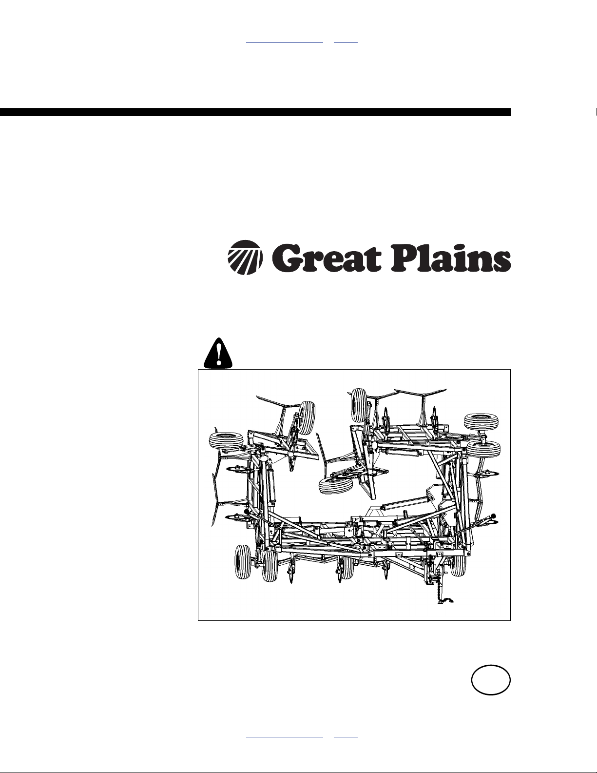
Table of Contents Index
Operator Manual
Plains Plow Series II
9322PP, 9326PP, 9533PP, 9540PP, 9744PP, 9748PP,
9752PP & 9756PP
Manufacturing, Inc.
www.greatplainsmfg.com
Read the operator’s manual entirely. When you see this symbol, the
subsequent instructions and warnings are serious - follow without
exception. Your life and the lives of others depend on it!
41879
Illustrations may show optional equipment not supplied with standard unit.
ORIGINAL INSTRUCTIONS
© Copyright 2014 Printed 2014-02-17 580-043M
Table of Contents Index
EN
Page 2

Table of Contents Index
Table of Contents Index
Page 3

Great Plains Manufacturing, Inc. iii
Table of Contents
Important Safety Information ...................................... 1
Safety Decals ................................................................. 5
Introduction ...............................................................10
Models Covered ........................................................... 10
Description of Unit ........................................................10
Document Family......................................................10
Using This Manual........................................................10
Definitions................................................................. 10
Owner Assistance ........................................................11
Preparation and Setup ...............................................12
Prior to Going to the Field Checklist.............................12
Hitching Tractor to Plains Plow ....................................13
Hydraulic Hose Hookup............................................ 14
Hose Handles...........................................................14
First Time Field Adjustments........................................15
Side to Side Leveling................................................ 15
Operating Instructions...............................................16
Pre-Start Checklist .......................................................16
Transporting ................................................................. 16
Check Tractor Capacity and Configuration...............16
Transport Checklist...................................................16
Folding Instructions for 5 or 7 Section Plains Plow...... 17
5 Section Machines..................................................17
7 Section Machines..................................................17
General Operation and In-Field Adjustments............... 18
Gauge Wheel Adjustment ........................................ 18
Depth Stop ............................................................... 19
Wheel Arm ............................................................... 19
Treader Adjustment.................................................. 20
Treader Angle Adjustment ....................................... 20
Rear Stand ............................................................... 21
Maintenance and Lubrication ................................... 22
Maintenance ................................................................ 22
Lubrication ................................................................... 22
Appendix..................................................................... 24
PP Specifications and Capacities ................................ 24
Tire Inflation Chart ....................................................... 25
Hydraulic Connectors and Torque ............................... 25
Torque Values Chart.................................................... 26
Warranty ...................................................................... 27
Index............................................................................ 29
© Copyright 2006, 2007, 2008, 2009, 2010, 2011, 2012, 2013, 2014 All rights Reserved
Great Plains Manufacturing, Inc. provides this publication “as is” without warranty of any kind, either expressed or implied. While every precaution has been
taken in the preparation of this manual, Great Plains Manufacturing, Inc. assumes no responsibility for errors or omissions. Neither is any liability assumed for
damages resulting from the use of the information contained herein. Great Plains Manufacturing, Inc. reserves the right to revise and improve its products as
it sees fit. This publication describes the state of this product at the time of its publication, and may not reflect the product in the future.
02/17/2014 580-043M
Trademarks of Great Plains Manufacturing, Inc. include: Singulator Plus, Swath Command, Terra-Tine.
Registered Trademarks of Great Plains Manufacturing, Inc. include:
Air-Pro, Clear-Shot, Discovator, Great Plains, Land Pride, MeterCone, Nutri-Pro, Seed-Lok, Solid Stand,
Terra-Guard, Turbo-Chisel, Turbo-Chopper, Turbo Max, Turbo-Till, Ultra-Till, Verti-Till, Whirlfilter, Yield-Pro.
Brand and Product Names that appear and are owned by others are trademarks of their respective owners.
Printed in the United States of America
Page 4

iv 9322-9756PP Great Plains Manufacturing, Inc.
580-043M 02/17/2014
Page 5
Great Plains Manufacturing, Inc. 1
Important Safety Information
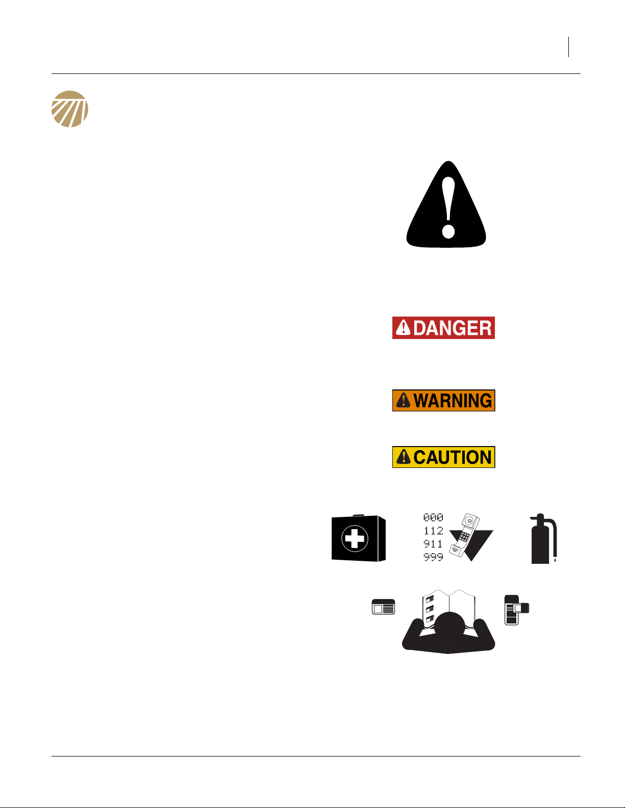
Look for Safety Symbol
The SAFETY ALERT SYMBOL indicates there is a
potential hazard to personal safety involved and extra
safety precaution must be taken. When you see this
symbol, be alert and carefully read the message that follows it. In addition to design and configuration of equipment, hazard control and accident prevention are
dependent upon the awareness, concern, prudence and
proper training of personnel involved in the operation,
transport, maintenance and storage of equipment.
Be Aware of Signal Words
Signal words designate a degree or level of hazard seriousness.
DANGER indicates an imminently hazardous situation
which, if not avoided, will result in death or serious injury.
This signal word is limited to the most extreme situations,
typically for machine components that, for functional purposes, cannot be guarded.
WARNING indicates a potentially hazardous situation
which, if not avoided, could result in death or serious
injury, and includes hazards that are exposed when
guards are removed. It may also be used to alert against
unsafe practices.
CAUTION indicates a potentially hazardous situation
which, if not avoided, may result in minor or moderate
injury. It may also be used to alert against unsafe practices.
Prepare for Emergencies
▲ Be prepared if a fire starts
▲ Keep a first aid kit and fire extinguisher handy.
▲ Keep emergency numbers for doctor, ambulance, hospital
and fire department near phone.
Be Familiar with Safety Decals
▲ Read and understand “Safety Decals” on page 5, thor-
oughly.
▲ Read all instructions noted on the decals.
▲ Keep decals clean. Replace damaged, faded and illegible
decals.
02/17/2014 580-043M
Page 6

2 9322-9756PP Great Plains Manufacturing, Inc.
Wear Protective Equipment
▲ Wear protective clothing and equipment.
▲ Wear clothing and equipment appropriate for the job. Avoid
loose-fitting clothing.
▲ Because prolonged exposure to loud noise can cause hear-
ing impairment or hearing loss, wear suitable hearing protection such as earmuffs or earplugs.
▲ Because operating equipment safely requires your full
attention, avoid wearing entertainment headphones while
operating machinery.
Handle Chemicals Properly
Agricultural chemicals can be dangerous. Improper use
can seriously injure persons, animals, plants, soil and
property.
▲ Read and follow chemical manufacturer’s instructions.
▲ Wear protective clothing.
▲ Handle all chemicals with care.
▲ Avoid inhaling smoke from any type of chemical fire.
▲ Store or dispose of unused chemicals as specified by chemi-
cal manufacturer.
Avoid High Pressure Fluids
Escaping fluid under pressure can penetrate the skin,
causing serious injury.
▲ Avoid the hazard by relieving pressure before disconnecting
hydraulic lines.
▲ Use a piece of paper or cardboard, NOT BODY PARTS, to
check for suspected leaks.
▲ Wear protective gloves and safety glasses or goggles when
working with hydraulic systems.
▲ If an accident occurs, seek immediate medical assistance
from a physician familiar with this type of injury.
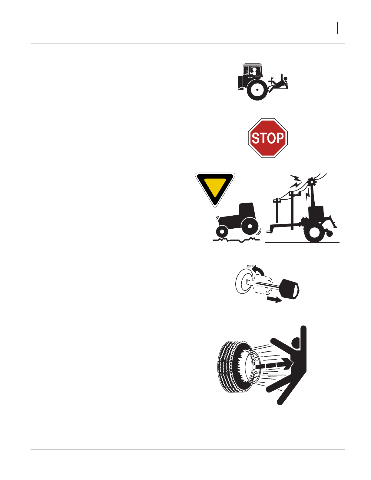
Use Safety Lights and Devices
Slow-moving tractors and towed implements can create
a hazard when driven on public roads. They are difficult
to see, especially at night.
▲ Use flashing warning lights and turn signals whenever driv-
ing on public roads.
Use lights and devices provided with implement
580-043M 02/17/2014
Page 7
Great Plains Manufacturing, Inc. Important Safety Information 3
Keep Riders Off Machinery
Riders obstruct the operator’s view. Riders could be
struck by foreign objects or thrown from the machine.
▲ Never allow children to operate equipment.
▲ Keep all bystanders away from machine during operation.
Transport Machinery Safely
Maximum transport speed for implement is 20 mph (32
kph), 13 mph (22 kph) in turns. Some rough terrains
require a slower speed. Sudden braking can cause a
towed load to swerve and upset.
▲ Do not exceed 20 mph. Never travel at a speed which does
not allow adequate control of steering and stopping. Reduce
speed if towed load is not equipped with brakes.
▲ Comply with state and local laws.
▲ Do not tow an implement that, when fully loaded, weighs
more than 1.5 times the weight of towing vehicle.
▲ Carry reflectors or flags to mark Plains Plow in case of
breakdown on the road.
▲ Keep clear of overhead power lines and other obstructions
when transporting. Refer to transport dimensions under
“PP Specifications and Capacities” on page 24.
▲ Do not fold or unfold the Plains Plow while the tractor is
moving
Shutdown and Storage
▲ Lower Plains Plow, put tractor in park, turn off engine, and
remove the key.
▲ Secure Plains Plow using blocks and supports provided.
▲ Detach and store machine in an area where children nor-
mally do not play.
Tire Safety
Tire changing can be dangerous and should be performed by trained personnel using correct tools and
equipment.
▲ When inflating tires, use a clip-on chuck and extension hose
long enough for you to stand to one side–not in front of or
over tire assembly. Use a safety cage if available.
▲ When removing and installing wheels, use wheel-handling
equipment adequate for weight involved.
02/17/2014 580-043M
Page 8
4 9322-9756PP Great Plains Manufacturing, Inc.
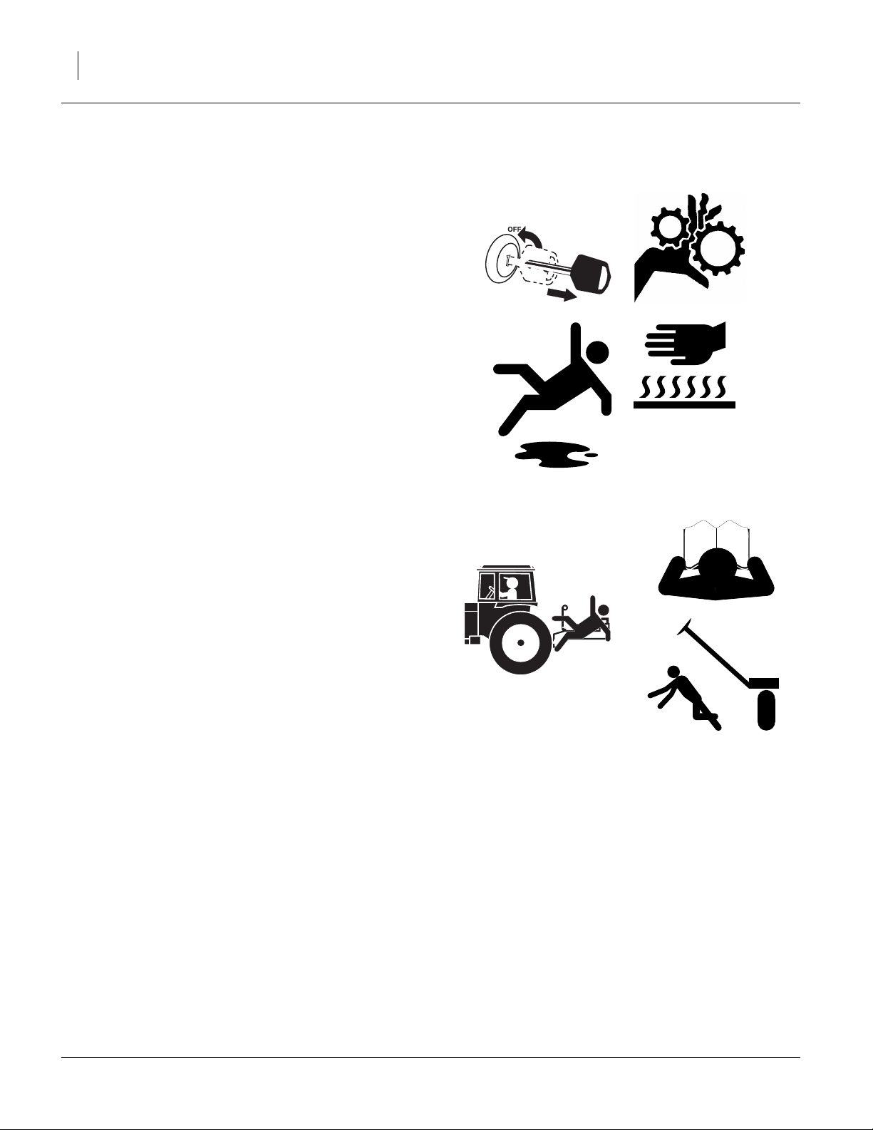
Practice Safe Maintenance
▲ Understand procedure before doing work. Use proper
tools and equipment. Refer to this manual for additional
information.
▲ Work in a clean, dry area.
▲ Lower the machine, put tractor in park, turn off engine,
and remove key before performing maintenance.
▲ Disconnect battery ground cable (-) before servicing or
adjusting electrical systems or before welding on machine.
▲ Inspect all parts. Make sure parts are in good condition
and installed properly.
▲ Remove buildup of grease, oil or debris.
▲ Remove all tools and unused parts from machine before
operation.
Safety At All Times
Thoroughly read and understand the instructions in this
manual before operation. Read all instructions noted on
the safety decals.
▲ Be familiar with all machine functions.
▲ Operate machinery from the driver’s seat only.
▲ Do not leave Plains Plow unattended with tractor engine
running.
▲ Do not stand between the tractor and machine during hitch-
ing.
▲ Keep hands, feet and clothing away from power-driven
parts.
▲ Wear snug-fitting clothing to avoid entanglement with mov-
ing parts.
▲ Watch out for wires, trees, etc., when folding and raising
machine. Make sure all persons are clear of working area.
580-043M 02/17/2014
Page 9
Great Plains Manufacturing, Inc. Important Safety Information 5
Safety Decals
Safety Reflectors and Decals
Your implement comes equipped with all lights, safety
reflectors and decals in place. They were designed to
help you safely operate your implement.
▲ Read and follow decal directions.
▲ Keep lights in operating condition.
▲ Keep all safety decals clean and legible.
▲ Replace all damaged or missing decals. Order new decals
from your Great Plains dealer. Refer to this section for
proper decal placement.
▲ When ordering new parts or components, also request cor-
responding safety decals.
To install new decals:
1. Clean the area on which the decal is to be placed.
2. Peel backing from decal. Press firmly on surface,
being careful not to cause air bubbles under decal.
818-055C
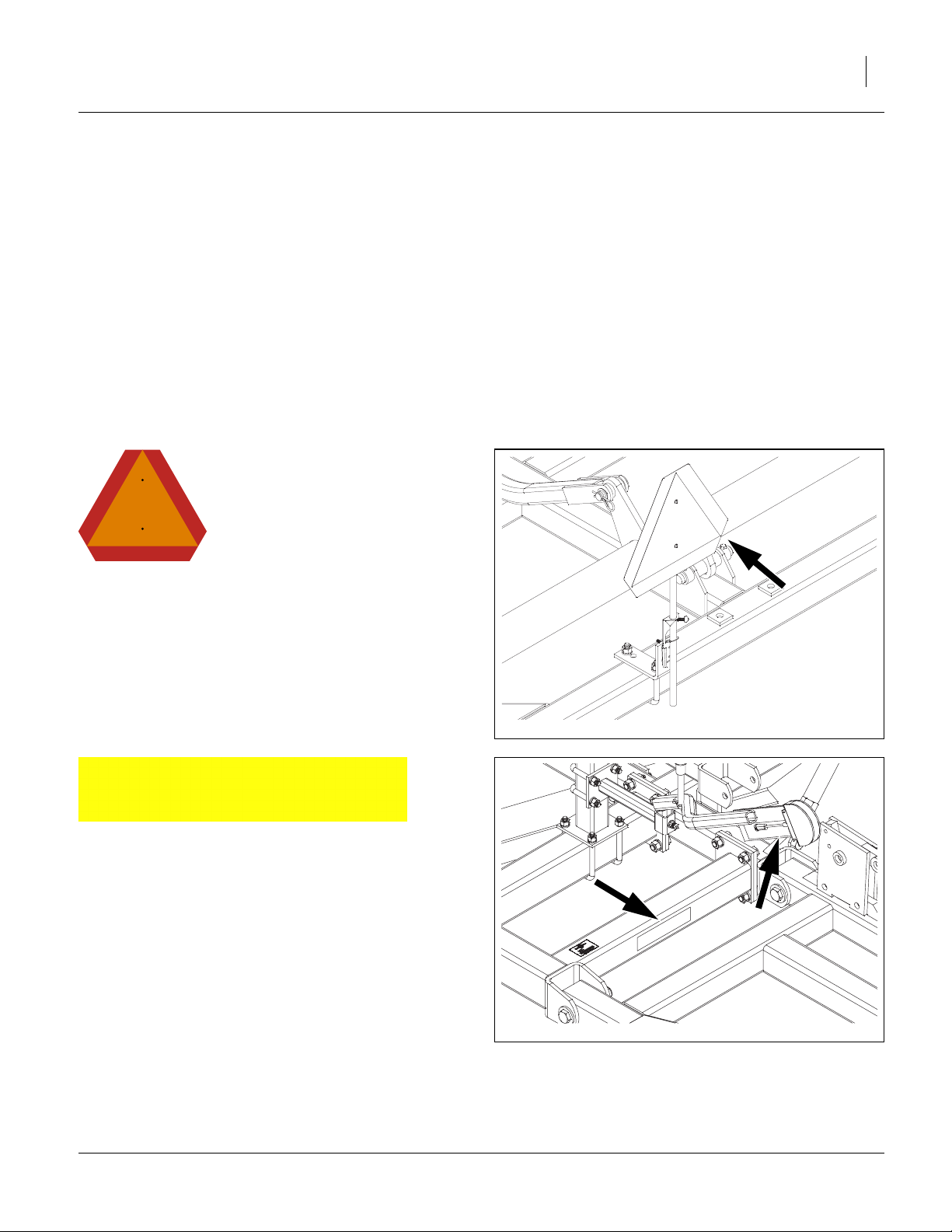
Slow Moving Vehicle Reflector
On the back of the center frame.;
1 total
838-615C
Amber Reflectors
Two on light bracket and two on center frame.Two on rear
of finishing attachment (not shown), visible from side
while folded for transport;
6 total
40762
40763
02/17/2014 580-043M
Page 10
6 9322-9756PP Great Plains Manufacturing, Inc.
40764
838-614C
Red Reflectors
On rear of light brackets (top);.
2 total
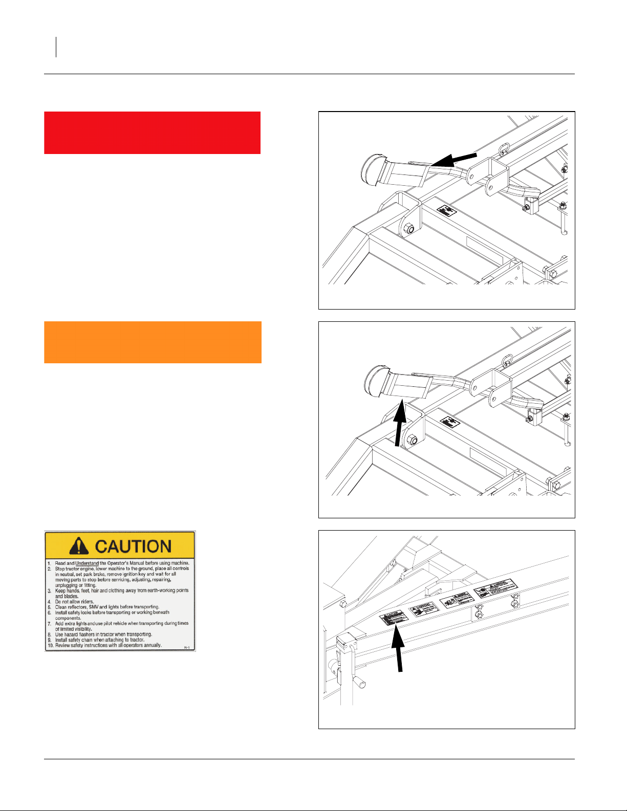
838-603C
Orange Reflectors
On rear of light brackets (bottom);
2 total
40764
838-598C Caution: Read Operator’s Manual
On top, front of hitch;
1 total
580-043M 02/17/2014
40766
Page 11
Great Plains Manufacturing, Inc. Important Safety Information 7
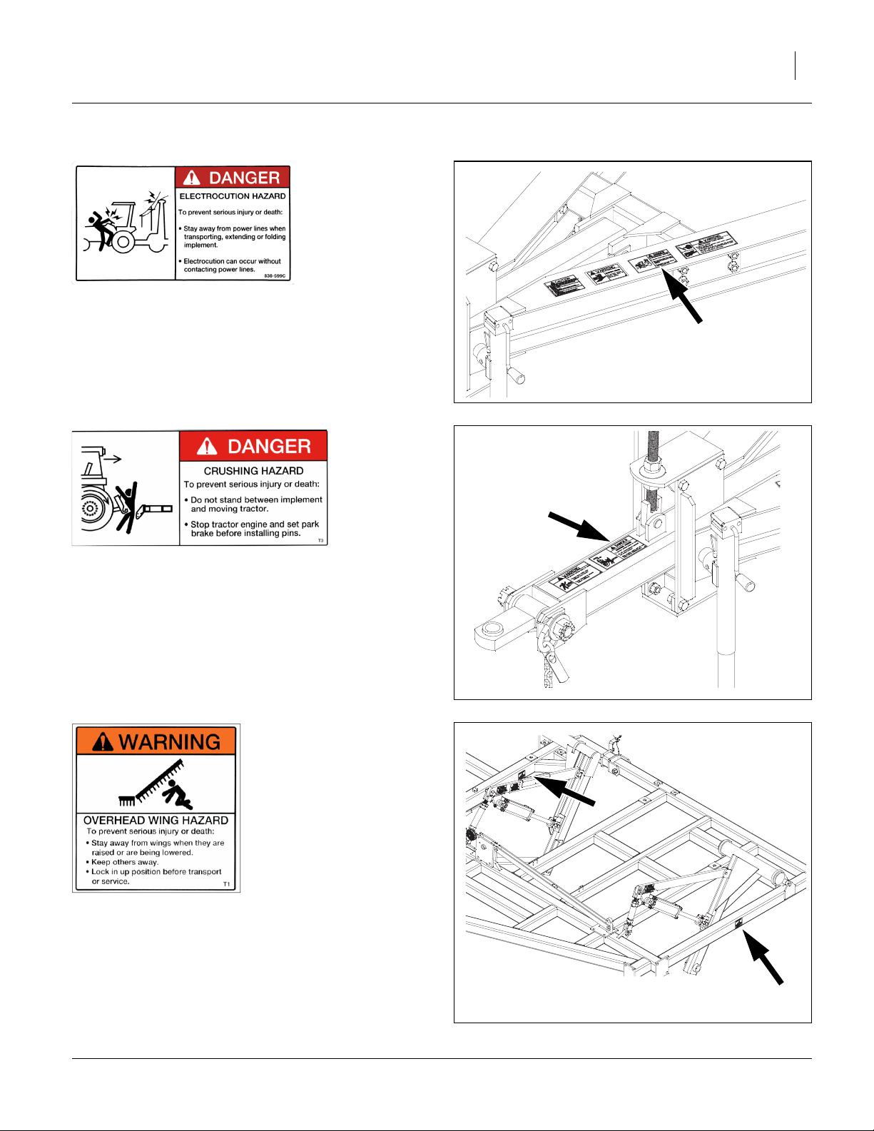
838-599C Danger: Electrocution Hazard
On top, front of hitch;
1 total
40766
40765
838-600C Danger: Crushing Hazard
On front of hitch;
1 total
838-602C Warning: Overhead Wing Hazard
On outside of center and wing frames (both sides);
4 total 3-section
6 total 5-section
7 total 7-section
40767
02/17/2014 580-043M
Page 12

8 9322-9756PP Great Plains Manufacturing, Inc.
838-094C Warning: High Pressure Fluid
On top, front of hitch;
1 total
40766
838-611C Warning: Hand Crushing
On top, front of hitch;
2 total
838-613C Notice: Transport Lock
On outside of center frame, cylinder lift arm (both sides);
2 total
40766
40767
580-043M 02/17/2014
Page 13

Great Plains Manufacturing, Inc. Important Safety Information 9
40768
838-612C Warning: Wings Could Fall Suddenly
On front of wing stop (both sides);
2 total
40765
838-606C Warning: Tongue Rising
On front of hitch;
1 total
848-271C Danger: Cutting of Foot
On outside of cylinder lift arms (both sides);
4 total 3-section
6 total 5-section
8 total 7-section
40767
02/17/2014 580-043M
Page 14

10 9322-9756PP Great Plains Manufacturing, Inc.
Introduction
Great Plains welcomes you to our growing family of new
product owners. The Plains Plow has been designed
with care and built by skilled workers using quality materials. Proper setup, maintenance, and safe operating
practices will help you get years of satisfactory use from
the machine.
Models Covered
9322PP 22-Foot 3-section
9326PP 26-Foot 3-section
9533PP 33-Foot 5-section
9540PP 40-Foot 5-section
9744PP 44-Foot 7-section
9748PP 48-Foot 7-section
9752PP 52-Foot 7-section
9756PP 56-Foot 7-section
R
L
Figure 1
9744PP Plains Plow
R
F
U
B
L
D
43006
Description of Unit
The Plains Plow is a three, five or seven-section V-Blade
undercutting tillage tool. Working width ranges from 22 to
56 feet. The implement is designed to undercut, kill
weeds, apply fertilizers, break up hardpan, manage residue for greater moisture retention and wind erosion protection.
Document Family
580-043Q Pre-Delivery Manual
580-043M Operator Manual (this document)
580-043P Parts Manual
Using This Manual
This manual will familiarize you with
safety, assembly, operation, adjustments, troubleshooting, and maintenance. Read this manual and follow
the recommendations to help ensure safe and efficient
operation.
The information in this manual is current at printing.
Some parts may change to assure top performance.
Definitions
The following terms are used throughout this manual.
A crucial point of information related to the preceding topic.
Read and follow the directions to remain safe, avoid serious
damage to equipment and ensure desired field results.
Note: Useful information related to the preceding topic.
Right-hand and left-hand as used in
this manual are determined by facing
the direction the machine will travel
while in use unless otherwise stated.
An orientation rose in some line art
illustrations shows the directions of:
Up, Back, Left, Down, Front, Right.
R
F
U
B
L
D
580-043M 02/17/2014
Page 15

Great Plains Manufacturing, Inc. Introduction 11
Owner Assistance
If you need customer service or repair parts, contact a
Great Plains dealer. They have trained personnel, repair
parts and equipment specially designed for Great Plains
products.
Refer to Figure 2
Your machine’s parts were specially designed and
should only be replaced with Great Plains parts. Always
use the serial and model number when ordering parts
from your Great Plains dealer. The serial-number plate is
located on the left end of the top front tool bar.
Record your 9322-9756PP Plains Plow model and serial
number here for quick reference:
Model Number:__________________________
Serial Number: __________________________
Your Great Plains dealer wants you to be satisfied with
your new machine. If you do not understand any part of
this manual or are not satisfied with the service received,
please take the following actions.
3. Discuss the matter with your dealership service
manager. Make sure they are aware of any problems
so they can assist you.
4. If you are still unsatisfied, seek out the owner or general manager of the dealership.
Figure 2
Serial Number Plate
For further assistance write to:
Product Support
Great Plains Mfg. Inc., Service Department
PO Box 5060
Salina, KS 67402-5060
40763
(800)255-9215
02/17/2014 580-043M
Page 16

12 9322-9756PP Great Plains Manufacturing, Inc.
Preparation and Setup
This section helps you prepare your tractor and 93229756PP Plains Plow for use, and covers tasks that need
to be done seasonally, or when the tractor/Plains Plow
configuration changes.
Before using the Plains Plow in the field, you must hitch it
to a suitable tractor, inspect systems and level the Plains
Plow. Before using the Plains Plow for the first time, and
periodically thereafter, certain adjustments and calibrations are required.
Prior to Going to the Field Checklist
Complete this checklist before routine setup:
❑ Read and understand “Important Safety Informa-
tion” on page 1.
❑ Check that all working parts are moving freely, bolts
are tight, and cotter pins are spread.
❑ Make sure your tractor horsepower matches the
implement you are pulling. This is important so the
implement can do the best possible job.
❑ Clean all hydraulic couplings and connect to tractor
as shown on page 13 and 14.
❑ If machine is folded, remove the transport pins from
wing stops. (DO NOT remove pins if the wing is leaning against the pins or putting pressure on the pins.
Use the hydraulics to pull the wings in completely
before unpinning them.) Once the pins are removed,
slowly untold the unit. Make sure no one is under the
wings during the unfolding process.
❑ Check again for hydraulic leaks and watch that
hoses do not get pinched in hinges, wing stops, etc.
❑ After the machine is completely unfolded, raise and
lower the Plains Plow several times to purge air from
the hydraulic system. Again check for hydraulic leaks
and tighten or replace if necessary.
❑ Check safety chain hookup. Make sure all warning
lights are hooked up and functioning correctly.
❑ Check that all grease fittings are in place and lubri-
cated. See “Lubrication” on page 22. The hubs will
come pre-greased and will not need greased at this
time.
❑ Check that all safety decals and reflectors are cor-
rectly located and legible. Replace if damaged. See
“Safety Decals” on page 5.
❑ Inflate tires to pressure recommended and tighten
wheel bolts as specified. See “Tire Inflation Chart”
on page 25.
❑ Put transport locks in place and refold the machine
slowly. Put wing stop pins in place. Always use the
transport pins when moving from field to field. You
are now ready to go to the field.
580-043M 02/17/2014
Page 17

Great Plains Manufacturing, Inc. Preparation and Setup 13
Hitching Tractor to Plains Plow
Crushing Hazard:
Do not stand or place any body part between Plains Plow and
moving tractor. You may be severely injured or killed by being
crushed between the tractor and Plains Plow. Stop tractor
engine and set parking brake before attaching cables and
hoses.
To prevent soil compaction on rows, set tractor wheels
between rows. For hillsides and steep slopes, set tractor
wheels as wide as possible for maximum stability.
5. Raise tractor three-point arms (if equipped) clear up
to clear Plains Plow.
6. For TWO-WHEEL DRIVE and MFWD tractors, pin
drawbar in fixed center position for field and transport. For FOUR-WHEEL DRIVE and TRAC-DRIVE
tractors, leave one hole clearance on each side of
drawbar for field position, hitch damage may occur if
pinned solid. Pin in center position for transport to
maintain maximum steering control.
7. Hitch the tractor to the Plains Plow using the block
or yoke clevis determined by the tractor drawbar.
Use the correct size pin for clevis or block.
Load Sway Hazard:
Lock drawbar swing to center position to minimize any sideto-side sway to assure proper tracking in the field, and safe
road travel. See “Transporting” on page 16, for safe trans-
porting
Refer to Figure 3
8. Use jack to raise and lower Plains Plow tongue.
Refer to Figure 4
9. After hitching tractor to Plains Plow, store jack on
storage tube on center brace bar.
10. Secure safety chain to an anchor on the tractor
capable of pulling the unit.
.
1
2
Figure 3
Jack on Tongue
1
43007
2
Figure 4
Jack in Storage
02/17/2014 580-043M
43008
Page 18

14 9322-9756PP Great Plains Manufacturing, Inc.
Hydraulic Hose Hookup
Great Plains hydraulic hoses are color coded to help you
hookup hoses to your tractor outlets. Hoses that go to the
same remote valve are marked with the same color.
Color Hydraulic Function
Black Lift (2 hoses)
Green Fold (2 hoses)
Yellow Fold (2 hoses) (Models 9744-9756 cen-
ter right)
Refer to Figure 5
High Pressure Fluid Hazard:
Relieve pressure before disconnecting hydraulic lines. Use
paper or cardboard, NOT BODY PARTS, to check for leaks.
Wear protective gloves and safety glasses or goggles when
working with hydraulic systems. Escaping fluid under pressure
can have sufficient pressure to penetrate the skin causing serious injury. If an accident occurs, seek immediate medical
assistance from a physician familiar with this type of injury.
Only trained personnel should work on system hydraulics.
Hose Handles
To distinguish hoses on the same hydraulic circuit, refer to,
“Hydraulic Hose Hookup” above. The hose under an
extended symbol feeds a cylinder base end. The hose
under a retracted-cylinder symbol feeds a cylinder rod end.
Clean all hydraulic couplings and hook hoses to tractor.
Figure 5
Hose Handles
580-043M 02/17/2014
41552
Page 19

Great Plains Manufacturing, Inc. Preparation and Setup 15
First Time Field Adjustments
Pre-Leveling of Machine
Side to Side Leveling
Refer to Figure 6
11. Pre-leveling of machine can be done on a concrete slab
or level surface. Lower machine so sweeps are 1” off of
ground on the center frame. Adjust the long turnbuckles
1
at the front of the frames that do not fold, by loosening jam nut and turning center part of turnbuckle to
an initial setting of 19” pin center to center Check the
center frame for level, if one side is higher than the
other side, extend that side, turnbuckle to bring the center level. (Shorten to bring up, extend to bring down).
12. Retighten jam nut .
13. After the center frame is level, do the same for each
wing frame moving outward from the center frame. The
first folding wing (short) turnbuckle initial setting is 17”
pin center to center. The second folding wing (short)
turnbuckle initial setting is 16 3/4”.
14. Make any minor adjustments to these setting to level
the machine (shorten to bring up, extend to bring down).
The wings may need to be adjusted slightly lower than
the center in soft field conditions.
2 3
2
2
3
Lift Turnbuckle Adjustment
4
1
4
Figure 6
40991
Do not adjust turnbuckle with machine lifted up. Turnbuckle may
disassemble and cause machine to fall. Turnbuckle maximum center to center length is 17 3/4”
15. If machine is equipped with coulters, set coulters at 1”
to 1 1/2” above the depth of the sweep blades.
16. You are now ready to operate the machine in the field.
02/17/2014 580-043M
Page 20

16 9322-9756PP Great Plains Manufacturing, Inc.
Operating Instructions
This section covers general operating procedures. Experience, machine familiarity, and the following information
will lead to efficient operation and good working habits.
Always operate farm machinery with safety in mind.
Pre-Start Checklist
Perform the following steps before transporting the 93229756PP Plains Plow to the field.
❑ Carefully read “Important Safety Information” on
page 1.
❑ Lubricate Plains Plow as indicated under “Lubrica-
tion” on page 22.
❑ Check all tires for proper inflation.
❑ Check all bolts, pins, and fasteners. Torque as shown
in “Tire Inflation Chart” on page 25.
❑ Check Plains Plow for worn or damaged parts.
Repair or replace parts before going to the field.
Check hydraulic hoses, fittings, and cylinders for leaks.
Repair or replace before going to the field.
High Pressure Fluid Hazard:
Relieve pressure and shut down tractor before connecting, disconnecting or checking hydraulic lines. Use a piece of paper
or cardboard, NOT BODY PARTS, to check for leaks. Wear
protective gloves and safety glasses or goggles when working
with hydraulic systems. Escaping fluid under pressure can
have sufficient pressure to penetrate the skin causing serious
injury. If an accident occurs, seek immediate medical assistance from a physician familiar with this type of injury.
Transporting
See “Hitching Tractor to Plains Plow” on page 13
before transporting the Plains Plow.
Check Tractor Capacity and Configuration
• Consult your tractor manual for 3-point limitations.
• Add weights to tractor as required.
When determining the weight of your Plains Plow, be
sure to include the weight of any options.
Transport Checklist
❑ Plan the route. Avoid steep hills. Keep Clearances in
mind.
❑ Make all electrical and hydraulic connections. See
“Hitching Tractor to Plains Plow” on page 13.
❑ Raise Plains Plow.
❑ Be sure all transport locks are installed.
❑ Always have lights on for highway operation.
❑ Comply with all federal, state and local safety laws
when traveling on public roads.
Travel with caution. Allow safe clearance.
Remember that the Plains Plow is wider than the tractor.
Loss of Control Hazard:
Use a tractor rated for the load. Add tractor ballast as needed.
Do not exceed 20 mph. Towing the Plains Plow with a vehicle
that is not adequate, or at high speeds, could lead to loss of
vehicle control. Loss of vehicle can result in a serious road
accident, severe injury or death. Check that your tractor has
enough weight to handle the weight of the Plains Plow. Refer to
your tractor’s operator manual for capacities and ballast
requirements.
580-043M 02/17/2014
Page 21

Great Plains Manufacturing, Inc. Operating Instructions 17
Folding Instructions for 5 or 7 Section Plains Plow
5 Section Machines
17. When operating the plains plow, the hydraulic flow
settings for the lift system may be set at or near full
flow to allow optimum lift and lower cycle times. The
fold system flow settings should be reduced to 10-15
gpm (usually 1/2 full flow on most tractors). This will
prevent damage to the fold system during the folding
and unfolding process.
18. When folding the machine to transport position, it is
important that the outside wing is folded completely
before inner wings begin to fold. If the inner wings
are folding at the same time as the outer wings, the
hydraulic flow is too high and will cause damage to
the machine. Reduce the flow! In some cases, if the
flow settings are difficult to change, when the inside
wing begins to fold before the outside wing is completely folded, center the fold lever. This will allow for
the oil to transfer from the outer cylinders to the inner
cylinders and the inside wings will fall. Once the outside wings are completely folded, proceed with folding the inner wings.
19. When unfolding the machine, the inner wings need
to be completely unfold before the outer wings begin
to unfold. If the outer wings are unfolding at the same
time as the inner, the flow is too high and damage
may occur. If adjusting the flow is difficult on your
tractor, you may need to center the hydraulic lever at
some point to allow the inside wings to stay ahead of
the outer wing. Once the inner wings are completely
to the ground, continue the unfolding process for the
outer wings.
7 Section Machines
20. When folding or unfolding 7 section machines, it is
important that the hydraulic flow is not too high, 1015 gallon per minute is more than adequate for folding or unfolding. On most tractors, this is about 1/2
the maximum flow available. Prior to unfolding the
plains plow, remove all transport safety pins. Do not
remove pins if there is pressure against pins. If pressure exists, pull all the cylinders in, to relieve the
pressure from pins.
21. After pins are removed, close the small cylinder
between the two sections that remain on the ground.
This will make these sections temporarily rigid.
Begin the unfolding process. Make sure the inner
wings unfold ahead of the outer wings. If the outer
wings are unfolding along with the inner, slow the
flow down. If this continues at a slower flow rate, center the hydraulic lever to allow the inner wings to get
ahead of the outer wings. Once the inner wings are
completely unfolded, continue to unfold the outer
wings. Once the outer wings are unfolded completely, extend the small cylinders between the center sections to allow these to flex in the field.
22. When folding the 7 section machines, first close the
small cylinder between the 2 sections that remain on
the ground. Star the unfolding process. Make sure
the outside wings fold completely before the inside
wings start to fold. If the inner wings begin to fold too
early, slow the outer wings to get ahead of the inner.
Once the outside wings are folded completely, fold
the inner wings and then the left hand inner most
wing. Once unit is completely folded, extend the
small cylinder between the two sections on the
ground to allow the sections to flex during transport.
Note: Failure to follow these steps may cause damage
to the fold cylinders and to the folding mechanisms
and will void the manufactures warranty of these
parts.
02/17/2014 580-043M
Page 22

18 9322-9756PP Great Plains Manufacturing, Inc.
General Operation and In-Field Adjustments
23. Remove the transport lock pins and unfold the
machine. Make sure the fold cylinders are fully
extended to fully flex in the field.
24. If possible have someone observe the machine during
first time operation for levelness, front to rear and
wings to center frame.Adjust each as needed.
Front to Rear Leveling
Refer to Figure 7
25. Lower the machine to the desired working depth and
then level the machine from front to rear if needed.
Model 9322 will have a turnbuckle to adjust and models
9326-9756 will have an eyebolt (shown). Loosen jam
1 2
nut on either the turnbuckle or eyebolt and adjust
other nut up or down, moving front of hitch until
machine is level front to rear for most conditions.
Retighten jam nut to secure.
26. The front could be adjusted slightly lower for hard soils.
Do not adjust too much lower. Never run machine with
the back lower (deeper) than the front.
27. Once the machine is leveled front to rear the treaders
may be adjusted. In most cases the treader should be
allowed to float and will not require additional down
pressure.
28. The machine may need some additional adjustment
from side to side, See “Side to Side Leveling” on
page 15. Adjust the inside wings first, then the outside
wings.
1 3
1
1
3
2
Figure 7
Hitch Adjustment
40992
Gauge Wheel Adjustment
Refer to Figure 8
29. Once the machine has been adjusted and set to the
desired working depth, you may now adjust the gauge
wheels.
30. To adjust the gauge wheel arm , loosen the two 3/4
2 3 1
bolts . Remove pin and slide gauge wheel arm up
or down until the gauge wheel is 1/2” to 1 1/2” above
ground.
31. Re-instal the pin and tighten the two 3/4 bolts .
32. The ideal working speed for the Plains Plow is 5 1/2 to 6
1/2 mph. Working too slow may cause plugging, poor
incorporation or mixing crop residue and reduced weed
kill. Running too fast may cause streaks in chemical
incorporation and ridging.
580-043M 02/17/2014
3 2
1
3
1
Figure 8
Gauge Wheel Adjustment
2
43012
Page 23

Great Plains Manufacturing, Inc. Operating Instructions 19
Depth Stop
Refer to Figure 9.
33. Once the machine is level and set to the desired depth,
set the depth stop at the front of the machine to
ensure that the unit will operate at a consistent depth
every pass. After setting the stop, if a change of depth is
desired, 1 full turn of the handle either in or out will
change the depth approximately 1/4” up or down respectively.
Note: If after setting the depth stop, the detent on the tractor
kicks out before the stop contacts the button on the
depth stop, slow the hydraulic flow speed down. If this
problem persists, contact the factory service representative for other possible adjustments. On tractors with a
timed detent setting, set the detent so when you raise
the machine, the pump will run for 1/2 to 1 full second
after full raise. If it runs longer than this, damage to the
seals of the lift cylinders may result. If the problem still
persists, contact the factory service representative for
the possible adjustments.
Note: Do not try to adjust the rebound valve without contact-
ing the factory service rep.
1
3
1
2
3
2
Figure 9
Depth Stop Adjustment
42250
Wheel Arm
Refer to Figure 10
34. If the tire on the outside wings , on models 9533,
9744 and 9748, are riding in loose or already worked
ground and running too deep, you can correct the problem by moving the wheel arms to the optional position
as shown. Start by lowering machine to ground until
wheel arm pins are loose. Remove both wheel arm
pins , rear cylinder arm bolt , and rod end cylinder
pin . Switch the RH and LH wheel arms side to side
and move wheel arm linkage over to inside lug on
front of frame. Re-install all pins and bolts to secure. This
will move the tires inward 5” to let wings run level.
1 2
3
4
4 5
6 3
7
1
4
1
3
6 5
7
2
Figure 10
Wheel Arm
4
41347
02/17/2014 580-043M
Page 24

20 9322-9756PP Great Plains Manufacturing, Inc.
Treader Adjustment
Refer to Figure 11
35. Adjust the treaders to leave the desired result. In most
cases the treader should be allowed to float and will not
require additional down pressure. The spring bolt
should be pre-set in the 3rd hole (normal position) of
treader mount bracket .
36. To increase down pressure and make the treaders more
aggressive, the spring bolt may be moved forward to
the 2nd hole of treader mount bracket , from front. This
will also reduce transport height so you may need to
tighten the nut at the top of the spring bolt to raise the
treaders up slightly for transport.
1
4
2
2
3
2
3
4
1
3
Treader Angle Adjustment
Refer to Figure 12
37. The treaders are designed to be run at angles of either
15° or 20°.15° is the preferred setting in most instances.
To set the treader gangs to 15°, install the 3/4 x 4 bolt
in the inside hole of treader gang tube . For 20°,
2 1
install in outside hole of treader gang tube .
38. If plugging of the treaders occurs, they may need to be
moved back one hole in the wishbone arm assemblies.
The further back you move these the more tail heavy the
unit is. Do not move them unless absolutely necessary.
Note: Most of the extra mounting holes in the brackets are
needed to allow our treaders to be mounted on competitors machines. Under most circumstances, it is not
necessary to vary the settings from the factory recommended settings for our machines.
1
1
Figure 11
Treader Adjustment
2
1
Figure 12
Treader Angle Adjustment
43013
43041
580-043M 02/17/2014
Page 25

Great Plains Manufacturing, Inc. Operating Instructions 21
Rear Stand
Refer to Figure 13
If machine is equipped with a rear attachment, be sure you install
the rear jack stand so machine doesn’t tip backwards when unhooking machine from tractor.
39. Attach the rear stand bracket to the center of, the rear
tube of the drag frame with 5/8 x 4 1/32 x 5 1/2 u-bolts ,
5/8 lock washers and 5/8 nuts.
40. Tighten u-bolts specs, See “Torque Values Chart” on
page 26.
41. Slide the rear stand through the rear stand bracket ,
secure with the 3/4 x 4 3/8 pin and retainer.
42. Once the options are installed, fold the plains plow to
check for clearance and interferences, also watch that
hoses do not get pinched.
Note: Double check that all bolts are tightened to specs, See
“Torque Values Chart” on page 26.Consult the “Oper-
ator’s Manual”, for the first time field adjustments before
going to the field.
3 1
1
2
4
2
4
Figure 13
Rear Stand
1
3
43039
02/17/2014 580-043M
Page 26

22 9322-9756PP Great Plains Manufacturing, Inc.
Maintenance and Lubrication
Maintenance
1. Always use the transport lock when working on or
doing maintenance to the Plains Plow. If folded, be
sure your wing stop pins are in place. Read and
understand all safety decals on your equipment.
2. During the first season of operation, and periodically
after that, check your bolts for tightness. Check
shank pivot bolts for tightness. Check coulter mounting and frog bolts for tightness.
3. Replace or rotate worn parts as needed -- hinge
bolts, clevis pins, bearings, sweeps, shanks, etc.
4. Check and tighten or replace any hydraulic leaks.
Check hoses for any leaks. It is important that there
are no leaks on the equipment.
5. Grease wheel bearings and walking beams sparingly. Over greasing may cause damage to seals and
reduce the life of the bearing. Grease hinge points
periodically.
6. Check drag bolts for loosness or excessive wear.
Replace broken or bent teeth. Your drag is an important part of the tillage operation.
7. If machine is stored outdoors over the winter months,
it is a good idea to fold the machine then set it down
on the ground so all the cylinders are retracted to
protect the cylinder rods. This will extend the life of
the cylinder seals and reduce internal and external
leaks.
By following and maintaining a routine service and lubrication program, your tillage equipment will give you
many years of service.
For the most current manual information, visit Great
Plains website listed below. For more information on
operating, adjusting or maintaining your Great
Plains, Plains Plow, assistance is available. Contact:
Product Support
Great Plains Mfg. Inc., Service Department
PO Box 5060
Salina, KS 67402-5060
(800)255-9215
Lubrication
Multipurpose
spray lube
Wheel Bearing Hub
Multipurpose
grease lube
50
1 zerk on each hub;
all hubs
Type of Lubrication: Grease
Quantity: Sparingly, Do Not Over Grease, may cause damage
to seal.
Repack wheel bearings annually or every 2500 acres.
Multipurpose
oil lube
41622
Intervals (service hours)
at which lubrication is
50
required
580-043M 02/17/2014
Page 27

Great Plains Manufacturing, Inc. Maintenance and Lubrication 23
Walking Beam Pivot Bearings
100
One on each walking beam
Type of Lubrication: Grease
Quantity: Sparingly and check for endplay
If there is a lot of end play take apart, check bearings
and re-pack
41730
All Hinge Points
10
One on each bearing
Type of Lubrication: Grease
Quantity: Grease every 10 hours, until grease
emerges.
Treader Gang Bearings
50
One on each bearing
Type of Lubrication: Grease
Quantity: Grease every 50 hours, 2 to 3 pumps. In
heavy conditions grease every 20 hours, 2 to 3 pumps.
43010
43010
02/17/2014 580-043M
Page 28

24 9322-9756PP Great Plains Manufacturing, Inc.
Appendix
PP Specifications and Capacities
Model No. 9322PP 9326PP 9533PP 9540PP
Tillage Width 22' 4" (681cm) 26' 0" (792cm) 33' 4"(1016cm) 40' 8" (1243cm)
Center Section 7' 6" (229cm) 10' 0" (305cm) 10' 0" (305cm) 10' 0" (305cm)
Wing (1st) 8' 0" (244cm) 8' 0" (244cm) 7' 0" (213cm) 8' 0" (244cm)
Wing (2nd) N/A N/A 4' 0" (122cm) 7' 0" (213cm)
Wing (3rd) N/A N/A N/A N/A
Number of Sweeps 67 911
Weight (Approximate) 8160 lbs. (3701 kg) 9220 lbs. (4182 kg) 11500 lbs. (5216 kg) 13480 lbs. (6114 kg)
Transport Width 13' 0" (396cm) 16' 8" (509cm) 18' 0" (549cm) 18' 0" (549cm)
Transport Height 12' 6" (381cm) 12' 6" (381cm) 14' 6" (442cm) 13' 6" (441cm)
Tire Size (Center) 11L-15SL 12 ply 11L-15 8 ply 11L-15SL 12 ply 11L-15SL 12 ply
Tire Size (Wing) 11L-15 8 ply 11L-15 8 ply 11L-15 8 ply 11L-15 8 ply
Tire Size (Gauge Wheel) 9.5L-15 8 ply 9.5L-15 8 ply 9.5L-15 8 ply 9.5L-15 8 ply
Horsepower (PTO) 150-205 180-240 230-305 285-370
Kilowatt 112-153 135-179 172-227 213-276
Model No. 9744PP 9748PP 9752PP 9756PP
Tillage Width 44' 4" (1351cm) 48' 0" (1463cm) 51' 8" (1578cm) 55' 4" (1687cm)
Center Section 7 6" (229cm) 10' 0" (305cm) 7' 6" (229cm) 10' 0" (305cm)
Wing (1st) 7' 6" (229cm) 7' 0" (213cm) 7' 6" (229cm) 7' 6" (229cm)
Wing (2nd) 7'' 0" (213cm) 7' 0" (213cm) 8' 0" (244cm) 8' 0" (244cm)
Wing (3rd) 4' 0" (122cm) 4 0" (122cm) 7' 0" (213cm) 7' 0" (213cm)
Number of Sweeps 12 13 14 15
Weight (Approximate) 17300 lbs. (7847 kg) 18620 lbs. (8446 kg) 19220 lbs. (8718 kg) 20540 lbs. (9317 kg)
Transport Width 21' 10" (666cm) 25' 6" (777cm) 21' 10" (666cm) 25' 6" (777cm)
Transport Height 14' 6" (442cm) 14' 6" (442cm) 14' 6" (442cm) 14' 6" (442cm)
Tire Size (Center & Inner Wing) 11L-15 Load F 11L-15 Load F 11L-15 Load F 11L-15 Load F
Tire Size (Outer Wings) 11L-15 8 ply 11L-15 8 ply 11L-15 8 ply 11L-15 8 ply
Tire Size (Gauge Wheel) 9.5L-15 8 ply 9.5L-15 8 ply 9.5L-15 8 ply 9.5L-15 8 ply
580-043M 02/17/2014
Page 29

Great Plains Manufacturing, Inc. Appendix 25
Tire Inflation Chart
Tire Inflation Chart
Wheel Tire Size Inflation
Gauge
Wheel
Transport/
Wing
Transport/ 11Lx15” 12-Ply
Transport/ 11Lx15” Load F
9.5Lx15” 8-Ply
11L x 15” 8-Ply
44 psi
303 kPa
36 psi
248 kPa
52 psi
359 kPa
90 psi
621 kPa
All tires are warranted by the original manufacturer of the tire.
Tire warranty information is found in the brochures included with
your Operator’s and Parts Manuals or online at the manufacturer’s web sites listed below. For assistance or information, contact your nearest Authorized Farm Tire Retailer.
Manufacturer Web site
Firestone www.firestoneag.com
Gleason www.gleasonwheel.com
Titan www.titan-intl.com
Galaxy www.atgtire.com
BKT www.bkt-tire.com
Hydraulic Connectors and Torque
Refer to Figure 14 (a hypothetical fitting)
Leave any protective caps in place until immediately prior
to making a connection.
1
NPT - National Pipe Thread
Note tapered threads, no cone/flare, and no O-ring.
Apply liquid pipe sealant for hydraulic applications.
Do not use tape sealant, which can clog a filter and/or
plug an orifice.
2
JIC - Joint Industry Conference (SAE J514)
Note straight threads and the 37° cone on
“M” fittings (or 37° flare on “F” fittings).
Use no sealants (tape or liquid) on JIC fittings.
3
ORB - O-Ring Boss (SAE J514)
Note straight threads and elastomer O-Ring .
Prior to installation, to prevent abrasion during tightening, lubricate O-Ring with clean hydraulic fluid.
Use no sealants (tape or liquid) on ORB fittings.
ORB fittings that need orientation, such as the ell
depicted, also have a washer and jam nut
(“adjustable thread port stud”). Back jam nut away
from washer. Thread fitting into receptacle until
O-Ring contacts seat. Unscrew fitting to desired
orientation. Tighten jam nut to torque specification.
4 5
5 7
8 9
5
Dash
Size
-4
-5
-5
-5
-6
-6
-6
-8
-8
-8
Tire Warranty Information
1
9
8
4
2
Figure 14
Hydraulic Connector ID
Fittings Torque Values
Fitting N-m Ft-Lbs
1
⁄4-18 NPT 1.5-3.0 turns past finger
tight
1
⁄2-20 JIC 19-20 14-15
1
⁄2-20 ORB w/jam nut 12-16 9-12
1
⁄2 -20 ORB straight 19-26 14-19
5
⁄16-18 JIC 24-27 18-20
5
⁄16-18 ORB w/jam nut 16-22 12-16
5
⁄16-18 ORB straight 24-33 18-24
3
⁄4 -16 JIC 37-53 27-39
3
⁄4 -16 ORB w/jam nut 27-41 20-30
3
⁄4-16 ORB straight 37-58 27-43
7
5
3
31282
02/17/2014 580-043M
Page 30

26 9322-9756PP Great Plains Manufacturing, Inc.
Torque Values Chart
Bolt
Size
in-tpi
1
⁄4-20
1
⁄4-28
5
⁄16-18
5
⁄16-24
3
⁄8-16
3
⁄8-24
7
⁄16-14
7
⁄16-20
1
⁄2-13
1
⁄2-20
9
⁄16-12
9
⁄16-18
5
⁄8-11
5
⁄8-18
3
⁄4-10
3
⁄4-16
7
⁄8-9
7
⁄8-14
1-8
1-12
1
1
⁄8-7
1
1
⁄8-12
1
⁄4-7
1
1
⁄4-12
1
3
⁄8-6
1
3
1
⁄8-12
1
1
⁄2-6
1
1
⁄2-12
Bolt Head Identification
Grade 2 Grade 5 Grade 8 Class 5.8 Class 8.8 Class 10.9
a
b
d
N-m
ft-lb
7.4 11 16
8.5 13 18
15 24 33
17 26 37
27 42 59
31 47 67
43 67 95
49 75 105
66 105 145
75 115 165
95 150 210
105 165 235
130 205 285
150 230 325
235 360 510
260 405 570
225 585 820
250 640 905
340 875 1230
370 955 1350
480 1080 1750
540 1210 1960
680 1520 2460
750 1680 2730
890 1990 3230
1010 2270 3680
1180 2640 4290
1330 2970 4820
N-m N-m
5.6 8 12
61014 5 811
11 17 25 12 19 27
13 19 27 13 21 29
20 31 44 24 39 53
22 35 49 29 45 62
32 49 70 42 67 93
36 55 78 44 70 97
49 76 105 66 77 105
55 85 120 68 105 150
70 110 155 73 115 160
79 120 170 105 165 230
97 150 210 115 180 245
110 170 240 145 230 300
170 265 375 165 260 355
190 295 420 205 325 450
165 430 605 230 480 665
185 475 670 355 560 780
250 645 910 390 610 845
275 705 995 705 1120 1550
355 795 1290 785 1240 1710
395 890 1440 1270 1950 2700
500 1120 1820 1380 2190 3220
555 1240 2010
655 1470 2380
745 1670 2710
870 1950 3160
980 2190 3560
Bolt Head Identification
Bolt
Size
ft-lb ft-lb ft-lb ft-lb ft-lb
mm x pitch
M 5 X 0.8
M 6 X 1
M 8 X 1.25
M 8 X 1
M10 X 1.5
M10 X 0.75
M12 X 1.75
M12 X 1.5
M12 X 1
M14 X 2
M14 X 1.5
M16 X 2
M16 X 1.5
M18 X 2.5
M18 X 1.5
M20 X 2.5
M20 X 1.5
M24 X 3
M24 X 2
M30 X 3.5
M30 X 2
M36 X 3.5
M36 X 2
a. in-tpi = nominal thread diameter in inches-threads per inch
b. N· m = newton-meters
c. mm x pitch = nominal thread diameter in mm x thread pitch
d. ft-lb = foot pounds
c
5.8 8.8 10.9
N-m N-m N-m
357
71115
17 26 36
18 28 39
33 52 72
39 61 85
58 91 125
60 95 130
90 105 145
92 145 200
99 155 215
145 225 315
155 240 335
195 310 405
220 350 485
280 440 610
310 650 900
480 760 1050
525 830 1150
960 1510 2100
1060 1680 2320
1730 2650 3660
1880 2960 4100
946
Torque tolerance + 0%, -15% of torquing values. Unless otherwise specified use torque values listed above.
25199m
25199
Wheel Bolt Torque Values 1/2”-20 (75-85 ft-lbs) 9/16”-18 (80-90 ft-lbs) 5/8”-18 (85-100 ft-lbs)
580-043M 02/17/2014
Page 31

Great Plains Manufacturing, Inc. Appendix 27
Warranty
Great Plains Manufacturing, Incorporated warrants to the original purchaser that this tillage
and workmanship for a period of one year from the date of original purchase when used as intended and under normal service and conditions
for personal use; 90 days for commercial or rental purposes. This Warranty is limited to the replacement of any defective part by Great Plains
Manufacturing, Incorporated and the installation by the dealer of any
such replacement part. Great Plains reserves the right to inspect any
equipment or part which are claimed to have been defective in material
or workmanship.
This Warranty does not apply to any part or product which in Great
Plains’ judgement shall have been misused or damaged by accident or
lack of normal maintenance or care, or which has been repaired or altered in a way which adversely affects its performance or reliability, or
which has been used for a purpose for which the product is not designed. This Warranty shall not apply if the product is towed at a speed
in excess of 20 miles per hour.
Claims under this Warranty must be made to the dealer which originally
sold the product and all warranty adjustments must by made through
such dealer. Great Plains reserves the right to make changes in materials or design of the product at any time without notice.
This Warranty shall not be interpreted to render Great Plains liable for
damages of any kind, direct, consequential, or contingent, to property.
Furthermore, Great Plains shall not be liable for damages resulting from
any cause beyond its reasonable control. This Warranty does not extend to loss of crops, losses caused by harvest delays or any expense
or loss for labor, supplies, rental machinery or for any other reason.
No other warranty of any kind whatsoever, express or implied, is
made with respect to this sale; and all implied warranties of merchantability and fitness for a particular purpose which exceed
the obligations set forth in this written warranty are hereby disclaimed and excluded from this sale.
This Warranty is not valid unless registered with Great Plains Manufacturing, Incorporated within 10 days from the date of original purchase.
equipment will be free from defects in material
42134
02/17/2014 580-043M
Page 32

28 9322-9756PP Great Plains Manufacturing, Inc.
580-043M 02/17/2014
Page 33

Great Plains Manufacturing, Inc. 29
Index
A
address, Great Plains ............. 11, 22
amber reflectors ................................. 5
B
bearings ........................................... 22
bolts ................................................. 22
C
Caution
Read Operator’s Manual .............. 6
CAUTION, defined ............................. 1
chain ................................................ 13
checklists
pre-setup .................................... 12
pre-start ...................................... 16
transport ..................................... 16
chemicals ........................................... 2
children .............................................. 3
clothing ............................................... 2
color code, hose ............................... 14
contact Great Plains ................ 11
covered models ................................ 10
customer service .............................. 11
, 22
D
Danger
Crushing Hazard .......................... 7
DANGER, defined .............................. 1
decal replacement .............................. 5
decals
caution
read manual ........................... 6
Danger
Cutting of Foot ........................ 9
danger
crushing .................................. 7
electrocution ........................... 7
notice
transport lock .......................... 8
speed
30km per hr ............................ 9
warning
hand crushing ......................... 8
high pressure fluid .................. 8
overhead wing ........................ 7
tongue rising ........................... 9
wings could fall ....................... 9
decal, safety ....................................... 5
definitions ......................................... 10
depth stop ........................................ 19
directions .......................................... 10
drag bolts ......................................... 22
E
email, Great Plains .................. 11, 22
F
fire ...................................................... 1
G
gauge wheel adjustment .................. 18
H
headphones ....................................... 2
hearing ............................................... 2
high pressure fluids ........................... 2
hills .................................................. 13
hitch adjustment .............................. 18
hitching ............................................ 13
hose handles ................................... 14
hydraulic connectors ........................ 25
hydraulic safety .................................. 2
I
inflation ............................................ 25
J
JIC ................................................... 25
Joint Industry Conference ................ 25
J514 ................................................. 25
K
kPa ................................................... 25
L
leaks ..........................................2, 22
left-hand, defined ............................. 10
lights .................................................. 2
lubrication ........................................ 22
all hinge points ........................... 23
treader gang bearings ................ 23
M
Maintenance .................................... 22
maintenance safety ............................ 4
medical assistance ........... 2
model number .................................. 11
, 14, 16
N
National Pipe Thread ....................... 25
Note, defined ................................... 10
Notice, defined ................................. 10
NPT ................................................. 25
O
orange reflector ................................. 6
ORB ................................................. 25
orientation rose ................................ 10
O-Ring Boss .................................... 25
owner assistance ............................. 11
P
parts ................................................ 22
phone number, GP .......................... 12
Pre-leveling of machine ................... 15
protective equipment ......................... 2
psi .................................................... 25
R
rear jack stand ................................. 21
red reflectors ...................................... 6
reflectors
amber ........................................... 5
orange .......................................... 6
red ................................................ 6
SMV ............................................. 5
reflectors, safety ................................. 5
repair parts .......................................11
riders .................................................. 3
right-hand, defined ........................... 10
rose, oriention ..................................10
S
SAE J514 ......................................... 25
safety chain ......................................13
safety decal ........................................5
safety information ............................... 1
safety symbol ..................................... 1
serial number ...................................11
setup ................................................12
shutdown ............................................ 3
slopes ............................................... 13
SMV (Slow Moving Vehicle) ...............5
Spanish ....................................... 6
Specifications and Capacities .......... 24
speed .................................................7
storage ............................................... 3
storing machine ................................ 22
support .................................... 11
symbol, safety .................................... 1
, 7
, 22
T
tables
document family ......................... 10
fittings torque ..............................25
hose color code ..........................14
models covered ..........................10
torque values ..............................26
tire inflation ....................................... 25
tires ....................................................3
transport ...........................................16
transport lock ....................................22
transport speed .................................. 3
transporting ...................................... 16
treader adjustment ........................... 20
U
URLs, tires .......................................25
W
walking beam pivot ...........................23
WARNING, defined ............................1
warranty ...................................25
welding ...............................................4
wheel arm adjustment ......................19
Wheel Bearing Hub ..........................22
Wing Depth Adjustment .......... 15
www .................................................25
, 27
, 18
Numerics
13 mph ............................................... 3
20 mph ...................................... 3
22 kph ................................................3
32 kph ................................................3
580-043M, manual ........................... 10
580-043P, manual .............................10
580-043Q, manual ...........................10
818-055C, reflector .............................5
, 16
02/17/2014 580-043M
Page 34

30 9322-9756PP Great Plains Manufacturing, Inc.
838-094C, decal ................................. 8
838-598C, decal ................................. 6
838-599C, decal ................................. 7
838-600C, decal ................................. 7
838-602C, decal ................................. 7
838-603C, reflector .............................6
838-606C, decal .................................9
838-611C, decal .................................8
838-612C, decal .................................9
838-613C, decal .................................8
838-614C, reflector ............................6
838-615C, reflector ............................5
848-271C, decal ................................. 9
580-043M 02/17/2014
Page 35

Page 36

Great Plains Manufacturing, Inc.
Corporate Office: P.O. Box 5060
Salina, Kansas 67402-5060 USA
 Loading...