

Page 1
Operator’s Manual
60303P and 80303P
Three-Point Planter
Model Serial No.
60303P F1079 and Earlier
80303P G1021 and Earlier
Manufacturing, Inc.
P.O. Box 5060 ● Salina, Kansas 67402-5060
Read the operator’s manual entirely. When you see this symbol, the subsequent in-
!
structions and warnings are serious - follow without exception. Your life and the lives of
others depend on it!
© Copyright 1999 Printed
03/02/99
14911
Cover illustration may show optional equipment not supplied with standard unit.
401-008M
Page 2

General Information
General Information
Important Notice
Great Plains Manufacturing, Inc. provides this publication “as is” without warranty of any kind, either
expressed or implied, while every precaution has been
taken in the preparation of this manual, Great Plains
Manufacturing, Inc. assumes no responsibility for errors
or omissions. Neither is any liability assumed for damages resulting from the use of the information contained
herein. Great Plains Manufacturing, Inc. reserves the
right to revise and improve its products as it sees fit. This
publication describes the state of this product at the time
of its publication, and may not reflect the product at all
times in the future.
Printed in the United States of America.
For your convenience, record your serial number, model
number and the date purchased in the spaces provided
below. Have this information before you when calling a
Great Plains Authorized Dealer.
This Operator’s Manual applies to the 6-Row/8-Row 3-Point Planter listed below:
401-001A 6-Row 30" Planter
401-002A 8-Row 30" Planter
Owner’s Information
Name: _____________________________________
Address ____________________________________
City________________State ____ Zip ___________
Phone_______________________
Name of Dealership ___________________________
Dealer’s Name _______________________________
Address ____________________________________
City________________State ____ Zip ___________
Phone_______________________
Serial Number _______________________________
Model Number _______________________________
Date Purchased ______________________________
60303P and 80303P Three-Point Planter 401-008M 5/15/06Great Plains Mfg., Inc.
Page 3

Table of Contents
Table of Contents
Using this Manual . . . . . . . . . . . . . . . . . . . . . . . . . . 2
Introduction. . . . . . . . . . . . . . . . . . . . . . . . . . . . . . . . 2
Section 1 Safety Rules . . . . . . . . . . . . . . . . . . . . . . . 3
General Operation & Repair. . . . . . . . . . . . . . . . . 3
Transporting . . . . . . . . . . . . . . . . . . . . . . . . . . . . . 3
Tire Handling & Repair . . . . . . . . . . . . . . . . . . . . . 3
Agricultural Chemicals . . . . . . . . . . . . . . . . . . . . . 3
Safety Decals . . . . . . . . . . . . . . . . . . . . . . . . . . . . 4
Section 2 Planter Operation. . . . . . . . . . . . . . . . . . . 6
Initial Preparation of the Planter . . . . . . . . . . . . . . 6
Tractor Preparation . . . . . . . . . . . . . . . . . . . . . . . . 6
Attaching the Planter to the Tractor . . . . . . . . . . . 6
Transporting . . . . . . . . . . . . . . . . . . . . . . . . . . . . . 7
Leveling the Planter . . . . . . . . . . . . . . . . . . . . . . . 7
Section 3 Row Unit Operation . . . . . . . . . . . . . . . . . 8
Finger Pickup Meter . . . . . . . . . . . . . . . . . . . . . . . 8
Seed Hopper . . . . . . . . . . . . . . . . . . . . . . . . . . . . 9
Chemical Hopper . . . . . . . . . . . . . . . . . . . . . . . . . 9
Seed and Chemical Meter Drive Adjustments . . . 9
Down Force Springs. . . . . . . . . . . . . . . . . . . . . . 10
Row Unit Mounted Coulter . . . . . . . . . . . . . . . . . 11
Depth Adjustment. . . . . . . . . . . . . . . . . . . . . . . . 11
1 x 12 Closing Wheel Adjustments. . . . . . . . . . . 11
Closing Disk Adjustments. . . . . . . . . . . . . . . . . . 12
Seed Lok . . . . . . . . . . . . . . . . . . . . . . . . . . . . . . 13
Section 4 Adjusting Planting Rates . . . . . . . . . . . 14
Planting Rates . . . . . . . . . . . . . . . . . . . . . . . . . . 14
Adjusting Granular Chemical Rates . . . . . . . . . . 15
Planting Rates for Finger Pickup Corn Meters. . 16
Granular Chemical Rate Charts . . . . . . . . . . . . . 22
Section 5 Troubleshooting. . . . . . . . . . . . . . . . . . . 23
Finger Pickup Corn Meter . . . . . . . . . . . . . . . . . 23
Section 6 Lubrication . . . . . . . . . . . . . . . . . . . . . . . 24
Section 7 Maintenance. . . . . . . . . . . . . . . . . . . . . . 26
Fasteners . . . . . . . . . . . . . . . . . . . . . . . . . . . . . . 26
Finger Pickup . . . . . . . . . . . . . . . . . . . . . . . . . . . 26
Spreader and Scraper . . . . . . . . . . . . . . . . . . . . 27
Disk . . . . . . . . . . . . . . . . . . . . . . . . . . . . . . . . . . 27
Gauge Wheels . . . . . . . . . . . . . . . . . . . . . . . . . . 27
Shear Pins . . . . . . . . . . . . . . . . . . . . . . . . . . . . . 27
Chain Tension . . . . . . . . . . . . . . . . . . . . . . . . . . 27
Outside Scrapers . . . . . . . . . . . . . . . . . . . . . . . . 27
Chain Routing Diagram . . . . . . . . . . . . . . . . . . . 28
Maintenance & Lubrication Record . . . . . . . . . . 29
Section 8 Storage . . . . . . . . . . . . . . . . . . . . . . . . . . 30
Section 9 Specifications . . . . . . . . . . . . . . . . . . . . 31
Torque Values Chart. . . . . . . . . . . . . . . . . . . . . . 33
Tire Inflation Chart . . . . . . . . . . . . . . . . . . . . . . . 33
Metric Conversion Chart . . . . . . . . . . . . . . . . . . 34
Section 10 Attachments & Options. . . . . . . . . . . . 35
Section 11 Warranty . . . . . . . . . . . . . . . . . . . . . . . . 36
5/15/06 Great Plains Mfg., Inc.
60303P and 80303P Three-Point Planter 401-008M
-1
Page 4
Using this Manual
Using this Manual
For your safety and to help in developing a better understanding of your equipment we highly recommend that
you read the operator sections of this manual. Reading
these sections not only provides valuable training but
also familiarizes you with helpful information and its lo-
Introduction
This manual has been prepared to instruct you in the
safe and efficient operation of your 6-Row/8-Row 3Point Planter. Read and follow all instructions and safety
precautions carefully.
Read and follow all instructions and safety precautions
carefully.
The parts on your 6-Row/8-Row 3-Point Planter have
been specially designed and should only be replaced
with genuine Great Plains parts. Therefore, should your
6-Row/8-Row 3-Point Planter require replacement parts
go to your Great Plains Dealer.
The right hand and left hand as used throughout this
manual is determined by facing in the direction the machine will travel when in use unless otherwise stated.
Serial Number
The serial number plate is located on the left hand side
of the upper hitch plate. It is suggested that the serial
number and purchase date also be recorded for your
convenience in the space provided on the checklist
page at the beginning of this manual.
The serial number provides important information about
your Planter and may be required to obtain the correct
replacement part. Always use the serial number and
model number when sending correspondence or when
ordering parts from your Great Plains Dealer.
cation. The parts sections are for reference only and
don’t require cover to cover reading. After reviewing
your manual store it in a dry, easily accessible location
for future reference.
safety precautions must be taken. When you see this
symbol, be alert and carefully read the message that follows it. In addition to design and configuration of
equipment; hazard control and accident prevention are
dependent upon the awareness, concern, prudence and
proper training of personnel involved in the operation,
transport, maintenance and storage of equipment.
Watch for the following safety notations throughout your Operators Manual:
!
DANGER!
Indicates an imminently hazardous situation which, if
not avoided, will result in death or serious injury. This
signal word is limited to the most extreme situations.
!
WARNING!
Indicates a potentially hazardous situation which, if not
avoided, could result in death or serious injury.
!
Indicates a potentially hazardous situation which, if not
avoided, may result in minor or moderate injury. It may
also be used to alert against unsafe practices.
CAUTION!
!
The SAFETY ALERT SYMBOL indicates that there is a
potential hazard to personal safety involved and extra
2
60303P and 80303P Three-Point Planter 401-008M 5/15/06
NOTE: Indicates a special point of information which
requires your attention.
Great Plains Mfg., Inc.
Page 5

Section 1 Safety Rules
Section 1 Safety Rules
Most accidents are the result of negligence and carelessness, usually caused by failure of the operator to
follow simple but necessary safety precautions. The following safety precautions are suggested to help prevent
such accidents. The safe operation of any machinery is
a big concern to consumers and manufactures. Your
3-Point Planter has been designed with many built-in
safety features. However, no one should operate this
product before carefully reading this Operators Manual.
General Operation & Repair
1. Practice safety by always thinking before acting.
2. Never allow the planter to be operated by anyone who is
unfamiliar with the operation of all functions of the unit.
All operators should read and thoroughly understand the
instructions given in this manual prior to moving the
unit.
3. Make sure safety rules are understood before operating
machine or tractor.
4. Never permit any persons other than the operator to ride
on the tractor.
5. Regulate your speed to the field conditions, maintaining
complete control at all times.
6. Always lower the implement and shut off the tractor engine before making any adjustments.
7. After repairing or adjusting, make sure all tools and
parts are removed from the implement before attempting
to operate it.
8. Never work under a raised planter.
9. Do not grease or oil machine while it is in operation.
10. Loose fitting clothing should not be worn as it may catch
in moving parts.
11. Never attempt to operate the implement unless you are in
the driver’s seat.
12. Never dismount from a moving tractor.
13. Do not leave the tractor or the implement unattended
with the engine running.
14. Do not stand between the tractor and the implement during hitching.
15. Always make sure there are no persons near the planter
when the marker assemblies are in operation.
16. Watch for obstructions such as wires, tree limbs etc.,
when folding markers.
17. disk edges are sharp! Be careful when working in this area.
18. Detach and store implements in an area where children
normally do not play. Stabilize implements by using suitable supports and block wheels.
19. If a hydraulic leak develops, correct it immediately. Escaping hydraulic oil can have extremely high pressure. A
stream of high pressure oil may easily penetrate the skin
as with modern needless vaccination equipment - but
with the exception that hydraulic fluid may cause blood
poisoning. It is imperative that the connections are tight
and that all lines and pipes are in good condition. If an
injury is caused by the escaping hydraulic fluid, see doctor at once!
20. Use a piece of cardboard or wood to detect leaks of hydraulic oil under pressure.
21. Be sure to relieve all hydraulic pressure before disconnection any lines or pipes between the implement and the tractor hydraulic system. Keep all guards and shields in place.
Transporting
1. Use good judgement when transporting tractor implements on the highway. Always maintain complete control
of the machine.
2. Limit transport speed to 20 mph. Transport only with a
farm tractor of sufficient size and horse power. (See
“Section 2 Planter Operation” on page 6)
3. Always make sure “Slow Moving Vehicle” emblem, and
reflectors are in place and visible prior to transporting
the machine on public roads.
4. Know your state and local laws concerning highway
safety and regulations. Comply with these laws when
transporting machinery.
Tire Handling & Repair
1. Tire changing can be dangerous and should be preformed by trained personnel using the correct tools and
equipment.
2. Do not re-inflate a tire that has been run flat or seriously
under inflated. Have it checked by qualified personnel.
3. When removing and installing wheels, use wheel handling equipment adequate for the weight involved.
Agricultural Chemicals
1. Agricultural chemicals can be dangerous. Always select
the correct chemical for the job. Improper usage of fertilizers, fungicides, herbicides, insecticides, and pesticides could cause injury to all living things.
2. Always read instructions supplied by the manufactures
before opening chemical containers. Read and follow instructions supplied by the chemical manufacturer carefully before each use.
3. Apply the same precautions when adjusting, servicing,
cleaning, or storing the planter as you would when putting chemicals into the planter.
4. Inform anyone who may come in contact with chemicals,
or a planter with chemicals, of any potential hazard or
safety precaution that should be observed.
5. Avoid inhaling smoke from any type of chemical fire.
6. Store or dispose of all unused chemicals as specified by
the chemical manufacturer.
5/15/06 Great Plains Mfg., Inc.
60303P and 80303P Three-Point Planter 401-008M
-3
Page 6
Section 1 Safety Rules
Safety Decals
1. Your 3-Point Planter comes equipped with all safety decals in place. They were designed to help you safely operate your planter. Read and follow their directions.
2. Keep safety decals clean and legible.
3. Replace all damaged or missing safety decals. To order
new safety decals go to your Great Plains Dealer and refer
to the parts section for safety decal package part number.
4. Replace these decals whenever they become worn or unreadable. See the parts section for the correct location of
these decals. To install new safety decals:
a. Clean the area the decal is to be placed
b. Peel backing from the decal. Press firmly on to
surface being careful not to cause air bubbles under
the decal.
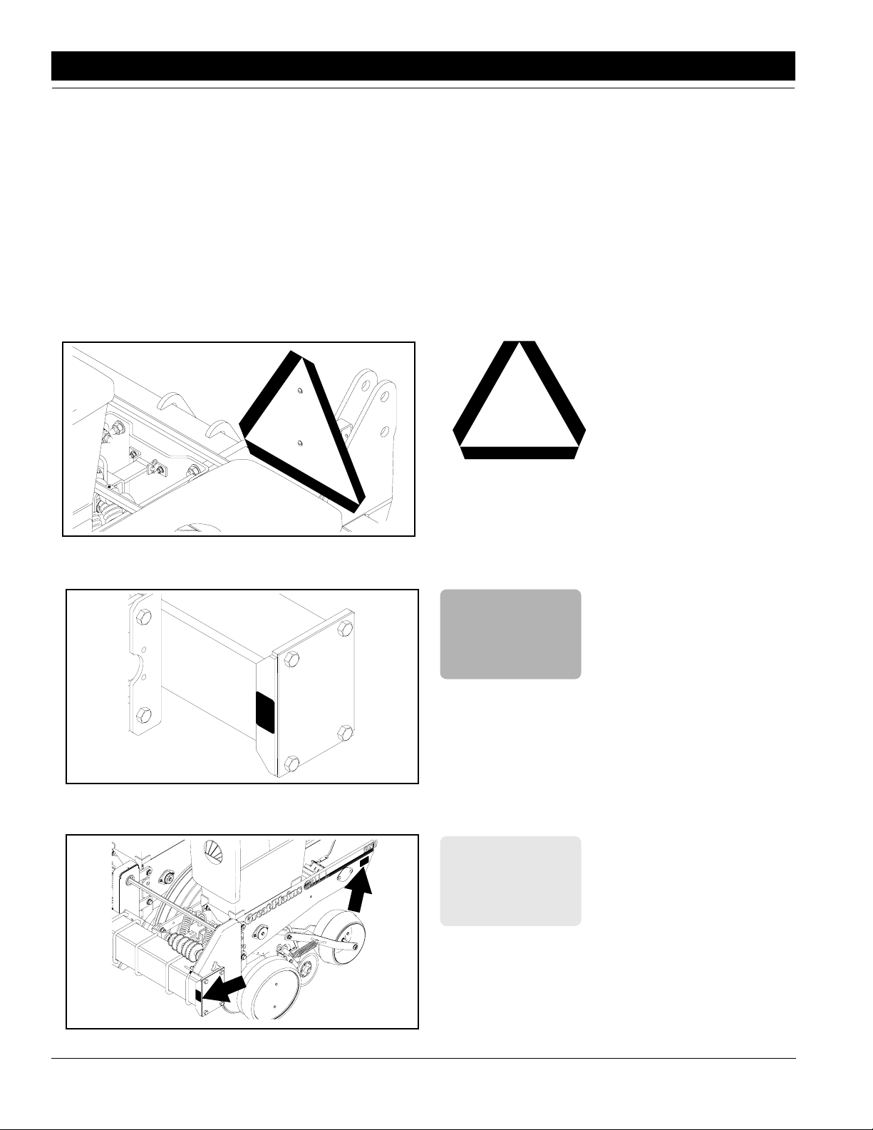
12414
12356
818-003C
Slow Moving Vehicle Emblem
818-230C
Red Reflectors
818-229C
Amber Reflectors
12357
4
60303P and 80303P Three-Point Planter 401-008M 5/15/06
Great Plains Mfg., Inc.
Page 7
Section 1 Safety Rules
12359
12392
!
CAU-
AGRICULTURAL CHEMICALS CAN BE
DANGEROUS. IMPROPER SELECTION OR
USE CAN SERIOUSLY INJURE PERSONS,
ANIMALS, PLANTS, SOIL OR OTHER
PROPERTY. BE SAFE. SELECT
THE RIGHT CHEMICAL FOR THE JOB. HANDLE
IT WITH CARE. FOLLOW THE INSTRUCTIONS
ON THE CONTAINER LABEL.
PRECAUTIONS SHOULD BE TAKEN TO
PREVENT EXPOSURE. PROTECTIVE
CLOTHING AND EQUIPMENT IS TO BE
WORN. REFER TO THE OWNERS MANUAL
FOR INFORMATION ABOUT THE PROTECTIVE
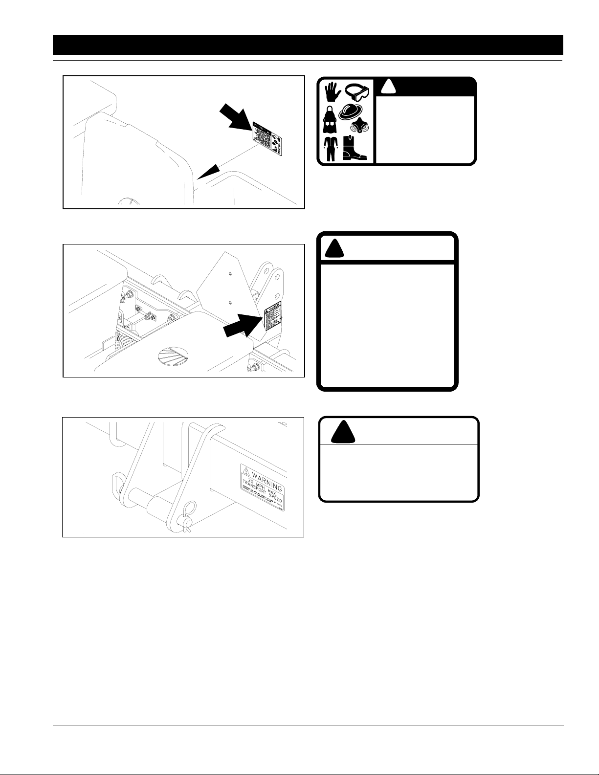
818-323C
Ag Chemicals Caution
(Located inside the chemical lid)
CAU-
!
- Read Operator’s Manual before
operating planter
- Stand clear when folding and
unfolding markers
- Stand clear when raising and
lowering planter
- Keep hands and clothing away
from moving chains and sprockets
- Never ride on the planter
- Always lower or properly support
the planter before servicing
- Escaping hydraulic fluid can
cause serious injury.
818-399C
818-323C
818-399C
Planter Operational Cautions
12415
!
WARNING
20 MPH MAX.
TRANSPORT SPEED
EXCEEDING 20 MPH MAY RESULT IN LOSS OF VEHICLE
CONTROL AND/OR IMPLEMENT DAMAGE
818-188C
Transport Speed Warning
818-188C
5/15/06 Great Plains Mfg., Inc.
60303P and 80303P Three-Point Planter 401-008M
-5
Page 8
Section 2 Planter Operation
Section 2 Planter Operation
The following section was written to provide general information on the planter and tractor operation.
Initial Preparation of the Planter
•
Lubricate the planter and markers as shown in
“Section 6 Lubrication” on page 24.
• Check the tires for proper inflation, refer to the Tire In-
flation Chart in "Section 9 Specifications" on
page 33.
• Check the chains for proper tension and alignment as
shown in "Section 7 Maintenance" on page 28.
• Perform all beginning of season and daily planter ser-
vice as discussed in “Section 8 Storage” on
page 30.
• Check over the planter and replace worn or damaged
parts before going to the field.
• All nuts, bolts and screws should be checked per the
Torque Value Chart in "Section 9 Specifications" on
page 33.
• The legs of the cotter pins should be spread.
Tractor Preparation
Recommended Tractor Horsepower
Minium required draw bar horsepower for field work
6-row planter 60 - 90 HP
8-row planter 80 - 120 HP
2. Adjust the tractor lower lift links to maximize lifting
height.
NOTE: To keep the planter level make sure that the
lower lift links are adjusted evenly.
Set the tractor sway blocks to minimize side sway.
Position the lift controls in float position.
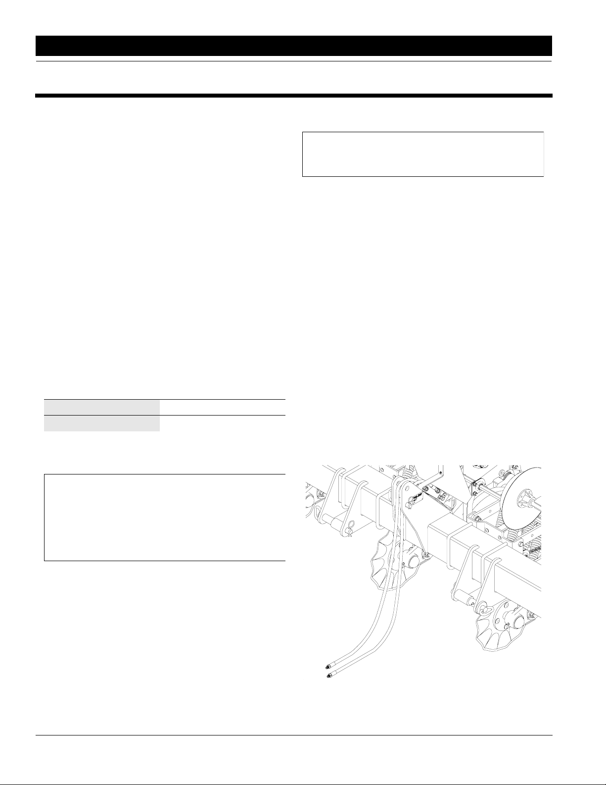
3. Back the tractor up to the planter. Align the lower
links with the lower hitch holes on the planter. Insert
the hitch pins and the spacers, supplied with the
planter, according to the category of your tractor,
Figure 2-1. Lock the pins in place.
4. There are two holes on the planter for the upper
hitch point. The the tractor’s top link should be attached in the lower hole for Category II, see Figure
2-1. Some Category II quick couplers and all Category III top links should be attached in the upper hole,
Figure 2-1. To attach the top link some adjustment
may be required.
5. Raise the planter and look for any interference while
standing between the planter row units. Remove the
pin holding the parking stand and raise the stands to
the transport position. Put the pin in the lowest hole
in each stand, see Figure 2-1. Never work under a
raised Planter.
6. On level ground, lower the planter onto the gauge
wheels. If the planter is not level see Leveling the
Planter page 7.
NOTE: The tractor must have adequate 3 point hitch
lift capacity to lift the machine weight, attachments,
seeds and dry chemicals. Shipping weights, (refer to
“Section 9 Specifications” on page 31), do not include seed, dry chemicals or optional attachments.
For tractor front end stability additional tractor ballast
may be required. Add front ballast according to your
tractor's operator’s manual.
Attaching the Planter to the Tractor
For the planter to function properly, attach the planter to
the tractor in the following manner.
1. Set the tractor wheels at double the planter row
spacing. Example: For a planter with 30" rows the
front and rear wheels should be set at 60" center to
center. This prevents soil compaction on the rows.
On hillsides andsteep slopes set the wheels as wide
as possible for maximum stability.
6
60303P and 80303P Three-Point Planter 401-008M 5/15/06
12340
Hitch on Planter
Figure 2-1
Great Plains Mfg., Inc.
Page 9
Section 2 Planter Operation
Transporting
!
The planter should never be transported faster than
20 miles per hour!
Before transporting the planter, check and practice the
following items:
CAUTION!
•The planter can be transported with full boxes of seed.
It is best NOT to because the extra weight increases
the chances for problems on the road. Do not exceed
20 miles per hour.
NOTE: In order to maintain steering control, ballast
may need to be added to tractor front end. To determine the amount of ballast required refer to your tractor’s operator manual.
•Check to see that the gauge tires on the planter have
the proper inflation as listed in the Tire Inflation Chart
in "Section 9 Specifications" on page 33.
•Comply with all Federal, State and Local Safety Laws
when traveling on public roads.
•Remember, the planter is wider than the tractor and
extreme care must be taken to allow for safe clearance.
Leveling the Planter
The planter must be level for the row units to function
correctly. Before leveling the planter check tire pressures as specified in the Tire Inflation Chart in “Section
9 Specifications” on page 31.
Adjust the lower links on the tractor to level the planter
side to side. It is best to adjust the links evenly before the
planter is attached to the tractor.
After setting the row units to the proper planting depth in
the field, stop the tractor on flat ground with the planter
lowered. Check the front-to-back level of the planter.
The bottom of the frame tube should be parallel to the
ground. If this is not parallel, adjust the upper link on the
tractor accordingly. See Figure 2-3.
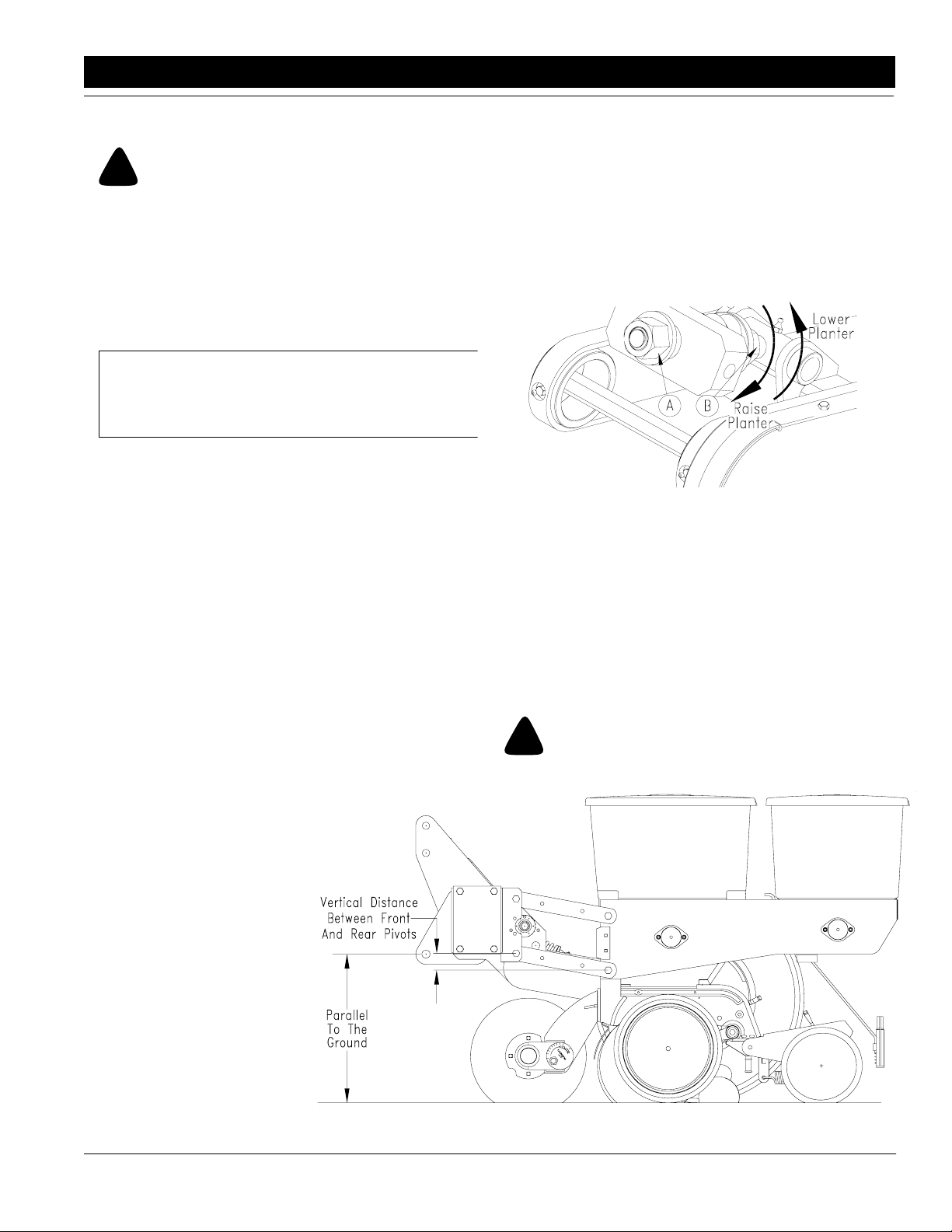
If the row unit arms are not parallel to the ground, the
gauge wheel modules must be adjusted equally. Measure the vertical distance between the front pivot and
10495
Gauge Wheel Module Adjustment
Figure 2-2
rear pivot of a row unit arm, see Figure 2-2. This is the
amount that the gauge wheel needs to be adjusted.
Raise the planter and loosen the jam nut (A) on the
wheel module. To lower the planter, turn the nut (B) at
the opposite end of the link counter-clockwise and clockwise to raise the planter, see Figure 2-2. Tighten the jam
nut after reaching the desired wheel location.
!
Never work under the planter while in the raised position.
WARNING!
Leveling the Planter
Figure 2-3
5/15/06 Great Plains Mfg., Inc.
60303P and 80303P Three-Point Planter 401-008M
12466
-7
Page 10
Section 3 Row Unit Operation
Section 3 Row Unit Operation
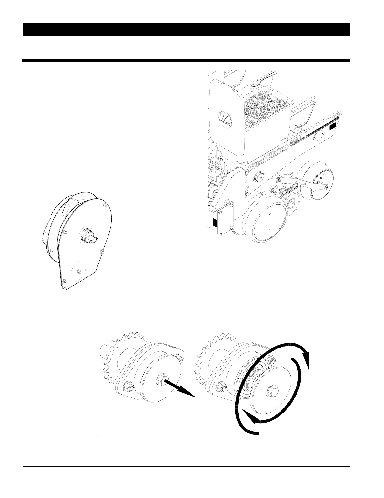
Finger Pickup Meter
This planter is equipped with a 12 finger mechanical
corn meter see Figure 3-1. Refer to the Planter Rate for
Finger Pickup CornMeter chart in “Section 4 Adjusting
Planting Rates” on page 14 for adjusting the planting
rates and sprocket combinations.
IMPORTANT: To extend the life and maximize efficiency of the finger pickup meter, sprinkle 1 teaspoon of
powdered graphite on top of the seeds in the hopper,
see Figure 3-2. The graphite will work its way down to
lubricate the meter mechanism.
For more information on the meter, see “Section 5
Troubleshooting” on page 23 & “Section 7 Maintenance” on page 26.
12341
Finger Pickup
Meter
Figure 3-1
12342
Graphite Applied To
Top Of Seeds
Figure 3-2
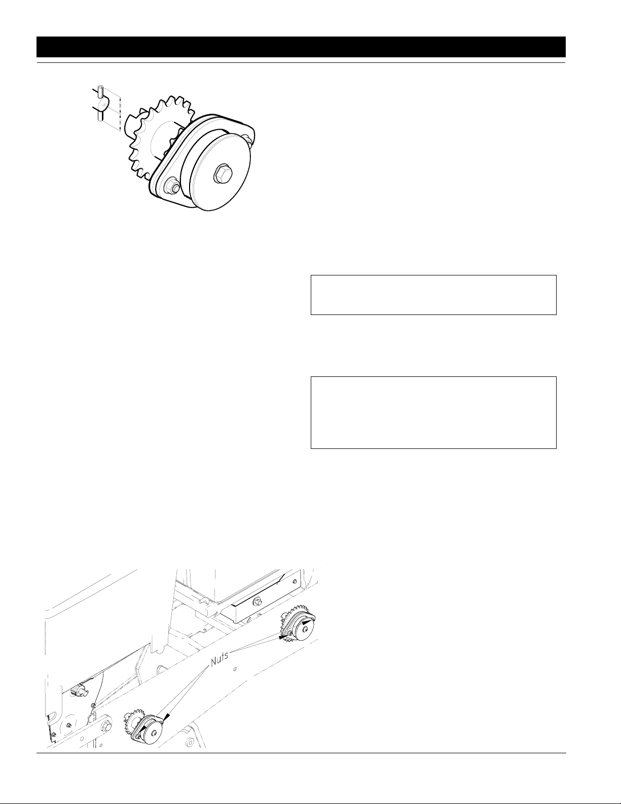
Meter Clutches
To disengage either the seed hopper clutch or the chemical hopper clutch pull the knob and rotate 30 degrees
clockwise or counter-clockwise until the points on the
hex shaft align with the indentations in the end of the
drive hub then release knob. See Figure 3-3.
To engage the clutches, pull and rotate the knob until the
shaft aligns with the drive hub then release.
12467
Disengage Meter Clutch
Figure 3-3
8
60303P and 80303P Three-Point Planter 401-008M 5/15/06
Great Plains Mfg., Inc.
Page 11
Section 3 Row Unit Operation
Seed Hopper
The row unit is equipped with one 2-bushel translucent
seed hopper.
Before filling the seed hopper, clear it of foreign objects.
After filling the hopper with clean seeds always replace
the hopper lid. Operating with the lids attached prevents
objects from entering the hopper and also aids in keeping out moisture.
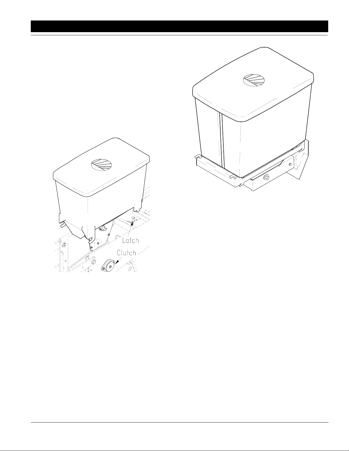
Empty the contents of the hopper periodically to avoid
the collection of dirt and other materials. To remove the
hopper, disengage the meter drive clutch and the hopper latch, see arrows Figure 3-4.
14912
12343
Meter Clutch, Latch & Seed Hopper
Figure 3-4
Chemical Hopper
The optional chemical hopper comes in 2 versions:
• 1 chemical meter and an 80 lb. capacity translucent
hopper
• 2 chemical meters and 1 divider that separates the 80
lb. hopper into 2 compartments - approximately 40 lbs.
each.
Before filling the chemical hopper(s) clear it/them of foreign objects. After filling the hopper(s) replace the
hopper(s) lid(s). Operating with the lids attached prevents objects from entering the hopper and also aids in
keeping out moisture
Meter Clutch, Latch & Chemical Hopper
Figure 3-5
Empty the contents of the hopper(s) periodically to avoid
the collection of dirt and other materials. To remove the
hopper(s), disengage the meter drive clutch and the 2
latch pins at the front of the hopper, see Figure 3-5.
Seed and Chemical
Meter Drive Adjustments
The alignment between the meter clutch and the input
shaft is important. If there is misalignment the meter will
not function properly. Excessive wear and damage can
also occur to the meter housings. When replacing the
meter the vertical and horizontal alignment should be
checked.
Check for Vertical Alignment (Refer to Figure 3-6):
1. Latch the appropriate hopper into place on the support.
2. The roll pin in the end of meter input shaft should be
centered (equal distances of the roll pin should protrude from both sides of the shaft).
3. Rotate the input shaft so that the roll pin is vertical.
4. Rotate the drive coupler so that the slots are vertical.
5. Release the clutch to engage the drive coupler with
the input shaft.
5/15/06 Great Plains Mfg., Inc.
60303P and 80303P Three-Point Planter 401-008M
-9
Page 12
Section 3 Row Unit Operation
12417
Vertical Alignment
Figure 3-6
If the alignment is correct the coupler will engage with
the shaft freely and the roll pin will extend equally on
each side of the coupler. Disengage the clutch and
check the horizontal alignment.
Check for Horizontal Alignment (Refer to Figure 3-7):
1. Latch the appropriate hopper into place on the hopper support.
2. The roll pin in the end of meter input shaft should be
centered (equal distances of the roll pin should protrude from both sides of the shaft).
3. Rotate the input shaft so that the roll pin is horizontal.
4. Rotate the drive coupler so that the slots are horizontal.
5. Release the clutch to engage the drive coupler with
the input shaft.
To adjust alignment:
• With the hopper in place loosen the two 5/16" nuts.
• Engage the clutch to the meter input shaft.
• Align clutch with shaft and tighten 5/16" nuts to torque
values in the Specifications section.
Down Force Row
Standard Spring Package
The standard down force spring package, consists of 2
non-adjustable springs applying approximately
90 lbs. of down force.
Optional Medium and Heavy Duty Spring Package
The medium and heavy duty spring packages consist of
2 or 4 adjustable springs, respectively.The medium duty
package can be adjusted from approximately 100 to 200
lbs. down force. The heavy duty package can be adjusted from approximately 200 to 400 lbs. of down force.
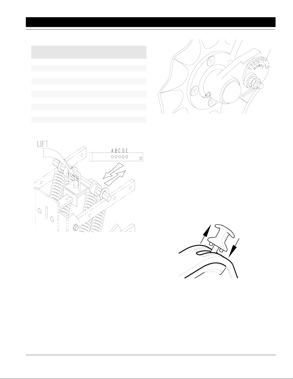
Spring Adjustments
• All spring adjustments must be made with the planter
in the fully raised position.
NOTE: The maximum down force stated before is
reached when the parallel arms are all the way up.
• The spring package is adjustable from 90 lbs. to 325
lbs. of down force when the parallel arms are horizontal. Consult the Down Force Pressure Chart on
page 11 to obtain the desired down force.
NOTE: To adjust the spring tension, lift the plunger by
pulling up on the roll pin handle and sliding the handle
adjustment assembly into the appropriate hole, see
Figure 3-8.
• Two springs can be purchased at your Great Plains
Dealer to make the medium duty package into a heavy
duty package or two springs can be removed from the
heavy duty package to make a medium duty package.
Add or subtract springs by removing the cotter key at
the end of the spring pivot rod. Slide the rod inward to
add or remove a spring from each side. Then attach or
remove the other spring end on the hex bar support.
Reinstall the spring rod and snap ring on each side.
Horizontal Alignment
Figure 3-7
12396
10
60303P and 80303P Three-Point Planter 401-008M 5/15/06
Great Plains Mfg., Inc.
Page 13
Section 3 Row Unit Operation
Down Force Pressure Chart
To Obtain This
* Down Force
90 lbs. 2 A
105 lbs. 2 B
125 lbs. 2 C
140 lbs. 2 D
160 lbs. 2 E
185 lbs. 4 A
215 lbs. 4 B
245 lbs. 4 C
285 lbs. 4 D
325 lbs. 4 E
* Force when arms are parallel.
Use This # of
Springs
In This
Hole
12208
Row Unit Mounted Coulter
Figure 3-9
Depth Adjustment
The planting depth of the row unit is controlled by 2 walking gauge tires located next to the disks.
Adjust the planting depth as follows:
1. Raise the planter to remove weight from the gauge
tires.
2. Raise the T-handle and move it forward to decrease
the planting depth, see Figure 3-10. Moving the handle rearward increases the planting depth. Small increments of depth adjustment can be made by
walking the T-handle from side to side.
3. After one row is set to the desired depth, move the
T-handle on the other rows to the same location.
12137
Adjustment Bar
Figure 3-8
Row Unit Mounted Coulter
The optional coulter allows the planter to penetrate
tough ground conditions. It is recommended that either
the medium duty or heavy duty spring package be used
in conjuction with this coulter.
Coulter Adjustments
1. To adjust the coulter vertically, loosen the 3/4" jam
nut and the 3/4" x 3" long hex bolt, see Figure 3-9.
2. By turning the cam hex, rotate the cam casting to set
the desired height. For wavy coulter blades, it is recommended that the coulter blade should be run
even to 1" below the disks on the row unit.
3. Tighten the bolt and jam nut to torque values in the
Torque Value Chart in "Section 9 Specifications"
on page 33.
5/15/06 Great Plains Mfg., Inc.
12345
T-Handle Adjustment
Figure 3-10
1 x 12 Closing Wheel Adjustments
The 1 X 12 closing wheel option can be adjusted for
down force, alignment, and offset.
Closing Wheel Down Force Adjustment
Adjust the closing wheel down force to permit proper
closing of the seed trench. It is recommended tostart with
the T-handle in the first of 4 notches, see Figure 3-11.
60303P and 80303P Three-Point Planter 401-008M
-11
Page 14

Section 3 Row Unit Operation
If the seed trench is not closing move the handle to the
next notch back and try again. Keep moving the handle
back until the seed trench is closing, by doing this eliminates unnecessary down force and compaction. In
some field conditions, the T-handle can be left in the forward slot to minimize down force.
Closing Wheel Adjuster
Figure 3-11
12346
Closing Wheel Alignment (Refer to Figure 3-12)
If one closing wheel is running in the seed trench or the
wheels are not centered over the seed trench, adjust the
closing wheels as follows:
1. Raise the planter slightly to remove weight from the
closing wheels.
2. Loosen the two 1/2" bolts.
3. Turn the press wheel adjuster left or right to center
the wheels over the seed trench.
4. Tighten the 1/2" bolts to the correct torque value listed in theTorque Values Chart in "Section 9 Speci-
fications" on page 33.
from plugging the closing wheels. If the closing wheels
are not offset, the wheels should be located in the front
holes of the press wheel arm.
To offset the wheels, do as follows:
1. Raise planter slightly to remove weight on the closing wheels.
2. Remove the 3/4” bolt holding the wheel,
see Figure 3-13.
3. Move the wheel to the rear hole and attach with the
3/4" bolt. Tighten the bolt to the correct torque value
listed in theTorque Values Chart in "Section 9
Specifications" on page 33.
12347
Closing Wheel & Offset
Figure 3-13
Closing Disk Adjustments
The closing disk options consists of two disks and a
6 1/2 x 12 press wheel. The disk down pressure can be
adjusted to provide closing of the seed trench.
To adjust the down pressure, ratchet the spring cam to
the next cam height by turning the head of the support
bolt clockwise. Refer to Figure 3-14.
12418
Closing Wheel Alignment
Closing Wheel Offset
Figure 3-12
Closing disk & Tube Holes
Figure 3-14
14913
The 1x12 wheels can be offset to help prevent trash
12
60303P and 80303P Three-Point Planter 401-008M 5/15/06
Great Plains Mfg., Inc.
Page 15

Section 3 Row Unit Operation
Seed Lok
The seed lok option provides additional seed to soil contact. The seed lok is spring loaded and does not require
adjusting. In some wet and sticky conditions the wheel
may accumulate soil and may require removal of the
seed lok until conditions improve.
The seed lok is attached to the shank with a 1/2" clevis pin, see
Figure 3-15. To remove the seed lok, remove the clevis pin and
pull down on the seed lok mount. Reattach in the reverse order.
12362
Seed Lok Assembly
Figure 3-15
5/15/06 Great Plains Mfg., Inc.
60303P and 80303P Three-Point Planter 401-008M
-13
Page 16
Section 4 Adjusting Planting Rates
Section 4 Adjusting Planting Rates
This section discusses the adjustments and settings for
seeding and chemical rates.
Planting Rates
Please read the following sections. Complete understanding of this process will help to prevent problems.
Transmission Adjustment
Planting population changes are accomplished by setting the sprocket transmission. By changing the
combination of sprockets the desired planting populations can be achieved.
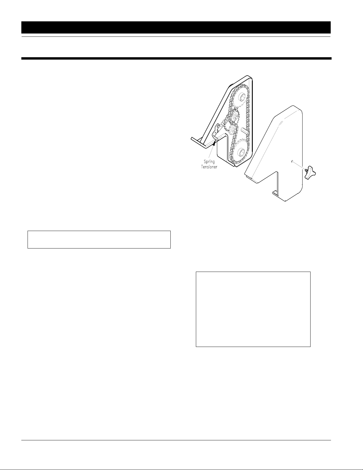
To change the sprocket combination, do as follows:
1. Select the sprocket combination for your planting population from the" Planting Rates for Finger Pickup
Corn Meter Chart" in this section on page 21.
2. Remove the cover from the transmission by loosening the knob on the cover.
3. Release the spring tensioner on the idler,
see Figure 4-1.
4. Remove the chain and sprockets.
5. Exchange the sprockets with the desired sprockets,
selected in step 1, on the storage bracket.
Note: When not in use, keep all extra sprockets on the
storage bracket.
6. Place the sprockets on the drive/driven shafts according to the " Planting Rates for Finger Pickup
Corn Meter Chart" in this section on page 21.
7. Loop the chain over the sprockets and between the
2 idlers.
8. Turn the idler counter-clockwise (ccw) to take up the
slack. Just before the idler sprocket reaches its limit
place the head of the sleeve lever mount in between
the two most vertical teeth of the idler sprocket. Rotate the spring tensioner lever over-center to apply
spring tension to hold the idler tight.
9. Replace the transmission cover and hand tighten
the knob.
Checking Planting Population
After setting the transmission, ALWAYS check the planting population in the field.
Follow these steps to check the planting population:
1. Tie up 1 or more closing disks and wheels with a
chain or heavy wire to the hopper support. Releasing the spring pressure on the disks and wheels will
make this easier. Adjust the planting depth to a shallow setting. It may be necessary to tie up the seed
lok wheels so that the seeds are easier to find.
2. Plant at a normal speed for a short distance.
12349
Spring Tensioner on Transmission
Figure 4-1
3. Measure 1/1000 of an acre. For 30" row planter
1/1000 of and acre is 17' 6".
4. Multiply the number of seeds counted by 1000. This
gives you total population.
Example: (for one row)
• 30" row spacing
• 17' 6" of seed trench measured off
• 24 seeds counted in measured
distance
24 Seeds Counted X 1000 =
24,000 Plant Population Per Acre
If the planting population is significantly different than
the desired planting population, make the following
checks:
• Check the sprocket combination in the transmission,
refer to the " Planting Rates for Finger Pickup Corn
Meter Chart" in this section on page 21.
• Check the tire pressure in the gauge wheels, see Spec-
ification in " Section 9 Specifications" on page 33.
• Check for meter malfunction, see Finger Pickup Corn
14
60303P and 80303P Three-Point Planter 401-008M 5/15/06
Great Plains Mfg., Inc.
Page 17

Section 4 Adjusting Planting Rates
Meter in "Section 5 Troubleshooting" on page 23.
Planting recommendations
To get the best planting results, follow these
recommendations:
• Plant at 5 mph
• Add 1 teaspoon of graphite to each seed hopper.
• Maintain tire pressure in the gauge tires.
• Replace worn meter parts.
Adjusting Granular Chemical Rates
The optional chemical applicators are adjusted by
varying the opening on the chemical meter housing. The
field check is very important because temperature, humidity, speed, ground conditions, flow ability of
chemicals, and obstructions affect the application rate.
!
Agricultural chemicals can be dangerous if not selected and
handled with care. Always read and follow directions supplied by the chemical manufacturer.
To adjust the chemical rate do as follows:
1. Select a setting from the "Granular Chemical Rate
2. Slide the handle on the meter to the setting,
3. If the meter has a knob, turn until the display shows
4. Fill the hoppers with chemical.
WARNING!
Chart" on pages 16 through 24, as a starting point.
see Figure 4-2 and Granular Chemical Rate Chart
on pages 23 and 24.
the appropriate number, see Figure 4-2 and Granular Chemical Rate Chart on pages 16 through 20.
5. Attach a plastic bag to each chemical
diffuser.
6. Drive 1320’ at a normal planting speed.
7. Weigh the contents of the bag in ounces.
8. Multiply ounces by.83 to determine the pounds
per acre.
9. If required, adjust the meter setting and repeat steps
4 through 7 until the desired rate is reached.
Chemical Meter
Figure 4-2
12350
5/15/06 Great Plains Mfg., Inc.
Chemical Meter
Figure 4-3
60303P and 80303P Three-Point Planter 401-008M
14914
-15
Page 18

Section 4 Adjusting Planting Rates
Insecticide Application Rates
Clay Agrisorb 30/60 Chemical Rate Chart
Approximate Rate in Lbs/Acre
30 Inch Rows 36 Inch Rows 38 Inch Rows Ounces per 1000 Row Ft.
Meter
Setting
10 0.9 0.6 0.5 1.1 0.8 0.6 1.2 0.8 0.6 0.87 0.58 0.43
11 1.1 0.7 0.6 1.3 0.9 0.7 1.4 0.9 0.7 1.03 0.69 0.51
12 1.3 0.9 0.7 1.6 1.1 0.8 1.7 1.1 0.8 1.22 0.82 0.61
13 1.6 1.1 0.8 1.9 1.3 0.9 2.0 1.3 1.0 1.45 0.97 0.72
14 1.9 1.2 0.9 2.2 1.5 1.1 2.3 1.6 1.2 1.70 1.13 0.85
15 2.1 1.4 1.1 2.6 1.7 1.3 2.7 1.8 1.4 1.97 1.32 0.99
16 2.5 1.6 1.2 3.0 2.0 1.5 3.1 2.1 1.6 2.27 1.51 1.14
17 2.8 1.9 1.4 3.4 2.3 1.7 3.6 2.4 1.8 2.59 1.72 1.29
18 3.2 2.1 1.6 3.8 2.5 1.9 4.0 2.7 2.0 2.92 1.94 1.46
19 3.6 2.4 1.8 4.3 2.8 2.1 4.5 3.0 2.2 3.26 2.17 1.63
20 3.9 2.6 2.0 4.7 3.2 2.4 5.0 3.3 2.5 3.62 2.41 1.81
21 4.3 2.9 2.2 5.2 3.5 2.6 5.5 3.7 2.7 3.99 2.66 1.99
22 4.8 3.2 2.4 5.7 3.8 2.9 6.0 4.0 3.0 4.37 2.91 2.18
23 5.2 3.4 2.6 6.2 4.1 3.1 6.5 4.4 3.3 4.75 3.17 2.37
24 5.6 3.7 2.8 6.7 4.5 3.4 7.1 4.7 3.5 5.14 3.43 2.57
25 6.0 4.0 3.0 7.2 4.8 3.6 7.6 5.1 3.8 5.53 3.69 2.77
26 6.5 4.3 3.2 7.7 5.2 3.9 8.2 5.4 4.1 5.93 3.95 2.96
27 6.9 4.6 3.4 8.3 5.5 4.1 8.7 5.8 4.4 6.33 4.22 3.16
28 7.3 4.9 3.7 8.8 5.9 4.4 9.3 6.2 4.6 6.72 4.48 3.36
29 7.8 5.2 3.9 9.3 6.2 4.7 9.8 6.5 4.9 7.12 4.75 3.56
30 8.2 5.5 4.1 9.8 6.6 4.9 10.4 6.9 5.2 7.52 5.01 3.76
31 8.6 5.7 4.3 10.3 6.9 5.2 10.9 7.3 5.5 7.92 5.28 3.96
32 9.1 6.0 4.5 10.9 7.2 5.4 11.5 7.6 5.7 8.31 5.54 4.16
33 9.5 6.3 4.7 11.4 7.6 5.7 12.0 8.0 6.0 8.71 5.80 4.35
34 9.9 6.6 5.0 11.9 7.9 5.9 12.5 8.4 6.3 9.10 6.06 4.55
35 10.3 6.9 5.2 12.4 8.3 6.2 13.1 8.7 6.5 9.48 6.32 4.74
36 10.7 7.2 5.4 12.9 8.6 6.4 13.6 9.1 6.8 9.87 6.58 4.93
37 11.2 7.4 5.6 13.4 8.9 6.7 14.1 9.4 7.1 10.25 6.83 5.12
38 11.6 7.7 5.8 13.9 9.3 6.9 14.6 9.8 7.3 10.62 7.08 5.31
39 12.0 8.0 6.0 14.4 9.6 7.2 15.2 10.1 7.6 11.00 7.33 5.50
40 12.4 8.3 6.2 14.9 9.9 7.4 15.7 10.5 7.8 11.37 7.58 5.69
41 12.8 8.5 6.4 15.3 10.2 7.7 16.2 10.8 8.1 11.74 7.83 5.87
42 13.2 8.8 6.6 15.8 10.5 7.9 16.7 11.1 8.3 12.11 8.07 6.05
43 13.6 9.1 6.8 16.3 10.9 8.2 17.2 11.5 8.6 12.47 8.32 6.24
44 14.0 9.3 7.0 16.8 11.2 8.4 17.7 11.8 8.8 12.84 8.56 6.42
45 14.4 9.6 7.2 17.2 11.5 8.6 18.2 12.1 9.1 13.20 8.80 6.60
46 14.8 9.8 7.4 17.7 11.8 8.9 18.7 12.5 9.3 13.56 9.04 6.78
47 15.2 10.1 7.6 18.2 12.1 9.1 19.2 12.8 9.6 13.92 9.28 6.96
48 15.6 10.4 7.8 18.7 12.4 9.3 19.7 13.1 9.8 14.28 9.52 7.14
49 16.0 10.6 8.0 19.1 12.8 9.6 20.2 13.5 10.1 14.65 9.76 7.32
50 16.3 10.9 8.2 19.6 13.1 9.8 20.7 13.8 10.3 15.01 10.01 7.51
51 16.7 11.2 8.4 20.1 13.4 10.0 21.2 14.1 10.6 15.38 10.25 7.69
52 17.2 11.4 8.6 20.6 13.7 10.3 21.7 14.5 10.9 15.75 10.50 7.87
53 17.6 11.7 8.8 21.1 14.0 10.5 22.2 14.8 11.1 16.12 10.75 8.06
54 18.0 12.0 9.0 21.6 14.4 10.8 22.8 15.2 11.4 16.50 11.00 8.25
55 18.4 12.3 9.2 22.1 14.7 11.0 23.3 15.5 11.6 16.88 11.26 8.44
56 18.8 12.5 9.4 22.6 15.0 11.3 23.8 15.9 11.9 17.27 11.52 8.64
57 19.2 12.8 9.6 23.1 15.4 11.5 24.4 16.2 12.2 17.67 11.78 8.83
58 19.7 13.1 9.8 23.6 15.7 11.8 24.9 16.6 12.5 18.07 12.05 9.04
59 20.1 13.4 10.1 24.2 16.1 12.1 25.5 17.0 12.7 18.48 12.32 9.24
miles per hour miles per hour miles per hour miles per hour
4 6 84684 6 8468
16
60303P and 80303P Three-Point Planter 401-008M 5/15/06
Great Plains Mfg., Inc.
Page 19

Section 4 Adjusting Planting Rates
Clay Agrisorb 30/60 Chemical Rate Chart (Continued)
Approximate Rate in Lbs/Acre
30 Inch Rows 36 Inch Rows 38 Inch Rows Ounces per 1000 Row Ft.
Meter
Setting
60 20.6 13.7 10.3 24.7 16.5 12.4 26.1 17.4 13.0 18.90 12.60 9.45
61 21.1 14.0 10.5 25.3 16.8 12.6 26.7 17.8 13.3 19.33 12.89 9.67
62 21.5 14.4 10.8 25.8 17.2 12.9 27.3 18.2 13.6 19.77 13.18 9.89
63 22.0 14.7 11.0 26.4 17.6 13.2 27.9 18.6 13.9 20.22 13.48 10.11
64 22.5 15.0 11.3 27.0 18.0 13.5 28.5 19.0 14.3 20.68 13.79 10.34
65 23.0 15.4 11.5 27.6 18.4 13.8 29.2 19.4 14.6 21.16 14.10 10.58
66 23.6 15.7 11.8 28.3 18.9 14.1 29.8 19.9 14.9 21.64 14.43 10.82
67 24.1 16.1 12.1 28.9 19.3 14.5 30.5 20.3 15.3 22.14 14.76 11.07
68 24.7 16.4 12.3 29.6 19.7 14.8 31.2 20.8 15.6 22.65 15.10 11.33
69 25.2 16.8 12.6 30.3 20.2 15.1 32.0 21.3 16.0 23.18 15.45 11.59
70 25.8 17.2 12.9 31.0 20.7 15.5 32.7 21.8 16.3 23.72 15.81 11.86
71 26.4 17.6 13.2 31.7 21.1 15.9 33.5 22.3 16.7 24.27 16.18 12.13
72 27.0 18.0 13.5 32.5 21.6 16.2 34.2 22.8 17.1 24.84 16.56 12.42
73 27.7 18.5 13.8 33.2 22.1 16.6 35.0 23.4 17.5 25.42 16.95 12.71
74 28.3 18.9 14.2 34.0 22.7 17.0 35.9 23.9 17.9 26.02 17.34 13.01
75 29.0 19.3 14.5 34.8 23.2 17.4 36.7 24.5 18.4 26.63 17.75 13.31
76 29.7 19.8 14.8 35.6 23.7 17.8 37.6 25.1 18.8 27.25 18.17 13.63
77 30.4 20.3 15.2 36.5 24.3 18.2 38.5 25.6 19.2 27.90 18.60 13.95
78 31.1 20.7 15.5 37.3 24.9 18.7 39.4 26.2 19.7 28.55 19.03 14.28
79 31.8 21.2 15.9 38.2 25.5 19.1 40.3 26.9 20.1 29.22 19.48 14.61
80 32.6 21.7 16.3 39.1 26.1 19.5 41.2 27.5 20.6 29.90 19.94 14.95
81 33.3 22.2 16.7 40.0 26.7 20.0 42.2 28.1 21.1 30.60 20.40 15.30
82 34.1 22.7 17.0 40.9 27.3 20.5 43.2 28.8 21.6 31.31 20.87 15.65
83 34.9 23.3 17.4 41.9 27.9 20.9 44.2 29.4 22.1 32.03 21.35 16.01
84 35.7 23.8 17.8 42.8 28.5 21.4 45.2 30.1 22.6 32.76 21.84 16.38
85 36.5 24.3 18.2 43.8 29.2 21.9 46.2 30.8 23.1 33.50 22.33 16.75
86 37.3 24.9 18.6 44.8 29.8 22.4 47.2 31.5 23.6 34.25 22.83 17.12
87 38.1 25.4 19.1 45.7 30.5 22.9 48.3 32.2 24.1 35.00 23.33 17.50
88 38.9 26.0 19.5 46.7 31.2 23.4 49.3 32.9 24.7 35.76 23.84 17.88
89 39.8 26.5 19.9 47.7 31.8 23.9 50.4 33.6 25.2 36.53 24.35 18.27
90 40.6 27.1 20.3 48.7 32.5 24.4 51.4 34.3 25.7 37.30 24.87 18.65
miles per hour miles per hour miles per hour miles per hour
4 6 84684 6 8468
5/15/06 Great Plains Mfg., Inc.
60303P and 80303P Three-Point Planter 401-008M
-17
Page 20

Section 4 Adjusting Planting Rates
Insecticide Application Rates
Sand Granules Chemical Rate Chart
Approximate Rate in Lbs/Acre
30 Inch Rows 36 Inch Rows 38 Inch Rows Ounces per 1000 Row Ft.
Meter
Setting
5 1.7 1.1 0.8 2.0 1.3 1.0 2.1 1.4 1.1 1.53 1.02 0.76
6 2.2 1.4 1.1 2.6 1.7 1.3 2.7 1.8 1.4 1.98 1.32 0.99
7 2.7 1.8 1.3 3.2 2.2 1.6 3.4 2.3 1.7 2.47 1.65 1.23
8 3.3 2.2 1.6 3.9 2.6 2.0 4.1 2.8 2.1 3.00 2.00 1.50
9 3.9 2.6 1.9 4.7 3.1 2.3 4.9 3.3 2.5 3.56 2.38 1.78
10 4.5 3.0 2.3 5.4 3.6 2.7 5.7 3.8 2.9 4.17 2.78 2.08
11 5.2 3.5 2.6 6.3 4.2 3.1 6.6 4.4 3.3 4.82 3.21 2.41
12 6.0 4.0 3.0 7.2 4.8 3.6 7.6 5.1 3.8 5.50 3.67 2.75
13 6.8 4.5 3.4 8.1 5.4 4.1 8.6 5.7 4.3 6.23 4.15 3.12
14 7.6 5.1 3.8 9.1 6.1 4.6 9.6 6.4 4.8 7.00 4.66 3.50
15 8.5 5.7 4.2 10.2 6.8 5.1 10.8 7.2 5.4 7.80 5.20 3.90
16 9.4 6.3 4.7 11.3 7.5 5.7 11.9 7.9 6.0 8.65 5.77 4.32
17 10.4 6.9 5.2 12.5 8.3 6.2 13.1 8.8 6.6 9.53 6.35 4.77
18 11.4 7.6 5.7 13.7 9.1 6.8 14.4 9.6 7.2 10.45 6.97 5.23
19 12.4 8.3 6.2 14.9 9.9 7.5 15.7 10.5 7.9 11.41 7.60 5.70
20 13.5 9.0 6.7 16.2 10.8 8.1 17.1 11.4 8.5 12.39 8.26 6.20
21 14.6 9.7 7.3 17.5 11.7 8.8 18.5 12.3 9.2 13.41 8.94 6.71
22 15.8 10.5 7.9 18.9 12.6 9.5 19.9 13.3 10.0 14.47 9.64 7.23
23 16.9 11.3 8.5 20.3 13.5 10.2 21.4 14.3 10.7 15.55 10.36 7.77
24 18.1 12.1 9.1 21.8 14.5 10.9 23.0 15.3 11.5 16.65 11.10 8.33
25 19.4 12.9 9.7 23.2 15.5 11.6 24.5 16.3 12.3 17.78 11.86 8.89
26 20.6 13.7 10.3 24.7 16.5 12.4 26.1 17.4 13.1 18.94 12.62 9.47
27 21.9 14.6 11.0 26.3 17.5 13.1 27.7 18.5 13.9 20.11 13.41 10.06
28 23.2 15.5 11.6 27.8 18.6 13.9 29.4 19.6 14.7 21.30 14.20 10.65
29 24.5 16.3 12.3 29.4 19.6 14.7 31.0 20.7 15.5 22.51 15.01 11.26
30 25.8 17.2 12.9 31.0 20.7 15.5 32.7 21.8 16.4 23.73 15.82 11.87
31 27.2 18.1 13.6 32.6 21.7 16.3 34.4 22.9 17.2 24.97 16.64 12.48
32 28.5 19.0 14.3 34.2 22.8 17.1 36.1 24.1 18.1 26.21 17.47 13.10
33 29.9 19.9 14.9 35.9 23.9 17.9 37.8 25.2 18.9 27.45 18.30 13.73
34 31.3 20.8 15.6 37.5 25.0 18.8 39.6 26.4 19.8 28.71 19.14 14.35
35 32.6 21.8 16.3 39.2 26.1 19.6 41.3 27.5 20.7 29.96 19.97 14.98
36 34.0 22.7 17.0 40.8 27.2 20.4 43.0 28.7 21.5 31.21 20.81 15.61
37 35.4 23.6 17.7 42.4 28.3 21.2 44.8 29.8 22.4 32.46 21.64 16.23
38 36.7 24.5 18.4 44.0 29.4 22.0 46.5 31.0 23.2 33.71 22.47 16.85
39 38.1 25.4 19.0 45.7 30.4 22.8 48.2 32.1 24.1 34.95 23.30 17.47
40 39.4 26.3 19.7 47.3 31.5 23.6 49.9 33.2 24.9 36.17 24.12 18.09
41 40.7 27.1 20.4 48.9 32.6 24.4 51.6 34.4 25.8 37.39 24.93 18.70
42 42.0 28.0 21.0 50.4 33.6 25.2 53.2 35.5 26.6 38.60 25.73 19.30
43 43.3 28.9 21.7 52.0 34.7 26.0 54.9 36.6 27.4 39.79 26.53 19.90
44 44.6 29.7 22.3 53.5 35.7 26.8 56.5 37.7 28.2 40.97 27.31 20.48
45 45.9 30.6 22.9 55.1 36.7 27.5 58.1 38.7 29.0 42.13 28.08 21.06
46 47.1 31.4 23.6 56.5 37.7 28.3 59.7 39.8 29.8 43.27 28.85 21.63
47 48.3 32.2 24.2 58.0 38.7 29.0 61.2 40.8 30.6 44.39 29.59 22.20
48 49.5 33.0 24.8 59.5 39.6 29.7 62.7 41.8 31.4 45.49 30.33 22.75
49 50.7 33.8 25.4 60.9 40.6 30.4 64.2 42.8 32.1 46.58 31.05 23.29
50 51.9 34.6 25.9 62.3 41.5 31.1 65.7 43.8 32.8 47.64 31.76 23.82
51 53.0 35.3 26.5 63.6 42.4 31.8 67.1 44.7 33.6 48.68 32.45 24.34
52 54.1 36.1 27.1 64.9 43.3 32.5 68.5 45.7 34.3 49.70 33.13 24.85
53 55.2 36.8 27.6 66.2 44.2 33.1 69.9 46.6 34.9 50.70 33.80 25.35
54 56.3 37.5 28.1 67.5 45.0 33.8 71.2 47.5 35.6 51.68 34.45 25.84
miles per hour miles per hour miles per hour miles per hour
4 6 84684 6 8468
18
60303P and 80303P Three-Point Planter 401-008M 5/15/06
Great Plains Mfg., Inc.
Page 21

Section 4 Adjusting Planting Rates
Sand Granules Chemical Rate Chart (Continued)
Approximate Rate in Lbs/Acre
30 Inch Rows 36 Inch Rows 38 Inch Rows Ounces per 1000 Row Ft.
Meter
Setting
55 57.3 38.2 28.7 68.8 45.9 34.4 72.6 48.4 36.3 52.64 35.09 26.32
56 58.3 38.9 29.2 70.0 46.7 35.0 73.9 49.2 36.9 53.58 35.72 26.79
57 59.4 39.6 29.7 71.2 47.5 35.6 75.1 50.1 37.6 54.50 36.34 27.25
58 60.3 40.2 30.2 72.4 48.3 36.2 76.4 50.9 38.2 55.42 36.94 27.71
59 61.3 40.9 30.7 73.6 49.1 36.8 77.6 51.8 38.8 56.32 37.54 28.16
60 62.3 41.5 31.1 74.8 49.8 37.4 78.9 52.6 39.4 57.21 38.14 28.60
61 63.3 42.2 31.6 75.9 50.6 38.0 80.1 53.4 40.0 58.09 38.73 29.05
62 64.2 42.8 32.1 77.1 51.4 38.5 81.3 54.2 40.6 58.97 39.31 29.48
63 65.2 43.5 32.6 78.2 52.1 39.1 82.5 55.0 41.3 59.85 39.90 29.92
64 66.1 44.1 33.1 79.4 52.9 39.7 83.7 55.8 41.9 60.73 40.49 30.37
65 67.1 44.7 33.6 80.5 53.7 40.3 85.0 56.6 42.5 61.62 41.08 30.81
67 69.1 46.1 34.5 82.9 55.3 41.5 87.5 58.3 43.7 63.45 42.30 31.73
68 70.1 46.8 35.1 84.2 56.1 42.1 88.8 59.2 44.4 64.40 42.93 32.20
69 71.2 47.5 35.6 85.4 57.0 42.7 90.1 60.1 45.1 65.38 43.58 32.69
70 72.3 48.2 36.2 86.8 57.8 43.4 91.5 61.0 45.8 66.39 44.26 33.20
71 73.5 49.0 36.7 88.1 58.8 44.1 93.0 62.0 46.5 67.45 44.97 33.72
72 74.7 49.8 37.3 89.6 59.7 44.8 94.5 63.0 47.3 68.56 45.71 34.28
73 75.9 50.6 38.0 91.1 60.7 45.6 96.1 64.1 48.1 69.73 46.49 34.86
74 77.3 51.5 38.6 92.7 61.8 46.4 97.8 65.2 48.9 70.96 47.31 35.48
75 78.7 52.5 39.4 94.5 63.0 47.2 99.6 66.4 49.8 72.28 48.19 36.14
76 80.2 53.5 40.1 96.3 64.2 48.1 101.6 67.7 50.8 73.68 49.12 36.84
77 81.9 54.6 40.9 98.2 65.5 49.1 103.6 69.1 51.8 75.18 50.12 37.59
78 83.6 55.7 41.8 100.3 66.9 50.2 105.9 70.6 52.9 76.78 51.19 38.39
79 85.5 57.0 42.7 102.6 68.4 51.3 108.2 72.2 54.1 78.51 52.34 39.25
80 87.5 58.3 43.8 105.0 70.0 52.5 110.8 73.9 55.4 80.36 53.58 40.18
81 89.7 59.8 44.8 107.6 71.8 53.8 113.6 75.7 56.8 82.36 54.91 41.18
82 92.0 61.4 46.0 110.4 73.6 55.2 116.5 77.7 58.3 84.52 56.35 42.26
83 94.6 63.1 47.3 113.5 75.7 56.7 119.7 79.8 59.9 86.85 57.90 43.42
84 97.3 64.9 48.7 116.8 77.8 58.4 123.2 82.1 61.6 89.36 59.57 44.68
85 100.3 66.8 50.1 120.3 80.2 60.2 126.9 84.6 63.5 92.07 61.38 46.03
miles per hour miles per hour miles per hour miles per hour
4 6 84684 6 8468
5/15/06 Great Plains Mfg., Inc.
60303P and 80303P Three-Point Planter 401-008M
-19
Page 22

Section 4 Adjusting Planting Rates
Liquid Fertilizer Rate Chart
Transmission
Combination
Driver Driven Gallons/Acre Gallons/Acre
15 44 3.49 8.99
15 41 3.75 9.65
17 44 4.06 10.19
17 41 4.25 10.94
19 44 4.43 11.39
15 32 4.8 12.36
21 41 5.25 13.51
17 32 5.45 14.01
24 41 6.00 15.44
19 32 6.09 15.66
15 24 6.41 16.48
17 24 7.26 18.68
15 21 7.32 18.84
17 23 7.58 19.49
15 19 8.09 20.82
17 21 8.30 21.35
19 23 8.47 21.79
15 17 9.04 23.27
17 19 9.17 23.60
23 24 9.82 25.28
24 23 10.70 27.52
19 17 11.46 29.48
17 15 11.62 29.89
23 19 12.41 31.93
21 17 12.66 32.58
19 15 12.98 33.41
23 17 13.87 35.68
21 15 14.35 36.93
24 17 14.47 37.24
32 21 15.62 40.19
24 15 16.40 42.20
32 19 17.26 44.42
41 24 17.51 45.06
32 17 19.29 49.65
41 21 20.01 51.49
32 15 21.87 56.27
44 19 23.74 61.08
41 17 24.72 63.61
44 17 26.53 68.26
41 15 28.02 72.09
44 15 30.07 77.37
Hose Dia. at 5/16 Hose Dia. at 1/2
NOTE: The delivery rates are approximate and will vary with changes in temperature and the specific fertilizer
being used.
20
60303P and 80303P Three-Point Planter 401-008M 5/15/06
Great Plains Mfg., Inc.
Page 23

Section 4 Adjusting Planting Rates
Planting Rates for Finger Pickup Corn Meters
Planting Rates 30" Row Width
Planting
Population/
Acre
24,849 17 19 4 to 7.5 8.4
25.550 23 25 4 to 7.5 8.2
25,636 24 26 4 to 7.5 8.2
25,715 25 27 4 to 7.5 8.1
25,788 26 28 4 to 7.5 8.1
26,615 23 24 4 to 7.5 7.9
26,661 24 25 4 to 7.5 7.8
26,704 25 26 4 to 7.5 7.8
26,743 26 27 4 to 7.5 7.8
26,780 27 28 4 to 7.5 7.8
27,772 23 23 4 to 7 7.5
28,800 28 27 4 to 7 7.3
28,840 27 26 4 to 7 7.3
28,929 25 24 4 to 7 7.2
28,979 24 23 4 to 7 7.2
29,908 28 26 4 to 6.5 7.0
29,994 27 25 4 to 6.5 7.0
30,187 25 23 4 to 6.5 6.9
31,039 19 17 4 to 6.5 6.7
31,103 28 25 4 to 6.5 6.7
31,243 27 24 4 to 6.5 6.7
31,394 26 23 4 to 6.5 6.7
32,401 28 24 3 to 6 6.5
32,602 27 23 3 to 6 6.4
33,619 23 19 3 to 5.5 6.2
33,809 28 23 3 to 5.5 6.2
35,080 24 19 3 to 5.5 6.0
36,542 25 19 3 to 5 5.7
37,574 23 17 3 to 5 5.6
38,004 26 19 3 to 5 5.5
39,207 24 17 3 to 5 5.3
39,465 27 19 3 to 5 5.3
40,841 25 17 3 to 4.5 5.1
40,927 28 19 3 to 4.5 5.1
42,475 26 17 3 to 4.5 4.9
44,108 27 17 3 to 4.5 4.7
45,742 28 17 3 to 4.5 4.6
Planting Rates 30" Row Width
Planting
Population/
Acre
16,862 17 28 4 to 8 12.4
17,486 17 27 4 to 8 12.0
18,159 17 26 4 to 8 11.5
18,845 19 28 4 to 8 11.1
18,885 17 25 4 to 8 11.1
19,543 19 27 4 to 8 10.7
19,672 17 24 4 to 8 10.6
20,295 19 26 4 to 8 10.3
20,527 17 23 4 to 8 10.2
21,107 19 25 4 to 8 9.9
21,986 19 24 4 to 8 9.5
22,813 23 28 4 to 8 9.2
22,942 19 23 4 to 8 9.1
23,658 23 27 4 to 8 8.8
23,805 24 28 4 to 8 8.8
24,568 23 26 4 to 8 8.5
24,686 24 27 4 to 8 8.5
24,796 25 28 4 to 8 8.4
Transmission
Sprockets
Drive Driven
Recommended
Speed Range
(mph)
Average Seed
12548
Spacing
(inches)
IMPORTANT: See “Planting Rates” and “Checking Planting Population”, on page 14 for additional information. Always check seed population in the field to ensure planting rates are correct.
Transmission
Sprockets
Drive Driven
Recommended
Speed Range
(mph)
Average Seed
Spacing
(inches)
5/15/06 Great Plains Mfg., Inc.
60303P and 80303P Three-Point Planter 401-008M
-21
Page 24

Section 4 Adjusting Planting Rates
Granular Chemical Rate Charts
Dry Insecticide Application Rates
Approximate Pounds/Acre at 5 mph
for a 30” Row Spacing
Meter Setting Clay Granules Sand Granules
5 --- 3.0
6 --- 5.0
7 --- 5.5
8 --- 6.5
9 --- 8.0
10 5.1 9.2
11 5.6 10.5
12 6.3 11.5
13 7.1 13.0
14 7.9 14.5
15 8.8 16.0
16 9.9 18.0
17 11.0 20.0
Dry Herbicide Application Rates
Approximate Pounds/Acre at 5 mph
for a 30” Row Spacing
Meter Setting Clay Granules
10 4.8
11 5.4
12 6.0
13 6.7
14 7.5
15 7.1
16 9.3
17 10.2
18 11.0
19 12.0
20 13.0
21 14.0
22 15.0
18 11.8 22.5
19 13.5 25.0
20 14.6 26.5
21 16.0 28.5
22 16.9 30.5
23 17.7 33.0
24 19.4 35.5
25 21.5 38.0
26 23.7 ---
27 24.8 ---
28 26.2 ---
29 28.7 ---
30 30.5 ---
23 16.2
24 17.5
25 18.7
26 20.0
27 21.5
28 23.3
29 25.0
30 27.5
22
60303P and 80303P Three-Point Planter 401-008M 5/15/06
Great Plains Mfg., Inc.
Page 25

Section 5 Troubleshooting
Section 5 Troubleshooting
Finger Pickup Corn Meter
Problem Possible Cause Solution
One row not planting seed.
Drive release does not engage properly.
Unit is skipping.
Planting too many doubles.
Over planting.
Under planting.
Irregular or incorrect seed spacing.
Seed spacing not as indicated in
charts.
Scattering of seeds.
Seed tubes and/or openers plugging.
Inconsistent seed depth.
Drive clutch release not engaged. Engaged clutch release mechanism.
Foreign material in hopper. Clean hopper and finger carrier mechanism.
Seed hopper empty. Fill seed hopper.
Row unit drive chain off of sprocket or broken. Repair or replace drive chain.
Drive release shaft isn’t aligned properly with
meter drive shaft.
Foreign material or obstruction in meter. Clean out and inspect.
Finger holder improperly adjusted. Adjust to proper setting. (22 to 25 inch pounds
Broken fingers. Replace fingers and/or springs as required.
Planting too slowly. Increase planting speed to within recommended
Planting too fast. Stay within recommended range.
Lose finger holder. Adjust to specifications (22 to 24 inch pounds
Worn brush in carrier plate. Inspect and replace if necessary.
Worn carrier plate. Inspect and replace if necessary.
Belt installed backwards. Remove and install correctly.
Weak springs. Replace.
Spring not properly installed. Remove finger holder and correct.
Seed belt catching or dragging. Replace belt.
Brush dislodging seed. Replace brush.
Driving too fast. Check chart for correct speed.
Wrong tire pressure. Inflate tires to correct air pressure.
Drive wheels slipping. Reduce down pressure on row unit down force
Wrong sprockets. Check planting rate charts for correct sprocket
Wrong tire pressure. Inflate tires to correct air pressure.
Inconsistent seed size. Do field check and adjust sprockets accordingly.
Wrong sprockets. Check chart for correct sprocket combination.
Charts are approximate. Slight variations due to wear may produce seed
Planting too fast. Reduce planting speed.
Seed tube improperly installed. Check seed tube installation.
Seed tube worn or damaged. Replace seed tube.
Allowing planter to roll backward when lowering. Lower planter only when tractor is moving forward.
Rough seed bed. Adjust down pressure springs
Partially plugged seed tube. Inspect and clean.
Seed tube improperly installed. Install properly.
Align drive mechanism. See “Meter Drive
Adjustment”.
torque)
range.
torque)
springs.
combinations.
spacing variations.
5/15/06 Great Plains Mfg., Inc.
60303P and 80303P Three-Point Planter 401-008M
-23
Page 26
Section 6 Lubrication
Section 6 Lubrication
With proper lubrication and care of your planter you will
reduce costly repairs and extend the life of the planter.
Conditions in certain areas may require special lubricants. Contact your Great Plains Dealer if you have any
questions.
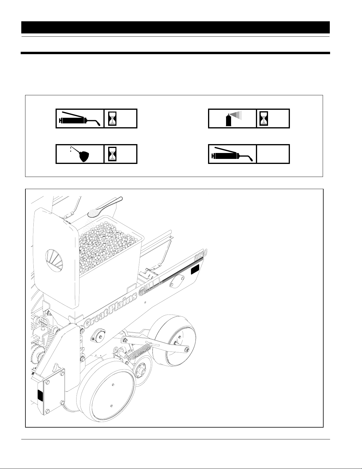
Lubrication Symbols
As
50
Lubrication is required every 50 hours of operation. Use a multipurpose spray lube. Use as required.
Do not over lubricate.
Required
10
Seasonally
Lubrication is required.Lubrication is required every 10 hours of operation.
Finger Pickup Meter
To prolong the life the finger pickup
meter and increase the planting accuracy, add a teaspoon of graphite to the
seeds every time you fill the hopper.
Sprinkle the graphite on top of the seeds
and it will filter down to lubricate the
finger pickup meter, see Figure 6-1.
Finger Pickup Meter Lubrication
Figure 6-1
12342
24
60303P and 80303P Three-Point Planter 401-008M 5/15/06
Great Plains Mfg., Inc.
Page 27

Section 6 Lubrication
12372
12351
Seasonally
Wheel Bearings
Pump grease into the hub until grease comes out
around the seals. Lift the wheel off the ground. Move the
tire in and out to check for end play. Check for roughness in the bearing by rotating the wheel. If the bearings
are rough they should be inspected and replaced if
necessary.
As
Required
Seed and Chemical Meter Chains
Lubricate all chains at intervals to maintain freedom at
every chain link joint. Use a multipurpose spray lubricant
on chains, because it penetrates into the rollers on the
chain. Spray chains if planter is going to be idle to prevent the chains from rusting and becoming stiff. Stiff
chains will cause metering inaccuracies.
10202
12352
As
Required
Gauge Wheel Chains
Lubricate all chains at intervals to maintain freedom at
every chain link joint. Use a multipurpose spray lubricant
on chains, because it penetrates into the rollers on the
chain. Spray chains if planter is going to be idle to prevent the chains from rusting and becoming stiff. Stiff
chains will cause metering inaccuracies.
50
Gauge Wheel Module
Lubricate gauge wheel module links every 50 hours.
5/15/06 Great Plains Mfg., Inc.
60303P and 80303P Three-Point Planter 401-008M
-25
Page 28
Section 7 Maintenance
Section 7 Maintenance
13337
50
Gauge Wheel Side Arm
3 to 4 pumps of grease into the zerk with universal allpurpose grease every 50 hours.
Proper maintenance can prevent unnecessary down
time and prolong the life of your planter.
Fasteners
When working on the planter torque all bolts, screws,
and nuts to the correct values listed in the Torque Values Chart in "Section 9 Specifications" on page 33.
Check latches and other fasteners on the planter to prevent failures in the field.
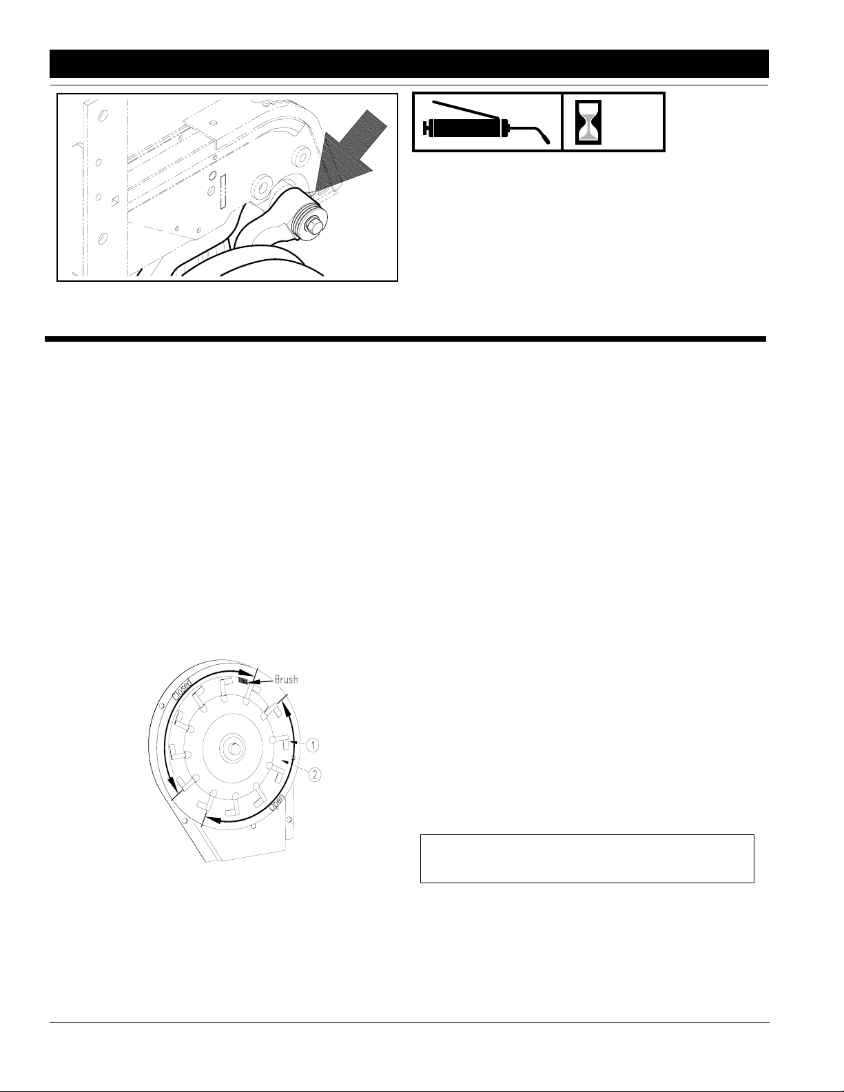
Finger Pickup Meter
Inspect and repair the finger pickup meter by removing
the 2 bolts holding the meter to the hopper. Remove the
3 bolts on the meter baffle to gain access to the finger
mechanism.
Rotate the meter input shaft by hand to check the fingers. The fingers should be against the carrier plate in
the area shown closed and raised in the area shown
open in Figure 7-1.
To clean the corn meter:
1. Remove the cotter pin, lock nut, and adjusting nut
from the shaft.
2. Lift the finger assembly off the shaft and clean.
3. Replace worn fingersand springs by lifting thefinger
out of the slot. Average life expectancy of these
parts should be 250-300 acres of row operation.
When fingers are replaced, the open end of the
spring loop should be toward the inside of the finger
housing.
4. Inspect the indentations in the carrier plate for wear.
Replace the carrier plate when wear to the plate becomes excessive or the seeding accuracy will be affected.
5. Reassemble the meter in reverse order. Be sure the
fingers are installed correctly so the finger housing
is flush with the carrier plate. If the finger housing is
not flush with the carrier plate, make sure that the
projection on the cam is in the notch on the bearing
housing. The meter will not function properly if the
projection is not in the notch.
6. With the finger assembly against the plate, tighten
the adjusting nut until it is snug. Then turn an additional 1/3 turn. Turn the meter by hand making certain that the meter is not over tightened. Proper
meter resistance would be 22-25 in/lbs of torque applied at the meter input shaft.
7. Install the cage nut and the cotter pin.
8. Install the baffle and attach the meter to the hopper.
12353
Finger Raised/Location of Brush
Figure 7-1
Inspect the brush for wear and replace every 100 acres
of row operation, see Figure 7-1 for location.
Chaf and debris can build-up in the meter preventing
proper functioning of the fingers.
26
60303P and 80303P Three-Point Planter 401-008M 5/15/06
Note: Check tightness of the adjusting nut on the
meter after the first day and periodically thereafter.
Check the belt on the meter periodically.
Use these steps:
1. Remove the 4 bolts located on the belt housing and
the bolt holding the belt roller.
2. Inspect or replace the seed belt.
3. Reassemble in the reverse order.
Great Plains Mfg., Inc.
Page 29

Section 7 Maintenance
Spreader and Scraper
The spreader and scraper between the disks will periodically need replacing. These components scrape dirt off
the disks and protect the seed tube.
To inspect or replace the spreader or scraper do as
follows:
1. Remove the side gauge wheel and the arm from the
row unit.
2. Remove the disk blade. Be careful, disks wear very
sharp!
3. Remove both of the 1/4" bolts holding the scraper
and spreader.
4. If the sides of the seed tube are worn, replace the
scraper and spreader.
5. Install the scraper and spreader with 1/4" bolts.
Torque the bolts to the correct values as listed in the
Torque Values Chart in "Section 9Specifications"
on page 33.
6. Install the disk and torque the bolt to the correct value as listed in Torque Values Chart in "Section 9
Specifications" on page 33.
7. Install the gauge wheel according to directions under the Gauge Wheels heading on page 27, below.
Disk
As the disks on the row unit wear, removal of shims may
be required to maintain contact point. To remove disk do
as follows:
!
CAUTION!
Disk blades wear very sharp. Handle with care.
1. Remove side gauge wheels and arm from the row unit.
2. Remove 3/4" bolts retaining the disks.
3. Measure disk diameter, if disk measures 14 1/2" or
less replace disk.
4. If contact is to be increase, move shims from behind
disk to outside disks. This will increase the contact
between the disks.
5. Install disks and tighten 3/4" bolts to torque values in
Specification Section.
6. Install gauge wheels and arms according to directions in this section.
Gauge Wheels
Periodically check gauge tires to be sure there is contact
or a 1/16" gap between the tires and disks.
For installation or adjustments proceed as follows:
1. Remove the 1/2" bolt holding arm on to the shank.
2. If the tire needs to be closer to the disk, move an appropriate amount of shims from the inside of the arm
to the outside, see Figure 7-2. Each shim is .050
thick.
12354
Gauge Arm, Spindle, and Shims
Figure 7-2
3. Install the arm and the shims onto the spindle. Tighten 1/2" bolt to the correct torque value as listed in
the Torque Values Chart in "Section 9 Specifica-
tions" on page 33.
4. Check clearance or contact of the tire and disk. The
gauge wheel should fall freely when lifted. Repeat
steps 1 through 4 if necessary.
Outside Scrapers
The row units are equipped with outside disk scrapers to
remove dirt from the disks.
Periodically check the scrapers as follows:
1. Remove the gauge tires to inspect the scrapers.
2. Make sure the scrapers are contacting the disk with
some pressure.
3. If scrapers are not contacting the disks properly,
bend and twist the scrapers as required to establish
contact. If the scraper is worn too much, replace it by
removing the two 1/4" bolts. Bolt the new scraper in
place and torque the bolts to correct values as listed
in the Torque Values Chart in "Section 9 Specifica-
tions" on page 33.
Shear Pins
The planter drive line and row units are protected by
shear pins on transmission upper and lower shafts..
Check and replace bent or broken pins as required.
Chain Tension
The planter is equipped with spring loaded idlers to
maintain tension in the chains. As the chains wear and
stretch, the link(s) may be removed to provide proper
chain length and tension. Check and replace broken
springs and bushings on idlers. Forthe correct operation
of the planter check all chain routings. Refer to page 28
for the chain routing diagrams.
5/15/06 Great Plains Mfg., Inc.
60303P and 80303P Three-Point Planter 401-008M
-27
Page 30

Section 7 Maintenance
Drive Gauge Wheel Chain Routing
10202
Meter Drive Chain Routing
12358
Counter Shaft Support Chain Routing
12355
12351
Granular Chemical Drive Chain Routing
28
60303P and 80303P Three-Point Planter 401-008M 5/15/06
12349
Transmission Chain Routing
Great Plains Mfg., Inc.
Page 31

Section 7 Maintenance
Maintenance & Lubrication Record
Item to be Serviced When to Perform Reference Date
5/15/06 Great Plains Mfg., Inc.
60303P and 80303P Three-Point Planter 401-008M
-29
Page 32

Section 8 Storage
Section 8 Storage
To extend the life of your planter follow the recommendations for removing the planter from storage and
storing the planter during the off season.
Beginning of the Season
Inspect the hoppers for debris and clean if necessary to
prevent damage to the meters.
Clean dirt and grease from the chains and moving parts.
This will prevent the abrasive action of dirt from causing
excessive wear to chains and other parts. Lubricate the
planter according to the directions in "Section 6 Lubri-
cation" on page 26.
Check all bolts and replace worn parts on the planter to
prevent failure in the field. Make adjustments to the
planter for the field conditions to be encountered.
Ending of the Season
When planting is complete clean the seed and chemical
hoppers. Remove all dirt, debris, chemicals, and fertilizer from the planter that may hold moisture and cause
corrosion.
Use spray paint to cover scratches, chips, and worn ar-
eas on the planter to protect the metal.
Lubricate the planter as outlined in "Section 6 Lubrica-
tion" on page 26. Pay careful attention to the lubrication
of the chains to help prevent rusting.
Inspect the planter for worn or damaged parts. Make repairs and service during the off season to reduce down
time in the field.
Place the 1 X 12 closing wheel handle in the middle slot
to relieve the tension on the closing wheels. Move opener adjustment bar on heavy and medium down pressure
spring packages to hole A.
Remove the finger pickup meters from the hoppers. Disassemble the meters and inspect them for wear. Make
any repairs required at this time. Blow excessive debris
from the meter. Wash the meters with mild soap and water. Dry the meters and spray a light coat of rust inhibitor
on the meters. Reassemble and store in a dry place.
Store the planter in a clean, dry place with all tires out of
the sun. A sheltering structure is best for overall protection, but a high quality tarp would suffice.
30
60303P and 80303P Three-Point Planter 401-008M 5/15/06
Great Plains Mfg., Inc.
Page 33

Section 9 Specifications
Section 9 Specifications
6 - Row 30"
Frame 7" sq. 5/16" Wall 7" sq. 5/16" Wall
9.5L X 15 Drive Gauge Wheels 2 2
Planter Width 16' 15’
Planter Height 5' 4’
Planter Length 6' 6’
Shipping Weight (empty) 2800 lbs. 2400 lbs. (approx.)
8 - Row 30"
Frame 7" sq. 3/8" Wall 7" sq. 3/8" Wall
9.5L X 15 Drive Gauge Wheels 2 2
Planter Width 21' 20’
Planter Height 5' 4’
Planter Length 6' 6’
Shipping Weight (empty) 3800 lbs. 3380 lbs. (approx.)
With Markers Without Markers
With Markers Without Markers
Row Unit Equipment
Standard
2 bu. Seed Hopper (Standard with corn Meter)
Double disk staggered Openers
4" x 16" Gauge tires
Light Down Pressure Springs
5/15/06 Great Plains Mfg., Inc.
Optional
80 lbs. Insecticide/Herbicide Hopper with
7" & 14" Diffusers
1 x 12 Double “V” Press Wheels
Closing Disc’s with 6 1/2" x 12" Press Wheel
Medium & Heavy Down Pressure Springs
Seed Lok
60303P and 80303P Three-Point Planter 401-008M
-31
Page 34

Section 9 Specifications
12445
Specification Diagram
Figure 9-1
32
60303P and 80303P Three-Point Planter 401-008M 5/15/06
Great Plains Mfg., Inc.
Page 35
Section 9 Specifications
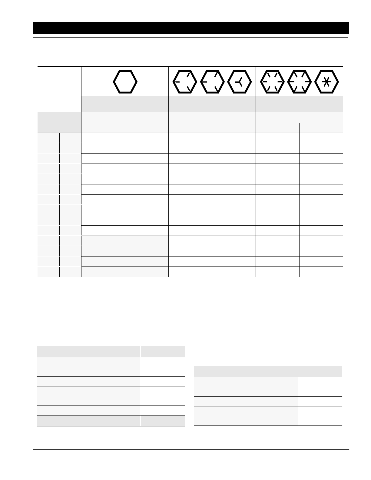
Torque Values Chart for UNC Threads
Bolt head
identification
marks are as per
grade.
NOTE: Manufacturing marks will vary.
Bolt Size
inches mm Min. Max. Min. Max. Min. Max. Min. Max. Min. Max. Min. Max.
1/4" 6.35
5/16" 7.94
3/8" 9.53
7/16" 11.11
1/2" 12.70
9/16" 14.29
5/8" 15.88
3/4" 19.05
7/8" 22.23
1" 25.40
Foot Pounds Newton-Meters Foot Pounds Newton-Meters Foot Pounds Newton-Meters
5 6 6.8 8.13 9 11 12.2 14.9 12 15 16.3 20.3
10 12 13.6 16.3 17 20.5 23.1 27.8 24 29 32.5 39.3
20 23 27.1 31.2 35 42 47.5 57.0 45 54 61.0 73.2
30 35 40.7 47.4 54 64 73.2 86.8 70 84 94.9 113.9
45 52 61.0 70.5 80 96 108.5 130.2 110 132 149.2 179.0
65 75 88.1 101.6 110 132 149.2 179.0 160 192 217.0 260.4
95 105 128.7 142.3 150 180 203.4 244.1 220 254 298.3 358.0
150 185 203.3 250.7 270 324 366.1 439.3 380 456 515.3 618.3
160 200 216.8 271.0 400 480 542.4 650.9 600 720 813.6 976.3
250 300 338.8 406.5 580 596 786.5 943.8 900 1080 1220.4 1464.5
1 1/8" 25.58
1 1/4" 31.75
1 3/8" 34.93
1 1/2" 38.10
Grade 2 Grade 5 Grade 8*
800 880 1084.8 1193.3 1280 1440 1735.7 1952.6
1120 1240 1518.7 1681.4 1820 2000 2467.9 2712.0
1460 1680 1979.8 2278.1 2380 2720 3227.3 3688.3
1940 2200 2630.6 2983.2 3160 3560 4285.0 4827.4
* Thick nuts must be used with Grade 8 bolts
NOTE: Torque requirements listed above do not apply to self-locking nuts. For self-locking nuts increase the torque requirements listed by 15%.
Tire Inflation Chart
Tire Size Inflation PSI
7.50 x 20" 4-Ply Drill Rib 28
9.0 x 22.5 10-Ply Highway Service 70 70
9.0 x 24" 8-Ply Rib Implement 40
9.5L x 15" 6-Ply Rib Implement 32
9.5L x 15" 8-Ply Rib Implement 44
9.5L x 15" 12-Ply Rib Implement 60
Tire Size Inflation PSI
5/15/06 Great Plains Mfg., Inc.
Tire Inflation Chart
Tire Size Inflation PSI
7.50 x 20" 4-Ply Drill Rib 28
9.0 x 22.5 10-Ply Highway Service 70 70
9.0 x 24" 8-Ply Rib Implement 40
9.5L x 15" 6-Ply Rib Implement 32
9.5L x 15" 8-Ply Rib Implement 44
60303P and 80303P Three-Point Planter 401-008M
-33
Page 36

Section 9 Specifications
Metric Conversion Chart
Multiply By To Get
inches in. x 2.54 = centimeters cm
inches in. x 25.4 = millimeters mm
feet ft. x 30.48 = centimeters cm
miles per hour mph x 1.609 = kilometers per
pounds lbs. x 0.453 = kilograms kg
bushels bu. x 35.238= liters l
gallons gal x 3.785 = liters l
pounds per
square inch psi
inch pounds in. lbs. x 0.113 = Newtons-meters
foot pounds ft. lbs. x 1.356 = Newtons-meters
centimeters cm x 394 = inches in.
millimeters mm x 0394 = inches in.
centimeters cm x 0328 = feet ft.
hectares ha x 2.469 = acres
kilometers per hour
kilograms kg x 2.208 = pounds lbs.
liters l x 0.028 = bushels bu.
x 6.894 = kilopascals kPa
x 0.621 = miles per hour mph
kmph
hour kmph
(100 kPa = 1 bar)
N.m
N.m
liters l x 0.264 = gallons gal.
kilopascals kPa
(100 kPa = 1 bar)
Newtons-meters N.m x 8.85 = inch pounds in lb.
Newtons-meters N.m x 0.738 = foot pounds ft lb
34
60303P and 80303P Three-Point Planter 401-008M 5/15/06
x 0.145 = pounds per
square inch psi
Great Plains Mfg., Inc.
Page 37

Section 10 Attachments & Options
Section 10 Attachments & Options
Marker Attachment
113-428K . . . . . . 6-Row 30" Flat Fold Marker
113-432K . . . . . . 8-Row 30" Flat Fold Marker
Coulter Option
204-337A . . . . . . 5/8" Wavy Coulter
204-338A . . . . . . 3/4" Wavy Coulter
Spring Package Option
204-331K . . . . . . Light Duty Springs
204-332K . . . . . . Medium Duty Springs
204-333K . . . . . . Heavy Duty Springs
Seed Lok Option
404-021K . . . . . . Seed Lok
1 x 12 Closing Wheel Option
405-001A . . . . . . 1 x 12 Closing Wheel
6.5 x 12 Press Wheel Option
405-002A . . . . . . 6.5 x 12 Press Wheel w/Closing Disk
Insecticide Option
403-017A . . . . . . 1 x 12 Insecticide in Furrow
403-018A . . . . . . 6.5 x 12 Insecticide in Furrow
403-019A . . . . . . 1 x 12 Insecticide 7" Diffuser
Insecticide & Herbicide Option
403-020A . . . . . . Insecticide Furrow & Herbicide 7"1x12
403-021A . . . . . . Insecticide Furrow & Herbicide 7" 6.5 x 12
403-022A . . . . . . Insecticide Furrow & Herbicide 14"1x12
403-023A . . . . . . Insecticide Furrow & Herbicide 14" 6.5 x 12
403-024A . . . . . . Insecticide 7" & Herbicide 7"1x12
403-025A . . . . . . Insecticide 7" & Herbicide 14"1x12
Wheel Cover Option
404-025A . . . . . . 16" Wheel Cover
5/15/06 Great Plains Mfg., Inc.
60303P and 80303P Three-Point Planter 401-008M
-35
Page 38

Section 11 Warranty
Section 11 Warranty
Great Plains Manufacturing, Incorporated warrants to the original purchaser that this seeding equipment will be free from defects in material
and workmanship for a period of one year from the date of original purchase when used as intended and under normal service and conditions
for personal use; 90 days for commercial or rental purposes. This Warranty is limited to the replacement of any defective part by Great Plains
Manufacturing, Incorporated and the installation by the dealer of any
such replacement part. Great Plains reserves the right to inspect any
equipment or part which are claimed to have been defective in material
or workmanship.
This Warranty does not apply to any part or product which in Great
Plains’ judgement shall have been misused or damaged by accident or
lack of normal maintenance or care, or which has been repaired or altered in a way which adversely affects its performance or reliability, or
which has been used for a purpose for which the product is not designed. This Warranty shall not apply if the product is towed at a speed
in excess of 20 miles per hour.
Claims under this Warranty must be made to the dealer which originally
sold the product and all warranty adjustments must by made through
such dealer. Great Plains reserves the right to make changes in materials or design of the product at any time without notice.
This Warranty shall not be interpreted to render Great Plains liable for
damages of any kind, direct, consequential, or contingent, to property.
Furthermore, Great Plains shall not be liable for damages resulting from
any cause beyond its reasonable control. This Warranty does not extend to loss of crops, losses caused by harvest delays or any expense
or loss for labor, supplies, rental machinery or for any other reason.
No other warranty of any kind whatsoever, express or implied, is
made with respect to this sale; and all implied warranties of merchantability and fitness for a particular purpose which exceed
the obligations set forth in this written warranty are herby disclaimed and excluded from this sale.
This Warranty is not valid unless registered with Great Plains Manufacturing, Incorporated within 10 days from the date of original purchase.
Warranty
36
60303P and 80303P Three-Point Planter 401-008M 5/15/06
Great Plains Mfg., Inc.
 Loading...