

Page 1
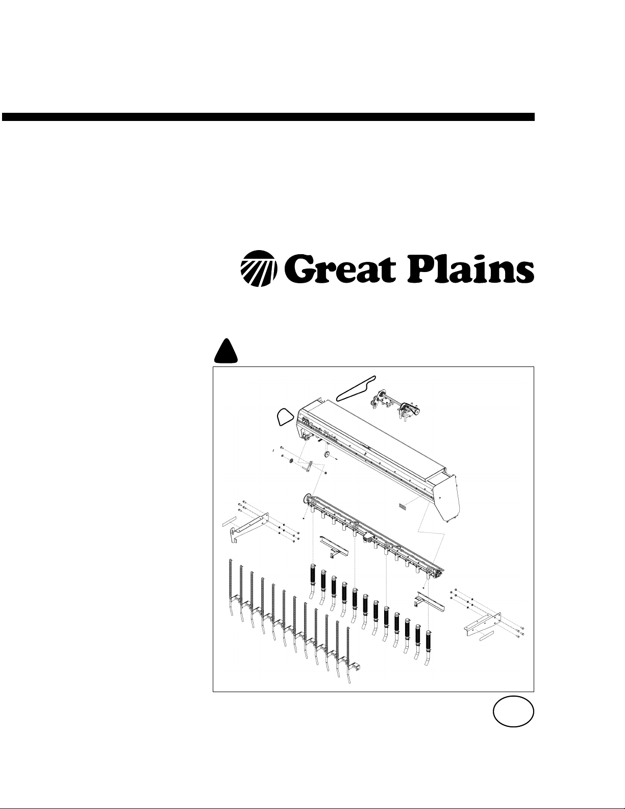
Installation Instructions
8-Foot End-Wheel Drills
800EW Fertilizer Kits
Manufacturing, Inc.
www.greatplainsmfg.com
Read the installation manual entirely. When you see this symbol, the subsequent
instructions and warnings are serious - follow without exception. Your life and
!
the lives of others depend on it!
29570
Cover illustration may show parts not supplied with all kits.
EN
© Copyright 2009 Printed 02/24/2010 175-253M
Page 2

Table of Contents
Important Safety Information.................................... 1
Introduction ................................................................ 4
Models Covered........................................................... 4
Kits Covered ................................................................ 4
Definitions ................................................................4
Call-Outs .................................................................. 4
Before You Start......................................................... 5
Drill Compatibility ......................................................... 5
Tools Required............................................................. 5
Related Documents ................................................. 5
Installing Multiple Options? .......................................... 5
Pre-Assembly Preparation ........................................... 6
Remove Existing Hardware....................................... 7
Remove Walkboard Ladder ......................................... 7
Remove Walkboard ..................................................... 7
Remove Walkboard Support(s).................................... 8
Remove Handles ......................................................... 8
Remove Transmission Chain....................................... 9
Release Hoses Near Drive .......................................... 9
Disconnect Small Seeds Hoses................................... 9
Remove Small Seeds Delivery Tubes ....................... 10
Remove Small Seeds Box ......................................... 10
Install Hardware ....................................................... 11
Install Fertilizer Box.................................................... 11
Install Drive System ................................................... 11
Install Gearbox Accessory Sprocket ...................... 11
Install Gearbox Accessory Idler/Bearing................ 12
Pre-Assemble Accessory Shaft Mount................... 13
Install Accessory Shaft Mount................................ 13
Install Accessory Shaft and Sprockets................... 14
Install Gearbox Output Chain................................. 15
Install Transmission Chain..................................... 15
Routing - Fertilizer Only ..................................... 15
Routing - Fertilizer and Agitator ......................... 15
Adjust Final Drive Chain Slack................................... 16
Install Fertilizer Delivery............................................. 16
Install Delivery Tubes............................................. 16
Install Delivery Hoses ............................................ 17
Re-Install Small Seeds Box ....................................... 18
Install SGS to Fertilizer Chain ................................... 18
Install Small Seeds Delivery ...................................... 19
Install Side Delivery Tubes ................................ 19
Install Seed Hoses................................................. 19
Install Supports and Walkboard................................. 20
Supports and Walkboard, w/o Small Seeds .......... 20
LH Walkboard Support (w/o SGS)..................... 20
Place Walkboard (w/o SGS) .............................. 21
RH Walkboard Support (w/o SGS) .................... 21
Secure Walkboard (w/o SGS)............................ 22
Supports and Walkboard, w/ Small Seeds ............ 22
Mount LH Support to Walkboard (with SGS) ..... 22
Mount RH Support to Walkboard (with SGS) .... 22
Position Walkboard on Drill (with SGS) ............. 23
Secure Walkboard (w/ SGS).............................. 23
Re-Install Ladder ....................................................... 24
Re-Install Handles ..................................................... 24
Close-Out ................................................................. 25
Apply Decals.............................................................. 25
Check Drive Operation .............................................. 25
Operation.................................................................. 26
Troubleshooting ...................................................... 27
Maintenance and Lubrication................................. 28
Chain Maintenance.................................................... 28
Maintenance .............................................................. 28
Lubrication ................................................................. 29
Appendix .................................................................. 31
New Parts .................................................................. 31
New Parts: Main Kits ............................................. 31
New Parts: Opener Side Delivery Hardware ......... 32
New Parts: Meter to Row Delivery Hardware ........ 32
New Parts: Fertilizer Trays .................................... 32
New Parts: Fertilizer Box and Lid .......................... 34
New Parts: Fertilizer Rate Adjuster Rod Assembly 35
New Parts: Accessory Drive .................................. 35
New Parts: Fertilizer Box Lid Hinge Assemblies.... 36
Existing Parts Affected .............................................. 36
Abbreviations............................................................. 38
Torque Values Chart ................................................. 39
Index ......................................................................... 41
© Copyright 2010 All rights Reserved
Great Plains Manufacturing, Inc. providesthis publication “as is” without warranty of any kind, either expressed or implied. While every precaution has been taken in the preparation
of this manual, Great Plains Manufacturing, Inc. assumes no responsibility for errors or omissions. Neither is any liability assumed for damages resulting from the use of the information contained herein. Great Plains Manufacturing, Inc. reserves the right to revise and improve its products as it sees fit. This publication describes the state of this product at
the time of its publication, and may not reflect the product in the future.
The following are trademarks of Great Plains Mfg., Inc.: Application Systems, Ausherman, Land Pride, Great Plains
All other brands and product names are trademarks or registered trademarks of their respective holders.
02/24/2010 175-253M
Great Plains Manufacturing, Incorporated Trademarks
Printed in the United States of America.
Page 3
Important Safety Information
Look for Safety Symbol
The SAFETY ALERT SYMBOL indicates there is a
potential hazard to personal safety involved and extra
safety precaution must be taken. When you see this
symbol, be alert and carefully read the message that follows it. In addition to design and configuration of equipment, hazard control and accident prevention are
dependent upon the awareness, concern, prudence and
proper training of personnel involved in the operation,
transport, maintenance and storage of equipment.
Be Aware of Signal Words
Signal words designate a degree or level of hazard seriousness.
DANGER indicates an imminently hazardous situation
which, if not avoided, will result in death or serious injury.
This signal word is limited to the most extreme situations,
typically for machine components that, for functional purposes, cannot be guarded.
WARNING indicates a potentially hazardous situation
which, if not avoided, could result in death or serious
injury, and includes hazards that are exposed when
guards are removed. It may also be used to alert against
unsafe practices.
CAUTION indicates a potentially hazardous situation
which, if not avoided, may result in minor or moderate
injury. It may also be used to alert against unsafe practices.
!
DANGER
!
WARNING
!
CAUTION
!
1
Prepare for Emergencies
▲ Be prepared if a fire starts
▲ Keep a first aid kit and fire extinguisher handy.
▲ Keep emergency numbers for doctor, ambulance, hospital
and fire department near phone.
911
Be Familiar with Safety Decals
▲ Read and understand “Safety Decals” on page 3, thor-
oughly.
▲ Read all instructions noted on the decals.
▲ Keep decals clean. Replace damaged, faded and illegible
decals.
02/24/2010 175-253M
Page 4

2 175-248A, -249A, -250A, -251A
Wear Protective Equipment
▲ Wear protective clothing and equipment.
▲ Wear clothing and equipment appropriate for the job. Avoid
loose-fitting clothing.
▲ Because prolonged exposure to loud noise can cause hear-
ing impairment or hearing loss, wear suitable hearing protection such as earmuffs or earplugs.
▲ Because operating equipment safely requires your full
attention, avoid wearing entertainment headphones while
operating machinery.
Handle Chemicals Properly
Agricultural chemicals can be dangerous. Improper use
can seriously injure persons, animals, plants, soil and
property.
▲ Do not use liquid treatments with the fertilizer kit.
▲ Read and follow chemical manufacturer’s instructions.
▲ Wear protective clothing.
▲ Handle all chemicals with care.
▲ Avoid inhaling smoke from any type of chemical fire.
▲ Never drain, rinse or wash dispensers within 100 feet of a
freshwater source, nor at a car wash.
▲ Store or dispose of unused chemicals as specified by chemi-
cal manufacturer.
▲ Dispose of empty chemical containers properly. Laws gen-
erally require power rinsing or rinsing three times, followed
by perforation of the container to prevent re-use.
175-253M 02/24/2010
Page 5
Safety Decals
Safety Reflectors and Decals
The kits covered by this manual may include new safety
decals that need to be applied. Existing safety decals on
the drill also apply during the installation. Both classes of
decals are re-listed here for emphasis.
▲ Read and follow decal directions.
▲ Keep lights in operating condition.
▲ Keep all safety decals clean and legible.
▲ Replace all damaged or missing decals. Order new decals
from your Great Plains dealer. Refer to this section for
proper decal placement.
▲ When ordering new parts or components, also request cor-
responding safety decals.
3
To install new decals:
1. Clean the area on which the decal is to be placed.
2. Peel backing from decal. Press firmly on surface,
being careful not to cause air bubbles under decal.
838-265C
Amber Reflectors
On wing walkboard end faces, above steps,
front face of frame, outside corners;
4 total
Kits include new amber reflectors for new walkboard supports.
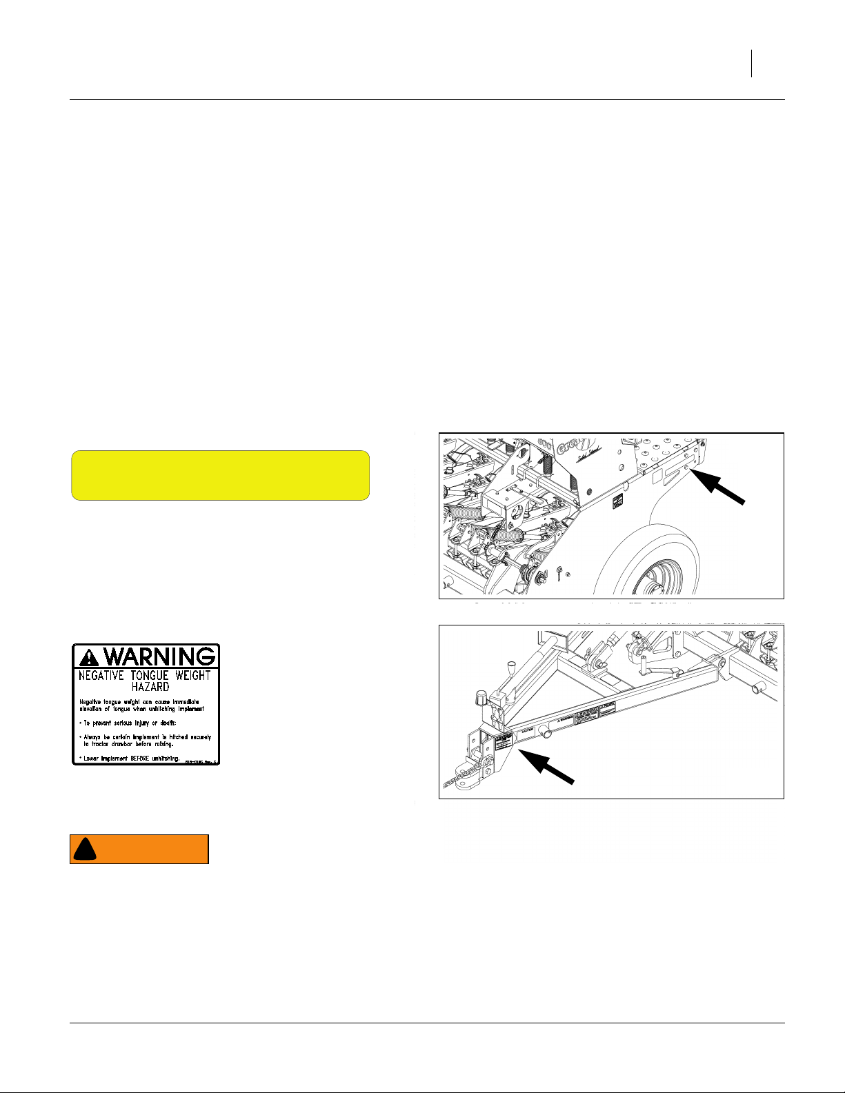
818-019C
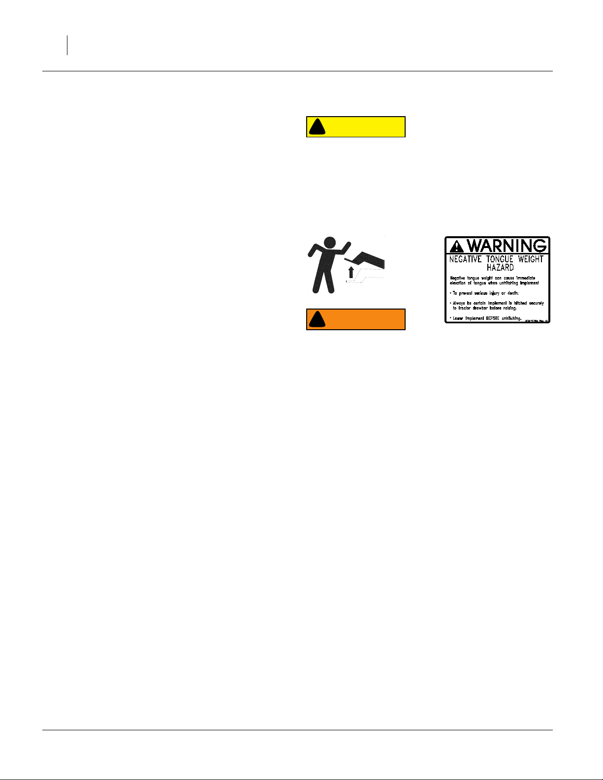
Warning: Negative Tongue Weight
Existing decal on tongue at hitch;
1 total
28203
28203
WARNING
!
Drill Becomes at Risk of Negative Tongue Weight:
An 800EW drill without the Fertilizer option would always
have positive tongue weight. With the Fertilizer option
installed, negative tongue weight is now possible when material is loaded in the fertilizer box, and when weight is on the
new extended walkboard. Unless tractor remains hitched during installation, lower drill before unhitching.
02/24/2010 175-253M
Page 6
4 175-248A, -249A, -250A, -251A
Introduction
The 800EW Fertilizer Kits add the capability to meter dry
fertilizer with the Great Plains 8-Foot End-Wheel Drill.
Material may be metered during seeding, or separately.
The fertilizer rate is independent of seed rates from main
box or Small Seeds box.
Models Covered
Drill Description
800-1275 8-Foot 12-Row 7.5in Spacing
800-1506 8-Foot 15-Row 6in Spacing
Kits Covered
This manual describes installation of four kits. Kits are
provided in two versions for each row spacing:
175-248A 800 FERT 6 FLD INST ON SGS
Use this kit with an 800-1506 drill which also has
the Small Seeds or Agitator options (or when
simultaneously installing another option which
includes an Accessory Drive).
175-249A 800 FERT 6 FLD INST WITH DRIVE
Use this kit with an 800-1506 drill which has only a
Main Seed Box without Agitator (or when simultaneously installing the Small Seeds option version
which does not include an Accessory Drive).
175-250A 800 FERT 7.5 FLD INST ON SGS
Use this kit with an 800-1275 drill which also has
the Small Seeds or Agitator options (or when
simultaneously installing another option which
includes an Accessory Drive).
175-251A 800 FERT 7.5 FLD INST WITH DRV
Use this kit with an 800-1275 drill which has only a
Main Seed Box without Agitator (or when simultaneously installing the Small Seeds option version
which does not include an Accessory Drive).
Note: These kits are for pull-type 8-foot end-wheel drill.
There are separate kits for three-point 8-foot drills.
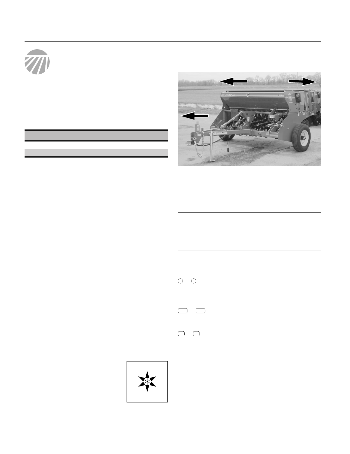
Notations and Conventions
Right-hand and left-hand as used in
this manual are determined by facing
the direction the machine will travel
while in use unless otherwise stated.
An orientation rose in some line art
illustrations shows the directions of:
Up, Back, Left, Down, Front, Right.
R
F
U
B
L
D
R
Figure 1
800 End Wheel Drill
L
29565
Definitions
The following terms are used throughout this manual.
IMPORTANT !
A crucial point of information related to the preceding
topic. Read and follow the directions to remain safe,
avoid serious damage to equipment and ensure
desired field results.
Note: Useful information related to the preceding topic.
Call-Outs
1 9
to
100
to
11 45
to
Single-digit callouts identify components in
the currently referenced Figure or Figures.
These numbers may be reused for different
items from page to page.
3-digit callouts in the range 100 to 242 refer-
242
ence new parts from the new parts lists
beginning on page 31.
2-digit callouts in the range 11 to 45 reference affected existing parts from the table
starting on page 36. The descriptions match
those in your Parts Manual. The narrative
and table indicate any re-use of the parts.
175-253M 02/24/2010
Page 7
Before You Start
Drill Compatibility
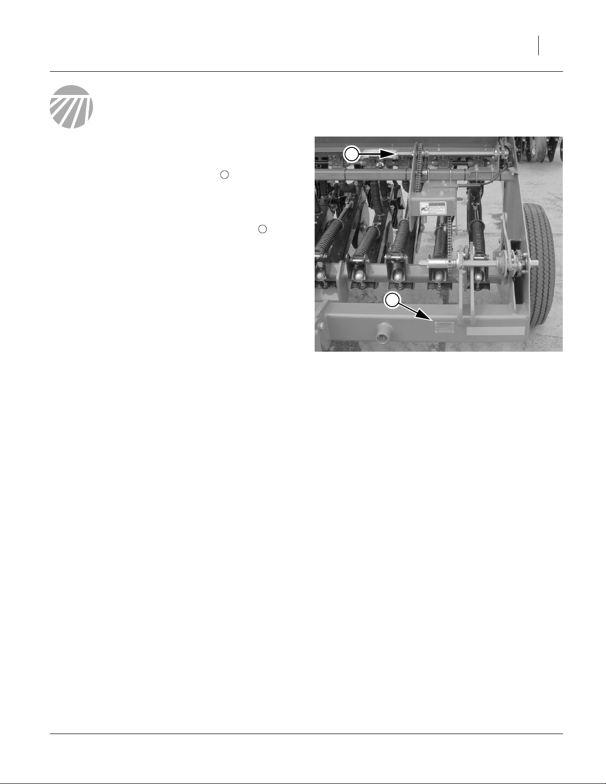
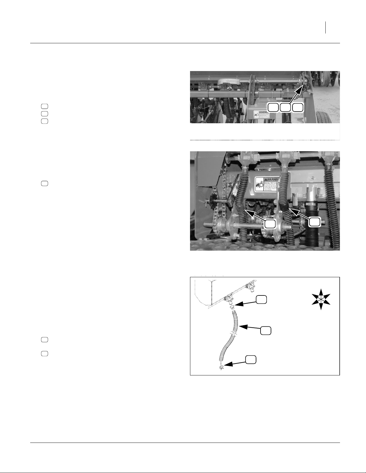
Refer to Figure 2
1. Check the drill serial number plate to ensure that
the model number is either 800-1275 or 800-1506.
These kits are not compatible with other row spacings, nor with model 3P806NT.
1
Before You Start 5
2
2. Check to see if an Accessory Drive system is
already installed (which is the case if a Main Box Agitator and/or Small Seeds is installed).
The 175-248A and 175-250A kits require that an
Accessory Drive already be present.
The 175-249A and 175-251A kits include an Accessory Drive.
2
Tools Required
• updated drill Parts manual (below) for parts I.D.
• suitable tractor for positioning and lowering drill
• chain lube
• a hoist, or at least four (4) people for large assembly
placement
• basic hand tools, including:
snap ring pliers
punch(es) for seating
Related Documents
To assist installation, and for complete and up-to-date
operating instructions for your fertilizer option, make sure
you have the current editions of the following manuals.
5
⁄
32
in and
1
⁄
in roll pins
4
1
Figure 2
Serial Number, Accessory Drive
29566
175-057M 800EW Owner’s Manual
175-057B 800EW Seed Rate Charts
175-057P 800EW Parts Manual
Updates are available on the Great Plains web, from your
dealer, or directly from Great Plains.
Installing Multiple Options?
If you are also installing a Main Box Agitator and/or the
Small Seeds attachment, perform the work in this order:
A. Agitator
B. Fertilizer
C. Small Seeds
02/24/2010 175-253M
Page 8
6 175-248A, -249A, -250A, -251A
Pre-Assembly Preparation
3. Clean out the Main and Small Seed boxes. These
boxes need to be empty for the installation.
4. Move the drill to a location with:
• room to maneuver large parts around it
• adequate lighting
• clear surface beneath for recovery of any falling or
dropped parts - if the surface is not clear, have a
tarp or drop cloth available
5. Park the drill at the work site. Install the parking jack
if unhitching (and see Warning at right).
6. Lower the openers to eliminate negative tongue
weight hazard.
7. Shut off tractor if left hitched.
CAUTION
!
Agricultural Chemical Hazard:
Installation requires hand work inside the Main seed box, and
if installed, the Small Seeds box. If treated seed has ever been
used in the seed box(es), follow seed or material supplier
instructions for safely removing residue from a seed box.
WARNING
!
Drill Becomes at Risk of Negative Tongue Weight:
An 800EW drill without the Fertilizer option has positive
tongue weight. After the Fertilizer option is installed, negative
tongue weight is possible when material is loaded in the fertilizer box, and possibly during installation when weight is on
the new extended walkboard. Unless tractor remains hitched
during installation, lower drill before unhitching
175-253M 02/24/2010
Page 9
Remove Existing Hardware
Note: Existing hardware may vary slightly from parts
called out in these instructions. Note such changes, so that parts are correctly re-installed.
Remove Existing Hardware 7
Remove Walkboard Ladder
One ladder mount is replaced when the walkboard is remounted. The ladder is re-installed at step 103 on
page 24.
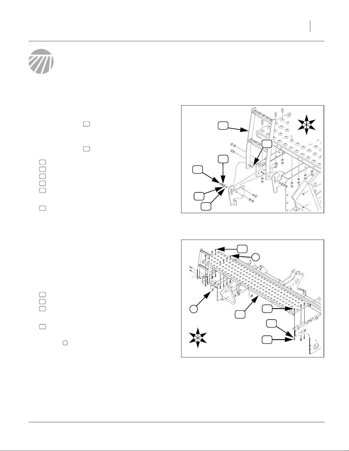
Refer to Figure 3
8. Swing the ladder down, then remove and save
two sets:
35
803-014C NUT HEX 3/8-16 PLT
42
804-013C WASHER LOCK SPRING 3/8 PLT
41
804-011C WASHER FLAT 3/8 USS PLT
12
119-278D
29
802-079C HHCS 3/8-16X1 1/4 GR5
then remove and save the ladder:
13
119-294H 3PT HINGED WALKBOARD LADDER
13
13
WALKBOARD LADDER PIVOT BUSHING
Remove Walkboard
The new fertilizer box mounts where the walkboard is
presently installed, requiring walkboard relocation. The
walkboard is re-installed on new supports at “Install
Supports and Walkboard” on page 20.
Refer to Figure 4
9. Remove and save six (6) sets:
36
803-015C NUT HEX 7/16-14 PLT
43
804-014C WASHER LOCK 7/16 PLT
33
802-673C HHCS 7/16-14X1 1/4 GR5 PLT
then remove and save the:
19
175-411D 8FT EW WALKBOARD
Note: Do not remove the hardware at the right ladder
mount . This mount stays with the walkboard and
is re-used as presently installed on the walkboard.
3
L
B
35
3
41
U
D
12
F
R
13
42
Figure 3
Dismount Ladder
33
3
19
Figure 4
Dismount Walkboard
29
33
36
43
L
B
U
F
R
D
28055
28055
02/24/2010 175-253M
Page 10
8 175-248A, -249A, -250A, -251A
Remove Walkboard Support(s)
All short supports are replaced by longer supports in
“Install Supports and Walkboard” on page 20.
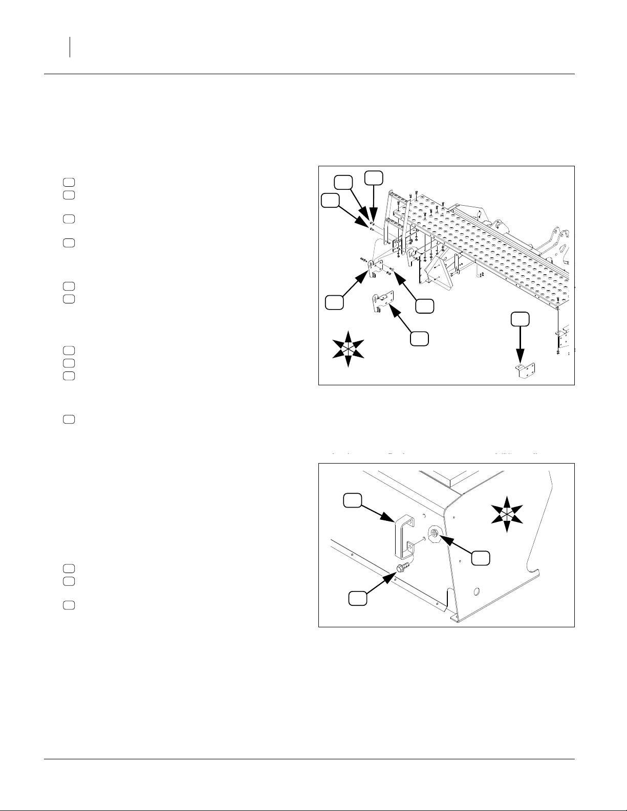
Refer to Figure 5
10. At the left frame, remove and save four (4) sets of:
37
803-020C NUT HEX 1/2-13 PLT
44
804-015C WASHER LOCK SPRING 1/2 PLT
and three (3)
29
802-079C HHCS 3/8-16X1 1/4 GR5
and one (1)
31
802-214C RHSNB 1/2-13X1 1/4 GR5
These parts are not re-used.
Then remove one of:
20
175-413D SEED ONLY LH LADDER MNT
21
175-416D LH WLK BRD SUPP SML SEEDS
This support is not re-used.
11. If the drill has the Small Seeds option, at the right
frame, remove and save four (4) sets of:
37
803-020C NUT HEX 1/2-13 PLT
44
804-015C WASHER LOCK SPRING 1/2 PLT
29
802-079C HHCS 3/8-16X1 1/4 GR5
These parts are not re-used.
Then remove one:
22
175-417D RH WLK BRD SUPP SML SEEDS
This support is not re-used.
29
L
B
20
37
44
31
U
F
21
R
D
Figure 5
Dismount Walkboard Extension(s)
22
28055
Remove Handles
If the Small Seeds attachment is installed, skip to
step 13, as the handles remain on the SGS box after
Fertilizer installation.
Refer to Figure 6
12. At each grab handle on the back corners of the main
seed box, remove and save two sets (four sets total)
of:
30
802-203C HFSS 1/2-13X1 1/2 GR5
38
803-169C NUT HEX FLG. LOCK 1/2-13 PLT.
and two:
11
119-190D HANDLE
The handles are re-mounted on the new Fertilizer
box at step 107 on page 24. The lights (not shown in
the Figure) remain on the Main Seed box.
11
30
L
B
38
Figure 6
Dismount Grab Handle
U
F
R
D
18651
175-253M 02/24/2010
Page 11
Remove Transmission Chain
If an Accessory Drive system is not yet installed on this
drill, skip to step 21 on page 11.
Refer to Figure 7
13. Remove one of:
16
136-014D CHAIN RL #40 79 PITCHES
17
136-096D CHAIN RL #40 76 PITCHES
18
136-250D CHAIN RL #40 96 PITCHES
This chain is replaced by a new chain in the kit,
which may or may not be the same part number.
Release Hoses Near Drive
Refer to Figure 8
14. Loosen fasteners securing each of two:
23
800-064C HOSE CLIP 13/16 ID
Remove Existing Hardware 9
16 17
Figure 7
Accessory Transmission Chain
18
29566
Disconnect Small Seeds Hoses
If Small Seeds (SGS) is not installed on this drill, continue at step 21 on page 11.
The existing SGS hoses are replaced by new hoses to
side delivery tubes, at step 75 on page 19.
Refer to Figure 9
15. At each row, release and remove two (2) each:
24
800-321C HOSE CLAMP NO.12 3/4 ID
and one (1)
45
816-513C SGS HOSE 85 RIBS
These parts are not re-used.
23
Figure 8
Small Seeds Final Drive
24
45
24
Figure 9
Remove Small Seeds Hose
23
29008
U
F
L
R
B
D
28212
02/24/2010 175-253M
Page 12
10 175-248A, -249A, -250A, -251A
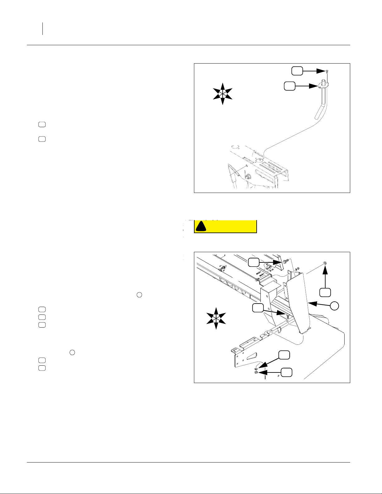
Remove Small Seeds Delivery Tubes
If Small Seeds (SGS) is not installed on this drill, continue at step 21 on page 11.
The existing SGS delivery tubes occupy the row unit hole
required for fertilizer. New SGS side delivery hardware is
installed at step 70 on page 19.
16. At each row, remove two:
25
801-002C SCREW HEX SLT10-16X1/2P.THD CT
and one
14
123-939H SMALL SEEDS TUBE WELDMENT
These parts are not re-used.
Remove Small Seeds Box
If Small Seeds (SGS) is not installed on this drill, continue at step 21 on page 11.
The Small Seeds box is re-mounted, on the new Fertilizer box, at step 63 on page 18.
Refer to Figure 11 (shown in exploded view for clarity - remove only specified fasteners - in particular, do not removethe
jackshaft and final drive assembly at the left end)
17. At each base of the box end mount , remove and
save one sets (two sets total):
28
802-034C HHCS 1/2-13X1 1/4 GR5
44
804-015C WASHER LOCK SPRING 1/2 PLT
37
803-020C NUT HEX 1/2-13 PLT
18. Support the weight of the Small Seeds box.
19. At the upper forward faces of each base of the box
end mount , remove and save two sets (four total):
30
802-203C HFSS 1/2-13X1 1/2 GR5
38
803-169C NUT HEX FLG. LOCK 1/2-13 PLT.
20. Remove the Small Seeds box from the drill.
4
4
25
U
F
L
R
B
14
D
Figure 10
Remove Small Seeds Delivery
CAUTION
!
A hoist or at least three (3) people are required. The empty
Small Seeds assembly weighs approximately 200 pounds (91
28212
30
38
L
B
U
F
R
28
4
D
44
37
Figure 11
Dismount Small Seeds Box
28098
175-253M 02/24/2010
Page 13
Install Hardware
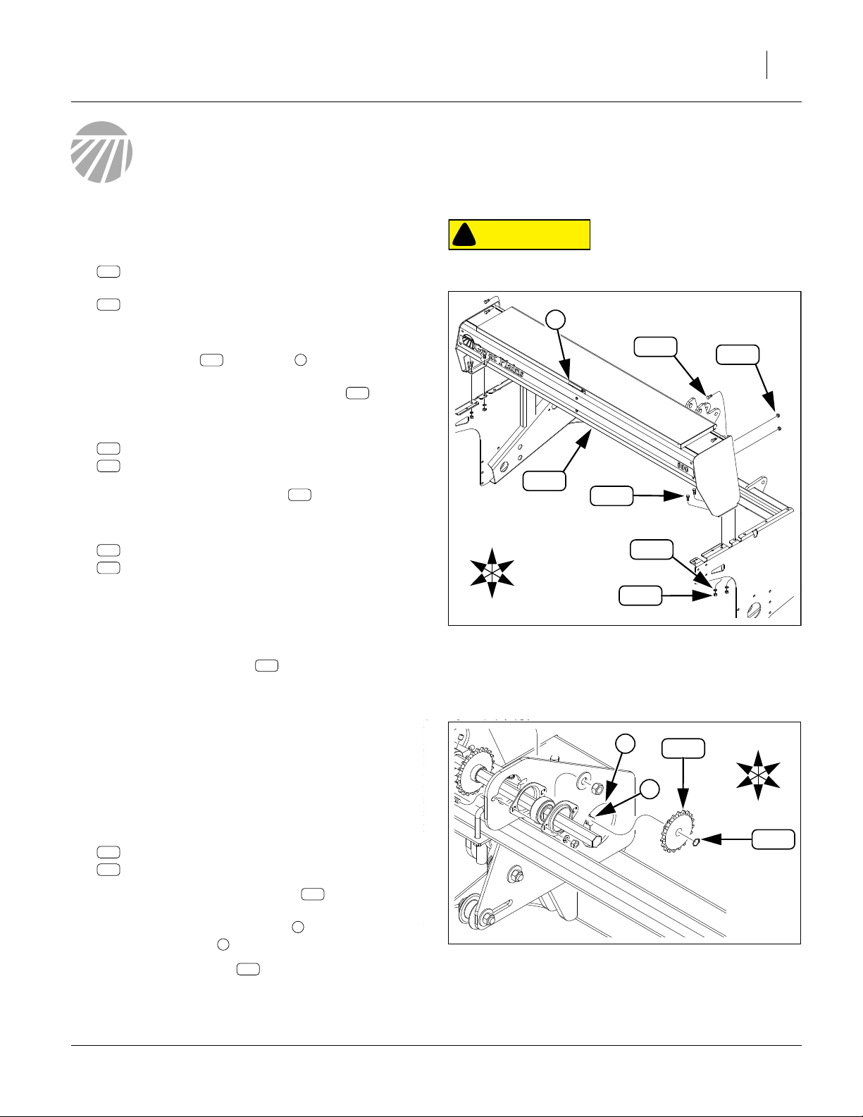
Install Fertilizer Box
Install Hardware 11
Refer to Figure 12
21. Select four (4) new:
172
802-034C HHCS 1/2-13X1 1/4 GR5
and one new:
135
142-266L FERT. BOX & LID ASY
(This box should have the 142-264K or 142-267K
tray assembly already mounted.)
22. Position the box , with latch to rear, fully forward against the main seed box (not shown). Tempo-
rarily secure it by inserting the four bolts through
holes in the lower side walls and drill side frames.
23. Select four (4) sets new:
204
804-015C WASHER LOCK SPRING 1/2 PLT
191
803-020C NUT HEX 1/2-13 PLT
Loosely add these to the bolts inserted at
step 22.
24. Select four (4) sets new:
172
802-034C HHCS 1/2-13X1 1/4 GR5
195
803-169C NUT HEX FLG. LOCK 1/2-13 PLT.
Insert these through the forward end wall flanges of
the fertilizer box, and into the main seed box holes
left open when removing the handles (step 12) or the
Small Seeds box (step 19).
25. Tighten all eight (8) bolts .
135
1
172
172
172
CAUTION
!
A hoist or at least four (4) people are required. The empty Fertilizer box weighs approximately 300 pounds (136 kg).
1
172
195
135
172
U
L
B
F
R
D
Install Fertilizer Box
204
191
Figure 12
29568
Install Drive System
If an Accessory Drive system is already installed, skip to
“Install Transmission Chain” on page 15, as only the
transmission chain needs to be installed.
Install Gearbox Accessory Sprocket
Refer to Figure 13
26. Select one (1) set new:
219
808-157C SPKT 40B19 X 36T SPLINE BORE
165
800-141C SNAP RING EXT F/PEERLESS G.B.
27. With the flat face of the sprocket to the right
(away from gearbox), place the sprocket through the
gearbox weldment access hole , and onto the front
right gearbox shaft .
28. Secure with snap ring .
02/24/2010 175-253M
3
165
219
2
Gearbox Accessory Sprocket
2
Figure 13
219
3
L
B
U
F
R
D
165
28230
Page 14
12 175-248A, -249A, -250A, -251A
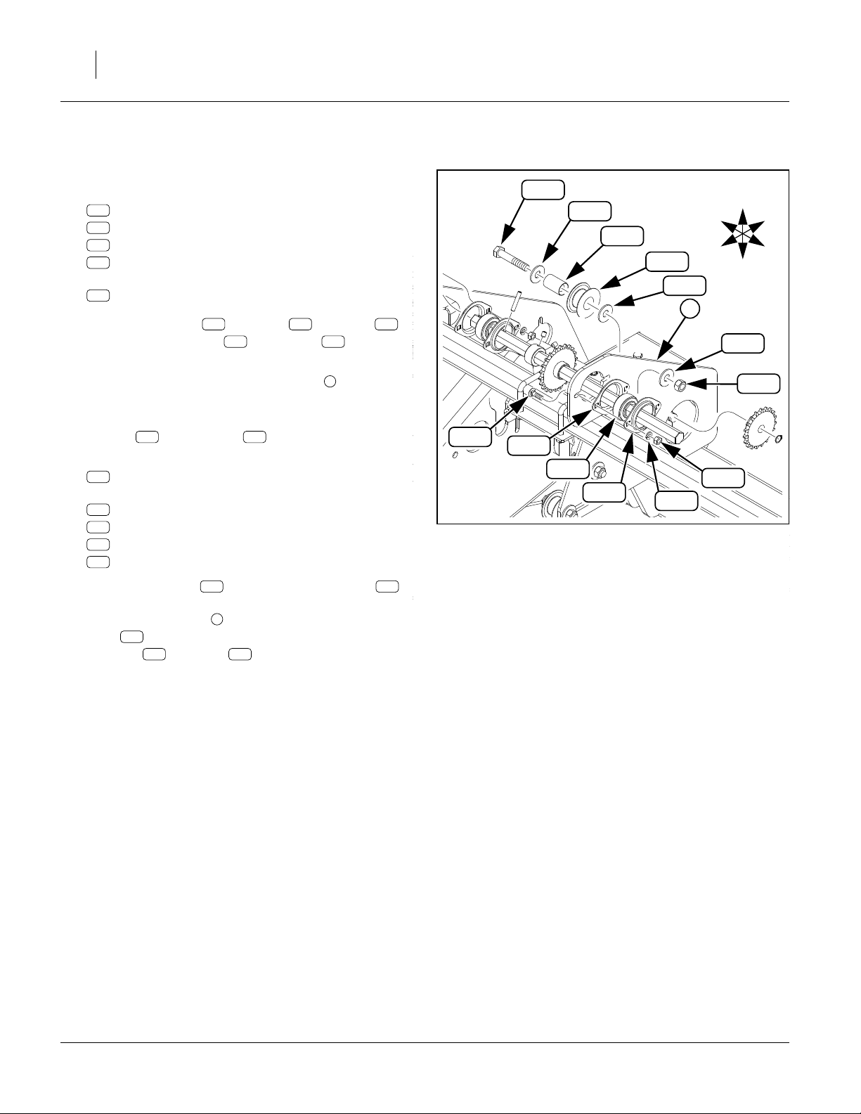
Install Gearbox Accessory Idler/Bearing
Refer to Figure 14
29. Select one (1) set new:
179
802-226C HHCS 1/2-13X2 3/4 GR5
103
120-305D TUBE RND 1 OD X 7/32W X 1.56
229
817-406C IDLER 1 PC 2.38X1.01X1.062
195
803-169C NUT HEX FLG. LOCK 1/2-13 PLT.
and three (3) new:
206
804-017C WASHER FLAT 1/2 USS PLT
Place one washer , the tube , the idler
and a second washer on the bolt .
30. Insert this assembly, from drill left, into the vertical
idler slot (not shown) in the right plate of the gear-
box mount weldment.
31. Loosely secure idler assembly with a third
washer and lock nut .
32. Select one (1) new:
235
and two sets new:
232
181
201
188
33. Place the bearing between two flangettes .
Position assembly against the right side of the gear-
box weldment plate at the bearing cutout. Insert
bolts from left, and loosely secure with lock
washers and nuts .
206
822-195C BRG INS 7/8HEXX2.04OD SPH
822-032C FLANGETTE 52 MST
802-282C RHSNB 5/16-18X1 GR5
804-009C WASHER LOCK SPRING 5/16 PLT
803-008C NUT HEX 5/16-18 PLT
181
201 188
206 103 229
206 179
4
195
235 232
4
181
179
206
103
229
206
4
232
235
232
Figure 14
Gearbox Accessory Idler/Bearing
201
L
B
188
U
F
R
D
206
195
28230
175-253M 02/24/2010
Page 15

Pre-Assemble Accessory Shaft Mount
Refer to Figure 15
34. Select one (1) new:
149
175-414D 8FT EW AUX JACK SHAFT MNT
two (2) sets new:
179
802-226C HHCS 1/2-13X2 3/4 GR5
103
120-305D TUBE RND 1 OD X 7/32W X 1.56
229
817-406C IDLER 1 PC 2.38X1.01X1.062
195
803-169C NUT HEX FLG. LOCK 1/2-13 PLT.
and six (6) new:
206
804-017C WASHER FLAT 1/2 USS PLT
35. Place one washer , the tube , the idler
and a second washer on each bolt .
36. Insert each idler assembly into the idler slots of
the mount , from the (left) side of the mount
opposite the U-bolt mounting holes . Loosely
secure with lock washers and nuts .
37. Select one (1) new:
235
822-195C BRG INS 7/8HEXX2.04OD SPH
and two sets new:
232
822-032C FLANGETTE 52 MST
181
802-282C RHSNB 5/16-18X1 GR5
201
804-009C WASHER LOCK SPRING 5/16 PLT
188
803-008C NUT HEX 5/16-18 PLT
38. Place the bearing between two flangettes .
Position assembly against the right side of the mount
at the bearing cutout. Insert bolts from left, and
loosely secure with lock washers and nuts .
149
206 103 229
206 179
5
6
206
235 232
195
181
201 188
179
206
206
206
Install Hardware 13
229
103
232
5
195
Figure 15
Accessory Shaft Mount
181
235
149
6
L
B
232
U
F
R
D
188201
28230
Install Accessory Shaft Mount
Refer to Figure 16 (which depicts the completed installation)
39. Select and two (2) new:
214
806-004C U-BOLT 3/8-16 X 2 X 2 3/4
and four (4) sets new:
203
804-013C WASHER LOCK SPRING 3/8 PLT
190
803-014C NUT HEX 3/8-16 PLT
40. Position the accessory shaft mount , with the
bearing/idler break up and to drill left, on the top of
the front top tool bar , left of the gearbox. Loosely
secure with U-bolts , lock washers and
190
nuts .
41. Adjust the mount horizontally until there is a gap of:
02/24/2010 175-253M
3
2
2
⁄
in (52.4mm)
32
between the left face of the bearing/idler plate and
the right edge of the drill’s end wall breaks . It may
be necessary to adjust or relocate a cable , to
reach final mount position.
1
214
149
203
3
4
1
203
214
Figure 16
Install Accessory Shaft Mount
190
149
3
4
2
29562
Page 16

14 175-248A, -249A, -250A, -251A
Install Accessory Shaft and Sprockets
Refer to Figure 17
42. Select one (1) each new:
150
175-415D 8FT EW AUX JACK SHAFT
222
808-250C SPKT 40C22 X 7/8 HEX BORE
159
402-058D COLLAR LOCK 7/8 HEX
43. One end of the shaft has two holes ( and ).
150
Insert this end, from drill right, through the right
(jackshaft input) bearing .
7
5 6
213
221
U
L
8
B
213
F
R
D
As the shaft clears the input bearing , add the
22T input sprocket . There is no preference on
150
222
7
hub orientation.
Continue inserting shaft, and add the lock collar .
Continue inserting the shaft through the left (jackshaft output) bearing . Leave the right shaft pin
6
hole visible on the right side of the output
bearing .
8
8
44. Select one (1) new:
213
805-180C PIN ROLL 1/4 X 1 1/2 LG PLT
Check that the right shaft hole is on the right side
of the output bearing . Drive the pin through
the right hole in the shaft . Slide the shaft fully
5
8
to drill left, against the pin .
5
213
150
213
45. Select one (1) new:
221
808-219C SPKT 40C12 X 7/8 HEX BORE
Add the 12T output sprocket to the left end of
the shaft . There is no preference on hub orienta-
150
221
tion.
46. Select one (1) new:
213
805-180C PIN ROLL 1/4 X 1 1/2 LG PLT
159
6
5
159
Figure 17
Accessory Shaft
170
222
7
150
28230
Check that the left shaft hole is on the left side of
the output sprocket . Drive the pin through
the left hole in the shaft .
6
221
6
213
150
47. Check that shaft spins freely, and tighten the four
nuts holding the flangettes.
48. If not already present in the lock collar , select
159
two (2) new:
170
801-035C SCREW SET 5/16-18 SKT KP X 3/8
Slide the lock collar fully to drill right and secure with
set screws .
175-253M 02/24/2010
170
Page 17

Install Hardware 15
Install Gearbox Output Chain
Review chain clip and slack reference information on
page 28 before installation.
Refer to Figure 18
49. Select one (1) new:
111
136-036D CHAIN RL #40 70 PITCHES
Route chain :
around gearbox accessory sprocket ,
around accessory shaft input sprocket , and
over gearbox accessory idler .
50. Adjust idler for recommended slack.
111
219
222
229
229
Install Transmission Chain
51. Select one new:
113
136-250D CHAIN RL #40 96 PITCHES
Routing - Fertilizer Only If optional Agitator is installed, continue at “Routing -
Fertilizer and Agitator”.
Refer to Figure 19
52. Observing the clip orientation instructions on page
13, route the chain :
around accessory shaft output sprocket ,
around fertilizer jackshaft shaft input sprocket ,
under rear idler , and
over front idler .
53. Continue at step 55.
113
221
220
229
229
221
229
222
111
229
219
Figure 18
Gearbox/Jackshaft Chain Routing
113
229
Figure 19
Fertilizer Chain Routing
220
U
F
B
D
28304
U
F
B
D
28305
Routing - Fertilizer and Agitator
If optional Agitator is not installed, use the steps at
“Routing - Fertilizer Only” above.
Refer to Figure 20
54. Observing the clip orientation instructions on page
13, route the chain :
around accessory shaft output sprocket ,
over agitator shaft input sprocket ,
around fertilizer jackshaft shaft input sprocket ,
under rear idler , and
over front idler .
55. Adjust idlers for recommended slack.
02/24/2010 175-253M
113
221
9
220
229
229
229
221
229
229
Fertilizer+Agitator Chain Routing
9
Figure 20
113
F
220
U
B
D
28307
Page 18

16 175-248A, -249A, -250A, -251A
Adjust Final Drive Chain Slack
Refer to Figure 21
Although the final drive chain on the fertilizer box is
factory-installed, it may not be adjusted for ideal slack.
56. Review chain clip and slack reference information on
page 28. Adjust idler for recommended slack.
112
229
112
F
229
U
B
D
Install Fertilizer Delivery
Small Seeds hoses, if present, are reconnected at
step 77 on page 19.
Install Delivery Tubes
Tubes may be oriented forward or backward, based on
user preference and other installed options.
Refer to Figure 22
57. At each row unit, select one (1) each new:
107
133-065D SML SDS TB REINFORCEMENT RING
228
817-346C PLASTIC FERTILIZER TUBE
and two (2) new:
168
801-002C SCREW HEX SLT10-16X1/2P.THD CT
Insert the fertilizer tube in the rear delivery
2
hole of the opener frame. Add a reinforcement
107
ring and secure with two self-tapping
screws .
168
228
Figure 21
Fertilizer Final Chain Routing
168
2
Figure 22
Fertilizer Delivery Tube
28305
107
228
16459
175-253M 02/24/2010
Page 19

Install Delivery Hoses
Start with the left-most fertilizer meter (row 1) on the drill,
and complete both of the step 58 through step 61 for
each row before moving to the next row. Meters are not
always directly above the rows they serve.
Refer to Figure 23
58. At each row unit, select one (1) each new:
162
800-016C
223
816-239C SEED HOSE 56 RIBS X 11 LONG
UPPER FERT HOSE CLAMP RATCHET
Install Hardware 17
3
One end of the hose has a 1
and the other end a 1
clamp onto the larger 1
162
59. Slide the larger 1
223
1
⁄
in (31.8mm) I.D. Slide the
4
1
⁄
in end of the hose fully (about 2in
2
or 5cm) onto to the fertilizer drop tube for the cur-
1
⁄
in (38.1mm) I.D.,
2
1
⁄
in end of the hose.
2
3
rent row.
Slide the clamp until it is centered about 1in (2.5cm)
below the end of the hose. Tighten the clamp.
60. Select one (1) new:
160
800-008C CLAMP HOSE 1 1/2 NO. 24
Open this clamp and slide it fully onto the smaller
1
1
⁄
in end of the hose, up against the ribs.
4
61. Slide the smaller 1
top of the fertilizer tube .
Open the clamp and release it about
above the reinforcement ring , measured near
the screw .
168
1
⁄
in end of the hose fully over the
4
228
1
⁄
in (13mm)
2
107
62. Repeat step 58 through step 61 for each row.
168
Figure 23
Fertilizer Delivery Hose
162
223
160
107
228
16459
02/24/2010 175-253M
Page 20

18 175-248A, -249A, -250A, -251A
Re-Install Small Seeds Box
If the drill did not previously have a Small Seeds box
installed, continue at “Re-Install Ladder” on page 24.
Refer to Figure 24
63. Check that the four
the upper corners of the rear face of the fertilizer box
are open. If not remove any fasteners used to plug
those holes. This hardware is not re-used.
64. Select four (4) sets saved:
30
802-203C HFSS 1/2-13X1 1/2 GR5
38
803-169C NUT HEX FLG. LOCK 1/2-13 PLT.
65. Position the Small Seeds box , with lid latches (not
shown) to the rear, directly behind the new fertilizer
box. Insert bolts through forward face of end
plates, through handle holes in fertilizer box. Loosely
secure with lock nuts .
66. Select four (4) sets saved:
28
802-034C HHCS 1/2-13X1 1/4 GR5
44
804-015C WASHER LOCK SPRING 1/2 PLT
37
803-020C NUT HEX 1/2-13 PLT
67. Insert bolts through lower break of Small Seeds
box end plates, and then through top break of side
frame. Add lock washers and nuts . Tighten all
eight nuts ( , ).
28
37 38
9
/
in (14mm) handle holes at
16
2
30
38
44 38
1
CAUTION
!
A hoist or at least three (3) people are required.
The empty Small Seeds assembly weighs approximately
200 pounds (91 kg).
30
38
2
28
1
U
L
B
F
R
D
Figure 24
Re-mount Small Seeds Box
44
37
29569
Install SGS to Fertilizer Chain
If the drill did not previously have a Small Seeds box
installed, continue at “Re-Install Ladder” on page 24.
Review chain clip and slack reference information on
page 28 before installation.
Refer to Figure 25
68. Select one (1) new:
110
136-014D CHAIN RL #40 79 PITCHES
Route chain :
around fertilizer jackshaft output sprocket ,
around SGS jackshaft input sprocket , and
over SGS input idler .
69. Adjust idler for recommended slack.
110
217
17T
12i
12i
110
217
Figure 25
Fertilizer-SGS Chain Routing
F
U
B
D
17T
12i
28307
175-253M 02/24/2010
Page 21

Install Small Seeds Delivery
If the drill did not previously have a Small Seeds box
installed, continue at “Re-Install Ladder” on page 24.
197
Install Hardware 19
3
Install Side Delivery Tubes
Start with the left-most row unit.
Refer to Figure 26 (fertilizer delivery tube not depicted)
70. For each row, select one each new:
108
133-128H SGS SIDE DELIVERY TUBE
185
802-427C HFS 3/8-16X3 3/4 SPTHD
197
803-209C NUT FLANGE LOCK 3/8-16 PLT
71. Orient the side tube weldment with the delivery
tube to the left of the row unit, and the mount ahead
of the fertilizer delivery tube hole .
72. Insert a bolt through mount and the row unit
frame at hole . Secure with lock nut .
73. Repeat step 70 through step 72 for each row unit.
185
4
108
3
197
Install Seed Hoses
Start with the left-most row unit (row 1).
74. At rows 1 and 2, route the hose through clips of
the SGS final drive as shown in Figure 8 on page 9.
Refer to Figure 27
75. Select one new:
224
816-513C SGS HOSE 85 RIBS
and two new:
166
800-321C HOSE CLAMP NO.12 3/4 ID
23
108
185
4
U
R
F
B
L
D
Figure 26:
Small Seeds Side Delivery Tube
with Fertilizer
Note: Feeder cups may not be directly above the row unit
to which their hose connects.
27450
76. Open a hose clamp and place it over an end of
the hose . Move the clamp down to the start of
the ribbed section.
77. Slide the top of the hose onto the meter drop
tube of the fluted feed cup for that row, so that the
hose completely covers the straight portion of the
exit tube. Open the clamp and position it about
(6mm) above the bottom of the exit tube.
At rows 1 and 2, tighten hose clips (see Figure 8
on page 9).
78. Open a hose clamp and place it over the other
end of the hose . Move the clamp up from the
end of the hose.
79. Slide the bottom end of the hose onto the top of
the delivery tube , so that it completely covers the
exposed portion of the tube. Open the clamp and
position it about
hose.
80. Repeat step 75 through step 79 for each row unit.
02/24/2010 175-253M
224
5
166
224
23
166
224
224
6
1
⁄
in (13mm) from the end of the
2
5
166
1
⁄
in
4
L
B
U
224
6
F
R
166
D
Figure 27:
Small Seeds Drop Tubes
29576
Page 22

20 175-248A, -249A, -250A, -251A
Install Supports and Walkboard
Steps depend on drill configuration. The edge channels
of the walkboard wrap around support and/or frame
breaks. Using a specific order eases the tasks.
• If Small Seeds was not installed on the drill, continue
at step 81 below.
• If Small Seeds was installed on the drill, continue at
step 95 on page 22.
The decal application is covered in a later section of this
manual.
Supports and Walkboard, w/o Small Seeds
LH Walkboard Support (w/o SGS)
Refer to Figure 28
81. Select one (1) each new:
120
142-077D LH WLK BRD SUPP FERT
178
802-214C RHSNB 1/2-13X1 1/4 GR5
204
804-015C WASHER LOCK SPRING 1/2 PLT
191
803-020C NUT HEX 1/2-13 PLT
82. Position the support , break up, inside the left
side rear frame. Insert the round head bolt , from
outside drill left, at the top front hole . Loosely
secure with lock washer and nut .
83. Select and three (3) sets new:
172
802-034C HHCS 1/2-13X1 1/4 GR5
204
804-015C WASHER LOCK SPRING 1/2 PLT
191
803-020C NUT HEX 1/2-13 PLT
Insert hex head bolts from the outside, at the
remaining support-to-frame holes. Loosely secure
with lock washer and nut .
120
204
172
204 191
178
6
191
172
178
6
120
Figure 28
Walkboard Left Support (w/o SGS)
204
L
B
191
U
F
R
D
29572
175-253M 02/24/2010
Page 23

Place Walkboard (w/o SGS)
Refer to Figure 29
84. Two people are needed for the next three steps.
Select the saved:
19
175-411D 8FT EW WALKBOARD
and two saved:
33
802-673C HHCS 7/16-14X1 1/4 GR5 PLT
85. Elevate walkboard above side frames. Slide the left
end of the walkboard over the top break of the left
support and over the rear tab of the left side
frame top break. Insert a bolt in the front left end
tread hole.
86. Lower right front channel of walkboard into gap
ahead of rear tab of right frame top break. Insert a
bolt in the front right end tread hole.
120
33
19
7
33
8
L
120
U
Install Hardware 21
7
8
33
19
33
F
RH Walkboard Support (w/o SGS)
Refer to Figure 30
87. Select one (1) each new:
119
142-064D RH WLK BRD SUPP FERT
178
802-214C RHSNB 1/2-13X1 1/4 GR5
204
804-015C WASHER LOCK SPRING 1/2 PLT
191
803-020C NUT HEX 1/2-13 PLT
88. Maneuver the support so that the top break is
between the walkboard channels and the face with
the four bolt slots is inside the right drill frame.
89. Insert the round head bolt from the outside
(right) at the top front bolt hole. Loosely secure with
lock washer and nut .
90. Select and three (3) sets new:
172
802-034C HHCS 1/2-13X1 1/4 GR5
204
804-015C WASHER LOCK SPRING 1/2 PLT
191
803-020C NUT HEX 1/2-13 PLT
Insert hex head bolts from the outside, at the
remaining support-to-frame holes. Loosely secure
with lock washer and nut .
204 191
119
178
172
204 191
B
R
D
Figure 29
Position Walkboard (w/o SGS)
191
204
Figure 30
RH Walkboard Support (w/o SGS)
178
L
B
29572
U
F
R
D
172
119
29572
02/24/2010 175-253M
Page 24

22 175-248A, -249A, -250A, -251A
Secure Walkboard (w/o SGS)
Refer to Figure 31
91. Select four (4) saved:
33
802-673C HHCS 7/16-14X1 1/4 GR5 PLT
33
19
Insert bolts in rear corner, and center end tread
holes of walkboard .
92. Select six (6) sets saved:
43
804-014C WASHER LOCK 7/16 PLT
36
803-015C NUT HEX 7/16-14 PLT
Add lock washers and nuts to all walkboard
bolts.
93. Tighten all walkboard and support bolts.
94. Continue at “Re-Install Ladder” on page 24.
33
19
43 36
Supports and Walkboard, w/ Small Seeds
Mount LH Support to Walkboard (with SGS)
Refer to Figure 32
95. Select one (1) each new:
138
142-298D RH WLK BRD SUPP SML SDS-FERT
the saved:
19
175-411D 8FT EW WALKBOARD
and three (3) sets saved:
33
802-673C HHCS 7/16-14X1 1/4 GR5 PLT
43
804-014C WASHER LOCK 7/16 PLT
36
803-015C NUT HEX 7/16-14 PLT
96. With the break up, and the slotted end to the rear,
mount the LH support under the top left edge of
the walkboard . Insert bolts from above
through tread holes. Loosely secure with lock
washers and nuts .
19 33
43 36
138
36
43
36
Figure 31
Secure Walkboard (w/o SGS)
138
33
43
Figure 32
Walkboard LH Support (w/ SGS)
33
19
L
B
29572
U
F
R
D
29573
Mount RH Support to Walkboard (with SGS)
Refer to Figure 33
97. Select one (1) new:
139
142-312D LH WLK BRD SUPP SML SDS-FERT
and three (3) sets saved:
33
802-673C HHCS 7/16-14X1 1/4 GR5 PLT
43
804-014C WASHER LOCK 7/16 PLT
36
803-015C NUT HEX 7/16-14 PLT
98. With the break up, and the four-hole end to the front,
mount the LH support under the top left edge of
the walkboard . Insert bolts from above
through tread holes. Loosely secure with lock
washers and nuts .
175-253M 02/24/2010
19 33
43 36
138
43
36
Walkboard RH Support (w/ SGS)
19
33
Figure 33
B
U
L
F
R
D
139
29573
Page 25

Position Walkboard on Drill (with SGS)
Two people are needed for the next two steps.
Refer to Figure 34
99. Select and two (2) sets new:
172
802-034C HHCS 1/2-13X1 1/4 GR5
204
804-015C WASHER LOCK SPRING 1/2 PLT
191
803-020C NUT HEX 1/2-13 PLT
100.Maneuver the walkboard/support assembly so that
the four-hole bolt faces of the supports are inside
the rear side frames.
At each side, insert one hex head bolt from the
outside, at the upper rear hole. Loosely secure with
lock washer and nut .
204 191
9
172
Install Hardware 23
172
9
204
191
L
B
U
F
R
D
191
172
204
9
Secure Walkboard (w/ SGS)
Refer to Figure 35
101.Select four (4) sets new:
172
802-034C HHCS 1/2-13X1 1/4 GR5
204
804-015C WASHER LOCK SPRING 1/2 PLT
191
803-020C NUT HEX 1/2-13 PLT
Insert hex head bolts from the outside, at the
remaining support-to-frame holes. Loosely secure
with lock washer and nut .
102.Tighten all walkboard and support bolts.
172
204 191
191
Figure 34
Position Walkboard (w/ SGS)
1
204
Figure 35
Secure Walkboard (w/ SGS)
29573
172
29573
02/24/2010 175-253M
Page 26

24 175-248A, -249A, -250A, -251A
Re-Install Ladder
Refer to Figure 36
103.Select the saved:
13
119-294H 3PT HINGED WALKBOARD LADDER
and two saved:
29
802-079C HHCS 3/8-16X1 1/4 GR5
104.Position the ladder inverted (pivot holes at bottom), and with the side frame bend tipped forward,
between the slotted holes in the left end walkboard supports.
Hole in place by inserting the bolts through the
ladder pivot holes and support slots.
105.Select two (2) saved:
12
119-278D
13
9
29
WALKBOARD LADDER PIVOT BUSHING
13
9
29
Add a bushing to each bolt . Press the bushing
into the support slots.
106.Select two (2) sets saved:
41
804-011C WASHER FLAT 3/8 USS PLT
42
804-013C WASHER LOCK SPRING 3/8 PLT
35
803-014C NUT HEX 3/8-16 PLT
Add a flat washer , then lock washer to each
29 35
bolt . Secure with nuts .
12 29
41 42
Re-Install Handles
If Small Seeds is also installed, skip step 107 (handles
are already installed on the Small Seeds box).
Refer to Figure 37
107.Select two saved:
11
119-190D HANDLE
and four (4) sets saved:
30
802-203C HFSS 1/2-13X1 1/2 GR5
38
803-169C NUT HEX FLG. LOCK 1/2-13 PLT.
Position each the handle at the
handle holes at the upper corners of the rear face
of the fertilizer box. Insert a bolt from the outside
of the box, and secure with lock nuts inside the
box.
1
11
9
30
/
in (14mm)
16
38
L
B
U
D
11
30
9
F
12
R
Figure 36
Re-install Ladder
Figure 37
Re-install Grab Handle
41
1
42
L
B
38
35
29569
U
F
R
D
18651
175-253M 02/24/2010
Page 27

Close-Out
Apply Decals
Refer to Figure 38
108.At the new walkboard supports, clean, de-grease
and dry the outside faces .
109.Select two each new:
238
838-265C
DECAL REFLECTOR AMBER 1 1/2X9
At the right end of the walkboard, peel the release
paper from the back of the decal , and apply the
decal centered below the two unused holes.
At the left side, similarly apply the other decal (there
may be no holes for alignment).
1
238
Close-Out 25
1
191
Check Drive Operation
Refer to Figure 39
110.Check drive system operation with calibration crank.
The crank is now turning the fertilizer flutes as well
as the seed meters, and may require more effort. If
the effort is • excessive, check for:
• bearing centering and shaft alignment,
• insufficient chain slack,
• lock collar rubbing,
• chain rubbing and binding, and
• fouling of agitator paddles.
111.Perform a fertilizer box rate calibration. Use insert
test material unless fertilizer application is planned
within 24 hours.
112.Readjust chain slack after the first 8 hours of operation.
Fi S
Figure 38
Apply Amber Decals
Figure 39
Calibration Crank
29571
28068
02/24/2010 175-253M
Page 28

26 175-248A, -249A, -250A, -251A
Operation
The fertilizer metering system normally operates whenever the drill is in forward motion and lowered to field
position.
Fertilizer rate is set with the adjuster knob at the center
rear of the fertilizer box (below the Small Seeds box if
installed).
Fertilizer rate adjustment details, calibration procedure,
and rate charts, are found in the Model 800 Seed Rate
Manual (175-057B).
Fertilizer rate is independent of Drive Type selected at
the gearbox (the Accessory Shaft is driven from the input
side of the gearbox).
If fertilizer is not being applied, Great Plains recommends emptying and cleaning out the fertilizer box. You
can also disable the box by removing a chain in the
Accessory drive system - this may also disable the main
box Agitator or Small Seeds, if installed.
You can temporarily suspend fertilizer application by setting the rate adjuster to zero. This is not recommended
for more than brief operations.
IMPORTANT !
Always clean out the fertilizer box at completion of
application. Most fertilizers are corrosive, and only the
meter portion of the fertilizer option is fabricated from
stainless steel. The upper fertilizer box can be damaged if fertilizer is allow to stand for extended periods
of time.
175-253M 02/24/2010
Page 29

Troubleshooting
See also: “Troubleshooting” topic in the drill Operator Manual.
Problem Causes Solutions
No material flow
(all rows)
Incorrect Material Flow
(fewer than all rows)
Material Flow Irregular Material granularity too large for rate control
Material Flow too Low Planting per chart rate only Calibrate
Material Flow too High Planting per chart rate only Calibrate
Drill drive clutch not engaged Clean and lubricate clutch mechanism.
No material loaded Re-load material. Check setting and review
calibration if run-out was unexpected.
Old material has congealed across box Clean-out box. Replace material.
Rate Adjuster set to zero Set rate adjuster. Calibrate if not already
done.
Material granularity too large for rate control
gate opening - usually due to moisture causing clumping
Broken chain Inspect all chains. Adjust slack.
System jammed, usually due to solidified
congealed material left in fertilizer box
Obstruction in meter gate Clean-out materials. Remove foreign matter.
Plugged hoses Disconnect hoses and clear.
Old material has congealed at some rows Clean-out box. Replace material.
Broken meter flutes Clean-out box. Inspect and replace worn or
gate opening - usually due to moisture causing clumping
Material adhering to meter flutes Clean-out box. Inspect and clean flutes. Use
Check tire size and inflation
Ground speed too low or too high Plant at a reasonable speed.
Skipping chains Inspect all chains. Adjust slack.
Conditions may be too wet Wait for dryer conditions.
Check tire size and inflation
Excessive gaps between passes Check that pass gap is one row space.
Meter flutes worn Clean-out box. Inspect and replace worn or
Pass overlaps Check that pass gap is one row space.
Meter flutes worn (allowing too much mate-
rial to pass)
Replace with dry material.
Clean out box. Wash and dry meter flutes. In
extreme cases, this may require meter disas-
sembly.
damaged flutes.
Replace with dry material.
dry material.
damaged flutes.
Clean-out box. Inspect and replace worn or
damaged flutes.
Troubleshooting 27
02/24/2010 175-253M
Page 30

28 175-248A, -249A, -250A, -251A
Maintenance and Lubrication
Chain Maintenance
Initially check the drive chains after the first 10 hours of
drill use. The slack of new chains tends to increase during the first few hours of operation due to seating. Thereafter, check the chains every 100 hours.
Lubricate chains any time there is a chance of moisture,
and when being stored at the end of the planting season.
Chain Slack
Refer to Figure 40, which, for clarity, greatly exaggerates
slack, and omits the idlers.
1. Measure the span for allowable slack:
Locate the longest span of each chain (usually the
span which does not run through the idlers).
2. Determine the ideal slack:
Long chains (over 91cm/36in): 2.1cm/m (
Vertical short chains: 2.1cm/m (
Horizontal short chains: 4.2cm/m (
3. Measure the current slack :
Acting at a right angle to the chain span at the center
of the span, deflect the chain in both directions. The
slack is the distance of the movement.
4. Adjust the idlers for ideal slack.
Whenever mounting a chain, make sure the clip at the
removable link is oriented to minimize snags.
Refer to Figure 41 (arrow shows chain direction)
Install clip with open end facing away from direction of
chain travel (shown by gray or striped arrows in chain
routing diagrams).
1
1
⁄
in per ft)
1
⁄
in per foot)
4
1
⁄
2
2
4
in per foot).
1
2
Figure 40
Measuring Chain Slack
Figure 41
Chain Clip Orientation
27264
26482
175-253M 02/24/2010
Page 31

Lubrication
Maintenance and Lubrication 29
Multipurpose
spray lube
Multipurpose
grease lube
Fertilizer Shaft Bearings
15
1 zerk each bearing, 2 per shaft;
2 total
Type of Lubrication: Grease
Quantity: Until resistance is felt
Note: If Small Seeds is also installed, access these zerks
from below.
Felt Barrier Seals
30
16381
Multipurpose
oil lube
Intervals (service hours) at
which lubrication is required
50
16381
1 seal at each shaft end, 2 total
Type of Lubrication: Oil
Quantity: Soak seal
Note: If Small Seeds is also installed, access these zerks
from below or through the end wall gaps.
Gearbox Bypass Chain
As Required
1 chain:
Type of Lubrication: Chain Lube
Quantity: Coat thoroughly
28293
02/24/2010 175-253M
Page 32

30 175-248A, -249A, -250A, -251A
Option Transfer or Drive Chain
As Required
1 chain:
Type of Lubrication: Chain Lube
Quantity: Coat thoroughly
Fertilizer to SGS Transmission Chain
As Required
1 chain:
Type of Lubrication: Chain Lube
Quantity: Coat thoroughly
28295
29008
175-253M 02/24/2010
Page 33

Appendix
New Parts
New Parts: Main Kits
175-248A 800 FERT 6 FLD INST ON SGS
175-249A 800 FERT 6 FLD INST WITH DRIVE
Quantity in Kit 175-
Part
Callout
100
106
109
110
112
113
117
118
119
120
124
132
135
136
137
138
139
146
148
172
176
178
191
193
195
204
205
209
211
220
226
238
239
-248A
-249A
-250A
1 1 1 1 175-253M MANUAL 800 EW FERT FLD INST this manual
1 1 123-832H SLOTTED IDLER ARM 1/2 X 3 5/16 pre-installed
15 12 133-325L SGS OPENER SIDE DELIVERY BDL see page 32 for breakdown
1 1 136-014D CHAIN RL #40 79 PITCHES
1 1 1 1 136-153D CHAIN RL #40 55 PITCHES pre-installed
1 1 1 1 136-250D CHAIN RL #40 96 PITCHES
2 2 2 141-116H FERTILIZER LATCH WELDMENT pre-installed
2 2 2 142-009D COVER HANDLE CHAIN pre-installed
1 1 142-064D RH WLK BRD SUPP FERT
1 1 142-077D LH WLK BRD SUPP FERT
15 15 12 12 142-257L FERT TUBE AND HDWR BDL see page 32 for breakdown
1 1 142-264K 8FT EW FERT TRAY ASY 6 see page 32 for breakdown
1 1 1 1 142-266L FERT. BOX & LID ASY see page 34 for breakdown
1 1 142-267K 8FT EW FERT TRAY ASY 7 1/2 see page 32 for breakdown
2 2 2 142-273D FERT TRAY LATCH STRIKE pre-installed
1 1 142-298D RH WLK BRD SUPP SML SDS-FERT
1 1 142-312D LH WLK BRD SUPP SML SDS-FERT
1 1 168-127D 3/16 X 1 KEY pre-installed
1 1 175-266K 8FT EW AUX JACKSHAFT ASY see page 35 for breakdown
8 6 8 6 802-034C HHCS 1/2-13X1 1/4 GR5
18 18 18 18 802-148C HFSS 1/4-20X1/2 GR5
1 2 1 2 802-214C RHSNB 1/2-13X1 1/4 GR5
8 8 8 8 803-020C NUT HEX 1/2-13 PLT
18 18 18 18 803-088C NUT HEX LOCK 1/4-20 FLG pre-installed
1 1 803-169C NUT HEX FLG. LOCK 1/2-13 PLT.
8 8 8 8 804-015C WASHER LOCK SPRING 1/2 PLT
1 1 804-016C WASHER FLAT 1/2 SAE PLT pre-installed
4 4 4 805-019C PIN COTTER 5/32 X 1 PLT pre-installed
1 1 805-067C PIN COTTER 1/8 X 3/4 pre-installed
1 1 808-170C SPKT 40B17 X 3/4BORE W/KW&SS pre-installed
1 1 817-025C NO. 40 12T IDLER SPKT. pre-installed
2 2 2 2 838-265C DECAL REFLECTOR AMBER 1 1/2X9
1 1 1 1 848-276C DECAL 800 pre-installed
Number
-251A
Appendix 31
175-250A 800 FERT 7.5 FLD INST ON SGS
175-251A 800 FERT 7.5 FLD INST WITH DRV
Description Remarks
02/24/2010 175-253M
Page 34

32 175-248A, -249A, -250A, -251A
New Parts: Opener Side Delivery Hardware
Subassembly: 133-325L SGS OPENER SIDE DELIVERY BDL Used in: 175-248A, 175-250A
Callout
108
166
185
197
224
Quantity
in Kit
1 133-128H SGS SIDE DELIVERY TUBE
2 800-321C HOSE CLAMP NO.12 3/4 ID
1 802-427C HFS 3/8-16X3 3/4 SPTHD
1 803-209C NUT FLANGE LOCK 3/8-16 PLT
1 816-513C SGS HOSE 85 RIBS
Part
Number
Description Remarks
New Parts: Meter to Row Delivery Hardware
Subassembly: 142-257L FERT TUBE AND HDWR BDL
Callout
107
160
162
168
223
228
Quantity
in Kit
1 133-065D SML SDS TB REINFORCEMENT RING
1 800-008C CLAMP HOSE 1 1/2 NO. 24
1 800-016C UPPER FERT HOSE CLAMP RATCHET
2 801-002C SCREW HEX SLT10-16X1/2P.THD CT
1 816-239C SEED HOSE 56 RIBS X 11 LONG
1 817-346C PLASTIC FERTILIZER TUBE
Part
Number
Description Remarks
New Parts: Fertilizer Trays
Subassembly:
142-264K 8FT EW FERT TRAY ASY 6
142-267K 8FT EW FERT TRAY ASY 7 1/2
Callout
104
114
115
116
127
128
130
133
134
142
145
147
151
152
Quantity in Kit
142-264K 142-267K
1 1 122-065D TENSION SPRING RETAINER pre-installed
15 12 141-011E FERT DROP TUBE ASSEMBLY BOX pre-installed
1 1 141-041E SLIDE STOP ASSEMBLY pre-installed
4 4 141-084D TRAY BRG SPACER pre-installed
1 142-260H 8FT EW FERT TRAY WLMT 6IN pre-installed
1 142-261H 8FT EW FERT TRAY WLMT 7.5IN pre-installed
1 142-263H FT EW FERT SLIDE GATE 6 pre-installed
1 1 142-265D FERT TRAY 3/4 HEX SHFT X88 3/4 pre-installed
1 142-265H 8FT EW FERT SLIDE GATE 7 1/2 pre-installed
1 1 150-044S FERTILIZER ADJUSTMENT ROD ASSY
1 1 150-051D ACME SLOTTED NUT pre-installed
2 2 175-102H 13’ EW FERT BRG RETAINER pre-installed
2 2 191-001D MF FERT .75 HEX BORE BUSHING pre-installed
1 1 191-001H FERTILIZER ADJ BRKT WELDMENT pre-installed
Part
Number
Used in: 175-248A, 175-249A
Used in: 175-250A, 175-251A
Description Remarks
Used in: 175-248A, 175-249A,
175-250A, 175-251A
pre-installed
see page 35
175-253M 02/24/2010
Page 35

Subassembly:
142-264K 8FT EW FERT TRAY ASY 6
142-267K 8FT EW FERT TRAY ASY 7 1/2
Appendix 33
Used in: 175-248A, 175-249A
Used in: 175-250A, 175-251A
Callout
153
154
155
156
157
161
163
167
169
171
174
175
180
186
187
188
190
192
198
199
200
201
203
207
210
215
218
225
227
231
233
240
242
Quantity in Kit
142-264K 142-267K
Part
Number
Description Remarks
2 2 191-002D MF FERT HEX BORE PLASTIC BUSH pre-installed
1 1 191-006H MF FERT TRAY END PLT WLDMT LH pre-installed
1 1 191-007H MF FERT TRAY END PLT WLDMT RH pre-installed
15 12 191-018D MF FERT STAR RETAINER SIDE PLT pre-installed
1 4 191-019D MF FERT TRAY SLIDE SUPPORT pre-installed
4 4 800-012C RIVET SS 1/8 DIA pre-installed
2 2 800-032C LATCH STRIKE pre-installed
2 2 801-001C SCREW RD HD 8-32 X 3/8 BRASS pre-installed
1 1 801-018C SCREW RD HD 1/4-20 X 5/8 pre-installed
2 2 802-017C HHCS 3/8-16X1 GR5 pre-installed
45 36 802-089C RHSNB 1/4-20X3/4 SS pre-installed
6 6 802-092C RHSNB 5/16-18X3/4 GR5 pre-installed
4 4 802-252C RHSNB 3/8-16X1 3/4 GR5 pre-installed
45 36 803-004C NUT HEX SS 1/4-20 pre-installed
1 1 803-006C NUT HEX 1/4-20 PLT pre-installed
6 6 803-008C NUT HEX 5/16-18 PLT pre-installed
4 4 803-014C NUT HEX 3/8-16 PLT pre-installed
2 2 803-035C NUT HEX 8-32 BRASS pre-installed
2 2 804-002C WASHER INTERNAL STAR #8 BRASS pre-installed
2 2 804-003C WASHER FLAT #8 BRASS pre-installed
1 1 804-006C WASHER LOCK SPRING 1/4 PLT pre-installed
6 6 804-009C WASHER LOCK SPRING 5/16 PLT pre-installed
6 6 804-013C WASHER LOCK SPRING 3/8 PLT pre-installed
45 48 804-033C WASHER LOCK 1/4 SS pre-installed
1 1 805-064C PIN COTTER 7/64 X 1 LONG pre-installed
1 1 807-020C SPRING SCREW ADJ TENSION STRHT pre-installed
1 1 808-086C SPKT 40B30 X 3/4 HEXBORE W/ SS pre-installed
1 1 817-021C KNOB P.W. ADJUSTMENT pre-installed
15 12 817-053C 6 POINT FERT METERING WHEEL pre-installed
1 1 819-034C FERTILIZER ADJUSTMENT GAUGE pre-installed
2 2 822-083C BRG FLG 1.25ID 3BOLT pre-installed
2 2 890-026C FELT SEAL pre-installed
15.12 FT 15.5 FT 990-024R SEAL 5/16 X 3/4 DOR-TITE TRAY pre-installed
02/24/2010 175-253M
Page 36

34 175-248A, -249A, -250A, -251A
New Parts: Fertilizer Box and Lid
Subassembly: 142-266L FERT. BOX & LID ASY
Callout
101
102
105
121
122
123
125
126
140
141
146
164
172
173
177
181
182
184
188
189
190
191
194
195
196
201
202
203
204
205
206
208
216
217
220
229
230
234
236
237
241
Quantity
in Kit
1 120-234D RND SHAFT 3/4 X 13 3/8 W/KW pre-installed
1 120-293D TUBE RND DOM. 1 OD X 7/32WX3.0 pre-installed
2 123-580D BRG PLATE - ASSEMBLY pre-installed
1 142-141D LID HANDLE pre-installed
1 142-236D FERT BOX PARTITION pre-installed
1 142-256D FERT BOX MOUNT BRACKET pre-installed
1 142-258H 8’ FERT BOX WELDMENT pre-installed
1 142-259H 8’ FERT/NG BOX LID WELDMENT pre-installed
1 142-589S 3PT FERT BOX LID HINGE ASSY LH pre-installed. see page 36
1 142-590S 3PT FERT BOX LID HINGE ASSY RH pre-installed. see page 36
2 168-127D 3/16 X 1 KEY pre-installed
2 800-121C BALL STUD 10MM X 5/16-18 UNC pre-installed
12 802-034C HHCS 1/2-13X1 1/4 GR5 pre-installed
1 802-044C HHCS 1/2-13X4 GR5 pre-installed
4 802-149C RHSNB 3/8-16X3/4 GR5 pre-installed
4 802-282C RHSNB 5/16-18X1 GR5 pre-installed
5 802-387C HFS 5/16-18X3/4 GR5 pre-installed
2 802-425C HHCS 5/16-18X1 1/4 NYL pre-installed
4 803-008C NUT HEX 5/16-18 PLT pre-installed
2 803-011C NUT LOCK 5/16-18 PLT pre-installed
4 803-014C NUT HEX 3/8-16 PLT pre-installed
8 803-020C NUT HEX 1/2-13 PLT pre-installed
1 803-147C NUT HEX NYLOCK 1/2-13 pre-installed
4 803-169C NUT HEX FLG. LOCK 1/2-13 PLT. pre-installed
5 803-199C NUT HEX FLANGE 5/16-18 PLT pre-installed
4 804-009C WASHER LOCK SPRING 5/16 PLT pre-installed
4 804-012C WASHER FLAT 3/8 SAE PLT pre-installed
4 804-013C WASHER LOCK SPRING 3/8 PLT pre-installed
8 804-015C WASHER LOCK SPRING 1/2 PLT pre-installed
4 804-016C WASHER FLAT 1/2 SAE PLT pre-installed
3 804-017C WASHER FLAT 1/2 USS PLT pre-installed
6 804-036C WASHER FLAT 5/16 SAE PLT pre-installed
2 807-106C SPRING .540 O.D.X 1 1/4 X.054W pre-installed
1 808-040C SPKT 40B12 X 3/4 B W/KW&SS pre-installed
1 808-170C SPKT 40B17 X 3/4BORE W/KW&SS pre-installed
1 817-406C IDLER 1 PC 2.38X1.01X1.062 pre-installed
1 817-805C LID LATCH pre-installed
2 822-126C BRG FLG .75ID 2BOLT pre-installed
7 838-160C DECAL 3 COLOR STRIPE 2.50 WIDE pre-installed
1 838-161C DECAL LOGO&GP F/STRIPE 4 X 24 pre-installed
1 890-308C 9 1/4-15 X 70LB GAS SPRING pre-installed
Part
Number
Description Remarks
Used in: 175-248A, 175-249A,
175-250A, 175-251A
175-253M 02/24/2010
Page 37

New Parts: Fertilizer Rate Adjuster Rod Assembly
Appendix 35
Subassembly: 150-044S FERTILIZER ADJUSTMENT ROD ASSY
Callout
143
144
212
Quantity
in Kit
1 150-049D HEX COUPLER ADJUSTMENT HANDLE pre-installed
1 150-050D FERTILIZER ADJUSTMENT ROD pre-installed
1 805-073C PIN ROLL 5/32 X 1 pre-installed
Part
Number
Description Remarks
New Parts: Accessory Drive
Subassembly: 175-266K 8FT EW AUX JACKSHAFT ASY
Callout
103
111
149
150
159
165
170
179
181
188
190
195
201
203
206
213
214
219
221
222
229
232
235
Quantity
in Kit
3 120-305D TUBE RND 1 OD X 7/32W X 1.56
1 136-036D CHAIN RL #40 70 PITCHES
1 175-414D 8FT EW AUX JACK SHAFT MNT
1 175-415D 8FT EW AUX JACK SHAFT
1 402-058D COLLAR LOCK 7/8 HEX
1 800-141C SNAP RING EXT F/PEERLESS G.B.
2 801-035C SCREW SET 5/16-18 SKT KP X 3/8
3 802-226C HHCS 1/2-13X2 3/4 GR5
4 802-282C RHSNB 5/16-18X1 GR5
4 803-008C NUT HEX 5/16-18 PLT
4 803-014C NUT HEX 3/8-16 PLT
3 803-169C NUT HEX FLG. LOCK 1/2-13 PLT.
4 804-009C WASHER LOCK SPRING 5/16 PLT
4 804-013C WASHER LOCK SPRING 3/8 PLT
9 804-017C WASHER FLAT 1/2 USS PLT
2 805-180C PIN ROLL 1/4 X 1 1/2 LG PLT
2 806-004C U-BOLT 3/8-16 X 2 X 2 3/4
1 808-157C SPKT 40B19 X 36T SPLINE BORE
1 808-219C SPKT 40C12 X 7/8 HEX BORE
1 808-250C SPKT 40C22 X 7/8 HEX BORE
3 817-406C IDLER 1 PC 2.38X1.01X1.062
4 822-032C FLANGETTE 52 MST
2 822-195C BRG INS 7/8HEXX2.04OD SPH
Part
Number
Description Remarks
Used in: 175-248A, 175-249A,
175-250A, 175-251A
Used in: 175-249A, 175-251A
02/24/2010 175-253M
Page 38

36 175-248A, -249A, -250A, -251A
New Parts: Fertilizer Box Lid Hinge Assemblies
Subassemblies:
142-589S 3PT FERT BOX LID HINGE ASSY LH
142-590S 3PT FERT BOX LID HINGE ASSY RH
Callout
129
131
158
183
197
Quantity in Kit
142-589S 142-590S
1 142-263D FERT BOX LID HINGE L.H. pre-installed
1 142-264D FERT BOX LID HINGE R.H. pre-installed
1 1 313-186D LID HINGE PIVOT pre-installed
1 1 802-411C RHSNB 3/8-16X2 GR5 pre-installed
1 1 803-209C NUT FLANGE LOCK 3/8-16 PLT pre-installed
Part
Number
Description Remarks
Existing Parts Affected
Part
Callout
11
12
13
14
15
16
17
18
19
20
21
22
23
24
25
26
27
28
29
30
32
33
34
Number
119-190D HANDLE
119-278D WALKBOARD LADDER PIVOT BUSHING 2 Removed at step 8 and re-installed at step 105
119-294H 3PT HINGED WALKBOARD LADDER 1 Removed at step 8 and re-installed at step 103
123-939H SMALL SEEDS TUBE WELDMENT 1/row Removed at step 16 and not re-used
133-045D SGS BOX SUPPORT STRAP
136-014D CHAIN RL #40 79 PITCHES 1 Removed at step 13 and not re-used
136-096D CHAIN RL #40 76 PITCHES 1 Removed at step 13 and not re-used
136-250D CHAIN RL #40 96 PITCHES 1 Removed at step 13 and not re-used
175-411D 8FT EW WALKBOARD
175-413D SEED ONLY LH LADDER MNT 1 Removed at step 10 and not re-used
175-416D LH WLK BRD SUPP SML SEEDS 1 Removed at step 10 and not re-used
175-417D RH WLK BRD SUPP SML SEEDS
800-064C HOSE CLIP 13/16 ID
800-321C HOSE CLAMP NO.12 3/4 ID 2/row Removed at step 15 and not re-used
801-002C SCREW HEX SLT10-16X1/2P.THD CT 2/row Removed at step 16 and not re-used
801-018C SCREW RD HD 1/4-20 X 5/8
801-151C SCR HEX SELF TAP 1/4-20X1TYPEF
802-034C HHCS 1/2-13X1 1/4 GR5 4 Removed at step 17 and re-installed at step 66
802-079C HHCS 3/8-16X1 1/4 GR5
802-203C HFSS 1/2-13X1 1/2 GR5
802-427C HFS 3/8-16X3 3/4 SPTHD
802-673C HHCS 7/16-14X1 1/4 GR5 PLT
803-006C NUT HEX 1/4-20 PLT
Description Disposition
Both used in:
175-248A, 175-249A,
175-250A, 175-251A
2 Removed at step 12 and re-installed at
step 107
6 Removed at step 9 and re-installed at step 84
or step 95
2 Loosened at step 14 and re-tightened at
step 84
2 Removed at step 8 and re-installed at step 103
4 Removed at step 10 and not re-used
4 Removed at step 11 and not re-used
4 Removed at step 12 and re-installed at
step 107
4 Removed at step 18 and re-installed at step 64
6 Removed at step 9 and re-installed at step 84
or step 91 or step 95
175-253M 02/24/2010
Page 39

Existing Parts Affected
Part
Callout
35
36
37
38
39
40
41
42
43
44
45
Number
Description Disposition
803-014C NUT HEX 3/8-16 PLT 2 Removed at step 8 and re-installed at step 106
803-015C NUT HEX 7/16-14 PLT
803-020C NUT HEX 1/2-13 PLT
803-169C NUT HEX FLG. LOCK 1/2-13 PLT.
803-209C NUT FLANGE LOCK 3/8-16 PLT
804-009C WASHER LOCK SPRING 5/16 PLT
804-011C WASHER FLAT 3/8 USS PLT 2 Removed at step 8 and re-installed at step 106
804-013C WASHER LOCK SPRING 3/8 PLT 2 Removed at step 8 and re-installed at step 106
804-014C WASHER LOCK 7/16 PLT
804-015C WASHER LOCK SPRING 1/2 PLT
816-513C SGS HOSE 85 RIBS 1/row Removed at step 15 and not re-used
Appendix 37
6 Removed at step 9 and re-installed at step 92
or step 95
4 Removed at step 10 and not re-used
4 Removed at step 11 and not re-used
4 Removed at step 18 and re-installed at step 66
4 Removed at step 12 and re-installed at
step 107
4 Removed at step 18 and re-installed at step 64
6 Removed at step 9 and re-installed at step 92
or step 95
4 Removed at step 10 and not re-used
4 Removed at step 11 and not re-used
4 Removed at step 17 and re-installed at step 66
02/24/2010 175-253M
Page 40

38 175-248A, -249A, -250A, -251A
Abbreviations
#40
12T
3P
3PT Three Point (hitch) MNT Mount
40A12
40B12
40C12 #40 dual-hub sprocket or idler, 12T NT
ADJ Adjustment or Adjustable NYL Nylon
ASY Assembly OD
AUX Auxiliary P. W . Press Wheel
BDL Bundle PC Piece
BRD Board PLT
BRG
BRKT Bracket RH Right Hand
BUSH Bushing RHSNB
CT Cutting RL
DIA Diameter RND Round
EW End Wheel SAE
EXT
F/
FERT Fertilizer SHFT Shaft
FLD Field SKT
FLG
FT Foot SML Small
G.B.
GP Great Plains SPKT
GR5
HD Head SS
HDWR Hardware SS Stainless Steel
HEX
HFS Hex Flange Screw SUPP Support
HFSS
HHCS
ID
INS
INST Installation WLDMT Weldment
KP
KW,
K.W.,
LB Pound X by
LCK
Number 40 (size)
12 Tooth
Three Point (hitch)
#40 plate-style sprocket or idler, 12T
#40 single-hub sprocket or idler, 12T
Bearing
External
for
Flanged
Gear Box
Grade 5
Hexagonal
Hex Flange Serrated Screw
Hex Head Cap Screw (Bolt)
Inside Diameter
Inside
Knurled cup Point
Keyway
Lock
LG Long
LH Left Hand
MF Multiflex
MST
NO. Number (call size)
RD HD Round Head
SDS Seeds
SGS Small Grass Seeds
SLT Slotted
SPH
SPTHD Special Thread
STRHT Straight
THD CT Thread Cutting (self tapping)
UNC Unified National Coarse
USS
W/ with
WLK Walk
WLMT Weldment
Metric Spherical Two-hole
No Till
Outside Diameter
Plated
Round Head Shank Neck Bolt
Roller
Society of Automotive Engineers (standards)
Socket
Spherical (profile)
Sprocket
Set Screw
United States Standard (heavy duty)
175-253M 02/24/2010
Page 41

Torque Values Chart
Appendix 39
Bolt
Size
in-tpi
1
⁄4-20
1
⁄4-28
5
⁄16-18
5
⁄16-24
3
⁄8-16
3
⁄8-24
7
⁄16-14
7
⁄16-20
1
⁄2-13
1
⁄2-20
9
⁄16-12
9
⁄16-18
5
⁄8-11
5
⁄8-18
3
⁄4-10
3
⁄4-16
7
7
⁄8-14
1-8
1-12
11⁄8-7
11⁄8-12
11⁄4-7
11⁄4-12
13⁄8-6
13⁄8-12
11⁄2-6
11⁄2-12
Bolt Head Identification
Bolt Head Identification
Bolt
Size
Grade 2 Grade 5 Grade 8 Class 5.8 Class 8.8 Class 10.9
1
N-m2ft-lb
7.4 5.6 11 8 16 12
8.5 6 13 10 18 14
15 11 24 17 33 25
17 13 26 19 37 27
27 20 42 31 59 44
31 22 47 35 67 49
43 32 67 49 95 70
49 36 75 55 105 78
66 49 105 76 145 105
75 55 115 85 165 120
95 70 150 110 210 155
105 79 165 120 235 170
130 97 205 150 285 210
150 110 230 170 325 240
235 170 360 265 510 375
260 190 405 295 570 420
⁄8-9
225 165 585 430 820 605
250 185 640 475 905 670
340 250 875 645 1230 910
370 275 955 705 1350 995
480 355 1080 795 1750 1290
540 395 1210 890 1960 1440
680 500 1520 1120 2460 1820
750 555 1680 1240 2730 2010
890 655 1990 1470 3230 2380
1010 745 2270 1670 3680 2710
1180 870 2640 1950 4290 3160
1330 980 2970 2190 4820 3560
Torque tolerance + 0%, -15% of torquing values. Unless otherwise specified use torque values listed above.
3
N-m ft-lb N-m ft-lb
mm x pitch
M 5 X 0.8
M 6 X 1
M 8 X 1.25
M 8 X 1
M10 X 1.5
M10 X 0.75
M12 X 1.75
M12 X 1.5
M12 X 1
M14 X 2
M14 X 1.5
M16 X 2
M16 X 1.5
M18 X 2.5
M18 X 1.5
M20 X 2.5
M20 X 1.5
M24 X 3
M24 X 2
M30 X 3.5
M30 X 2
M36 X 3.5
M36 X 2
1. in-tpi = nominal thread diameter in inches-threads per inch
2. N· m = newton-meters
3. ft-lb = foot pounds
4. mm x pitch = nominal thread diameter in millimeters x thread
pitch
4
5.8 8.8 10.9
N-m ft-lb N-m ft-lb N-m ft-lb
43659 7
7 5 11 8 15 11
17 12 26 19 36 27
18 13 28 21 39 29
33 24 52 39 72 53
39 29 61 45 85 62
58 42 91 67 125 93
60 44 95 70 130 97
90 66 105 77 145 105
92 68 145 105 200 150
99 73 155 115 215 160
145 105 225 165 315 230
155 115 240 180 335 245
195 145 310 230 405 300
220 165 350 260 485 355
280 205 440 325 610 450
310 230 650 480 900 665
480 355 760 560 1050 780
525 390 830 610 1150 845
960 705 1510 1120 2100 1550
1060 785 1680 1240 2320 1710
1730 1270 2650 1950 3660 2700
1880 1380 2960 2190 4100 3220
02/24/2010 175-253M
Page 42

40 175-248A, -249A, -250A, -251A
175-253M 02/24/2010
Page 43

Great Plains Manufacturing, Inc. Index 41
Index
A
abbreviations ...............................38
accessory drive .........................4, 5
adjuster knob ...............................26
agitator ......................................4, 5
B
bearing ..................................12, 29
box ...................................10, 11, 18
C
calibration ....................................25
callouts ..........................................4
CAUTION, defined ........................1
chain ................9, 15, 18, 25, 27, 28
chain clip .....................................28
chemical hazard ............................6
chemicals ......................................2
clamp .................................9, 17, 19
clean-out ........................................2
clip ...........................................9, 19
clip, chain ....................................28
clothing ..........................................2
clutch ...........................................27
congealed ....................................27
containers ......................................2
covered models .............................4
crank ............................................25
D
DANGER, defined .........................1
decal ............................................25
decal replacement .........................3
decals
warning
negative tongue weight .......3
decal, safety ..................................3
definitions ......................................4
directions .......................................4
disposal .........................................2
drive system ................................11
Drive Type ...................................26
F
fire .................................................1
flangette .................................13, 14
flangettes .....................................12
flutes ............................................27
G
gap ..............................................13
granularity ....................................27
grease .........................................29
H
handle ......................................... 24
handles ..........................................8
headphones .................................. 2
hearing ..........................................2
hose ............................................ 17
hoses .............................................9
hub ..............................................14
I
idler ............................................. 12
Important!, defined ........................4
J
jam .............................................. 27
K
knob ............................................ 26
L
ladder ......................................7, 24
left-hand, defined .......................... 4
lid .................................................11
lights .............................................. 8
liquid treatments ............................ 2
lubrication .................................... 29
M
meter gate ................................... 27
N
negative tongue weight .............3, 6
Note, defined ................................. 4
O
oil .................................................29
orientation rose ............................. 4
P
parts ............................................31
passes ......................................... 27
pin ............................................... 14
plugged hose ...............................27
positive tongue weight ...................3
protective equipment ..................... 2
R
reflectors ....................................... 3
reflectors, safety ............................ 3
right-hand, defined ........................4
rose, orientation ............................ 4
S
safety decal ................................... 3
safety information .......................... 1
decals ....................................... 3
general ..................................... 1
safety symbol ................................1
seal ..............................................29
shaft ............................................ 13
signal words .................................. 1
slack ............................................ 16
slack, chain ................................. 28
small seeds ............................... 4, 5
smoke ........................................... 2
snap ring ..................................... 11
speed .......................................... 27
sprocket ...................................... 14
stainless steel ............................. 26
support ............................ 20, 22, 23
supports ........................................ 8
symbol, safety ............................... 1
T
tables
document family ....................... 5
models covered ....................... 4
three-point ..................................... 4
tongue weight ................................ 3
tools required ................................ 5
torque .......................................... 39
transmission chain ........................ 9
tray .............................................. 11
treated seed .................................. 6
troubleshooting ........................... 27
tube ....................................... 16, 19
tubes ........................................... 10
W
walkboard .... 7, 8, 20, 21, 22, 23, 25
WARNING, defined ....................... 1
Numerics
119-190D ................................ 8, 24
119-278D ................................ 7, 24
119-294H ................................ 7, 24
120-305D .............................. 12, 13
123-939H .................................... 10
133-065D .................................... 16
133-128H .................................... 19
136-014D ................................ 9, 18
136-036D .................................... 15
136-096D ...................................... 9
136-250D ................................ 9, 15
142-064D .................................... 21
142-077D .................................... 20
142-266L ..................................... 11
142-298D .................................... 22
142-312D .................................... 22
166-207M ...................................... 5
175-057B ...................................... 5
02/24/2010 175-253M
Page 44

42 175-248A, -249A, -250A, -251A Great Plains Manufacturing, Inc.
175-057M ...................................... 5
175-057P ...................................... 5
175-248A .................................. 4, 5
175-249A .................................. 4, 5
175-250A .................................. 4, 5
175-251A .................................. 4, 5
175-411D .......................... 7, 21, 22
175-413D ...................................... 8
175-414D .................................... 13
175-415D .................................... 14
175-416D ...................................... 8
175-417D ...................................... 8
3-point ........................................... 4
3P806NT ....................................... 5
402-058D .................................... 14
800-008C .................................... 17
800-016C .................................... 17
800-064C ...................................... 9
800-1275 ................................... 4, 5
800-141C .................................... 11
800-1506 ................................... 4, 5
800-321C ................................ 9, 19
801-002C .............................. 10, 16
801-035C .................................... 14
802-034C ...... 10, 11, 18, 20, 21, 23
802-079C ............................ 7, 8, 24
802-203C .................... 8, 10, 18, 24
802-214C .......................... 8, 20, 21
802-226C .............................. 12, 13
802-282C .............................. 12, 13
802-427C .................................... 19
802-673C .......................... 7, 21, 22
803-008C .............................. 12, 13
803-014C .......................... 7, 13, 24
803-015C ................................ 7, 22
803-020C .. 8, 10, 11, 18, 20, 21, 23
803-169C .. 8, 10, 11, 12, 13, 18, 24
803-209C .................................... 19
804-009C .............................. 12, 13
804-011C ................................ 7, 24
804-013C ...........................7, 13, 24
804-014C .................................7, 22
804-015C ...8, 10, 11, 18, 20, 21, 23
804-017C ...............................12, 13
805-180C .....................................14
806-004C .....................................13
808-157C .....................................11
808-219C .....................................14
808-250C .....................................14
816-239C .....................................17
816-513C .................................9, 19
817-346C .....................................16
817-406C ...............................12, 13
818-019C .......................................3
818-860C .......................................3
822-032C ...............................12, 13
822-195C ...............................12, 13
838-265C .................................3, 25
175-253M 02/24/2010
Page 45

Page 46

EOD
Great Plains Manufacturing, Inc.
Corporate Office: P.O. Box 5060
Salina, Kansas 67402-5060 USA
 Loading...