

Great Plains 7560 Operator Manual

Operator’s Manual
Series VII 7551, 7553, 7556, 7558 & 7560
Field Cultivator, Rigid Hitch (Constant Level)
Read the operator’s manual entirely. When you see this symbol, the
subsequent instructions and warnings are serious - follow without exception.
!
Your life and the lives of others depend on it
00005
Cover illustration may show optional equipment not supplied with standard unit.
©Copyright 2003 Printed 5/22/2008 560-199M

Great Plains Mfg., Inc. First Page ► Table of Contents
Table of Contents
Important Safety Information ..........................1
Safety Rules...................................................6
Safety Decals ................................................7
Introduction ........................................................12
Description of Unit........................................12
Using this Manual ........................................12
Definitions..............................................12
Owner Assistance..........................................12
Assembly and Setup Assistance....................13
Product Support .....................................13
Pre-Assembly Checklist ........................13
Section 1 Assembly .............................................14
Center Torque Tube & Walking Beam
Assembly .................................................14
Inside Wing and Wheel Arm Assembly .......15
Brace Bar and Wing Brace Assembly ..........16
Rocker/Fold Bracket and Center Fold
Bracket Assembly ....................................16
Outside Wing Assembly ...............................17
Connecting Outside Wing and Wing Brace
Assembly .................................................18
Center Truss, Hitch and Strut Assembly ......19
Hitch Tongue, Side Plate and Level Bar
Assembly .................................................20
Center Lift Cylinder, Bolt on Stubs and
Hydraulic Valves Assembly ....................21
Fold Cylinders, Rocker Arm and 3” Roller
Assembly .................................................22
Center Wing Stop and Outside Wing Stop
Assembly .................................................23
Gauge Wheel Assembly ...............................24
Completing Setup .........................................25
© Copyright 2003 All rights Reserved
Great Plains Manufacturing, Inc. provides this publication “as is” without warranty of any kind, either expressed or implied. While every precaution has been taken in the
preparation of this manual, Great Plains Manufacturing, Inc. assumes no responsibility for errors or omissions. Neither is any liability assumed for damages resulting from the
use of the information contained herein. Great Plains Manufacturing, Inc. reserves the right to revise and improve its products as it sees fit. This publication describes the state
of this product at the time of its publication, and may not reflect the product in the future.
The following are trademarks of Great Plains Mfg., Inc.: Application Systems, Ausherman, Land Pride, Great Plains
All other brands and product names are trademarks or registered trademarks of their respective holders.
Great Plains Manufacturing, Incorporated Trademarks
Printed in the United States of America.
Section 2 Hydraulics ..........................................26
Hydraulic Layout .........................................26
Typical Lift Hose Layout ............................. 28
Typical Fold Hose Layout ............................ 29
Section 3 Replacement Parts ............................ 30
Magnum Shank Assembly ........................... 30
K-Flex Shank Assembly ..............................32
Center Walking Beam Assembly
(S/N 1425CC+) ............................................ 34
Inside Walking Beam Assembly ..................36
Outside Walking Beam Assembly ...............38
8 & 6-Bolt Hub & Spindle Assembly
(S/N 1425CC+) ............................................. 40
Front Gauge Wheel Assembly ..................... 42
Section 4 Shank Placement ............................... 44
7551 Shank Layout, Rigid Hitch .................. 44
7553 Shank Layout, Rigid Hitch .................. 46
7556 Shank Layout, Rigid Hitch .................. 48
7558 Shank Layout, Rigid Hitch .................. 50
7560 Shank Layout, Rigid Hitch .................. 52
Section 5 Operating and Maintenance ............. 54
Prior To Going To The Field ....................... 54
General Operating Instructions and
In-Field Adjustments ............................... 55
Maintenance and Lubrication ....................... 57
Section 6 Specification and Capacities ............. 58
Appendix .............................................................59
Torque Values for Common Bolt Sizes ....... 59
Tire Inflation Chart ...................................... 59
Warranty ....................................................... 60
5/22/2008 Series VII 7551-7560 Field Cultivator, Rigid Hitch 560-199M

Great Plains Mfg., Inc. Table of Contents ► Important Safety Information
R
Important Safety Information
Look for Safety Symbol
The SAFETY ALERT SYMBOL indicates there is
a potential hazard to personal safety involved
and extra safety precaution must be taken.
When you see this symbol, be alert and carefully
read the message that follows it. In addition to
design and configuration of equipment, hazard
control and accident prevention are dependent
upon the awareness, concern, prudence and
proper training of personnel involved in the
operation, transport, maintenance and storage of
equipment.
Be Aware of Signal Words
!
Signal words designate a degree or level of hazard seriousness.
DANGER indicates an imminently hazardous situation which, if not avoided, will result in death
or serious injury. This signal word is limited to
the most extreme situations, typically for
machine components that, for functional
purposes, cannot be guarded.
WARNING indicates a potentially hazardous
situation which, if not avoided, could result in
death or serious injury, and includes hazards
that are exposed when guards are removed. It
may also be used to alert against unsafe
practices.
CAUTION indicates a potentially hazardous situation which, if not avoided, may result in minor
or moderate injury. It may also be used to alert
against unsafe practices.
!
DANGE
!
WARNING
!
CAUTION
1/23/2003 Series VII 7551-7560 Field Cultivator, Rigid Hitch 560-199M
1
Important Safety Information Table of Contents ► Great Plains Mfg., Inc.
Be Familiar with Safety Decals
• Read and understand “Safety Decals,” page
7, thoroughly.
• Read all instructions noted on the decals.
Keep Riders Off Machinery
• Riders obstruct the operator’s view. Riders
could be struck by foreign objects or thrown
from the machine.
• Never allow children to operate equipment.
• Keep all bystanders away from machine dur-
ing operation.
Shutdown and Storage
• Lower Series VII Field Cultivator, put tractor
in park, turn off engine, and remove the key.
• Secure Series VII Field Cultivator using
blocks and supports provided.
• Detach and store Series VII Field Cultivator
in an area where children normally do not
play.
Use Safety Lights and Devices
• Slow-moving tractors and towed implements
can create a hazard when driven on public
roads. They are difficult to see, especially at
night.
• Use flashing warning lights and turn signals
whenever driving on public roads.
• Use lights and devices provided with implement.
OFF
Series VII 7551-7560 Field Cultivator, Rigid Hitch 560-199M 1/23/2003
2
Great Plains Mfg., Inc. Table of Contents ► Important Safety Information
Transport Machinery Safely
Maximum transport speed for implement is 20
mph. Some rough terrains require a slower
speed. Sudden braking can cause a towed load
to swerve and upset.
• Do not exceed 20 mph. Never travel at a
speed which does not allow adequate
control of steering and stopping. Reduce
speed if towed load is not equipped with
brakes.
• Comply with state and local laws.
• Do not tow an implement that, when fully
loaded, weighs more than 1.5 times the
weight of towing vehicle.
• Carry reflectors or flags to mark tractor and
implement in case of breakdown on the
road.
• Keep clear of overhead power lines and
other obstructions when transporting. Refer
to transport dimensions under
“Specifications and Capacities,” page 58.
• Do not fold or unfold the wings while the
tractor is moving.
Avoid High Pressure Fluids
Escaping fluid under pressure can penetrate the
skin, causing serious injury.
• Avoid the hazard by relieving pressure
before disconnecting hydraulic lines.
• Use a piece of paper or cardboard, NOT
BODY PARTS, to check for suspected
leaks.
• Wear protective gloves and safety glasses
or goggles when working with hydraulic
systems.
• If an accident occurs, see a doctor immediately. Any fluid injected into the skin must be
surgically removed within a few hours or
gangrene may result.
1/23/2003 Series VII 7551-7560 Field Cultivator, Rigid Hitch 560-199M
6/15/2004
3

Important Safety Information Table of Contents ► Great Plains Mfg., Inc.
Practice Safe Maintenance
• Understand procedure before doing work.
Use proper tools and equipment. Refer to
this manual for additional information.
• Work in a clean, dry area.
• Lower the Series VII Field Cultivator, put
tractor in park, turn off engine, and remove
key before performing maintenance.
• Make sure all moving parts have stopped
and all system pressure is relieved.
• Inspect all parts. Make sure parts are in
good condition and installed properly.
• Remove buildup of grease, oil or debris.
• Remove all tools and unused parts from
Series VII Field Cultivator before operation.
Prepare for Emergencies
• Be prepared if a fire starts.
• Keep a first aid kit and fire extinguisher
handy.
• Keep emergency numbers for doctor, ambulance, hospital and fire department near
phone.
Wear Protective Equipment
• Wear protective clothing and equipment.
• Wear clothing and equipment appropriate for
the job. Avoid loose-fitting clothing.
• Because prolonged exposure to loud noise
can cause hearing impairment or hearing
loss, wear suitable hearing protection such
as earmuffs or earplugs.
• Because operating equipment safely
requires your full attention, avoid wearing
radio headphones while operating
machinery.
911
Series VII 7551-7560 Field Cultivator, Rigid Hitch 560-199M 1/23/2003
4
Great Plains Mfg., Inc. Table of Contents ► Important Safety Information
Handle Chemicals Properly
• Agricultural chemicals can be dangerous.
Improper use can seriously injure persons,
animals, plants, soil and property.
• Read and follow chemical manufacturer’s
instructions.
• Wear protective clothing.
• Handle all chemicals with care.
• Avoid inhaling smoke from any type of
chemical fire.
• Store or dispose of unused chemicals as
specified by chemical manufacturer.
Use A Safety Chain
• Use a safety chain to help control drawn
machinery should it separate from tractor
drawbar.
• Use a chain with a strength rating equal to or
greater than the gross weight of towed
machinery.
• Attach chain to tractor drawbar support or
other specified anchor location. Allow only
enough slack in chain to permit turning.
• Replace chain if any links or end fittings are
broken, stretched or damaged.
• Do not use safety chain for towing.
Tire Safety
• Tire changing can be dangerous and should
be performed by trained personnel using
correct tools and equipment.
• When inflating tires, use a clip-on chuck and
extension hose long enough to you to stand
to one side–not in front of or over tire
assembly. Use a safety cage if available.
• When removing and installing wheels, use
wheel-handling equipment adequate for
weight involved.
1/23/2003 Series VII 7551-7560 Field Cultivator, Rigid Hitch 560-199M
5

Important Safety Information Table of Contents ► Great Plains Mfg., Inc.
Safety Rules
• Thoroughly read and understand the
instructions in this manual before operation.
Read all instructions noted on the safety
decals.
• Be familiar with all Series VII Field Cultivator
functions.
• Operate machinery from the driver’s seat
only.
• Do not leave Series VII Field Cultivator unattended with tractor engine running.
• Do not transport the field cultivator until
the transport position and transport pins
and all wing locks are installed.
• Limit transport speed to 20 m.p.h.
• Know the transport height of your unit and be
extremely careful of overhead electrical and
telephone lines when transporting the unit.
• Know the transport width of your machine and
the width of bridges, etc… on the transport
route.
• Make sure that no one is near the machine
during field operation and folding or unfolding
of wing sections.
• Prior to removing any lift cylinders from the
machine, lower implement to the ground, shut
off the tractor and release the pressure in the
lines.
• Do not depend on cylinders to hold the weight
of machine during storage; use the transport
locks.
• Do not walk or stand on any part of the
machine. Never allow anyone to ride on the
field cultivator.
• Use extreme care when hitching or unhitching
the machine from the tractor. In some
situations with a heavy finishing attachment,
the machine may tip backward causing the
hitch to rise rapidly.
• Never stand with feet under any part of the
machine.
• Never allow anyone to walk between the
tractor and field cultivator while machine is in
operation.
• Keep hands and feet away from cultivator
sweeps. They are quite sharp.
• Any moving piece of equipment is potentially
dangerous. Do not operate until you are
absolutely sure the area is clear of children,
pets and irresponsible persons.
• Escaping hydraulic fluid under pressure can
have sufficient force to penetrate the skin,
causing serious injury. To prevent injury
when working with hydraulics, follow the
instructions on page 3.
• Before transporting the unit on public roads,
check to make sure the safety reflectors are
clean and visible, and not missing or
damaged. Turn on tractor warning lights
when transporting.
• Make sure all safety signs are clean, readable
and not damaged. Contact Great Plains Mfg.
for free replacements if necessary.
Series VII 7551-7560 Field Cultivator, Rigid Hitch 560-199M 1/23/2003
6
Great Plains Mfg., Inc. Table of Contents ► Important Safety Information
Safety Decals
Your implement comes equipped with all safety
decals in place. They were designed to help you
safely operate your implement.
• Read and follow decal directions.
• Keep all safety decals clean and legible.
• Replace all damaged or missing decals. Order
new decals from your Great Plains dealer.
Refer to this section for proper placement.
• When ordering new parts or components, also
request corresponding safety decals.
• To install new decals:
1. Clean the area on which the decal is to be
placed.
2. Peel backing from decal. Press firmly on
surface, being careful not to cause air
bubbles under decal.
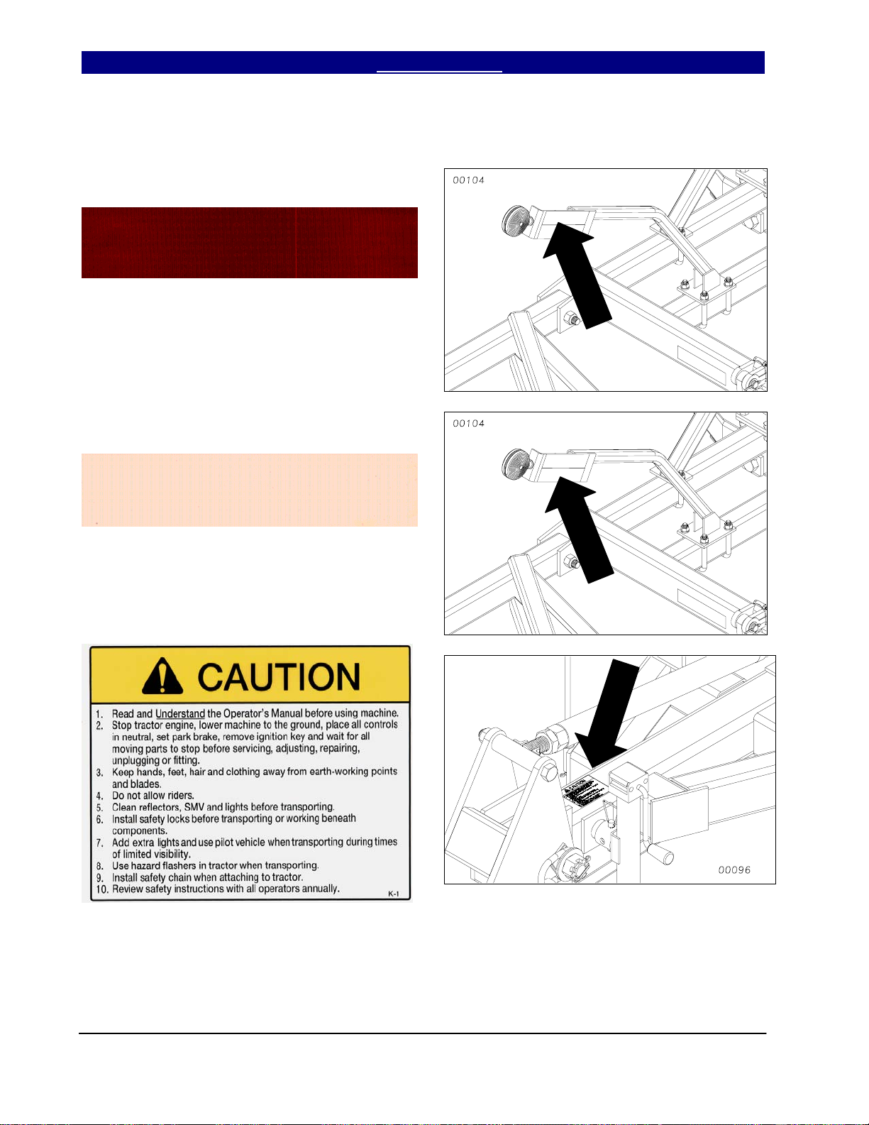
Slow Moving Vehicle Emblem
Quantity 1
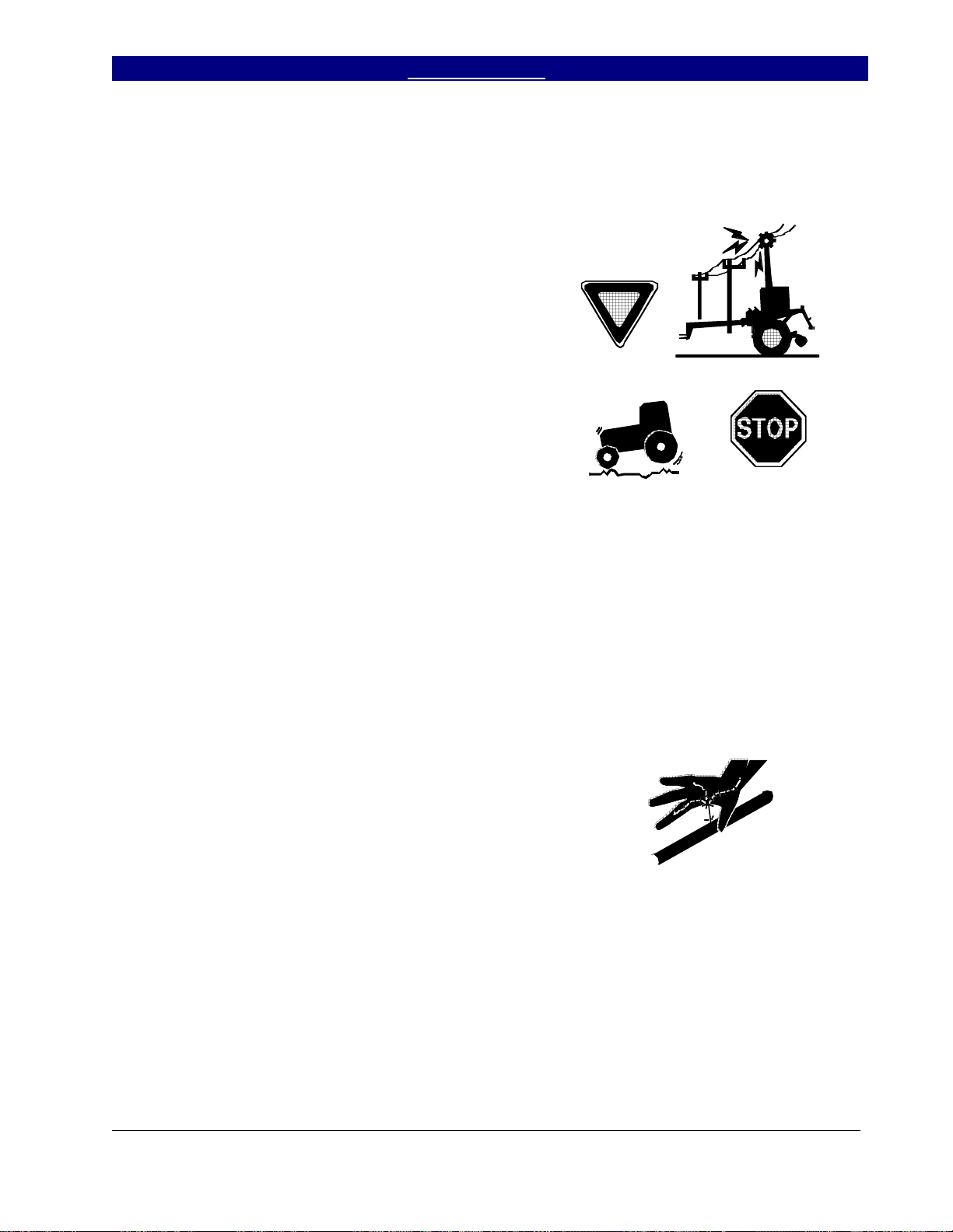
Reflector – Amber
838-615C
Quantity 6: Two on light bracket and two on
center brace bar. Two on rear of finishing
attachment (not shown), visible from side
while folded for transport.
6/15/2004 Series VII 7551-7560 Field Cultivator, Rigid Hitch 560-199M
7
Important Safety Information Table of Contents ► Great Plains Mfg., Inc.
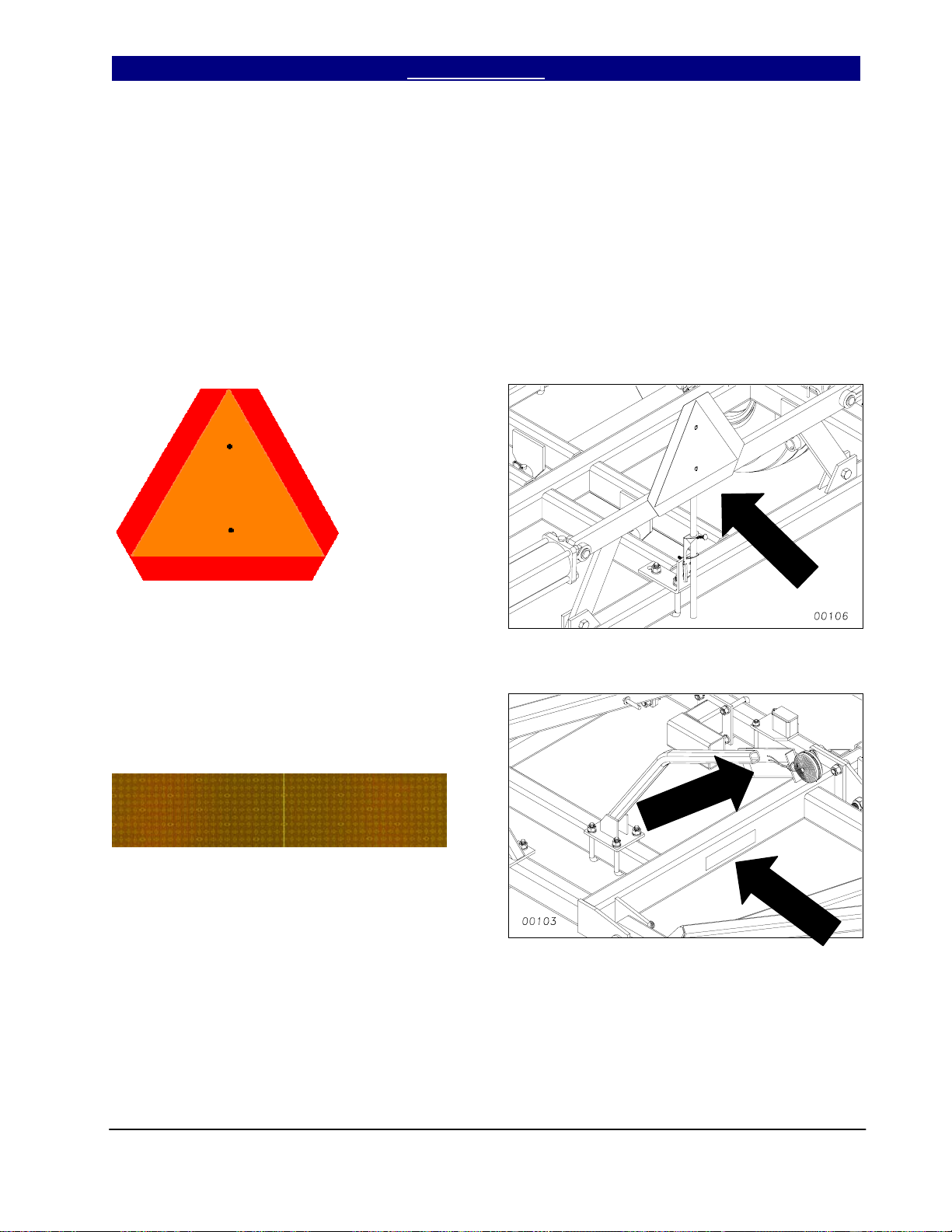
Reflector – Red
838-614C
Quantity 2
Reflector – Florescent Orange
838-603C
Quantity 2
Caution
838-598C
Quantity 1
Series VII 7551-7560 Field Cultivator, Rigid Hitch 560-199M 6/15/2004
8
Great Plains Mfg., Inc. Table of Contents ► Important Safety Information
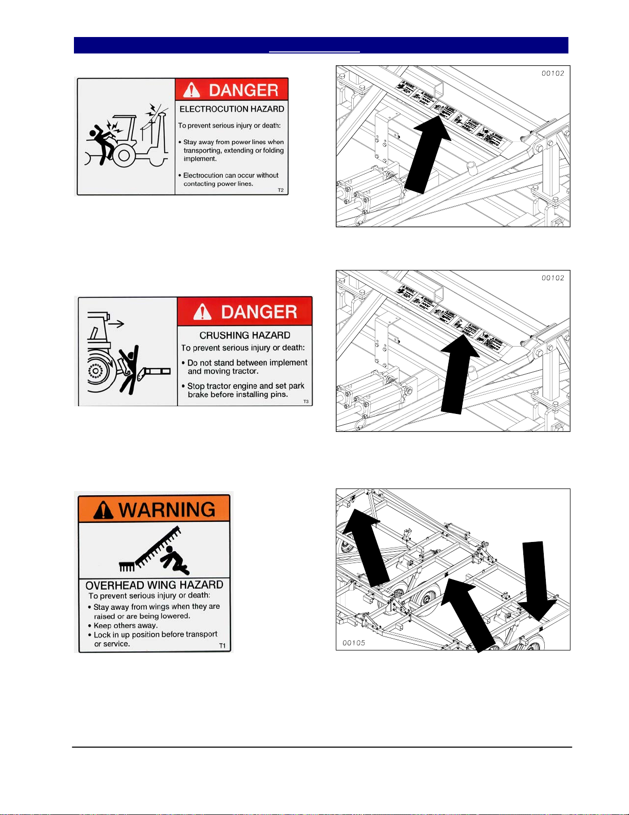
Danger Electrocution Hazard
838-599C
Quantity 1
Danger Crushing Hazard
838-600C
Quantity 1
Warning Overhead Wing Hazard
838-602C
Quantity 6
6/15/2004 Series VII 7551-7560 Field Cultivator, Rigid Hitch 560-199M
9
Important Safety Information Table of Contents ► Great Plains Mfg., Inc.
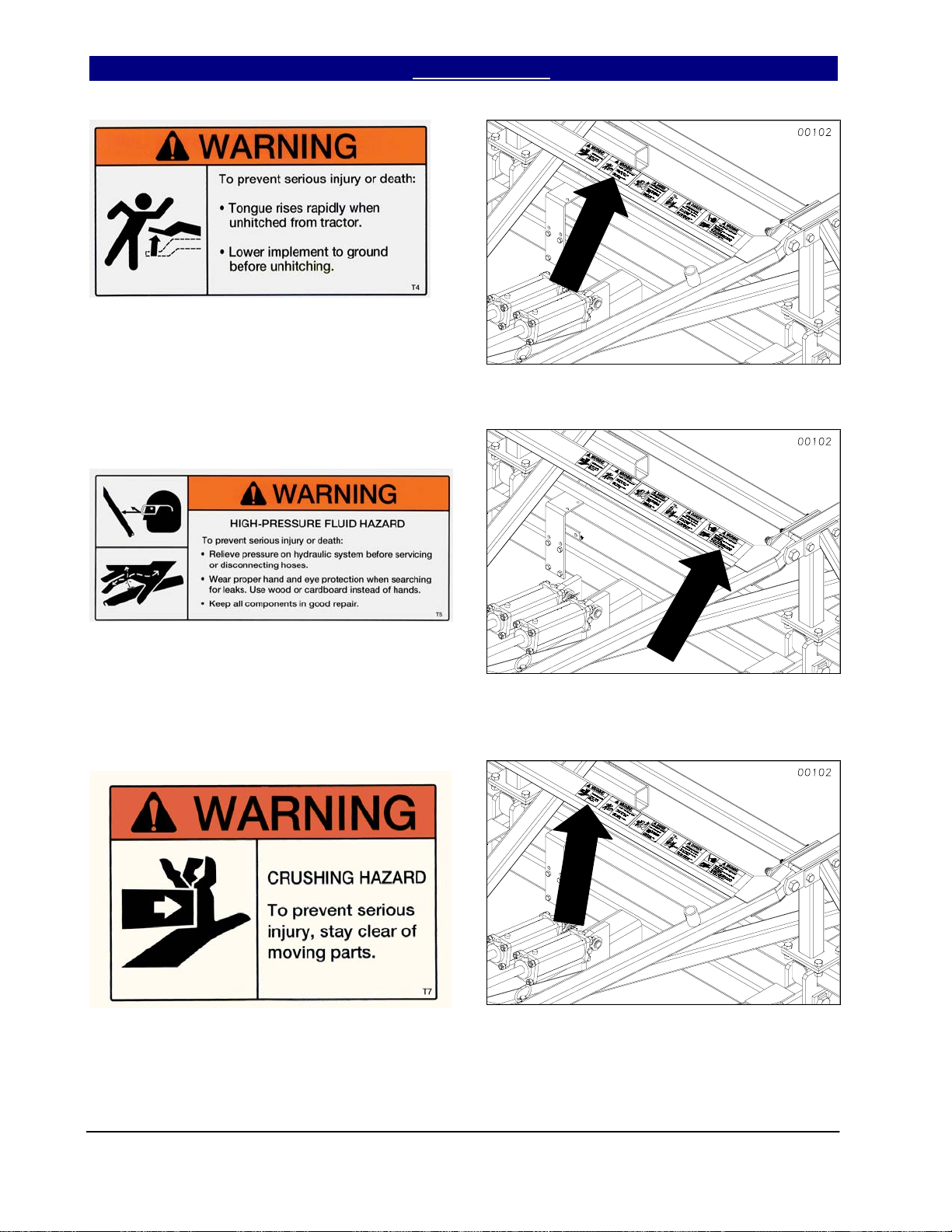
Warning Tongue Rising
838-606C
Quantity 1
Warning High Pressure Fluid Hazard
838-610C
Quantity 1
Warning Crushing Hazard
838-611C
Quantity 1
Series VII 7551-7560 Field Cultivator, Rigid Hitch 560-199M 6/15/2004
10
Great Plains Mfg., Inc. Table of Contents ► Important Safety Information
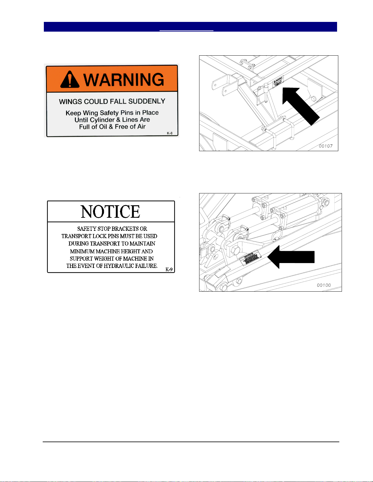
Warning Wing Falling Hazard
838-612C
Quantity 2
Notice
838-613C
Quantity 1
6/15/2004 Series VII 7551-7560 Field Cultivator, Rigid Hitch 560-199M
11

Introduction Table of Contents ► Great Plains Mfg., Inc.
Introduction
Great Plains welcomes you to its growing family of
new product owners. This implement has been
designed with care and built by skilled workers
using quality materials. Proper assembly,
maintenance and safe operation will help you get
years of satisfactory machine use from your
machine. To ease the assembly task and produce
a properly working machine, read this entire
manual before assembling or setting up new
equipment.
Description of Unit
The Series VII 7551, 7553, 7556, 7558 & 7560
Field Cultivator is a 5-section seedbed preparation
tillage tool. Working width is 51 to 60 feet. The
implement is designed for secondary field
operations to smooth, level, eliminate weeds and
incorporate chemicals. Various finishing
attachments are available to further smooth,
redistribute residue, firm soil and break clods.
Using This Manual
This manual will familiarize you with safety,
assembly, operation, adjustment, troubleshooting
and maintenance. Read this manual and follow
the recommendations to help ensure safe and
efficient operation.
The information in this manual is current at printing. Some parts may change to assure top
performance.
Definitions
The following terms are used throughout this
manual.
Right and left as used in this manual are deter-
mined by facing the direction the machine will
travel while in use unless otherwise stated.
IMPORTANT: A crucial point of information
about the preceding topic. For safe and correct
operation, read and follow the directions provided
before continuing.
NOTE: Useful information about the preceding
topic.
Owner Assistance
If customer service or repairs are needed, contact
your Great Plains dealer. They have trained
personnel, parts and service equipment specially
designed for Great Plains products.
Your machine’s parts should only be replaced with
Great Plains parts. Always use the serial and
model number when ordering parts from your
Great Plains dealer. The serial-number plate is
on the center section of the implement on the front
frame tube.
Record your implement model and serial numbers
here for quick reference.
Model Number: __________________________
Serial Number: ___________________________
Your Great Plains dealer wants you to be satisfied
with your new machine. If you do not understand
any part of this manual or are not satisfied with
the service received, please take the following
actions:
1. Discuss the matter with your dealer’s service
manager. Make sure they are aware of any
problems so they can assist you.
2. If you are still not satisfied, seek out the
dealership owner or general manager.
3. For further assistance, write to:
Product Support
Great Plains Mfg. Inc.
Service Department
PO Box 5060
Salina, KS 67402-5060
gp_web_cs@greatplainsmfg.com
(785)-823-3276
Series VII 7551-7560 Field Cultivator, Rigid Hitch 560-199M 5/15/2007
12

Great Plains Mfg., Inc. Table of Contents ► Introduction
Assembly and Setup Assistance
If you do not understand any part of this manual
or have other assembly or setup questions, assistance is available. Contact
Product Support
Great Plains Mfg. Inc., Service Department
607 Main Street
Tipton, KS 67485
Pre-Assembly Checklist
• Before assembling, read and understand “Im-
portant Safety Information,” beginning on
page 1.
• Have at least two people on hand while as-
sembling.
• Make sure assembly area is level and free of
obstructions (preferably an open concrete area).
• Have all major components.
• Have all fasteners and pins shipped with
Series VII Field Cultivator.
• IMPORTANT: If a pre-assembled part or fas-
tener is temporarily removed, remember
where it goes. Keep the parts separated.
• Have a copy of the parts manual on hand. If
unsure of proper placement or use of any part
or fastener, refer to the parts manual.
• Che c k that all working parts are moving free-
ly, bolts are tight, and cotter pins are spread.
5/15/2007 Series VII 7551-7560 Field Cultivator, Rigid Hitch 560-199M
13
Section 1: Assembly Table of Contents ► Great Plains Mfg., Inc.
Assembly
This section covers the proper assembly of the implement. The reference numbers on the
figures give you an indication of the order of assembly. For a complete breakdown of any part not
shown in this assembly section, refer to the parts manual for proper location. Refer to the Appendix
for proper bolt torque values.
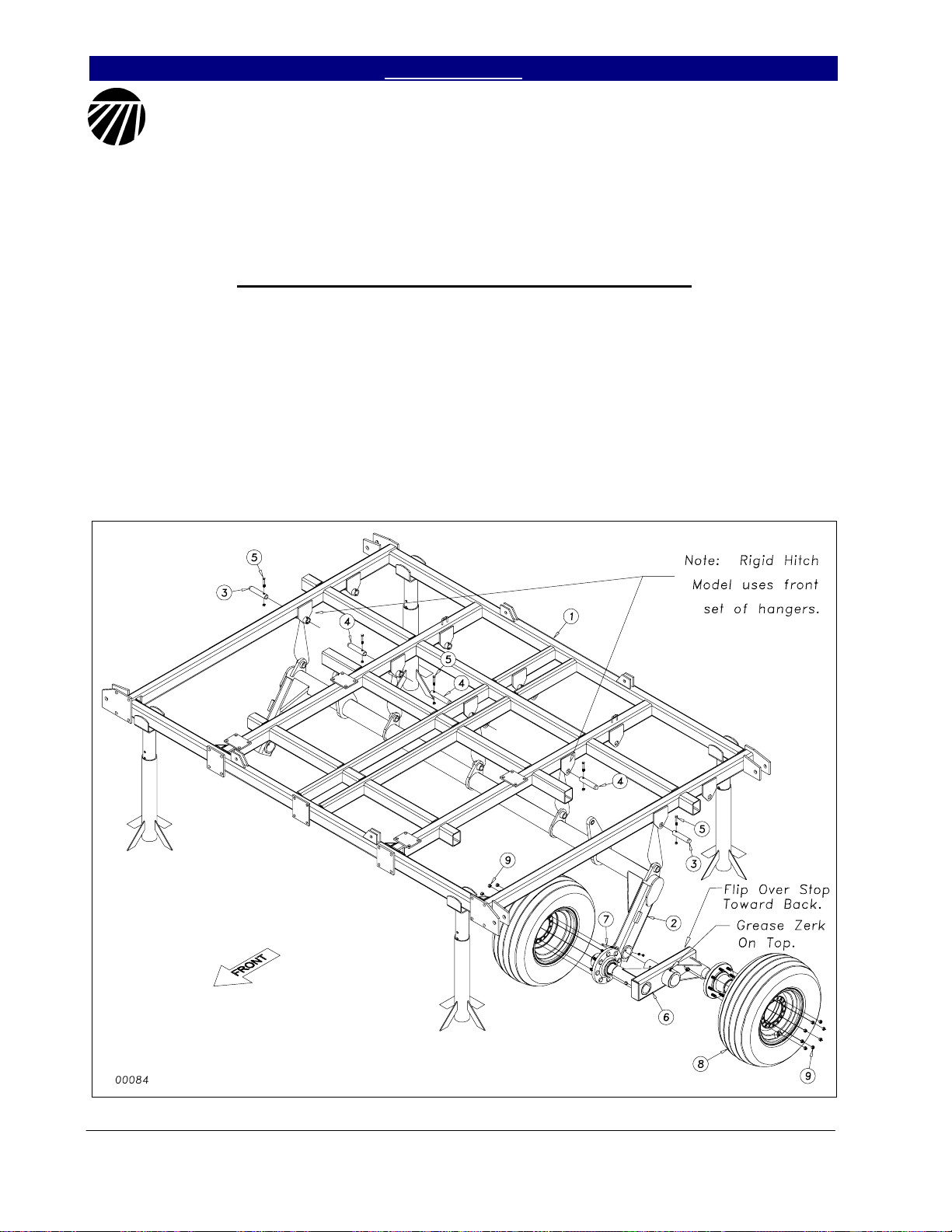
Center Torque Tube & Walking Beam Assembly
After uncrating the machine, place the
center frame (1) Figure 1, in the center of your
work area on stands. Pin the torque tube (2) to
the center frame with the 1 1/4 x 6 pins (3) and
1 1/4 x 7 pin (4), secure them with 3/8 x 2 1/4
hex bolts GR8 (5) & top lock nuts.
Slide the pivot spindle of the walking
beam assembly (6) into the sleeve at the end of
the torque tube wheel arm. Take note of the
Left and Right Walking Beam Assembly (6).
The Flip Over Stop goes Toward Rear and
Grease Zerk up. It is a good idea to put some
form of anti-seize on the spindle before you
insert it. Line up the hole in the spindle with
the hole in the sleeve and secure with 5/16 x 4
1/2 hex bolt (7) with lock washer and hex nut.
When both walking beams have been
installed, bolt on the 11L x 15, F-ply tires (8)
with the 5/8” lug nuts (9).
Figure 1
Series VII 7551-7560 Field Cultivator, Rigid Hitch 560-199M 2/01/2005
5/22/2008
14
Great Plains Mfg., Inc. Table of Contents ► Section 1: Assembly
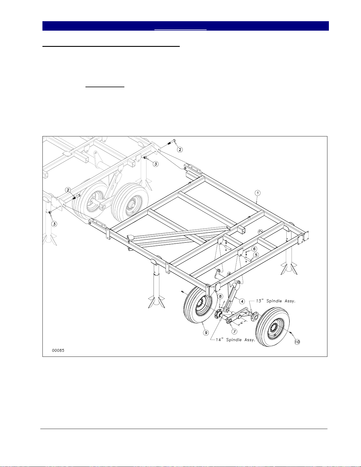
Inside Wing and Wheel Arm Assembly
Bolt the inside wing frames (1) Figure
2, to the center frame with two 1 x 6 hex bolts
(2) with nylon lock nuts (3). Draw the nuts
down tight but do not torque
Once the wings are attached, insert the
wheel arm bracket (4) into the wing frame
hangers and secure it just as you did on the
center with 1 1/4 x 6 pins (5). Secure the pins
with 3/8 x 2 1/4 GR8 hex bolts (6) & top lock
nuts.
.
(7) as shown in Figure 2 with the long 14”
spindle toward the front. Use anti-seize
material on spindle. Secure the pivot spindle in
the sleeve with the 5/16 x 3 clevis pin (8) and
1/8 x 1 cotter.
place with the 1/2 x 1 1/4 lug bolts (10).
Install the wing walking beam assembly
Bolt the 9.5L x 15, 8-ply tires (9) in
Figure 2
2/01/2005 Series VII 7551-7560 Field Cultivator, Rigid Hitch 560-199M
5/222008
15
Section 1: Assembly Table of Contents ► Great Plains Mfg., Inc.
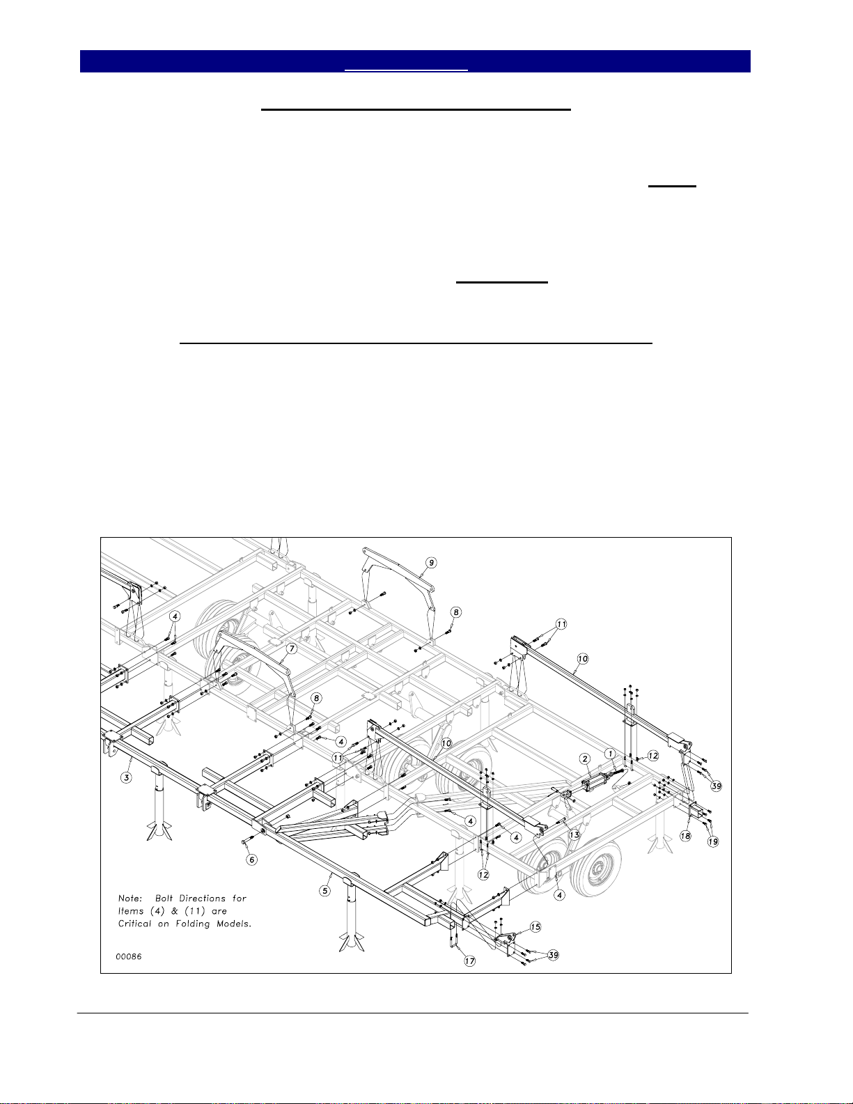
Brace Bar and Wing Brace Assembly
Install the 1 x 7 1/2 eye bolt (1) Figure
3, in the mounting bracket at the back of the
wing with a 1” jam nut on each side of the
bracket. Install the 3 1/4 x 8 rephasing wing
cylinder (2) between the eyebolt and the lever
on the wheel bracket. Secure the cylinder with
1 x 3 clevis pins, 1” machine washer and 3/16 x
2 cotter pin.
of the center frame with 3/4 x 2 hex bolts (4)
with lock washers and hex nuts. Do not tighten
bolts. Bolt the wing brace (5) to the front of the
wing with 3/4 x 2 hex bolts (4) with lock
washer and hex nuts. Use a 1 x 6 hex bolt (6)
and nylon lock nut in the hinge. Draw nut tight
but do not torque. Tighten all other bolts
evenly to prevent bind at hinge.
Bolt the center brace bar (3) to the front
Rocker/Fold Bracket and Center Fold Bracket Assembly
Bolt the front and rear center fold
brackets (7 & 9), Figure 3, to the center frame
with two 3/4 x 2 1/2 hex bolts (8) with lock
washer and hex nuts.
Bolt the rocker/fold brackets (10) to the
wing using two 3/4 x 2 1/2 hex bolts (11) with
lock washers and hex nuts, along with two 5/8
x 3 x 5 1/2 u-bolts (12) with lock washer and
hex nuts. The front bracket uses a 3/4 x 5 bolt
(13) to attach the outer end. The rear bracket
uses four 5/8 x 2 bolts (14) with lock washers
and hex nuts to attach the outer end. Bolt the
inside hinge (15) to the wing brace using 5/8 x
2 bolts (16) and one 5/8 x 3 x 5 1/2 u-bolt (17)
with lock washers and hex nuts. Bolt the 5”
stub (18) to the wing frame using 5/8 x 1 1/2
bolts (19) with lock washers and hex nuts.
Figure 3
Series VII 7551-7560 Field Cultivator, Rigid Hitch 560-199M 2/01/2005
5/5/2008
5/22/2008
16
Great Plains Mfg., Inc. Table of Contents ► Section 1: Assembly
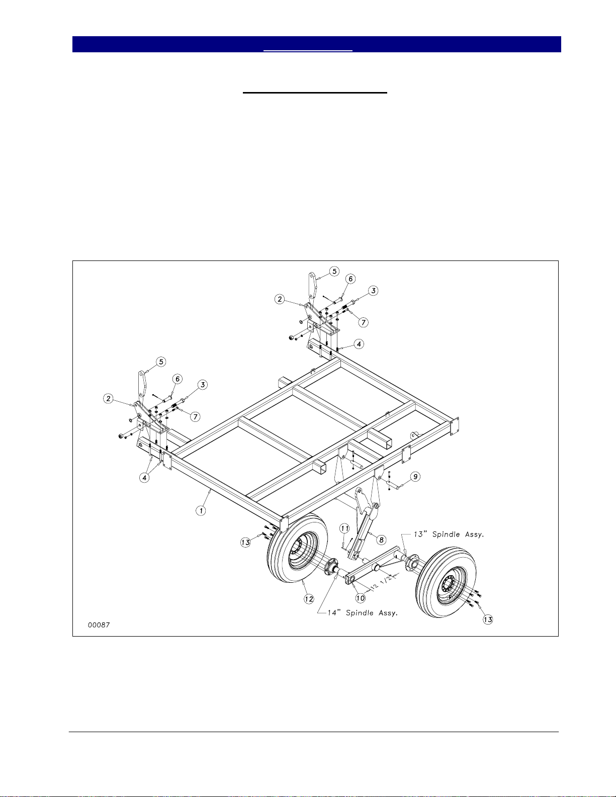
Outside Wing Assembly
Assemble the outside wing (1) by
attaching the outside hinges (2) to the wing
with 1 x 6 hex bolt (3) and 5/8 x 3 x 5 1/2 ubolts (4) as shown in Figure 4. Use a nylon
lock nut on the 1 x 6 hex bolt (3) with lock
washers and hex nuts on the u-bolt. Attach the
180 degree rocker (5), bulge side out, with the
1 x 3 headed pin (6), 1” machine washer and
3/16 x 2 cotter pin. Insert a 1/2 x 2 1/2 hex bolt
(7) in the outside hinge and secure with lock
washer and hex nut.
as we did the inside ones, using the 1 1/4 x 6
pins (9) and 3/8 x 2 1/4 GR8 hex bolts & top
lock nuts. Slide the walking beam assembly
(10) into the wheel bracket sleeve as shown in
Figure 4. Again, it is recommended to use
some form of anti-seize product on the spindle.
Note that the longer 14” long spindle assembly
goes to the front. Bolt on the 9.5L x 15 tire and
wheels (12) with the 1/2 x 1 1/4 lug bolts (13).
Attach the outside wheel bracket (8) just
Figure 4
2/01/2005 Series VII 7551-7560 Field Cultivator, Rigid Hitch 560-199M
5/22/2008
17
 Loading...