

Operator’s Manual
Series VII 6326, 6328, 6536, 6542, 7333, 7336, 7548 & 7552
Discovator (Disc & Coulter)
Manufacturing, Inc.
Read the operator’s manual entirely. When you see this symbol, the subsequent
!
instructions and warnings are serious - follow without exception. Your life and the
lives of others depend on it
Cover illustration may show optional equipment not supplied with standard unit.
©Copyright 2004 Printed 8/11/2008 550-221M

Great Plains Mfg., Inc. First Page ► Table of Contents
Table of Contents
Important Safety Information .......................... 1
Safety Rules................................................... 6
Safety Decals ................................................ 7
Introduction ........................................................ 12
Description of Unit........................................ 12
Using this Manual ........................................12
Definitions.............................................. 12
Owner Assistance .......................................... 12
Assembly and Setup Assistance .................... 13
Product Support .....................................13
Pre-Assembly Checklist ........................ 13
Section 1 Assembly ............................................. 14
Center Frame, Torque Tube & Walking
Beam Assembly ....................................... 14
Inside Wing and Wheel Arm Assembly .......15
Brace Bar, Wing Brace & Rocker/Fold
Bracket Assembly .................................... 16
Outside Wing Assembly ............................... 17
Connecting Outside Wing and Wing Brace
Assembly ................................................. 18
Center Gang & Gang Hanger Assembly. ...... 19
Center Truss, Hitch and Strut Assembly ...... 20
Hitch Tongue, Side Plate and Level Bar
Assembly ................................................. 21
Center Lift Cylinder, Rest Pads and
Hydraulic Valves Assembly ................... 22
Fold Cylinders, Rocker Arm and 3” Rollers
Assembly ................................................ 23
Center Wing Stop and Outside Wing Stop
Assembly ................................................ 24
Front Gauge Wheel Assembly .....................25
Hydraulic Gauge Wheel Assembly .............. 26
Completing Setup ......................................... 27
Section 2 Hydraulics .......................................... 28
Hydraulic Layout: 6326, 6328, 7333, 7336... 28
Hydraulic Layout: 6536................................. 30
Hydraulic Layout: 6542, 7548 & 7552 .........32
Hydraulic Gang Layout ................................ 34
Section 3 Replacement Parts .............................36
Magnum Shank Assembly ............................ 36
K-Flex Shank Assembly ............................... 38
Disc Gang Assembly .................................... 40
Disc Gang Identification .............................. 42
Coulter Gang Assembly ...............................44
Coulter Gang Identification .......................... 46
Center Walking Beam 6300DV (All S/N)
& 7300DV (S/N 1226DD-)...................... 48
Center Walking Beam 6500DV
(S/N 1329DD+) ....................................... 50
Center Walking Beam 7333DV
(S/N 1227DD+)........................................ 52
Center Walking Beam 7500DV ................... 54
Wing Walking Beam Assembly ................... 56
6536 & 6542 Outside Wing Transport
(Standard Hub) ........................................ 58
(Optional Heavy Hub) ............................. 60
8 & 6-Bolt Heavy Hub & Spindle Assy.
(S/N 1329DD+) ....................................... 62
6-Bolt Hub & Spindle Assembly ................. 64
Front Gauge Wheel Assembly ..................... 66
Hydraulic Gauge Wheel Assembly .............. 68
Section 4 Machine Layout ................................. 70
6326D Machine Layout, Disc ...................... 70
6326C Machine Layout, Coulter .................. 71
6328D Machine Layout, Disc ...................... 72
6328C Machine Layout, Coulter .................. 73
6536D Machine Layout, Disc
Single Fold (S/N 1329DD+) ................... 74
Double Fold (S/N 1329DD+) .................. 76
6536C Machine Layout, Coulter
Single Fold (S/N 1329DD+) ................... 78
Double Fold (S/N 1329DD+) .................. 80
6542D Machine Layout, Disc
(S/N 1329DD+) ....................................... 82
6542C Machine Layout, Coulter
(S/N 1329DD+) ....................................... 84
7333D Machine Layout, Disc
(S/N 1227DD+) ....................................... 86
7333C Machine Layout, Coulter
(S/N 1227DD+) ....................................... 87
7336D Machine Layout, Disc ...................... 88
7336C Machine Layout, Coulter .................. 89
7548D Machine Layout, Disc ...................... 90
7548C Machine Layout, Coulter .................. 92
7552D Machine Layout, Disc ...................... 94
7552C Machine Layout, Coulter .................. 96
1/19/2006 Series VII 6326-7552 Discovator 550-221M

Table of Contents Table of Contents ► Great Plains Mfg., Inc.
Section 5 Operating and Maintenance..............98
Prior to Going to the Field ............................ 98
First Time Machine Setup and Adjustments 98
General Operating Instructions and
In-Field Adjustments ............................... 100
Maintenance and Lubrication ....................... 102
Section 6 Specification and Capacities ............. 103
Appendix ............................................................. 104
Torque Values for Common Bolt Sizes ....... 104
Tire Inflation Chart ...................................... 104
Warranty ....................................................... 105
Series VII 6326-7552 Discovator 550-221M 1/19/2006

Great Plains Mfg., Inc. First Page ► Table of Contents
©
Copyright 2004 All rights Reserved
Great Plains Manufacturing, Inc. provides this publication “as is” without warranty of any kind, either expressed or implied. While every precaution has been
taken in the preparation of this manual, Great Plains Manufacturing, Inc. assumes no responsibility for errors or omissions. Neither is any liability assumed for
damages resulting from the use of the information contained herein. Great Plains Manufacturing, Inc. reserves the right to revise and improve its products as it
sees fit. This publication describes the state of this product at the time of its publication, and may not reflect the product in the future.
The following are trademarks of Great Plains Mfg., Inc.: Application Systems, Ausherman, Land Pride, Great Plains
All other brands and product names are trademarks or registered trademarks of their respective holders.
Great Plains Manufacturing, Incorporated Trademarks
Printed in the United States of America.
1/19/2006 Series VII 6326-7552 Discovator 550-221M
Great Plains Mfg., Inc. Table of Contents ► Important Safety Information
R
Important Safety Information
Look for Safety Symbol
The SAFETY ALERT SYMBOL indicates there is
a potential hazard to personal safety involved
and extra safety precaution must be taken.
When you see this symbol, be alert and carefully
read the message that follows it. In addition to
design and configuration of equipment, hazard
control and accident prevention are dependent
upon the awareness, concern, prudence and
proper training of personnel involved in the
operation, transport, maintenance and storage of
equipment.
Be Aware of Signal Words
!
Signal words designate a degree or level of hazard seriousness.
DANGER indicates an imminently hazardous situation, which, if not avoided, will result in death
or serious injury. This signal word is limited to
the most extreme situations, typically for
machine components that, for functional
purposes, cannot be guarded.
WARNING indicates a potentially hazardous
situation, which, if not avoided, could result in
death or serious injury, and includes hazards
that are exposed when guards are removed. It
may also be used to alert against unsafe
practices.
CAUTION indicates a potentially hazardous situation, which, if not avoided, may result in minor
or moderate injury. It may also be used to alert
against unsafe practices.
!
DANGE
!
WARNING
!
CAUTION
3/31/2004 Series VII 6326-7552 Discovator 550-221M
1
Important Safety Information Table of Contents ► Great Plains Mfg., Inc.
Be Familiar with Safety Decals
• Read and understand “Safety Decals,” page
7, thoroughly.
• Read all instructions noted on the decals.
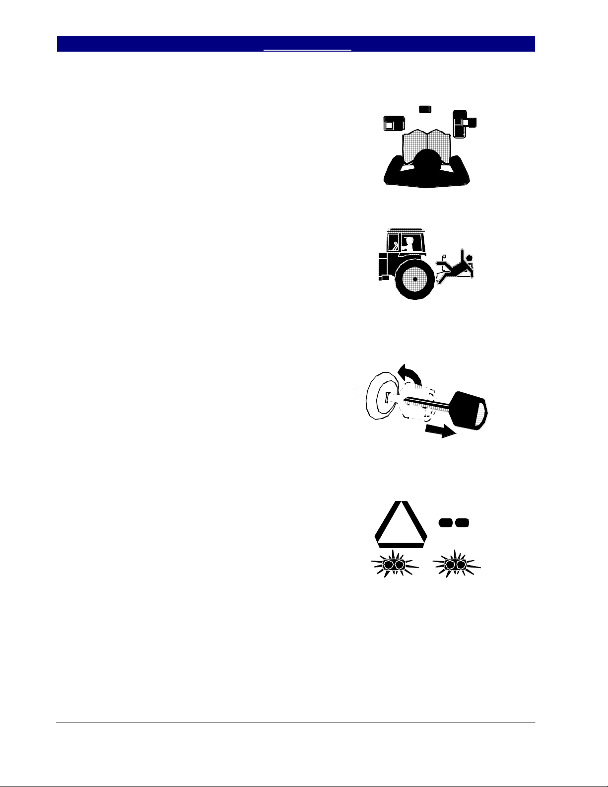
Keep Riders Off Machinery
• Riders obstruct the operator’s view. Riders
could be struck by foreign objects or thrown
from the machine.
• Never allow children to operate equipment.
• Keep all bystanders away from machine dur-
ing operation.
Shutdown and Storage
• Lower Series VII Discovator, put tractor in
park, turn off engine, and remove the key.
• Secure Series VII Discovator using blocks
and supports provided.
• Detach and store Series VII Discovator in an
area where children normally do not play.
Use Safety Lights and Devices
• Slow-moving tractors and towed implements
can create a hazard when driven on public
roads. They are difficult to see, especially at
night.
• Use flashing warning lights and turn signals
whenever driving on public roads.
• Use lights and devices provided with implement.
OFF
Series VII 6326-7552 Discovator 550-221M 3/31/2004
2
Great Plains Mfg., Inc. Table of Contents ► Important Safety Information
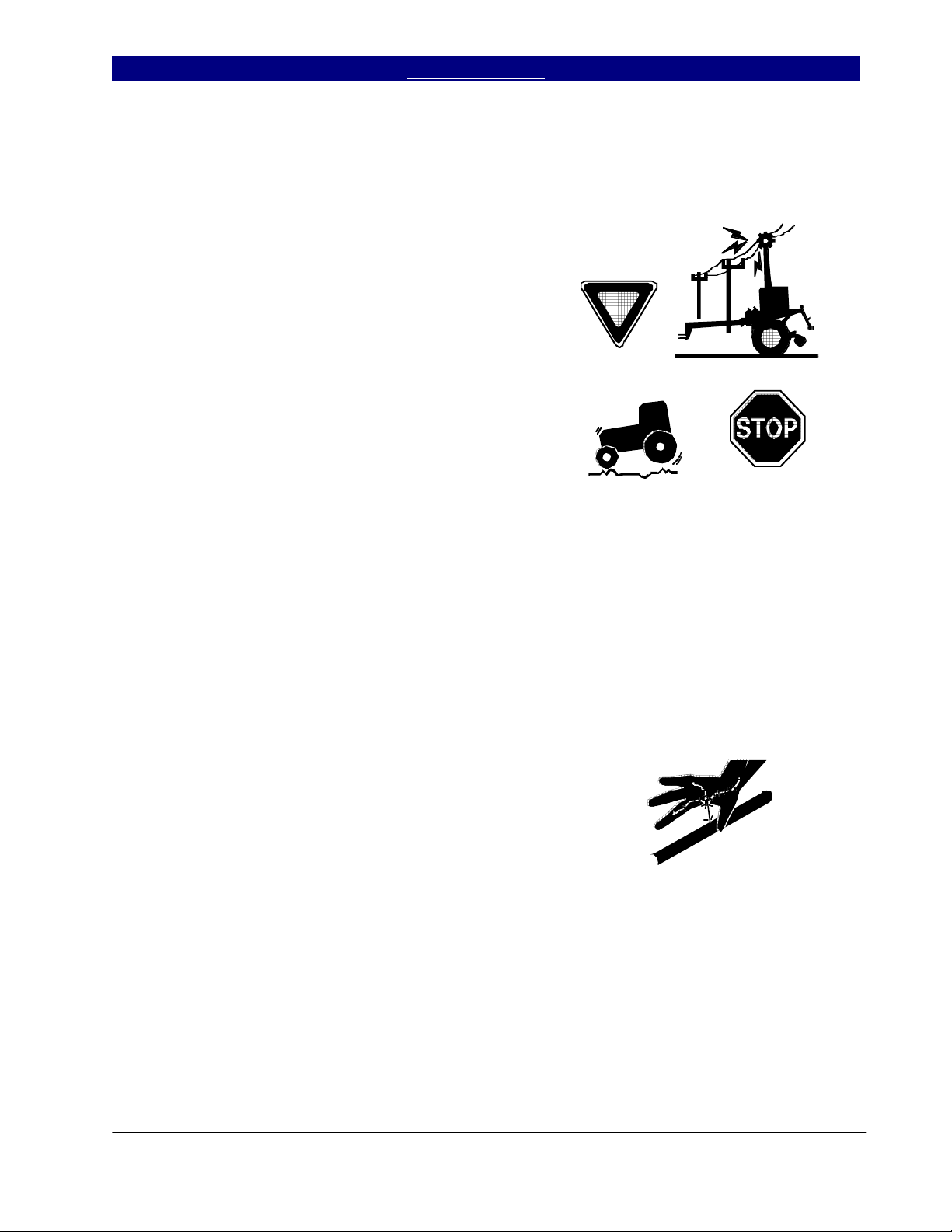
Transport Machinery Safely
Maximum transport speed for implement is 20
mph. Some rough terrains require a slower
speed. Sudden braking can cause a towed load
to swerve and upset.
• Do not exceed 20 mph. Never travel at a
speed which does not allow adequate
control of steering and stopping. Reduce
speed if towed load is not equipped with
brakes.
• Comply with state and local laws.
• Do not tow an implement that, when fully
loaded, weighs more than 1.5 times the
weight of towing vehicle.
• Carry reflectors or flags to mark tractor and
implement in case of breakdown on the
road.
• Keep clear of overhead power lines and
other obstructions when transporting. Refer
to transport dimensions under
“Specifications and Capacities,” page 103.
• Do not fold or unfold the wings while the
tractor is moving.
Avoid High Pressure Fluids
Escaping fluid under pressure can penetrate the
skin, causing serious injury.
• Avoid the hazard by relieving pressure
before disconnecting hydraulic lines.
• Use a piece of paper or cardboard, NOT
BODY PARTS, to check for suspected
leaks.
• Wear protective gloves and safety glasses
or goggles when working with hydraulic
systems.
• If an accident occurs, see a doctor immediately. Any fluid injected into the skin must be
surgically removed within a few hours or
gangrene may result.
3/31/2004 Series VII 6326-7552 Discovator 550-221M
1/19/2006
3

Important Safety Information Table of Contents ► Great Plains Mfg., Inc.
Practice Safe Maintenance
• Understand procedure before doing work.
Use proper tools and equipment. Refer to
this manual for additional information.
• Work in a clean, dry area.
• Lower the Series VII Discovator, put tractor
in park, turn off engine, and remove key
before performing maintenance.
• Make sure all moving parts have stopped
and all system pressure is relieved.
• Inspect all parts. Make sure parts are in
good condition and installed properly.
• Remove buildup of grease, oil or debris.
• Remove all tools and unused parts from
Series VII Discovator before operation.
Prepare for Emergencies
• Be prepared if a fire starts.
• Keep a first aid kit and fire extinguisher
handy.
• Keep emergency numbers for doctor, ambulance, hospital and fire department near
phone.
Wear Protective Equipment
• Wear protective clothing and equipment.
• Wear clothing and equipment appropriate for
the job. Avoid loose-fitting clothing.
• Because prolonged exposure to loud noise
can cause hearing impairment or hearing
loss, wear suitable hearing protection such
as earmuffs or earplugs.
• Because operating equipment safely
requires your full attention, avoid wearing
radio headphones while operating
machinery.
911
Series VII 6326-7552 Discovator 550-221M 3/31/2004
4
Great Plains Mfg., Inc. Table of Contents ► Important Safety Information
Handle Chemicals Properly
• Agricultural chemicals can be dangerous.
Improper use can seriously injure persons,
animals, plants, soil and property.
• Read and follow chemical manufacturer’s
instructions.
• Wear protective clothing.
• Handle all chemicals with care.
• Avoid inhaling smoke from any type of
chemical fire.
• Store or dispose of unused chemicals as
specified by chemical manufacturer.
Use A Safety Chain
• Use a safety chain to help control drawn
machinery should it separate from tractor
drawbar.
• Use a chain with a strength rating equal to or
greater than the gross weight of towed
machinery.
• Attach chain to tractor drawbar support or
other specified anchor location. Allow only
enough slack in chain to permit turning.
• Replace chain if any links or end fittings are
broken, stretched or damaged.
• Do not use safety chain for towing.
Tire Safety
• Tire changing can be dangerous and should
be performed by trained personnel using
correct tools and equipment.
• When inflating tires, use a clip-on chuck and
extension hose long enough to you to stand
to one side–not in front of or over tire
assembly. Use a safety cage if available.
• When removing and installing wheels, use
wheel-handling equipment adequate for
weight involved.
3/31/2004 Series VII 6326-7552 Discovator 550-221M
5

Important Safety Information Table of Contents ► Great Plains Mfg., Inc.
Safety Rules
• Thoroughly read and understand the
instructions in this manual before operation.
Read all instructions noted on the safety
decals.
• Be familiar with all Series VII Discovator
functions.
• Operate machinery from the driver’s seat
only.
• Do not leave Series VII Discovator unattended with tractor engine running.
• Do not transport Series VII Discovator
the transport pins and all wing locks are
installed.
• Limit transport speed to 20 m.p.h.
• Know the transport height of your unit and be
extremely careful of overhead electrical and
telephone lines when transporting the unit.
• Know the transport width of your machine and
the width of bridges, etc… on the transport
route.
• Make sure that no one is near the machine
during field operation and folding or unfolding
of wing sections.
• Prior to removing any lift cylinders from the
machine, lower implement to the ground, shut
off the tractor and release the pressure in the
lines.
• Do not depend on cylinders to hold the weight
of machine during storage; use the transport
locks.
• Do not walk or stand on any part of the
machine. Never allow anyone to ride on the
Series VII Discovator.
• Use extreme care when hitching or unhitching
the machine from the tractor. In some
situations with a heavy finishing attachment,
the machine may tip backward causing the
hitch to rise rapidly.
• Never stand with feet under any part of the
machine.
until
• Never allow anyone to walk between the
tractor and Series VII Discovator while
machine is in operation.
• Keep hands and feet away from turbo blades.
They are quite sharp.
• Any moving piece of equipment is potentially
dangerous. Do not operate until you are
absolutely sure the area is clear of children,
pets and irresponsible persons.
• Escaping hydraulic fluid under pressure can
have sufficient force to penetrate the skin,
causing serious injury. To prevent injury
when working with hydraulics, follow the
instructions on page 3.
• Before transporting the unit on public roads,
check to make sure the safety reflectors are
clean and visible, and not missing or
damaged. Turn on tractor warning lights
when transporting.
• Make sure all safety signs are clean, readable
and not damaged. Contact Great Plains Mfg.
for free replacements if necessary.
Series VII 6326-7552 Discovator 550-221M 3/31/2004
6
Great Plains Mfg., Inc. Table of Contents ► Important Safety Information
Safety Decals
Your implement comes equipped with all safety
decals in place. They were designed to help you
safely operate your implement.
• Read and follow decal directions.
• Keep all safety decals clean and legible.
• Replace all damaged or missing decals. Order
new decals from your Great Plains dealer.
Refer to this section for proper placement.
• When ordering new parts or components, also
request corresponding safety decals.
• To install new decals:
1. Clean the area on which the decal is to be
placed.
2. Peel backing from decal. Press firmly on
surface, being careful not to cause air
bubbles under decal.
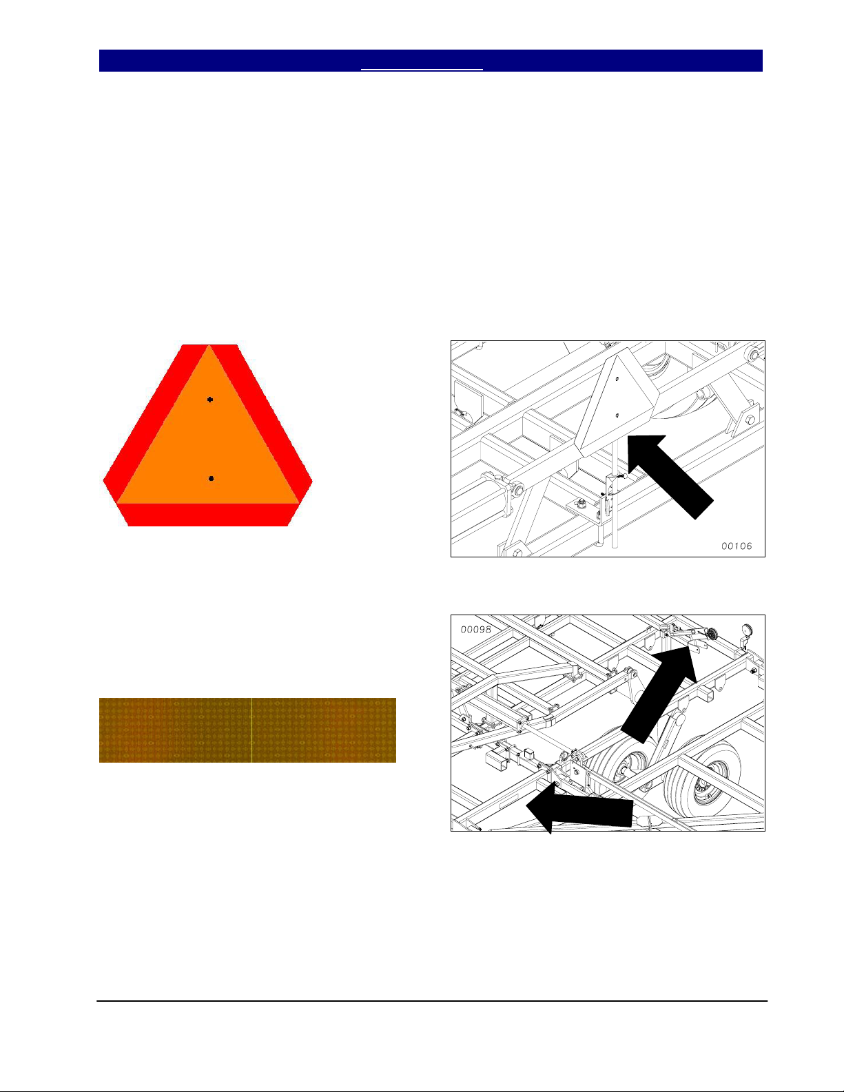
Slow Moving Vehicle Emblem
Quantity 1
Reflector – Amber
838-615C
Quantity 6: Two on light bracket and two on
center brace bar. Two on rear of finishing
attachment (not shown), visible from side
while folded for transport.
3/31/2004 Series VII 6326-7552 Discovator 550-221M
7
Important Safety Information Table of Contents ► Great Plains Mfg., Inc.
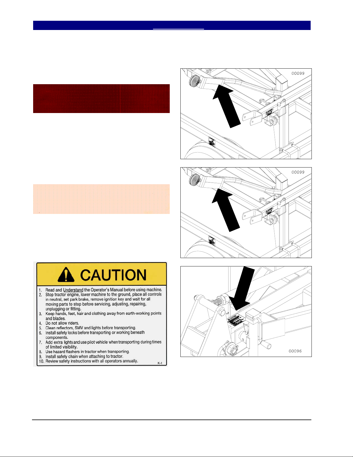
Reflector – Red
838-614C
Quantity 2:
Reflector – Florescent Orange
838-603C
Quantity 2:
Caution
838-598C
Quantity 1
Series VII 6326-7552 Discovator 550-221M 3/31/2004
8
Great Plains Mfg., Inc. Table of Contents ► Important Safety Information
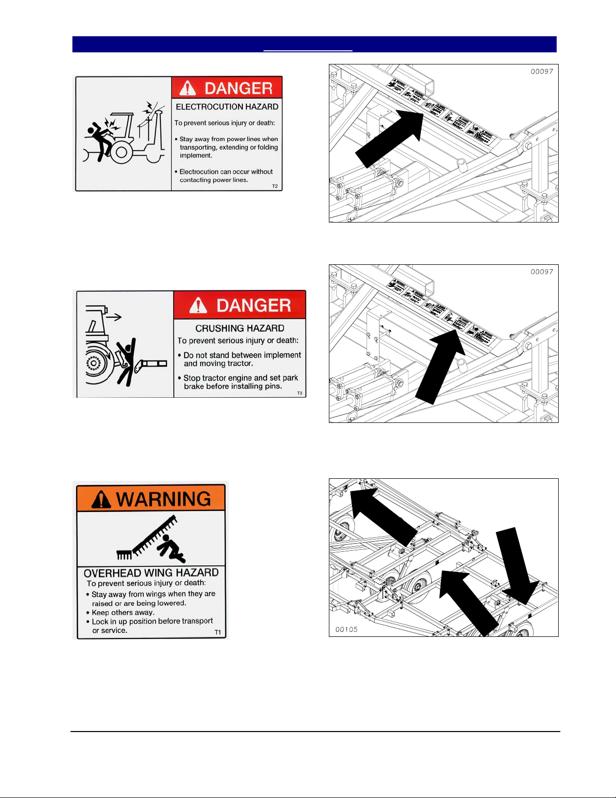
Danger Electrocution Hazard
838-599C
Quantity 1
Danger Crushing Hazard
838-600C
Quantity 1
Warning Overhead Wing Hazard
838-602C
Quantity 4: 6326, 6328, 7333 & 7336
Quantity 6: 6536, 6542, 7548 & 7552
3/31/2004 Series VII 6326-7552 Discovator 550-221M
9
Important Safety Information Table of Contents ► Great Plains Mfg., Inc.
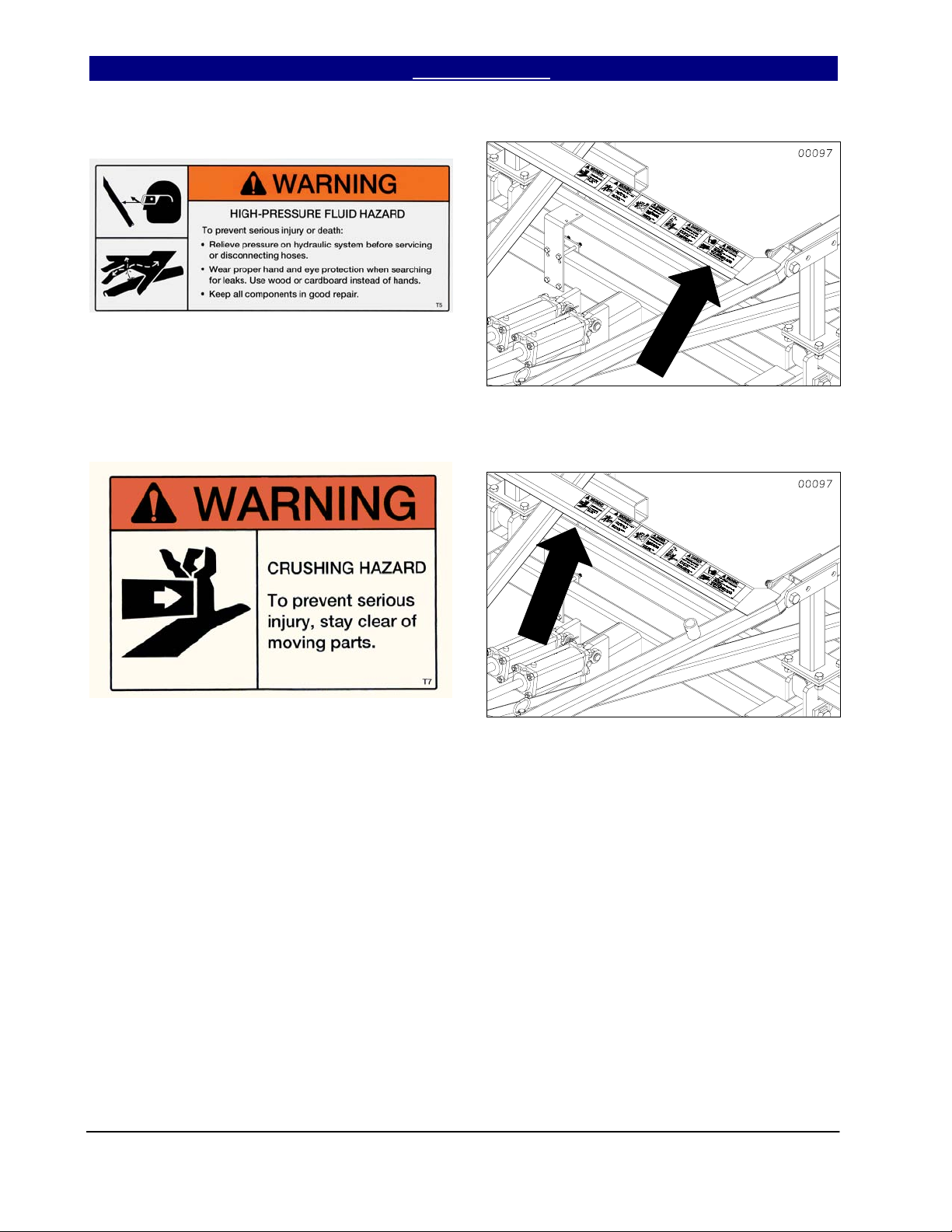
Warning High Pressure Fluid Hazard
838-610C
Quantity 1
Warning Crushing Hazard
838-611C
Quantity 1
Series VII 6326-7552 Discovator 550-221M 3/31/2004
10
Great Plains Mfg., Inc. Table of Contents ► Important Safety Information
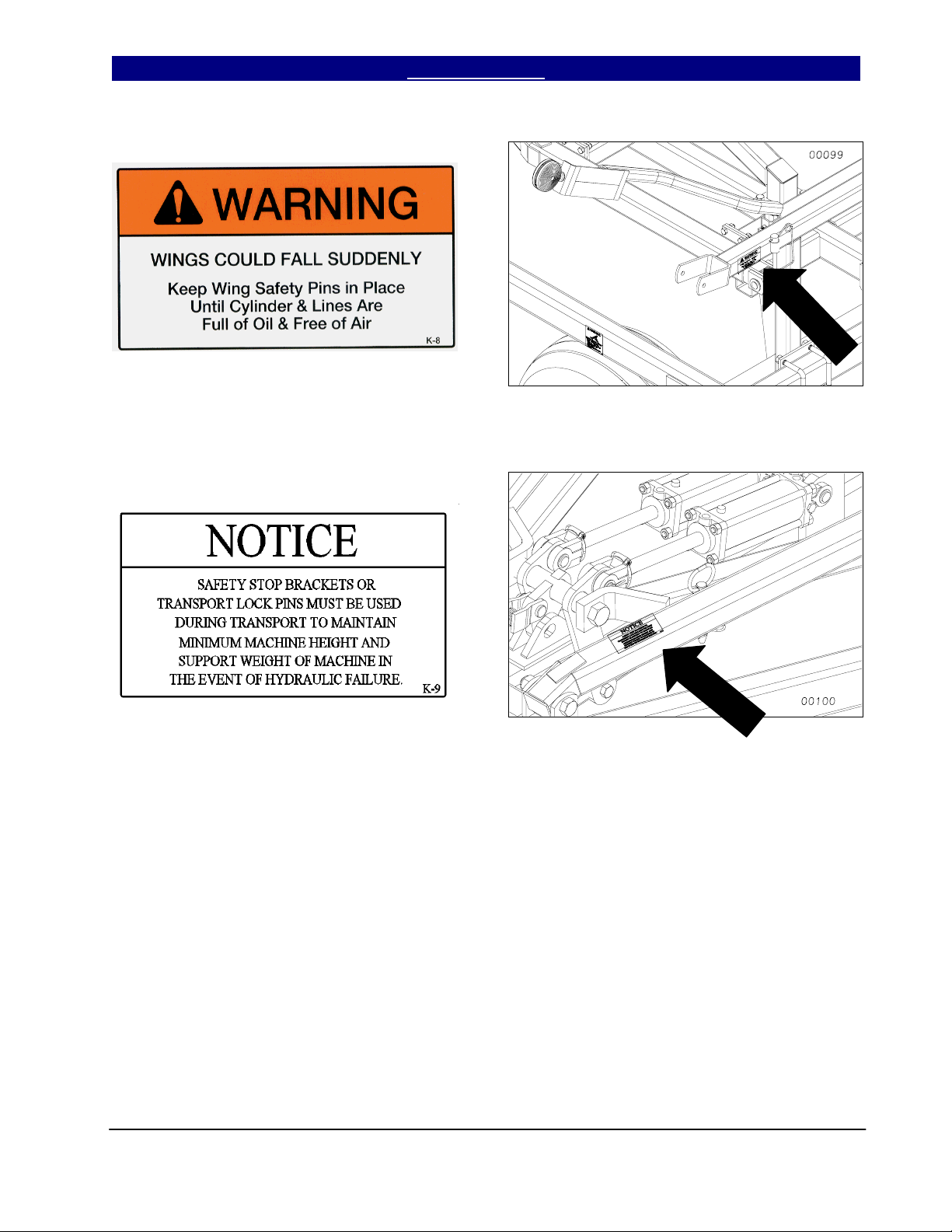
Warning Wing Falling Hazard
838-612C
Quantity 2
Notice
838-613C
Quantity 1
3/31/2004 Series VII 6326-7552 Discovator 550-221M
11

Introduction Table of Contents ► Great Plains Mfg., Inc.
Introduction
Great Plains welcomes you to its growing family of
new product owners. This implement has been
designed with care and built by skilled workers
using quality materials. Proper assembly,
maintenance and safe operation will help you get
years of satisfactory machine use from your
machine. To ease the assembly task and produce
a properly working machine, read this entire
manual before assembling or setting up new
equipment.
Description of Unit
The Series VII 6326-7552 Discovator is a three or
five-section field finishing, one-pass tillage tool.
Working width ranges from 26 to 52 feet. The
implement is designed to combine discing/slicing,
cultivating, harrowing and herbicide incorporation
in a single pass. Various finishing attachments
are available to customize your tillage and residue
requirements for your operation.
Using This Manual
This manual will familiarize you with safety,
assembly, operation, adjustment, troubleshooting
and maintenance. Read this manual and follow
the recommendations to help ensure safe and
efficient operation.
The information in this manual is current at printing. Some parts may change to assure top
performance.
Definitions
The following terms are used throughout this
manual.
Right and left as used in this manual are deter-
mined by facing the direction the machine will
travel while in use unless otherwise stated.
IMPORTANT: A crucial point of information
about the preceding topic. For safe and correct
operation, read and follow the directions provided
before continuing.
NOTE: Useful information about the preceding
topic.
Owner Assistance
If customer service or repairs are needed, contact
your Great Plains dealer. They have trained
personnel, parts and service equipment specially
designed for Great Plains products.
Your machine’s parts should only be replaced with
Great Plains parts. Always use the serial and
model number when ordering parts from your
Great Plains dealer. The serial-number plate is
on the center section of the implement on the front
frame tube.
Record your implement model and serial numbers
here for quick reference.
Model Number: __________________________
Serial Number: ___________________________
Your Great Plains dealer wants you to be satisfied
with your new machine. If you do not understand
any part of this manual or are not satisfied with
the service received, please take the following
actions:
1. Discuss the matter with your dealer’s service
manager. Make sure they are aware of any
problems so they can assist you.
2. If you are still not satisfied, seek out the
dealership owner or general manager.
3. For further assistance, write to:
Product Support
Great Plains Mfg. Inc.
Service Department
607 Main Street
Tipton, KS 67485
Series VII 6326-7552 Discovator 550-221M 3/31/2004
12

Great Plains Mfg., Inc. Table of Contents ► Introduction
Assembly and Setup Assistance
To order additional copies of operator’s and parts
manuals, write to the following address. Include
model numbers in all correspondence.
If you do not understand any part of this manual
or have other assembly or setup questions, assistance is available. Contact
Product Support
Great Plains Mfg. Inc., Service Department
607 Main Street
Tipton, KS 67485
Phone (800) 255-9215
Pre-Assembly Checklist
• Before assembling, read and understand “Im-
portant Safety Information,” beginning on
page 1.
• Have at least two people on hand while as-
sembling.
• Make sure assembly area is level and free of
obstructions (preferably an open concrete area).
• Have all major components.
• Have all fasteners and pins shipped with
Series VII Discovator.
• IMPORTANT: If a pre-assembled part or fas-
tener is temporarily removed, remember
where it goes. Keep the parts separated.
• Have a copy of the parts manual on hand. If
unsure of proper placement or use of any part
or fastener, refer to the parts manual.
• Check that all working parts are moving free-
ly, bolts are tight, and cotter pins are spread.
8/11/2008 Series VII 6326-7552 Discovator 550-221M
13
Section 1: Assembly Table of Contents ► Great Plains Mfg., Inc.
Assembly
This section covers the proper assembly of the implement. The reference numbers on the
figures give you an indication of the order of assembly. For a complete breakdown of any part not
shown in this assembly section, refer to the parts manual for proper location. Refer to the Appendix
for proper bolt torque values.
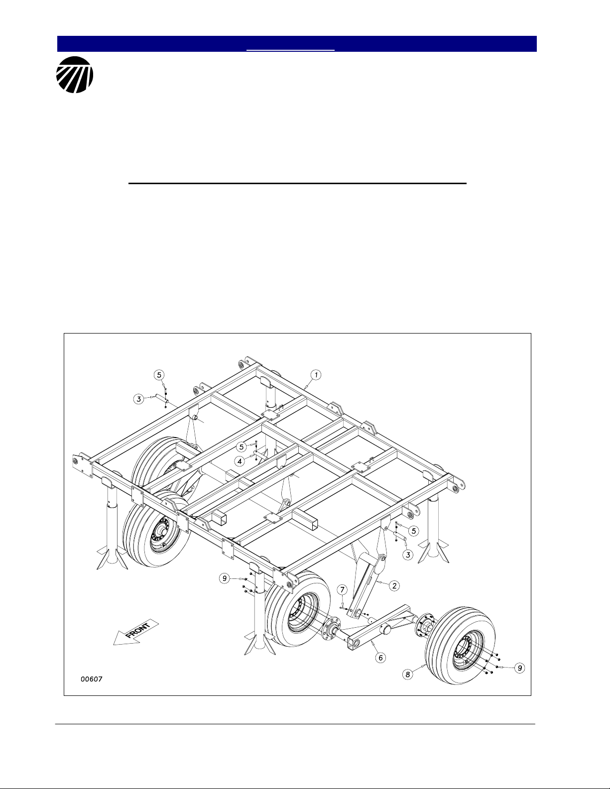
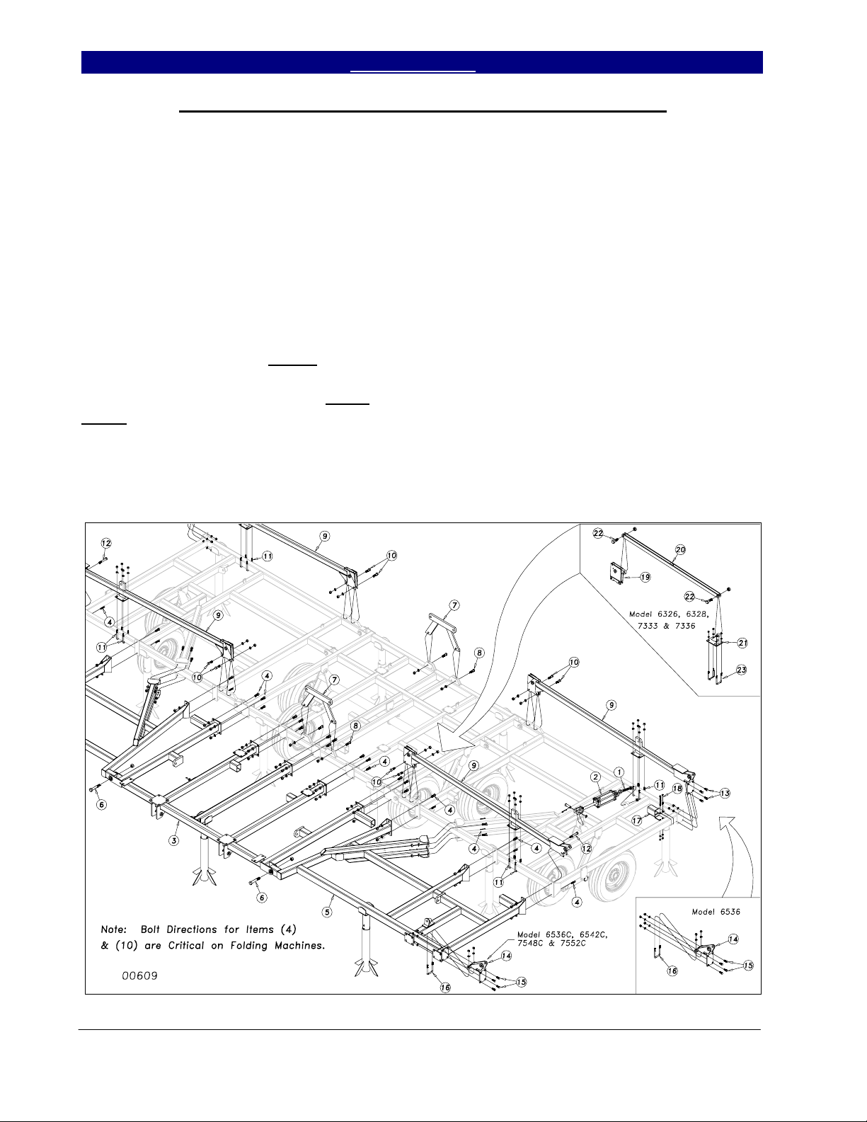
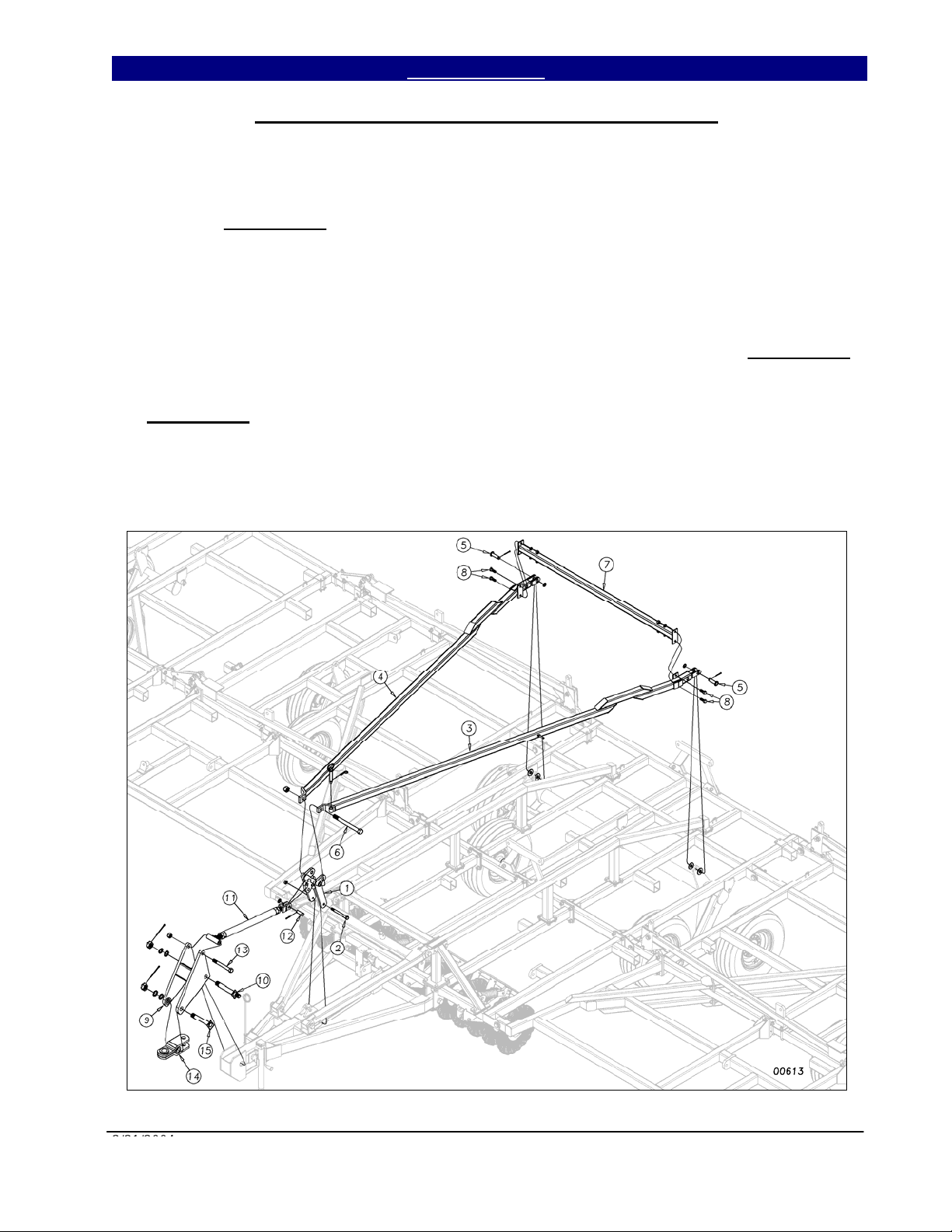
Center Frame, Torque Tube & Walking Beam Assembly
After uncrating the machine, place the
center frame (1) Figure 1, in the center of your
work area on stands. Pin the torque tube (2) to
the center frame with the 1¼ x 6 pins (3) and
1¼ x 7 pin (4) in center. Secure them with 3/8 x
2¼ GR 8 hex bolts (5) & lock nuts.
Slide the pivot spindle of the walking
beam assembly (6) into the sleeve at the end of
the torque tube wheel arm. It is a good idea to
put some form of anti-seize on the spindle
before you insert it. Line up the hole in the
spindle with the hole in the sleeve and secure
with 5/16 x 4 hex bolt (7) with lock washer and
hex nut.
When both walking beams have been
installed, bolt on the center transport tires (8),
using 1/2” or 5/8” lug nuts (9). See Section 3
Replacement Parts for proper transport parts
and sizes for your machine model.
Figure 1
Series VII 6326-7552 Discovator 550-221M 3/31/2004
11/22/2004
14
Great Plains Mfg., Inc. Table of Contents ► Section 1: Assembly
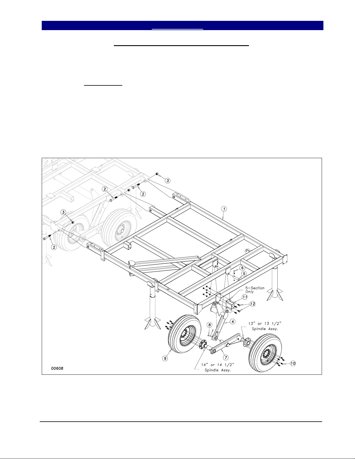
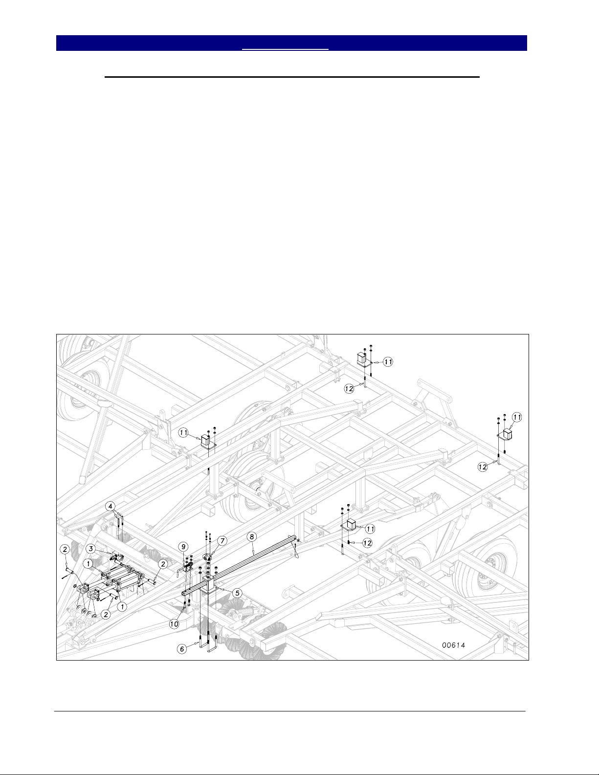
Inside Wing and Wheel Arm Assembly
Bolt the inside wing frames (1) Figure
2, to the center frame with three 1 x 6 hex bolts
(2) with nylon lock nuts (3). Draw the nuts
down tight but do not torque
Once the wings are attached, insert the
wheel arm bracket (4) into the wing frame
hangers and secure it just as you did on the
center with 1¼ x 6 pins (5). Secure the pins
with 3/8 x 2¼ GR 8 hex bolts (6) & lock nuts.
Install the wing walking beam assembly
(7) as shown in Figure 2 with the long 14” or
.
heavy hub 14 ½”, spindle toward the front. Use
anti-seize material on spindle. Secure the pivot
spindle in the sleeve with the 5/16 x 3 clevis
pin (8) and 1/8 x 1 cotter.
Bolt the 9.5L x 15, 8-ply tire (9) in
place with the ½ x 1¼ lug bolts (10), or ½” lug
nuts for heavy hub option. On 5-Section
models, bolt the 5” bolt on stub (11) to the
wing frame using 5/8 x 1½ hex bolts (12),
using lock washers and hex nuts.
Figure 2
3/31/2004 Series VII 6326-7552 Discovator 550-221M
11/22/2004
15
Section 1: Assembly Table of Contents ► Great Plains Mfg., Inc.
Brace Bar, Wing Brace & Rocker/Fold Bracket Assembly
Install the 1 x 7½ or the 1¼ x 9½ eyebolt (1) Figure 3, in the mounting bracket at the
back of the wing with a jam nut on each side of
the bracket. Install the 3¼ x 8 (3 3/4 x 8 for
7548 & 7552) rephasing wing cylinder (2)
between the eyebolt and the lever on the wheel
bracket. Pin the cylinder with 1 x 3 clevis pins,
1” machine washers and 3/16 x 2 cotter pin.
Bolt the center brace bar (3) and wing
brace bar (5) to the front of the center frame
and wing frame with ¾ x 2 hex bolts (4) with
lock washers and hex nuts. Do not tighten
bolts. Use a 1 x 6 hex bolt (6) and nylon lock
nut in the hinge. Draw nut tight but do not
torque. Tighten all other bolts evenly to
prevent bind at hinge.
Bolt the front (and rear on larger
models) center fold bracket(s) (7) to the center
frame with two ¾ x 2½ hex bolts (8) with lock
washer and hex nuts.
rocker/fold bracket(s) (9) to the wing using two
¾ x 2½ hex bolts (10) with lock washers and
hex nuts, along with two 5/8 x 3 x 5½ u-bolts
(11) with lock washer and hex nuts. The front
bracket uses a ¾ x 5 bolt (12) to attach the
outer end. The rear bracket uses four 5/8 x 1½
bolts (13) with lock washers and hex nuts to
attach the outer end. Bolt the inside hinge (14)
to the wing brace using 5/8 x 1½ bolts (15) and
one 5/8 x 3 x 5½ u-bolt (16) with lock washers
and hex nuts. On model 6542, bolt the 4” KFlex stub (17) to the wing frame using 1/2 x 5½
bolts (18) with lock washers and hex nuts.
(19), connecting link (20) and connecting link
bracket (21). Assemble with 1 x 3 hex bolts
(22) with 1” lock nuts, ½ x 3 x 5 u-bolts (23)
with lock washers and hex nuts.
On 5-section models, bolt the
3-Section models have rocker bracket
Figure 3
Series VII 6326-7552 Discovator 550-221M 3/31/2004
2/07/2005
16

Great Plains Mfg., Inc. Table of Contents ► Section 1: Assembly
Outside Wing Assembly
On 5-section models, assemble the
outside wing (1) by attaching the outside hinges
(2) to the wing with 1 x 6 hex bolt (3) and 5/8 x
3 x 5½ u-bolts (4) as shown in Figure 4. Use a
nylon lock nut on the 1 x 6 hex bolt (3) with
lock washers and hex nuts on the u-bolt.
Attach the 180 degree rocker (5), bulge side
out, with the 1 x 3 3/8 usable headed pin (6), 1”
machine washer and 3/16 x 2 cotter pin.
Attach the outside wheel bracket (7) just
as we did the inside ones, using the 1¼ x 6
pins (8) and 3/8 x 2¼ GR 8 hex bolts & lock
nuts. Slide the walking beam assembly (9) into
the wheel bracket sleeve as shown in Figure 4.
Again, it is recommended to use some form of
anti-seize product on the spindle. Secure with
5/16 x 3 clevis pin (10) and 1/8 x 1” cotter pin.
Note that the longer 14” long spindle assembly
(or 14 ½” with heavy hub option) goes to the
front. Bolt on the 9.5L x 15 tire and wheels
(11) with the ½ x 1¼ lug bolts (12) or ½” lug
nuts with the heavy hubs.
Models 6536 & 6542 use one tire and a
14 1/2” Hub & Spindle assembly (13) as shown
in insert.
Figure 4
3/31/2004 Series VII 6326-7552 Discovator 550-221M
11/22/2004
17
Section 1: Assembly Table of Contents ► Great Plains Mfg., Inc.
Connecting Outside Wing and Wing Brace Assembly
On 5-section models, bolt the outside
wing assembly (1) to the inside wing frame
with grade 8, 1 x 6 hex bolts, 1¾ thread (2)
Figure 5, securing with 1” nylon lock nuts.
Bolt the outside wing brace (3) to the
plate on the outside wing with ¾ x 2 hex bolts
(4), with lock washers and hex nuts.
Attach the 3 x 8 (3½ x 8 for 7548 &
7552) rephasing hydraulic cylinder (5) between
the lever on the wheel bracket and the 1 x 7½
eye bolt (6) mounted in the bracket in the back
of the wing. Use 1 x 3½ clevis pins (7) with 1”
machine washer and 3/16 x 2 cotter pins and 1”
jam nuts on the eye-bolt.
On model 6542, attach the 4x4 K-Flex
stub (8) as shown with ½ x 5½ hex bolts (9),
lock washers and hex nuts.
Figure 5
Series VII 6326-7552 Discovator 550-221M 3/31/2004
2/07/2005
18
Great Plains Mfg., Inc. Table of Contents ► Section 1: Assembly
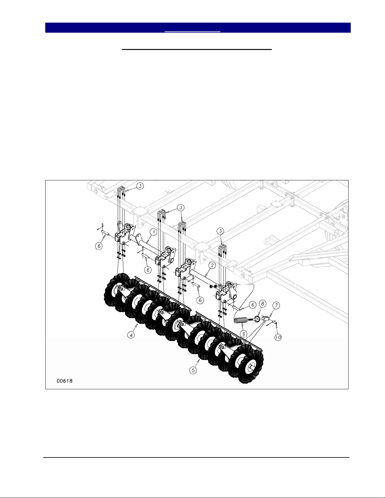
Center Gang & Gang Hanger Assembly
At this time it is best to hang the center
gangs and gang hanger tubes before you install
the hitch and hitch strut assembly, Figure 6.
U-bolt the center right and left gang
hanger tubes (1) & (2) to the center brace bar
with 5/8 x 3 x 5½ u-bolts (3), with lock washers
and hex nuts. Line up the levers on the hanger
tubes with the ratchet jack/cylinder mounts on
the brace bar. Pin the preassembled center
gangs (4) & (5) to the gang hanger tubes (1) &
(2) with the 1 x 5½ pins (6). Secure with 3/8 x
2 clevis pins & 1/8 x 1 cotters. Slide the
spring washer (8) & spring (9) on to the gang
spring bolt (7) as shown and slide it up into the
cast swivel on the gang hanger tubes. Place a
1” flat washer on the spring bolt and thread the
1” hex nut and 1” jam nut onto the spring bolt
(7). Pin the other end to the gang with ¾ x 2½
clevis pins (10), secure with 1/8 x 1½ cotters.
Finally tighten down the nuts on the spring bolt
until the spring has a preload length of 8 3/4”.
Figure 6
3/31/2004 Series VII 6326-7552 Discovator 550-221M
19
Section 1: Assembly Table of Contents ► Great Plains Mfg., Inc.
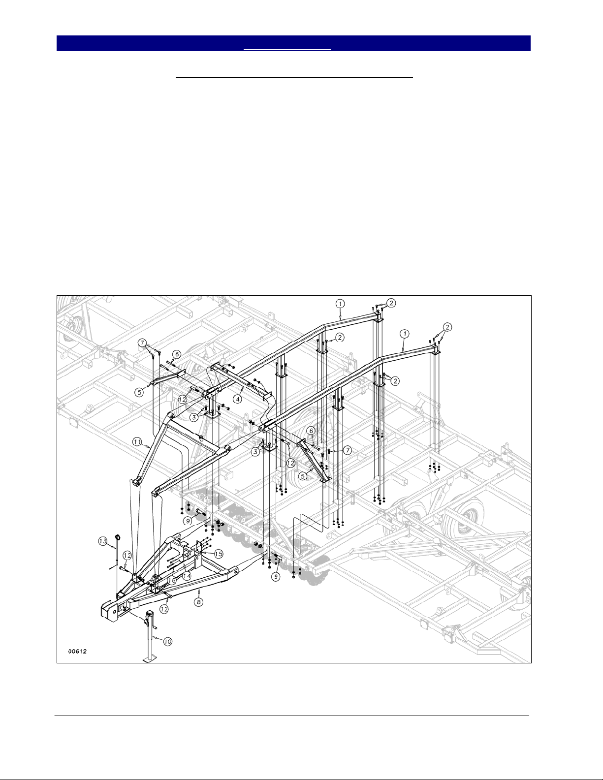
Center Truss, Hitch and Strut Assembly
Bolt the center frame truss (1) Figure 7,
to the top side of the center frame and brace
bar. Use 3/4 x 2 bolts (3) on the front plates
and 5/8 x 1½ bolts (2) on the rear two plates.
Use lock washers and hex nuts on all of these
bolts. On models 6536, 6542, 7333, 7336, 7548
& 7552, bolt the truss cross bar (4) with the
truss legs (5) through the truss frame (1) with
the ¾ x 6 bolt (6), lock washers and hex nuts.
Use two ¾ x 2 hex bolts (7) with lock washers
and hex nuts, at the base of the truss legs.
Slide the back of the hitch (8) between
the plates at the front of the brace bar as shown.
Use two 1¼ x 7 GR 8 bolts (9) and 1¼ lock
washers and hex nuts to secure the hitch.
Mount the tongue jack (10) to the front of the
hitch to support it.
Use 1 x 5½ bolts (12) to attach the hitch
strut (11) between the front of the truss and the
hitch. Use lock washers and hex nuts on these
bolts.
Slide the hose support (13) rod into the
tube at the front of the hitch and secure it with a
1/8 x 1½ cotter pin. Attach the rebound valve
mounting bracket (14) and valve mounting
bracket plate (15) with four ½ x 4½ bolts (16)
using lock washers and hex nuts.
Figure 7
Series VII 6326-7552 Discovator 550-221M 3/31/2004
8/11/2008
20
Great Plains Mfg., Inc. Table of Contents ► Section 1: Assembly
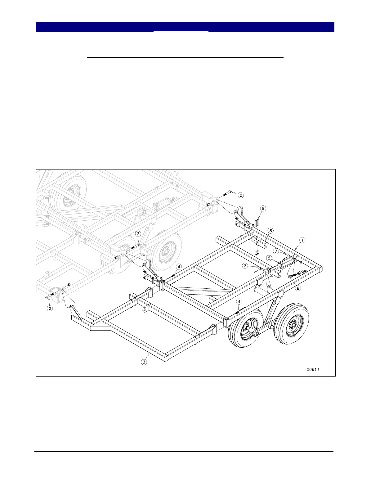
Hitch Tongue, Side Plate and Level Bar Assembly
Slide the H-bracket (1) down over the
hitch pole as shown in Figure 8. Bolt in place
with a ¾ x 8 bolt (2) and ¾” lock nut. Draw
this nut up but do not torque
pivot.
Insert the level bars (3) and (4) through
the previously assembled truss and connect to
the torque tube using two 1 x 3 3/8 usable
clevis pins (5), 1” flat washers, one 1” machine
washer and 3/16 x 2 cotter pins. Install the 1 ¼
x 13½ GR 8 bolt (6) through the level bars and
H-bracket. Draw up snug with a 1¼ top lock
nut (do not torque).
Connect the level bar cross brace (7)
between the level bars and bolt in place with ¾
x 2 hex bolts (8) using hex nuts and lock
washers. Slide the side plate weldment (9) over
the end of the hitch and bolt in place as shown
, as this part must
with the 1½ x 12 safety chain hitch bolt (10).
Secure with 1½ slotted hex nut and ¼ x 3 cotter
pin. Use the 1½ machine washers as needed
for proper fit. Connect the turnbuckle (11)
between the side plate assembly and the Hbracket (1). Use a 1 x 3 3/8 usable clevis pin
(12) with machine washer and 3/16 x 2 cotter
pin at the back end of turnbuckle. Use a 1 x 9
GR 8 bolt (13) with a nylon lock nut at the tee
end of the turnbuckle. Snug, but do not torque
nylon lock nut.
Insert the hitch clevis (14) into the front
of the side plate weldment (9) and bolt in place
with a 1½ x 9 3/8 hitch bolt (15). Secure with
slotted hex nut, machine washers and ¼ x 3
cotter pin, using the 1½ machine washers again
as needed for proper fit.
Figure 8
3/31/2004 Series VII 6326-7552 Discovator 550-221M
11/22/2004
21
Section 1: Assembly Table of Contents ► Great Plains Mfg., Inc.
Center Lift Cylinder, Rest Pads and Hydraulic Valves Assembly
Connect the two 3½ x 8 (4 x 8 for 7548
& 7552) rephasing main lift cylinders (1) to
the center hitch pole as in Figure 9. Connect
the rod ends to the lugs on the H-bracket.
Place a 1” flat washer on each side of the lug
on the H-bracket to keep the hardened
bushings from coming out.
Secure the cylinders with 1 x 3½”
clevis pins (2), 1” machine washers and 3/16 x
2 cotter pins. Mount the rebound valve (3) as
shown with the V1 port to the front and top
using two 5/16 x 4 hex bolts (4) with lock
washers and hex nuts.
Install the depth stop mounting bracket
(5) to the center brace bar using two 5/8 x 3 x
5½, (Disc) or 5/8 x 4 x 5 ½ (Coulter) u-bolts
(6), lock washers and hex nuts. Bolt the depth
stop valve (7) on top of the bracket using the
5/16 x 2 hex bolts with lock washers. Insert
the depth stop tube (8) into the mounting
bracket (5) and attach to the level bar with ½
flat washer and 1/8 x 1 cotter pin. Bolt the
depth stop assembly (9) onto depth stop tube
(8) with two ½ x 2½ hex bolts (10) using ½”
lock washers and hex nuts.
U-bolt the 3 1/2” cylinder rest pads
(11) on the center bar as shown, using a ½ x 3
x 5 u-bolts (12) with lock washers and hex
nuts (see shank layout drawing for exact
placement). On double fold models, u-bolt the
3½” cylinder rest pads (11) on the back bar
using a ½ x 3 x 5 u-bolts (12) with lock
washers and hex nuts.
Figure 9
Series VII 6326-7552 Discovator 550-221M 3/31/2004
2/07/2005
22
Great Plains Mfg., Inc. Table of Contents ► Section 1: Assembly
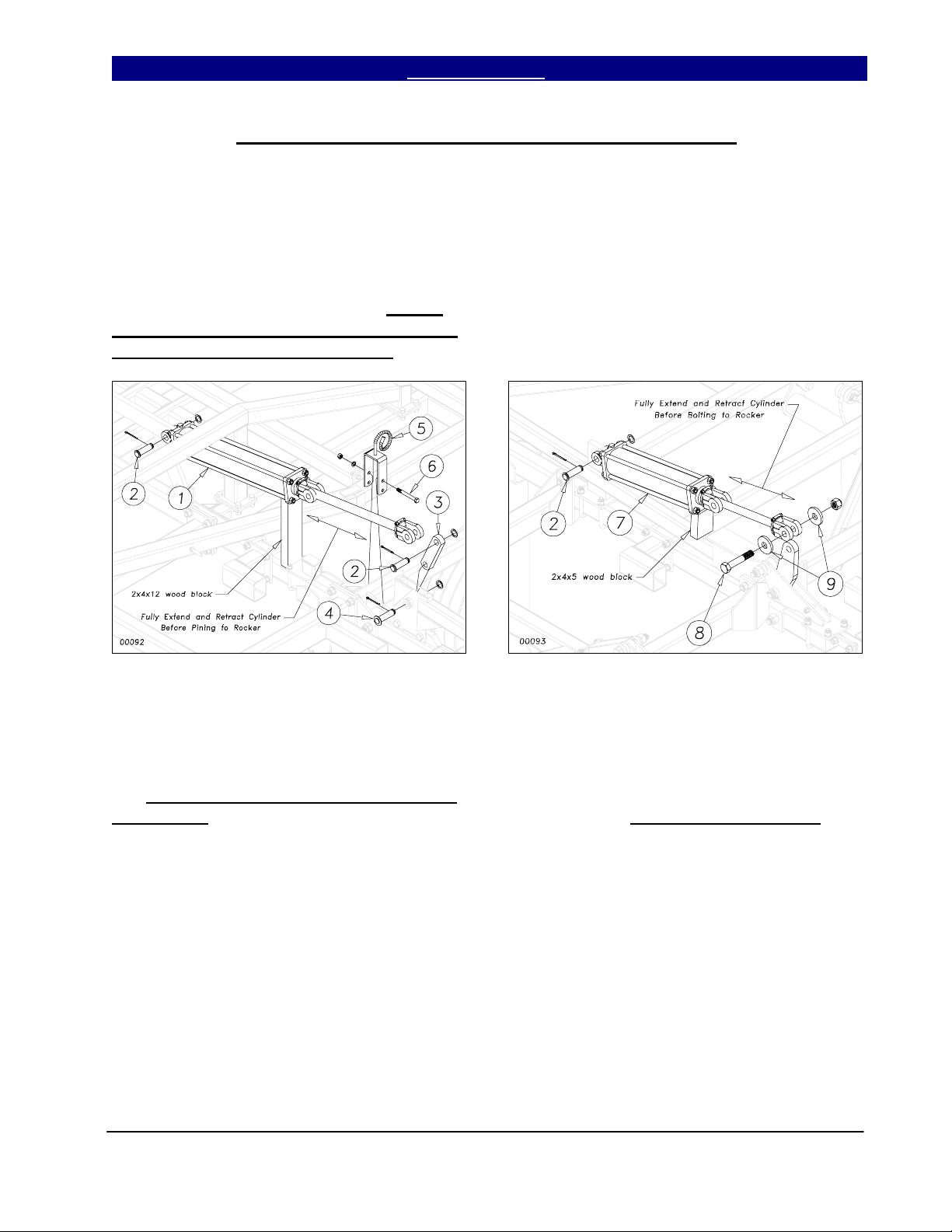
Fold Cylinders, Rocker Arm and 3” Rollers Assembly
Connect the center fold 4 x 24
cylinders (1) to the center fold bracket as
shown in Figure 10. Use the 1” x 3½ clevis
pin (2) with 1” machine washer and 3/16 x 2
cotter pin. Attach the rocker (3) to rocker
bracket with 1 x 3 Headed Pin (4) using 1”
machine washer and 3/16 x 2 cotter. Do Not
Connect Rod End Of Cylinders To Rockers
Before They Are Charged With Oil.
the cylinders, as shown, so they clear the
rockers in the extended position. You are now
ready to connect the hydraulic hoses to the
cylinders and charge the fold system (see
hydraulic layout).
Place a support block of wood under
Figure 10
On 5-section models, connect the base
of the 4 x 16 DB fold cylinders (7) to the
Rocker/Fold bracket with 1 x 3½ clevis pin
(2), 1” machine washer and cotter (see Figure
10). Do Not Connect Rod End Of Cylinders
To Rockers. Bolt the hose holders (5) to the
center frame with a ½ x 4½ hex bolt (6), using
a lock washer and hex nut.
Figure 11
Once the fold cylinders are fully
charged and free of air, connect them to the
rockers. Use a 1 x 5½ bolt (8) to bolt two 3”
rollers (9), one on each side, to the 180 degree
rocker as shown in Figure 11. Secure with 1”
nylon lock nut. Rollers must turn freely!
3/31/2004 Series VII 6326-7552 Discovator 550-221M
23
Section 1: Assembly Table of Contents ► Great Plains Mfg., Inc.
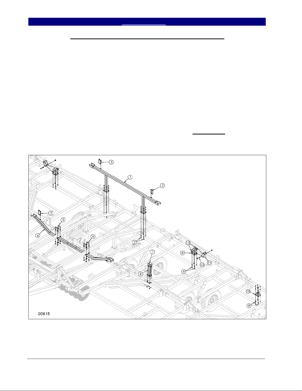
Center Wing Stop and Outside Wing Stop Assembly
U-bolt the center wing stop (1) to the
second bar from the rear on the center frame as
shown in Figure 12. Use 1/2 x 3 x 5 u-bolts
(2) with lock washers and hex nuts. Center the
wing stop from side to side. Insert the ½ x 4½
transport lock quick pins (3) in the holders on
the wing stop.
On models 7548 & 7552, u-bolt the
front center wing stop (4) to the bottom of the
center frame truss using 5/8 x 3 x 4½ u-bolts
(5), lock washers and hex nuts. Bolt the wing
rest (6) to the rocker/fold bracket with 4-hole
clamp plate and ½ x 4½ hex bolts (7), lock
washers and hex nuts (See layout for
placement).
lock mount (8) on the inside wing with ½ x 3 x
5 u-bolts (9). U-bolt the wing lock “T”
bracket (10) on the outside wing with the same
½ x 3 x 5 u-bolt (9). Refer to the shank layout
for your particular model for the exact location
of the wing lock mount and lock “T” bracket.
Use lock washers and hex nuts on these ubolts. Bolt the wing latch (11) to the wing lock
mount (8) with a ¾ x 4½ bolt (12). Slide a ¾
flat washer (13) between the latch and the
mount on each side to take out the slop. Use a
¾” lock nut but do not torque
latch must move freely.
On 5-section models, u-bolt the wing
down. The
Figure 12
Series VII 6326-7552 Discovator 550-221M 3/31/2004
24
Great Plains Mfg., Inc. Table of Contents ► Section 1: Assembly
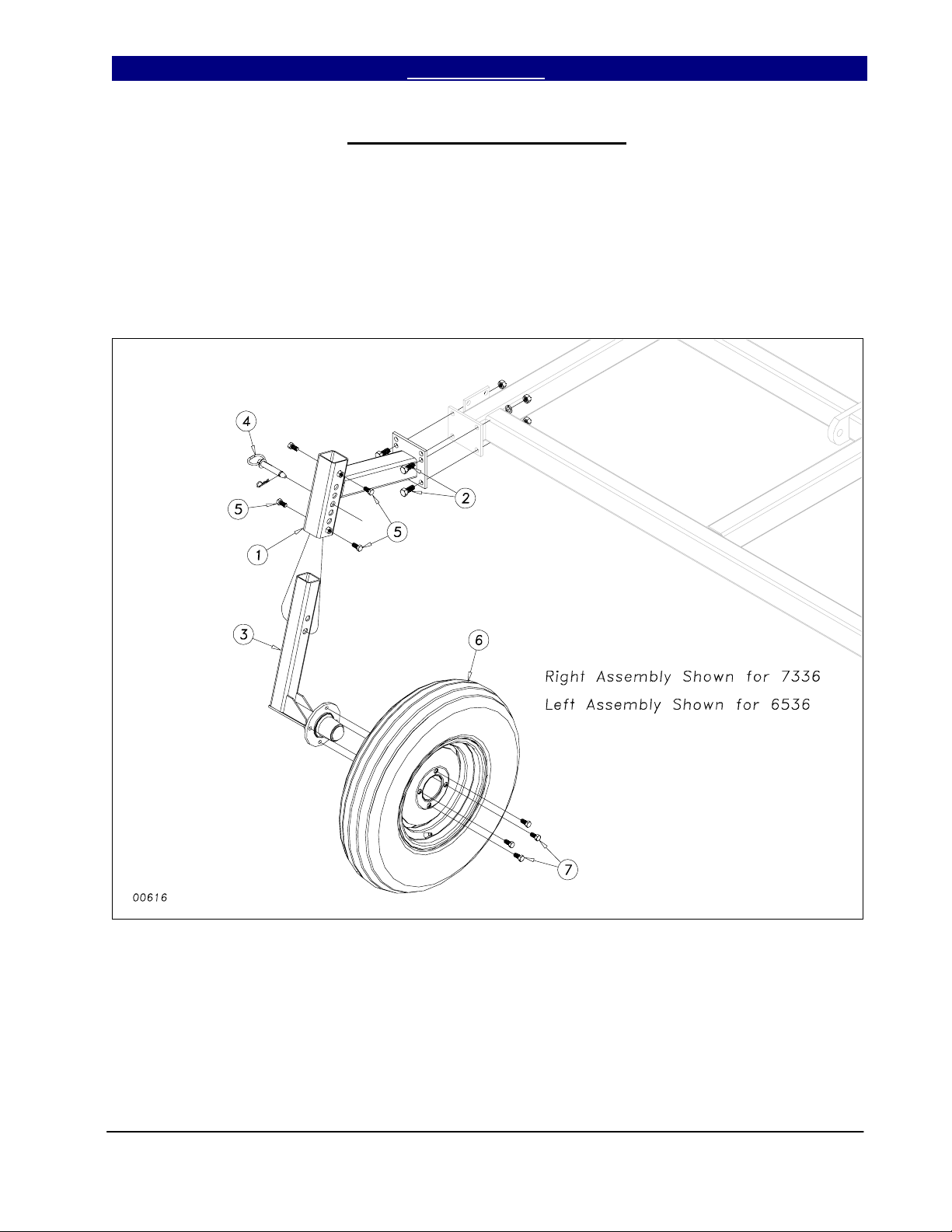
Front Gauge Wheel Assembly
On model 6536 and 7336, bolt the
gauge wheel bracket (1) to the front plate of
wing brace as shown in Figure 13 using the 5/8
x 1½ hex bolts (2), lock washers and hex nuts.
Slide the gauge wheel arm/hub assembly (3)
up into the gauge wheel bracket (1) and pin
with the ¾ x 5¼ usable pin (4). Use four ½ x
1 hex bolts (5) to secure the arm and make it
rigid. Bolt on the 4-bolt rim and tire (6) with
four ½ x 1 lug bolts (7). For directions on the
proper setting for the gauge wheel during
operation, refer to section 5.
Figure 13
3/31/2004 Series VII 6326-7552 Discovator 550-221M
2/07/2005
25
Section 1: Assembly Table of Contents ► Great Plains Mfg., Inc.
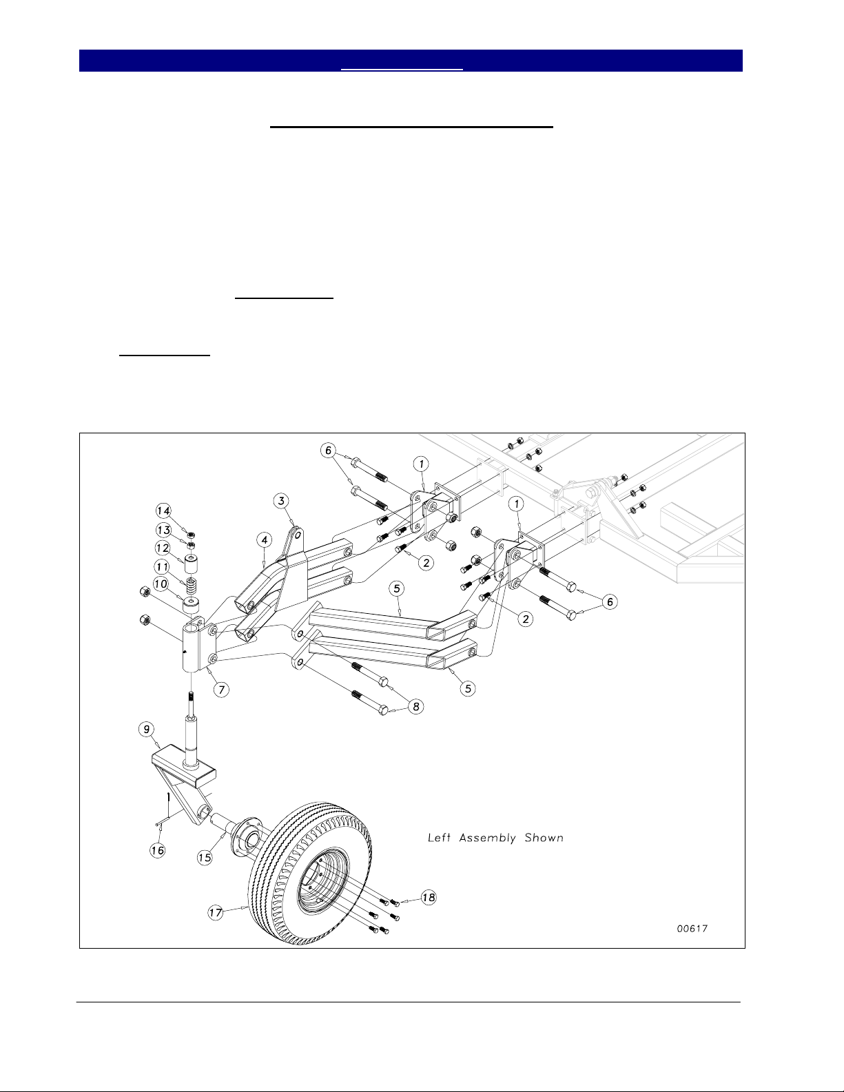
Hydraulic Gauge Wheel Assembly
On model 6542, 7548 & 7552, bolt the
gauge wheel arm mount clevis (1) to the front
bar of wing brace as shown in Figure 14 using
the 5/8 x 1½ hex bolts (2), lock washers and
hex nuts. Insert the linkage arms (3) and (4)
and hydraulic gauge wheel arms (5) into the
arm clevis (1). Assemble with 1 x 6 hex bolt
(6) and nylon lock nut. Do not torque down.
Bolt the pivot bracket (7) to the arms as shown
with 1 x 7 hex bolt (8) and nylon lock nut,
again do not torque. Insert the appropriate left
or right gauge wheel arm (9) into the pivot
bracket (7) and install the friction cap (10),
spring (11), spring cover (12), ¾” hex nut (13)
and ¾” jam nut (14) to secure the assembly.
Insert the hub and spindle assembly (15) into
the gauge wheel arm (9), using anti-seize
material on the spindle. Secure with 5/16 x 3
clevis pin (16) and 1/8 x 1 cotter. Bolt on the
rim and tire assembly (17) with six ½ x 1¼
lug bolts (18). Install the gauge wheel
hydraulic cylinders (or ratchet jacks) as per
hydraulic layout for your machine, section 2.
Use 1 x 8½ eye-bolts with 1” jam nuts at the
base of the cylinders. For directions on the
proper setting for the hydraulic gauge wheel
during operation, refer to section 5.
Figure 14
Series VII 6326-7552 Discovator 550-221M 3/31/2004
11/22/2004
26

Great Plains Mfg., Inc. Table of Contents ► Section 1: Assembly
Completing Setup
Install the plastic end caps into all the
open ends of all the 4x3 frame tubes.
You should now be ready to add
shanks and the remaining gangs to the
machine. If the machine has a finishing
attachment you would install it last. See the
machine layout Section 4 for proper shank and
gang locations for your unit. Section 3 in the
manual shows the individual shank assemblies
and parts for both the K-flex and magnum
shanks along with gang parts and identification
drawings.
Once the shanks and gangs are
installed and all of the hydraulic procedures
have been completed, you may fold the
machine to check for clearance and proper
shank placement. Slowly fold the machine
while watching that hoses do not become
pinched or kinked and watch that shanks clear
all obstructions.
begin to unfold slowly. Be Sure No One Is
Under The Wings When You Unfold The
Machine. Once the machine is unfolded, add
the safety decals and the product decals. Refer
to the Important Safety Information (page 7)
for the proper placement of safety decals.
safety lights in accordance with local and state
laws. See parts manual (Section 6: Safety) for
assembly drawings and parts list.
complete and you are ready to add any
finishing attachment, rear hitches, etc… to the
machine. Be sure to consult the operating
instructions, Section 5, for the first time field
adjustments before going to the field for the
first time.
Once the machine is folded completely,
Install the safety chain, SMV sign &
At this point, set up of the machine is
3/31/2004 Series VII 6326-7552 Discovator 550-221M
2/07/2005
27

Section 2: Hydraulics Table of Contents ► Great Plains Mfg., Inc.
Hydraulic Layout: 6326, 6328, 7333 & 7336
00653
Series VII 6326-7552 Discovator 550-221M 12/23/2004
2/07/2005
28

Great Plains Mfg., Inc. Table of Contents ► Section 2: Hydraulics
Hydraulic Layout: 6326, 6328, 7333 & 7336
Ref. Kent No. GP Part No. Part Description Comments
1. 810-479C CYL REP 3.50x8x1.25 Tie 3000# GP Seal Kit# 810-174C
2. 810-478C CYL REP 3.25x8x1.25 Tie 3000# GP Seal Kit# 810-173C
3. 810-487C CYL 4X24X1.5 Tie 34.63 CL 3000# GP Seal Kit# 810-060C
4. 810-622C Rebound Valve
FC1342 REP BY 810-622C
5. FC0218 810-511C Depth Control Valve Cartridge #3C7272
6. 811-088C Adaptor, AD 3/4 MORB 3/4 MJIC
7. 811-063C Elbow, EL 3/4MJIC 3/4MORB
8. 196-430D Orifice Restrictor, ORPL 1/16 3/4MORB
811- 845C Replaced by 196-430D
9. 811-078C Tee, TE 3/4MJIC
10. HF0034 811-857C 3/4 O-Ring Plug
11. 811-974C HH3/8R2 135 3/4MORB 3/4FJIC Models 6326 & 6328
811-893C HH3/8R2 147 3/4MORB 3/4FJIC Models 7333 & 7336
12. 811-977C HH3/8R 2 053 3/4FJIC
13. 811-949C HH3/8R 2 015 3/4FJIC
14. 811-889C HH3/8R 2 303 3/4FJIC Models 6326
811-981C HH3/8R2 317 3/4FJIC Models 6328
811-990C HH3/8R2 357 3/4FJIC Models 7333
811-994C HH3/8R2 359 3/4FJIC Models 7336
15. 811-976C HH3/8R 2 139 3/4FJIC Models 6326
811-975C HH3/8R2 153 3/4FJIC Models 6328
811-991C HH3/8R2 187 3/4FJIC Models 7333
811-884C HH3/8R2 209 3/4FJIC Models 7336
16. 811-975C HH3/8R 2 153 3/4FJIC Models 6326 & 6328 & 7336
811-909C HH3/8R2 163 3/4FJIC Models 7333
17. 811-965C HH3/8R2 207 3/4MORB 3/4FJIC Models 6326 & 6328
841-042C HH3/8R2 249 3/4MORB 3/4FJIC Models 7333
811-992C HH3/8R2 235 3/4MORB 3/4FJIC Models 7336
18. 811-943C HH3/8R 2 033 3/4FJIC
19. 811-952C HH3/8R 2 057 3/4FJIC
20. 811-826C Hydra Grip Handle, Black Extend
21. 811-913C Hydra Grip Handle, Black Retract
22. 811-919C Adaptor, AD 3/ 4 MORB 3/4 FORB (HG)
23. 548-001S HG Pair Black MORB-FORB Includes items 20, 21 & 22
24. 811-394C Coupler, CP 3/4 FORB MALE QD Poppet Type
25. 811-915C H ydra Grip Handle - Green Extend
26. 811-916C Hydra Grip Handle - Green Retract
27. 548-003S HG Pair Green MORB-FORB Includes items 25, 26 & 22
28. 575-268D Hose Wrap, Large Size, Short 8”
550-123D Hose Wrap, Small Size, Short 8”
Legend: = 1st revision; = 2nd revision, = 3rd revision; use up existing stock; ⊗ not interchangeable; ⊗Revision 2 is not interchangeable with 1
12/23/2004 Series VII 6326-7552 Discovator 550-221M
8/11/2008
29

Section 2: Hydraulics Table of Contents ► Great Plains Mfg., Inc.
Hydraulic Layout, 6536
00654
Series VII 6326-7552 Discovator 550-221M 12/23/2004
2/07/2005
30

Great Plains Mfg., Inc. Table of Contents ► Section 2: Hydraulics
Hydraulic Layout, 6536
Ref Kent No. GP Part No. Part Description Comments
29. 810-479C CYL REP 3.50x8x1.25 Tie 3000# GP Seal Kit# 810-174C
30. 810-478C CYL REP 3.25x8x1.25 Tie 3000# GP Seal Kit# 810-173C
31. 810-477C CYL REP 3x8x1.25 Tie 3000# GP Seal Kit# 810-211C
32. 810-487C CYL 4x24x1.5 Tie 34.63 CL 3000# GP Seal Kit# 810-060C
33. 810-486C CYL 4x16x1.25 Tie 26.63 CL 3000# GP Seal Kit# 810-013C
34. 810-622C Rebound Valve
FC1342 REP BY 810-622C
35. FC0218 810-511C Depth Control Valve Cartridge #3C7272
36. 811-088C Adaptor, AD 3/4 MORB 3/4 MJIC
37. 811-063C Elbow, EL 3/4MJIC 3/4MORB
38. 196-430D Orifice Restrictor, ORPL 1/16 3/4MORB
811- 845C Replaced by 196-430D
39. 811-078C Tee, TE 3/4MJIC
40. 811-077C Tee, TE 3/4MORB 3/4MJIC 3/4MJIC
41. HF0034 811-857C 3/4 O-Ring Plug
42. 811-974C HH3/8R2 135 3/4MORB 3/4FJIC
43. 811-977C HH3/8R 2 053 3/4FJIC
44. 811-949C HH3/8R 2 015 3/4FJIC
45. 811-889C HH3/8R 2 303 3/4FJIC
46. 811-983C HH3/8R 2 073 3/4FJIC
47. 811-884C HH3/8R 2 209 3/4FJIC
48. 811-975C HH3/8R 2 153 3/4FJIC
49. 811-965C HH3/8R2 207 3/4MORB 3/4FJIC
50. 811-943C HH3/8R 2 033 3/4FJIC
51. 811-905C HH3/8R 2 121 3/4FJIC
52. 811-127C HH3/8R 2 111 3/4FJIC
53. 811-952C HH3/8R 2 057 3/4FJIC
54. 811-826C Hydra Grip Handle, Black Extend
55. 811-913C Hydra Grip Handle, Black Retract
56. 811-919C Adaptor, AD 3/ 4 MORB 3/4 FORB (HG)
57. 548-001S HG Pair Black MORB-FORB Includes items 26,27 & 28
58. 811-394C Coupler, CP 3/4 FORB MALE QD Poppet Type
59. 811-915C H ydra Grip Handle - Green Extend
60. 811-916C Hydra Grip Handle - Green Retract
61. 548-003S HG Pair Green MORB-FORB Includes items 29, 30 & 28
62. FC1790 575-268D Hose Wrap, Large size, Short 8”
FC1792 550-123D Hose Wrap, Small size, Short 8”
12/23/2004 Series VII 6326-7552 Discovator 550-221M
8/11/2008
31

Section 2: Hydraulics Table of Contents ► Great Plains Mfg., Inc.
Hydraulic Layout: 6542, 7548 & 7552
00655
Series VII 6326-7552 Discovator 550-221M 12/23/2004
8/11/2008
32

Great Plains Mfg., Inc. Table of Contents ► Section 2: Hydraulics
Hydraulic Layout: 6542, 7548 & 7552
Ref Kent No. GP Part No. Part Description Comments
1. 810-479C CYL REP 3.50x8x1.25 Tie (Model 6542) GP Seal Kit# 810-174C
810-138C CYL REP 4x8x1.38 Tie (Model 7548 & 7552) GP Seal Kit# 810-151C
2. 810-478C CYL REP 3.25x8x1.25 Tie (Model 6542) GP Seal Kit# 810-173C
810-480C CYL REP 3.75x8x1.38 Tie (Model 7548 & 7552) GP Seal Kit# 810-373C
3. 810-477C CYL REP 3x8x1.25 Tie (Model 6542) GP Seal Kit# 810-211C
810-479C CYL REP 3.50x8x1.25 Tie (Model 7548 & 7552) GP Seal Kit# 810-174C
4. 810-476C CYL REP 2.75x8x1.12 Tie (Model 6542) GP Seal Kit# 810-513C
810-478C CYL REP 3.25x8x1.25 Tie (Model 7548 & 7552) GP Seal Kit# 810-173C
5. 810-487C CYL 4x24x1.5 Tie 34.63 CL 3000# GP Seal Kit# 810-060C
6. 810-486C CYL 4x16x1.25 Tie 26.63 CL 3000# GP Seal Kit# 810-013C
7. 810-622C Rebound Valve
FC1342 REP BY 810-622C
8. FC0218 810-511C Depth Control Valve Cartridge #3C7272
9. 811-088C Adaptor, AD 3/4 MORB 3/4 MJIC
10. 811-063C Elbow, EL 3/4MJIC 3/4MORB
11. 196-430D Orifice Restrictor, ORPL 1/16 3/4MORB
811- 845C Replaced by 196-430D
12. 811-078C Tee, TE 3/4MJIC
13. 811-077C Tee, TE 3/4MORB 3/4MJIC 3/4MJIC
14. 811-147C Cross, CR 3/4 MJIC
15. HF0034 811-857C 3/4 O-Ring Plug
16. 811-974C HH3/8R2 135 3/4MORB 3/4FJIC Model 6542
811-893C HH3/8R2 147 3/4MORB 3/4FJIC Model 7548 & 7552
17. 811-977C HH3/8R 2 053 3/4FJIC
18. 811-949C HH3/8R 2 015 3/4FJIC
19. 811-981C HH3/8R 2 317 3/4FJIC Model 6542
811-990C HH3/8R2 357 3/4F JIC Model 7548 & 7552
20. 811-127C HH3/8R 2 111 3/4FJIC Model 6542
811-671C HH3/8R2 099 3/4F JIC Model 7548
811-987C HH3/8R2 127 3/4F JIC Model 7552
21. 811-986C HH3/8R 2 241 3/4FJIC Model 6542, 7548
811-946C HH3/8R2 271 3/4FJIC Model 7552
22. 811-970C HH3/8R 2 219 3/4FJIC Model 6542
811-961C HH3/8R2 261 3/4FJIC Model 7548 & 7552
23. 811-978C HH3/8R 2 093 3/4FJIC
24. 811-965C HH3/8R2 207 3/4MORB 3/4FJIC Model 6542
811-995C HH3/8R2 237 3/4MORB 3/4FJIC Model 7548 & 7552
25. 811-943C HH3/8R 2 033 3/4FJIC
26. 811-906C HH3/8R 2 135 3/4FJIC Model 6542
811-982C HH3/8R2 149 3/4F JIC Model 7548 & 7552
27. 811-851C HH3/8R 2 126 3/4FJIC Model 6542
811-126C HH3/8R2 140 3/4F JIC Model 7548 & 7552
28. 811-952C HH3/8R 2 057 3/4FJIC
29. 811-988C HH3/8R 2 089 3/4FJIC
30. 811-826C Hydra Grip Handle, Black Extend
31. 811-913C Hydra Grip Handle, Black Retract
32. 811-919C Adaptor, AD 3/ 4 MORB 3/4 FORB (HG)
33. 548-001S HG Pair Black MORB-FORB Includes items 29,30 & 31
34. 811-394C Coupler, CP 3/4 FORB MALE QD Poppet Type
35.
811-915C Hydra Grip Handle - Green Extend
36. 811-916C Hydra Grip Handle - Green Retract
37. 548-003S HG Pair Green MORB-FORB Includes items 34, 35 & 31
38. FC1790 575-268D Hose Wrap, Large size, Short 8”
FC1792 550-123D Hose Wrap, Small size, Short 8”
12/23/2004 Series VII 6326-7552 Discovator 550-221M
8/11/2008
33

Section 2: Hydraulics Table of Contents ► Great Plains Mfg., Inc.
Hydraulic Gang Layout
00656
Series VII 6326-7552 Discovator 550-221M 12/23/2004
34

Great Plains Mfg., Inc. Table of Contents ► Section 2: Hydraulics
Hydraulic Gang Layout
Ref. Kent No. GP Part No. Part Description Comments
1. 810-479C CYL REP 3.50x8x1.25 rod GP Seal Kit # 810-174C
2. 810-478C CYL REP 3.25x8x1.25 rod GP Seal Kit # 810-173C
3. 810-477C CYL REP 3x8x1.25 rod GP Seal Kit# 810-211C
4. 811-063C Elbow, EL 3/4MJIC 3/4MORB
5. 811-078C Tee, TE 3/4MJIC
6. 811-121C Tee, TE 1/2 MNPT 3/4MJIC 3/4MJIC
7. HF0028 811-853C Restrictor, ORAD 1/8 1WAY 1/2MNPT 1/2FNPT
8. 811-290C Adaptor, AD 3/4MJIC 1/2FNPT
9. 811-979C HH3/8R2 177 3/4MORB 3/4F JIC Model 6326, 6328, 6536, 654 2
811-965C HH3/8R2 207 3/4FJIC Model 7333, 7336, 7548, 7552
10. 811-980C HH3/8R 2 047 3/4FJIC Model 6326, 6328, 6536, 6542
811-993C HH3/8R2 075 3/4FJIC Model 7333, 7336, 7548, 7552
11. 811-978C HH3/8R 2 093 3/4FJIC Model 6326 & 6536
811-687C HH3/8R2 108 3/4FJIC Model 6328 & 6542
811-897C HH3/8R2 123 3/4FJIC Model 7333, 7336, 7548, 7552
12. 811-985C HH3/8R 2 078 3/4FJIC Model 6536 & 6542
811-997C HH3/8R2 084 3/4FJIC Model 7548 & 7552
13. 811-906C HH3/8R 2 135 3/4FJIC Model 6326
811-982C HH3/8R2 149 3/4FJIC Model 6328
811-984C HH3/8R2 203 3/4FJIC Model 6536
811-989C HH3/8R2 213 3/4FJIC Model 6542
811-935C HH3/8R2 177 3/4FJIC Model 7333 & 7336
811-996C HH3/8R2 243 3/4FJIC Model 7548 & 7552
14. 811-914C Hydra Grip Handle, Red Extend
15. 811-827C Hydra Grip Handle, Red Retract
16. 811-919C Adaptor, AD 3/ 4 MORB 3/4 FORB (HG)
17. 548-002S HG Pair Red MORB-FORB Includes items 14, 15 & 16
18. 811-394C Coupler, CP 3/4 FORB MALE QD Poppet Type
19. FC1790 575-268D Hose Wrap, Large Size, Short 8”
FC1789 550-346D Hose Wrap, Large Size, Long 15”
12/23/2004 Series VII 6326-7552 Discovator 550-221M
35

Section 3: Replacement Parts Table of Contents ► Great Plains Mfg., Inc.
Magnum Shank Assembly
00347
Series VII 6326-7552 Discovator 550-221M 1/19/2006
36

Great Plains Mfg., Inc. Table of Contents ► Section 3: Replacement Parts
Regular Magnum Shank Assembly (S/N 1172DD-)
Ref. Kent No. GP Part No. Part Description Comments
1. FC1200 820-297C Shank, 9/16 x 1 3/4 x 30 Min Draft (shown)
FC0032 820-293C Shank, 9/16 x 1 3/4 x 30 Flat
2. FC0001 552-014D Top Spring Plug
3. FC1109 Spring, Shank
4. FC0317 Bottom Spring Plug
5. FC2198 552-050V Spring/Plug Sub Assembly Includes items 2 thru 4
6. FC0331 552-043H Shank Cradle
7. FC1471 552-006D Shank Mount Upright, 4” Tube
8. FC0333 1 x 3/4 x 3 Hardened Bushing
9. UB0032 806-158C U-Bolt, 5/8 x 4 1/32 x 4 3/4
10. 3110 803-024C Lock Nut, 5/8
11. FC0320 802-507C Hex Bolt, 1/2 x 1 1/2, Special
12. FC0319 802-485C Carriage Bolt, 3/4 x 4 1/8 Special
13. 3612J 803-126C Nylon Jam Nut, 3/4
14. FC1169 802-535C Hex Bolt, 1/2 x 3 Gr. 5, Special
15. 3108 803-019C Lock Nut, 1/2
16. 111032 802-055C Hex Bolt, 5/8 x 2
17. 3610 803-148C Nylon Lock Nut, 5/8
18. 820-294C Sweep, 1/4 x 7"
820-292C Sweep, 1/4 x 7" Hard Faced
820-291C Sweep, 1/4 x 7" Ultra Wing
FC1875 Sweep, 1/4 x 9"
FC1879 Sweep, 1/4 x 9" Hard Faced
FC2042 Sweep, 1/4 x 9" Ultra Wing
FC1876 Sweep, 1/4 x 10"
FC1880 Sweep, 1/4 x 10", Hard Faced
FC2043 Sweep, 1/4 x 10" Ultra Wing
FC1877 Sweep, 1/4 x 11"
FC1881 Sweep, 1/4 x 11", Hard Faced
FC2044 Sweep, 1/4 x 11" Ultra Wing
19. 802-090C Plowbolt, 7/16 x 1 3/4, GR 5
20. 4007 804-204C Flat Washer, 7/16
21. 3607 803-245C Nylon Lock Nut, 7/16
22. FC0556 575-860V Sweep 7", w/Bolts Includes items 18 thru 21
575-862V Sweep 7", w/Bolts, Hard Faced Includes items 18 thru 21
575-861V Sweep 7", w/Bolts, Ultra Wing Includes items 18 thru 21
FC0019 570-219V Sweep 9", w/Bolts Includes items 18 thru 21
FC0559 575-809V Sweep 9", w/Bolts, Hard Faced Includes items 18 thru 21
FC1771 575-810V Sweep 9", w/Bolts, Ultra Wing Includes items 18 thru 21
FC0557 575-807V Sweep 10", w/Bolts Includes items 18 thru 21
FC0560 575-767V Sweep 10", w/Bolts, Hard Faced Includes items 18 thru 21
FC1772 575-811V Sweep 10", w/Bolts, Ultra Wing Includes items 18 thru 21
FC0558 575-808V Sweep 11", w/Bolts Includes items 18 thru 21
FC0561 575-804V Sweep 11", w/Bolts, Hard Faced Includes items 18 thru 21
FC1773 575-812V Sweep 11", w/Bolts, Ultra Wing Includes items 18 thru 21
Heavy-Duty Magnum Shank Assembly (S/N 1173DD+)
Ref. Kent No. GP Part No. Part Description Comments
1. FC1576 820-296C Shank, 5/8 x 1 3/4 x 30 Min Draft, Heavy
820-295C Shank, 5/8 x 1 3/4 x 30 Flat
820-351C Shank, 5/8 x 1 3/4 x 30 MD Offset 2
2. FC1970 552-030D 7/16x1.5 ID Top Spring Plug
3. 807-149C Spring Ext 2.42OD .438W 9.69 Lo ng
4. FC1971 812-143C 7/16 x 1.5 ID Bottom Spring Plug
5. 552-057V Heavy Spring/Plug Sub Assembl y Includes items 2 thru 4
All other items same as above.
1/19/2006 Series VII 6326-7552 Discovator 550-221M
37

Section 3: Replacement Parts Table of Contents ► Great Plains Mfg., Inc.
K-Flex Shank Assembly
00029
Series VII 6326-7552 Discovator 550-221M 1/19/2006
38

Great Plains Mfg., Inc. Table of Contents ► Section 3: Replacement Parts
Regular K-Flex Shank Assembly
Ref. Kent No. GP Part No. Part Description Comments
1. FL1475 K-Flex Shank Mount, Regular, 3 x 4 Tube
2. FL1544 552-002D K-Flex Clamp, Regular, 3 x 4 Mount
3. FC1200 820-297C Shank, 9/16 x 1 3/4 x 30 Min Draft (shown)
FC0032 820-293C Shank, 9/16 x 1 3/4 x 30 Flat
820-354C Shank, 9/16 x 1 3/4 x 30 MD Offset 2
4. FC1508 552-001D K-Flex Clip, 4
5. 110880 802-045C Hex Bolt, 1/2 x 5
6. 4108 804-015C Lock Washer, 1/2
7. 3008 803-020C Hex Nut, 1/2
8. FC0320 802-091C Hex Bolt, 1/2 x 1 1/2
9. 111032 802-055C Hex Bolt, 5/8 x 2
10. 3610 803-148C Nylon Lock Nut, 5/8
11. 820-294C Sweep, 1/4 x 7"
820-292C Sweep, 1/4 x 7" Hard Faced
820-291C Sweep, 1/4 x 7" Ultra Wing
FC1875 Sweep, 1/4 x 9"
FC1879 Sweep, 1/4 x 9" Hard Faced
FC2042 Sweep, 1/4 x 9" Ultra Wing
FC1876 Sweep, 1/4 x 10"
FC1880 Sweep, 1/4 x 10", Hard Faced
FC2043 Sweep, 1/4 x 10" Ultra Wing
FC1877 Sweep, 1/4 x 11"
FC1881 Sweep, 1/4 x 11", Hard Faced
FC2044 Sweep, 1/4 x 11" Ultra Wing
12. 802-090C Plowbolt, 7/16 x 1 3/4, GR 5
13. 4007 804-204C Flat Washer, 7/16
14. 3607 803-245C Nylon Lock Nut, 7/16
15. FC0556 575-860V Sweep 7", w/Bolts Includes items 11 thru 14
575-862V Sweep 7", w/Bolts, Hard Faced Includes items 11 thru 14
575-861V Sweep 7", w/Bolts, Ultra Wing Includes items 11 thru 14
FC0019 570-219V Sweep 9", w/Bolts Includes items 11 thru 14
FC0559 575-809V Sweep 9", w/Bolts, Hard Faced Includes items 11 thru 14
FC1771 575-810V Sweep 9", w/Bolts, Ultra Wing Includes items 11 thru 14
FC0557 575-807V Sweep 10", w/Bolts Includes items 11 thru 14
FC0560 575-767V Sweep 10", w/Bolts, Hard Faced Includes items 11 thru 14
FC1772 575-811V Sweep 10", w/Bolts, Ultra Wing Includes items 11 thru 14
FC0558 575-808V Sweep 11", w/Bolts Includes items 11 thru 14
FC0561 575-804V Sweep 11", w/Bolts, Hard Faced Includes items 11 thru 14
FC1773 575-812V Sweep 11", w/Bolts, Ultra Wing Includes items 11 thru 14
16. FL1104 Trip Limiter Optional
17. 110888 802-046C Hex Bolt, 1/2 x 5 1/2 Optional, required with item 16
Heavy K-Flex Shank Assembly
Ref. Kent No. GP Part No. Part Description Comments
1. FL1666 820-299 C K-F lex Shank Mount, Heavy
2. FL1702 552-003D Mounting Clamp, Heavy, 3 x 4 Tube
3. FC1576 820-296C Shank, 5/8 x 1 3/4 x 30 Min Draft, Heavy
820-295C Shank, 5/8 x 1 3/4 x 30 Flat
820-351C Shank, 5/8 x 1 3/4 x 30 MD Offset 2
All other items same as above.
1/19/2006 Series VII 6326-7552 Discovator 550-221M
39

Section 3: Replacement Parts Table of Contents ► Great Plains Mfg., Inc.
Disc Gang Assembly
00462
Series VII 6326-7552 Discovator 550-221M 1/19/2006
40

Great Plains Mfg., Inc. Table of Contents ► Section 3: Replacement Parts
Disc Gang Assembly
Ref. Kent No. GP Part No. Part Description Comments
4. FC0903R 551-032H Bearing Hanger, RH Disc Gang
FC0903L 551-042H Bearing Hanger, LH Disc Gang
5. FC0905 551-078H Gang Bolt, 6 Blade, 44” Models 6326, 6536 & 7552
FC0906 551-079H Gang Bolt, 7 Blade, 52” 6326, 6328, 6536, 6542, 7333 & 7552
FC0907 551-080H Gang Bolt, 8 Blade, 60” Models 7333, 7336, 7548 & 7552
FC0908 551-033H Gang Bolt, 9 Blade, 68” Models 7333, 7336, 7548 & 7552
FC0909 551-081H Gang Bolt, 10 Blade, 76” Models 6542 & 7548
6. PL0365 551-032D Shallow C-Concavity Convex Washer
7. FC1567 20” Disc Blade, Shallow Concavity
8. FC1568 820-274C 18” Disc Blade, Shall ow Concavity
9. FC1569 820-275C 16” Disc Blade, Shall ow Concavity No usage on these models
10. FC1572 551-039H 4 1/16” Half Spool
11. FC0481 822-208C Bearing Flange 1 1/2 ID 5 IN SQ
12. FC1573 551-040H 2” Half Spool
13. FC1574 551-041H Full Spool
14. FC0474 820-276C Washer 7X1.562 Dura-Tight
15. FC0682 804-063C Washer Machine 2.25 x 1.50 x 10GA
16. 3524 803-301C Nut Hex Slotted, 1 1/2-6
17. 260448 805-115C Cotter Pin, 1/4 x 3
18. FC0893 551-074H Scraper Bar, 23 1/4”
FC0894 551-075H Scraper Bar, 31 1/4”
FC0895 551-076H Scraper Bar, 39 1/4”
FC0896 551-077H Scraper Bar, 47 1/4”
FC1171 551-034H Scraper Bar, 55 1/4”
FC1172 551-408H Scraper Bar, 63 1/4”
19. FC0891 551-031H Scraper Stub, 4 3/8”
FC0892 551-073H Scraper Stub, 10 3/8”
FC1173 551-272H Scraper Stub, 14 3/8”
20. FC1570R 551-035S Spring Loaded Scraper Assy, RH
FC1570L 551-043S Spring Loaded Scraper Assy, LH
21. FC1571R 551-037H Rigi d Scraper Right Hand
FC1571L 551-044H Rigid Scraper Left Hand
22. 110840 802-130C Hex Bolt, 1/2-13 x 2 1/2
23. 4108 804-015C Lock Washer, 1/2
24. 3008 803-020C Hex Nut, 1/2
25. 110832 802-128C Hex Bolt, 1/2-13 x 2
26. 110824 802-091C Hex Bolt, 1/2-13 x 1 1/2 GR5
27. 110640 802-114C Hex Bolt, 3/8-16 x 2 1/2 GR5
28. 3606 803-078C Nut Lock 3/8-16 Nylon Insert
29. UB0021 806-191C U-Bolt 3/8-16 x 1 17/32 x 2 1/2
30. FC0595 551-036H Scraper Bracket, Disc
31. FL1686R 551-029D Scraper Blade Right
FL1686L 551-037D Scraper Blade Left
32. 4008 804-017C Flat Washer, 1/2 USS
33. FC0676 Spring, Scraper
34. 3108 803-019C Nut Hex Top Lock 1/2-13
Legend: = 1st revision; = 2nd revision, = 3rd revision; use up existing stock; ⊗ not interchangeable; ⊗Revision 2 is not interchangeable with 1
1/19/2006 Series VII 6326-7552 Discovator 550-221M
41

Section 3: Replacement Parts Table of Contents ► Great Plains Mfg., Inc.
Disc Gang Identification
00603
Series VII 6326-7552 Discovator 550-221M 1/19/2006
42

Great Plains Mfg., Inc. Table of Contents ► Section 3: Replacement Parts
Disc Gang Identification
00604
1/19/2006 Series VII 6326-7552 Discovator 550-221M
43

Section 3: Replacement Parts Table of Contents ► Great Plains Mfg., Inc.
Coulter Gang Assembly
00463
Series VII 6326-7552 Discovator 550-221M 1/19/2006
8/11/2008
44

Great Plains Mfg., Inc. Table of Contents ► Section 3: Replacement Parts
Coulter Gang Assembly
Ref. Kent No. GP Part No. Part Description Comments
1. FC0956R 551-052H Bearing Hanger, RH Coulter Gang
FC0956L 551-055H Bearing Hanger, LH Coulter Gang
2. FC0967 551-091H Gang Bolt, 6 Blade, Coulter
FC0968 551-092H Gang Bolt, 7 Blade, Coulter
FC0968 551-093H Gang Bolt, 8 Blade, Coulter
FC0970 551-094H Gang Bolt, 9 Blade, Coulter
FC0971 551-095H Gang Bolt, 10 Blade, Coulter
FC0972 551-096H Gang Bolt, 11 Blade, Coulter
3. FC1809 20” Turbo Coulter, Discovator
FC0220 Rippled Coulter, 20”
4. FC0932 551-083H Spool, Full 7 13/16” Long
5. FC0931 551-051H 3 3/4” Half Spool
6. FC0481 822-208C Bearing Flange 1 1/2 ID 5 IN SQ
7. FC0743 551-050H 2 1/2” Half Spool
8. PL0266 551-048D 3/4” Plate Washer
9. FC0682 804-063C Washer Machine 2.25 x 1.50 x 10GA
10. 3524 803-301C Nut Hex Slotted, 1 1/2-6
11. 260448 805-115C Cotter Pin, 1/4 x 3
12. 110824 802-091C Hex Bolt, 1/2-13 x 1 1/2 GR5
13. 4108 804-015C Lock Washer, 1/2
14. 3008 803-020C Hex Nut, 1/2
15. AG0050 551-143D Scraper Angle, 44”
AG0051 551-142D Scraper Angle, 52”
AG0052 550-132D Scraper Angle, 60”
AG0063 550-133D Scraper Angle, 68”
16. FL0797 551-057D Scraper 11 3/4”
17. FL0916 551-058D Scraper 7 1/4”
18. 110832 802-128C Hex Bolt, 1/2-13 x 2
1/19/2006 Series VII 6326-7552 Discovator 550-221M
8/11/2008
45

Section 3: Replacement Parts Table of Contents ► Great Plains Mfg., Inc.
Coulter Gang Identification
00605
Series VII 6326-7552 Discovator 550-221M 1/19/2006
46

Great Plains Mfg., Inc. Table of Contents ► Section 3: Replacement Parts
Coulter Gang Identification
00606
1/19/2006 Series VII 6326-7552 Discovator 550-221M
47

Section 3: Replacement Parts Table of Contents ► Great Plains Mfg., Inc.
Center Walking Beam, 6300DV (All S/N) & 7300DV (S/N 1226DD-)
00452
Series VII 6326-7552 Discovator 550-221M 1/19/2006
48

Great Plains Mfg., Inc. Table of Contents ► Section 3: Replacement Parts
Center Walking Beam, 6300DV (All S/N) & 7300DV (S/N 1226DD-)
Ref. Kent No. GP Part No. Part Description Comments
1. FC0950 550-021D Pivot Spindle, 2 1/2 x 10
2. 816-573C SEAL 2.50IDX3.251DX.47T
FC1072 REP BY 816-573C
3. 822-226C BRG CONE 1.97ID JLM104948
FC1071 REP BY 822-226C
4. 822-225C BRG CUP JLM104910
FC1070 REP BY 822-225C
5. FC1225 570-210H Walking Beam
6. FC0514 800-080C Grease Zerk, 1/4-28 Thread Forming
7. FC0296 822-053C Outer Cup (LM501310)
8. FC0299 822-048C Outer Cone (LM501349)
9. 804-193C Washer, Flat 7/8 Gr.8 2 1/4 OD
10. 804-055C Washer Spindle, 7/8
11. FC0253 805-089C Cotter Pin, 5/32 x 1 1/2
12. 803-029C Slotted Hex Nu t, 7/8-14
13. DC0166 890-886 C Grease Cap, 3.153x1.468x.312
14. 815-195C Hub 6-Bolt Spindle 2x14.5 890 Purchased Complete
FC1389 570-206S Replaced by 815-1 95C See pg. 3-17 for parts
15. 210548 805-324C Clevis Pin, 5/16 x 3 w/cotter
16. 260216 805-363C Cotter Pin, 1/8 x 1
17. FC1468 570-212L Walking Beam Assembly, HD Includes items 1 thru 16
18. 110564 802-279C Hex Bolt, 5/16 x 4
19. 4105 804-009C Lock Washer, 5/16
20. 3005 803-008C Hex Nut, 5/16
21. FC0360 814-220C Wheel, 15 x 6, 6-bolt, White
22. FC1763 814-009C T ire, 9.5L x 15, 12 ply
23. FC2275 814-231C Tire/Wheel 9.5Lx15 1 2-Ply White Includes items 21 & 22
24. 803-017C Nut Lug, 1/2-20x90 Deg
25. White Includes items 21 & 22
26. 803-017C Nut Lug, 1/2-20x90 Deg
Legend: = 1st revision; = 2nd revision, = 3rd revision; use up existing stock; ⊗ not interchangeable; ⊗Revision 2 is not interchangeable with 1
1/19/2006 Series VII 6326-7552 Discovator 550-221M
8/11/2008
49

Section 3: Replacement Parts Table of Contents ► Great Plains Mfg., Inc.
Center Walking Beam, 6500DV (S/N 1329DD+)
00792
Series VII 6326-7552 Discovator 550-221M 1/19/2006
50

Great Plains Mfg., Inc. Table of Contents ► Section 3: Replacement Parts
Center Walking Beam, 6500DV (S/N 1329DD+)
Ref. Kent No. GP Part No. Part Description Comments
1. 550-259H Walking Beam Spindle
2. 550-258H Walking Beam
3. 550-244D Floating Sleeve
4. 804-063C Machine Washer, 2.25 x 1.5 x 10Ga
5. 803-239C Slotted Hex Nut, 1 1/2-12
6. 805-115C Cotter Pin, 1/4 x 3
7. 816-573C SEAL 2.50IDX3.251DX.47T
FC1072 REP BY 816-573C
8. 822-226C BRG CONE 1.97ID JLM104948
FC1071 REP BY 822-226C
9. 550-261L Walking Beam Assembly Includes Items 1 thru 8
10. 822-225C BRG CUP JLM104910
FC1070 REP BY 822-225C
11. FC0514 800-080C Grease Zerk, 1/4-28 Thread Forming
12. 815-277C Hub 8-Bolt Spindle 2.25 X 13.25 458 Purchased Complete
See pg. 3-19 for parts
13. 110564 802-279C Hex Bolt, 5/16 x 4
14. 4105 804-009C Lock Washer, 5/16
15. 3005 803-008C Hex Nut, 5/16
16. PW0090 814-222C Wheel, 15 x 8, 8-bolt, White
17. FC1767 814-226C Tire, 11L x 15, Load F
18. FC2279 814-235C Tire/Wheel 11Lx1 5 Load F White Includes items 19 & 20
19. 803-219C Nut Lug, 5/8-18x90 D eg
Legend: = 1st revision; = 2nd revision, = 3rd revision; use up existing stock; ⊗ not interchangeable; ⊗Revision 2 is not interchangeable with 1
1/19/2006 Series VII 6326-7552 Discovator 550-221M
8/11/2008
51

Section 3: Replacement Parts Table of Contents ► Great Plains Mfg., Inc.
Center Walking Beam, 7333DV (S/N 1227DD+)
00649
Series VII 6326-7552 Discovator 550-221M 1/19/2006
52

Great Plains Mfg., Inc. Table of Contents ► Section 3: Replacement Parts
Center Walking Beam, 7333DV (S/N 1227DD+)
Ref. Kent No. GP Part No. Part Description Comments
1. 580-191D Pivot Spindle, 2 1/2 x 10
2. 816-573C SE AL 2.50IDX3.251DX.47T
FC1072 REP BY 816-573C
3. 822-226C BRG CONE 1.97ID JLM104948
FC1071 REP BY 822-226C
4. 822-225C BRG CUP JLM104910
FC1070 REP BY 822-225C
5. FC2091 560-126H Walking Beam
6. FC0514 800-080C Grease Zerk, 1/4-28 Thread Forming
7. FC0296 822-053C Outer Cup (LM501310)
8. FC0299 822-048C Outer Cone (LM501349)
9. 804-193C Washer, Flat 7/8 Gr.8 2 1/4 OD
10. 804-055C Washer Spindle, 7/8
11. FC0253 805-089C Cotter Pin, 5/32 x 1 1/2
12. 803-029C Slotted Hex Nu t, 7/8-14
890-886C GREASE CAP 3.153X1.468X.312
13. DC0166 REPL BY 890-886C
14. FC2083 560-128L Walking Beam Assembly Includes items 1 thru 13
15. 815-226C Hub 8-Bolt Spindle 2.25x16.5 458 Purchased Complete. See pg 3-17
16. 110564 802-279C Hex Bolt, 5/16 x 4
17. 4105 804-009C Lock Washer, 5/16
18. 3005 803-008C Hex Nut, 5/16
19. PW0090 814-222C Wheel, 15 x 8, 8-bolt, White
20. FC1767 814-226C Tire, 11L x 15, Load F
21. FC2279 814-235C Tire/Wheel 11Lx15 Load F, White Includes items 19 & 20
22. 803-219C Nut Lug, 5/8-18x90 Deg
1/19/2006 Series VII 6326-7552 Discovator 550-221M
8/11/2008
53

Section 3: Replacement Parts Table of Contents ► Great Plains Mfg., Inc.
Center Walking Beam, 7500DV
00453
Series VII 6326-7552 Discovator 550-221M 1/19/2006
54

Great Plains Mfg., Inc. Table of Contents ► Section 3: Replacement Parts
Center Walking Beam, 7500DV (S/N 1219DD-)
Ref. Kent No. GP Part No. Part Description Comments
1. FC1755 570-054D Pivot Spindle, 3 x 10 1/2
2. FC1827 816-220C Seal Oil (CR27362)
3. 822-110C Inner Cone (JLM506849)
4. 822-109C Inner Cup (JLM506810)
5. 570-262H Walking Beam, RH 7500DV Center
570-209H Walking Beam, LH 7500DV Center (shown)
6. FC0514 800-080C Grease Zerk, 1/4-28 Thread Forming
7. FC0296 822-053C Outer Cup (LM501310)
8. FC0299 822-048C Outer Cone (LM501349)
9. 913624 148-404D Washer, Hardened Spindle, 1”
10. 905941 805-017C Cotter Pin, 3/16 x 1 3/4
11. 803-095C Slotted Hex Nu t, 1-14
12. 890-277C Grease Cap
13. 570-263L Center RH Walking Beam Assembly Includes items 1 thru 12
570-199L Center LH Walking Beam Assembly (shown) Includes items 1 thru 12
14. 815-194C Hub 8-Bolt Spindle 2.75 X 17 608 Purchased Complete
FC1826 570-220S Replaced by 815-194C See pg. 62 for parts
15. 110564 802-279C Hex Bolt, 5/16 x 4
16. 4105 804-009C Lock Washer, 5/16
17. 3005 803-008C Hex Nut, 5/16
18. 110572 802-474C Hex Bolt, 5/16 x 4 1/2 Gr.5
19. 4105 804-009C Lock Washer, 5/16
20. 3005 803-008C Hex Nut, 5/16
21. FC1836 814-223C Wheel, 15 x 10, 8-bolt, White
22. FC1769 814-227C Tire, 12.5L x 15, Load F
23. FC2282 814-236C Tire/Wheel 12.5Lx15 Load F, White Includes items 21 & 22
24. 803-219C Nut Lug, 5/8-18x90 Deg
Center Walking Beam, 7500DV (S/N 1220DD+)
1. FC1755 570-054D Pivot Spindle, 3 x 10 1/2
2. FC1827 816-220C Seal Oil (CR27362)
3. 822-110C Inner Cone (JLM506849)
4. 822-109C Inner Cup (JLM506810)
5. 576-107H Center Walking Beam, RH
576-106H Center Walking Beam, LH (shown)
6. FC0514 800-080C Grease Zerk, 1/4-28 Thread Forming
7. FC0296 822-053C Outer Cup (LM501310)
8. FC0299 822-048C Outer Cone (LM501349)
9. 913624 148-404D Washer, Hardened Spindle, 1”
10. 905941 805-017C Cotter Pin, 3/16 x 1 3/4
11. 803-095C Slotted Hex Nu t, 1-14
12. 890-277C Grease Cap
13. 576-109L Center Walking Beam RH Assembly Includes items 1 thru 12
576-108L Center Walking Beam LH Assembly (shown) Includes items 1 thru 12
14. 815-251C Hub 8-Bolt Spindle 2.75 X 17 608 Purchased Complete. See pg 62
15. 110872 802-413C Hex Bolt, 1/2 x 4 1/2 GR 5
16. 4108 804-015C Lock Washer, 1/2
17. 3008 803-020C Hex Nut, 1/2
18. 802-803C He x Bolt, 5/16 x 4 1/2 Gr.8
19. 4105 804-009C Lock Washer, 5/16
20. 3005 803-008C Hex Nut, 5/16
21. FC1836 814-223C Wheel, 15 x 10, 8-bolt, White
22. FC1769 814-227C Tire, 12.5L x 15, Load F
23. FC2282 814-236C Tire/Wheel 12.5Lx15 Load F, White Includes items 21 & 22
24. 803-219C Nut Lug, 5/8-18x90 Deg
Legend: = 1st revision; = 2nd revision, = 3rd revision; use up existing stock; ⊗ not interchangeable; ⊗Revision 2 is not interchangeable with 1
1/19/2006 Series VII 6326-7552 Discovator 550-221M
55

Section 3: Replacement Parts Table of Contents ► Great Plains Mfg., Inc.
Wing Walking Beam Assembly
00040
Series VII 6326-7552 Discovator 550-221M 1/19/2006
56

Great Plains Mfg., Inc. Table of Contents ► Section 3: Replacement Parts
Wing Walking Beam Assembly
Ref. Kent No. GP Part No. Part Description Comments
1. FC0347 550-015D Pivot Spindle, 2 x 8 1/16 (Q888)
2. FC0372 816-398C Seal (CR16286)
3. FC0250 816-396C Wear Sleeve (CR08 1071)
4. FC0373 822-198C Inner Cone (JL69349)
5. FC0371 822-197C Inner Cup (JL69310)
6. FC1329 550-006H Walking Beam
7. FC0514 800-080C Grease Zerk, 1/4-28 Thread Forming
8. FC0246 822-020C Outer Cup (LM67010)
9. FC0248 822-021C Outer Cone (LM67048)
10. FC0251 804-055C Washer, Spindle 7/8
11. FC0253 805-089C Cotter Pin, 5/32 x 1 1/2
12. FC0252 803-029C Slotted Hex Nut, 7/8-14
13. FC0254 890-781C Dust Cap
14. 815-216C Hub 6-Bolt Spindle 2x14 888 (Standard ) Purchased Complete
FC1206 550-005S Replaced by 815-216C Front Side Tandem. See pg. 64
815-195C Hub 6-Bolt Spindle 2x14.5 890 (Heavy Opt.) Purchased Complete
570- 206S Replaced by 815-195C Fro nt Side Tandem. See pg. 62
15. 815-214C Hub 6-Bolt Spindle 2x13 888 (Standard ) Purchased Complete
FC1334 550-007S Replaced by 815-214C Back Side Tandem. See pg. 64
815-221C Hub 6-Bolt Spindle 2x13.5 890 (Heavy Opt.) Purchased Complete
570- 205S Replaced by 815-221C Back Side T andem. See pg. 62
16. 210548 805-324C Clevis Pin, 5/16 x 3 w/cotter
17. 260216 805-363C Cotter Pin, 1/8 x 1
18. FC1332 560-079L Walking Beam Assembly (Standard option) Items 1 thru 17
FC2200 570-207L Walking Beam Assembly, Heavy Hub (Heavy Hub option) Items 1 thru 17
19. FC0360 814-220C Wheel, 15 x 6, 6-bolt
20. FC1762 814-011C Tire, 9.5L x 15, 8 ply
21. FC2274 814-230C Tire/Wheel 9.5Lx15 8-Ply White Includes items 19 & 20
22. 120820 802-632C Wheel Bolt, 1/2-20 x 1 1/4 Gr 5 (Standard option)
803-017C Lug Nut, 1/2 x 90 Deg. (Heavy Hub option)
Legend: = 1st revision; = 2nd revision, = 3rd revision; use up existing stock; ⊗ not interchangeable; ⊗Revision 2 is not interchangeable with 1
1/19/2006 Series VII 6326-7552 Discovator 550-221M
57

Section 3: Replacement Parts Table of Contents ► Great Plains Mfg., Inc.
6536 & 6542 Outside Wing Transport (Standard Hub)
00454
Series VII 6326-7552 Discovator 550-221M 1/19/2006
58

Great Plains Mfg., Inc. Table of Contents ► Section 3: Replacement Parts
6536 & 6542 Outside Wing Transport (Standard Hub)
Ref. Kent No. GP Part No. Part Description Comments
1. FC0441 570-058D Spindle, 2 x 14HH (Q888)
2. FC0372 816-398C Seal, (CR16286)
3. FC0250 816-396C Wear Sleeve, (CR081071)
4. FC0373 822-198C Inner Cone, (JL69349)
5. FC0371 822-197C Inner Cup, (JL69310)
6. 800-130C Grease Zerk, 1/8-27 NPT Straight
7. FC0370 815-142C Hub Casting, 6-Bolt w/cups Q888
8. FC0246 822-020C Outer Cup, (LM67010)
9. FC0248 822-021C Outer Cone, (LM67048)
10. FC0251 804-055C Washer, Spindle 7/8
11. FC0253 805-089C Cotter Pin, 5/32 x 1 1/2
12. FC0252 803-029C Slotted Hex Nut, 7/8-14
13. FC0254 890-781C Dust Cap
14. 120820 802-632C Wheel Bolt, 1/2 x 1 1/4
15. 815-215C Hub 6-Bolt Spindle 2x14 888 Purchased Complete
FC0442 570-214S Replaced by 815-215C Includ es items 1 thru 14
16. 210548 805-324C Clevis Pin, 5/16 x 3 w/cotter
17. 260216 805-363C Cotter Pin, 1/8 x 1
18. FC0360 814-220C Wheel, 15 x 6, 6-Bolt
19. FC1762 814-011C Tire, 9.5L x 15, 8 ply
20. FC2274 814-230C Tire/Wheel 9.5Lx15 8-Ply White Includes items 18 & 19
Legend: = 1st revision; = 2nd revision, = 3rd revision; use up existing stock; ⊗ not interchangeable; ⊗Revision 2 is not interchangeable with 1
1/19/2006 Series VII 6326-7552 Discovator 550-221M
59

Section 3: Replacement Parts Table of Contents ► Great Plains Mfg., Inc.
6536 & 6542 Outside Wing Transport (Optional Heavy Hub)
00455
Series VII 6326-7552 Discovator 550-221M 1/19/2006
60

Great Plains Mfg., Inc. Table of Contents ► Section 3: Replacement Parts
6536 & 6542 Outside Wing Transport (Optional Heavy Hub)
Ref. Kent No. GP Part No. Part Description Comments
1. FC1310 550-018D Spindle, 2 x 14 1/2 (783/890)
2. FC1311 816-426C Grease Seal, 6-Bolt HD Hub W-783
3. FC0299 822-048C Inner Cone, (LM501349)
4. FC0296 822-053C Inner Cup, (LM501310)
5. 800-130C Grease Zerk, 1/8-27 NPT Straight
6. FC1312 815-193C Hub Casting, 6-Bolt 6” BC w/cups
7. FC0246 822-020C Outer Cup, (LM67010)
8. FC0248 822-021C Outer Cone, (LM67048)
9. FC0251 804-055C Washer, Spindle 7/8
10. FC0253 805-089C Cotter Pin, 5/32 x 1 1/2
11. FC0252 803-029C Slotted Hex Nut, 7/8-14
12. FC0254 890-781C Dust Cap
13. 802-135C Hub Stud, 1/2-20 x 1 5/8 GR5
14. 803-017C Lug Nut, 1/2-20 x 90Deg
15. 815-195C Hub 6-Bolt Spindle 2x14.5 890 Purchased Complete
570- 206S Replaced by 815-195C Includes items 1 thru 14
16. 210548 805-324C Clevis Pin, 5/16 x 3 w/cotter
17. 260216 805-363C Cotter Pin, 1/8 x 1
18. FC0360 814-220C Wheel, 15 x 6, 6-Bolt
19. FC1762 814-011C Tire, 9.5L x 15, 8 ply
20. FC2274 814-230C Tire/Wheel 9.5Lx15 8-Ply White Includes items 18 & 19
Legend: = 1st revision; = 2nd revision, = 3rd revision; use up existing stock; ⊗ not interchangeable; ⊗Revision 2 is not interchangeable with 1
1/19/2006 Series VII 6326-7552 Discovator 550-221M
61

Section 3: Replacement Parts Table of Contents ► Great Plains Mfg., Inc.
8 & 6-Bolt Heavy Hub & Spindle Assembly (S/N 1329DD+)
00241
Series VII 6326-7552 Discovator 550-221M 1/19/2006
62

Great Plains Mfg., Inc. Table of Contents ► Section 3: Replacement Parts
8 & 6-Bolt Heavy Hub & Spindle Assembly (S/N 1329DD+)
Ref. Kent No. GP Part No. Part Description Comments
1. 550-247D Spindle, 2 1/4 x 13.25 (Q45-8) Model 6536 & 6542
FC1750 560-236D Spindle, 2 1/4 x 16 1/2 (Q45-8) Model 7333
2. 816-529C Seal Q458 (TCM 223063TB-H))
3. FC2093 822-169C Inner Cone (LM603049)
4. FC2092 822-168C Inner Cup (LM603 011)
5. 800-130C Grease Zerk, 1/8-27 NPT Straight
6. FC1740 815-229C Hub Casting, 8-Bolt (W45-8) w/cups
7. FC0297 822-020C Outer Cup (LM67010)
8. FC0300 822-021C Outer Cone (LM67048)
9. FC2096 804-008C Washer, Spindle 3/4
10. FC0253 805-089C Cotter Pin, 5/32 x 1 1/2
11. FC0514 803-053C Slotted Hex Nut, 3/4-16
12. FC0254 890-781C Dust Cap
13. 802-182C Hub Stud, 5/8-18 x 2 3/8
14. 803-219C Lug N ut, 5/8-18 90 Deg.
15. 815-277C Hub 8-B olt Spindle 2.25 x13.25 458 6536 & 6542. Items 1 thru14
815-226C Hub 8-Bolt Spindle 2.25x1 6.5 458 7333. Items 1 thru14
1. 576-114D Spindle, 2 3/4 x 17 (Q60-8) 1/2” spindle bolt
2. FC1827 816-220C Seal (CR27362)
3. 822-110C Inner Cone (JLM 506849)
4. 822-109C Inner Cup (JLM 506810)
5. 800-130C Grease Zerk, 1/8-27 NPT Straight
6. FC1813 815-164C Hub Casting, 8-Bolt (W45-8) w/cups
7. FC0296 822-053C Outer Cup (LM501310)
8. FC0299 822-048C Outer Cone (LM501349)
9. 913624 148-404D Washer, Spindle 1”
10. 905941 805-017C Cotter Pin, 3/16 x 1 3/4
11. 803-095C Slotted He x Nut, 1-14
12. 890-277C Grease Ca p 3.125 x .38
13. 802-182C Hub Stud, 5/8-18 x 2 3/8
14. 803-219C Lug N ut, 5/8-18 90 Deg.
15. 815-251C Hub 8-Bolt Spindle 2.75x17 1/2” spindle bolt Includes items 1 thru 14
16. FC1507 570-067D Spindle, 2 x 13 1/2 (Q783/890)
FC1310 550-018D Spindle, 2 x 14 1/2 (Q783/890)
17. FC1311 816-426C Grease Seal, 6-Bolt HD Hub W-783
18. FC0299 822-048C Inner Cone, (LM501349)
19. FC0296 822-053C Inner Cup, (LM501310)
20. 800-130C Grease Zerk, 1/8-27 NPT Straight
21. FC1312 815-193C Hub Casting, 6-Bolt 6” BC w/cups
22. FC0246 822-020C Outer Cup, (LM67010)
23. FC0248 822-021C Outer Cone, (LM67048)
24. FC0251 804-055C Washer, Spindle 7/8
25. FC0253 805-089C Cotter Pin, 5/32 x 1 1/2
26. FC0252 803-029C Slotted Hex Nut, 7/8-14
27. FC0254 890-781C Dust Cap
28. 802-135C Hub Stud, 1/2-20 x 1 5/8 GR5
29. 803-017C Lug Nut, 1/2-20 x 90Deg
30. 815-221C Hub 6-B olt Spindle 2x13.5 890 Includes items 16 thru 29
815-195C Hub 6-Bolt Spindle 2x14.5 890 Includes items 16 thru 29
815-277C &
815-226C
Used on 6500
Center. & 7333
Center
815-194C &
815-251C
Used on 7500
Center.
815-195C
Used on 6300
Center
815-221C &
815-195C
Used on optional
Heavy Hub wing
walking tandems.
1/19/2006 Series VII 6326-7552 Discovator 550-221M
63

Section 3: Replacement Parts Table of Contents ► Great Plains Mfg., Inc.
6-Bolt Hub & Spindle Assembly
00024
Series VII 6326-7552 Discovator 550-221M 1/19/2006
64

Great Plains Mfg., Inc. Table of Contents ► Section 3: Replacement Parts
6-Bolt Hub & Spindle Assembly
Ref. Kent No. GP Part No. Part Description Comments
1. FC1203 550-014D Spindle, 2 x 14 (Q888)
FC1333 550-017D Spindle, 2 x 13 (Q888)
2. FC0372 816-398C Seal, (CR16286)
3. FC0250 816-396C Wear Sleeve, (CR081071)
4. FC0373 822-198C Inner Cone, (JL69349)
5. FC0371 822-197C Inner Cup, (JL69310)
6. 800-130C Grease Zerk, 1/8-27 NPT Straight
7. FC0370 815-142C Hub Casting, 6-Bolt w/cups Q888
8. FC0246 822-020C Outer Cup, (LM67010)
9. FC0248 822-021C Outer Cone, (LM67048)
10. FC0251 804-055C Washer, Spindle 7/8
11. FC0253 805-089C Cotter Pin, 5/32 x 1 1/2
12. FC0252 803-029C Slotted Hex Nut, 7/8-14
13. FC0254 890-781C Dust Cap
14. 120820 802-632C Wheel Bolt, 1/2 x 1 1/4
15. 815-216C Hub 6-Bolt Spindle 2x14 888 Purchased Complete
FC1206 550-005S Replaced by 815-216C Includes items 1 thru 14
815-214C Hub 6-Bolt Spindle 2x13 888 Purchased Complete
FC1334 550-007S Replaced by 815-214C Includ es items 1 thru 14
815-216C &
815-214C
Used on standard
hub wing walking
tandems.
Legend: = 1st revision; = 2nd revision, = 3rd revision; use up existing stock; ⊗ not interchangeable; ⊗Revision 2 is not interchangeable with 1
1/19/2006 Series VII 6326-7552 Discovator 550-221M
65

Section 3: Replacement Parts Table of Contents ► Great Plains Mfg., Inc.
Front Gauge Wheel Assembly
00011
Series VII 6326-7552 Discovator 550-221M 1/19/2006
66

Great Plains Mfg., Inc. Table of Contents ► Section 3: Replacement Parts
Front Gauge Wheel Assembly
Ref. Kent No. GP Part No. Part Description Comments
1. FC0316 570-196H Gauge Wheel Bracket
2. UB0031 806-179C U-Bolt, 5/8 x 4 1/32 x 4 1/4
3. 4110 804-022C Lock Washer, 5/8
4. 3010 803-021C Hex Nut, 5/8
5. FC0379 570-195H Gauge Wheel Arm / Spindle (Q633)
6. A-19 816-498C Seal, Grease 4-Bolt 633 Hub
7. FC0248 822-021C Inner Cone (LM67048)
8. FC0246 822-020C Inner Cup (LM670 10)
9. A-21 815-262C Hub Casting w/cups 4-bolt 5” BC
10. A-22R Outer Cup (LM11910)
11. A-22 Outer Cone (LM11949)
12. A-23W 804-093C Washer, Spindle 3/4 Hardened
13. A-23C 805-109C Cotter Pin, 1/8 x 1 1/4
14. A-23 803-053C Slotted Hex Nut, 3/4 -16
15. A-24 890-887C Dust Cap
16. 120816 802-104C Lug Bolt, 1/2 x 1
17. FC0315 570-194S Gauge Wheel Arm/Hub Assembly (Q633) Includ es items 5 thru 16
18. 131272 805-081C Pin Hitch 3/4 x 4 3/8
19. 110816 802-258C Hex Bolt, 1/2 x 1
20. 111024 802-051C Hex Bolt, 5/8 x 1 1/2
21. A-25 814-218C Wheel, 15 x 4 1/2, 4-bolt
22. FC1760 814-180C Tire, 6.70 x 15, 4-ply
23. FC2272 814-228C Tire/Wheel Assembl y, 6.70L x 15, 4-ply Includes items 21 & 22
24. 570-183A Gauge Wheel w/ Tires (pair) Includes items 1 thru 22
570-182A Gauge Wheel w/o Tires (pair) Includes items 1 thru 20
1/19/2006 Series VII 6326-7552 Discovator 550-221M
67

Section 3: Replacement Parts Table of Contents ► Great Plains Mfg., Inc.
Hydraulic Gauge Wheel Assembly
00456
Series VII 6326-7552 Discovator 550-221M 1/19/2006
68

Great Plains Mfg., Inc. Table of Contents ► Section 3: Replacement Parts
Hydraulic Gauge Wheel Assembly
Ref. Kent No. GP Part No. Part Description Comments
1. FC1292 550-110H Gauge Wheel Arm Mount Clevis
2. FC1247 550-101H Linkage Arm
3. FC1248 550-102H Linkage Arm w/Lever Revision 7-12-04
4. FC1291R 550-158H Hydraulic Gauge Wheel Arm, RH
FC1291L 550-096H Hydraulic Gauge Wheel Arm, LH (shown)
5. FC1246 550-090H Pivot Bracket
6. FC1708R 550-109H Gauge Wheel Arm, RH
FC1708L 550-111H Gauge Wheel Arm, LH (shown)
7. 1116112 802-075C Hex Bolt, 1-8 x 7 GR5
8. 3616 803-038C Nylon Lock Nut, 1”
9. 111696 802-357C Hex Bolt, 1-8 x 6 GR5
10. 111024 802-051C Hex Bolt, 5/8-11 x 1 1/2 GR5
11. 4110 804-022C Lock Washer, 5/8
12. 3010 803-021C Hex Nut, 5/8-11
13. FC1737 550-108H Friction Cap
14. DA0057A Spring, Top, Heavy
15. FC1738 550-116H Spring Cover
16. 3012 803-027C Hex Nut, 3/4-10
17. 3312 803-048C Hex Nut, Jam 3/4-10
18. FC0514 800-080C Grease Zerk, 1/4-28 Thread Forming
19. 210548 805-324C Clevis Pin, 5/16 x 3 w/cotter
20. 260216 805-363C Cotter Pin, 1/8 x 1
21. FC1739 550-016D Spindle, 2 x 9 7/8 (Q888)
22. FC0372 816-398C Seal (CR16286)
23. FC0250 816-396C Wear Sleeve, (CR081071)
24. FC0373 822-198C Inner Cone, (JL69349)
25. FC0371 822-197C Inner Cup, (JL69310)
26. 800-130C Grease Zerk, 1/8-27 NPT Straight
27. FC0370 815-142C Hub Casting, 6-Bolt w/cups Q888
28. FC0246 822-020C Outer Cup, (LM67010)
29. FC0248 822-021C Outer Cone, (LM67048)
30. FC0251 804-055C Washer, Spindle 7/8
31. FC0253 805-089C Cotter Pin, 5/32 x 1 1/2
32. FC0252 803-029C Slotted Hex Nut, 7/8-14
33. FC0254 890-781C Dust Cap
34. 120820 802-632C Wheel Bolt, 1/2 x 1 1/4
35. 815-219C Hub 6-Bolt Spindle 2x9.88 888 Purchased Complete
FC1754 570-204S Replaced by 815-219C Includ es items 21 thru 34
36. FC1535 814-219C Wheel, 10 x 6, 6-bolt, White
37. FC1761 814-224C Tire, 7.50 x 10, 10-ply
38. FC2273 814-229C Tire/Wheel Assy., 7.50 x 10, 10-ply White Includes items 36 & 37
Legend: = 1st revision; = 2nd revision, = 3rd revision; use up existing stock; ⊗ not interchangeable; ⊗Revision 2 is not interchangeable with 1
1/19/2006 Series VII 6326-7552 Discovator 550-221M
69

Section 4: Machine Layout Table of Contents ► Great Plains Mfg., Inc.
6326D Machine Layout, Disc
00579
Series VII 6326-7552 Discovator 550-221M 1/19/2006
70

Great Plains Mfg., Inc. Table of Contents ► Section 4: Machine Layout
6326C Machine Layout, Coulter
00591
1/19/2006 Series VII 6326-7552 Discovator 550-221M
71

Section 4: Machine Layout Table of Contents ► Great Plains Mfg., Inc.
6328D Machine Layout, Disc
00580
Series VII 6326-7552 Discovator 550-221M 1/19/2006
72

Great Plains Mfg., Inc. Table of Contents ► Section 4: Machine Layout
6328C Machine Layout, Coulter
00592
1/19/2006 Series VII 6326-7552 Discovator 550-221M
73

Section 4: Machine Layout Table of Contents ► Great Plains Mfg., Inc.
6536D Machine Layout, Single Fold, Disc (S/N 1329DD+)
00814
Series VII 6326-7552 Discovator 550-221M 1/19/2006
74

Great Plains Mfg., Inc. Table of Contents ► Section 4: Machine Layout
6536D Machine Layout, Single Fold, Disc (S/N 1329DD+)
00815
1/19/2006 Series VII 6326-7552 Discovator 550-221M
75

Section 4: Machine Layout Table of Contents ► Great Plains Mfg., Inc.
6536D Machine Layout, Double Fold, Disc (S/N 1329DD+)
00818
Series VII 6326-7552 Discovator 550-221M 1/19/2006
76

Great Plains Mfg., Inc. Table of Contents ► Section 4: Machine Layout
6536D Machine Layout, Double Fold, Disc (S/N 1329DD+)
00819
1/19/2006 Series VII 6326-7552 Discovator 550-221M
77

Section 4: Machine Layout Table of Contents ► Great Plains Mfg., Inc.
6536C Machine Layout, Single Fold, Coulter (S/N 1329DD+)
00812
Series VII 6326-7552 Discovator 550-221M 1/19/2006
78

Great Plains Mfg., Inc. Table of Contents ► Section 4: Machine Layout
6536C Machine Layout, Single Fold, Coulter (S/N 1329DD+)
00813
1/19/2006 Series VII 6326-7552 Discovator 550-221M
79

Section 4: Machine Layout Table of Contents ► Great Plains Mfg., Inc.
6536C Machine Layout, Double Fold, Coulter (S/N 1329DD+)
00816
Series VII 6326-7552 Discovator 550-221M 1/19/2006
80

Great Plains Mfg., Inc. Table of Contents ► Section 4: Machine Layout
6536C Machine Layout, Double Fold, Coulter (S/N 1329DD+)
00817
1/19/2006 Series VII 6326-7552 Discovator 550-221M
81

Section 4: Machine Layout Table of Contents ► Great Plains Mfg., Inc.
6542D Machine Layout, Disc (S/N 1329DD+)
00810
Series VII 6326-7552 Discovator 550-221M 1/19/2006
82

Great Plains Mfg., Inc. Table of Contents ► Section 4: Machine Layout
6542D Machine Layout, Disc (S/N 1329DD+)
00811
1/19/2006 Series VII 6326-7552 Discovator 550-221M
83

Section 4: Machine Layout Table of Contents ► Great Plains Mfg., Inc.
6542C Machine Layout, Coulter (S/N 1329DD+)
00820
Series VII 6326-7552 Discovator 550-221M 1/19/2006
84

Great Plains Mfg., Inc. Table of Contents ► Section 4: Machine Layout
6542C Machine Layout, Coulter (S/N 1329DD+)
00821
1/19/2006 Series VII 6326-7552 Discovator 550-221M
85

Section 4: Machine Layout Table of Contents ► Great Plains Mfg., Inc.
7333D Machine Layout, Disc (S/N 1227DD+)
00650
Series VII 6326-7552 Discovator 550-221M 1/19/2006
86

Great Plains Mfg., Inc. Table of Contents ► Section 4: Machine Layout
7333C Machine Layout, Coulter (S/N 1227DD+)
00651
1/19/2006 Series VII 6326-7552 Discovator 550-221M
87

Section 4: Machine Layout Table of Contents ► Great Plains Mfg., Inc.
7336D Machine Layout, Disc
00586
Series VII 6326-7552 Discovator 550-221M 1/19/2006
88

Great Plains Mfg., Inc. Table of Contents ► Section 4: Machine Layout
7336C Machine Layout, Coulter
00598
1/19/2006 Series VII 6326-7552 Discovator 550-221M
89

Section 4: Machine Layout Table of Contents ► Great Plains Mfg., Inc.
7548D Machine Layout, Disc
00587
Series VII 6326-7552 Discovator 550-221M 1/19/2006
8/11/2008
90

Great Plains Mfg., Inc. Table of Contents ► Section 4: Machine Layout
7548D Machine Layout, Disc
00588
1/19/2006 Series VII 6326-7552 Discovator 550-221M
8/11/2008
91

Section 4: Machine Layout Table of Contents ► Great Plains Mfg., Inc.
7548C Machine Layout, Coulter
00599
Series VII 6326-7552 Discovator 550-221M 1/19/2006
8/11/2008
92

Great Plains Mfg., Inc. Table of Contents ► Section 4: Machine Layout
7548C Machine Layout, Coulter
00600
1/19/2006 Series VII 6326-7552 Discovator 550-221M
8/11/2008
93

Section 4: Machine Layout Table of Contents ► Great Plains Mfg., Inc.
7552D Machine Layout, Disc
00589
Series VII 6326-7552 Discovator 550-221M 1/19/2006
8/11/2008
94

Great Plains Mfg., Inc. Table of Contents ► Section 4: Machine Layout
7552D Machine Layout, Disc
00590
1/19/2006 Series VII 6326-7552 Discovator 550-221M
8/11/2008
95

Section 4: Machine Layout Table of Contents ► Great Plains Mfg., Inc.
7552C Machine Layout, Coulter
00601
Series VII 6326-7552 Discovator 550-221M 1/19/2006
8/11/2008
96
 Loading...