

Page 1
Great Plains Mfg., Inc.
Installation Instructions
706NT End Wheel No-Till Drill
Hydraulic Valve Kit
Used with:
• 706NT End Wheel No-Till Drill
General Information
When you see this symbol, the subsequent instructions and
warnings are serious - follow without exception. Your life and
!
!
the lives of others depend on it!
These instructions explain how to install the Hydraulic
V alve Kit. The Hydr aulic Valve Kit is designed to properly
install and prevent damage to the hydraulic depth stop
and hydraulic hoses. These instructions apply to:
151-119A 706NT Hydraulic V alve Kit
Assembly Instructions
Important! Before performing update, lower drill to
ground and relieve pressure from hydraulics.
Refer to Figure 1
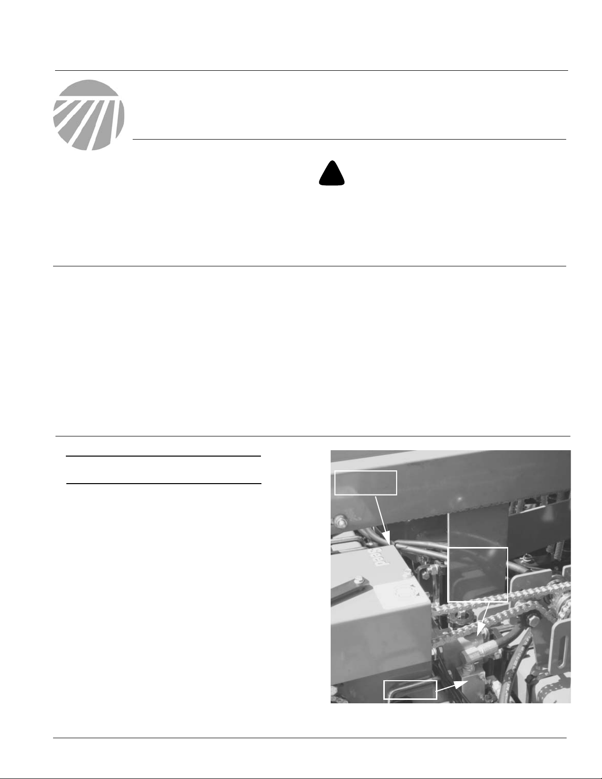
1. Locate depth stop valve mount and strok e control
valve on front left-hand side of drill directly behind the
gearbox.
Before You Start
Page 10 is a detailed listing of parts included in
the Hydraulic V alve Kit. Use this list to inventory
parts received.
T ools Required
• Basic Hand Tools
Gearbox
Depth Stop
Valve Mount
© Copyright 2005 Printed
4/27/2005
Valve
Figure 1
23153
151-120M
Page 2
Hydraulic Valve Kit
2
Refer to Figure 2
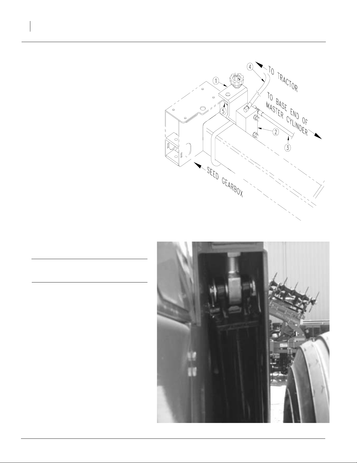
2. Disconnect hose (4) connecting valve (2) to
tractor at valve (2). Disconnect hose (3) connecting valve (2) to master cylinder at v alve
(2). Keep elbow for reuse.
3. Remove two 1/4-20 x 3" bolts holding together depth adjustment bracket (5), depth
stop valve mount(1), and strok e control
valve(2). Bolts and brac ket are located under depth stop valve mount(1). Keep valve,
bolts, and spacer tubes for reuse.
Great Plains Mfg., Inc.
Refer to Figure 3
Important! T o disconnect hose from valv e to
master cylinder at master cylinder, it ma y be
necessary to remove tire.
4. Remove pin to cylinder letting cylinder f all
so it is visible. If needed, remov e tire . Disconnect hose from valve to master cylinder
at master cylinder. Discard hose.
Figure 2
23145
Figure 3
151-120M 4/27/2005
23150
Page 3
Great Plains Mfg., Inc.
Refer to Figure 4
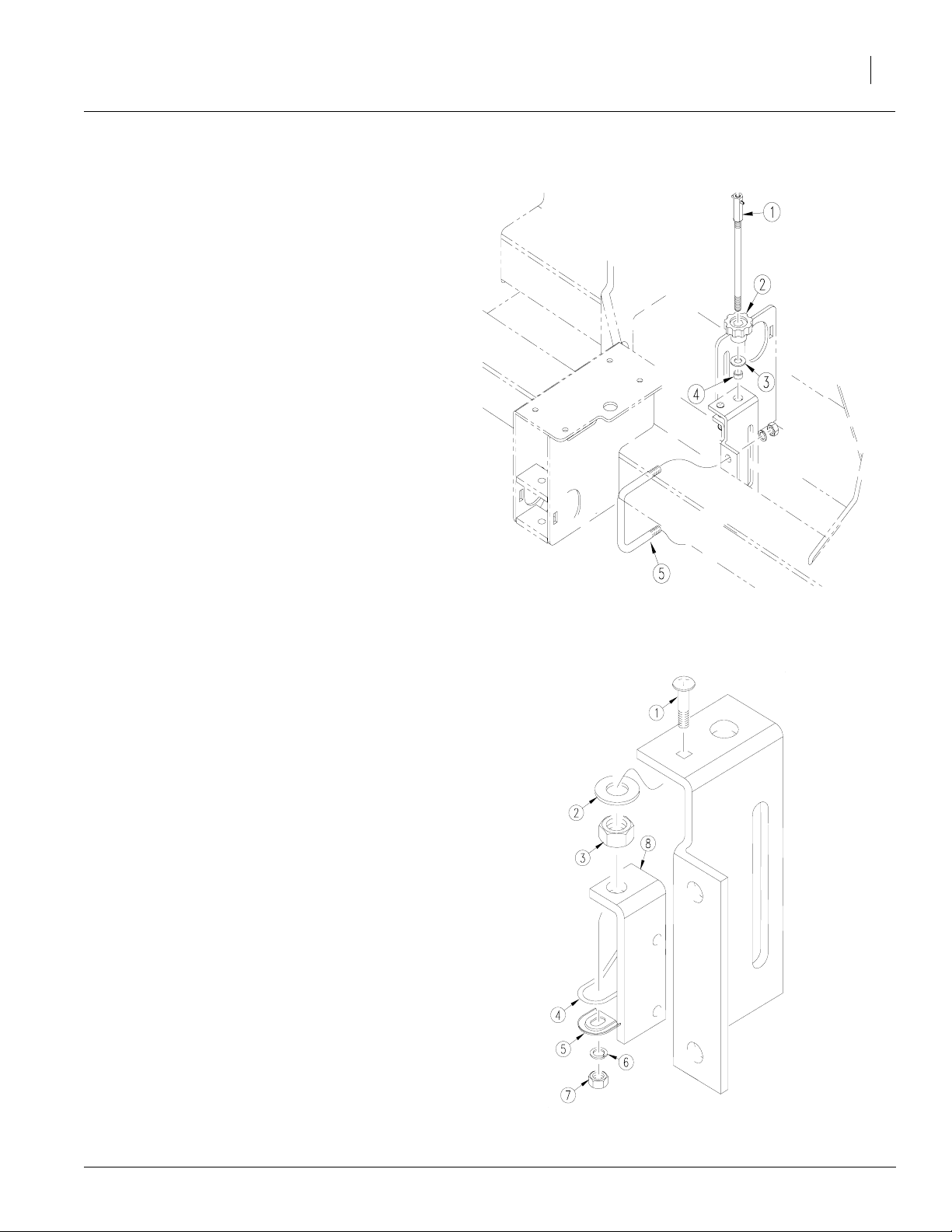
5. Unscrew screw adjustment rod (1) from knob (2)
and remove knob (2), washer (3), and spacer tube
(4) from top of depth stop valve mount. Keep all
pieces for reuse.
6. Remove U-bolt (5) holding depth stop valve
mount in place. Keep for reuse.
Installation Instructions
3
Refer to Figure 5
7. Unscrew 1/4-20 x 3/4" bolt (1) from top of
mount removing washer (2), nut he x (3),
depth adjustment bracket (8), tension spring
retainer (4), screw spring adjustment (5),
washer (6), and nut hex (7). Discard depth
stop valve mount and depth adjustment
bracket. Keep all other pieces for reuse.
Figure 4
23146
4/27/2005
Figure 5
23147
151-120M
Page 4

Hydraulic Valve Kit
4
Refer to Figure 6
8. Replace bolt (9), new depth adjustment brack et
(3), washer (8), nut hex (7), tension spring retainer (4), screw spring adjustment (1), washer
(5), and nut hex (6) on new depth stop valve
mount (2) provided in kit.
Great Plains Mfg., Inc.
Refer to Figure 7
9. Align knob (4), washer (2), and spacer tube
(3). Screw into top of mount (5) using screw
adjustment rod (1). Secure with flat washer
and nut hex.
10. Bolt new depth stop adjustment brack et (8)
to depth stop valve mount (5) and v alve (7)
using bolts (6) removed in step 1.
Figure 6
23155
Figure 7
151-120M 4/27/2005
23149
Page 5

Great Plains Mfg., Inc.
Refer to Figure 8
11. Attach valve mount (1) on tubing on right-hand
side of drill next to native grass gearbox mount
(4) using the U-bolt (2) from step 5.
12. Connect hose (5) leading to tractor to valve (6).
13. Add elbow fitting (3) to new hose (7) provided in
kit. Connect to valve (6) and master cylinder.
Where necessary , tie do wn with cab le ties .
Installation Instructions
5
4/27/2005
Figure 8
23148
151-120M
Page 6

Hydraulic Valve Kit
6
Refer to Figure 9
14. Cut flex hose in approximately half. To prevent damage to hydraulic hoses attach one
half of hose to slots on both sides of drill
frame.
NOTE: If additional clearance is needed, the slot
may be enlarged to 1 3/4" x 4".
Great Plains Mfg., Inc.
Figure 9
151-120M 4/27/2005
23158
Page 7

Great Plains Mfg., Inc.
Refer to Figure 10
15. Replace cylinder and pin securing cylinder in
place. If removed, put tire on.
Installation Instructions
7
16. Place depth stop adjustment decal on righthand side of drill on native grass gearbox.
4/27/2005
Figure 10
23150
151-120M
Page 8

Hydraulic Valve Kit
8
Hydraulic Schematics
Great Plains Mfg., Inc.
Hydrualic Routing
706NT 7 1/2" & 8" S/N 1040WW-
151-120M 4/27/2005
23156
Page 9

Great Plains Mfg., Inc.
Installation Instructions
9
4/27/2005
Hydraulic Routing
1006NT & 706NT 7"
23157
151-120M
Page 10

Great Plains Mfg., Inc.
151-119A Hydraulic V alve Kit
Your kit includes:
Qty. Part No. Part Description
1 152-378D DEPTH STOP VALVE MOUNT
1 152-179H DEPTH ADJUSTMENT BRACKET WLMT
1.5’ 817-044C FLEX GUARD HOSE .594 IDX.41
1 841-023C HH1/2R2 112 3/4FJIC 3/4MORB
1 811-040C EL 45 3/4MJIC 3/4FJIC
4 800-082C CABLE TIE .31X21.5 6DIA 120LB
1 151-120M HYDRAULIC VALVE KIT MANUAL
1 818-695C DECAL
Installation Instructions
10
151-120M4/27/2005
 Loading...