

Page 1
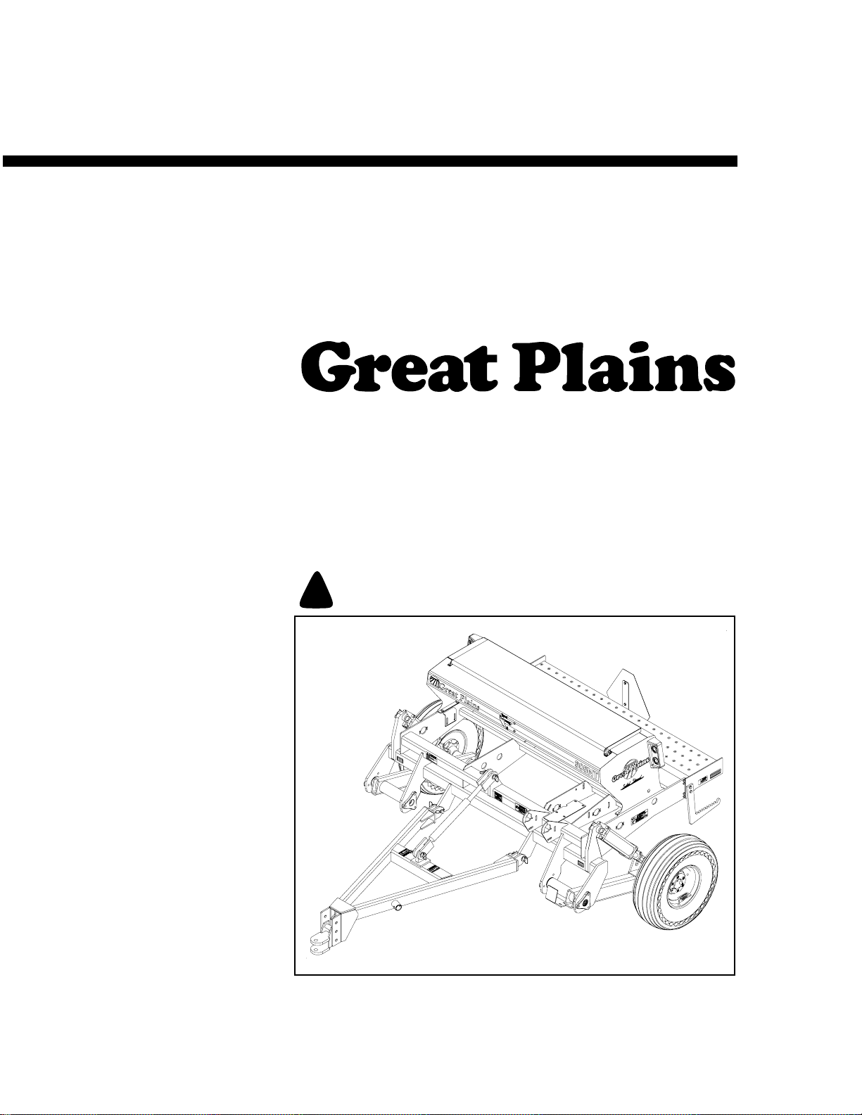
Predelivery Manual
605NT and 606NT
6-Foot No-Till Drill
Manufacturing, Inc.
www.greatplainsmfg.com
Read the operator’s manual entirely. When you see this symbol, the subsequent
instructions and warnings are serious - follow without exception. Your life and
!
the lives of others depend on it!
18557
Cover illustration may show optional equipment not supplied with standard unit.
© Copyright 2009 Printed
8/19/09
151-061Q
Page 2

Table of Contents
Important Safety Information . . . . . . . . . . . . 1
Safety Rules. . . . . . . . . . . . . . . . . . . . . . . . 1
Introduction. . . . . . . . . . . . . . . . . . . . . . . . . . . 2
Description of Unit . . . . . . . . . . . . . . . . . . . 2
Intended Usage . . . . . . . . . . . . . . . . . . 2
Models Covered . . . . . . . . . . . . . . . . . 2
Using This Manual . . . . . . . . . . . . . . . . . . . 2
Definitions . . . . . . . . . . . . . . . . . . . . . . 3
Assembly and Setup Assistance . . . . . . . . 3
Assembly. . . . . . . . . . . . . . . . . . . . . . . . . . . . . 4
Tools Required . . . . . . . . . . . . . . . . . . . . . . 4
Pre-Assembly Checklist . . . . . . . . . . . . . . . 4
Tongue Assembly. . . . . . . . . . . . . . . . . . . . 5
Hydraulic Hoses and Wiring. . . . . . . . . . . . 6
Setup. . . . . . . . . . . . . . . . . . . . . . . . . . . . . . . . . 7
Hitching Tractor to Drill . . . . . . . . . . . . . . . . 7
Hydraulic Hose Hookup. . . . . . . . . . . . . . . . 8
Rephasing Cylinders . . . . . . . . . . . . . . . . . . 8
Bleeding Hydraulics. . . . . . . . . . . . . . . . . . . 8
Appendix . . . . . . . . . . . . . . . . . . . . . . . . . . . .10
Torque Values Chart for Common Bolt
Sizes . . . . . . . . . . . . . . . . . . . . . . . . . . . . . 10
Tire Inflation Chart. . . . . . . . . . . . . . . . . . . 11
Hydraulic Schematic . . . . . . . . . . . . . . . . . 11
© Copyright 2000-2009 All rights Reserved
Great Plains Manufacturing, Inc. provides this publication “as is” without warranty of any kind, either expressed or implied. While every precaution has been taken in the
preparation ofthis manual,Great PlainsManufacturing, Inc.assumes noresponsibility for errors or omissions. Neither is any liability assumed fordamages resultingfrom
the use of the information contained herein. GreatPlains Manufacturing, Inc. reserves theright to revise and improve its products as it sees fit. Thispublication describes
the state of this product at the time of its publication, and may not reflect the product in the future.
The following are trademarks of Great Plains Mfg., Inc.: Application Systems, Ausherman, Land Pride, Great Plains
All other brands and product names are trademarks or registered trademarks of their respective holders.
151-061Q 8/19/2009
Great Plains Manufacturing, Incorporated Trademarks
Printed in the United States of America.
Page 3

Important Safety Information
For your safety, thoroughly read “Important Safety
Information” in the 6’ No-Till Drill operator’s
manual.
Safety Rules
Most accidents are the result of negligence, carelessness or failure to follow safety precautions.
Although your implement is designed with many
built-in safety features, safety precautions are
mandatory to prevent accidents.
Look for Safety Symbol
The SAFETY ALERT SYMBOL indicates there is
a potential hazard to personal safety involved and
extra safety precaution must be taken. When you
see this symbol, be alert and carefully read the
message that follows it. In addition to design and
configuration of equipment, hazard control and
accident prevention are dependent upon the
awareness, concern, prudence and proper training of personnel involved in the operation,
transport, maintenance and storage of
equipment.
Important Safety Information
!
1
8/19/2009
Be Aware of Signal Words
Signal words designate a degree or level of hazard seriousness.
DANGER indicates an imminently hazardous situation which, if not avoided, will result in death or
serious injury. This signal word is limited to the
most extreme situations, typically for machine
components that, for functional purposes, cannot
be guarded.
WARNING indicates a potentially hazardous situation which, if not avoided, could result in death or
serious injury, and includes hazards that are exposed when guards are removed. It may also be
used to alert against unsafe practices.
CAUTION indicates a potentially hazardous situation which, if not avoided, may result in minor or
moderate injury. It may also be used to alert
against unsafe practices.
DANGER
!
WARNING
!
CAUTION
!
151-061Q
Page 4
605NT and 606NT
2
Introduction
Great Plains Manufacturing wants you to be satisfied with any new machine delivered by the Great
Plains Trucking network. To ease the assembly
task and produce a properly working machine,
read this entire manual before assembling or setting up new equipment.
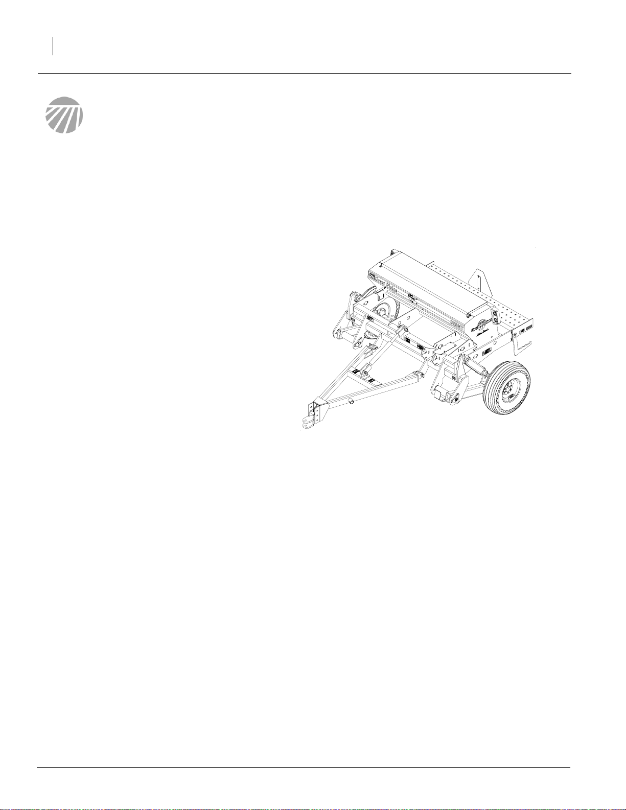
Description of Unit
The 605NT and 606NT are a 6 foot pull-type
seeding implement, designed for no-till conditions. Coulters mounted on the drill frame cut
channels for the opener disks. The opener disks
clear away crop residue and open a seed trench.
Seed tubes between the opener disks place seed
in the trench, and press wheels firm soil over the
seed. The press wheels also gauge opener depth.
Intended Usage
Use this drill to seed grasses or production-agriculture crops or to seed over existing grass
stands.
Models Covered
605NT
606NT
Using This Manual
This manual was written to help you assemble
and prepare the new machine for the customer.
The manual includes instructions for assembly
and setup. Read this manual and follow the recommendations for safe, efficient and proper
assembly and setup.
An operator’s manual is also provided with the
new machine. Read and understand “Important
Safety Information” and “Operating Instructions”
in the operator’s manual before assembling the
machine. As a reference, keep the operator’s
manual on hand while assembling.
The information in this manual is current at printing. Some parts may change to assure top
performance.
18557
605NT
151-061Q
8/19/2009
Page 5

Definitions
The following terms are used throughout this
manual.
Right and left as used in this manual are determined by facing the direction the machine will
travel while in use unless otherwise stated.
IMPORTANT: A crucial point of information
about the preceding topic. For safe and correct
operation, read and follow the directions provided before continuing.
NOTE: Useful information about the preceding
topic.
Assembly and Setup Assistance
To order additional copies of predelivery instructions or operator’s and parts manuals, write to the
following address. Include model numbers in all
correspondence.
Introduction
3
If you do not understand any part of this manual or
have other assembly or setup questions, assistance is available. Contact
Product Support
Great Plains Mfg. Inc., Service Department
P.O. Box 5060
Salina, KS 67402-5060
8/19/2009
151-061Q
Page 6

605NT and 606NT
4
The following headings are step-by-step instructions for assembling the 605NT and 606NT. Begin
with “Tools Required” and “Pre-Assembly Checklist” to make sure you have all necessary parts
and equipment. Follow each step to make the job
as quick and safe as possible and produce a properly working machine.
The 605NT and 606NT are shipped via flat bed
truck. It is the dealer’s responsibility to unload the
new machine. Unload all equipment before beginning assembly. Donot attemptany assembly work
while the 605NT or 606NT is on the truck.
Assembly
Tools Required
• Fork-lift, overhead hoist or loader
• General hand tools
Pre-Assembly Checklist
1. Before assembling, read and understand “Important Safety Information,” beginning on
page 1.
2. Have at least two people on hand while assembling.
3. Make sure assembly area is level and free of
obstructions (preferably an open concrete area).
4. Have all major components.
5. Have all fasteners and pins shipped with
605NT and 606NT.
IMPORTANT: If a pre-assembled part or fastener is temporarily removed, remember
where it goes. Keep the parts separated.
151-061Q
6. Have a copy of the parts manual on hand. If
unsure of proper placement or use of any part
or fastener, refer to the parts manual.
7. Check that all working parts are moving freely, bolts are tight, and cotter pins are spread.
8. Check for proper tension and alignment on all
drive chains.
M
anual
Parts
8/19/2009
Page 7

9. Check that all safety decals and reflectors are
located correctly and legible. Replace if improperly located ordamaged. Refer to “Safety
Decals” in the operator’s manual.
10. Inflate tires to recommended pressure as listed on the “Tire Inflation Chart,” in operator’s
manual. Tighten wheel bolts as specified on
“Torque Values Chart,” in operator’s manual.
Tongue Assembly
See Figure 1:
1. With the aid of a fork-lift, overhead hoist or
loader, lift the tongue (1) into place to the
mounting brackets (2).
2. Pin tongue to mountings with 1 x 3-3/8 inch
hitch pins (3).
Assembly
5
3. Pin hitch turnbuckle (4) to drill frame (5) with
1 x 3-3/8 inch hitch pins (6).
8/19/2009
Figure 1
Tongue Installation
18723
151-061Q
Page 8

605NT and 606NT
6
Hydraulic Hoses and Wiring
See Figure 2:
1. Unwind hydraulic hoses and light wiring harness from drill frame.
2. Route hydraulic hoses (1) and light wiring harness (2) inside tongue as shown.
See Figure 3:
3. Plug in light harness extension (3) to wiring
harness.
4. Clamp together hydraulic hoses with plastic
hose label (4) and red and blue cable ties (5).
Figure 2
Hose and Wiring Routing
18724
18725
Figure 3
Hose and Wiring Routing
151-061Q
8/19/2009
Page 9

!
Setup
Hitching Tractor to Drill
DANGER
You may be severely injured or killed by being crushed
between the tractor and drill. Do not stand or place
any part of your body between drill and moving tractor. Stop tractor engine and set park brake before installing the hitch pin.
1. With drill lowered in field position and tongue
jack mounted as shown in Figure 4, raise or
lower tongue jack to level drill tongue.
2. With drill tongue level, adjust drill hitch on drill
tongue to match your tractor-drawbar height.
Refer to Figure 5. You can move the hitch up
or down or turn it over for a total of four different hitch heights.
Figure 4
Tongue Jack
Setup
18473
7
Figure 5
Hitch Height Adjustment
3. When drill hitch matches tractor-drawbar
height, hitch drill to tractor.
4. Securely attach drill safety chain to an anchor
on tractor capable of pulling drill.
NOTE: When hitching drill to a different tractor,
check for a difference in drawbar heights. If
heights are different, readjust hitch height accordingly.
8/19/2009
18544
151-061Q
Page 10

605NT and 606NT
!
8
Hydraulic Hose Hookup
Great Plains hydraulic hoses are color coded to
help you hookup hoses to your tractor outlets.
Hoses that go to the same remote valve are
marked with the same color.
Color Hydraulic Function
Blue Transport Lift Cylinders
To distinguish hoses onthe same hydraulic circuit,
refer to plastic hose label. Hose under extendedcylinder symbol feeds cylinder base ends. Hose
under retracted-cylinder symbol feeds cylinder
rod ends.
Rephasing Cylinders
The lift cylinders may, after a period of time, get
out of time or phase. The effects of this can be
seen when one side of the drill is running too low
or too high because its lift cylinder is either over
extended or not retracted compared to the other
lift cylinder.
Plastic
hose label
17641
Figure 6
Plastic Hose Label
To rephase the cylinders, raise drill completely
and hold tractor hydraulic lever on for a few seconds to give cylinders time to rephase.
Each time drill is raised out of ground momentarily
reverse hydraulic lever immediately after rephasing to allow cylinders to retract about 1/2 inch.
This will help in maintaining a level drill.
NOTE: Understand that having cylinders become
gradually out of time is different than having air
trapped in the system from improper bleeding.
Each condition is corrected differently.
Bleeding Hydraulics
WARNING
Escaping fluid under pressure can have sufficient pressure to penetrate the skin. Check all hydraulic lines
and fittings before applying pressure. Fluid escaping
from a very small hole can be almost invisible. Use paper or cardboard, not body parts, and wear heavy
gloves to check for suspected leaks. If injured, seek
medical assistance from a doctor that is familiar with
this type of injury. Foreign fluids in the tissue must be
surgically removed within a few hours or gangrene
will result.
151-061Q
8/19/2009
Page 11

Check that tractor hydraulic reservoir is full.
The drill lifting system is equipped with rephasing
type hydraulic cylinders that require a special procedure for bleeding air from the hydraulic circuits.
Read and follow this procedure carefully. Rephasing type cylinders will not function properly with air
in hydraulic circuit.
1. Check hydraulic fluid in tractor reservoir and
fill reservoir to proper level. Drill-system capacity is about 1 gallon. Add fluid to system as
needed. A low reservoir level may draw air
back into the system, causing jerky or uneven
cylinder movements.
2. With drill attached to tractor, jack drill up and
support frame at ends near gauge wheels.
3. With drill raised and supported, unpin cylinders from gauge wheel arms and frame. Turn
cylinders "rod end up". Wire or otherwise
safely support rod ends higher than base
ends.
Setup
9
NOTE: In order to prevent trapped air pockets, rod
end must be higher than any other part of cylinder
during bleeding operation.
4. With tractor engine idling, engage tractor hydraulics to extend cylinder rods. When cylinder rods are completely extended, hold
remote lever on for one minute.
5. Retract cylinders. Extend cylinders again and
hold remote lever on for one more minute. Repeat this step two more times to completely
bleed system.
6. Repin cylinders to drill frame and gauge
wheel arm with transport cylinder locks in
place. If any air still is trapped in either cylinder, the cylinder will have a spongy, erratic
movement and drill will not raise evenly. If
necessary, repeat bleeding process.
7. Refill tractor hydraulic fluid reservoir to its
proper level.
NOTE: After the drill is raised, a slight settling will
occur due to the action of the rephasing cylinders.
8/19/2009
151-061Q
Page 12

605NT and 606NT
10
Appendix
Torque Values Chart for Common Bolt Sizes
Bolt Head Identification
Bolt Head Identification
Bolt Size
(Inches)
1
in-tpi
1/4" - 20 7.4 5.6 11 8 16 12 M 5 X 0.8 436597
1/4" - 28 8.5 6 13 10 18 14 M 6 X 1 7 5 11 8 15 11
5/16 - 18 15 11 24 17 33 25 M 8 X 1.25 17 12 26 19 36 27
5/16" - 24 17 13 26 19 37 27 M 8 X 1 18 13 28 21 39 29
3/8" - 16 27 20 42 31 59 44 M10 X 1.5 33 24 52 39 72 53
3/8" - 24 31 22 47 35 67 49 M10 X 0.75 39 29 61 45 85 62
7/16" - 14 43 32 67 49 95 70 M12 X 1.75 58 42 91 67 125 93
7/16" - 20 49 36 75 55 105 78 M12 X 1.5 60 44 95 70 130 97
1/2" - 13 66 49 105 76 145 105 M12 X 1 90 66 105 77 145 105
1/2" - 20 75 55 115 85 165 120 M14 X 2 92 68 145 105 200 150
9/16" - 12 95 70 150 110 210 155 M14 X 1.5 99 73 155 115 215 160
9/16" - 18 105 79 165 120 235 170 M16 X 2 145 105 225 165 315 230
5/8" - 11 130 97 205 150 285 210 M16 X 1.5 155 115 240 180 335 245
5/8" - 18 150 110 230 170 325 240 M18 X 2.5 195 145 310 230 405 300
3/4" - 10 235 170 360 265 510 375 M18 X 1.5 220 165 350 260 485 355
3/4" - 16 260 190 405 295 570 420 M20 X 2.5 280 205 440 325 610 450
7/8" - 9 225 165 585 430 820 605 M20 X 1.5 310 230 650 480 900 665
7/8" - 14 250 185 640 475 905 670 M24 X 3 480 355 760 560 1050 780
1" - 8 340 250 875 645 1230 910 M24 X 2 525 390 830 610 1150 845
1" - 12 370 275 955 705 1350 995 M30 X 3.5 960 705 1510 1120 2100 1550
1-1/8" - 7 480 355 1080 795 1750 1290 M30 X 2 1060 785 1680 1240 2320 1710
1 1/8" - 12 540 395 1210 890 1960 1440 M36 X 3.5 1730 1270 2650 1950 3660 2700
1 1/4" - 7 680 500 1520 1120 2460 1820 M36 X 2 1880 1380 2960 2190 4100 3220
1 1/4" - 12 750 555 1680 1240 2730 2010
1 3/8" - 6 890 655 1990 1470 3230 2380
1 3/8" - 12 1010 745 2270 1670 3680 2710
1 1/2" - 6 1180 870 2640 1950 4290 3160
1 1/2" - 12 1330 980 2970 2190 4820 35604mm x pitch = nominal thread diameter in millimeters x thread pitch
Grade 2 Grade 5
N · m2ft-lb3N · m ft-lb N · m ft-lb mm x pitch4N · m ft-lb N · m ft-lb N · m ft-lb
Torque tolerance + 0%, -15% of torquing values. Unless otherwise specified use torque values listed above.
Grade 8
Bolt Size
(Metric)
1
in-tpi = nominal thread diameter in inches-threads per inch
5.8 8.8 10.9
Class 5.8 Class 8.8 Class 10.9
2
N· m = newton-meters
3
ft-lb= foot pounds
151-061Q
8/19/2009
Page 13

Tire Inflation Chart
Appendix
11
Tire Size Inflation
PSI
7.50 x 20" 4-Ply Drill Rib 28 11L x 15" 6-Ply Rib Implement 28
9.0 x 22.5 10-Ply Highway Service 70 70 11L x 15" 12-Ply Rib Implement 52
9.0 x 24" 8-Ply Rib Implement 40 12.5L x 15" 8-Ply Rib Implement 36
9.5L x 15" 6-Ply Rib Implement 32 12.5L x 15" 10-Ply Rib Implement 44
9.5L x 15" 8-Ply Rib Implement 44 16.5L x 16.1" 10-Ply Rib Implement 36
9.5L x 15" 12-Ply Rib Implement 60 41 x 15" x 18 - 22-Ply Rib Implement 44
Tire Size Inflation
PSI
Hydraulic Schematic
8/19/2009
18676
151-061Q
Page 14

Great Plains Manufacturing, Inc.
Corporate Office: PO. Box 5060
Salina, Kansas 67402-5060 USA
 Loading...