

Page 1
Table of Contents Index
Operator Manual
3P606NT, 606NT
2007+ 3P605NT and 605NT
6-Foot No-Till Drills
Manufacturing, Inc.
www.greatplainsmfg.com
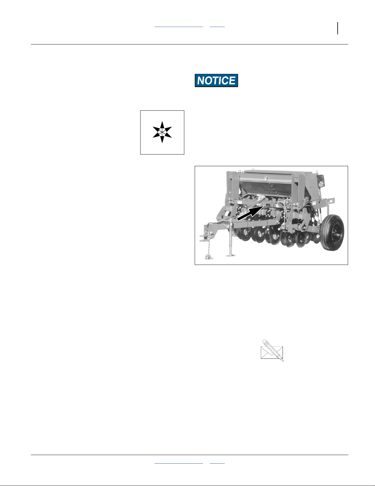
Read the operation manual entirely. When you see this symbol, the
subsequent instructions and warnings are serious - follow without
exception. Your life and the lives of others depend on it!
25106
25105
Illustrations may show optional equipment not supplied with standard unit.
ORIGINAL INSTRUCTIONS
© Copyright 2014 Printed 2014-02-10 151-061M
Table of Contents Index
EN
Page 2

Table of Contents Index
Table of Contents Index
Page 3

Great Plains Manufacturing, Inc. Cover Index iii
Table of Contents
Important Safety Information ......................................1
Safety Decals .................................................................6
Introduction ................................................................12
Description of Unit ........................................................12
Intended Usage ........................................................12
Models Covered .......................................................12
Document Family......................................................12
Using This Manual........................................................13
Owner Assistance ........................................................13
Preparation and Setup ...............................................14
Pre-Setup Checklist......................................................14
Hitching Tractor to Drill.................................................14
Hitching Model 3P605NT or 3P606NT ..................... 14
Hitching Model 605NT or 606NT..............................15
Hydraulic Hose Hookup (605NT or 606NT)..........16
Electrical Connections..................................................16
Height and Leveling the Drill ........................................17
Height Setup: Model 3P605NT or 3P606NT ............17
Adjusting 3-Point Height .......................................17
Height Setup: Model 605NT or 606NT ..................... 18
Set Tool Bar Height ..............................................18
Level Model 605NT or 606NT ..............................18
Operation Instructions...............................................19
Pre-Start Checklist .......................................................19
Transporting 3P605NT or 3P606NT.............................20
Use an Adequate Tractor (3-Point)...........................20
3P605NT or 3P606NT Example Weights.................20
Transporting 605NT or 606NT .....................................21
Use an Adequate Tractor (Pull-Type)....................... 21
605NT or 606NT Example Weights.......................... 21
Use Transport Locks ................................................22
Loading Seed ............................................................... 24
Main Seed Box Loading ..........................................24
Loading Native Grass Box....................................... 24
Loading Small Seeds Box .......................................24
Field Operation.............................................................25
Re-Phasing Cylinders............................................... 25
Acremeter Operation ....................................................26
Parking .........................................................................27
Storage.........................................................................28
Adjustments................................................................29
Frame Weight Adjustment............................................30
Coulter Adjustments..................................................... 31
Coulter Depth ........................................................... 31
Coulter Down-Force ................................................. 32
Drive Clutch Adjustment .............................................. 32
05/06 Series Row Unit Adjustments ............................ 33
Opener Spring..........................................................34
Disc Blade Adjustments ........................................... 35
Disc Scraper Adjustment.......................................... 36
Seed Firmer Adjustments......................................... 37
Seed-Lok® Lock-Up (Option) ............................... 37
Keeton® Seed Firmer Adjustment (Option) .......... 37
Small Seeds Tube Adjustment (Option)................... 38
Opener Depth (Press Wheel Height) ....................... 38
Troubleshooting......................................................... 39
Maintenance and Lubrication ................................... 42
Maintenance ................................................................ 42
Drive Idler Adjustment (605NT or 606NT)................ 43
Seed Clean-Out ....................................................... 43
Main Box Clean-Out............................................. 43
Native Grass Box Clean-Out................................ 44
Small Seeds Box Clean-Out ................................ 44
Seed Flap Replacement .............................................. 45
Current Drill Model Flap ........................................... 45
Older Drill Model Flap .............................................. 45
Bleeding Hydraulics ................................................. 46
Chain Maintenance .................................................. 47
Chain Slack .......................................................... 47
Gearbox Maintenance..............................................47
Lubrication and Scheduled Maintenance..................... 48
Options ....................................................................... 53
Seed-Lok® Seed Firmer........................................... 59
Appendix A - Reference Information........................ 60
Specifications and Capacities ...................................... 60
Tire Pressures.............................................................. 60
Torque Values Chart.................................................... 61
Hydraulic Diagram ....................................................... 62
Drive System Diagrams ............................................... 63
Appendix B - Pre-Delivery......................................... 67
Appendix C - Accessory Installation........................ 68
Carbide Disc Scraper Installation................................. 68
Warranty ..................................................................... 69
Index............................................................................ 71
© Copyright 2006, 2007, 2008, 2009, 2011, 2012, 2014 All rights Reserved
Great Plains Manufacturing, Inc. provides this publication “as is” without warranty of any kind, either expressed or implied. While every precaution has been
taken in the preparation of this manual, Great Plains Manufacturing, Inc. assumes no responsibility for errors or omissions. Neither is any liability assumed for
damages resulting from the use of the information contained herein. Great Plains Manufacturing, Inc. reserves the right to revise and improve its products as
it sees fit. This publication describes the state of this product at the time of its publication, and may not reflect the product in the future.
2014-02-10 Cover Index 151-061M
Trademarks of Great Plains Manufacturing, Inc. include: Singulator Plus, Swath Command, Terra-Tine.
Registered Trademarks of Great Plains Manufacturing, Inc. include:
Air-Pro, Clear-Shot, Discovator, Great Plains, Land Pride, MeterCone, Nutri-Pro, Seed-Lok, Solid Stand,
Terra-Guard, Turbo-Chisel, Turbo-Chopper, Turbo Max, Turbo-Till, Ultra-Till, Ver ti-Till, Whirlfilter, Yield-Pro.
Brand and Product Names that appear and are owned by others are trademarks of their respective owners.
Page 4

iv 3P605NT, 3P606NT, 605NT & 606NT Table of Contents Index Great Plains Manufacturing, Inc.
151-061M Table of Contents Index 2014-02-10
Page 5
Great Plains Manufacturing, Inc. Table of Contents Index 1
Important Safety Information
Look for Safety Symbol
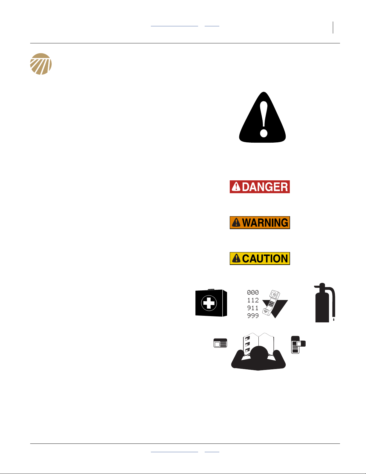
The SAFETY ALERT SYMBOL indicates there is a
potential hazard to personal safety involved and extra
safety precaution must be taken. When you see this
symbol, be alert and carefully read the message that
follows it. In addition to design and configuration of
equipment, hazard control and accident prevention are
dependent upon the awareness, concern, prudence and
proper training of personnel involved in the operation,
transport, maintenance and storage of equipment.
Be Aware of Signal Words
Signal words designate a degree or level of hazard
seriousness.
DANGER, and the color Safety Red, indicate an
imminent hazard which, if not avoided, will result in death
or serious injury. This signal word is limited to the most
extreme situations, typically for machine components
that, for functional purposes, cannot be guarded.
WARNING, and the color Safety Orange, indicate a
potential hazard which, if not avoided, could result in
death or serious injury, and includes hazards that are
exposed when guards are removed. It may also be used
to alert against unsafe practices.
CAUTION, and the color Safety Yellow, indicate a
potential hazard which, if not avoided, may result in
minor or moderate injury. It may also be used to alert
against unsafe practices.
Prepare for Emergencies
▲ Be prepared if a fire starts
▲ Keep a first aid kit and fire extinguisher handy.
▲ Keep emergency numbers for doctor, ambulance, hospital
and fire department near phone.
Be Familiar with Safety Decals
▲ Read and understand “Safety Decals” on page 6,
thoroughly.
▲ Read all instructions noted on the decals.
▲ Keep decals clean. Replace damaged, faded and illegible
decals.
2014-02-10 Table of Contents Index 151-061M
Page 6

2 3P605NT, 3P606NT, 605NT & 606NT Table of Contents Index Great Plains Manufacturing, Inc.
Wear Protective Equipment
▲ Wear protective clothing and equipment.
▲ Wear clothing and equipment appropriate for the job. Avoid
loose-fitting clothing.
▲ Because prolonged exposure to loud noise can cause
hearing impairment or hearing loss, wear suitable hearing
protection such as earmuffs or earplugs.
▲ Because operating equipment safely requires your full
attention, avoid wearing entertainment headphones while
operating machinery.
Handle Chemicals Properly
Agricultural chemicals can be dangerous. Improper use
can seriously injure persons, animals, plants, soil and
property.
▲ Do not use liquid seed treatments with the 3P606NT or
606NT.
▲ Read and follow chemical manufacturer’s instructions.
▲ Wear protective clothing.
▲ Handle all chemicals with care.
▲ Avoid inhaling smoke from any type of chemical fire.
▲ Never drain, rinse or wash dispensers within 100 feet
(30 m) of a freshwater source, nor at a car wash.
▲ Store or dispose of unused chemicals as specified by
chemical manufacturer.
▲ Dispose of empty chemical containers properly. Laws
generally require power rinsing or rinsing three times,
followed by perforation of the container to prevent re-use.
Avoid High Pressure Fluids
(Model 605NT or 606NT only)
Escaping fluid under pressure can penetrate the skin,
causing serious injury.
▲ Avoid the hazard by relieving pressure before disconnecting
hydraulic lines.
▲ Use a piece of paper or cardboard, NOT BODY PARTS, to
check for suspected leaks.
▲ Wear protective gloves and safety glasses or goggles when
working with hydraulic systems.
▲ If an accident occurs, seek immediate medical attention
from a physician familiar with this type of injury.
151-061M Table of Contents Index 2014-02-10
Page 7
Great Plains Manufacturing, Inc. Table of Contents Index Important Safety Information 3
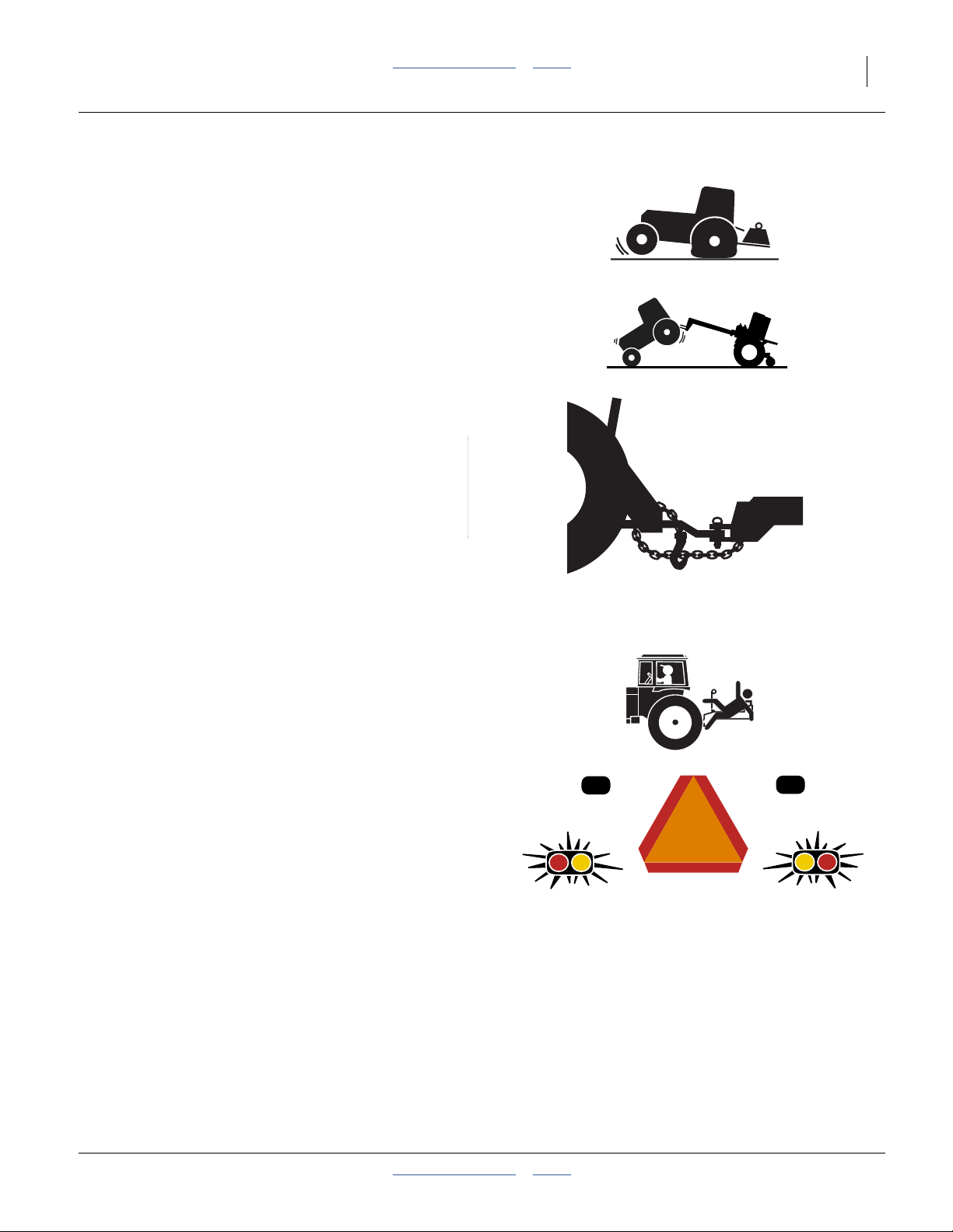
Use an Adequate Tractor
Model 3P605NT or 3P606NT only:
▲ Ensure that the tractor is rated for, and correctly ballasted
for the drill’s 3-point loading. Check that drill plus ballast
does not exceed the tractor’s capability.
▲ Avoid transport with material loaded in boxes.
Model 605NT or 606NT only:
▲ Ensure that the tractor weighs at least
(including the weight of any Options and materials).
▲ Avoid transport with material loaded in boxes.
2
⁄3(67%) of the drill
Use A Safety Chain
(Model 605NT or 606NT only)
▲ Use a safety chain to help control drawn machinery should
it separate from tractor drawbar.
▲ Use a chain with a strength rating equal to or greater than
the gross weight of towed machinery.
▲ Attach chain to tractor drawbar support or other specified
anchor location. Allow only enough slack in chain to permit
turning.
▲ Replace chain if any links or end fittings are broken,
stretched or damaged.
▲ Do not use safety chain for towing.
Keep Riders Off Machinery
Riders obstruct the operator’s view. Riders could be
struck by foreign objects or thrown from the machine.
▲ Never allow children to operate equipment.
▲ Keep all bystanders away from machine during operation.
Use Safety Lights and Devices
Slow-moving tractors and towed implements can create
a hazard when driven on public roads. They are difficult
to see, especially at night.
▲ Use flashing warning lights and turn signals whenever
driving on public roads.
▲ Use lights and devices provided with implement
2014-02-10 Table of Contents Index 151-061M
Page 8
4 3P605NT, 3P606NT, 605NT & 606NT Table of Contents Index Great Plains Manufacturing, Inc.
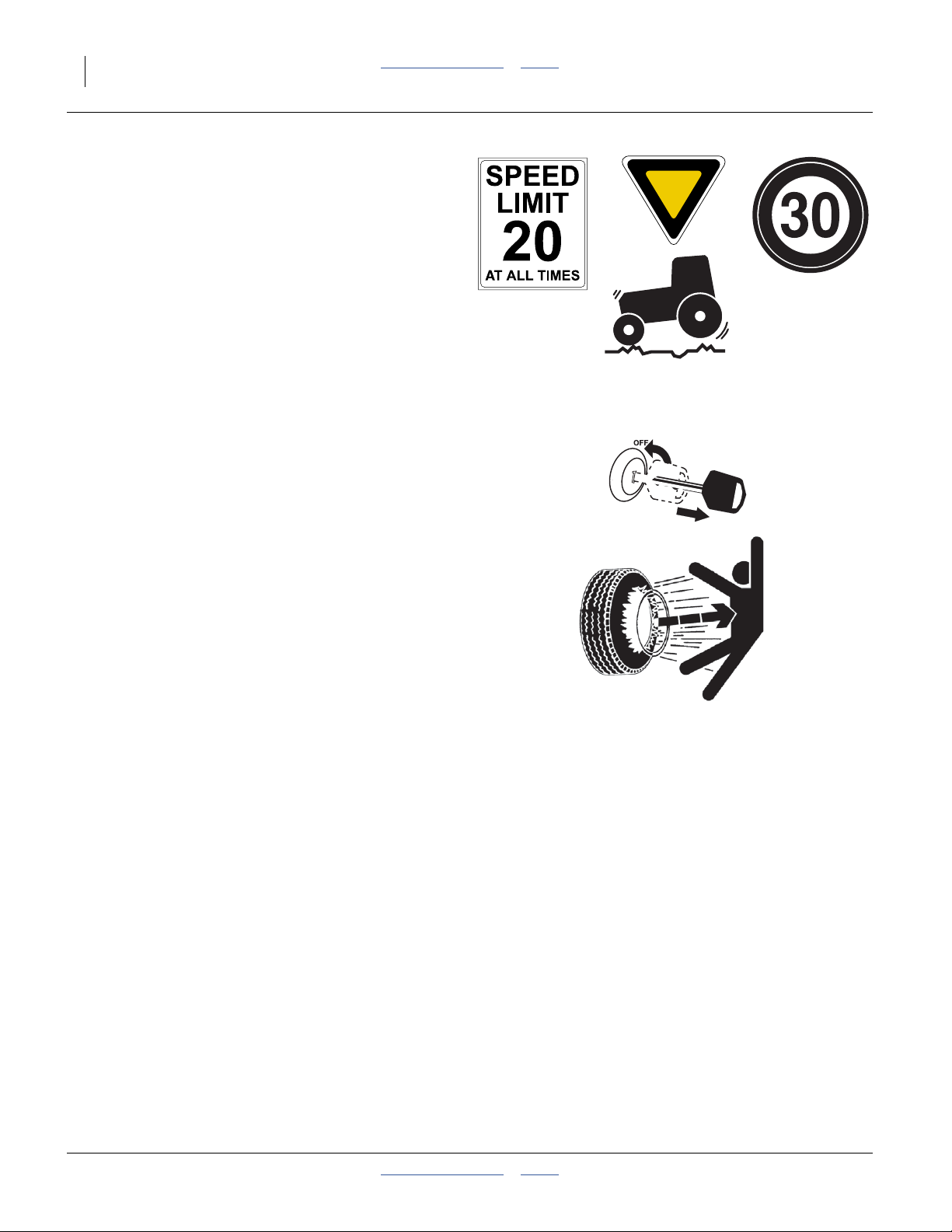
Transport Machinery Safely
Maximum transport speed for the implement on its own
tires is 20 mph (30 kph). Rough terrain may require a
slower speed. Sudden braking can cause a towed load to
swerve and upset.
▲ Do not exceed 20 mph (30 kph). Travel only at a speed
which allows adequate control of steering and stopping.
▲ Comply with state and local laws.
▲ Carry reflectors or flags to mark drill in case of breakdown
on the road.
▲ 3-point implements reduce weight on steering tires. Verify
that tractor is correctly ballasted. Watch for signs of poor
steering traction.
Shutdown and Storage
▲ Park on level ground.
▲ Unhitch and store the drill in an area where children
normally do not play.
Tire Safety
Tire changing can be dangerous and should be
performed by trained personnel using correct tools and
equipment.
▲ When inflating tires, use a clip-on chuck and extension hose
long enough for you to stand to one side–not in front of or
over tire assembly. Use a safety cage if available.
▲ When removing and installing wheels, use wheel-handling
equipment adequate for weight involved.
151-061M Table of Contents Index 2014-02-10
Page 9
Great Plains Manufacturing, Inc. Table of Contents Index Important Safety Information 5
Practice Safe Maintenance
▲ Understand procedure before doing work. Use proper
tools and equipment. Refer to this manual.
▲ Work in a clean, dry area.
▲ Lower the drill, put tractor in park, turn off engine, and
remove key before performing maintenance. If work must
be performed with implement raised, use blocks or
jackstands rated for the drill weight.
▲ Make sure all moving parts have stopped and all system
pressure is relieved.
▲ Allow drill to cool completely.
▲ Disconnect battery ground cable (-) before servicing or
adjusting electrical systems.
▲ Welding: Disconnect battery ground. Avoid fumes from
heated paint.
▲ Inspect all parts. Make sure parts are in good condition
and installed properly.
▲ Remove buildup of grease, oil or debris.
▲ Remove all tools and unused parts from drill before
operation.
Safety At All Times
Thoroughly read and understand the instructions in this
manual before operation. Read all instructions noted on
the safety decals.
▲ Be familiar with all drill functions.
▲ Operate machinery from the driver’s seat only.
▲ Do not leave drill unattended with tractor engine running.
▲ Do not stand between the moving tractor and drill during
hitching.
▲ Keep hands, feet and clothing away from power-driven
parts.
▲ Wear snug-fitting clothing to avoid entanglement with
moving parts.
▲ Make sure all persons are clear of working area.
2014-02-10 Table of Contents Index 151-061M
Page 10
6 3P605NT, 3P606NT, 605NT & 606NT Table of Contents Index Great Plains Manufacturing, Inc.
Safety Decals
Safety Reflectors and Decals
Your implement comes equipped with all lights, safety
reflectors and decals in place. They were designed to
help you safely operate your implement.
▲ Read and follow decal directions.
▲ Keep lights in operating condition.
▲ Keep all safety decals clean and legible.
▲ Replace all damaged or missing decals. Order new decals
from your Great Plains dealer. Refer to this section for
proper decal placement.
▲ When ordering new parts or components, also request
corresponding safety decals.
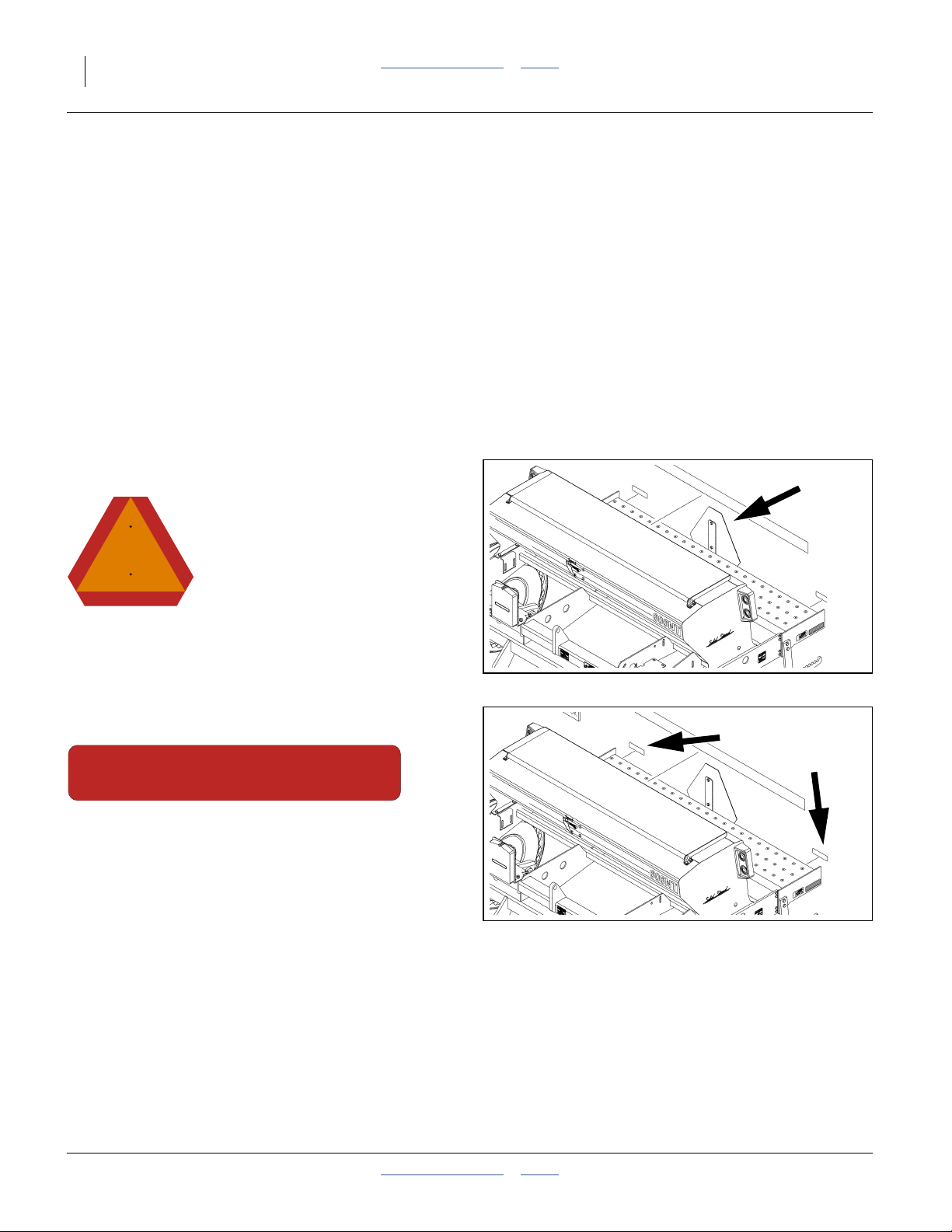
Reflector: Slow Moving Vehicle (SMV)
818-055C
To install new decals:
1. Clean the area on which the decal is to be placed.
2. Peel backing from decal. Press firmly on surface,
being careful not to cause air bubbles under decal.
At center of walkboard;
1 total
See transport topic on page 20 or page 21.
Reflectors: Red
838-266C
On rear face of walkboard, left and right ends;
2 total
See transport topic on page 20 or page 21.
32693
32693
151-061M Table of Contents Index 2014-02-10
Page 11
Great Plains Manufacturing, Inc. Table of Contents Index Important Safety Information 7
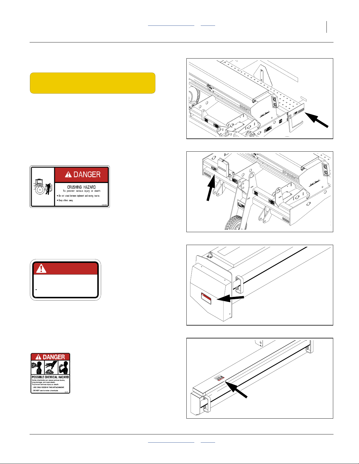
Reflectors: Amber
838-266C
On side frames at walkboard ends;
2 total
See transport topic on page 20 or page 21.
Danger: Hitch Crush
818-590C
(3P605NT and 3P606NT only)
Front face, each end of top front tool bar;
2 total
32693
32695
Danger: Moving Chain (Option)
818-518C
DANGER
MOVING CHAIN HAZARD
To prevent serious injury from moving chain:
DO NOT operate with inclosure missing
(optional Native Grass box)
On chain guard of Native Grass option box (left end);
1 total
Danger: Possible Chemical Hazard (Option)
838-467C
(with Small Seeds Option only)
Under lid;
1 total
818-518C
MOVING CHAIN HAZARD
DANGER
To prevent serious injury from moving chain:
DO NOT operate with inclosure missing
818-518C
32700
32696
2014-02-10 Table of Contents Index 151-061M
Page 12
8 3P605NT, 3P606NT, 605NT & 606NT Table of Contents Index Great Plains Manufacturing, Inc.
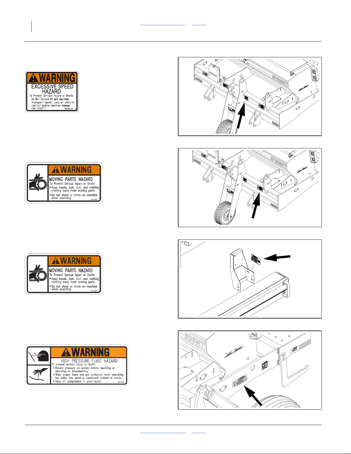
Warning: Speed
818-337C
On front face, upper front frame tube, left of center;
1 total
32695
See transport topic on page 20 or page 21.
Warning: Moving Parts (standard)
818-860C
On front face, upper front frame tube, below gearbox;
1 total
Warning: Moving Parts (Option)
818-860C
(with Small Seeds Option only)
On front face, upper front frame tube, below gearbox;
1 total
Warning: High Pressure Fluid
838-094C
32695
32696
(605NT and 606NT only)
On side frames, near cylinder;
2 total
151-061M Table of Contents Index 2014-02-10
32693
Page 13
Great Plains Manufacturing, Inc. Table of Contents Index Important Safety Information 9
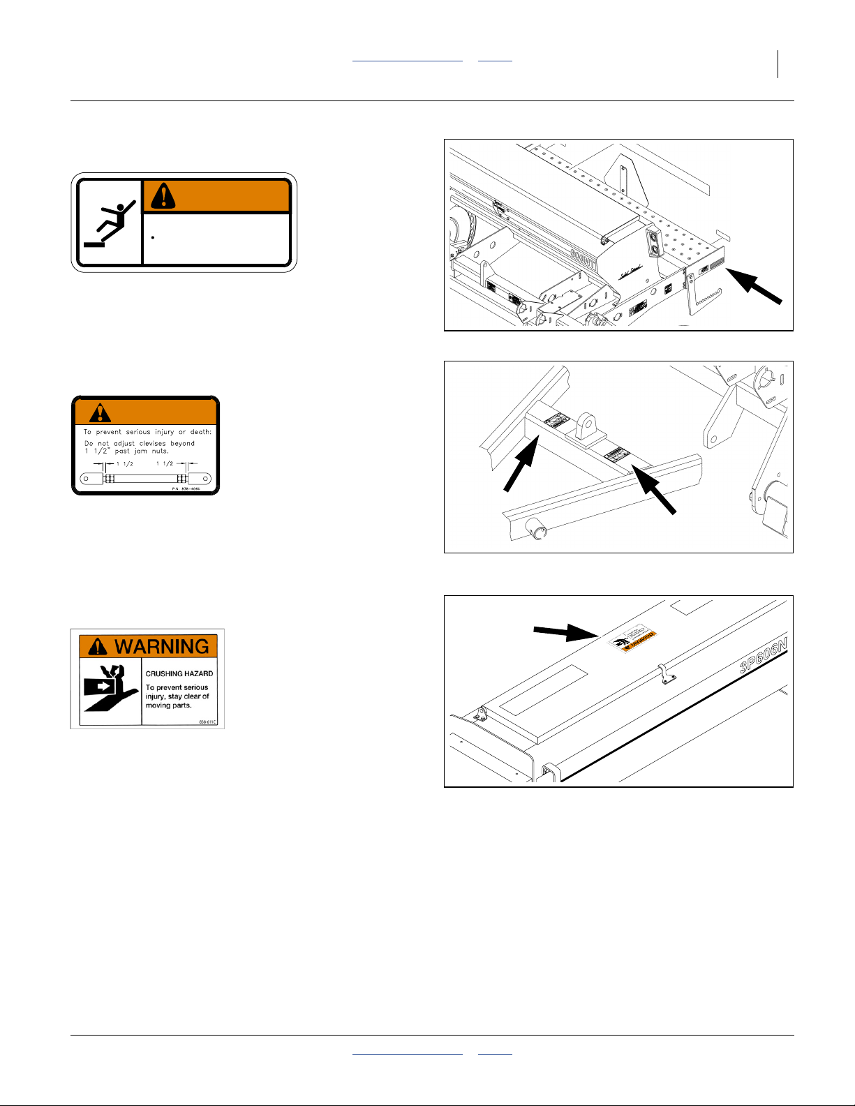
Warning: Falling Hazard
838-102C
WARNING
To avoid serious injury or death:
Watch your step when climbing ladder or
walking on walkboard.
On side frames at walkboard ends;
2 total
See “Loading Seed” on page 24.
Warning: Clevis Adjustment
838-406C
WARNING
(605NT and 606NT only)
On tongue cross-tube near turnbuckle;
2 total
See “Height and Leveling the Drill” on page 17.
838-102C
32693
32693
Warning: Crushing (Option)
838-611C
(optional Native Grass box)
On underside of lid;
1 total
32700
2014-02-10 Table of Contents Index 151-061M
Page 14
10 3P605NT, 3P606NT, 605NT & 606NT Table of Contents Index Great Plains Manufacturing, Inc.
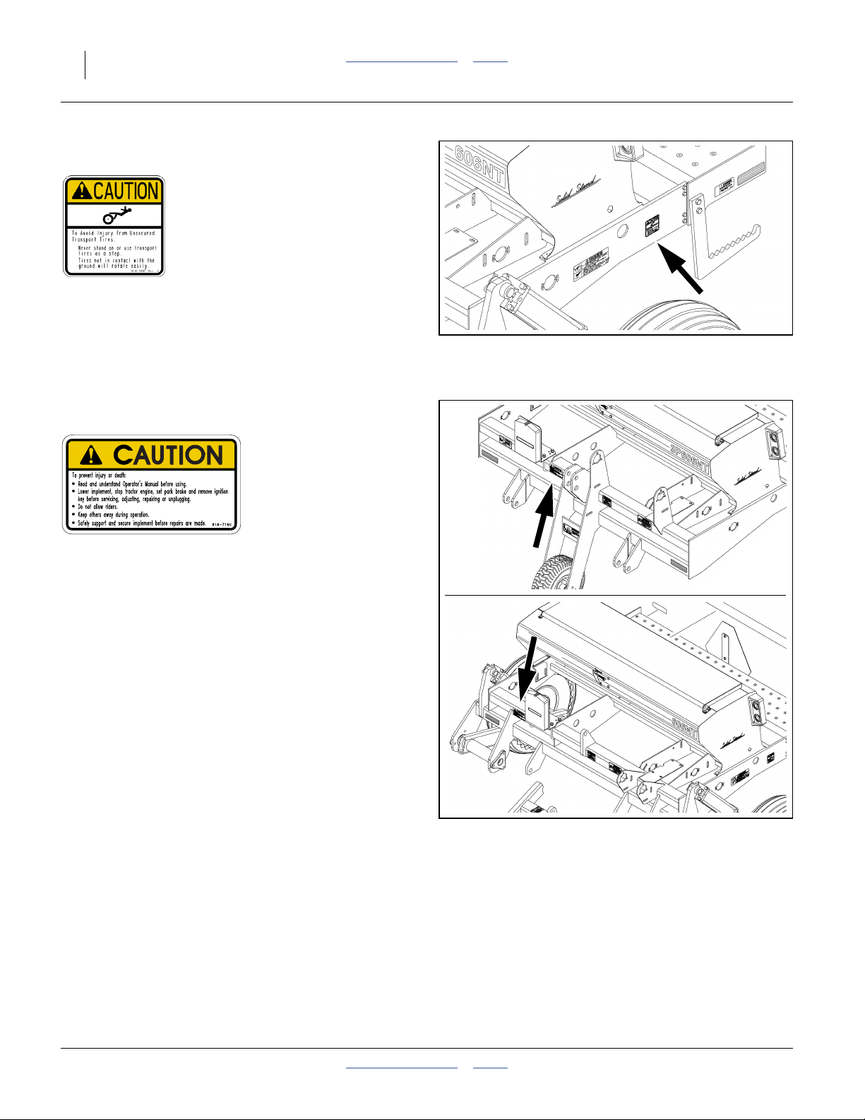
Caution: Tires Not A Step
818-398C
(605NT and 606NT only)
On side frames above tires;
32693
2 total
Tires may be in light contact with ground, or off the
ground, when the drill is lowered.
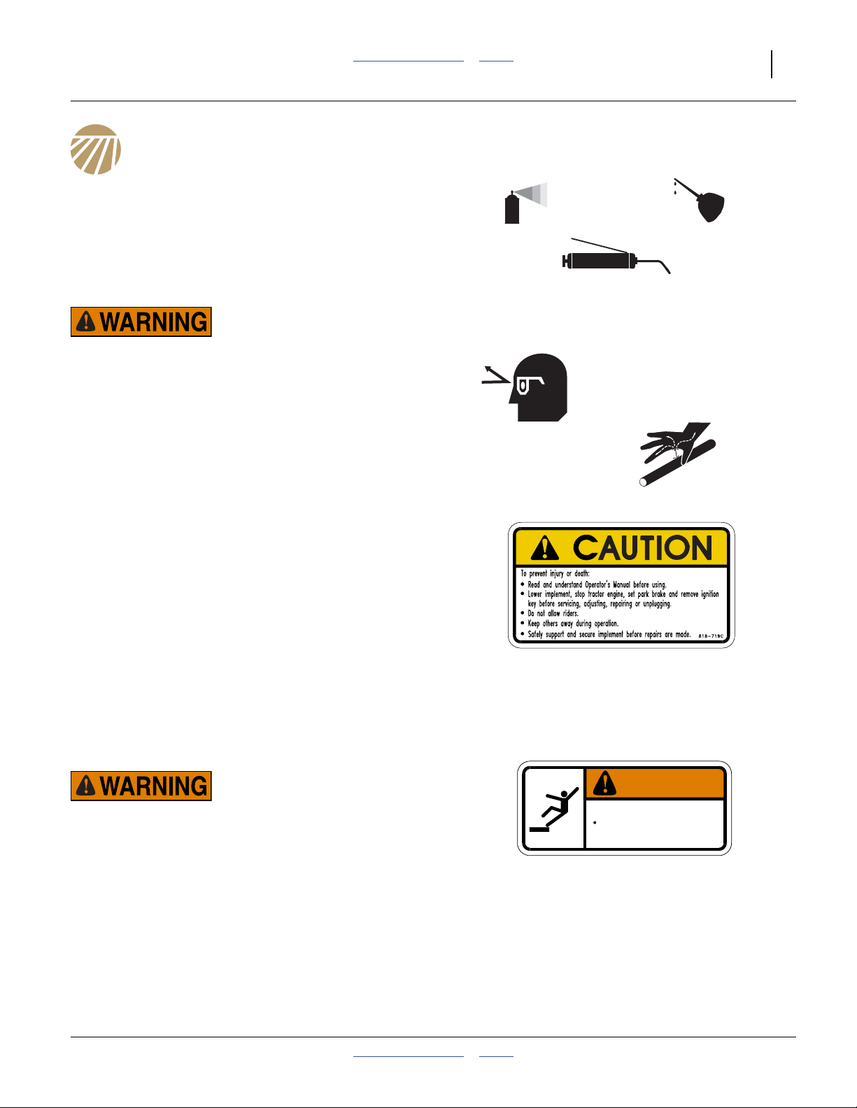
Caution: General
818-719C
3P605NT and 3P606NT:
On front face, upper front frame tube, right of center;
1 total
605NT and 606NT:
On front face, upper front frame tube, right end;
See “Important Safety Information” on page 1.
32695
32693
151-061M Table of Contents Index 2014-02-10
Page 15
Great Plains Manufacturing, Inc. Table of Contents Index Important Safety Information 11
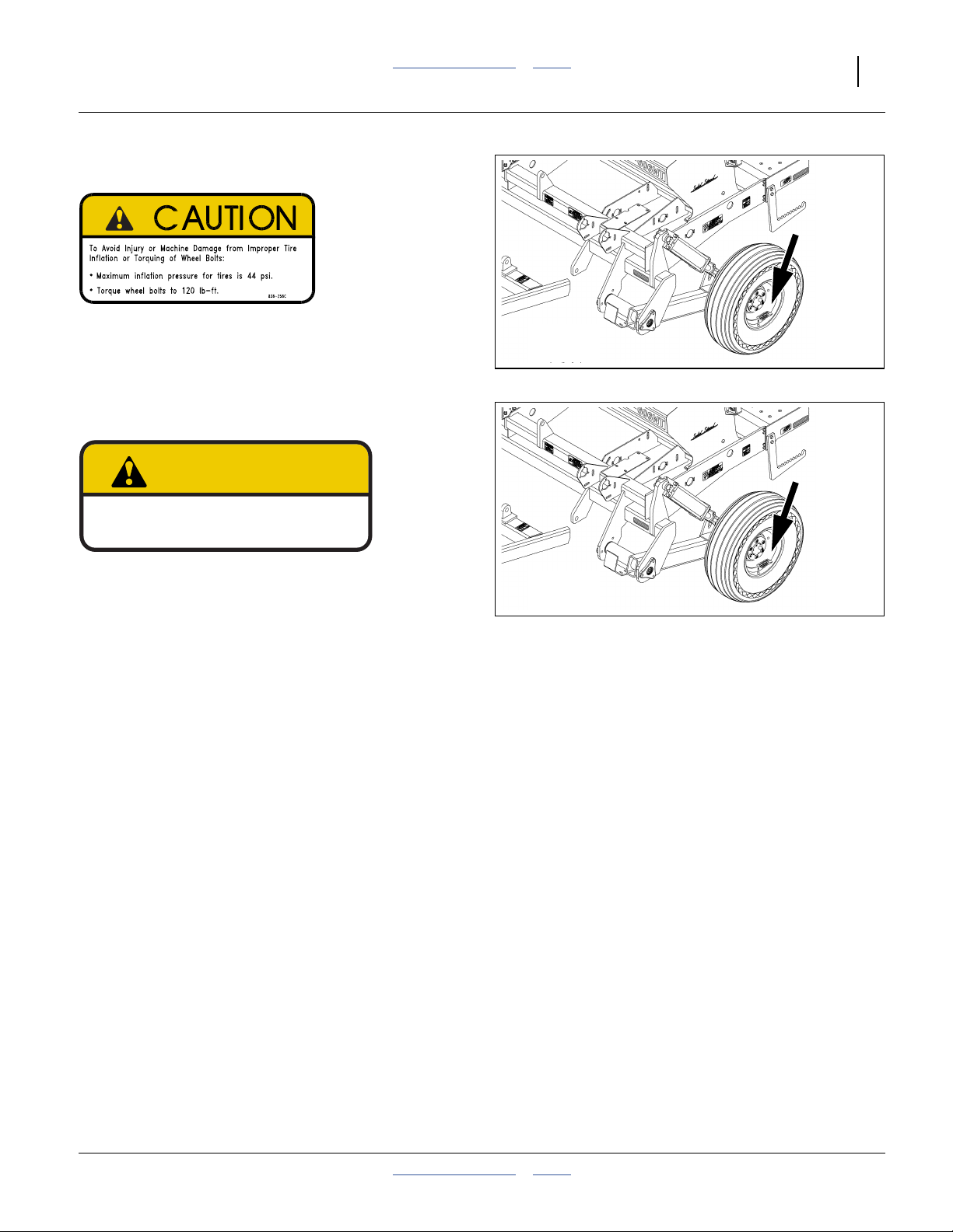
Caution: Tire Pressure and Torque
838-258C
(605NT only, 2006- only)
On rim of each end wheel with 9.5L 8-ply tires;
2 total
Caution: Tire Pressure and Torque
848-021C
CAUTION
To Avoid Injury or Machine Damage from Improper Tire
Inflation or Torquing of Wheel Bolts:
•
Maximum inflation pressure for tires is 60 psi.
•
Torque wheel bolts to 85 lb-ft.
(605NT 2007+, 606NT only)
On rim of each end wheel with 700-15 LT tires;
2 total
848-021C REV. B
32693
32693
2014-02-10 Table of Contents Index 151-061M
Page 16
12 3P605NT, 3P606NT, 605NT & 606NT Table of Contents Index Great Plains Manufacturing, Inc.
Introduction
Great Plains welcomes you to its growing family of new
product owners. Your 6-Foot No-Till Drill has been
designed with care and built by skilled workers using
quality materials. Proper setup, maintenance, and safe
operating practices will help you get years of satisfactory
use from the machine.
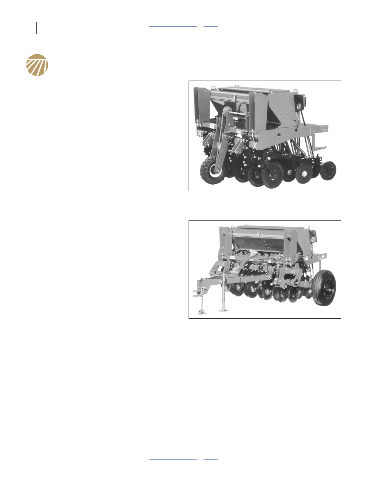
Description of Unit
The 3P605NT and 3P606NT are 3-point seeding
implements. The 605NT and 606NT are towed seeding
implements. This drill has a working width of 7.5 feet
(1.9 m). The drill has straight arm, double disc 05 or
06 Series openers. The opener discs make a seed bed,
and seed tubes mounted between the discs place seed
in the furrow. Press wheels following the opener discs
close the furrow and gauge opener seeding depth.
A T-handle on the opener body makes seeding depth
adjustments.
The metering system is driven from the gauge wheel
(3-point), or from the left end wheel (pull-type). Seeding
rates are set by rate adjustment handles and a Drive
Type gearbox for the main seed box.
Figure 1
3P606NT No-Till Drill
32704
Intended Usage
Use this implement to seed production-agriculture crops
in conventional or minimum tillage applications.
Models Covered
This manual applies to Great Plains drill models:
3P605NT-0975 9-row 7.5-inch (19.1 cm)
3P606NT-0975 9-row 7.5-inch (19.1 cm)
605NT-0975 9-row 7.5-inch (19.1 cm)
606NT-0975 9-row 7.5-inch (19.1 cm)
Standard 3P605NT, 3P606NT, 605NT or 606NT Models
have a main seed box. Native Grass and/or Small Seeds
capability may be added.
Document Family
151-061M Operator Manual (this document)
151-061P 3P606NT, 606NT Parts Manual
151-122B Seed Rate Manual
Figure 2
606NT No-Till Drill
32703
151-061M Table of Contents Index 2014-02-10
Page 17
Great Plains Manufacturing, Inc. Table of Contents Index Introduction 13
Using This Manual
This manual familiarizes you with safety, assembly,
operation, adjustments, troubleshooting, and
maintenance. Read this manual and follow the
recommendations to help ensure safe and efficient
operation.
Right-hand and left-hand as used in
this manual are determined by facing
the direction the machine will travel
while in use unless otherwise stated.
An orientation rose in some line art
illustrations shows the directions of:
Up, Back, Left, Down, Front, Right.
U
R
F
D
B
L
Identifies an Economic (not a Safety) Risk:
NOTICE provides a crucial point of information related to the
current topic. Read and follow the instructions to avoid damage
to equipment and ensure desired field results.
Note: This form sets off useful information related to the
current topic, or forestalls possible
misunderstanding.
The information in this manual is current at printing.
Some parts may change to assure top performance.
Owner Assistance
If you need customer service or repair parts, contact a
Great Plains dealer. They have trained personnel, repair
parts and equipment specially designed for Great Plains
products.
Refer to Figure 3
Your machine’s parts were specially designed and
should only be replaced with Great Plains parts. Always
use the serial and model number when ordering parts
from your Great Plains dealer. The serial-number plate is
located on the upper front frame tube, just left of center.
Record your drill model and serial number here for quick
reference:
Model Number:__________________________
Serial Number: __________________________
Figure 3
Serial Number Location, 606NT
32703
Your Great Plains dealer wants you to be satisfied with
your new machine. If you do not understand any part of
this manual or are not satisfied with the service received,
please take the following actions.
1. Discuss the matter with your dealership service
manager. Make sure they are aware of any problems
so they can assist you.
2. If you are still unsatisfied, seek out the owner or
general manager of the dealership.
2014-02-10 Table of Contents Index 151-061M
For further assistance write to:
Product Support
Great Plains Mfg. Inc., Service Department
PO Box 5060
Salina, KS 67402-5060
gp_web_cs@greatplainsmfg.com
785-823-3276
Page 18
14 3P605NT, 3P606NT, 605NT & 606NT Table of Contents Index Great Plains Manufacturing, Inc.
Preparation and Setup
This section helps you prepare your tractor and drill for
use. Before using the drill in the field, you must hitch the
drill to a suitable tractor and also setup the drill.
Pre-Setup Checklist
1. Verify that dealer pre-delivery is complete (page 67)
and optional accessories are installed (page 68).
2. Read and understand “Important Safety
Information” on page 1.
3. Check that all working parts are moving freely, bolts
are tight, and cotter pins are spread.
4. Check that all grease fittings are in place and
lubricated. See “Lubrication and Scheduled
Maintenance” on page 48.
5. Check that all safety decals and reflectors are
correctly located and legible. Replace if damaged.
See “Safety Decals” on page 6.
6. Inflate tires and tighten wheel bolts as at “Tire
Pressures” on page 60.
Hitching Tractor to Drill
Hitching Model 3P605NT or 3P606NT
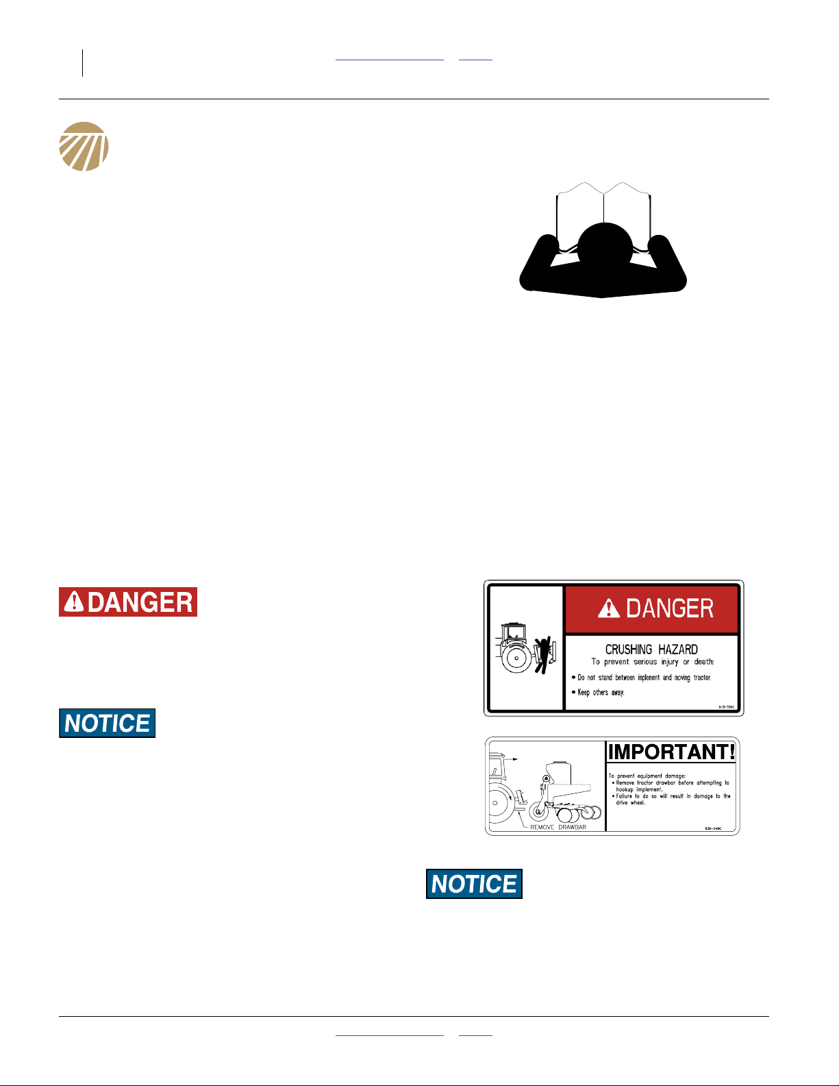
Crushing Hazard:
You may be severely injured or killed by being crushed
between the tractor and drill. Do not stand or place any part of
your body between drill and moving tractor. Stop tractor
engine and set park brake before installing the hitch pin.
Certain Machine Damage:
Remove tractor draw bar before hitching the 3P605NT or
3P606NT. The drill drive wheel will be damaged if drawbar is
not removed.
1. Raise or lower tractor 3-point arms as needed and
pin lower arms to drill.
2. Pin upper arm to drill.
3. Slowly raise drill. Watch for cab interference.
4. Adjust top 3-point link so the top edge of drill box is
parallel with the ground when drilling.
Note: Do not use link to adjust opener depth. For opener
adjustments, refer to “Opener Depth (Press
Wheel Height)” on page 38. Set your tractor
3-point draft control to Float position for planting.
Equipment Damage Risk:
Due to interference with the gauge wheel assembly, drill
models 3P605NT and 3P606NT are not compatible with
Great Plains accessory hitches CPH, PFH and SSH, nor with
the Great Plains hitch set-back kit.
151-061M Table of Contents Index 2014-02-10
Page 19
Great Plains Manufacturing, Inc. Table of Contents Index Preparation and Setup 15
Hitching Model 605NT or 606NT
Crushing Hazard:
You may be severely injured or killed by being crushed
between the tractor and drill. Do not stand or place any part of
your body between drill and moving tractor. Stop tractor
engine and set park brake before installing the hitch pin.
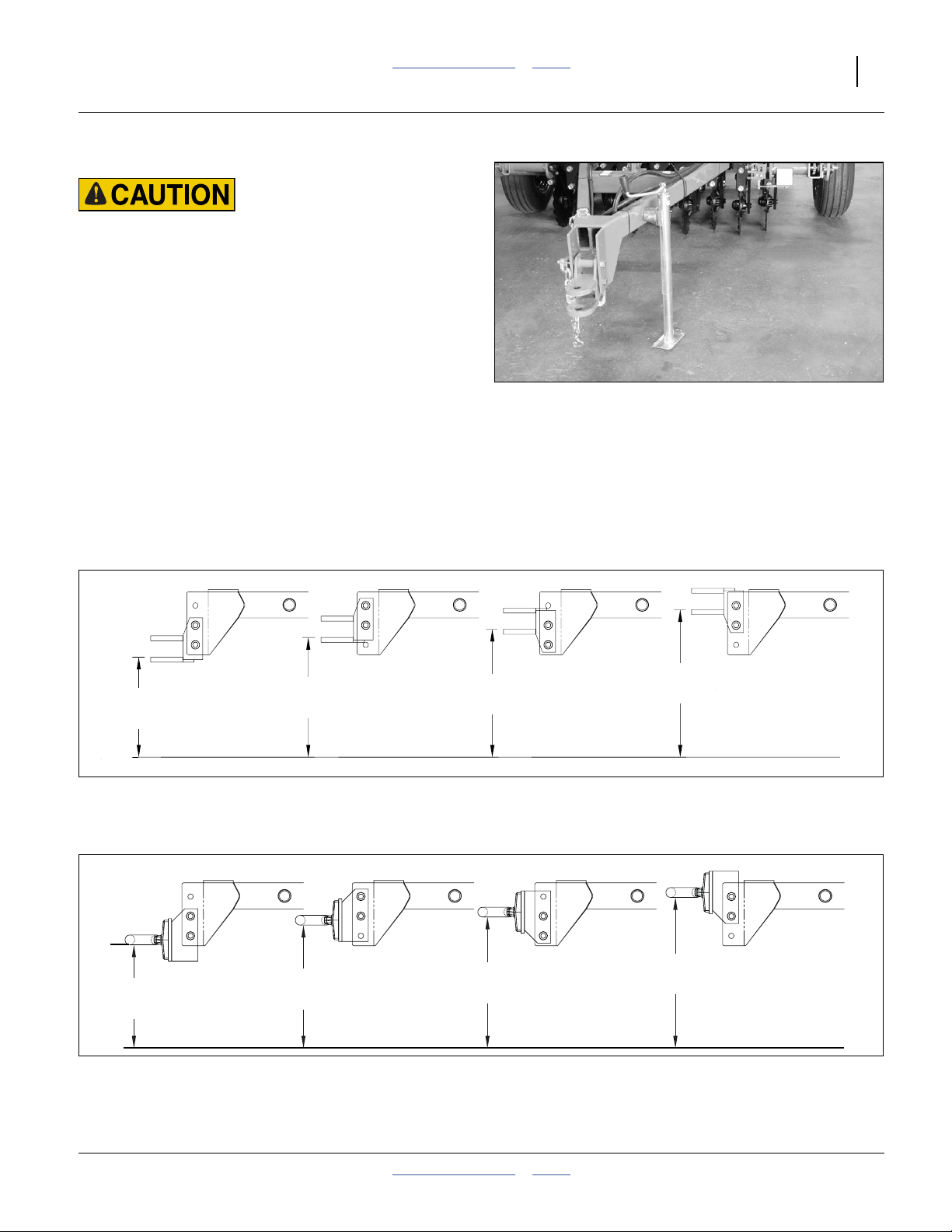
1. With drill lowered in field position and tongue jack
mounted as shown in Figure 4, raise or lower tongue
jack to level drill tongue.
Refer to Figure 5
2. With drill tongue level, adjust drill hitch on drill tongue
to match your tractor-drawbar height. You can move
the hitch up or down or turn it over for a total of four
different hitch heights.
3. When drill hitch matches tractor-drawbar height,
hitch drill to tractor.
4. Securely attach drill safety chain to an anchor on
tractor capable of pulling drill.
Figure 4
Jack in Parking Position
Note: When hitching drill to a different tractor, check for
a difference in drawbar heights. If heights are
different, readjust hitch height accordingly.
18473
159⁄32 in.
38.8 cm
1525⁄32 in.
40.1 cm
189⁄32 in.
46.4 cm
1825⁄32 in.
47.7 cm
1917⁄32 in.
49.6 cm
Figure 5
Clevis Hitch Height Adjustment
201⁄32 in.
50.9 cm
Figure 6
Pintle Hitch Height Adjustment
2217⁄32 in.
57.2 cm
18544
231⁄32 in.
58.5 cm
27216
2014-02-10 Table of Contents Index 151-061M
Page 20
16 3P605NT, 3P606NT, 605NT & 606NT Table of Contents Index Great Plains Manufacturing, Inc.
Hydraulic Hose Hookup (605NT or 606NT)
High Pressure Fluid Hazard:
Shut down tractor before making hydraulic connections. Only
trained personnel should work with system hydraulics.
Escaping fluid under pressure can have sufficient pressure to
penetrate the skin causing serious injury. Use paper or
cardboard, NOT BODY PARTS, to check for leaks. Wear
protective gloves and safety glasses or goggles when working
with hydraulic systems. If an accident occurs, seek immediate
medical assistance from a physician familiar with this type of
injury.
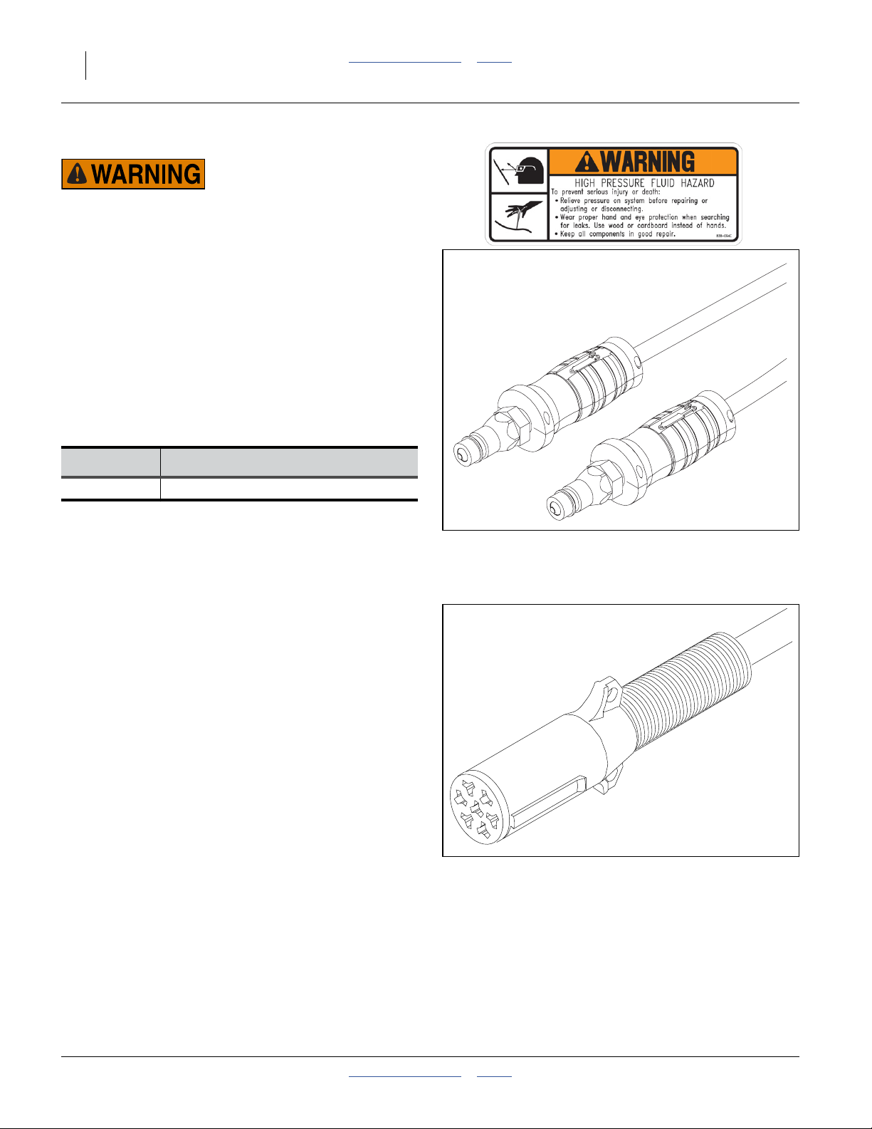
Refer to Figure 7
Hydraulic hoses have directional handles and are color
coded to help you hookup hoses to your tractor outlets.
Hoses that go to the same remote valve pair are marked
with the same color.
Color Hydraulic Function
Blue Transport Lift Cylinders
To distinguish hoses on the same hydraulic circuit, refer
to the symbols on the handles. Hose under
extended-cylinder symbol feeds cylinder base ends.
Hose under retracted-cylinder symbol feeds cylinder rod
ends.
Electrical Connections
Refer to Figure 8
5. Plug drill electrical lead into tractor seven-pin
connector. If your tractor is not equipped with a
seven-pin connector, contact your dealer for
installation.
Figure 7
Hose Handles
Figure 8
Lighting Connector
31733
26467
151-061M Table of Contents Index 2014-02-10
Page 21
Great Plains Manufacturing, Inc. Table of Contents Index Preparation and Setup 17
Height and Leveling the Drill
Height Setup: Model 3P605NT or 3P606NT
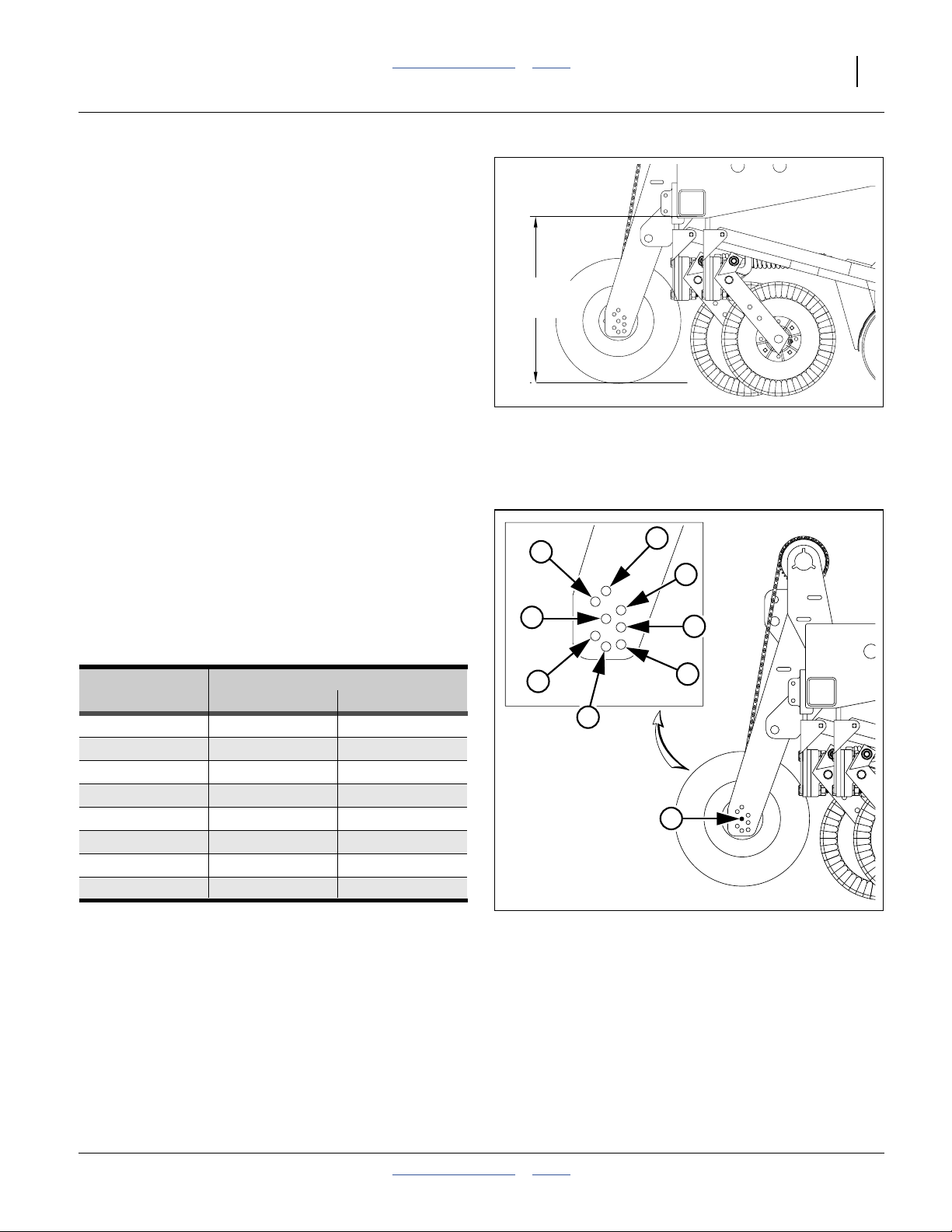
Refer to Figure 9 and Figure 10
1. Initially adjust drill so opener tool bar runs
3
⁄4in. (62.9 cm) above ground when drill is
24
lowered in the field.
2. The drive wheel should be in the fourth mounting
hole from the top (factory setting).
Note: The drive may need to be adjusted due to ground
conditions.
3. Level drill with top 3-point link.
243⁄4 in.
62.9 cm
Adjusting 3-Point Height
Raising the gauge wheel spindle provides deeper coulter
depth. Lowering the wheel provides shallower depth.
Note: Do not lower coulters to aid in penetrating hard soil.
Instead, increase coulter down-force (page 32).
This may require adding optional weight (page 30).
Refer to Figure 10
1. Determine new coulter depth desired. With new
discs, the axle holes provide these depths:
Hole No.
(from top)
1
2
3
4 (f)
5
6
7
8
f. Factory setting.
n. Depth is with new coulter blades.
2. Raise drill, unless wheel is already off ground
sufficiently to allow wheel spindle relocation.
3. Relax chain idlers.
4. Remove wheel bolts. Move spindle to new hole pair.
Re-install wheel bolts.
5. Re-engage chain idlers.
Coulter Depth (n)
Inches mm
3 1/ 2 in. 89 mm
2 7/ 8 in. 73 mm
2 3/ 8 in. 60 mm
1 7/ 8 in. 48 mm
1 3/ 8 in. 35 mm
7/ 8 in. 22 mm
3/ 8 in. 10 mm
1/ 4 in. 6 mm
32774G
Figure 9
Initial Field Height,
3P605NT or 3P606NT
18546
1
2
3
4
6
5
7
8
4
Figure 10
Height Adjustment,
3P605NT or 3P606NT
18509
2014-02-10 Table of Contents Index 151-061M
Page 22
18 3P605NT, 3P606NT, 605NT & 606NT Table of Contents Index Great Plains Manufacturing, Inc.
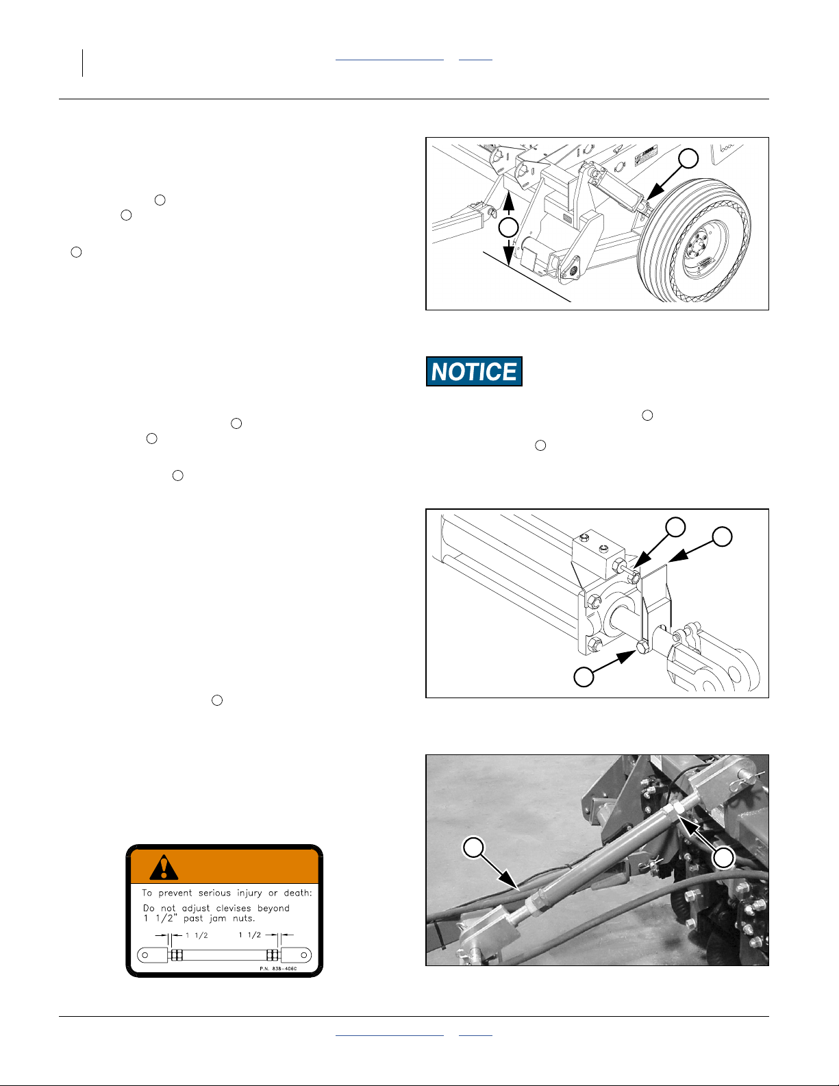
Height Setup: Model 605NT or 606NT
Set Tool Bar Height
Refer to Figure 11 and Figure 12
Tool bar height is controlled by a depth stop
assembly on the left lift cylinder.
The suggested initial tool bar operating height is:
1
243⁄4in. (62.9 cm)
from the base of the opener tool bar to the ground, when
lowered in field conditions (opener discs in ground).
1. Use the tractor remote circuit to raise the drill to the
full extension of both lift cylinders. Hold the drill
raised for several seconds to re-phase the cylinders.
Remove any transport locks.
2. In field conditions, lower the drill to the desired tool
bar height. Pull forward to put openers in ground.
Set the remote to Neutral. Shut off the tractor.
3. Loosen the nut and bolt that secure the stop
weldment to the cylinder rod.
4. Slide the weldment up the rod until it contacts the
valve actuator , then slide it up another
1
⁄8in. (3 mm). Tighten the bolt.
5. Start the tractor. Raise and lower the drill. Pull
forward in ground. The lowering stops when the
weldment moves the actuator a short distance.
Shut off the tractor and verify the tool bar height.
Note: If further adjustment is required, the drill height
changes at approximately half the change in
weldment position. For example, raising the drill
another1⁄8in. (3 mm) would require moving the
weldment up another1⁄4in. (6 mm).
Level Model 605NT or 606NT
Refer to Figure 13
1. Use hitch turnbuckle to level drill.
2. Lower unit to take weight off of drill. Do not adjust
with unit in raised position.
3. Loosen jam nuts on hitch turnbuckle.
4. Turn turnbuckle to shorten or lengthen until top of
drill frame is parallel to the ground being careful not
to extend clevises beyond turnbuckle.
5. Retighten jam nuts on turnbuckle.
1
2
3
4
5
6
1
Figure 11
Pull-Type Tool Bar Height
Field Results Risk:
Prior to first use, check tool bar height or the drill may run
too deep. Model 606NT drills may be shipped with the depth
stop valve actuator set to maximum depth. The actuator
must be adjusted to desired opener height prior to first use.
2
3
Figure 12
Cylinder Depth Stop
6
2
32681
1
5
4
32712
6
WARNING
Figure 13
Pull-Type Turnbuckles
151-061M Table of Contents Index 2014-02-10
18513
Page 23
Great Plains Manufacturing, Inc. Table of Contents Index 19
Operation Instructions
This section covers general operating procedures.
Experience, machine familiarity and the following
information will lead to efficient operation and good
working habits. Always operate farm machinery with
safety in mind.
Pre-Start Checklist
High Pressure Fluid Hazard:
Escaping fluid under pressure can have sufficient pressure to
penetrate the skin. Check all hydraulic lines and fittings before
applying pressure. Fluid escaping from a very small hole can
be almost invisible. Use paper or cardboard, not body parts,
and wear heavy gloves to check for suspected leaks. If an
accident occurs, seek immediate medical assistance from a
physician familiar with this type of injury.
1. Carefully read “Important Safety Information”
starting on page 1.
2. Lubricate drill per “Lubrication and Scheduled
Maintenance” starting on page 48.
3. Check all tires for proper inflation. See “Tire
Pressures” on page 60.
4. Check all bolts, pins and fasteners. See “Torque
Values Chart” on page 61.
5. Check drill for worn or damaged parts. Repair or
replace faulty parts before going to the field.
6. Check hydraulic hoses, fittings and cylinders for
leaks. Repair or replace faulty parts before going to
the field.
7. Rotate both drive wheel to verify that the drive and
meters are working properly and free from foreign
material.
WARNING
Falling Hazard:
Watch your step when walking on drill steps and walkboard.
Falling from drill could cause severe injury or death.
2014-02-10 Table of Contents Index 151-061M
To avoid serious injury or death:
Watch your step when climbing ladder or
walking on walkboard.
838-102C
Page 24
20 3P605NT, 3P606NT, 605NT & 606NT Table of Contents Index Great Plains Manufacturing, Inc.
Transporting 3P605NT or 3P606NT
Transport considerations are different for 3-point and
pull-type models. For pull-type, see page 21.
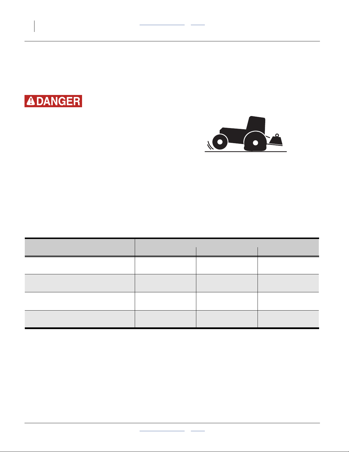
Use an Adequate Tractor (3-Point)
Loss of Control Hazard:
Insufficient weight on tractor steering tires can dangerously
reduce steering authority, particularly during acceleration and
ascending hills. You can lose directional control entirely,
which could result in a major accident, serious injury, or
death. Adding too much ballast could lead to brake or other
mechanical failures, tire failures and loss of control.
▲ Ensure that the tractor is rated for, and correctly ballasted
for the drill’s 3-point loading. Check that drill plus ballast
does not exceed the tractor’s capability.
▲ If the drill has accessory weight brackets, consider moving
any tractor weights present to the tractor during transport.
▲ Avoid transport with material loaded in boxes.
The total drill weight and center of gravity vary
considerably with drill configuration and material load.
See table below.
3P605NT or 3P606NT Example Weights
3-Point Drill Configuration Typical Weights
Boxes Empty Seed Loaded Seed + Weights*
Standard Drill (Main Seed only)
Drill with Native Grass option
Drill with Small Seeds option
Drill with Native Grass & Small Seeds
* 151-058A Weight Kit plus 6 each 100 pound tractor weights, approximately 780 pounds.
* 151-058A Weight Kit plus 6@ 100 pound tractor weights, approximately 780 lbs. 32774C
Continue at “Transport Cautiously” on page 24.
2280 lbs 3000 lbs 3780 lbs
1030 kg 1360 kg 1710 kg
2580 lbs 3300 lbs 4080 lbs
1170 kg 1500 kg 1850 kg
2430 lbs 3150 lbs 3930 lbs
1100 kg 1430 kg 1780 kg
2730 lbs 3450 lbs 4230 lbs
1240 kg 1560 kg 1920 kg
151-061M Table of Contents Index 2014-02-10
Page 25

Great Plains Manufacturing, Inc. Table of Contents Index Operation Instructions 21
Transporting 605NT or 606NT
Transport considerations are different for 3-point and
pull-type models. For 3-point, see page 20.
Use an Adequate Tractor (Pull-Type)
Loss of Control Hazard:
Insufficient tractor weight can dangerously reduce steering
authority, and increase braking loads beyond the capability of
the tractor. You can lose directional control entirely, which
could result in a major accident, serious injury, or death.
2
▲ Ensure that the tractor weighs at least
(including the weight of any Options and materials).
▲ Avoid transport with material loaded in boxes.
The total drill weight varies considerably with drill
configuration and material load. See table below.
⁄3(67%) of the drill
605NT or 606NT Example Weights
Pull-Type Drill Configuration Typical Weights
Boxes Empty Seed Loaded Seed + Weights*
Standard Drill (Main Seed only)
Drill with Native Grass option
Drill with Small Seeds option
Drill with Native Grass & Small Seeds
* 151-058A Weight Kit plus 6 each 100 pound tractor weights, approximately 780 pounds.
* 151-058A Weight Kit plus 6@ 100 pound tractor weights, approximately 780 lbs. 32774D
2700 lbs 3420 lbs 4200 lbs
1220 kg 1550 kg 1910 kg
3000 lbs 3720 lbs 4500 lbs
1360 kg 1690 kg 2040 kg
2850 lbs 3570 lbs 4350 lbs
1290 kg 1620 kg 1970 kg
3100 lbs 3820 lbs 4600 lbs
1410 kg 1730 kg 2090 kg
2014-02-10 Table of Contents Index 151-061M
Page 26

22 3P605NT, 3P606NT, 605NT & 606NT Table of Contents Index Great Plains Manufacturing, Inc.
Use Transport Locks
3
Transport Hazard:
Failure of hydraulic cylinders during transport causes drill to
drop suddenly, which could lead to a serious accident, injury
or death. To prevent an accident, always install cylinder locks
before transporting drill.
Before transporting the drill, check these items:
Cylinder Locks
Refer to Figure 14 or Figure 15, and Figure 16
A cylinder lock is provided for both gauge wheel
hydraulic lift cylinders.
1. Raise drill completely. Set circuit to Neutral.
2. Remove lock channels from storage locations.
3. Place lock channels over rod of cylinder.
4. Install cylinder lock pins and retainer clips .
Note: The cylinder lock can be secured or removed only
after the drill is fully raised.
5. Unload drill box. The drill can be transported with a
full box of grain, but the added weight increases
stopping distance and decreases maneuverability.
Unload drill box before transporting if at all possible.
1
1
2
3 4
Figure 14: 2012+
Lift Cylinder Lock Storage
1
3
1
4
36177
4
3
Figure 15: 2011-
Lift Cylinder Lock Storage
19653
4
3
1
2
Figure 16
Lift Cylinder Lock (RH)
151-061M Table of Contents Index 2014-02-10
3
27217
Page 27

Great Plains Manufacturing, Inc. Table of Contents Index Operation Instructions 23
Disengage Lock-Out Hub
Refer to Figure 17 and Figure 18
6. At lock-out on left hub, pull pin away from wheel
and rest in outer shallow detents .This disengages
5
6
the hub from the drive train and prevents excessive
wear of drive system during transport.
5
6
Figure 17
Lock-Out Hub Engaged
5
Figure 18
Lock-Out Hub Disengaged
18480
27218
2014-02-10 Table of Contents Index 151-061M
Page 28

24 3P605NT, 3P606NT, 605NT & 606NT Table of Contents Index Great Plains Manufacturing, Inc.
Transport Cautiously
Keep Clearance in Mind
Remember that the drill may be wider than the tractor.
Allow safe clearance.
Observe Road Rules
Comply with all national, regional and local safety laws
when traveling on public roads.
Reduce speed on rough roads.
Loss of Control Hazard:
Towing at high speeds or with a vehicle that is not heavy
enough could lead to loss of vehicle control. Loss of vehicle
control could lead to serious road accidents, injury and death.
To reduce the hazard, do not exceed 20 mph (30 kph).
Loading Seed
Possible Chemical Hazard:
Take all prescribed material safety precautions.
Fully loaded with dense seed, the drill weighs an
additional 1155 lbs (529 kg). Include this weight when
checking tractor capability.
The drill must be hitched for seed loading.
Load slightly more material than needed, because
consumption rates can vary between compartments
even though the furrow rates are identical.
1 2
Main Seed Box Loading
1. Check that all meter doors are positioned for the
seed size, and not set for clean-out. See “Position
Seed Cup Doors” in seed Rate Manual. If loading
prior to transport, set them to position 1 (smallest
seed).
2. Install or remove optional seed plugs as desired for
the row spacing planned. Refer to Seed Rate
Manual.
If loading prior to transport, and calibration has not yet
been done, set Seed Rate Handle to 0. At 0, and with the
doors at 1, no seed can leak during transport.
3. The main seed box lid handle is also a latch. It needs
to pivot up to release the lid.
4. Load seed evenly into compartments.
To reduce wear on unused boxes that may also be
present:
• Remove final drive chain for Small Seed box.
• Remove any Native Grass chain.
23
Figure 19
Native Grass Box Open
1
28362
Loading Native Grass Box
1. The main seed box lid handle is also a latch. It needs
to pivot up to release the lid.
2. Load seed evenly into compartments.
3. Add1⁄3cup (80 mL) graphite seed lubricant on top of
the loaded seed. In humid conditions, double or triple
this amount as needed.
3
Loading Small Seeds Box
1. If loading prior to transport, and calibration has not
yet been done, set Seed Rate Handle to 0. At 0, no
seed can leak during transport.
2. Take all necessary materials safety precautions if the
seed is treated.
3. The Small Seeds lid is held closed by two external
rubber latches. Pull them up and to the rear to
release the lid.
4. Load seed evenly into compartments.
5. To reduce wear, remove main shaft drive chains for
main seed boxes.
151-061M Table of Contents Index 2014-02-10
Page 29

Great Plains Manufacturing, Inc. Table of Contents Index Operation Instructions 25
Field Operation
1. Hitch drill to a suitable tractor (page 14).
For model 3P605NT or 3P606NT, continue at step 5.
2. Raise drill. Hold at raised for several seconds to
re-phase lift cylinders. Set circuit to Neutral. Shut off
tractor.
Refer to Figure 16 page 22 and Figure 15 on page 22
3. Remove transport lock channels from cylinder rods.
Move them to storage and re-pin. See page 22.
Refer to Figure 20
4. Engage drive with lock-out hub on the left gauge
wheel. Pull pin away from hub. Rotate 90°.
Release into deeper notch pair.
Note: Pin may not seat fully immediately, but will at next
drill movement.
5. Set seed population per rate chart and calibration,
from Seed Rate manual.
6. Load box with clean seed.
7. Raise drill. Using calibration crankaor 3-point gauge
gauge wheel, operate the meter drive system. Check
that feed cups, seed tubes and drives are working
properly and free from foreign material by looking for
seed flow under each opener.
8. Lower drill. With a 3-point model, set hitch to Float.
9. Pull forward. Stop. Check tool bar height and opener
depth.
10. Begin seeding.
11. Always lift drill out of the ground when turning at row
ends and for other short-radius turns. Seeding stops
automatically as drill is raised.
5
5
Figure 20
Lock-Out Hub Engaged
Machine Damage Risk:
Never back up with openers in the ground. Seed tube and
firmer damage is likely. Seed tube plugging is almost certain.
Always raise the drill when stopped and prior to reversing.
18480
Re-Phasing Cylinders
The lift cylinders may, after a period of time, get out of
time or phase. The effects of this can be seen when one
side of the drill is running too low or too high because its
lift cylinder is either over extended or not retracted
compared to the other lift cylinder.
To re-phase the cylinders, raise drill completely and hold
tractor hydraulic lever on for a few seconds to give
cylinders time to re-phase.
Each time drill is raised out of ground momentarily
reverse hydraulic lever immediately after re-phasing to
allow cylinders to retract about1⁄2in. (2.5 cm). This helps
maintain a level drill.
Note: Having cylinders become gradually out of time is
different than having air trapped in the system, a
problem remedied by bleeding (page 46).
a. A calibration crank kit (page 53) is available for drills manufactured prior to 2005-10-01.
2014-02-10 Table of Contents Index 151-061M
To Tractor
Figure 21
605NT or 606NT Lift Hydraulics
18676
Page 30

26 3P605NT, 3P606NT, 605NT & 606NT Table of Contents Index Great Plains Manufacturing, Inc.
Acremeter Operation
An electronic acremeter is standard on Models 3P606NT
and 606NT. It is available as an accessory for Models
3P605NT and 605NT. You may have any of three
different meter styles.
The acremeter counts shaft rotations whenever the shaft
is rotating - this is with the drill lowered and in motion or
during crank operation. The meter is programmed to
display rotations as acres or hectares, when using all
rows, factory-specified tires and tire inflations.
Note: Unusual conditions and/or non-standard row
spacings can cause the acremeter tally to vary
from actual acres planted.
DataTrac Electronic Acremeter
Refer to Figure 22
If you have the circular end-of-shaft acremeter depicted
in Figure 22, see Electronic Acremeter Manual
152-325M.
Great Plains Acre Counter
Refer to Figure 23
If you have the rectangular meter, mounted on the front
face of a tool bar, depicted in Figure 23, see Electronic
Acremeter Manual 194-074M.
2013- Great Plains Electronic Acremeter
Refer to Figure 24
If you have the circular end-of-shaft acremeter depicted
in Figure 24, see Electronic Acremeter Manual
152-314M.
Figure 22
DataTrac Acremeter
Figure 23
GP Acre Counter
34937
34775
Figure 24
2013- Electronic Acremeter
151-061M Table of Contents Index 2014-02-10
27378
Page 31

Great Plains Manufacturing, Inc. Table of Contents Index Operation Instructions 27
Parking
Perform the following steps when parking the drill for 36
hours or less. Refer to “Storage”, to prepare for
long-term storage.
Parking Model 3P605NT or 3P606NT
1. Park drill on a level, solid area.
2. Lower 3-point hitch until drill is on the ground.
3. Unplug wiring harness from tractor. Do not allow
harness end to rest on the ground.
4. Extend or retract the top link of the tractor until top 3point pin is free. Remove pin.
5. Remove pins from lower links.
Parking Model 605NT or 606NT
1. Park drill on a level, solid area.
2. Lower drill until openers are resting on the ground.
3. Securely block tires to prevent rolling.
Refer to Figure 25 and Figure 26
4. Move jack to side stob near hitch. On older drills,
rotate jack 90 degrees from storage position to
usage position. Re-pin as shown in Figure 26. If
ground is soft, place a board or plate under jack.
Note: On drills manufactured after August 1, 2006, a
storage jack stob is located on top of the tongue.
5. Extend jack until tongue weight is off tractor drawbar.
Refer to Figure 27
(which depicts the hitch of a pull-type drill; the hose caddy
and connector storage cap are similar on 3-point drills, if they
have hydraulics)
6. Set tractor remote circuit for Lift to Float. Unplug
hydraulic hoses. On newer drills, store the hose
1 2
ends in the keyhole slots of the hose caddy
plate.
7. Unplug wiring harness from tractor. On newer drills,
insert the lighting connector into the bottom of the
connector cap . Rotate the plug as necessary until
the keying tab clears a mating cutout in the cap
base, then rotate the plug 90°. Do not allow hose
ends or cable ends to rest on the ground.
8. Remove hitch bolt and safety chain from tractor
drawbar.
4
5
3
Figure 25
Parking Jack Storage
Figure 26
Parking Jack Lowered
4
5
3
2
24481
18473
1
Figure 27
Hose and Connector Storage
2014-02-10 Table of Contents Index 151-061M
36173
Page 32

28 3P605NT, 3P606NT, 605NT & 606NT Table of Contents Index Great Plains Manufacturing, Inc.
Storage
Store drill where children do not play. If possible, store
the drill inside for longer life.
1. Unload seed boxes. Thoroughly clean
seed-treatment residue from boxes and feed cups.
See “Seed Clean-Out” on page 43.
2. Remove any dirt and debris that can hold moisture
and cause corrosion.
3. Lubricate and adjust all roller chains.
4. Take special care to oil feed cup drive sprocket in its
square bore.
5. Perform “Lubrication and Scheduled
Maintenance” starting on page 48.
6. 605NT or 606NT: Grease exposed cylinder rods.
7. Inspect drill for worn or damaged parts. Make repairs
and service during the off season.
8. Use spray paint to cover scratches, chips and worn
areas on the drill to protect the metal.
9. Disconnect seed hoses from openers. Permanent
elongation and premature cracking of hoses may
occur if stored connected. Plug hose ends to prevent
pest entry into seed boxes.
10. Cover with a tarp if stored outside.
151-061M Table of Contents Index 2014-02-10
Page 33

Great Plains Manufacturing, Inc. Table of Contents Index 29
Adjustments
To get full performance from your drill, you need an
understanding of all component operations, and many
provide adjustments for optimal field results. Some of
these have been covered earlier in this manual.
Even if your planting conditions rarely change, some
items need periodic adjustment due to normal wear.
Planting Depth
Setting nominal planting depth, and achieving it
consistently, is affected by multiple adjustable drill
functions. From greatest to least effect they are:
• Opener depth (press wheel height)
• Coulter depth
• Opener down-pressure (spring)
• Opener frame down-force (optional weights)
• Row unit down-pressure spring
• Opener (tool bar) height
• Disc blade adjustments (as discs wear)
Seed Rates
Seeds are applied by fluted feed meters driven by the left
end or center gauge wheel. Independent mechanisms
control the rate for each box. Changing one rate does not
affect the rate of other boxes.
Rate setting details are in Seed Rate manual 151-122B.
Main Box seed rate is controlled by adjustments for:
• Drive Type gearbox lever
• Rate handle at seed box (drill front)
• Feed Cup Door handle (one each seed tube)
Native Grass (Option) Seed rate is controlled by:
• Sprocket pairings at drill front
• Rate Reduction kit (if used)
Small Seeds (Option) rate is controlled by a Rate
Handle (drill rear).
Adjustment Page The Adjustment Affects
Main Seed Box Rate
Drive Type SRM
Rate Adjustment Handle SRMaFine seed rate
Seed Cup Doors SRMaConsistent seed metering
Native Grass Rate
Sprocket Selection SRMaFine seed rate
Seed Rate Reduction SRMaCoarse seed rate
Small Seeds Rate SRMaFine seed rate
Frame Height 17 Compensate for unusual opener depths
Frame Level 17 Consistent seed depth
Frame Weight Adjustment 30 Consistent seed depths in challenging conditions
Coulter Depth 31 Furrow depth and consistent seed depth
Coulter Down-Force 32 Consistent furrow in challenging conditions
Drive Clutch Adjustment 32 Seeding only with openers in ground
05/06 Series Row Unit Adjustments 33
Opener Spring 34 Consistent seed depths in challenging conditions
Disc Blade Adjustments 35 Compensate for disc wear
Disc Scraper Adjustment 43 Consistent seeding depth
Opener Depth (Press Wheel Height) 38 Primary control of seed depth
Press Wheel Selection 57 Furrow coverage behind seeding
Drive Idler Adjustment (605NT or 606NT) 43 Consistent seed flow
a. SRM: Seed Rate Manual: This adjustment is described in manual 151-122B.
a
Coarse seed rate
2014-02-10 Table of Contents Index 151-061M
Page 34

30 3P605NT, 3P606NT, 605NT & 606NT Table of Contents Index Great Plains Manufacturing, Inc.
Frame Weight Adjustment
In some challenging no-till conditions, the drill may not
have enough weight to enable consistent coulter soil
penetration. In such cases, additional weight may help.
An optional weight bracket kit is available. See page 59
for ordering information. The kit includes two brackets .
1
The kit itself adds 180 pounds (82 kg) to the drill. It
accepts up to 600 pounds (272 kg) of standard tractor
weights (300 pounds on each bracket), for a maximum of
780 pounds (354 kg) additional weight.
See table at right for available down-force per coulter,
with various drill and weight kit configurations.
1
Possible Transport Hazard:
Re-check that the tractor or towing vehicle is adequate for
transport, particularly with a 3-point drill. Consider
transporting without weights on the drill. A weight kit with
maximum weights can increase empty drill weight by 34%.
Tractor Damage / Field Results Risks:
With weights installed, re-check that the tractor is adequate to
pull the drill afield. A tractor that was marginal with the
standard drill may provide inadequate performance with
accessory weights.
Always install equal weight on each bracket. Unbalanced
weights causes uneven furrow and seeding depth across the
drill.
Note: The maximum number of tractor weights may vary
by weight style and supplier.
After installing weights, re-check frame height and level
(page 17), coulter depth (page 31) and opener disc
depth (page 38).
Figure 28
32703
Accessory Weight Brackets
Maximum Per Coulter
Drill Configuration 3P605NT 605NT
(no seed loaded)
3P606NT 606NT
Standard Drill 253 lbs 294 lbs
(no weight kit)
115 kg 133 kg
Standard Drill 287 lbs 328 lbs
Kit, plus 300 Pounds
130 kg 149 kg
Standard Drill 320 lbs 361 lbs
Kit, plus 600 Pounds
145 kg 164 kg
Drill w/ Small Seeds (SGS) 337 lbs 378 lbs
Kit, plus 600 Pounds
153 kg 171 kg
Drill w/ Native Grass (NG) 353 lbs 394 lbs
Kit, plus 600 Pounds
160 kg 179 kg
Drill with NG & SGS 370 lbs 405 lbs
Kit, plus 600 Pounds
168 kg 184 kg
32774E
151-061M Table of Contents Index 2014-02-10
Page 35

Great Plains Manufacturing, Inc. Table of Contents Index Adjustments 31
C
Coulter Adjustments
Refer to Figure 29
A no-till coulter , is mounted directly ahead of each
opener on the drill. The coulters cut through heavy trash
and make a groove in the soil for the openers.
The coulter is designed to operate with its spring at full
extension. The spring is briefly compressed as the disc
encounters and rides over difficult obstructions.
Coulter Depth
Great Plains recommends operating at a tool bar height
3
⁄4in. (62.9 cm). Small adjustments may be
of 24
required for unusual seeding depths and as coulter discs
wear. If the coulters are not reaching desired depth (and
the springs are uncompressed), the drill may need more
weight (page 30).
Drill-wide coulter depth is controlled by tool bar height.
The coulters are mounted on the drill frame. Group
coulter cutting depth changes as the drill height is raised
and lowered.
Note: When the opener frames are running level, the
opener disc depth is
depth.
Tool bar height is set by the tractor hitch for 3-point drills,
and by cylinder depth stop (page 18) for pull-type drills.
Individual Coulter Depth
Refer to Figure 29 and Figure 30
Individual coulter depth may be adjusted by raising and
lowering the spring bar .
1. Determine the new coulter depth desired, and/or the
difference between that and the current depth.
2. Raise the drill until the coulter discs are just touching
the ground. The press wheels are supporting some
row unit weight at this point.
3. Measure the current spring bar length , from
bottom of tool bar to bottom of spring bar. For
reference, the factory setting is:
5
121⁄2±1⁄8in. (31.8±3 mm)
Determine the new bar length required.
4. Loosen the clamp bolts . Use a mallet to adjust the
bar height. Re-tighten the clamp bolts to Grade 5
torque specification.
1
3
2
2
4
1
18645
1
⁄4in. (6 mm) above coulter
3
5
Figure 29
Frame-Mounted Coulter
Seeding Depth Risk:
When adjusting coulter height, also reset opener spring force
(page 34). Changing the coulter height changes the distance
between row unit and spring attachment.
3
6
6
5
TO 9
Figure 30
32612
Coulter Spring Bar
2014-02-10 Table of Contents Index 151-061M
Page 36

32 3P605NT, 3P606NT, 605NT & 606NT Table of Contents Index Great Plains Manufacturing, Inc.
Coulter Down-Force
Refer to Figure 31
Coulter springs are preset at:
10 in. (25.4 cm)
giving coulters an initial maximum operating force of
400 pounds (181 kg). This setting is adequate for many
difficult no-till conditions.
2
10.0 inches
25.4 cm
Machine Damage Risk:
Resetting coulter-spring length shorter than 93⁄4in. (24.8 cm)
inches may contribute to a premature failure of parts not
covered by warranty. If additional force is needed, add weights
to drill (page 30).
For lighter no-till conditions where rocks or other
obstructions are a problem, you can lengthen coulter
springs to protect coulters from impact. Refer to table at
right.
1. Measure current spring length.
2. Loosen or remove jam nut .
3. Rotate adjust nut to set spring length.
4. Tighten set jam nut.
8
7
Drive Clutch Adjustment
(Models 606NT and 605NT only)
Refer to Figure 32
The main drive clutch on a pull-type drill is a
mechanical-release, jaw-style design. You may need to
adjust the clutch for proper engagement and
disengagement.
When properly adjusted, the cam plates disengage the
clutch jaws completely when the drill is raised. When
lowered in field position, clutch jaws should be engaged.
To adjust, loosen bolts on clutch tab . Slide tab up or
down to change point at which cam plates meet. When
satisfied with adjustment, retighten bolts on clutch tab.
1
2 3
2
Spring Length
Inches mm
10 1/ 2 in.
10 1/ 4 in.
(f) 10 in.
9 3/ 4 in.
f. Factory setting.
1
8
Figure 31
Coulter Spring Length
Initial Vertical
Coulter Force
Pounds Kilograms
267 mm
260 mm
254 mm
248 mm
175 lbs. 79 kg
300 lbs. 136 kg
400 lbs. 181 kg
525 lbs. 238 kg
2
7
13990
32774J
3
Figure 32
Drive Clutch
151-061M Table of Contents Index 2014-02-10
18482
Page 37

Great Plains Manufacturing, Inc. Table of Contents Index Adjustments 33
05/06 Series Row Unit Adjustments
Refer to Figure 31 (which depicts an 06 Series row unit
populated with most optional accessories)
From front to back, an 05/06 Series row unit (opener)
can include the following capabilities (some optional):
1. Coulter (standard)
This is not part of the opener, but is co-mounted with
it on the tool bar. See “Coulter Adjustments” on
page 31.
2. Opener Discs (standard)
Row-unit double disc openers create the seedbed
furrow. They have adjustments for spacing. See
“Disc Blade Adjustments” on page 35.
3. Main Seed Hose (standard)
Seed released by the metering cups is gravity fed by
the hose to the seed tube (not shown) between the
opener discs. The hose and seed tube require no
adjustments.
4. Down-Pressure Springs (standard)
Two springs per row provide the primary force on the
opener discs. The spring setting may need
adjustment for challenging soil conditions and/or for
changes in coulter depth. See “Opener Spring” on
page 34
5. Inside Scraper (standard)
This feature helps prevent soil buildup on the inside
surfaces of the opener discs, allowing them to meet
sharply and prepare a crisp seed furrow. See “Disc
Scraper Adjustment” on page 36.
6. Seed Firmer (seed flap standard)
A seed firmer confines seed bounce and can press
the seed into the furrow. The standard seed flap
requires
Replacement” on page 45. Optional Keeton® or
Seed-Lok®firmers do have adjustments. See “Seed
Firmer Adjustments” on page 37.
7. Option Seed Hose(s) (optional)
If Native Grass or Small Seeds options are installed,
there will be one or two additional seed hoses at or
aft of the springs. The Small Seeds tube may be
reversed if desired. See “Seed Firmer
Adjustments” on page 37.
8. Press Wheel Height (standard)
The T-handle is primary control for seeding depth.
See “Opener Depth (Press Wheel Height)” on
page 38. The press wheels have no other
adjustments, but a choice of press wheel styles and
sizes is available. Consult your dealer.
a
no adjustments. See “Seed Flap
1
Machine Damage Risk:
Never back up with row units on or in the ground. Seed tubes
will plug or be seriously damaged. Raise the drill for all
reverse and short radius turns, and when stopping while facing
up hill.
3
4
2
6
Figure 33
06 Series Row Unit
7
8
5
32720
a. The seed flap may need to be shortened in length if an optional Keeton® or Seed-Lok® firmer is installed.
2014-02-10 Table of Contents Index 151-061M
Page 38

34 3P605NT, 3P606NT, 605NT & 606NT Table of Contents Index Great Plains Manufacturing, Inc.
Opener Spring
Opener springs provide the down pressure necessary for
opener discs to open a seed trench. The springs allow
the openers to float down into depressions and up over
obstructions.
Each opener spring can be adjusted for down pressure.
This is useful when planting in tractor tire tracks.
If coulter depth is altered for a row, the spring
pre-compression needs to be changed to compensate
for the change in row unit operating height.
Refer to Figure 34 and Figure 35
To adjust the pressure, remove “W” clip at bottom of
spring. Place “W” clip in a higher hole in spring rod for
more pressure or in a lower hole for less pressure.
Use this adjustment only for a few rows, typically in tire
tracks.
Do not set row force higher on all rows. Instead use
coulter adjustments (page 31) and frame weight
adjustments (page 30).
Re-check drill level (page 17) after adjusting row force.
“W”
Figure 34
Minimum Force
12102
“W”
Figure 35
Maximum Force
12103
151-061M Table of Contents Index 2014-02-10
Page 39

Great Plains Manufacturing, Inc. Table of Contents Index Adjustments 35
Disc Blade Adjustments
Raise drill and block it up or lock it up.
Opener Disc Spacing
Sharp Object Hazard:
Be careful working around and handling disc blades. Wear
gloves. Edges of both new and well-worn blades can be sharp.
Opener disc angle and stagger is not adjustable, but
disc-to-disc spacing is, and may need attention as discs
experience normal wear. Spacers must be reset when
blades are replaced.
Refer to Figure 36
The ideal spacing causes the blades to be in contact for
about one inch. If you insert two pieces of paper between
the blades, the gap between them should be
0 to 1.75 in. (0 to 4.4 cm)
If the blades do not touch, they should at least be close
enough so that a business card encounters some friction
when passing between them.
If the contact region is significantly larger or the gap too
wide, it needs to be adjusted by moving one or more
spacer washers. If the contact region varies with blade
rotation, one or both blades is likely bent and in need of
replacement. If removing all spacers cannot bring the
blades into contact, they are worn out and need
replacing.
Adjusting Disc Contact
Refer to Figure 37
1. Remove the bolt retaining the opener disc on one
1
side. Carefully remove the disc, noting how many
spacers are outside the disc and inside the disc.
Do not lose the hub components and dust cap .
2
3
Note: It is not necessary to remove the hub flange or
bearing for this adjustment.
2. To reduce the spacing between the discs (the normal
case), move one spacer washer from the inside to
1
the outside of the disc. It may be necessary to
loosen the scraper (page 36) to reduce disc-to-disc
spacing.
3. Re-assemble and check disc contact.
4. Re-adjust scraper.
Figure 36
Checking Disc Contact
3
1
2
2
Figure 37
Adjusting Disc Spacers
26451
26385
2014-02-10 Table of Contents Index 151-061M
Page 40

36 3P605NT, 3P606NT, 605NT & 606NT Table of Contents Index Great Plains Manufacturing, Inc.
Disc Scraper Adjustment
To keep opener discs turning freely, dirt scrapers are
mounted between discs to clean as the discs rotate. As
field conditions vary, scrapers may need to be adjusted.
In damp conditions, scrapers may need to be lowered. If
openers are not turning freely, scrapers may need to be
raised.
Re-adjust scrapers when replacing discs or adjusting
disc spacing.
Refer to Figure 38
To adjust scrapers, loosen3⁄8inch bolt shown in and
4
move scraper as needed.
4
Figure 38
Disc Scraper Adjustment
18647
151-061M Table of Contents Index 2014-02-10
Page 41

Great Plains Manufacturing, Inc. Table of Contents Index Adjustments 37
Seed Firmer Adjustments
Standard 05/06 Series row units include a seed flap.
An optional Seed-Lok
ordered separately.
The seed flap requires no adjustment, but may need to
be replaced if worn, and may need to be shortened if an
optional seed firmer is added after initial delivery. See
also “Seed Flap Replacement” on page 45.
Sharp Object Hazard:
Use caution when making adjustments in this area. Row unit
disc blades may be sharp. To adjust the Keeton
lower the drill until the discs of the row units are resting on the
ground.
Seed-Lok® Lock-Up (Option)
Optional Seed-Lok® firming wheels provide additional
seed-to-soil contact. The wheels are spring loaded and
do not require adjusting. In some wet and sticky
conditions the wheels may accumulate soil. To avoid
problems associated with this, you can lock-up the
firmers.
Refer to Figure 39 (shown with an opener disc removed for
clarity - this task can be performed with discs mounted)
To lock up Seed-Lok® wheels:
1. Pull catch wire aside.
2. Pull firming-wheel arm up and release wire to
catch arm.
®
or Keeton® seed firmer may be
®
Seed Firmer,
5
6
Figure 39
Seed-Lok® Lock-Up
5
6
27122
Keeton® Seed Firmer Adjustment (Option)
The optional Keeton® Seed Firmer is an engineered
polymer shape that slides down the seed trench. It traps
seeds as they exit the seed tube and firms them into the
bottom of the furrow “V”.
Refer to Figure 40
The Firmer is provided with a preset tension which is
recommended for using the first year. The tension
screw can be tightened in subsequent years according
1
to your needs. Firmers should provide just enough
tension to push seeds to the bottom of the trench.
1
Figure 40
Keeton® Seed Firmer
2014-02-10 Table of Contents Index 151-061M
26390
Page 42

38 3P605NT, 3P606NT, 605NT & 606NT Table of Contents Index Great Plains Manufacturing, Inc.
Small Seeds Tube Adjustment (Option)
Refer to Figure 41
On a drill with the Small Seeds option, deeper seed
placement may be achieved by rotating the seed tube
to face forward.
This orientation is suggested only if the seed firmer is a
seed flap. If a Keeton
falls on the firmer and may be scattered rather than
placed deeper.
®
or Seed-Lok® is present, seed
1
1
Opener Depth (Press Wheel Height)
A press wheel attached to each opener body controls
seeding depth . To maintain consistent depth, the
relationship between the bottom of the opener discs and
press wheel is fixed upwardly by an adjustable stop on
each opener.
The press wheels also close the seed trench and gently
press soil over seed. To provide consistent soil firming,
press wheels are free to move down from normal
operating position. This maintains pressing action even if
opener discs encounter obstructions or hard soil.
To adjust, first raise openers slightly, then lift and slide
T handles on top of openers Adjust all press wheels to
the same height.
• Each increment of the handle adjusts the seeding
depth by approximately1⁄8in. (6.3 mm). The range is
approximately 0 to 31⁄2in. (0-89 mm) seeding depth.
• For more shallow seeding, slide T handles forward
toward implement.
• For deeper seeding, slide T handles backward
away from implement.
If moving the T handle backward doesn’t cause the
opener to achieve desired depth, adjust the opener
frame down-force (page 34).
1
2
F
B
Figure 41
Small Seeds Tube
F
2
Figure 42
Adjusting Opener Depth
18618
B
1
26441
151-061M Table of Contents Index 2014-02-10
Page 43

Great Plains Manufacturing, Inc. Table of Contents Index 39
Troubleshooting
Problem Cause Solution
Uneven seed spacing or
uneven stand
Uneven seed depth
Opener discs not turning
freely
Actual seed rate
different than desired
Excessive seed cracking
Excessive field speed Reduce field speed.
Feed cups plugging Clean out feed cups.
Seed tubes plugging Clean out seed tubes.
Opener discs not turning freely See “Opener discs not turning freely” in this
Troubleshooting section.
Opener not penetrating low spots Adjust opener spring (page 34).
Ground drive wheel slippage Check frame height. Solution may require
drier conditions.
Seed cups too wide Use faster Drive Type speed and close feed
cup flutes to a more narrow position.
Chain skipping Check chain slack and wear.
Mud build-up on Seed-Lok® wheel Lock-up Seed-Lok® (page 37) or wait for
drier conditions.
Excessive field speed Reduce field speed.
Planting conditions too wet Wait until drier weather.
Drill not level Readjust level (page 17).
Trash or mud build up on disc scraper Adjust scraper (page 36)
Scraper adjusted too tight, restricting
movement
Failed disc bearings Replace disc bearings.
Bent or twisted opener frame Replace opener frame.
Planting conditions too wet Wait until drier weather.
Too much opener down pressure If opener discs turn freely by hand but not in
Incorrect press wheel adjustment Readjust press wheel (page 38).
Incorrect tire pressure Check tire pressure (page 60).
Incorrect frame height Check frame height (page 17).
Build up of seed treatment in feed cup Clean out seed treatment from feed cups.
Incorrect rate adjustment Check gearbox, sprocket, seed-rate handle
Excessive field speed Reduce field speed.
Feed cup flutes not open enough Open feed cups to a wider position. See
Feed cup door handle not open
enough
Adjust scraper (page 36).
field, reduce down pressure (page 34).
and seed door settings. Perform calibration if
not already done. See Seed Rate Manual.
Seed Rate Manual.
Open feed cup door handle to a lower
position. See Seed Rate Manual.
2014-02-10 Table of Contents Index 151-061M
Page 44

40 3P605NT, 3P606NT, 605NT & 606NT Table of Contents Index Great Plains Manufacturing, Inc.
Problem Cause Solution
Press wheels not
compacting soil as
desired
Boxes not emptying
evenly
Press wheel or openers
plugging
Feed cup sprockets
locked up or twisted feed
cup drive shaft
Coulters not going deep
enough
Coulters and drill going
too deep
Coulters and openers
plugging in no-till
conditions
Too wet or cloddy Wait until drier weather or rework ground.
Press wheel depth does not match
coulter depth
Not enough down pressure on disc
openers
Some boxes do not have same
number of feed cups between each
divider of bulkhead.
Main box seed cup door setting Set all doors the same, per seed size.
Seed plug(s) installed Remove seed plug(s).
Meter or tube blocked Clear blockage.
Planting conditions too wet Wait until drier weather.
Too much down pressure on openers Reduce down pressure on openers
Backed up with drill in the ground Clean out and check for damage.
Failed disc bearings Replace disc bearings.
Scraper worn or damaged Replace scraper.
Foreign matter lodged in one or more
feed cup sprockets
Dried liquid insecticide inside feed
cups
Not enough down pressure Adjust coulters when a few rows are involved
Row down pressure set too high
(reducing weight available to coulters)
Coulters set too deep or spring force
too high
Incorrect press wheel adjustment Set press wheels to a shallower depth.
Readjust press wheel depth (page 38).
Increase down pressure on openers
(page 34).
Load more material than required.
Re-distribute when re-loading.
(page 34).
Clean out feed cup sprockets. Use clean
seed.
Remove build up by disassembling each feed
cup and scraping foreign substance from turn
surfaces.
(page 32). Add weight when all rows are
affected (page 30).
Reduce row down pressure to standard
(page 34). Set coulters to prepare furrow
more aggressively (page 31).
See page 31 for correct adjustment.
Drill at a slight angle to rows.
Small seeds box not
emptying evenly
Chain fouling
151-061M Table of Contents Index 2014-02-10
Adjustable divider not set evenly Move adjustable divider to create more
volume in areas that run out first.
Debris in retainer clip Be sure retainer clip is facing opposite way of
chain travel (page 47).
Page 45

Great Plains Manufacturing, Inc. Table of Contents Index Troubleshooting 41
Problem Cause Solution
Acremeter inaccurate
Excess wheel slippage Check frame height. If correct, solution may
be to wait for drier conditions.
Passes misaligned Check that planting passes are not leaving
gaps (under-reporting area) or causing
overlap (over-reporting area).
Wheel slippage is varying from
nominal
If variance is consistent, develop a correction
factor for your conditions.
Check that acremeter is for your drill. Activate display. Lower left corner must be:
3P606NT: 913.0 Revs/ac (2256.1 Revs/ha)
606NT: 995.0 Revs/ac (2458.7 Revs/ha)
Contact dealer if otherwise.
Acremeter battery failing Replace acremeter (page 26). Unit is sealed
and battery is not replaceable.
2014-02-10 Table of Contents Index 151-061M
Page 46

42 3P605NT, 3P606NT, 605NT & 606NT Table of Contents Index Great Plains Manufacturing, Inc.
Maintenance and Lubrication
Maintenance
Proper servicing and maintenance is the key to long
implement life. With careful and systematic inspection,
you can avoid costly maintenance, downtime and repair.
Always turn off and remove the tractor key before making
any adjustments or performing any maintenance.
Crushing Hazard:
Always have frame sufficiently blocked up when working on,
and particularly under implement. You may be severely injured
or killed by being crushed under a falling implement.
High Pressure Fluid Hazard:
Check all hydraulic lines and fittings before applying pressure.
Use paper or cardboard, not body parts, and wear heavy
gloves to check for suspected leaks. Escaping fluid under
pressure can have sufficient pressure to penetrate the skin.
Fluid escaping from a very small hole can be almost invisible.
If an accident occurs, seek immediate medical attention from a
physician familiar with this type of injury.
After using drill for several hours, check all bolts to be
sure they are tight.
1. Securely block drill before working on it.
2. Lubricate areas listed under “Lubrication and
Scheduled Maintenance” on page 48.
3. Clean any fittings that do not take grease.
4. Inflate tires as specified on “Tire Pressures” on
page 60.
5. Inspect hydraulic hoses for cuts, cracks and aging.
Check fittings for evidence of leaks.
6. Replace any worn, damaged or illegible safety
decals. Order new decals from your Great Plains
dealer. See “Safety Decals” on page 6.
151-061M Table of Contents Index 2014-02-10
Page 47

Great Plains Manufacturing, Inc. Table of Contents Index Maintenance and Lubrication 43
Drive Idler Adjustment (605NT or 606NT)
Two idler sprockets are located inside the left hand
gauge wheel arm. They should be readjusted after the
first 100 acres (40 hectares) of drill use. From then on,
readjust at the beginning of each season.
Refer to Figure 43
1. Loosen jam nut .
2. Move front idler sprocket on top of chain, tightening
chain, by screwing in adjustment stud .
3. Retighten jam nut to maintain idler position.
Note: Do not over-tighten stud. Insufficient slack causes
excessive wear and premature chain failure.
1
2
2
1
Seed Clean-Out
Main Box Clean-Out
Refer to Figure 44, which depicts the seed cup door handle
in a normal operating position.
1. Set the Seed Rate Handle to zero (0). This moves
the seed cup sprockets out of the seed path.
2. Position a tarp or bucket under each row or set of
rows to be cleaned out.
3. At the seed cup for that row, pull the door handle
out of the operating detent range, and swing it down
to position .
2
4. Open the main seed box and use a small brush to
sweep seed toward seed cups set to clean-out. If
seed does not flow freely, inspect seed cup, hose
and seed tubes for obstructions.
5. If a vacuum cleaner is available, use it to remove
residual matter.
It is not necessary to operate the seed meter drive shaft
for clean-out. With the Seed Rate set to zero, nothing
moves inside the seed cups; however, an inspection of
the flutes for excess wear and damage does require
shaft rotation.
Set the Seed Rate Handle to 100. Raise and lock-up the
drill. Turn the seed meter jackshaft with the calibration
crank, while another person inspects the flutes from the
open seed boxes.
1
Figure 43
18481
Gauge Wheel Idler Adjustment
1
1
2
Figure 44
Seed Cup Clean-Out
26211
2014-02-10 Table of Contents Index 151-061M
Page 48

44 3P605NT, 3P606NT, 605NT & 606NT Table of Contents Index Great Plains Manufacturing, Inc.
Native Grass Box Clean-Out
If a suitable vacuum is available, open the Native Grass
box lid, and vacuum out remaining seed.
If too much seed remains for the vacuum, or no vacuum
is available:
1. Raise and lock up the drill. Place a tarp under the
Native Grass seed tubes.
2. Set the Native Grass (right gearbox) Drive Type to 4.
Optionally install the smallest final Driven sprocket.
3. Install the calibration crank, and turn the drive
system until no seed flows from Native Grass tubes.
4. Vacuum out any residual material from above.
Machine Damage Risk:
Water wash-out is not recommended for the Native Grass box,
particularly if seed lubricants have been used. Water may
cause build-up of solidified residue. Filler material used in
native grass mixes can also present problems.
Small Seeds Box Clean-Out
1. Open lid of each box and scoop out as much seed as
possible.
2. To recover remaining seed, place a collection tarp
under the small seeds tubes at the openers.
3. Raise drill.
4. Set seed rate handle to 100.
5. Rotate calibration crank or ground drive wheel until
no seed flows.
6. If a vacuum cleaner is available, remove any residual
seed from top of meters.
Figure 45
Native Grass Box Open
28362
151-061M Table of Contents Index 2014-02-10
Page 49

Great Plains Manufacturing, Inc. Table of Contents Index Maintenance and Lubrication 45
Seed Flap Replacement
Current Drill Model Flap
Refer to Figure 46
To replace a seed flap , use needle nose pliers or
similar tool to grasp “T” top of flap. Pull upward to remove
flap from metal bracket .
Push new seed flap down through metal bracket
until flap snaps into place with “T” top resting on top of
bracket.
If a Seed-Lok
may be necessary to shorten the flap.
®
or Keeton®seed firmer is also installed, it
1
2
1 2
2
1
Older Drill Model Flap
Refer to Figure 47
To replace a seed flap use a needle nose or similar
tool and squeeze the tabs together. Pull plastic seed
1 3
flap down out of metal bracket .
Push new seed flap up through metal bracket until
2
tabs on seed flap snap in place.
If a Seed-Lok®or Keeton®seed firmer is also installed, it
may be necessary to shorten the flap.
1
2
1 3
Figure 46
Seed Tube Flap
31047
2
2
3
1
Figure 47
Older Seed Tube Flap
19398
2014-02-10 Table of Contents Index 151-061M
Page 50

46 3P605NT, 3P606NT, 605NT & 606NT Table of Contents Index Great Plains Manufacturing, Inc.
Bleeding Hydraulics
Check that tractor hydraulic reservoir is full.
The drill lifting system is equipped with re-phasing type
hydraulic cylinders that require a special procedure for
bleeding air from the hydraulic circuits. Read and follow
this procedure carefully. Re-phasing type cylinders will
not function properly with air in hydraulic circuit.
1. Check hydraulic fluid in tractor reservoir and fill
reservoir to proper level. Drill-system capacity is
about 1 gallon (4.5 liters). Add fluid to system as
needed. A low reservoir level may draw air back into
the system, causing jerky or uneven cylinder
movements.
2. With drill attached to tractor, jack drill up and support
frame at ends near gauge wheels.
3. With drill raised and supported, un-pin cylinders at
both gauge wheel arms and frame. Turn cylinders
rod end up. Wire or otherwise safely support rod
ends higher than base ends.
4. With tractor engine idling, engage tractor hydraulics
to extend cylinder rods. When cylinder rods are
completely extended, hold remote lever on for one
minute.
5. Retract cylinders. Extend cylinders again and hold
remote lever on for one more minute. Repeat this
step two more times to completely bleed system.
6. Re-pin cylinders to drill frame and gauge wheel arm
with transport cylinder locks in place. If any air still is
trapped in either cylinder, the cylinder will have a
spongy, erratic movement and drill will not raise
evenly. If necessary, repeat bleeding process.
7. Refill tractor hydraulic fluid reservoir to its proper
level.
High Pressure Fluid Hazard:
Escaping fluid under pressure can have sufficient pressure to
penetrate the skin. Check all hydraulic lines and fittings before
applying pressure. Fluid escaping from a very small hole can
be almost invisible. Use paper or cardboard, not body parts,
and wear heavy gloves to check for suspected leaks. If an
accident occurs, seek immediate medical assistance from a
physician familiar with this type of injury.
Note: In order to prevent trapped air pockets, rod end
must be higher than any other part of cylinder
during bleeding operation.
Note: After the drill is raised, a slight settling will occur
due to the action of the re-phasing cylinders.
151-061M Table of Contents Index 2014-02-10
Page 51

Great Plains Manufacturing, Inc. Table of Contents Index Maintenance and Lubrication 47
Chain Maintenance
Initially check the drive chains after the first 10 hours of
drill use. The slack of new chains tends to increase
during the first few hours of operation due to seating.
Thereafter, check the chains every 100 hours.
Lubricate chains any time there is a chance of moisture,
and when being stored at the end of the planting season.
Chain Slack
Refer to Figure 48, which, for clarity, greatly exaggerates
slack, and omits the idlers.
1. Measure the span for allowable slack:
1
Locate the longest span of each chain (usually the
span which does not run through the idlers).
2. Determine the ideal slack:
Long chains (over 36 inches / 91 cm):
1
⁄4in. per ft (21 mm/m)
Vertical short chains:
1
⁄4in. per ft (21 mm/m)
Horizontal short chains:
1
⁄2in. per foot (42 mm/m).
3. Measure the current slack :
2
Acting at a right angle to the chain span at the centre
of the span, deflect the chain in both directions. The
slack is the distance of the movement.
4. Adjust the idlers for ideal slack.
Whenever mounting a chain, make sure the clip at the
removable link is oriented to minimize snags.
Refer to Figure 49 (arrow shows chain direction)
Install clip with open end facing away from direction of
chain travel (shown by gray or striped arrows in chain
routing diagrams).
Measuring Chain Slack
Chain Clip Orientation
1
2
Figure 48
Figure 49
27264
26482
Gearbox Maintenance
The gearbox is lubricated and sealed at the factory.
Under normal conditions, it does not require
maintenance or lubrication.
If the gearbox has been opened for repair, repack all
gears and around shaft bearings using at least
7 oz. (200 mL) of gear lube, Great Plains Part No.
788067.
Keep moisture and dirt out of gearbox. Inspect (replace if
needed) the rubber seals on gearbox drive and shifter
shafts.
Spread a small skim coat of anaerobic sealant
(Loctite®a525 or equivalent) to gear case mating
surfaces before bolting them back together.
Machine Damage Risk:
Use sealant sparingly. Excess sealant may squeeze off the
intended surface and lock bearings or gears.
2014-02-10 Table of Contents Index 151-061M
14757
Page 52

48 3P605NT, 3P606NT, 605NT & 606NT Table of Contents Index Great Plains Manufacturing, Inc.
Lubrication and Scheduled Maintenance
Intervals
Multi-purpose
spray lubricant
Multi-purpose
grease lubricant
Multi-purpose
oil lubricant
Inspection
(operating hours)
50
at which service
is required
Coulter Pivots (3P606NT, 606NT)
8
1 grease bank zerk per coulter;
9 total
Lubrication: Grease
Amount: until grease emerges at pivot
25093
Coulter Pivots (3P605NT, 605NT)
8
1 zerk per coulter;
9 total
Lubrication: Grease
Amount: until grease emerges
Note: If the accessory Grease Bank (page 54) is
installed, instill grease from the bank zerks.
13880
a. Loctite® is a registered trademark of Henkel Corporation.
151-061M Table of Contents Index 2014-02-10
Page 53

Great Plains Manufacturing, Inc. Table of Contents Index Maintenance and Lubrication 49
Drive Shaft Clutch
8
2 zerks total
Lubrication: bearing grease
Amount: until grease emerges
Note: Also smear grease on clutch engagement.
18482
Seed Cup Drive Shaft Sprocket
10
1 sliding sprocket
Type of Lubrication: Oil
Quantity: Coat thoroughly
Move the Seed Rate adjustment handle back and forth to
get oil into the square bore. Perform this with seed box
empty, or handle may be difficult to set to 100.
Gauge Wheel Arms
15
2 zerks each arm,
4 total
Type of Lubrication: Grease
Quantity: Until grease emerges
12126
18482
2014-02-10 Table of Contents Index 151-061M
Page 54

50 3P605NT, 3P606NT, 605NT & 606NT Table of Contents Index Great Plains Manufacturing, Inc.
Small Seeds Shaft Bearings (Option)
15
1 zerk total
Type of Lubrication: Grease
Quantity: Until grease emerges
18082
Drive Chains (Model: 3P605NT or 3P606NT)
As Required
1 to 8 Chains Present:
Type of Lubrication: Chain Lube
Quantity: Coat thoroughly
Standard Chains
• drive wheel to front left jackshaft
• jackshaft to gearbox input
• gearbox output (right) to main seed cup shaft
Option Chains:
• gearbox output (left) to agitator/Native Grass (NG)
jackshaft
• agitator/NG jackshaft to main box agitator and/or NG
meter shaft
• gearbox input (right, pass-through) to Small Seeds
(SGS) front right jackshaft
• SGS front right jackshaft to rear jackshaft
• SGS rear jackshaft to meter shaft drive
28291
151-061M Table of Contents Index 2014-02-10
Page 55

Great Plains Manufacturing, Inc. Table of Contents Index Maintenance and Lubrication 51
Drive Chains (Model: 605NT or 606NT)
As Required
1 to 9 Chains Present:
Type of Lubrication: Chain Lube
Quantity: Coat thoroughly
Standard Chains
• drive wheel to clutch shaft
• clutch shaft to jackshaft
• jackshaft to gearbox input
• gearbox output (right) to main seed cup shaft
Option Chains:
• gearbox output (left) to agitator/Native Grass (NG)
jackshaft
• agitator/NG jackshaft to main box agitator and/or NG
meter shaft
• gearbox input (right, pass-through) to Small Seeds
(SGS) front jackshaft
• SGS front jackshaft to rear jackshaft
• SGS rear jackshaft to meter shaft drive
28291
Coulter Hubs
Seasonal
1 zerk per coulter;
9 total
Type of Lubrication: Bearing grease
Quantity: Until resistance is felt
13879
2014-02-10 Table of Contents Index 151-061M
Page 56

52 3P605NT, 3P606NT, 605NT & 606NT Table of Contents Index Great Plains Manufacturing, Inc.
Wheel Bearings (3P605NT or 3P606NT)
Seasonal
2 races total
Type of Lubrication: Bearing grease
Quantity: Re-pack
32672
Left Wheel Bearings (605NT or 606NT)
Seasonal
2 races total
Type of Lubrication: Bearing grease
Quantity: Re-pack
Right Wheel Bearings (605NT or 606NT)
Seasonal
2 races total
Type of Lubrication: Bearing grease
Quantity: Re-pack
32589
32578
151-061M Table of Contents Index 2014-02-10
Page 57

Great Plains Manufacturing, Inc. Table of Contents Index 53
Options
Accessories are listed in alphabetical order. To order an
accessory, contact your Great Plains dealer.
Acremeter
An electronic acremeter is standard on Model 3P606NT
and 606NT. If you need a meter with an alternate units of
measure, or have an older drill without an electronic
acremeter, order one of the following parts.
Drill Model Units Part Number
3P605NT acres 891-005C
3P605NT hectares 891-006C
3P606NT acres 891-005C
3P606NT hectares 891-006C
605NT acres 891-007C
605NT hectares 891-008C
606NT acres 891-007C
606NT hectares 891-008C
27378
See “Acremeter Operation” on page 26.
Calibration Kits
Field installation kits are available to upgrade drill Model
3P605NT and 605NT. This adds a calibration crank,
allowing operating of the meter shafts without needing to
rotate the gauge wheel tire.
Drill Kit
3P605NT 3P605NT CALIBRATION KIT 152-303A
605NT 605NT CALIBRATION KIT 152-301A
Note: Calibration cranks are standard on Model
3P606NT and 606NT.
Part
Number
23393
2014-02-10 Table of Contents Index 151-061M
Page 58

54 3P605NT, 3P606NT, 605NT & 606NT Table of Contents Index Great Plains Manufacturing, Inc.
Carbide Disc Scraper
Slotted scrapers are standard.
Optional carbide disc scrapers are spring-loaded and
require no periodic adjustment. Scrapers are compatible
with the standard seed flap and Seed-Lok
®
, but not
Keeton®.
Description Part Number
SPRING SCRAPER ASSEMBLY 121-781A
See “Carbide Disc Scraper Installation” on page 68.
19000
Coulter Blades
Replacement 17 in. (43 cm) blades are sold individually.
Description Convolutions
5
⁄32in. (40 mm) Fluted 50 820-018C
3
⁄4in. (2 cm) Wavy 24 820-082C
5
⁄8in. (1.5 cm) Wavy 24 820-116C
5
⁄8in. (1.5 cm) Wavy 20 820-156C
Part
Number
Grease Bank
A grease bank is standard on Model 3P606NT and
606NT. It is available as an accessory for Model
3P605NT and 605NT. This kit provides a single easily
accessible point for supplying lubricant to all 9 coulter
pivots.
Description Part Number
6’ GREASE BANK FIELD KIT 151-124A
This kit is compatible with all drill models covered by this
manual.
31260
Fluted Wavy Turbo
25093
151-061M Table of Contents Index 2014-02-10
Page 59

Great Plains Manufacturing, Inc. Table of Contents Index Options 55
Hitches
A clevis or pintle hitch must be specified on the original
order for a new 606NT drill. An alternative hitch is
available as an accessory for conversion in the field.
Drill Hitch Option Field Kit
605NT Pintle 177-534A
605NT Clevis 177-536A
606NT Pintle (81) 177-534A
606NT Clevis (83) 177-536A
32578
Main Seed Box Accessories
Agitator (Main Seed)
An optional agitator can be added to the main seed box.
It stirs the seed directly above the metering cups, helping
prevent bridging of light, fluffy seeds and separating
soybeans that are sticky with innoculant.
If your drill is also equipped with a Native Grass
attachment, the agitator is available without a drive.
Description Part Number
Agitator with drive
(for drills without Native Grass)
Agitator without drive
(for drills with native Grass)
118-750A
118-751A
Seed Tube Plug (Main Seeds)
This plug stops seed flow from the main seed box above
the meter. Order one per row to be set inactive.
Description Part Number
Fluted Feed Meter Plug 817-087C
See “Main Seed Row Shutoff” in Seed Rate Manual.
12682
26279
2014-02-10 Table of Contents Index 151-061M
Page 60

56 3P605NT, 3P606NT, 605NT & 606NT Table of Contents Index Great Plains Manufacturing, Inc.
Series II Native Grass Attachment
The native grass attachment is designed to seed fluffy,
hard-to-plant grasses. It is available as an Option on the
original order (Option), or as a field-install kit when
ordered with a field-installed Small Seeds Attachment
(page 57).
Drill Configuration Option
3P606NT Native Grass Only (42)
3P606NT Native Grass and Small Seeds (43)
606NT Native Grass Only (42)
606NT Native Grass and Small Seeds (43)
See “Loading Seed” on page 24. For seed rates and
adjustments, refer to “Native Grass Attachment” in the
Seed Rate manual.
Seed Lubricants
Use seed lubricants only in Native Grass planting.
Description Part Number
Graphite (1 lb / 0.45 kg bottle) 821-042C
Graphite (5 pound / 2.3 kg jug) 821-060C
See “Loading Seed” on page 24.
Native Grass Rate Reduction
This kit is standard on Model 3P606NT and 606NT
Native Grass (Options or field-installed). The kit is
available as an accessory for Model 3P605NT and
605NT.
The Seed Rate Reduction kit slow the Native Grass drive
system to 58% of standard chart rates. It includes two
sprockets, a storage/carrying case, and an installation
and operations manual (202-583M).
32750
25477
Kit Description
3P605/605NT NG RATE REDUCTION 202-580A
151-061M Table of Contents Index 2014-02-10
Part
Number
32753
Page 61

Great Plains Manufacturing, Inc. Table of Contents Index Options 57
Press Wheel Selection
The base drill includes a choice of press wheels.
Additional wheels are available, and all may be
field-installed.
This manual does not list kit part numbers as the
available wheels are often region-specific. Consult your
Great Plains dealer.
Small Seeds Attachment
The Small Seeds (SGS) attachment is designed to meter
various small seeds in row. It is driven independently of
other boxes on the drill. The standard attachment
includes a drive system, 2.4 bushel box, meters and
seed tubes.
Field upgrades to Small Seeds are available as:
Drill Configuration Opt. Field Kit
3P605NT
3P605NT
3P605NT SGS and NG - 133-132A
3P606NT
3P606NT
3P606NT SGS and NG (43) 133-132A
605NT
605NT
605NT SGS and NG - 133-125A
606NT
606NT
606NT SGS and NG (43) 133-125A
SGS only, for a drill
without Native Grass
SGS only, for a drill
with Native Grass
SGS only, for a drill
without Native Grass
SGS only, for a drill
with Native Grass
SGS only, for a drill
without Native Grass
SGS only, for a drill
with Native Grass
SGS only, for a drill
without Native Grass
SGS only, for a drill
with Native Grass
- 133-131A
- 133-369A
(40) 133-131A
- 133-369A
- 133-124A
- 133-370A
(40) 133-124A
- 133-370A
3262032617
32621
32752
For operation, see:
“Loading Seed” on page 24 and
“Small Seeds Rate” in Seed Rate Manual.
2014-02-10 Table of Contents Index 151-061M
Page 62

58 3P605NT, 3P606NT, 605NT & 606NT Table of Contents Index Great Plains Manufacturing, Inc.
Small Seeds Tube Plug
This plug stops seed flow from the small seeds box
above the meter. Order one per row to set inactive.
Description Part Number
SML SDS CUP PLUG 133-315H
See Seed Rate Manual for use.
Small Seeds Partition
This partition reduces side-to-side seed flow in the small
seeds box. This can prevent seed pile-up when drilling
across slopes and in other situations where the seed is
particularly fluid. Partitions are sold individually. Order
quantity desired.
17028
Description
RMVBL SMALL SEED BOX PARTITION 123-409D
Part
Number
Seed Firmers
The standard drill includes seed flaps. A choice of
firmers is an option in the product bundles, or may be
field-installed as kits. Only one type of optional seed
firmer may be installed at the same time. Order one
firmer kit per opener.
Keeton® Seed Firmer
The optional Keeton® seed firmer is an engineered
polymer shape that slides down the seed trench. It traps
seeds as they exit the seed tube and firms them into the
bottom of the furrow. Order one per row.
Description Part Number
Keeton® Seed Firmer 890-810C
The Keeton® seed firmer supports low-rate fertilizer
delivery. For this use, a liquid fertilizer system must also
be installed on the tractora.
26390
a. The Great Plains PFH accessory hitch is incompatible with the 3P605NT and 3P606NT drills due to interference with the ground drive.
151-061M Table of Contents Index 2014-02-10
Page 63

Great Plains Manufacturing, Inc. Table of Contents Index Options 59
Seed-Lok® Seed Firmer
The spring-loaded Seed-Lok® firming wheel presses
seed directly into the bottom of the seed bed. The
Seed-Lok® option provides more even emergence since
seeds are planted and firmed at the same depth.
Description Part Number
Seed-Lok® kit 122-193K
Seed-Lok® can be used on all configurations except
Native Grass, unless the Native Grass seed tube is
removed during Seed-Lok® use.
For operations, see “Seed-Lok® Lock-Up (Option)” on
page 37.
12677
Weight Brackets
The weight brackets are available as Options on the
original order, or as field-installed accessories, to add
weight for additional penetration in no-till conditions.
Drill Option Field Kit
605NT - 151-058A
605NT - 151-058A
606NT (66) 151-058A
606NT (66) 151-058A
See the Transporting topic starting on page 20 and
“Frame Weight Adjustment” on page 30.
32703
2014-02-10 Table of Contents Index 151-061M
Page 64

60 3P605NT, 3P606NT, 605NT & 606NT Table of Contents Index Great Plains Manufacturing, Inc.
Appendix A - Reference Information
Specifications and Capacities
Drill Model 3P605NT-0975 3P606NT-0975 605NT-0975 606NT-0975
Row Count
Row Spacing
Swath
Transport Width
Length
Working Height
Transport Clearance
Weight, Maximum, Empty¹
Weight, Maximum, Full
Main Seed Box Capacity
Native Grass Box Capacity
Small Seeds Box Capacity
Seed Box Agitator
Min. Tractor HP Req.²
Hitch Type
Hydraulic Circuits Req.
Tire Size
Operating Depth
1. See “Transporting” topic for typical weights of various configurations.
2. Power requirements vary significantly with conditions and practices. 32774A
6 ft. 1/2 in. (72.5 in., 184.2 cm) 8 ft 10 in. (106.0 in., 269.2 cm)
7.5 in. (19.1 cm) 7.5 in. (19.1 cm)
67.5 in. (171.5 cm) 67.5 in. (171.5 cm)
5 ft 1 in. (61.0 in., 154.9 cm) 11 ft 5 in. (137.0 in., 348.0 cm)
5 ft 1 in. (61.0 in., 154.9 cm) 5 ft 1 in. (61.0 in., 154.9 cm)
Depends on tractor hitch 14.0 in. (35.6 cm)
2280 lbs. (1034 kg) 2700 lbs. (1225 kg)
4230 lbs. (1919 kg) 4600 lbs. (2087 kg)
12 bu. (423 litre) 12 bu. (423 litre)
6 bu. (211 litre) 6 bu. (211 litre)
Optional in Main Seed box, Standard in Native Grass box
5.70L x 8 Lug Type 9.5L x 15 8-Ply 7.00-15 LT
0 to 3.5 in. (0 to 8.9 cm) 0 to 3.5 in. (0 to 8.9 cm)
99
1 bu. (51 litre) 1 bu. (51 litre)
60 hp (45 Kw) 40 hp (30 Kw)
Category II Clevis or Pintle
None 1
Tire Pressures
Tire Size Inflation Tire Warranty Information
5.70L-8 Lug Type,
715 lb (324 kg) load rating
7.00-15 LT
2040 lb (925 kg) load rating
9.5L x 15 8-Ply
Rib Implement
151-061M Table of Contents Index 2014-02-10
50 psi
345 kPa
60 psi
414 kPa
44 psi
303 kPa
All tires are warranted by the original manufacturer of
the tire. Tire warranty information is found online at the
manufacturer’s websites listed below. For assistance or
information, contact your nearest Authorized Farm Tire
Retailer.
Manufacturer Website
Firestone www.firestoneag.com
Gleason www.gleasonwheel.com
Titan www.titan-intl.com
Page 65

Great Plains Manufacturing, Inc. Table of Contents Index Appendix A - Reference Information 61
Torque Values Chart
Bolt
Size
in-tpi
1
⁄4-20
1
⁄4-28
5
⁄16-18
5
⁄16-24
3
⁄8-16
3
⁄8-24
7
⁄16-14
7
⁄16-20
1
⁄2-13
1
⁄2-20
9
⁄16-12
9
⁄16-18
5
⁄8-11
5
⁄8-18
3
⁄4-10
3
⁄4-16
7
⁄8-9
7
⁄8-14
1-8
1-12
1
⁄8-7
1
1
1
⁄8-12
1
1
⁄4-7
1
1
⁄4-12
3
⁄8-6
1
3
1
⁄8-12
1
1
⁄2-6
1
1
⁄2-12
Bolt Head Identification
Grade 2 Grade 5 Grade 8 Class 5.8 Class 8.8 Class 10.9
a
b
d
N-m
ft-lb
7.4 11 16
8.5 13 18
15 24 33
17 26 37
27 42 59
31 47 67
43 67 95
49 75 105
66 105 145
75 115 165
95 150 210
105 165 235
130 205 285
150 230 325
235 360 510
260 405 570
225 585 820
250 640 905
340 875 1230
370 955 1350
480 1080 1750
540 1210 1960
680 1520 2460
750 1680 2730
890 1990 3230
1010 2270 3680
1180 2640 4290
1330 2970 4820
N-m N-m
5.6 8 12
61014 5 811
11 17 25 12 19 27
13 19 27 13 21 29
20 31 44 24 39 53
22 35 49 29 45 62
32 49 70 42 67 93
36 55 78 44 70 97
49 76 105 66 77 105
55 85 120 68 105 150
70 110 155 73 115 160
79 120 170 105 165 230
97 150 210 115 180 245
110 170 240 145 230 300
170 265 375 165 260 355
190 295 420 205 325 450
165 430 605 230 480 665
185 475 670 355 560 780
250 645 910 390 610 845
275 705 995 705 1120 1550
355 795 1290 785 1240 1710
395 890 1440 1270 1950 2700
500 1120 1820 1380 2190 3220
555 1240 2010
655 1470 2380
745 1670 2710
870 1950 3160
980 2190 3560
Bolt Head Identification
Bolt
Size
ft-lb ft-lb ft-lb ft-lb ft-lb
mm x pitch
M 5 X 0.8
M 6 X 1
M 8 X 1.25
M 8 X 1
M10 X 1.5
M10 X 0.75
M12 X 1.75
M12 X 1.5
M12 X 1
M14 X 2
M14 X 1.5
M16 X 2
M16 X 1.5
M18 X 2.5
M18 X 1.5
M20 X 2.5
M20 X 1.5
M24 X 3
M24 X 2
M30 X 3.5
M30 X 2
M36 X 3.5
M36 X 2
a. in-tpi = nominal thread diameter in inches-threads per inch
b. N· m = newton-meters
c. mm x pitch = nominal thread diameter in mm x thread pitch
d. ft-lb = foot pounds
c
5.8 8.8 10.9
N-m N-m N-m
357
71115
17 26 36
18 28 39
33 52 72
39 61 85
58 91 125
60 95 130
90 105 145
92 145 200
99 155 215
145 225 315
155 240 335
195 310 405
220 350 485
280 440 610
310 650 900
480 760 1050
525 830 1150
960 1510 2100
1060 1680 2320
1730 2650 3660
1880 2960 4100
946
Torque tolerance + 0%, -15% of torquing values. Unless otherwise specified use torque values listed above.
25199m
25199
2014-02-10 Table of Contents Index 151-061M
Page 66

62 3P605NT, 3P606NT, 605NT & 606NT Table of Contents Index Great Plains Manufacturing, Inc.
Hydraulic Diagram
R
FB
L
To Tractor
Figure 50
605NT and 606NT Hydraulic Diagram
18676
151-061M Table of Contents Index 2014-02-10
Page 67

Great Plains Manufacturing, Inc. Table of Contents Index Appendix A - Reference Information 63
Drive System Diagrams
3P605NT and 3P606NT Drives
B
RL
F
B
RL
Figure 51
3P605NT and 3P606NT Maximum Configuration
23213
F
Figure 52
3P605NT and 3P606NT Native Grass (Option)
2014-02-10 Table of Contents Index 151-061M
23110
Page 68

64 3P605NT, 3P606NT, 605NT & 606NT Table of Contents Index Great Plains Manufacturing, Inc.
B
RL
F
605NT and 606NT Drives
Figure 53
3P605NT and 3P606NT Small Seeds (Option)
Figure 54
605NT and 606NT Main Seed Box
23110
B
RL
F
23112
151-061M Table of Contents Index 2014-02-10
Page 69

Great Plains Manufacturing, Inc. Table of Contents Index Appendix A - Reference Information 65
B
RL
F
B
RL
F
Figure 55
605NT and 606NT Main Seed Box Agitator (Option)
Figure 56
605NT and 606NT Native Grass (Option)
23112
23109
2014-02-10 Table of Contents Index 151-061M
Page 70

66 3P605NT, 3P606NT, 605NT & 606NT Table of Contents Index Great Plains Manufacturing, Inc.
B
RL
F
B
RL
F
Figure 57
605NT and 606NT Native Grass (Option)
23109
Figure 58
605NT and 606NT Maximum Configuration
151-061M Table of Contents Index 2014-02-10
23212
Page 71

Great Plains Manufacturing, Inc. Table of Contents Index 67
Appendix B - Pre-Delivery
Attach Meter Hoses at Rows
All meter hoses are shipped disconnected at the row
units. Clamps are shipped inside a seed box. The opener
frame has openings for up to three material hoses:
• The forward hole is always used for the seed
f
delivery tube for the main seed box.
• The center hole is used for Native Grass, if installed.
• The rear hole is used for Small Seeds, if installed.
c
r
Start with the left row unit (row 1). For each row:
Refer to Figure 59
Main Seed Hose
Select one:
13
800-008C CLAMP HOSE 1 1/2 NO. 24
Open the clamp . Place it onto the outlet end of the
26
hose , up against the ribs. Slide the outlet end of the
hose fully onto the seed tube inlet at the forward row
unit opening . Move the clamp to just below the raised
13
30
f
lip of the seed tube inlet.
Native Grass Hose
Select one:
15
800-346C CLAMP HOSE 2 5/8 #42
Open the clamp . Place it onto the outlet end of the
27
hose , up against the ribs. Slide the outlet end of the
hose fully onto the native grass tube inlet at the center
row unit opening . Move the clamp to halfway onto the
15
32
c
hose neck.
Small Seeds Hose
Select one:
14
800-321C HOSE CLAMP NO.12 3/4 ID
Open the clamp . Place it onto the outlet end of the
29
hose , up against the ribs. Slide the outlet end of the
hose fully onto the small seeds tube inlet at the rear
row unit opening . Move the clamp to halfway onto the
14
12
r
hose neck.
Note: These items are normally completed by the dealer
prior to delivery.
26
13
13
27
30
29
14
c
32
12
f
r
Figure 59
Seed and Native Grass Hoses
32683
Install SMV Reflector
Refer to Figure 60
The SMV reflector is shipped pre-assembled to the
mount , but mounted inverted on the walkboard. The
34
SMV must be repositioned to upright to prevent contact
33
23
20
with row units during operation.
Remove and save two sets:
17
802-007C HHCS 5/16-18X3/4 GR5
23
804-009C WASHER LOCK SPRING 5/16 PLT
20
803-008C NUT HEX 5/16-18 PLT
Orient the reflector assembly upright, and red/orange
reflective side to rear. Secure mount to walkboard
with bolts , lock washers and nuts .
2014-02-10 Table of Contents Index 151-061M
17 23 20
34
34
Figure 60
SMV Reflector
34
33
17
32648
Page 72

68 3P605NT, 3P606NT, 605NT & 606NT Table of Contents Index Great Plains Manufacturing, Inc.
Appendix C - Accessory Installation
Carbide Disc Scraper Installation
These instructions apply to an installation of scraper kit
part number 121-781A.
Optional carbide disc scrapers are not factory installed.
Start with row 1 (left-most row unit):
5. Remove one or both disc blades to gain safe access
to the mount . Note the position of bushings and
1
spacers for correct re-assembly (page 35).
6. Remove the existing slotted scraper.
Refer to Figure 61
7. Select one:
18
802-079C HHCS 3/8-16X1 1/4 GR5
If Seed-Lok® is present, or also being mounted,
also select one:
25
804-013C WASHER LOCK SPRING 3/8 PLT
Place the lock washer on the bolt (because
25 18
the nut is not used).
8. Select one:
24
804-012C WASHER FLAT 3/8 SAE PLT
Place this flat washer on the bolt.
9. Select one:
890-357C SCRAPER-SPRING LOAD-AIR DESIGN
If the blades were not completely pre-assembled,
select one each:
36
K7090 AIR DESIGN SCRAPER LH SIDE
37
K7091 AIR DESIGN SCRAPER RH SIDE
39
K7096 SPACER AND WASHER ASSEMBLY
38
K7093 AIR DESIGN SCRAPER 15LB SPRING
Nest one side ( , ) behind the other. Connect the
spring between the sides, using the small top
38
holes. Insert the spacer from the front, with the
36 37
39
narrow raised center to the rear (in the large blade
holes).
10. Insert the bolt through the scraper blades ( , )
and spacer .
39
36 37
11. If no Seed-Lok® is present, select one each:
25
804-013C WASHER LOCK SPRING 3/8 PLT
21
803-014C NUT HEX 3/8-16 PLT
Secure the scraper assembly to the scraper
mount using the lock washer and nut .
12521
If a Seed-Lok® is present (not shown), secure the
scraper assembly to the Seed-Lok®, using a
threaded hole present in the Seed-Lok®. The hex nut
21
is unused.
12. Re-mount the removed disc blade.
U
F
L
R
B
D
Carbide Disc Scraper Installation
21
25
38
24
1
18
39
36
37
Figure 61
19000
151-061M Table of Contents Index 2014-02-10
Page 73

Great Plains Manufacturing, Inc. Table of Contents Index Appendix C - Accessory Installation 69
Warranty
Great Plains Manufacturing, Incorporated warrants to the original purchaser that this seeding equipment will be free from defects in material
and workmanship for a period of one year from the date of original purchase when used as intended and under normal service and conditions
for personal use; 90 days for commercial or rental purposes. This Warranty is limited to the replacement of any defective part by Great Plains
Manufacturing, Incorporated and the installation by the dealer of any
such replacement part. Great Plains reserves the right to inspect any
equipment or part which are claimed to have been defective in material
or workmanship.
This Warranty does not apply to any part or product which in Great
Plains’ judgement shall have been misused or damaged by accident or
lack of normal maintenance or care, or which has been repaired or altered in a way which adversely affects its performance or reliability, or
which has been used for a purpose for which the product is not designed. This Warranty shall not apply if the product is towed at a speed
in excess of 20 miles per hour.
Claims under this Warranty must be made to the dealer which originally
sold the product and all warranty adjustments must by made through
such dealer. Great Plains reserves the right to make changes in materials or design of the product at any time without notice.
This Warranty shall not be interpreted to render Great Plains liable for
damages of any kind, direct, consequential, or contingent, to property.
Furthermore, Great Plains shall not be liable for damages resulting from
any cause beyond its reasonable control. This Warranty does not extend to loss of crops, losses caused by harvest delays or any expense
or loss for labor, supplies, rental machinery or for any other reason.
No other warranty of any kind whatsoever, express or implied, is
made with respect to this sale; and all implied warranties of merchantability and fitness for a particular purpose which exceed
the obligations set forth in this written warranty are hereby disclaimed and excluded from this sale.
This Warranty is not valid unless registered with Great Plains Manufacturing, Incorporated within 10 days from the date of original purchase.
25198
2014-02-10 Table of Contents Index 151-061M
Page 74

70 3P605NT, 3P606NT, 605NT & 606NT Table of Contents Index Great Plains Manufacturing, Inc.
151-061M Table of Contents Index 2014-02-10
Page 75

Great Plains Manufacturing, Inc. Table of Contents Index 71
Index
A
accident, hydraulic ............................. 2
acre .................................................. 53
acremeter ........................26
actuator ............................................ 18
address ............................................ 13
adjustments ......................................29
agitator ............................................. 55
amber reflector ................................... 7
axle hole ...........................................17
, 41, 53
B
ballast ...............................................20
blade, disc ........................................ 35
bleeding hydraulics .......................... 46
blue .................................................. 16
C
calibration crank ............................... 25
calibration kit .................................... 53
capacities ......................................... 60
capacity, oil ....................................... 46
cap, connector ................................. 27
carbide scraper ................................ 54
CAUTION, defined ............................. 1
chain ....................................... 47
chain clip .......................................... 47
chain, safety ....................................... 3
checklists
pre-setup .................................... 14
chemicals ........................................... 2
children .............................................. 3
clean-out ............................................ 2
Main Box .................................... 43
Native Grass .............................. 44
Small Seeds ............................... 44
clean-out, meters ............................. 24
clevis ................................................ 55
clip, chain ......................................... 47
clothing ...............................................2
clutch, drive ...................................... 32
color code ........................................ 16
connections, electrical ......................16
containers .......................................... 2
coulter .............................................. 31
CPH ................................................. 14
crank, calibration ..................... 25
customer service .............................. 13
, 63
, 53
D
DANGER, defined .............................. 1
DataTrac ........................................... 26
decal replacement ..............................6
decals
caution
general ................................. 10
no step ................................. 10
tires ...................................... 11
danger
chain ...................................... 7
chemical ................................. 7
hitch crush .............................. 7
warning
clevis ...................................... 9
crushing ................................. 9
falling ...................................... 9
hydraulic ................................. 8
moving parts .......................... 8
speed ..................................... 8
decal, safety ....................................... 6
depth stop ........................................ 18
depth, coulter ................................... 31
depth, seeding ................................. 38
description, drill ............................... 12
diagram, hydraulic ........................... 62
directions ......................................... 13
disc blade ........................................ 35
disposal ............................................. 2
down-force, coulter .......................... 32
down-force, opener .......................... 34
drive clutch ...................................... 32
drive type ......................................... 29
drives ............................................... 63
E
electrical connections ...................... 16
extended-cylinder ............................ 16
F
fire ...................................................... 1
firmers, seed .................................... 58
firmer, seed ...................................... 37
flap, seed ......................................... 45
fluted ................................................ 54
fumes ................................................. 5
G
gearbox ............................................ 47
graphite ............................................ 56
grease bank ..................................... 54
Great Plains Mfg .............................. 13
H
handles, seed rate ........................... 24
handle, hose .................................... 16
handle, seed cup ............................. 43
headphones ....................................... 2
hearing ............................................... 2
hectare ............................................. 53
hectare meter ..........................26
height, press wheel .......................... 38
height, tool bar ................17
High Pressure Fluids ......................... 2
hill .................................................... 33
, 53
, 18, 31
hitch ......................................... 15
hitch set-back ...................................14
hitching, required .............................. 24
hose caddy .......................................27
hose handle ...................................... 16
hub, lock-out ..................................... 25
hydraulic ...........................................16
hydraulic bleeding ............................ 46
hydraulic diagram .............................62
, 55
I
idler, ground drive .............................43
installation
scraper ....................................... 68
intended usage ................................. 12
J
jack ...................................................15
K
Keeton ..............................................37
Keeton® .................................. 45
K7090, LH scraper ........................... 68
K7091, RH scraper ........................... 68
K7092, spacer ..................................68
K7093, spring ...................................68
, 58
L
leaks ...................................................2
left-hand, defined ............................. 13
length, coulter spring ........................32
lid, main box .....................................24
lid, Native Grass box ........................24
lid, small seeds ................................. 24
lift cylinder ........................................ 18
lift cylinders ...................................... 16
lighting storage .................................27
lights .......................................... 3
liquid treatments .................................2
loading materials ..............................24
loading seed .....................................24
loading small seeds .......................... 24
lock-out hub ...................................... 25
Loctite 525 ........................................ 47
, 16
M
main box lid ......................................24
main seed box ..................................24
main seed clean-out .........................43
maintenance safety ............................5
manuals ............................................ 12
models, drill ......................................12
N
Native Grass .....................................56
Native Grass Box ............................. 24
Native Grass box .............................. 24
Native Grass box lid .........................24
Native Grass clean-out ..................... 44
Note, defined ....................................13
NOTICE, defined ..............................13
2014-02-10 Table of Contents 151-061M
Page 76

72 3P605NT, 3P606NT, 605NT & 606NT Table of Contents Index Great Plains Manufacturing, Inc.
O
opener .............................................. 33
opener depth .................................... 38
opener spring ................................... 34
orientation rose ................................ 13
owners manual ................................. 12
P
parking ............................................. 27
partition, small seeds ....................... 58
parts ................................................. 13
parts manual .................................... 12
PFH ......................................... 14
phone ............................................... 13
pintle ................................................ 55
plug, main seed ............................... 55
plug, small seeds ............................. 58
press wheel ...................................... 57
press wheel height ........................... 38
protective equipment .......................... 2
pull-type ........................................... 21
, 58
R
rate handle ....................................... 29
rate reduction ................................... 56
red reflector ........................................ 6
reflector
amber ........................................... 7
red ................................................ 6
SMV ............................................. 6
reflectors, safety ................................. 6
repair parts ....................................... 13
re-phase ........................................... 25
retracted-cylinder ............................. 16
reverse ............................................. 33
revolutions per acre ......................... 41
revolutions per hectare .................... 41
riders .................................................. 3
right-hand, defined ........................... 13
rocks ................................................ 32
rose, orientation ............................... 13
row unit ............................................ 33
rubber latch ...................................... 24
S
safety chain ........................................ 3
safety decal ........................................ 6
safety information
decals ........................................... 6
safety symbol ..................................... 1
scraper ............................................. 36
scraper installation ........................... 68
scrapers ........................................... 68
scrapers, carbide ............................. 54
seed cup door ......................... 29
seed firmer .............................. 37
seed firmers ............................ 37
seed flap ................................. 37
seed hose ........................................ 67
seed loading .................................... 24
seed lubricant .................................. 56
seed plug ................................ 55
seed rate manual ............................. 12
seed rate reduction .......................... 56
seed tube ......................................... 38
, 43
, 58
, 58
, 45
, 58
seeding depth ...................................38
Seed-Lok ..........................................68
Seed-Lok® ..............................45
serial number ....................................13
service ..............................................13
set-back, hitch ..................................14
SGS (small grass seeds) ..................57
shutdown ............................................4
slack, chain .......................................47
Slow Moving Vehicle ...........................6
Small Seeds .....................................12
small seeds attachment ....................57
small seeds box ................................24
small seeds clean-out .......................44
Small Seeds lid .................................24
smoke .................................................2
SMV ..................................................67
SMV (Slow Moving Vehicle) ...............6
spacing, disc .....................................35
specifications ....................................60
spring, coulter ...................................32
spring, opener ..................................34
sprocket ............................................29
SSH ..................................................14
storage .......................................4
storage, lighting ................................27
support .............................................13
symbol, cylinder ................................16
symbol, safety .....................................1
, 59
, 28
T
T handle ...........................................38
tables
troubleshooting ...........................39
telephone ..........................................13
tension screw, Keeton .......................37
tire pressure .....................................60
tires ............................................4
tongue jack .......................................15
tool bar height .................17
torque ...............................................61
tractor weight ....................................21
transport lock ....................................22
transport speed ..................................4
troubleshooting .................................39
turbo .................................................54
turnbuckle .........................................18
, 60
, 18, 31
W
W clip ................................................34
WARNING, defined ............................1
wash-out ...........................................44
wavy .................................................54
weight ............................. 20
weight bracket ......................... 20
welding ...............................................5
, 21, 30
, 30
Numerics
118-750A, agitator ............................55
118-751A, agitator ............................55
121-781A, scraper ............................54
122-193K, Seed-Lok® ......................59
123-409D, partition ...........................58
133-124A, SGS ................................57
133-125A, SGS & NG ......................57
133-131A, SGS ................................ 57
133-132A, SGS & NG ...................... 57
133-315H, plug ................................. 58
133-369A, SGS ................................ 57
133-370A, SGS ................................ 57
151-058A, weight ............................. 59
151-124A, grease bank ....................54
152-301A, kit .................................... 53
152-303A, kit .................................... 53
152-314M, manual ........................... 26
152-325M, manual ........................... 26
175-075B, manual ............................12
175-075M, manual ........................... 12
175-075P, manual ............................ 12
177-534A, hitch ................................ 55
177-536A, hitch ................................ 55
194-074M, manual ........................... 26
20 mph ............................................... 4
202-580A, rate reduction .................. 56
202-583M, manual ........................... 56
3-point ...........14
3P605NT .......................................... 12
3P605NT-0975 ........................ 12
3P606NT ................................. 12
3P606NT-0975 ........................ 12
30 kph ................................................ 4
40, option .........................................57
42, option .........................................56
43, option ................................ 56
5.70L-8 ............................................. 60
605NT .............................................. 12
605NT-0975 ............................. 12
606NT ..................................... 12
606NT-0975 ............................. 12
66. option .........................................59
7.00-15 ............................................. 60
788067, gear lube ............................ 47
800-008C, clamp ..............................67
800-321C, clamp ..............................67
800-346C, clamp ..............................67
802-007C, bolt .................................. 67
802-079C, bolt .................................. 68
803-008C, nut ..................................67
803-014C, nut ..................................68
804-009C, washer ............................67
804-012C, washer ............................68
804-013C, lock washer ..................... 68
804-013C, washer ............................68
81, option .........................................55
817-087C, seed plug ........................55
818-055C, reflector ............................ 6
818-094C, decal .................................8
818-337C, decal .................................8
818-398C, decal ...............................10
818-518C, decal .................................7
818-590C, decal .................................7
818-719C, decal ...............................10
818-860C, decal .................................8
820-018C, blade ............................... 54
820-082C, blade ............................... 54
820-116C, blade ............................... 54
820-156C, blade ............................... 54
821-042C, graphite .......................... 56
, 17, 20, 25, 30
, 60
, 41
, 60
, 57
, 60
, 41
, 60
151-061M Table of Contents Index 2014-02-10
Page 77

Great Plains Manufacturing, Inc. Table of Contents Index Index 73
821-060C, graphite .......................... 56
83, option ......................................... 55
838-102C, decal ................................. 9
838-258C, decal ............................... 11
838-265C, reflector ............................ 7
838-266C, reflector ............................ 6
838-406C, decal ................................ 9
838-467C, decal ................................ 7
838-611C, decal ................................ 9
890-357C, scraper ........................... 68
890-810C, Keeton ............................ 58
891-005C, meter .............................. 53
891-006C, meter .............................. 53
891-007C, meter .............................. 53
891-008C, meter .............................. 53
9.5L x 15 ..........................................60
2014-02-10 Table of Contents Index 151-061M
Page 78

74 3P605NT, 3P606NT, 605NT & 606NT Table of Contents Index Great Plains Manufacturing, Inc.
151-061M Table of Contents Index 2014-02-10
Page 79

Table of Contents Index
Table of Contents Index
Page 80

Table of Contents Index
Great Plains Manufacturing, Inc.
Corporate Office: P.O. Box 5060
Salina, Kansas 67402-5060 USA
 Loading...