

Great Plains 4336 DH User Manual
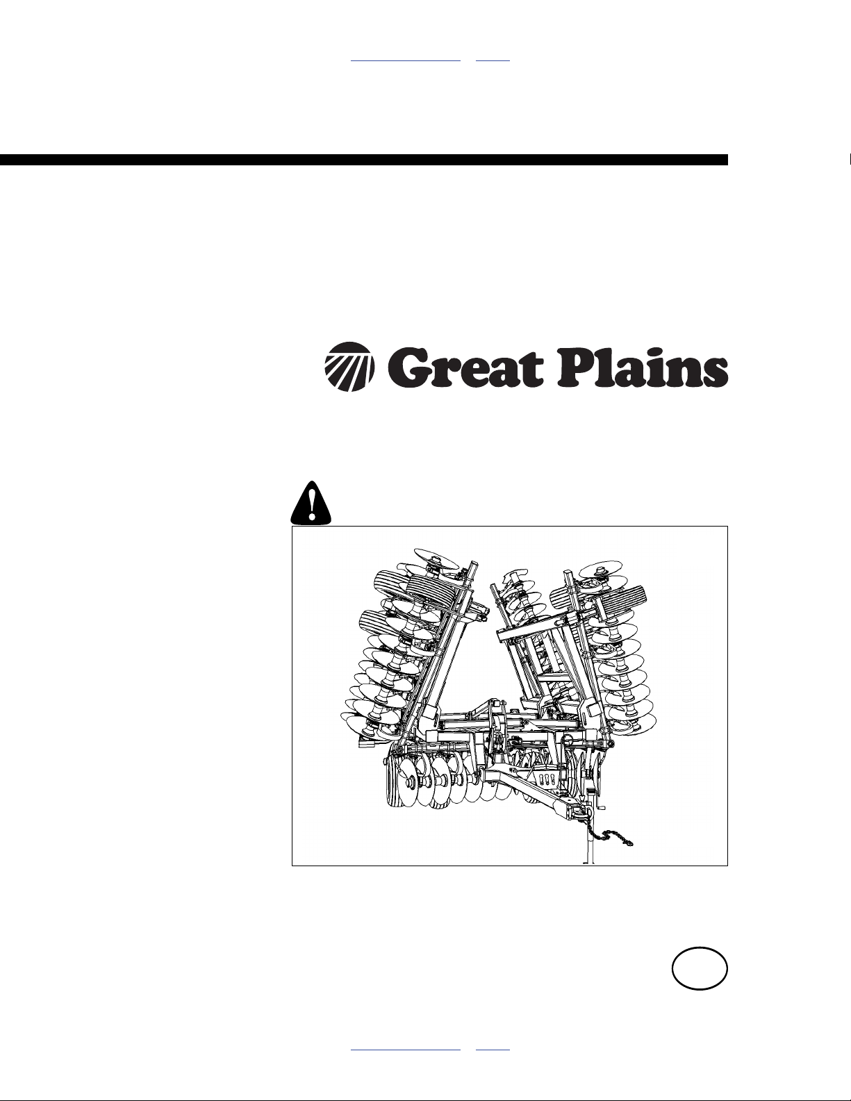
Table of Contents Index
Pre-Delivery Manual
Series I 3323, 3326, 3329,
4330, 4333 & 4336
Disk Harrow
Manufacturing, Inc.
www.greatplainsmfg.com
Read the operator’s manual entirely. When you see this symbol, the
subsequent instructions and warnings are serious - follow without
exception. Your life and the lives of others depend on it!
Illustrations may show optional equipment not supplied with standard unit.
42101
ORIGINAL INSTRUCTIONS
© Copyright 2012 Printed 2012-05-22 556-100Q
Table of Contents Index
EN

Table of Contents Index
Table of Contents Index

Great Plains Manufacturing, Inc. Cover Index iii
Table of Contents
Important Safety Information ...................................... 1
Introduction ..................................................................4
Description of Unit ..........................................................4
Models Covered ............................................................. 4
Document Family ...........................................................4
Tools Required ...............................................................4
Pre-assembly Checklist..................................................4
Using This Manual..........................................................5
Definitions................................................................... 5
Shipping .........................................................................6
Unloading ....................................................................... 6
Unload Smaller Items First .........................................6
Unload Disk Harrow....................................................6
Unpacking Boxes .......................................................6
Assembly and Setup Assistance ................................6
Assembly ......................................................................7
Narrow Center Hub and Wheel Assembly.................. 7
Wide Center Frame Assembly....................................8
Center Frame Gang Assembly...................................9
3323-3326 Wing Hub and Wheel Assembly............. 10
Narrow Hitch and Lever Link Assembly....................11
Wide Center Hitch and Cylinder Assembly...............12
3329-4336 Wing Assembly.......................................14
Hydraulic Assembly..................................................15
Attach Hose Clamps and Hose wraps...................... 17
Hydraulic Hose Hookup............................................ 17
Hose Handles...........................................................17
Purging Hydraulic System ........................................18
Narrow Center Light Brackets and SMV Assembly..19
Wide Center Light Brackets and SMV Assembly .....20
Gauge Wheel ...........................................................21
C-Shank Alignment-Disc Gang Assembly................21
Level Bar Cap Orientation ........................................22
Install Rear Hitch (optional) ......................................23
Appendix - Reference Information ...........................24
Torque Values Chart.................................................... 24
Tire Inflation & Warranty .............................................. 25
Hydraulic Connectors and Torque ............................... 26
Narrow Center Hydraulic Lift Layout ............................ 27
Wide Center Hydraulic Lift Layout ............................... 28
3323 Hydraulic Fold Layout ......................................... 29
3326-4336 Hydraulic Fold Layout ................................ 30
Hydraulic Hitch Level Layout (Optional)....................... 31
3323DH Machine Layout ............................................. 32
3323DH Machine Layout ............................................. 33
3326DH Machine Layout ............................................. 34
3326DH Machine Layout ............................................. 35
3329DH Machine Layout ............................................. 36
3329DH Machine Layout ............................................. 37
4330DH Machine Layout ............................................. 38
4330DH Machine Layout ............................................. 39
4333DH Machine Layout ............................................. 40
4333DH Machine Layout ............................................. 41
4336DH Machine Layout ............................................. 42
4336DH Machine Layout ............................................. 43
3323DH S3T Spike Drag HR Layout ........................... 44
3323DH 3 Bar Heavy Coil Tine Layout ........................ 45
3326DH S3T Spike Drag HR Layout ........................... 46
3326DH 3 Bar Heavy Coil Tine Layout ........................ 47
3329DH S3T Spike Drag HR Layout ........................... 48
3329DH 3 Bar Heavy Coil Tine Layout ........................ 49
4330DH S3T Spike Drag HR Layout ........................... 50
4330DH 3 Bar Heavy Coil Tine Layout ........................ 51
4333DH S3T Spike Drag HR Layout ........................... 52
4333DH 3 Bar Heavy Coil Tine Layout ........................ 53
4336DH S3T Spike Drag HR Layout ........................... 54
4336DH 3 Bar Heavy Coil Tine Layout ........................ 55
Index........................................................................... 57
© Copyright 2006, 2007, 2008, 2009, 2010, 2011, 2012 All rights Reserved
Great Plains Manufacturing, Inc. provides this publication “as is” without warranty of any kind, either expressed or implied. While every precaution has been
taken in the preparation of this manual, Great Plains Manufacturing, Inc. assumes no responsibility for errors or omissions. Neither is any liability assumed for
damages resulting from the use of the information contained herein. Great Plains Manufacturing, Inc. reserves the right to revise and improve its products as
it sees fit. This publication describes the state of this product at the time of its publication, and may not reflect the product in the future.
05/22/2012 Cover Index 556-100Q
Trademarks of Great Plains Manufacturing, Inc. include: Singulator Plus, Swath Command, Terra-Tine.
Registered Trademarks of Great Plains Manufacturing, Inc. include:
Air-Pro, Clear-Shot, Discovator, Great Plains, Land Pride, MeterCone, Nutri-Pro, Seed-Lok, Solid Stand,
Terra-Guard, Turbo-Chisel, Turbo-Chopper, Turbo Max, Turbo-Till, Ultra-Till, Verti-Till, Whirlfilter, Yield-Pro.
Brand and Product Names that appear and are owned by others are trademarks of their respective owners.
Printed in the United States of America

iv 3323-4336DH Table of Contents Index Great Plains Manufacturing, Inc.
556-100Q Table of Contents Index 05/22/2012

Great Plains Manufacturing, Inc. Table of Contents Index 1
Important Safety Information
Look for Safety Symbol
The SAFETY ALERT SYMBOL indicates there is a
potential hazard to personal safety involved and extra
safety precaution must be taken. When you see this
symbol, be alert and carefully read the message that follows it. In addition to design and configuration of equipment, hazard control and accident prevention are
dependent upon the awareness, concern, prudence and
proper training of personnel involved in the operation,
transport, maintenance and storage of equipment.
Be Aware of Signal Words
Signal words designate a degree or level of hazard seriousness.
DANGER indicates an imminently hazardous situation
which, if not avoided, will result in death or serious injury.
This signal word is limited to the most extreme situations,
typically for machine components that, for functional purposes, cannot be guarded.
WARNING indicates a potentially hazardous situation
which, if not avoided, could result in death or serious
injury, and includes hazards that are exposed when
guards are removed. It may also be used to alert against
unsafe practices.
CAUTION indicates a potentially hazardous situation
which, if not avoided, may result in minor or moderate
injury. It may also be used to alert against unsafe practices.
Use Adequate Lifting Means
The frame sections and gangs of this machine are
extremely heavy. If using multiple lifters, make sure each
is rated for at least its share of the load.
> 14,000
POUNDS
Prepare for Emergencies
▲ Be prepared if a fire starts
▲ Keep a first aid kit and fire extinguisher handy.
▲ Keep emergency numbers for doctor, ambulance, hospital
and fire department near phone.
05/22/2012 Table of Contents Index 556-100Q
2 3323-4336DH Table of Contents Index Great Plains Manufacturing, Inc.
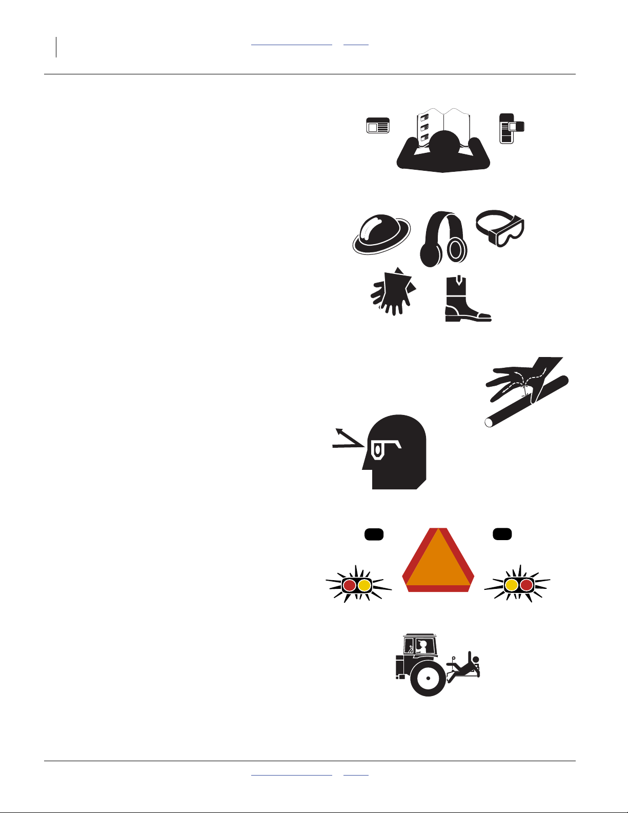
Be Familiar with Safety Decals
▲ Read and understand the “Safety Decals” section of the
Operators Manual.
▲ Read all instructions noted on the decals.
▲ Keep decals clean. Replace damaged, faded and illegible
decals.
Wear Protective Equipment
▲ Wear protective clothing and equipment.
▲ Wear clothing and equipment appropriate for the job. Avoid
loose-fitting clothing.
▲ Because prolonged exposure to loud noise can cause hear-
ing impairment or hearing loss, wear suitable hearing protection such as earmuffs or earplugs.
▲ Because operating equipment safely requires your full
attention, avoid wearing entertainment headphones while
operating machinery.
Avoid High Pressure Fluids
Escaping fluid under pressure can penetrate the skin,
causing serious injury.
▲ Avoid the hazard by relieving pressure before disconnecting
hydraulic lines.
▲ Use a piece of paper or cardboard, NOT BODY PARTS, to
check for suspected leaks.
▲ Wear protective gloves and safety glasses or goggles when
working with hydraulic systems.
▲ If an accident occurs, seek immediate medical assistance
from a physician familiar with this type of injury.
Use Safety Lights and Devices
Slow-moving tractors and towed implements can create
a hazard when driven on public roads. They are difficult
to see, especially at night.
▲ Use flashing warning lights and turn signals whenever driv-
ing on public roads.
Use lights and devices provided with implement
Keep Riders Off Machinery
Riders obstruct the operator’s view. Riders could be
struck by foreign objects or thrown from the machine.
▲ Never allow children to operate equipment.
▲ Keep all bystanders away from machine during operation.
556-100Q Table of Contents Index 05/22/2012
Great Plains Manufacturing, Inc. Table of Contents Index Important Safety Information 3
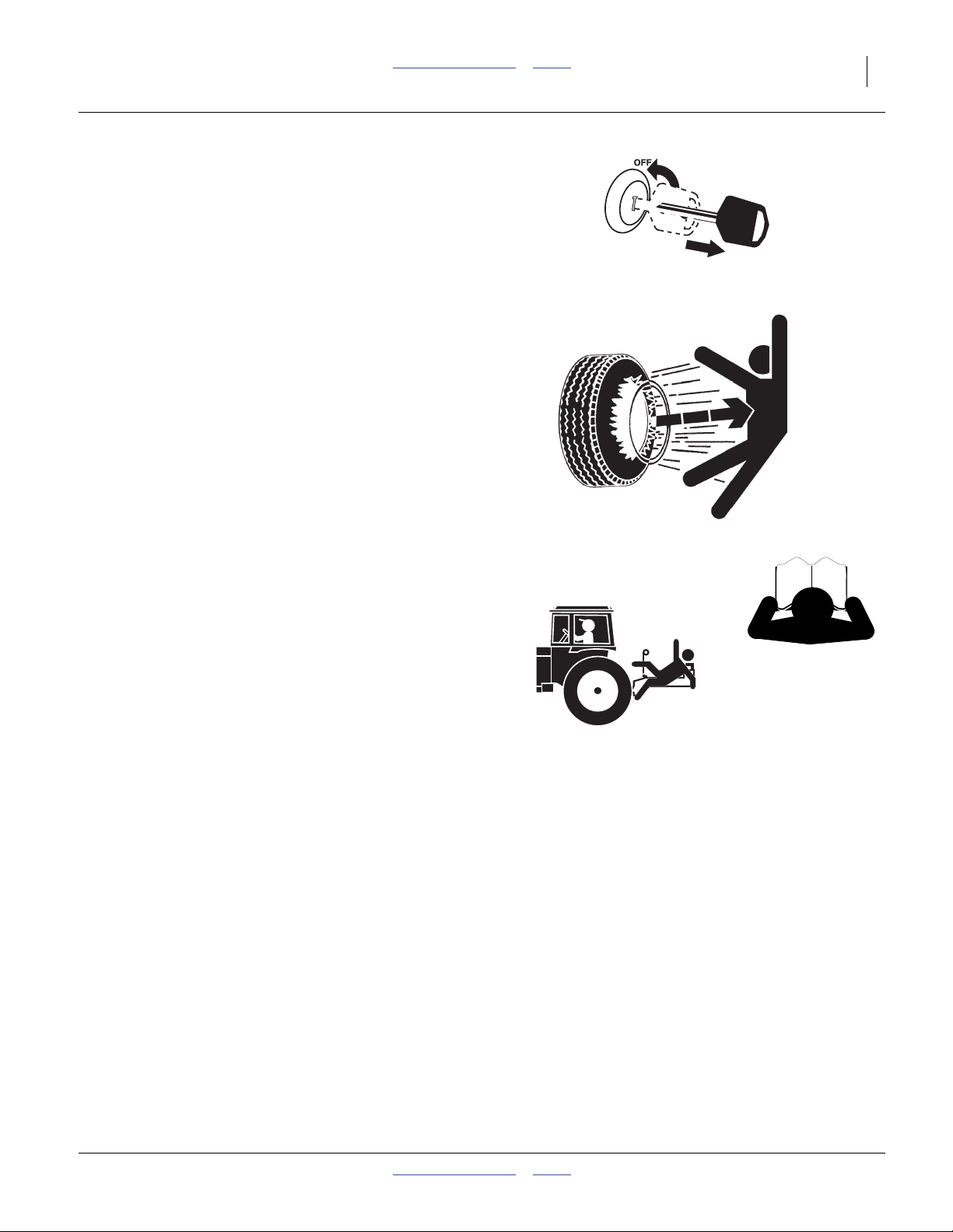
Shutdown and Storage
▲ Lower implement, put tractor in park, turn off engine, and
remove the key.
▲ Secure Disk Harrow using blocks and supports provided.
▲ Detach and store Disk Harrow in an area where children
normally do not play.
Tire Safety
Tire changing can be dangerous and should be performed by trained personnel using correct tools and
equipment.
▲ When inflating tires, use a clip-on chuck and extension hose
long enough for you to stand to one side–not in front of or
over tire assembly. Use a safety cage if available.
▲ When removing and installing wheels, use wheel-handling
equipment adequate for weight involved.
Safety At All Times
Thoroughly read and understand the instructions in this
manual before operation. Read all instructions noted on
the safety decals.
▲ Be familiar with all machine functions.
▲ Operate machinery from the driver’s seat only.
▲ Do not leave machine unattended with tractor engine run-
ning.
▲ Do not stand between the tractor and machine during
hitching.
▲ Keep hands, feet and clothing away from power-driven
parts.
▲ Wear snug-fitting clothing to avoid entanglement with mov-
ing parts.
▲ Watch out for wires, trees, etc., when folding and raising
machine. Make sure all persons are clear of working area.
05/22/2012 Table of Contents Index 556-100Q
4 3323-4336DH Table of Contents Index Great Plains Manufacturing, Inc.
Introduction
The Disk Harrow has been designed with care and built
by skilled workers using quality materials. Proper setup,
maintenance, and safe operating practices will help the
customer get years of satisfactory use from the machine.
Description of Unit
The Series I 3323-4336DH Disk Harrow is a three section
primary and secondary tillage tool. Working width ranges
from 23 to 36 feet. The implement is designed to cut out
and bury roots and crop residue, kill weeds and dry out
the soil, level ridges and ruts and for seedbed preparation. Various finishing attachments are also available to
further smooth, redistribute residue, kill weeds, and break
clods
Models Covered
3323DH 23-Foot 3-section
3326DH 26-Foot 3-section
3329DH 29-Foot 3-section
4330DH 30-Foot 3-section
4333DH 33-Foot 3-section
4336DH 36-Foot 3-section
Document Family
556-100Q Pre-Delivery Manual (this document)
556-100M Operator Manual
556-100P Parts Manual
Tools Required
• Basic Hand Tools
• Torque Wrench
• Fork Truck, Overhead Hoist or Loader
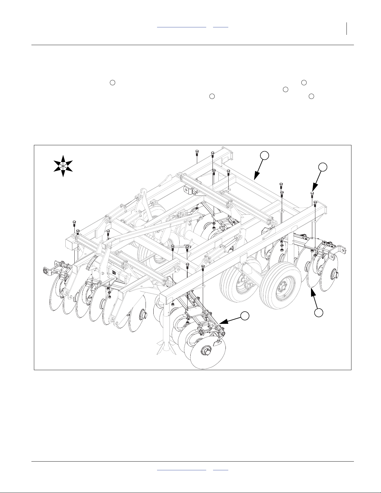
Pre-assembly Checklist
1. Before assembling, read and understand “Important
Safety Information” in front part of this manual.
2. Have at least two people on hand while assembling.
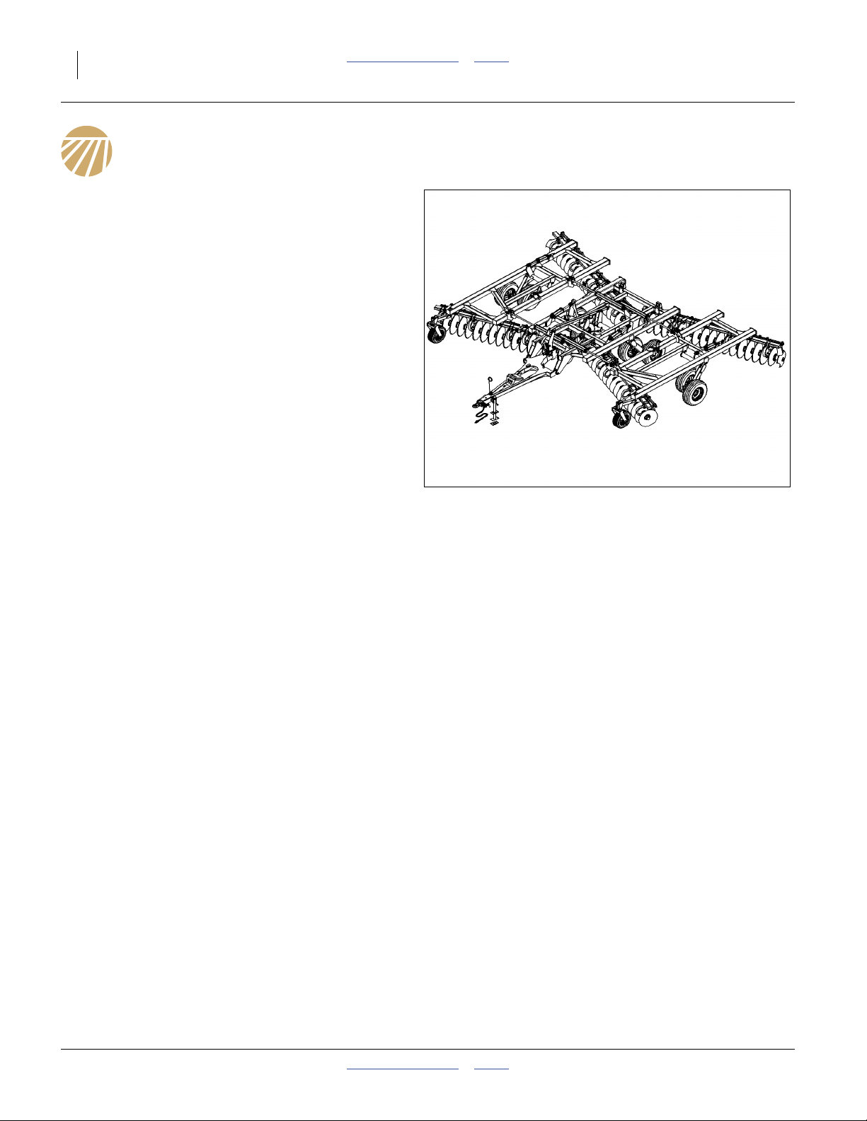
Figure 1
3326 Disk Harrow
3. Make sure area is level and free of obstructions
(preferably an open concrete area).
4. Have all major componets
5. Have all fasteners and pins shipped with machine.
42100
556-100Q Table of Contents Index 05/22/2012
Great Plains Manufacturing, Inc. Table of Contents Index Introduction 5
Using This Manual
This manual was written to help you assemble and prepare the new machine for the customer. The manual
includes instructions for assembly and setup. Read this
manual and follow the recommendations for safe, efficient
and proper assembly and setup.
An operator’s and parts manual is also provided with the
new machine. Read and understand “Important Safety
Information” and “Operating Instructions” in the operator’s manual before assembling the machine. Refer to the
parts manual for proper part’s identification. As a reference, keep the operator’s and part’s manual on hand while
assembling.
The information in this manual is current at printing. Some
parts may change to assure top performance.
Definitions
The following terms are used throughout this manual.
A crucial point of information related to the preceding topic. Read
and follow the directions to remain safe, avoid serious damage to
equipment and ensure desired field results.
Note: Useful information related to the preceding topic.
Right-hand and left-hand as used in
this manual are determined by facing
the direction the machine will travel
while in use unless otherwise stated.
An orientation rose in some line art
illustrations shows the directions of: Up,
Back, Left, Down, Front, Right.
R
F
U
B
L
D
R
L
Figure 2
Right / Left
42100
05/22/2012 Table of Contents Index 556-100Q
6 3323-4336DH Table of Contents Index Great Plains Manufacturing, Inc.
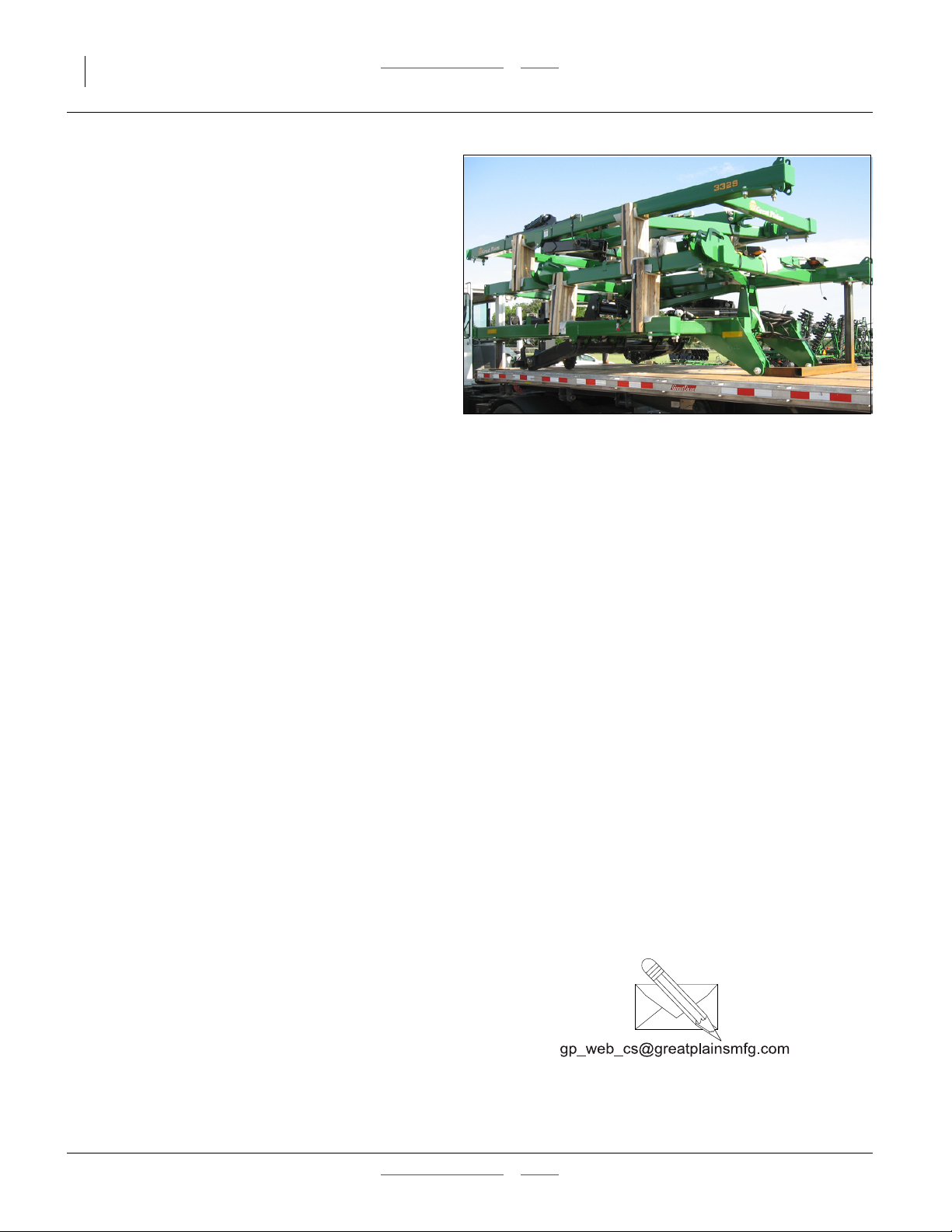
Shipping
The Disk Harrow will be shipped partially pre-assembled.
Refer to Figure 3
• The machine will be shipped with center frame and
wings stacked on stands and banded together.
• Finishing attachments (if equipped), will be will be
shipped with mounted brackets assembled and all
bolts will be in a box.
• Remove unit from shipping stands (if equipped), after
machine is lowered to ground and carefully un-band
all componets.
• The shipping stand bolts are not used in the assembly of unit.
• The shipping stands do not need to be returned to
Great Plains.
Figure 3
Disk Harrow Shipping
42137
Unloading
Be sure the truck is on level ground, preferably concrete.
Centering componets:
Be sure and center fork truck or chains (overhead hoist) on componets
so they won’t slide and cause injury.
Unload Smaller Items First
Unloading the Disk Harrow is a potentially dangerous
operation.
Reduce risk and complications by first unloading
1. the gangs and finishing attachments
2. the misc. boxes
3. the Disk Harrow
(described in the next section)
Unload Disk Harrow
4. Place these components well out of the manoeu-
vring area needed for unloading the Disk Harrow.
5. Double-check that all chains and tie-down straps
have been released and stowed.
6. Set parking brake on trailer tractor.
7. Slowly lift the Disk Harrow off trailer bed using two
fork lifts.
8. Stop lifting about 12” above the bed.
9. Have the truck driver slowly pull the trailer straight
out from under the Disk Harrow.
10. Making sure to keep level from front to back and side
to side, slowly lower the Disk Harrow.
11. Lower theDisk Harrow down until the machine is
about 12” off ground.
12. Remove shipping stands.
Unpacking Boxes
Note: Position boxes in area that you can maneuver
components up to machine to assembly.
13. Carefully remove banding from boxes.
14. Carefully remove banding from gangs and finishing
reels.
15. Locate and identify all componets before assembling.
Assembly and Setup Assistance
To order additional copies of pre-delivery instructions or
operator’s and parts manuals, write to the following
address. Include model numbers in all correspondence.
If you do not understand any part of this manual or have
the assembly or setup questions, assistance is available.
Contact:
Product Support
Great Plains Mfg. Inc., Service Department
PO Box 5060
Salina, KS 67402-5060
(800)255-9215
556-100Q Table of Contents Index 05/22/2012
Great Plains Manufacturing, Inc. Table of Contents Index 7
Assembly
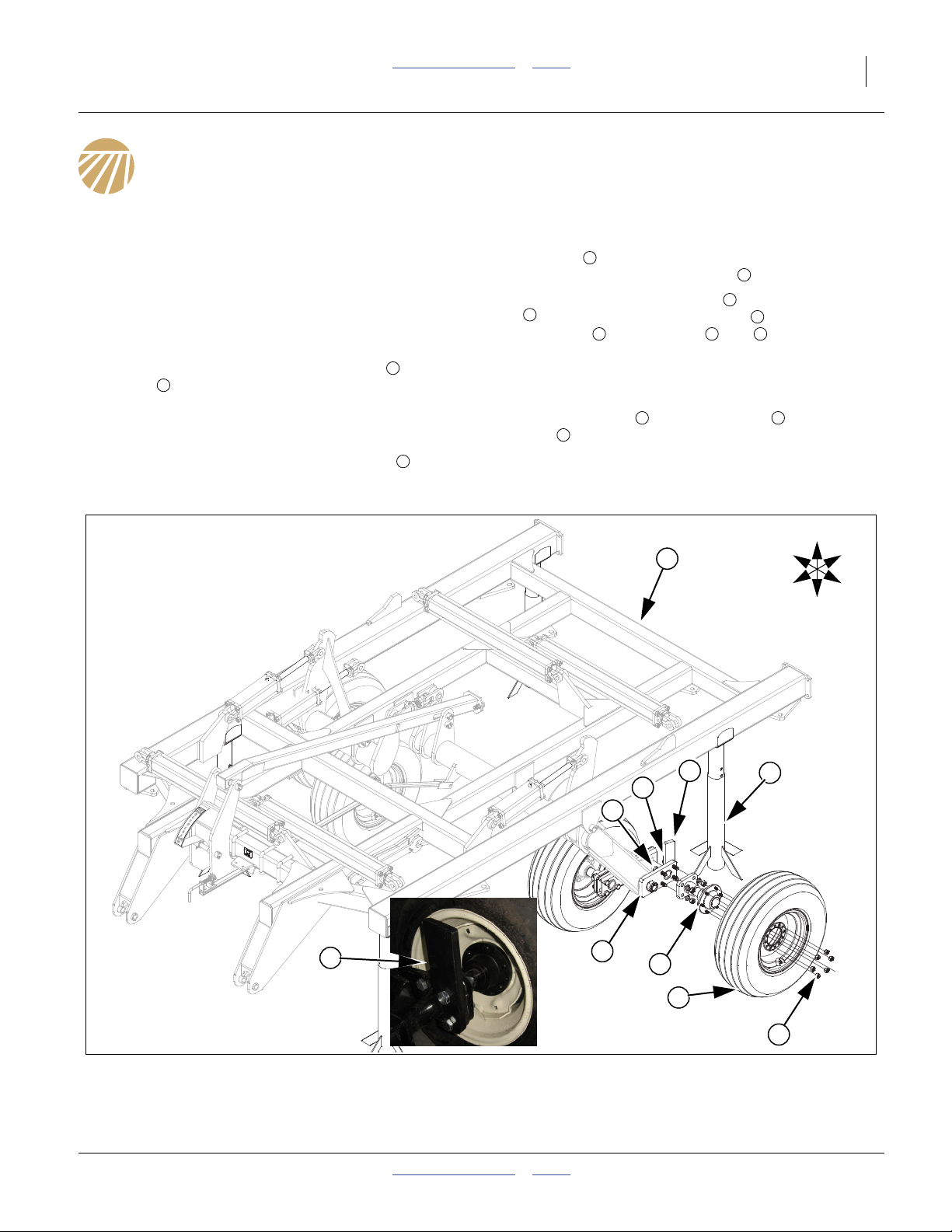
Narrow Center Hub and Wheel Assembly
Refer to Figure 4
Note: All bolts will be pre-installed on the unit in their
proper location. Bolts will need to be removed and
then re-installed during assembly. See “Parts
Manual” for complete break down of parts. For
4330-4336 models, skip to, See “Wide Center
Frame Assembly” on page 8.
1. Set pre-assembled center frame section on
stands that are tall enough to allow for installation
of the pre-assembled gang bars as shown. Model
3329 will be the same as models 4330-4336, See
“Wide Center Frame” on page 8.
Note: Be sure and get the walking beam stop
2
installed on back side (rear holes) of walking
1
3
beam as shown in inset picture. Be sure tab or
notch of hub assembly plate is installed on top.
2. Remove the 3/4x4hexbolts and 3/4x3hexbolts
5
. Bolt he hub/spindle assembly to walking beam
assembly with the bolts and , secure with 3/4
lock washers and 3/4 nuts.
Note: The center uses 11l-5 load range F tires while the
wings have 11L-15 8 ply tires.
3. Instal tire/wheel to hub assembly with 9/16 lug
nuts .
4. Bolts may be tightened to specs, See “Torque Val-
ues Chart” on page 24.
6
7
4
7
6 4 5
8 7
9
U
1
R
F
B
L
D
3
2
4
5
3
6
7
8
9
Figure 4
Narrow Center Hub and Wheel
05/22/2012 Table of Contents Index 556-100Q
42131
42135
8 3323-4336DH Table of Contents Index Great Plains Manufacturing, Inc.
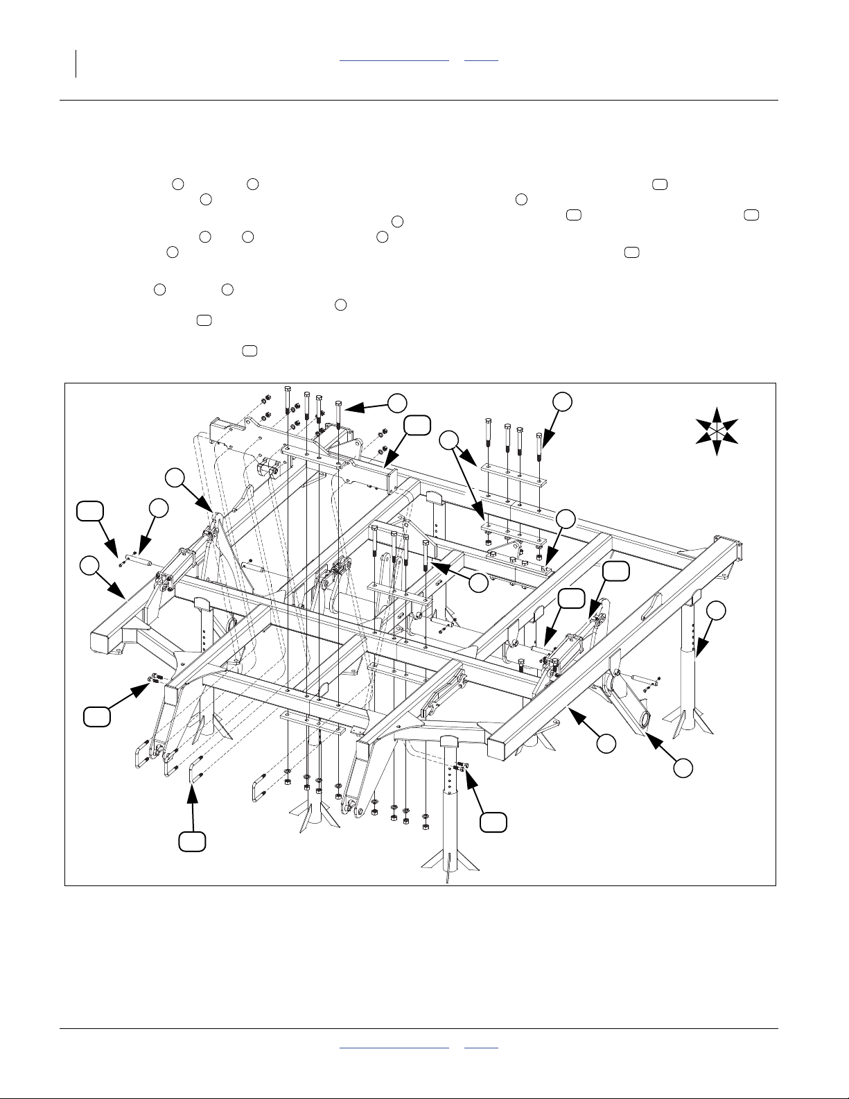
Wide Center Frame Assembly
Refer to Figure 5
5. Lower the left and right halves of the center
frame onto stands .
6. Install the bolts loose through the 4-hole tie plates
and center frames and with1x8hexbolts , 1
x 9 hex bolts , 1 lock washers and 1 nuts. Do not
tighten at this time.
7. Pin the LH and RH torque tube weldments to
the center frames with 1 1/4 x 8 3/4 pins (outer)
and 1 1/4 x 7 pins (center) (be sure nylon sleeves
are installed on pins). Secure pins with 3/8 x 2 1/4
Gr. 8 special thread bolts and 3/8 top lock nuts.
1 2
3
1 2 5
6
7 8
10
11
8. Bolt on wide center fold bracket with four 1 x 8
hex bolts , 1 lock washers and 1 nuts, four 1 x 5 1/
4
9
32 x 6 1/2 u-bolts , four 3/4 x 2 1/2 hex bolts , 3/
4 lock washers and 3/4 nuts.
9. Fasten center lift cylinders , base end to center
frame and rod end to torque tube with 1 pins,
machine washers and cotter pins, provided.
10. Tighten all bolts to specs, See “Torque Values
Chart” on page 24.
5
13
12
14
15
11
2
14
5
5
12
4
R
F
U
B
L
D
8
9
4
15
6
10
3
1
7
14
13
Figure 5
Wide Center Frame
556-100Q Table of Contents Index 05/22/2012
41001
Great Plains Manufacturing, Inc. Table of Contents Index Assembly 9
Center Frame Gang Assembly
Refer to Figure 6
Note: The gang assemblies will be marked on the top
plates as to the location on disk as “left, front, center”. This would refer to the left, front gang on the
center section. You may also refer to the machine
layout section for placement. The gang assembly
will be the same on both the narrow and wide center except the wing hinge will be opposite on wide
center.
1 3
11. Remove the 1 x 3 Gr. 8 hex bolts . Align holes in
plates of gang assemblies to center frame plates
2 3
, secure with 1 x 3 Gr. 8 hex bolts , 1 lock wash-
ers and 1 nuts.
12. Bolt may be tightened to specs, See “Torque Values
Chart” on page 24.
1
R
F
U
D
B
L
2
3
1
1
Figure 6
Center Frame Gangs
05/22/2012 Table of Contents Index 556-100Q
42132
10 3323-4336DH Table of Contents Index Great Plains Manufacturing, Inc.
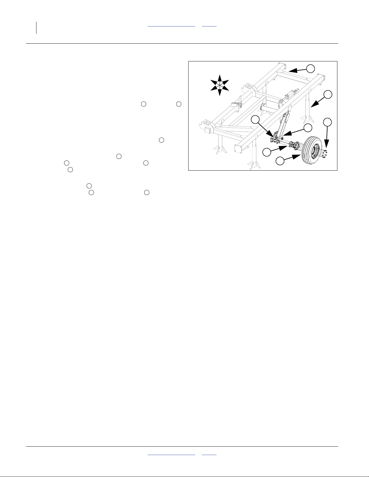
3323-3326 Wing Hub and Wheel Assembly
Refer to Figure 7
Note: Remove the assembly stands from center section and
allow unit to rest on the ground in the center of work area.
13. Set pre-assembled wing frame section on stands
that are tall enough to allow for installation of the preassembled gang bars as shown. Model 3329 will be the
same as models 4330-4336, See “3329-4336 Wing” on
page 14.
Note: Be sure tab or notch of hub assembly plate is in-
stalled on top.
14. Remove the 3/4 x 3 hex bolts . Bolt the hub/spindle
assembly to walking beam assembly with the 3/4 x
3 hex bolts , secure with 3/4 lock washers and 3/4
nuts.
Note: Instal tire/wheel (11L-15, 8-ply tire/wheel assembly)
to hub assembly with 9/16 lug nuts .
15. Bolts may be tightened to specs, See “Torque Values
Chart” on page 24
3 5
4
6
3 7
4
1 2
3
U
R
F
B
L
D
4
3
Figure 7
3323-3326 Wing Hub and Wheel
6
1
2
7
5
41617
556-100Q Table of Contents Index 05/22/2012
Great Plains Manufacturing, Inc. Table of Contents Index Assembly 11
Narrow Hitch and Lever Link Assembly
Note: For 4330-4336 models, skip to, See “Wide Cen-
ter Hitch and Cylinder Assembly” on page 12.
Refer to Figure 8
16. Install hitch assembly to front of center frame with
the 1 1/4 x 8 Gr. 8 hex bolts provided. Be sure and
install 1 1/4 flat washers as needed on both sides,
to insure a tight fit (be sure and have same amount
on both sides of hitch). Secure with the 1 1/4 top lock
nuts. Bolts need to be tightened down securely on
the ball joints but do not torque as hitch needs to
pivot freely.
17. Remove the tongue jack from its storage location
5
at rear of hitch and install it on the jack stub at the
front of the hitch frame to support the front side of
hitch.
18. Connect the bottom of leveling turnbuckle or
hydraulic cylinder to rear of hitch with 1 x 6 Gr. 8
special thread bolt , and 1 nylon lock nut, (do not
torque bolt), top to middle hole of leveler assembly
1
2
3
4
6
7
8
with the 1 x 9 1/2 hinge pin , 3/8 x 2 1/4 Gr. 8 hex
bolt and 3/8 top lock nut.
10
19. Attach spring hose loop to front of hitch assembly
1
with 1/2 x 1 1/2 hex bolt , 1/2 flat washer, 1/2
lock washer and 1/2 nut.
20. Attach level gauge pointer over tube on right side
of leveler assembly, secure with 2.25 x 1.50 x 10ga
machine washer and 3/16 x 2 cotter pin .
21. Connect level gauge link , bottom side with extra
bend through hole in back of hitch, top side through
hole in level gauge pointer. Secure with 3/8 flat
washers and 1/8 x 1 cotter pins .
22. Bolts may be tightened to specs, See “Torque Val-
ues Chart” on page 24.
17 18
14 15
9
11
12
13
16
R
F
U
D
9
B
6
10
L
7
2
11
8
12
5
14
15
13
3
1
17
4
16
18
Figure 8
Narrow Hitch & Leveler Link
05/22/2012 Table of Contents Index 556-100Q
42136
42130

12 3323-4336DH Table of Contents Index Great Plains Manufacturing, Inc.
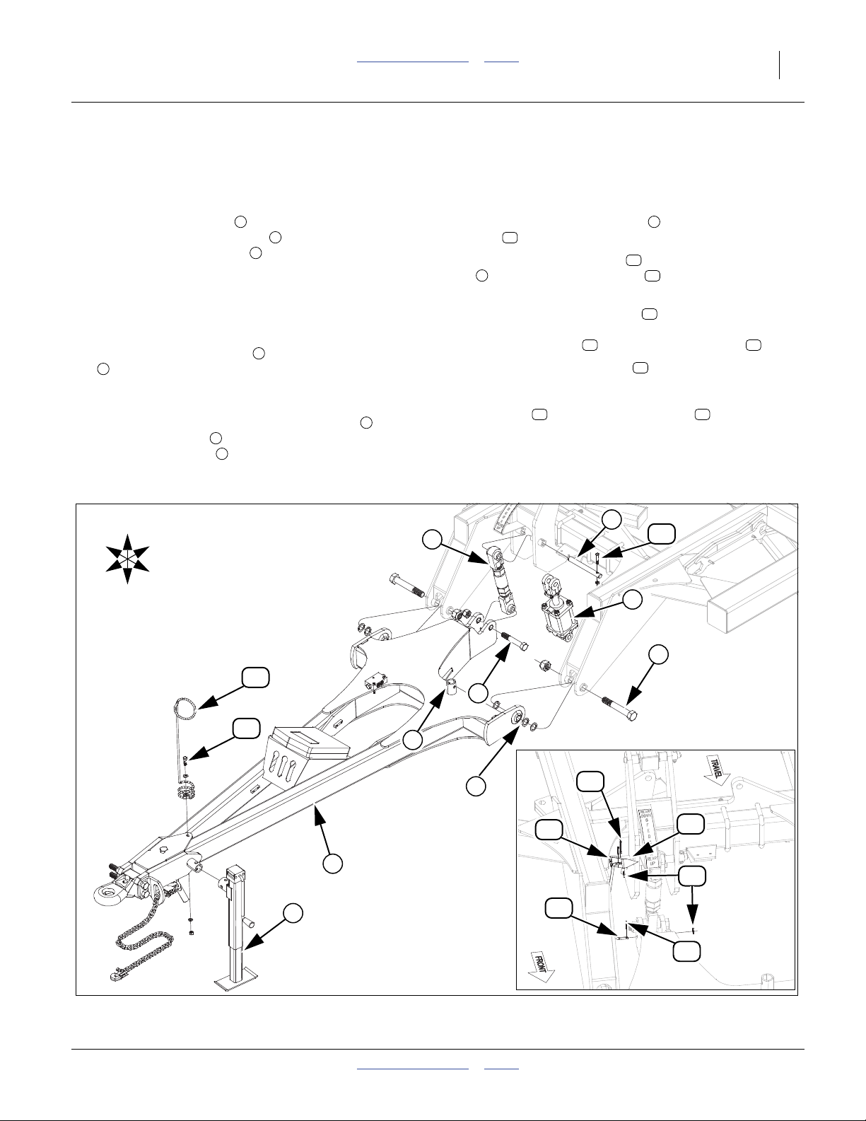
Wide Center Hitch and Cylinder Assembly
Refer to Figure 9
Note: See hydraulic layouts for complete layout of
hydraulics.
23. Attach the hydraulic fold cylinders to the center
1
frame as shown. (Fittings direction toward inside of
machine), using clevis pins provided. Always use
2
machine washer next to cotter pin.
24. Attach level bracket to the front of center frame
with 1 x 9 Gr. 8 hex bolts , and nylon lock nut.
25. Connect level bar between level bracket and
torque tube with1x7pin and1x9Gr.8hexbolt
7
with nylon lock nut. Secure pin with 3/8 x 2 1/4 Gr.
3
4
5
6
3
8 hex bolts and 3/8 top lock nuts. Secure the 1 x 9
Gr. 8 hex bolt with 1 nylon lock nut. Do not torque
7
bolts.
26. Install lift turnbuckle between torque tubes with 1
x 3 3/8 usable clevis pins , machine washer and
8
9
cotter pin. Adjust to initial length of 13 3/16” pin centers and tighten jam nut.
27. Install hitch assembly to front of center frame
with the 1 1/4 x 8 Gr. 8 hex bolts provided. Be
sure and install 1 1/4 flat washers as needed on
10
11
12
both sides, to insure a tight fit (be sure and have
same amount on both sides of hitch). Secure with
the 1 1/4 top lock nuts. Bolts need to be tightened
down securely on the ball joints.
28. Remove the tongue jack from its storage location
at rear of hitch and install it on the jack stub at the
14
13
front of the hitch frame to support the front side of
hitch.
29. Connect the bottom of leveling turnbuckle or
hydraulic cylinder to rear of hitch with 1 x 6 Gr. 8
special bolt 1 nylon lock nut, top to middle hole of
16
17
leveler assembly with 1 x 9 1/2 hinge pin , 3/8 x 2
1/4 Gr. 8 hex bolt and 3/8 top lock nut. Do not
19
15
18
torque bolts.
30. Attach spring hose loop to front of hitch assembly
with 1/2 x 1 1/2 hex bolt , 1/2 flat washer, 1/2
10 21
20
lock washer and 1/2 nut.
31. Attach level gauge pointer over tube on right side
22
of leveler assembly, secure with 2.25 x 1.50 x 10ga
machine washer and 3/16 x 2 cotter pin.
32. Connect level gauge link , bottom side with extra
23
bend through hole in back of hitch, top side through
hole in level gauge pointer. Secure with 3/8 flat
washers and 1/8 x 1 cotter pins.
33. Tighten all bolts to specs, See “Torque Values
Chart” on page 24.
556-100Q Table of Contents Index 05/22/2012
Great Plains Manufacturing, Inc. Table of Contents Index Assembly 13
U
R
B
F
L
D
9
1
6
2
5
8
7
11
23
22
3
19
18
4
15
16
20
21
17
14
12
11
12
10
13
Figure 9
Wide Center Hitch and Cylinders
05/22/2012 Table of Contents Index 556-100Q
41002
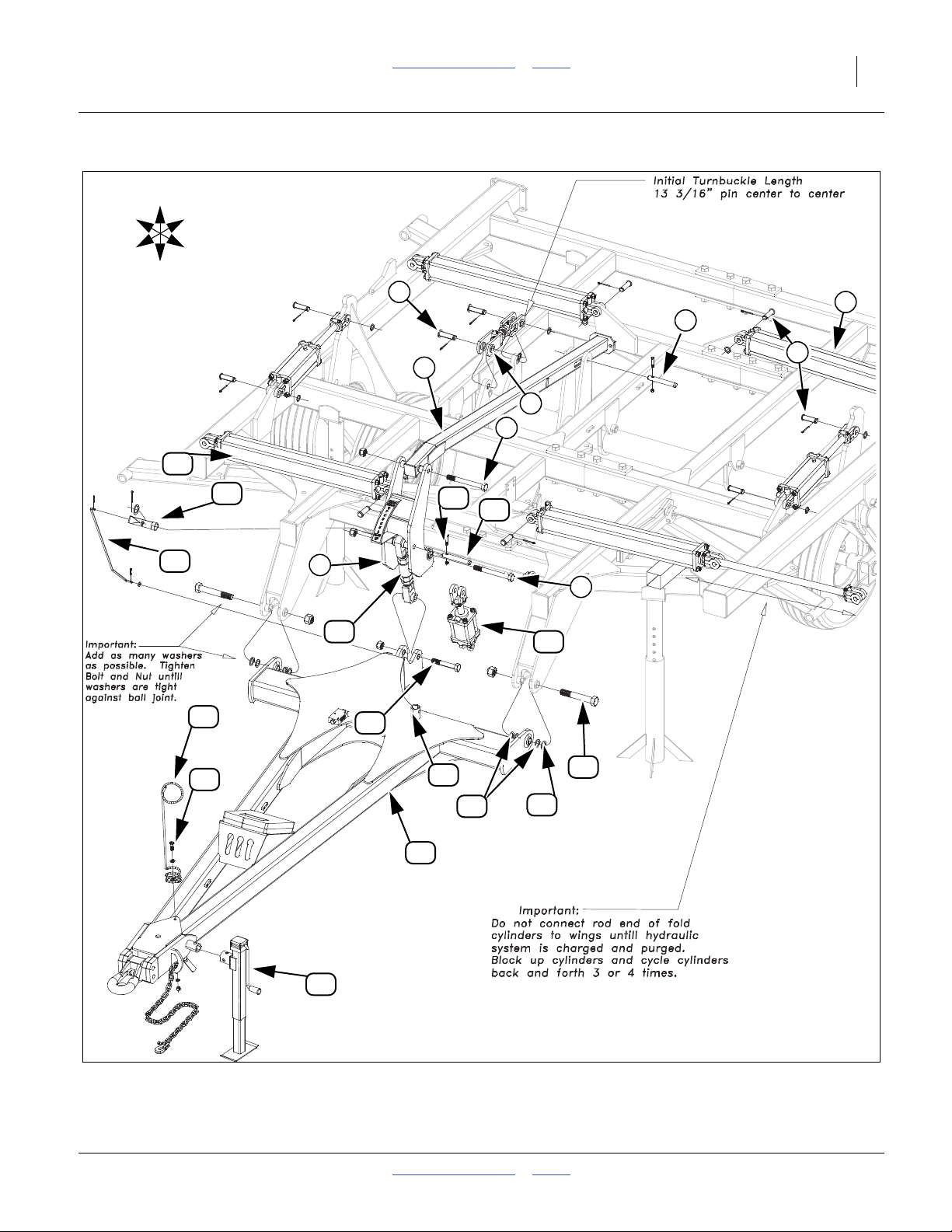
14 3323-4336DH Table of Contents Index Great Plains Manufacturing, Inc.
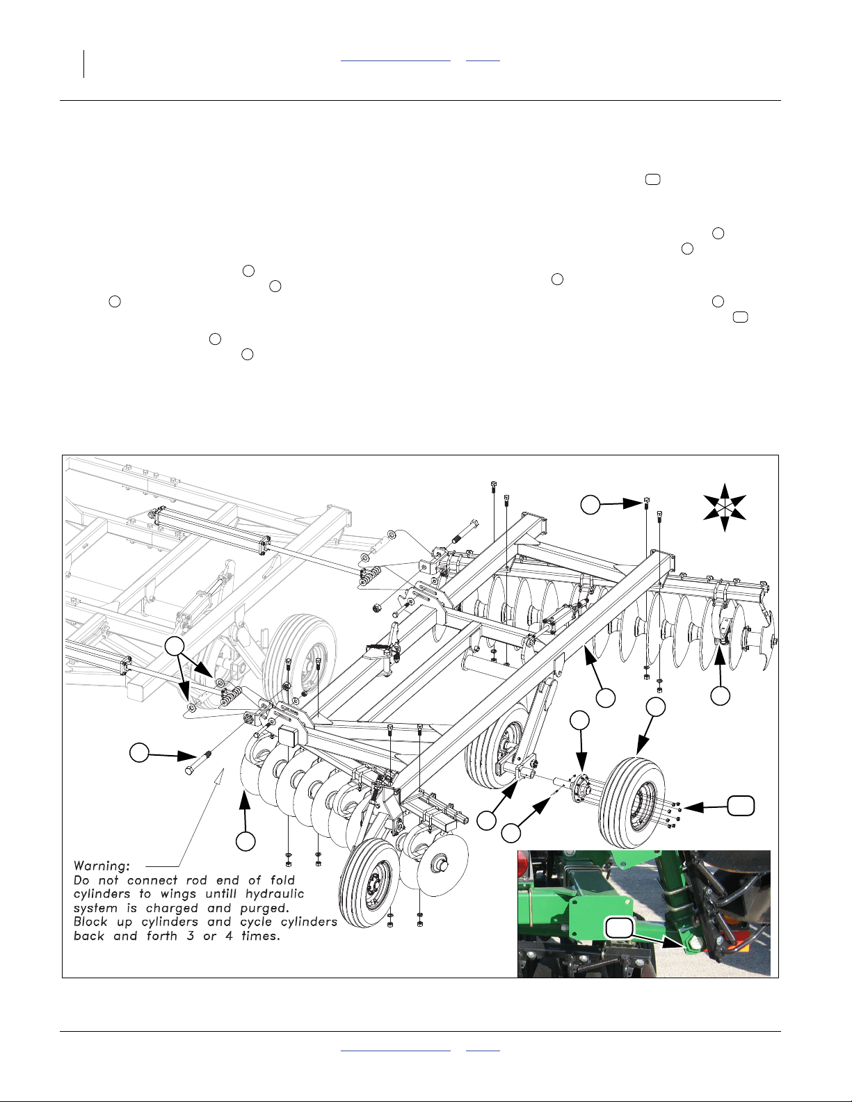
3329-4336 Wing Assembly
Note: The wing assembly will be the same on both the
narrow and wide center except the wing hinge will
be opposite on narrow center. Wide center shown.
Refer to Figure 10
34. With the center frame stands removed, the center
frame gangs should be resting on the floor.
35. Connect the wing gangs to the center gang bars
using the 1 1/2 x 13 hex bolts , two 1 1/2 flat wash-
3
ers (one on each side) and 1 1/2 nylon lock nut.
Snug bolts but do not torque as wing must pivot.
36. Set the wing frame on the gang bars and attach
with 1 x 3 Gr. 8 hex bolts , 1 lock washers and 1
nuts.
Note: Do not hook up rod end of fold cylinder until sys-
tem purged of air. See “Purging Hydraulic Sys-
tem” on page 18.
1
2
4
5
Bolts must be installed so the head of the bolt is in the
bolt stop as shown in inset picture .
37. Bolt the 8-bolt hub and spindle assembly (if not
installed), to the wing walking beam (tab or notch
needs to be assembled towards top) with 5/16 x 4
Gr. 8 hex bolts and 5/16 top lock nut.
38. Mount the 8-bolt tire and wheel assembly onto the
hubs (valve stem outward) with 5/8” lug nuts .
39. Tighten all bolts to specs, See “Torque Values
Chart” on page 24.
40. Repeat the same procedure for the other wing.
8
11
6
7
9
10
U
R
B
5
F
L
D
3
4
9
1
6
2
10
7
1
8
11
Figure 10
3329-4336 Wing
556-100Q Table of Contents Index 05/22/2012
41615
42138

Great Plains Manufacturing, Inc. Table of Contents Index Assembly 15
Hydraulic Assembly
Note: The brackets and hose clamps for mounting the hoses
to the scrapers are in a box shipped with the unit. See
hydraulic layouts in “Operators Manual” for complete
hose routings. When connecting these hoses, route the
hoses through the machine, as shown in the following
pictures
Refer to Figure 11
41. Connect the hoses from the center section to the wing, lift
cylinders. The hose and the fitting that are to be connected have a colored tie to assist in connecting the
proper hose to the proper fitting. (To double check this
hose routing, make sure the hose connected to the rod
end of the main lift cylinder on the center-frame, connects
to the base end of the cylinder on the wing.) Connect the
hose to the fitting that does not have the colored ties.
2
1
R
F
U
D
B
2
L
1
4
Refer to Figure 12
42. Route the hoses along scraper bar tubes as shown.
Secure with hose clamps. Be sure to allow some extra
hose at the hinge line to allow for flexing during folding.
Mount hose holder scraper bracket to scraper tube
with 1/2 x 2 1/32 x 3 1/4 u-bolts and 1/2 flange nut.
Refer to Figure 13
Route hoses along wing frames as shown. Fasten hoses with
hose clamps and hose wraps as needed.
4
3
Figure 11
Hose Color Ties
3
Figure 12
Scraper Bar Hose Routing
4
42140
42141
Figure 13
Wing Hose Routing
05/22/2012 Table of Contents Index 556-100Q
42143
16 3323-4336DH Table of Contents Index Great Plains Manufacturing, Inc.
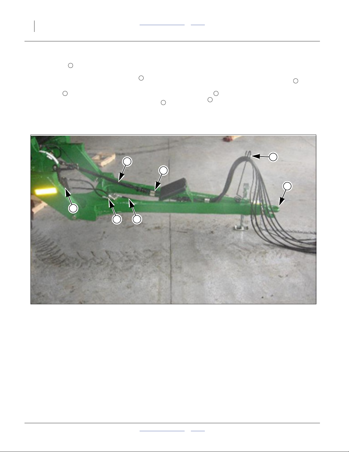
Refer to Figure 14
43. Route hoses for lift and fold systems from the front
of the main frame, along the left, inside tube on the
hitch and through the spring hose holder .
44. Approximately 3’ of hose should extend past the
hitch point .
45. Fasten hoses to hitch frame with bolts and clamps
(provided) on hitch frame.Attach hose wraps on
hoses to prevent hoses from dragging or getting
pinched.
1
2
3
46. See “Attach Hose Clamps and Hose wraps” on
page 17 for proper assembly.
47. If machine has optional hydraulic cylinder instead
of turnbuckle for leveling run hoses from cylinder to
lock valve and then along right side, inside of tube
4
of hitch .
48. When all hoses are clamped to frame, check that all
fittings are tight. You are ready to charge the hydraulic system.
5
6
4
1
2
4
3
4
5
6
Figure 14
Hitch Hose Routing
42144
556-100Q Table of Contents Index 05/22/2012
 Loading...