

Page 1
Installation Instructions
401-508A and 401-516A
Pressure Relief Kits
for 403-143K, 403-226K
and 403-174K Hoppers
Manufacturing, Inc.
www.greatplainsmfg.com
Read the operator’s manual entirely. When you see this symbol, the subsequent
instructions and warnings are serious - follow without exception. Your life and
!
the lives of others depend on it!
27352
Cover illustration shows a 401-508A 82 bu kit installed in a 403-143K hopper.
© Copyright 2007 Printed 12/28/2007 401-514M
Page 2

YP Pressure Relief Kits Great Plains Manufacturing, Inc.
Table of Contents
Important Safety Information.................................... 1
Introduction ................................................................ 3
Description of Unit........................................................ 3
Document Family ......................................................... 3
Kits Covered by this Manual ........................................ 3
Hoppers Which May Be Updated............................. 3
Using This Manual ....................................................... 4
Call-Outs .................................................................. 4
Definitions ................................................................4
Owner Assistance ........................................................ 4
Installation Instructions ............................................ 5
Before You Start .......................................................... 5
Tools Required............................................................. 5
Prepare Hopper ........................................................... 5
Dismount Hopper ......................................................... 6
Remove Old Door Slide ............................................... 7
Install Bottom Weldment .............................................. 7
Install New Door Slide.................................................. 8
Assemble Upper Pipe Support..................................... 9
Attach 150 bu Angle Brackets.................................. 9
Install 82 bu Upper Components ............................... 10
Remove Support for Drilling................................... 10
Mark Holes and Drill............................................... 10
Re-Install Strainer Support..................................... 11
Position Air Pipe..................................................... 11
Install Upper Pipe Support ..................................... 11
Install 150 bu Upper Components ............................. 12
Mark Holes for Drilling............................................ 12
Insert Pipe in Hopper .............................................13
Cap and Position Pipe ........................................... 13
Drill 150 bu Holes................................................... 13
Attach Upper 150 bu Support ................................ 14
Closeout..................................................................... 14
Appendix................................................................... 15
Torque Values............................................................ 15
Parts Lists .................................................................. 16
401-508A 82 bu Pressure Release Kit................... 16
401-508A Part Numbers .................................... 17
401-516A 150 bu Pressure Release Kit................. 18
401-516A Part Numbers .................................... 19
Existing Parts Affected........................................... 19
© Copyright 2007. All rights Reserved.
Great Plains Manufacturing, Inc. provides this publication “as is”without warranty of any kind, either expressed or implied. While every precaution has been taken in the preparation
of this manual, Great Plains Manufacturing, Inc. assumes no responsibility for errors or omissions. Neither is any liability assumed for damages resulting from the use of the information contained herein. Great Plains Manufacturing, Inc. reserves the right to revise and improve its products as it sees fit. This publication describes the state of this product at
the time of its publication, and may not reflect the product in the future.
The following are trademarks of Great Plains Mfg., Inc.: Application Systems, Ausherman, Land Pride, Great Plains
All other brands and product names are trademarks or registered trademarks of their respective holders.
401-514M 12/28/2007
Great Plains Manufacturing, Incorporated Trademarks
Printed in the United States of America.
Page 3
Great Plains Manufacturing, Inc. 1
Important Safety Information
Look for Safety Symbol
The SAFETY ALERT SYMBOL indicates there is a
potential hazard to personal safety involved and extra
safety precaution must be taken. When you see this
symbol, be alert and carefully read the message that follows it. In addition to design and configuration of equipment, hazard control and accident prevention are
dependent upon the awareness, concern, prudence and
proper training of personnel involved in the operation,
transport, maintenance and storage of equipment.
Be Aware of Signal Words
Signal words designate a degree or level of hazard seriousness.
DANGER indicates an imminently hazardous situation
which, if not avoided, will result in death or serious injury.
This signal word is limited to the most extreme situations,
typically for machine components that, for functional purposes, cannot be guarded.
WARNING indicates a potentially hazardous situation
which, if not avoided, could result in death or serious
injury, and includes hazards that are exposed when
guards are removed. It may also be used to alert against
unsafe practices.
CAUTION indicates a potentially hazardous situation
which, if not avoided, may result in minor or moderate
injury. It may also be used to alert against unsafe practices.
!
!
!
!
DANGER
WARNING
CAUTION
Be Familiar with Safety Decals
▲ Read and understand “Safety Reflectors and Decals”in
the Operator Manual.
▲ Read all instructions noted on the decals.
12/28/2007 401-514M
Page 4
2 YP Pressure Relief Kits Great Plains Manufacturing, Inc.
Practice Safe Maintenance
▲ Understand procedure before doing work. Use proper tools
and equipment. Refer to this manual for additional information.
▲ Work in a clean, dry area.
▲ Wear gloves when handling row cleaner tines.
▲ Make sure all moving parts have stopped and all system
pressure is relieved.
▲ Inspect all parts. Make sure parts are in good condition and
installed properly.
▲ Remove buildup of grease, oil or debris.
▲ Remove all tools and unused parts from implement before
operation.
OFF
Prepare for Emergencies
▲ Be prepared if a fire starts.
▲ Keep a first aid kit and fire extinguisher handy.
▲ Keep emergency numbers for doctor, ambulance, hospital
and fire department near phone.
Safety At All Times
▲ Thoroughly read and understand the instructions in this
manual before operation. Read all instructions noted on the
safety decals.
▲ Be familiar with all implement functions.
▲ Operate machinery from the driver’s seat only.
▲ Do not leave implement unattended with tractor engine
running.
▲ Wear snug-fitting clothing to avoid entanglement with mov-
ing parts.
911
401-514M 12/28/2007
Page 5
Great Plains Manufacturing, Inc. Introduction 3
Introduction
Description of Unit
These kits update older hoppers to the current pneumatic configuration, which includes a vertical pipe to
equalize pressure at the top of the hopper and at the
base of the seed mass. This allows the hydraulic fan to
run at higher speeds, and provides more consistent seed
flow at all pressures and seed delivery rates.
Document Family
401-514M Installation Instructions (this document)
Also update your Operator and Parts Manuals for correct
information on fan operations with updated hoppers, and
current replacement part data.
The information in this manual is current at printing.
Some parts may change to assure top performance.
R
Kits Covered by this Manual
Part
Number
401-508A YP 82 BU AIR RELEASE FLD KIT
401-516A YP 150 BU AIR RELEASE FLD KIT
Each kit updates one hopper.
Hoppers Which May Be Updated
Part
Number
403-143K 82 bu, latch on left side 401-508A
403-226K 82 bu, latch on right side 401-508A
403-174K 150 bu, latches to center 401-516A
Inspect the hopper before ordering a kit. Only hoppers
manufactured prior to late 2007 support this update kit.
Hoppers made after that date have the vent tube components as standard equipment.
Description
Description Use Kit
L
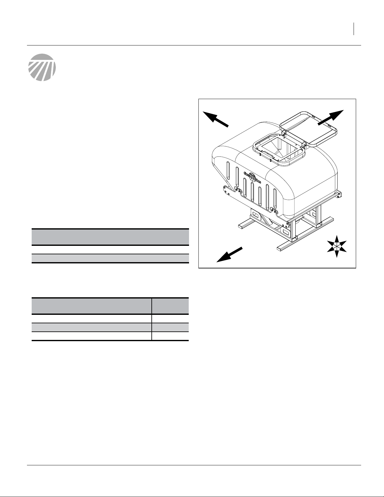
Figure 1:
403-143K Hopper
U
F
L
R
B
D
37353
12/28/2007 401-514M
Page 6
4 YP Pressure Relief Kits Great Plains Manufacturing, Inc.
Using This Manual
This manual familiarizes you with safety, assembly, operation, adjustments, troubleshooting, and maintenance.
Read this manual and follow the recommendations to
help ensure safe and efficient operation.
Call-Outs
1
11 34
to
85 89
to
Definitions
The following terms are used throughout this manual.
Note: Paragraphs in this format provide useful informa-
Paragraphs in this format present a crucial point of
information related to the current topic. Read and follow the directions to:
- remain safe,
- avoid serious damage to equipment and
- ensure desired field results.
Single-digit callouts identify components in
the currently referenced Figure or Figures.
These numbers may be reused for different
items from page to page.
Two-digit callouts in the range 11-34 reference new parts from the new parts lists
beginning on page 16. The descriptions
match those on the parts, cartons, bags or
item tags, as well as descriptions your
updated Parts Manual.
Two-digit callouts in the range 85-89 reference existing parts removed and reused.
tion related to the current topic.
IMPORTANT !
Owner Assistance
If you need customer service or repair parts, contact a
Great Plains dealer. They have trained personnel, repair
parts and equipment specially designed for Great Plains
products.
Your machine’s parts were specially designed and
should only be replaced with Great Plains parts.
Record your pressure relief kit kit model number here for
quick reference:
Model Number:__________________________
Date Purchased: __________________________
Your Great Plains dealer wants you to be satisfied with
your updated machine. If you do not understand any part
of this manual or are not satisfied with the service
received, please take the following actions.
1. Discuss the matter with your dealership service
manager. Make sure they are aware of any problems
so they can assist you.
2. If you are still unsatisfied, seek out the owner or general manager of the dealership.
For further assistance write to:
Product Support
Great Plains Mfg. Inc., Service Department
PO Box 5060
Salina, KS 67402-5060
Refer to Figure 1 on page 3
Right-hand and left-hand as
used in this manual are determined by facing the direction
the machine will travel while in
use unless otherwise stated.
An orientation rose (shown at
right) depicts Up, Right, Back,
Down, Left and Front.
401-514M 12/28/2007
U
F
L
R
B
D
785-823-3276
Page 7

Great Plains Manufacturing, Inc. Installation Instructions 5
Installation Instructions
Before You Start
Most accidents are the result of negligence and carelessness, usually caused by failure of the operator to follow simple but necessary safety precautions. Allow no
one to install the pressure relief kit before carefully reading this manual.
Some fasteners may be loosely assembled. Remove
them before mounting that component. Due to evolving
manufacturing practices, some assemblies may already
be completely pre-assembled. If so, check that fasteners
are tight, and skip the unneeded assembly steps.
Tools Required
• Basic hand tools, including a center punch and a fine
tip indelible marker
• Portable drill with a
• Twist drill bits of sizes:
Bolt hole: 0.41in,
Pilot hole: approx. 0.13in,
• Measuring square
• Silicone sealant
• Blocks of supports for hopper
• Ladder
Torque values for fasteners are shown on page 15.
1. Read and understand “Important Safety Informa-
tion” starting on page 1.
1
⁄
in (12mm) chuck
2
13
⁄
in, Z, or 10.1mm
32
1
⁄
8
in, #31, or 3.0mm
Prepare Hopper
!
WARNING
Possible Confined Space Hazard. Do not enter hopper.
The instructions in this manual do not require hopper entry.
A hopper that has been used may represent a Confined Space
Hazard, due to low oxygen, high dust and/or chemical fumes.
U
F
L
R
B
D
+
1
Refer to Figure 2
2. Empty the hopper per the clean-out instructions in
your Operator Manual. Remove the strainer basket(s) and leave the slide gate open.
3. From the walkboard (or a lift, if the hopper is dis-
mounted), thoroughly pressure wash the inside of
the hopper.
4. Allow the hopper to drain and dry.
1 2
2
Figure 2:
Prepare Hopper
12/28/2007 401-514M
27354
Page 8

6 YP Pressure Relief Kits Great Plains Manufacturing, Inc.
Dismount Hopper
U
!
CAUTION
You will be handling the bottom components of the hopper, and
any remaining moisture may contain residual seed treatments.
This update cannot be performed with a hopper cradled
on a planter, as the planter airbox obstructs access from
below. Consult the planter Operator manual for hopper
removal instructions.
5. While waiting for the hopper to dry, prepare a suitable work location. Use a level, dry, well-lighted area.
Pick a location with a clear surface beneath, so that
any dropped tools or parts can be easily located.
For work access to the bottom of the hopper, the
assembly needs to raised at least 18in (46cm). One
method, as shown in Figure 3, is to rest it on blocks
or supports under the lateral tubes of the structure.
F
L
R
B
D
!
CAUTION
Use adequate supports.
Make sure each support can safely support at least 150% its
apparent share of the weight. See step 6 for hopper weights.
Do not perform this work in high wind.
!
CAUTION
Anchor the hopper laterally.
Make sure that workers on ladders at later steps cannot push
or tip the hopper off the supports.
6. If the hopper to be updated is presently on a planter,
use a suitably rated forklift or hoist to remove the
hopper.
A 403-143K or 403-226K 82 bu hopper weighs 1200
pounds (544 kg) empty. Allow another 400 pounds
(181 kg) for two workers and tools,
for a total of 1600 pounds (726 kg).
A 403-174K 150 bu hopper weighs 1350 pounds
(612 kg) empty. Allow another 400 pounds (181 kg)
for two workers and tools,
for a total of 1750 pounds (794 kg).
7. Place the hopper in the prepared work location.
Figure 3:
Hopper on Blocks
27354
401-514M 12/28/2007
Page 9

Great Plains Manufacturing, Inc. Installation Instructions 7
Remove Old Door Slide
The single center stop bolt of the existing door slide interferes with the lower weldment installed at step 11. Your
kit includes a new door slide using two corner stop bolts.
Refer to Figure 4,
which depicts the water guard and door slide assembly
2
disassembled from the hopper. It is not necessary to
disassemble these components other than the door slide.
8. Pull the old slide door
82
403-234D BULK HOPPER UNLOAD DOOR (single stop bolt hole) halfway open, to provide access to
the nut and bolt.
9. Remove and save one each:
83
802-004C HHCS 1/4-20X3/4 GR5
87
803-088C NUT HEX LOCK 1/4-20 FLG
1
1
2
87
82
10. Remove the old slide door .
It is not reused.
82
Install Bottom Weldment
Installation of this part is the same for both 82 bu and
150 bu hoppers.
Refer to Figure 5
11. Select one new:
13
403-241H LOWER AIR PIPE SUPPORT 82 YP
Note: This part is not symmetrical, and must be installed
in the correct orientation. Inspect it and note:
The longer end of the large center tube is the top,
and points Up when installed. The holes on the
bracket bar are toward the bottom (Down).
With the top Up, the larger tube tilts Back, and the
longer ends of the bracket bars are Forward.
1
2
U
F
L
R
B
83
D
Figure 4:
Remove Old Door Slide
27376
1
U
13
2
Figure 5:
13
403-241H Lower Weldment
F
L
R
B
D
27356
12/28/2007 401-514M
Page 10

8 YP Pressure Relief Kits Great Plains Manufacturing, Inc.
Refer to Figure 6, which depicts (top to bottom):
13
the new weldment,
3
the water guard,
4
the door slide assembly with
85 89 87
,2x , forward fasteners and
86 89 87
,2x , rear fasteners.
12. Remove and save the side fasteners in the door
guide assembly. This is:
two sets forward:
85
1 802-167C HHCS 1/4-20X1 1/2 GR5
87
1 803-088C NUT HEX LOCK 1/4-20 FLG
89
2 804-007C WASHER FLAT 1/4 SAE PLT
two sets rear:
86
1 802-370C HHCS 1/4-20X1 3/4 GR5
87
1 803-088C NUT HEX LOCK 1/4-20 FLG
89
2 804-007C WASHER FLAT 1/4 SAE PLT
Note: Remove only the side fasteners, and no fasteners
on the front or rear faces of the door slide frame.
13. Orient the lower air pipe weldment as necessary
to pass it up through the door slide frame .
14. Re-orient top-Up/tilt-Back as shown, and align
the holes on the bracket bar with the holes in the
water guard and door slide frame. Hold it temporarily
with the four removed bolts ( and ).
15. Check that the correct bolts are in their proper holes
(longer bolts to Back). Remove each bolt. Place a flat
washer on it.
16. Apply silicone sealant to the washer and underside
of bolt head.
17. Re-insert bolt. Add a second washer inside
frame, and a nut . Tighten.
13
2
89
87
13
4
85 86
89
3
85
13
U
F
L
R
B
D
2
4
87
89
89
86
87
27355
29
12
Figure 6:
Lower Hopper Components
2
Install New Door Slide
Refer to Figure 7.
Note that either bolt may be used in either hole,
and either nut may be used on either bolt.
18. Select one set new:
17
802-004C HHCS 1/4-20X3/4 GR5
29
803-088C NUT HEX LOCK 1/4-20 FLG
Note that these are identical to the saved bolt and
87
nut removed in step 9.
19. Select one new:
12
403-234D BULK HOPPER UNLOAD DOOR
(new, with two stop bolt holes)
20. With the bent lip down, insert the new door slide
into the door frame about halfway.
401-514M 12/28/2007
2
83
21. Insert a
12
22. Pull the door slide fully open so that any debris
29
87
1783 17
Figure 7:
Install New Door Slide
17
83
or HHCS 1/4-20X3/4 GR5 bolt into
each stop bolt hole from below, and secure it with a
29 87
or NUT HEX LOCK 1/4-20 FLG.
12
from later steps can fall out of the hopper.
83
27377
Page 11

Great Plains Manufacturing, Inc. Installation Instructions 9
Assemble Upper Pipe Support
17
20
15
24
18
22
16
23
27357
Assembly of this part, if necessary, is the same for 82 bu
and 150 bu hoppers, up to step 30.
Refer to Figure 8
If this component
14
403-242S UPPER PIPE SUPPORT WELDMENT
appears to be pre-assembled, skip to step 29.
23. Select one each new:
16
403-408D AIR TRANSFER TUBE CAP
24
816-245C RUBBER GUARD REAR CTR.OUTER
and two sets new:
18
802-080C HHCS 7/16-14X1 GR5
20
803-015C NUT HEX 7/16-14 PLT
22
804-014C WASHER LOCK 7/16 PLT
23
804-041C WASHER FLAT 7/16 SAE PLT
24. Place the lock washers on the bolts .
25. Insert the rubber guard in the slot at the top of the
tube cap and capture it with the bolts. Secure the
bolts with flat washers and nuts .
26. Select one new:
15
403-407D BRACKET
and four sets new:
17
802-004C HHCS 1/4-20X3/4 GR5
19
803-006C NUT HEX 1/4-20 PLT
21
804-006C WASHER LOCK SPRING 1/4 PLT
27. Place the lock washers on the bolts .
16
22 18
24
23 20
21 17
19
21
U
F
L
R
B
D
Figure 8:
14
Upper Pipe Support
27
30
28. Position the bracket on the open front end of the
16
cap , with the break on top and facing the cap.
Secure with the four bolts and nuts .
29. If you are updating an 82 bu hopper, the upper support is complete and ready for installation. Skip to
step 39 on page 11.
15
15
19
31
28
Attach 150 bu Angle Brackets
Refer to Figure 9
30. Select two each:
27
802-017C HHCS 3/8-16X1 GR5
28
803-014C NUT HEX 3/8-16 PLT
30
804-013C WASHER LOCK SPRING 3/8 PLT
31
403-409D BRACKET ANGLE WITH HOLES
31. Loosely assemble the angle brackets to the cap
bracket through the center holes of the angle
brackets. Orient the angle bends to the inside.
12/28/2007 401-514M
15
31
U
F
L
R
B
D
Figure 9:
150 bu Angle Brackets
14
27358
Page 12

10 YP Pressure Relief Kits Great Plains Manufacturing, Inc.
Install 82 bu Upper Components
If you are updating a 150 bu hopper, use the instructions
at “Install 150 bu Upper Components” on page 12.
Remove Support for Drilling
Refer to Figure 10
The new upper pipe support for an 82 bu hopper mounts
on the existing strainer basket support , which nor-
mally will not already have holes for this purpose. Follow
step 32 through step 38 to prepare the support.
32. Remove and save eight sets of:
84
802-005C HHCS 1/4-20X1 GR5
89
804-007C WASHER FLAT 1/4 SAE PLT
88
803-230C NUT HEX FLANGE 1/4-20 PLT
33. Remove the:
81
403-332D HOPPER STRAINER BASKET SUP-
PORT
Note: The support has a notch , which must be on
81 1
the latch side of the hopper opening. The latch is:
on the left for a 403-143K 82bu hopper,
on the right for a 403-226K 82 bu hopper, and:
toward the center for a 403-174K 150bu hopper.
81
U
F
L
R
B
84
89
D
81
1
Figure 10:
Remove Strainer Support
88
27382
Mark Holes and Drill
34. Mark holes on the back span of strainer support
at the following dimensions:
Latch-side edge to latch-side hole:
A
8.25in, 8
Latch-side hole to hinge-side hole:
B
9.00in, 22.86cm
Rear edge to hole center-line
C
1.00in, 2.54cm
Hole diameter is:
H
0.41in,
Alternate reference dimensions:
D
17.25in, 17
E
1.81in, 1
F
0.81in,
35. Check hole marking with (not shown):
15
403-407D BRACKET (part of upper support )
36. Drill pilot holes, then final holes.
1
⁄
in, 20.96cm
4
13
⁄
in, 10.4mm
32
1
⁄
in, 43.82cm (L. edge to L. hole)
4
13
⁄
in, 4.60cm (back span width)
16
13
⁄
in, 2.06cm (inside to hole c/l)
16
14
81
F
Latch
Hinge
B
H
F
E
C
A
D
Figure 11:
Strainer Support Holes
B
27381
81
401-514M 12/28/2007
Page 13

Great Plains Manufacturing, Inc. Installation Instructions 11
Re-Install Strainer Support
Refer to Figure 12 (which depicts a 403-143K hopper)
37. Select the eight sets of saved:
84
802-005C HHCS 1/4-20X1 GR5
89
804-007C WASHER FLAT 1/4 SAE PLT
88
803-230C NUT HEX FLANGE 1/4-20 PLT
38. Position the drilled strainer support with the notch
to the hopper latch side and the new holes to the
rear. Place a washer on each bolt . Insert bolt
from above and secure with nut .
89 84
81
88
Position Air Pipe
39. With the upper pipe support at hand,
select one new:
25
403-403D 82 BU AIR PRESSURE PIPE
and two sets of:
27
802-017C HHCS 3/8-16X1 GR5
30
804-013C WASHER LOCK SPRING 3/8 PLT
28
803-014C NUT HEX 3/8-16 PLT
40. Insert the pipe into the hopper and slide it over the
lower pipe support weldment. Temporarily lean it
against the back of the hopper.
14
U
F
L
R
B
81
D
25
13
Figure 12:
Insert 82 bu Pipe
27363
Install Upper Pipe Support
Refer to Figure 13
41. With the bolts at hand,
swing the pipe back into the opening,
place the upper support on the pipe, with the
bracket forward.
42. Swing the pipe and support to the back of the hopper, so that the bracket edge is under the rear span
of strainer support .
43. Align the holes in the two brackets and secure them
with the bolts , washers and nuts .
44. Skip to “Closeout” on page 14.
27
25
14
81
27 30 28
U
F
R
14
L
B
D
27
30
81
28
25
Figure 13:
Install Upper 82 bu Support
12/28/2007 401-514M
27365
Page 14

12 YP Pressure Relief Kits Great Plains Manufacturing, Inc.
Install 150 bu Upper Components
If you are updating an 82bu hopper, use the instructions
at “Install 82 bu Upper Components” on page 10.
Refer to Figure 14
In the 150 bu hopper, the upper tube support mounts to
the stiffener rib molded into the hopper. Four holes, two
each side, need to be drilled.
This work is most easily accomplished from the walkboard, while the hopper is on the planter.
Refer to Figure 15,
which depicts a view fromthe right side above a view from
31
14
Figure 14:
150 bu Hopper Drill Region
27359
the rear. The eventual location of top tube support is
shown in dotted line, and the angle bracket shown in
dashed line.
Hole locations are in the side walls of the center stiffener
rib. Measurements are referenced from:
1
front face, rear lip of tank top openings
2
underside of center stiffener rib
After installation, the bottom edge of the angle bracket
31
is flush with the underside of the center stiffener rib.
Mark Holes for Drilling
45. Holes are above the underside of center stiffener rib:
A
2.28in, 2
46. The rear holes are located forward of the lip at:
B
7.02in, 7
47. The front holes are forward of the rear holes by:
C
5.50in, 5
For reference, the total distance from the lip to the
forward holes is:
E
12.52in, 12
48. Mark the hole centers. Hole diameter is:
H
0.41in,
49. Use a 16in (41cm) straight edge to mark a line
between the hole centers, and about 2in (5cm) on
either side.
Note: Depending on the hopper and part tolerances,
these may not be the final hole positions. The final
holes are marked and drilled beginning at step 53.
9
⁄
in, 5.79cm
32
1
⁄
in, 17.82cm
64
1
⁄
in, 13.97cm
2
33
⁄
64
13
⁄
in, 10.4mm
32
in, 31.79cm
B
U
D
E
F
B
C
1
H
31
A
14
2
Figure 15: Side / Rear View
27360
150 bu Drill Holes
401-514M 12/28/2007
Page 15

Great Plains Manufacturing, Inc. Installation Instructions 13
Insert Pipe in Hopper
Refer to Figure 16
50. Select one new:
32
403-427D 150 BU AIR PRESSURE PIPE
51. Insert the pipe into the hopper and slide it over
the lower pipe support weldment. Have a second
worker hold it, or temporarily lean it against the back
of the hopper.
32
Cap and Position Pipe
52. Select the:
14
403-242S UPPER PIPE SUPPORT WELDMENT
with the angle brackets loosely attached.
Refer to Figure 17
53. Place the cap assembly on top of the pipe and
maneuver it so that the four holes in the angle brack-
31
ets align with the marks for the holes to be drilled.
It may be necessary to temporarily remove one
angle bracket in some cases.
If all four holes cannot be aligned, align to the forward holes. If both left and right side forward holes
cannot be aligned, use the left forward hole.
54. Make sure the angle bracket bolts are finger tight,
and make final marks for drilling. Fore-and-aft location of the holes is not critical, but if a hole needs to
be re-marked, make sure the vertical position is on
the centerline marked at step 49.
31
14 32
U
D
R
B
32
F
L
13
Figure 16:
Insert 150 bu Pipe
27364
Drill 150 bu Holes
These holes need to be drilled from the inside, as the
exterior channel of the stiffener rib is not wide enough for
most portable drills.
55. Swing the pipe assembly clear.
56. Drill pilot holes. Re-check hole placement and drill
final holes.
57. Sweep out any drill swarf that might eventually clog a
seed meter.
IMPORTANT !
If any error is made in hole drilling, close the hole with
5
a
⁄
in or 8mm bolt, washers and nut, coated with
16
silicone sealant. A hole left open adversely affects
seed delivery.
12/28/2007 401-514M
32
Figure 17:
Position 150 bu Pipe
31
14
27366
Page 16

14 YP Pressure Relief Kits Great Plains Manufacturing, Inc.
Attach Upper 150 bu Support
Refer to Figure 18
58. Select four sets of new:
33
802-079C HHCS 3/8-16X1 1/4 GR5
34
803-209C NUT FLANGE LOCK 3/8-16 PLT
31
59. Loosen the bolts holding the angle brackets, and
apply silicone sealant around the holes in the hopper. Re-position the angle brackets at the holes and
loosely re-tighten bolts .
60. Apply silicone sealant to the underside of bolt heads
33
, and insert them. from the inside of the hopper,
through the angle brackets and hopper. Secure with
flange lock nuts .
61. When all four flange lock nuts are tight, tighten
27
bolts .
27
27
34
34
Closeout
62. Re-install strainer(s).
63. Close lid(s).
64. Close door slide.
65. Re-mount hopper on planter (if next use will rely on
hopper rather than bulk seed box).
66. Obtain an updated Operator Manual for your planter.
Review sections on fan and hopper operations, as
recommended fan speeds are higher for updated
hoppers.
27
34
Figure 18:
Attach 150 bu Upper Support
33
27367
401-514M 12/28/2007
Page 17

Great Plains Manufacturing, Inc. Appendix 15
Appendix
Torque Values
Bolt
Size
in-tpi
1
⁄4-20
1
⁄4-28
5
⁄16-18
5
⁄16-24
3
⁄8-16
3
⁄8-24
7
⁄16-14
7
⁄16-20
1
⁄2-13
1
⁄2-20
9
⁄16-12
9
⁄16-18
5
⁄8-11
5
⁄8-18
3
⁄4-10
3
⁄4-16
7
⁄8-9
7
⁄8-14
1-8
1-12
11⁄8-7
11⁄8-12
11⁄4-7
11⁄4-12
13⁄8-6
13⁄8-12
11⁄2-6
11⁄2-12
Bolt Head Identification
Bolt Head Identification
Bolt
Size
Grade 2 Grade 5 Grade 8 Class 5.8 Class 8.8 Class 10.9
1
N-m2ft-lb
7.4 5.6 11 8 16 12
8.5 6 13 10 18 14
15 11 24 17 33 25
17 13 26 19 37 27
27 20 42 31 59 44
31 22 47 35 67 49
43 32 67 49 95 70
49 36 75 55 105 78
66 49 105 76 145 105
75 55 115 85 165 120
95 70 150 110 210 155
105 79 165 120 235 170
130 97 205 150 285 210
150 110 230 170 325 240
235 170 360 265 510 375
260 190 405 295 570 420
225 165 585 430 820 605
250 185 640 475 905 670
340 250 875 645 1230 910
370 275 955 705 1350 995
480 355 1080 795 1750 1290
540 395 1210 890 1960 1440
680 500 1520 1120 2460 1820
750 555 1680 1240 2730 2010
890 655 1990 1470 3230 2380
1010 745 2270 1670 3680 2710
1180 870 2640 1950 4290 3160
1330 980 2970 2190 4820 3560
Torque tolerance + 0%, -15% of torquing values. Unless otherwise specified use torque values listed above.
3
N-m ft-lb N-m ft-lb
mm x pitch
4
M 5 X 0.8
M 6 X 1
M 8 X 1.25
M 8 X 1
M10 X 1.5
M10 X 0.75
M12 X 1.75
M12 X 1.5
M12 X 1
M14 X 2
M14 X 1.5
M16 X 2
M16 X 1.5
M18 X 2.5
M18 X 1.5
M20 X 2.5
M20 X 1.5
M24 X 3
M24 X 2
M30 X 3.5
M30 X 2
M36 X 3.5
M36 X 2
1. in-tpi = nominal thread diameter in inches-threads per inch
2. N· m = newton-meters
3. ft-lb = foot pounds
4. mm x pitch = nominal thread diameter in millimeters x thread
pitch
5.8 8.8 10.9
N-m ft-lb N-m ft-lb N-m ft-lb
43659 7
7 5 11 8 15 11
17 12 26 19 36 27
18 13 28 21 39 29
33 24 52 39 72 53
39 29 61 45 85 62
58 42 91 67 125 93
60 44 95 70 130 97
90 66 105 77 145 105
92 68 145 105 200 150
99 73 155 115 215 160
145 105 225 165 315 230
155 115 240 180 335 245
195 145 310 230 405 300
220 165 350 260 485 355
280 205 440 325 610 450
310 230 650 480 900 665
480 355 760 560 1050 780
525 390 830 610 1150 845
960 705 1510 1120 2100 1550
1060 785 1680 1240 2320 1710
1730 1270 2650 1950 3660 2700
1880 1380 2960 2190 4100 3220
12/28/2007 401-514M
Page 18

16 YP Pressure Relief Kits Great Plains Manufacturing, Inc.
Parts Lists
401-508A 82 bu Pressure Release Kit
19
27
24
30
14
{
28 18
15
25
21
17
23
22
20
16
13
12
29
401-508A YP 82 BU AIR RELEASE FLD KIT
401-514M 12/28/2007
17
27350
Page 19

Great Plains Manufacturing, Inc. Appendix 17
401-508A Part Numbers
Callout Part Number Quantity Part Description
11
12
13
14
15
16
17
18
19
20
21
22
23
24
25
26
27
28
29
30
401-514M 1
403-234D 1
403-241H 1
403-242S 1
403-407D 1
403-408D 1
802-004C 4
802-080C 2
803-006C 4
803-015C 2
804-006C 4
804-014C 2
804-041C 2
816-245C 1
403-403D 1
802-004C 1
802-017C 2
803-014C 1
803-088C 1
804-013C 2
MANUAL 82 & 150 BU AIR KIT (This manual. Not shown.)
BULK HOPPER UNLOAD DOOR (new, with two stop bolt holes)
LOWER AIR PIPE SUPPORT 82 YP
UPPER PIPE SUPPORT WELDMENT
BRACKET
AIR TRANSFER TUBE CAP
HHCS 1/4-20X3/4 GR5
HHCS 7/16-14X1 GR5
NUT HEX 1/4-20 PLT
NUT HEX 7/16-14 PLT
WASHER LOCK SPRING 1/4 PLT
WASHER LOCK 7/16 PLT
WASHER FLAT 7/16 SAE PLT
RUBBER GUARD REAR CTR.OUTER
82 BU AIR PRESSURE PIPE
HHCS 1/4-20X3/4 GR5
HHCS 3/8-16X1 GR5
NUT HEX 3/8-16 PLT
NUT HEX LOCK 1/4-20 FLG
WASHER LOCK SPRING 3/8 PLT
12/28/2007 401-514M
Page 20

18 YP Pressure Relief Kits Great Plains Manufacturing, Inc.
401-516A 150 bu Pressure Release Kit
27
34
19
14
15
{
32
21
17
30
33
31
28
24
18
23
22
20
16
13
12
29
401-516A YP 150 BU AIR RELEASE FLD KIT
401-514M 12/28/2007
17
27351
Page 21

Great Plains Manufacturing, Inc. Appendix 19
401-516A Part Numbers
Callout Part Number Quantity Part Description
11
12
13
13
15
16
17
18
19
20
21
22
23
24
17
27
28
29
30
31
32
33
34
401-514M 1
403-234D 1
403-241H 1
403-242S 1
403-407D 1
403-408D 1
802-004C 4
802-080C 2
803-006C 4
803-015C 2
804-006C 4
804-014C 2
804-041C 2
816-245C 1
802-004C 1
802-017C 2
803-014C 2
803-088C 2
804-013C 2
403-409D 2
403-427D 1
802-079C 4
803-209C 4
MANUAL 82 & 150 BU AIR KIT (This manual. Not shown.)
BULK HOPPER UNLOAD DOOR (new, with two stop bolt holes)
LOWER AIR PIPE SUPPORT 82 YP
UPPER PIPE SUPPORT WELDMENT
BRACKET
AIR TRANSFER TUBE CAP
HHCS 1/4-20X3/4 GR5
HHCS 7/16-14X1 GR5
NUT HEX 1/4-20 PLT
NUT HEX 7/16-14 PLT
WASHER LOCK SPRING 1/4 PLT
WASHER LOCK 7/16 PLT
WASHER FLAT 7/16 SAE PLT
RUBBER GUARD REAR CTR.OUTER
HHCS 1/4-20X3/4 GR5
HHCS 3/8-16X1 GR5
NUT HEX 3/8-16 PLT
NUT HEX LOCK 1/4-20 FLG
WASHER LOCK SPRING 3/8 PLT
BRACKET ANGLE WITH HOLES
150 BU AIR PRESSURE PIPE
HHCS 3/8-16X1 1/4 GR5
NUT FLANGE LOCK 3/8-16 PLT
Existing Parts Affected
Callout Part Number Description Disposition
81
82
83
84
85
86
87
88
89
12/28/2007 401-514M
403-332D
403-234D
802-004C
802-005C
802-167C
802-370C
803-088C
803-230C
804-007C
HOPPER STRAINER BASKET SUPPORT Removed, modified and re-installed.
BULK HOPPER UNLOAD DOOR (single
stop bolt hole)
Removed.
Not re-used.
HHCS 1/4-20X3/4 GR5 Removed and re-installed.
HHCS 1/4-20X1 GR5 Removed and re-installed.
HHCS 1/4-20X1 1/2 GR5 Removed and re-installed.
HHCS 1/4-20X1 3/4 GR5 Removed and re-installed.
NUT HEX LOCK 1/4-20 FLG Removed and re-installed.
NUT HEX FLANGE 1/4-20 PLT Removed and re-installed.
WASHER FLAT 1/4 SAE PLT Removed and re-installed.
Page 22

20 YP Pressure Relief Kits
Great Plains Manufacturing, Inc.
Great Plains Manufacturing, Inc.
Corporate Office: P.O. Box 5060
Salina, Kansas 67402-5060 USA
401-514M 12/28/2007
 Loading...