

Page 1

Operator’s Manual
Series I 1000TT, 1200TT, 1700TT, 2200TT, 3000TT & 4000TT
!
(S/N K1001NN to GP-2758NN)
Read the operator’s manual entirely. When you see this symbol, the subsequent
instructions and warnings are serious - follow without exception. Your life and the
lives of others depend on it
Turbo-Till
Cover illustration may show optional equipment not supplied with standard unit.
©Copyright 2003 Printed 1/25/2008 586-043M
Page 2

Great Plains Mfg., Inc. First Page ► Table of Contents
Table of Contents
Important Safety Information .......................... 1
Safety Rules................................................... 6
Safety Decals ................................................ 7
Introduction ........................................................ 12
Description of Unit........................................ 12
Using this Manual ........................................12
Definitions.............................................. 12
Owner Assistance .......................................... 12
Assembly and Setup Assistance .................... 13
Product Support .....................................13
Pre-Assembly Checklist ........................ 13
Section 1 Assembly ............................................. 14
Center Frame, Torque Tube & Gang Bar
Assembly ................................................. 14
Center Wing Stop, Fold Brackets & Lift
Assembly ................................................. 15
Hitch & Self Level Assembly ...................... 16
Wing and Wheel Arm Assembly .................. 17
Wing Lift Assembly ..................................... 18
1700TTX* Wing Assembly ......................... 19
40’ Wing Fold Strap & Fold Bracket Assy. .. 20
40’ Outside Wing Assembly ........................21
Hydraulic Valve Mounting Assembly .......... 22
Hydraulic Cylinder Purging Procedure ........ 23
Turbo Gang Placement ................................. 24
Completing Setup ......................................... 29
Section 2 Hydraulics .......................................... 30
Hydraulic Lift System:
1000TT, 1200TT & 1700TT .................... 30
2200TT, 3000TT & 4000TT .................... 32
Hydraulic Fold System:
1700TT, 2200TT & 3000TT .................... 34
4000TT .................................................... 36
Hydraulic Hose Layouts:
1000TT & 1200TT .................................. 38
1700TT .................................................... 39
© Copyright 2003 All rights Reserved
Great Plains Manufacturing, Inc. provides this publication “as is” without warranty of any kind, either expressed or implied. While every precaution has been taken in the
preparation of this manual, Great Plains Manufacturing, Inc. assumes no responsibility for errors or omissions. Neither is any liability assumed for damages resulting from the
use of the information contained herein. Great Plains Manufacturing, Inc. reserves the right to revise and improve its products as it sees fit. This publication describes the state
of this product at the time of its publication, and may not reflect the product in the future.
The following are trademarks of Great Plains Mfg., Inc.: Application Systems, Ausherman, Land Pride, Great Plains
All other brands and product names are trademarks or registered trademarks of their respective holders.
Great Plains Manufacturing, Incorporated Trademarks
Printed in the United States of America.
2200TT .................................................... 40
3000TT .................................................... 41
4000TT .................................................... 42
17’, 22’ & 30’ Hydraulic Down Pressure
Preparation and Setup ............................ 44
40’ Hydraulic Down Pressure
Preparation and Setup ............................. 45
Section 3 Replacement Parts ............................ 46
1000TT Center Transport Assembly............. 46
1200TT, 1700TT & 2200TT Center
Transport Assembly ................................. 48
3000TT Center Transport & 4000TT
Wing Transport Assembly ...................... 50
4000TT Center Transport Assembly............. 52
2200TT Wing Transport Assembly ............. 54
3000TT Wing Transport Assembly ............. 56
Turbo Gang Assembly ................................. 58
Heavy Turbo Gang Assembly ...................... 60
Section 4 Machine Layout ................................. 62
1000TT Machine Layout, 10” ...................... 62
1200TT Machine Layout, 10” ...................... 63
1700TT Machine Layout, 10” ...................... 64
2200TT Machine Layout, 10” ...................... 65
3000TT Machine Layout, 10” ...................... 66
4000TT Machine Layout, 10” ...................... 67
Section 5 Operating and Maintenance.............. 68
Prior to Going to the Field ........................... 68
General Operating Instructions and
In-Field Adjustments .................................... 69
Maintenance and Lubrication ....................... 71
Section 6 Specification and Capacities ............. 72
Appendix ............................................................. 73
Torque Values for Common Bolt Sizes ....... 73
Tire Inflation Chart ...................................... 73
Warranty ....................................................... 74
2/09/2006 Series I 1000TT - 4000TT Turbo-Till 586-043M
* Model 1700TTX is 5 meter foreign export model, not sold in USA.
Page 3
Great Plains Mfg., Inc. Table of Contents ► Important Safety Information
R
Important Safety Information
Look for Safety Symbol
The SAFETY ALERT SYMBOL indicates there is
a potential hazard to personal safety involved
and extra safety precaution must be taken.
When you see this symbol, be alert and carefully
read the message that follows it. In addition to
design and configuration of equipment, hazard
control and accident prevention are dependent
upon the awareness, concern, prudence and
proper training of personnel involved in the
operation, transport, maintenance and storage of
equipment.
Be Aware of Signal Words
!
Signal words designate a degree or level of hazard seriousness.
DANGER indicates an imminently hazardous situation, which, if not avoided, will result in death
or serious injury. This signal word is limited to
the most extreme situations, typically for
machine components that, for functional
purposes, cannot be guarded.
WARNING indicates a potentially hazardous
situation, which, if not avoided, could result in
death or serious injury, and includes hazards
that are exposed when guards are removed. It
may also be used to alert against unsafe
practices.
CAUTION indicates a potentially hazardous situation, which, if not avoided, may result in minor
or moderate injury. It may also be used to alert
against unsafe practices.
!
DANGE
!
WARNING
!
CAUTION
12/15/2004 Series I 1000TT- 4000TT Turbo-Till 586-043M
1
Page 4
Important Safety Information Table of Contents ► Great Plains Mfg., Inc.
Be Familiar with Safety Decals
• Read and understand “Safety Decals,” page
7, thoroughly.
• Read all instructions noted on the decals.
Keep Riders Off Machinery
• Riders obstruct the operator’s view. Riders
could be struck by foreign objects or thrown
from the machine.
• Never allow children to operate equipment.
• Keep all bystanders away from machine dur-
ing operation.
Shutdown and Storage
• Lower Series I Turbo Till, put tractor in park,
turn off engine, and remove the key.
• Secure Series I Turbo Till using blocks and
supports provided.
• Detach and store Series I Turbo Till in an
area where children normally do not play.
Use Safety Lights and Devices
• Slow-moving tractors and towed implements
can create a hazard when driven on public
roads. They are difficult to see, especially at
night.
• Use flashing warning lights and turn signals
whenever driving on public roads.
• Use lights and devices provided with implement.
OFF
Series I 1000TT- 4000TT Turbo-Till 586-043M 12/15/2004
2
Page 5
Great Plains Mfg., Inc. Table of Contents ► Important Safety Information
Transport Machinery Safely
Maximum transport speed for implement is 20
mph. Some rough terrains require a slower
speed. Sudden braking can cause a towed load
to swerve and upset.
• Do not exceed 20 mph. Never travel at a
speed which does not allow adequate
control of steering and stopping. Reduce
speed if towed load is not equipped with
brakes.
• Comply with state and local laws.
• Do not tow an implement that, when fully
loaded, weighs more than 1.5 times the
weight of towing vehicle.
• Carry reflectors or flags to mark tractor and
implement in case of breakdown on the
road.
• Keep clear of overhead power lines and
other obstructions when transporting. Refer
to transport dimensions under
“Specifications and Capacities,” page 72.
• Do not fold or unfold the wings while the
tractor is moving.
Avoid High Pressure Fluids
Escaping fluid under pressure can penetrate the
skin, causing serious injury.
• Avoid the hazard by relieving pressure
before disconnecting hydraulic lines.
• Use a piece of paper or cardboard, NOT
BODY PARTS, to check for suspected
leaks.
• Wear protective gloves and safety glasses
or goggles when working with hydraulic
systems.
• If an accident occurs, see a doctor immediately. Any fluid injected into the skin must be
surgically removed within a few hours or
gangrene may result.
12/15/2004 Series I 1000TT- 4000TT Turbo-Till 586-043M
3
Page 6
Important Safety Information Table of Contents ► Great Plains Mfg., Inc.
Practice Safe Maintenance
• Understand procedure before doing work.
Use proper tools and equipment. Refer to
this manual for additional information.
• Work in a clean, dry area.
• Lower the Series I Turbo Till, put tractor in
park, turn off engine, and remove key before
performing maintenance.
• Make sure all moving parts have stopped
and all system pressure is relieved.
• Inspect all parts. Make sure parts are in
good condition and installed properly.
• Remove buildup of grease, oil or debris.
• Remove all tools and unused parts from
Series I Turbo Till before operation.
Prepare for Emergencies
• Be prepared if a fire starts.
• Keep a first aid kit and fire extinguisher
handy.
• Keep emergency numbers for doctor, ambulance, hospital and fire department near
phone.
Wear Protective Equipment
• Wear protective clothing and equipment.
• Wear clothing and equipment appropriate for
the job. Avoid loose-fitting clothing.
• Because prolonged exposure to loud noise
can cause hearing impairment or hearing
loss, wear suitable hearing protection such
as earmuffs or earplugs.
• Because operating equipment safely
requires your full attention, avoid wearing
radio headphones while operating
machinery.
911
Series I 1000TT- 4000TT Turbo-Till 586-043M 12/15/2004
4
Page 7
Great Plains Mfg., Inc. Table of Contents ► Important Safety Information
Handle Chemicals Properly
• Agricultural chemicals can be dangerous.
Improper use can seriously injure persons,
animals, plants, soil and property.
• Read and follow chemical manufacturer’s
instructions.
• Wear protective clothing.
• Handle all chemicals with care.
• Avoid inhaling smoke from any type of
chemical fire.
• Store or dispose of unused chemicals as
specified by chemical manufacturer.
Use A Safety Chain
• Use a safety chain to help control drawn
machinery should it separate from tractor
drawbar.
• Use a chain with a strength rating equal to or
greater than the gross weight of towed
machinery.
• Attach chain to tractor drawbar support or
other specified anchor location. Allow only
enough slack in chain to permit turning.
• Replace chain if any links or end fittings are
broken, stretched or damaged.
• Do not use safety chain for towing.
Tire Safety
• Tire changing can be dangerous and should
be performed by trained personnel using
correct tools and equipment.
• When inflating tires, use a clip-on chuck and
extension hose long enough to you to stand
to one side–not in front of or over tire
assembly. Use a safety cage if available.
• When removing and installing wheels, use
wheel-handling equipment adequate for
weight involved.
12/15/2004 Series I 1000TT- 4000TT Turbo-Till 586-043M
5
Page 8

Important Safety Information Table of Contents ► Great Plains Mfg., Inc.
Safety Rules
• Thoroughly read and understand the
instructions in this manual before operation.
Read all instructions noted on the safety
decals.
• Be familiar with all Series I Turbo Till
functions.
• Operate machinery from the driver’s seat
only.
• Do not leave Series I Turbo Till unattended
with tractor engine running.
• Do not transport Series I Turbo Till
the transport pins and all wing locks are
installed.
• Limit transport speed to 20 m.p.h.
• Know the transport height of your unit and be
extremely careful of overhead electrical and
telephone lines when transporting the unit.
• Know the transport width of your machine and
the width of bridges, etc… on the transport
route.
• Make sure that no one is near the machine
during field operation and folding or unfolding
of wing sections.
• Prior to removing any lift cylinders from the
machine, lower implement to the ground, shut
off the tractor and release the pressure in the
lines.
• Do not depend on cylinders to hold the weight
of machine during storage; use the transport
locks.
• Do not walk or stand on any part of the
machine. Never allow anyone to ride on the
Series I Turbo Till.
• Use extreme care when hitching or unhitching
the machine from the tractor. In some
situations with a heavy finishing attachment,
the machine may tip backward causing the
hitch to rise rapidly.
• Never stand with feet under any part of the
machine.
until
• Never allow anyone to walk between the
tractor and Series I Turbo Till while machine is
in operation.
• Keep hands and feet away from turbo blades.
They are quite sharp.
• Any moving piece of equipment is potentially
dangerous. Do not operate until you are
absolutely sure the area is clear of children,
pets and irresponsible persons.
• Escaping hydraulic fluid under pressure can
have sufficient force to penetrate the skin,
causing serious injury. To prevent injury
when working with hydraulics, follow the
instructions on page 3.
• Before transporting the unit on public roads,
check to make sure the safety reflectors are
clean and visible, and not missing or
damaged. Turn on tractor warning lights
when transporting.
• Make sure all safety signs are clean, readable
and not damaged. Contact Great Plains Mfg.
for free replacements if necessary.
Series I 1000TT- 4000TT Turbo-Till 586-043M 12/15/2004
6
Page 9
Great Plains Mfg., Inc. Table of Contents ► Important Safety Information
Safety Decals
Your implement comes equipped with all safety
decals in place. They were designed to help you
safely operate your implement.
• Read and follow decal directions.
• Keep all safety decals clean and legible.
• Replace all damaged or missing decals. Orde r
new decals from your Great Plains dealer.
Refer to this section for proper placement.
• When ordering new parts or components, also
request corresponding safety decals.
• To install new decals:
1. Clean the area on which the decal is to be
placed.
2. Peel backing from decal. Press firmly on
surface, being careful not to cause air
bubbles under decal.
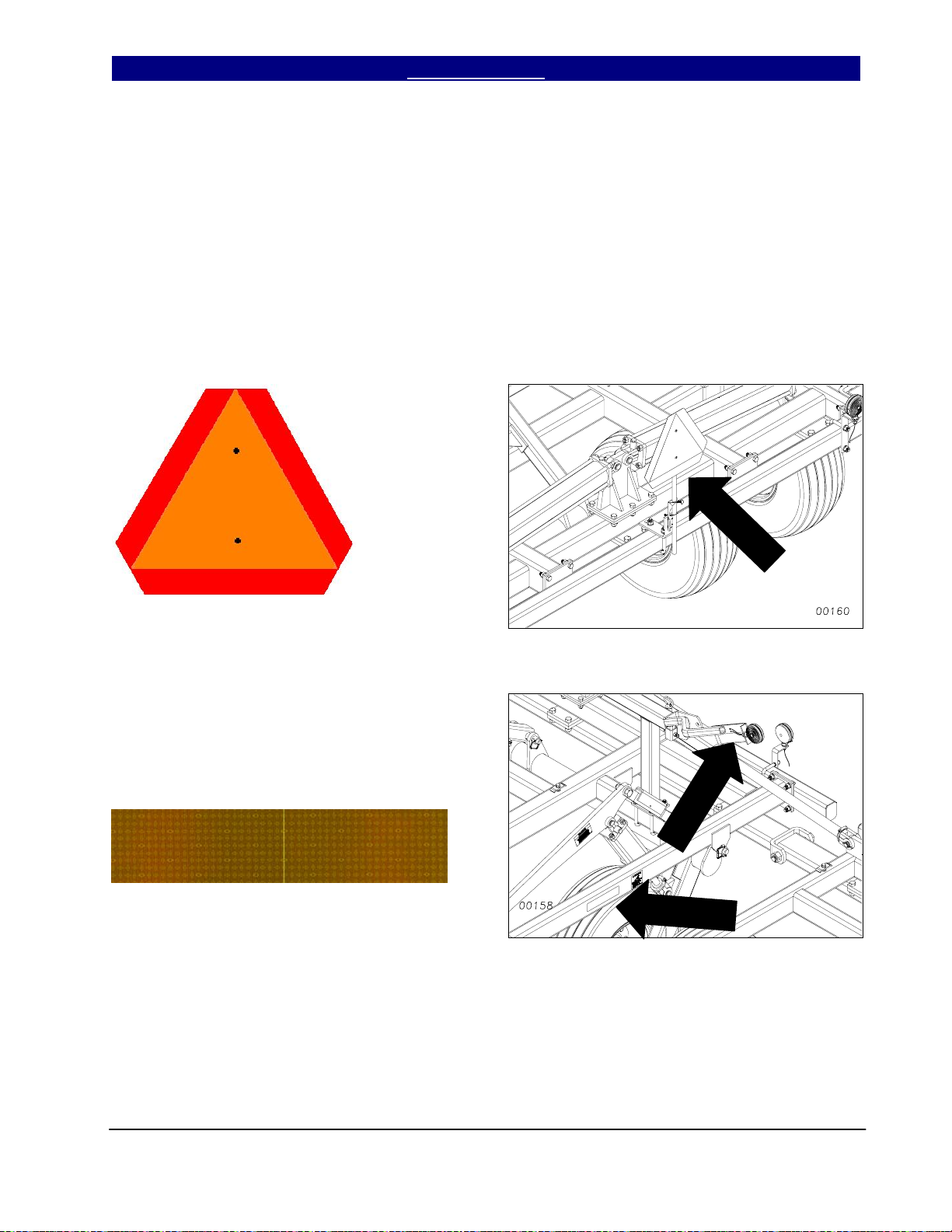
Slow Moving Vehicle Emblem
See Parts Manual 586-043P
Quantity 1
Reflector – Amber
838-615C
Quantity 6: Two on light bracket and two on
center frame. Two on rear of finishing
attachment (not shown), visible from side
while folded for transport.
Quantity 4: 1000TT & 1200TT
3/21/2005 Series I 1000TT- 4000TT Turbo-Till 586-043M
7
Page 10
Important Safety Information Table of Contents ► Great Plains Mfg., Inc.
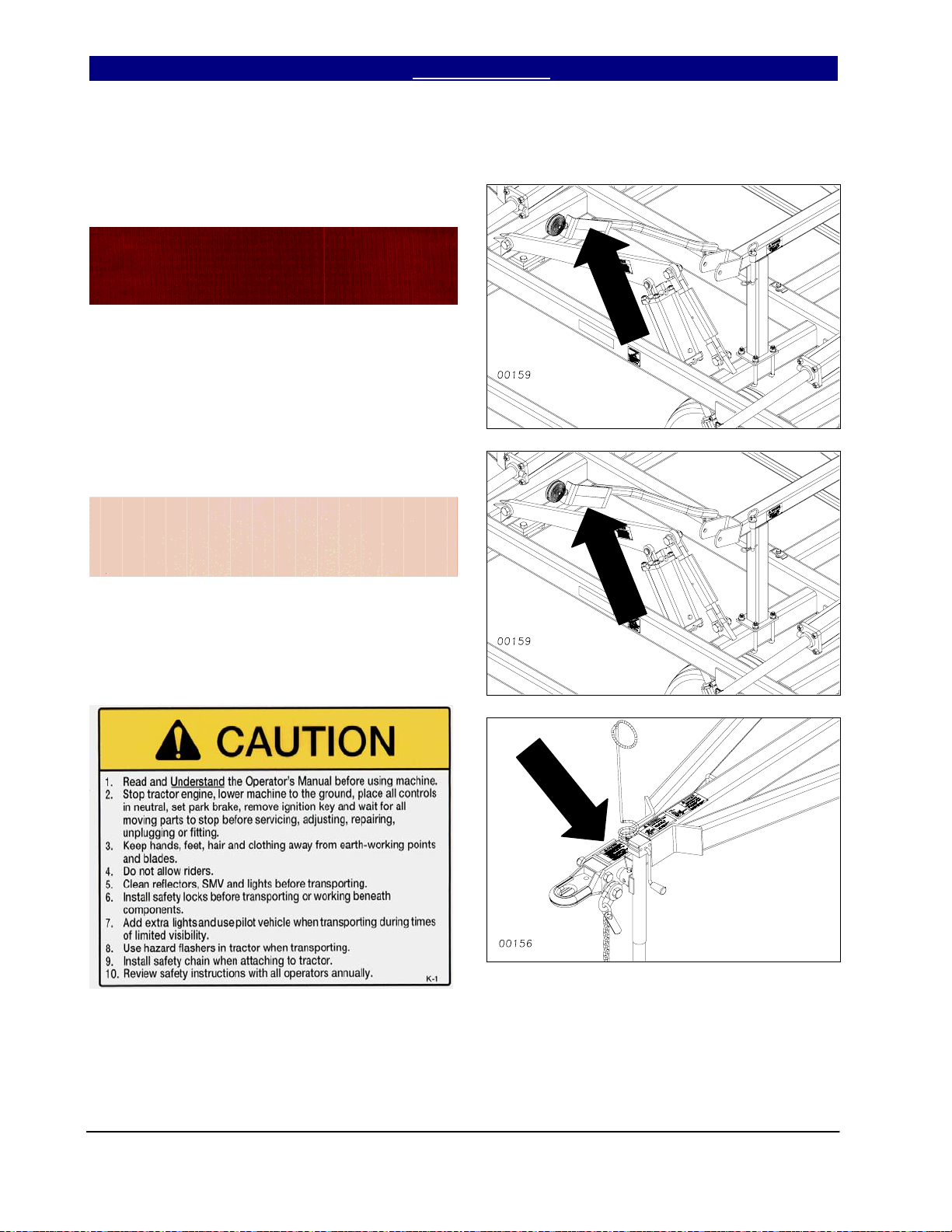
Reflector – Red
838-614C
Quantity 2:
Reflector – Florescent Orange
838-603C
Quantity 2:
Caution
838-598C
Quantity 1
Series I 1000TT- 4000TT Turbo-Till 586-043M 3/21/2005
8
Page 11
Great Plains Mfg., Inc. Table of Contents ► Important Safety Information
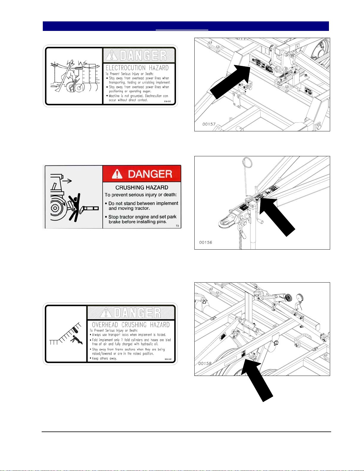
Danger Electrocution Hazard
818-818C
Quantity 1
Danger Crushing Hazard
838-600C
Quantity 1
Warning Overhead Wing Hazard
818-046C
Quantity 2: 1700TT, 2200TT, 3000TT &
4000TT
3/21/2005 Series I 1000TT- 4000TT Turbo-Till 586-043M
9
Page 12
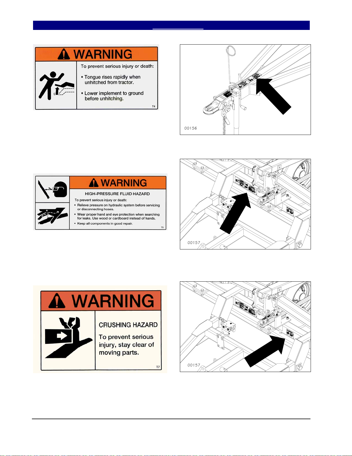
Important Safety Information Table of Contents ► Great Plains Mfg., Inc.
Warning Tongue Rising
838-606C
Quantity 1
Warning High Pressure Fluid Hazard
838-094C
Quantity 1
Warning Crushing Hazard
838-611C
Quantity 1
Series I 1000TT- 4000TT Turbo-Till 586-043M 3/21/2005
10
Page 13
Great Plains Mfg., Inc. Table of Contents ► Important Safety Information
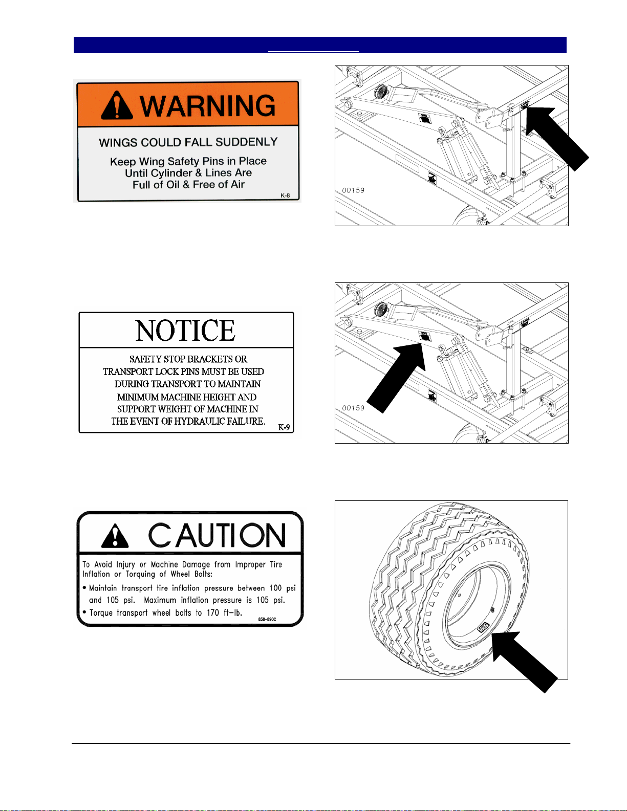
Warning Wing Falling Hazard
838-612C
Quantity 2 1700TT, 2200TT, 3000TT &
4000TT
Notice
838-613C
Quantity 2
Caution Tire Inflation for Galaxy Tires
838-890C
Quantity 4
3/21/2005 Series I 1000TT- 4000TT Turbo-Till 586-043M
3/29/2007
11
Page 14

Introduction Table of Contents ► Great Plains Mfg., Inc.
Introduction
Great Plains welcomes you to its growing family of
new product owners. This implement has been
designed with care and built by skilled workers
using quality materials. Proper assembly,
maintenance and safe operation will help you get
years of satisfactory machine use from your
machine. To ease the assembly task and produce
a properly working machine, read this entire
manual before assembling or setting up new
equipment.
Description of Unit
The Series I 1000TT - 4000TT Turbo Till is a one,
three or five-section “vertical” tillage tool. Working
width ranges from 10 to 40 feet. The implement is
designed to cut and size residue, till soil for faster
seedbed warming, break up soil crust on hard
dried fields while eliminating compaction layers.
Various finishing attachments are available to
further smooth, redistribute residue, kill weeds,
and break clods.
Using This Manual
This manual will familiarize you with safety,
assembly, operation, adjustment, troubleshooting
and maintenance. Read this manual and follow
the recommendations to help ensure safe and
efficient operation.
The information in this manual is current at printing. Some parts may change to assure top
performance.
Definitions
The following terms are used throughout this
manual.
Right and left as used in this manual are deter-
mined by facing the direction the machine will
travel while in use unless otherwise stated.
IMPORTANT: A crucial point of information
about the preceding topic. For safe and correct
operation, read and follow the directions provided
before continuing.
NOTE: Useful information about the preceding
topic.
Owner Assistance
If customer service or repairs are needed, contact
your Great Plains dealer. They have trained
personnel, parts and service equipment specially
designed for Great Plains products.
Your machine’s parts should only be replaced with
Great Plains parts. Always use the serial and
model number when ordering parts from your
Great Plains dealer. The serial-number plate is
on the center section of the implement on the front
frame tube.
Record your implement model and serial numbers
here for quick reference.
Model Number: __________________________
Serial Number: ___________________________
Your Great Plains dealer wants you to be satisfied
with your new machine. If you do not understand
any part of this manual or are not satisfied with
the service received, please take the following
actions:
1. Discuss the matter with your dealer’s service
manager. Make sure they are aware of any
problems so they can assist you.
2. If you are still not satisfied, seek out the
dealership owner or general manager.
3. For further assistance, write to:
Product Support
Great Plains Mfg. Inc.
Service Department
PO Box 5060
Salina, KS 67402-5060
gp_web_cs@greatplainsmfg.com
(785)-823-3276
Series I 1000TT- 4000TT Turbo-Till 586-043M 1/25/2008
12
Page 15

Great Plains Mfg., Inc. Table of Contents ► Introduction
Assembly and Setup Assistance
To order additional copies of operator’s and parts
manuals, write to the following address. Include
model numbers in all correspondence.
If you do not understand any part of this manual
or have other assembly or setup questions, assistance is available. Contact
Product Support
Great Plains Mfg. Inc.
PO Box 5060
Salina, KS 67402-5060
Pre-Assembly Checklist
• Before assembling, read and understand “Im-
portant Safety Information,” beginning on
page 1.
• Have at least two people on hand while as-
sembling.
• Make sure assembly area is level and free of
obstructions (preferably an open concrete area).
• Have all major components.
• Have all fasteners and pins shipped with
Series I Turbo Till.
• IMPORTANT: If a pre-assembled part or fas-
tener is temporarily removed, remember
where it goes. Keep the parts separated.
• Have a copy of the parts manual on hand. If
unsure of proper placement or use of any part
or fastener, refer to the parts manual.
• Check that all working parts are moving free-
ly, bolts are tight, and cotter pins are spread.
1/25/2008 Series I 1000TT- 4000TT Turbo-Till 586-043M
13
Page 16
Section 1: Assembly Table of Contents ► Great Plains Mfg., Inc.
Assembly
This section covers the proper assembly of the implement. The reference numbers on the
figures give you an indication of the order of assembly. For a complete breakdown of any part not
shown in this assembly section, refer to the parts manual for proper location. Refer to the Appendix
for proper bolt torque values.
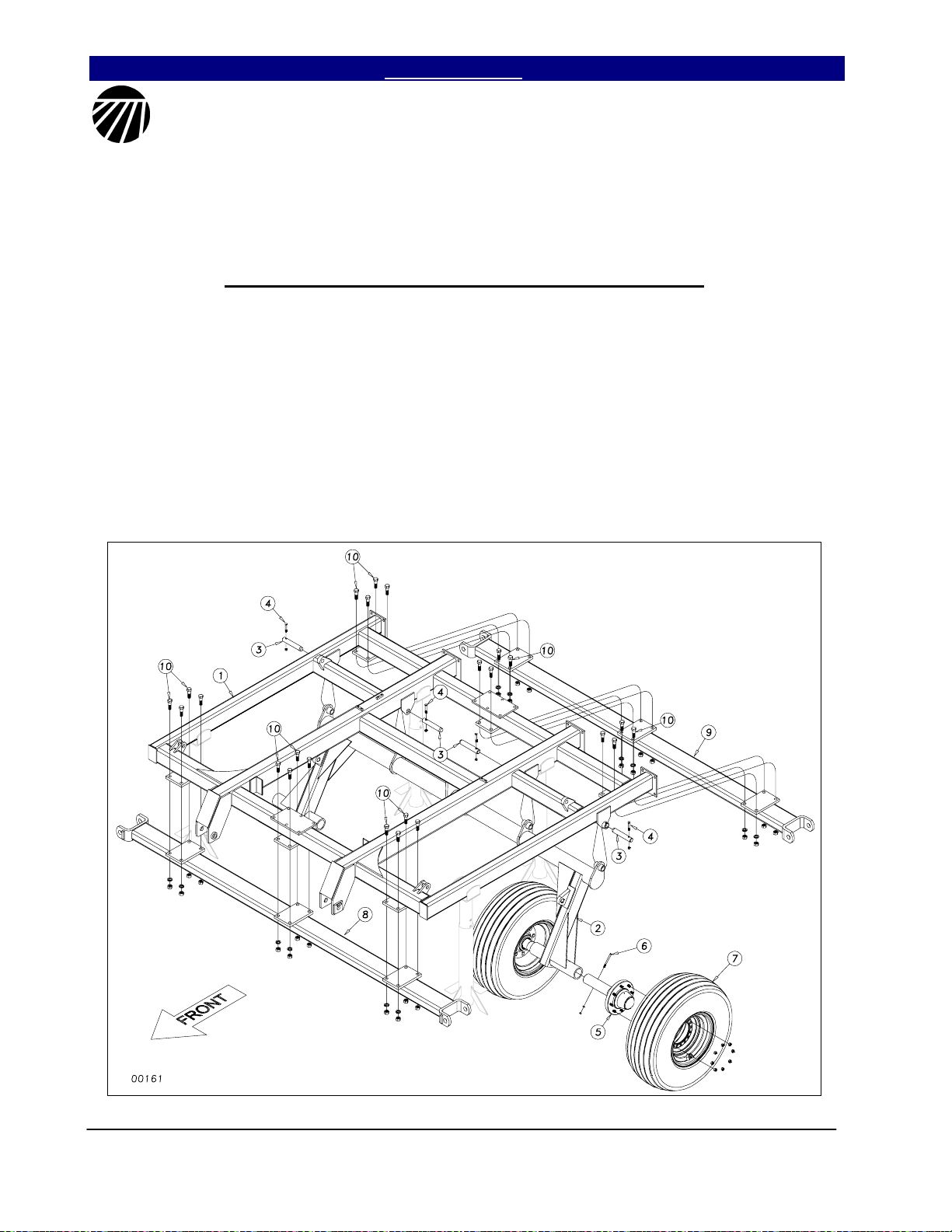
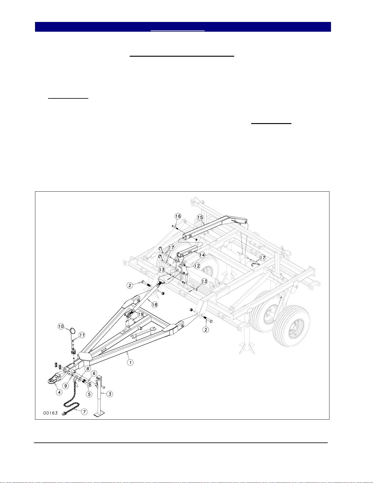
Center Frame, Torque Tube & Gang Bar Assembly
After uncrating the machine, place the
center frame (1) Figure 1, in the center of your
work area on stands. Pin the torque tube (2) to
the center frame with the 1¼ x 7 pins (3) and
secure them with the 3/8 x 2½ hex bolts (4) and
lock nuts.
Slide the hub & spindle assemblies (5)
into the sleeves at the end of the torque tube
wheel arms (refer to Section 3 for proper size
for your model). Use some form of anti-seize
on the spindle before you insert it. Line up the
hole in the spindle with the hole in the sleeve
and secure with 5/16 or ¾ hex bolt (6) with
lock washer and hex nut. Attach the proper tire
and wheel assembly (7) for your model as per
Section 3.
Bolt the front and rear gang bars (8) &
(9) to the center frame using ¾ x 2½ hex bolts
(10), hex nuts and lock washers. Note: the
heavier, weighted gang bar goes on the front.
Figure 1
Series I 1000TT- 4000TT Turbo-Till 586-043M 12/15/2004
3/21/2005
14
Page 17
Great Plains Mfg., Inc. Table of Contents ► Section 1: Assembly
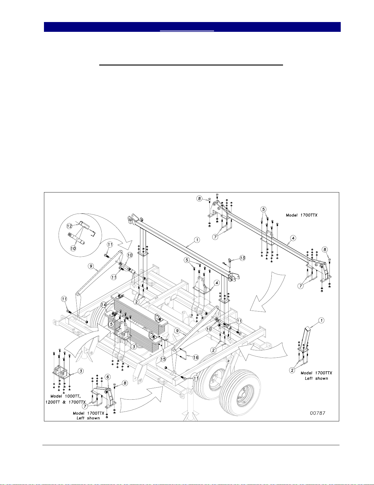
Center Wing Stop, Fold Brackets & Lift Assembly
On folding models, attach the center
wing stop (1) Figure 2, to the center frame
with 5/8 x 3 x 6½ u-bolts (2), using hex nuts
and lock washers (See Machine Layout for
proper placement). Bolt the front wing fold
bracket (3), and rear fold bracket (4), if
applicable, to the center frame using 5/8 x 2
GR 8 hex bolts (5), hex nuts and lock
washers. On 1700TTX* also assemble Inside
Hinges (6) to front bar using 5/8 x 4 x 6½ ubolts (7) and ¾ x 3½ hex bolts (8) with lock
washers and hex nuts.
lift mechanism link (10) to the center frame
using 1 x 3 hex bolts (11) and secure with 1”
lock nuts. Install transport locks (12) to the
lift mechanism links (10) with a 5/16 x 3
quick pin. Install the ¾ x 5¼ usable pin &
retainer (13) in the holders for the wing fold
locks.
package, insert the weight pairs (14) onto the
center frame. Secure them with weight box
stops (15) and ½ x 6 x 5¼ u-bolts (16), hex
nuts and lock washers.
Bolt the cylinder mount bars (9) and
If you have the optional center weight
Figure 2
12/15/2004 Series I 1000TT- 4000TT Turbo-Till 586-043M
1/25/2008
* Model 1700TTX is 5 meter foreign export model, not sold in USA.
15
Page 18
Section 1: Assembly Table of Contents ► Great Plains Mfg., Inc.
Hitch & Self Level Assembly
Bolt the hitch frame (1), Figure 3, to
the center frame with two 1¼ x 8 Gr. 8 hex
bolts (2). Draw up snug with a 1¼ top lock
nut, do not torque, as this part must pivot in
operation. Install the side wind jack (3) to
support the front of the hitch frame. Bolt the
cat III or IV hitch (4) to the hitch frame with a
1 x 8 Gr. 8 hex bolt (5) and a 1 x 6½ Gr. 8
hex bolt (6) as shown. Install the safety chain
(7) on the long bolt as shown with one 3”
washer (8) and one 1¾” spacer (9). Secure
these bolts with 1” hex nuts and lock washers.
Bolt the spring hose loop (10) onto the
hitch frame with a ½ x 1 hex bolt (11), two
flat washers and one lock washer. Pin the
level bar rocker (12) to the fold bracket with
two 1 x 3 clevis pins (13), use a machine
washer and 3/16 x 2 cotter. Insert the level
bar slide tube (14) into the level bar weldment
(15) and secure with a ¾ x 5½ hex bolt (16)
and nylon lock nut, do not torque nut. Install
the assembly to the torque tube and level bar
rocker (12) with 1 x 9½ pins (17) and 3/8 x 1
¾ quick pins. Install the turnbuckle (18)
between the level bar rocker (12) and hitch
frame (1) with a 1 x 9½ pin (17), 3/8 x 1¾
quick pin and a 1 x 4 clevis pin (19), using a
machine washer and 3/16 x 2 cotter.
Figure 3
Series I 1000TT- 4000TT Turbo-Till 586-043M 12/15/2004
3/21/2005
16
Page 19
Great Plains Mfg., Inc. Table of Contents ► Section 1: Assembly
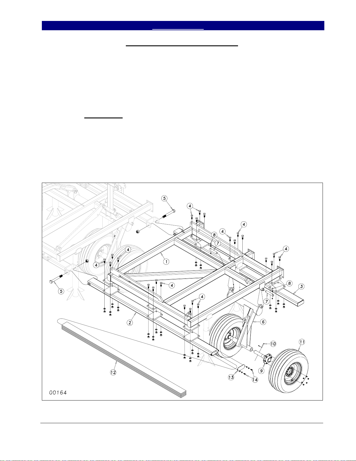
Wing and Wheel Arm Assembly
Place the wing frames (1) Figure 4, on
stands next to the center frame. Bolt the front
and rear gang bars (2) & (3) to the wing frame
using ¾ x 2½ hex bolts (4), nuts and lock
washers. Bolt the wing and gang bar assembly
to the center frame with two 1¼ x 10 Gr. 5 hex
bolts (5) with top lock nuts. Draw the nuts
down tight but do not torque.
Once the wings are attached, insert the
wheel arm bracket (6) into the wing frame
hangers and secure it with 1¼ x 7 pins (7).
Secure the 1¼ x 7 pins with 3/8 x 2½ hex bolts
(8), hex nuts and lock washers.
Slide the wing hub & spindle
assemblies (9) into the sleeves at the end of the
wheel arms (refer to Section 3 for proper size
for your model). Use some form of anti-seize
on the spindle before you insert it. Line up the
hole in the spindle with the hole in the sleeve
and secure with pin or bolt (10) as shown in
Section 3. Attach the wing tire and wheel
assembly (11) to the hubs using bolts or lug
nuts, (see Section 3).
With some heavy attachments, insert
the wing weight ballast flats (12) into the front
wing gang bar (2). Bolt the end caps (13) to the
front gang bar (2) with two ½ x 1 hex bolts (14)
using flat washers and lock washers.
Figure 4
12/15/2004 Series I 1000TT- 4000TT Turbo-Till 586-043M
3/21/2005
17
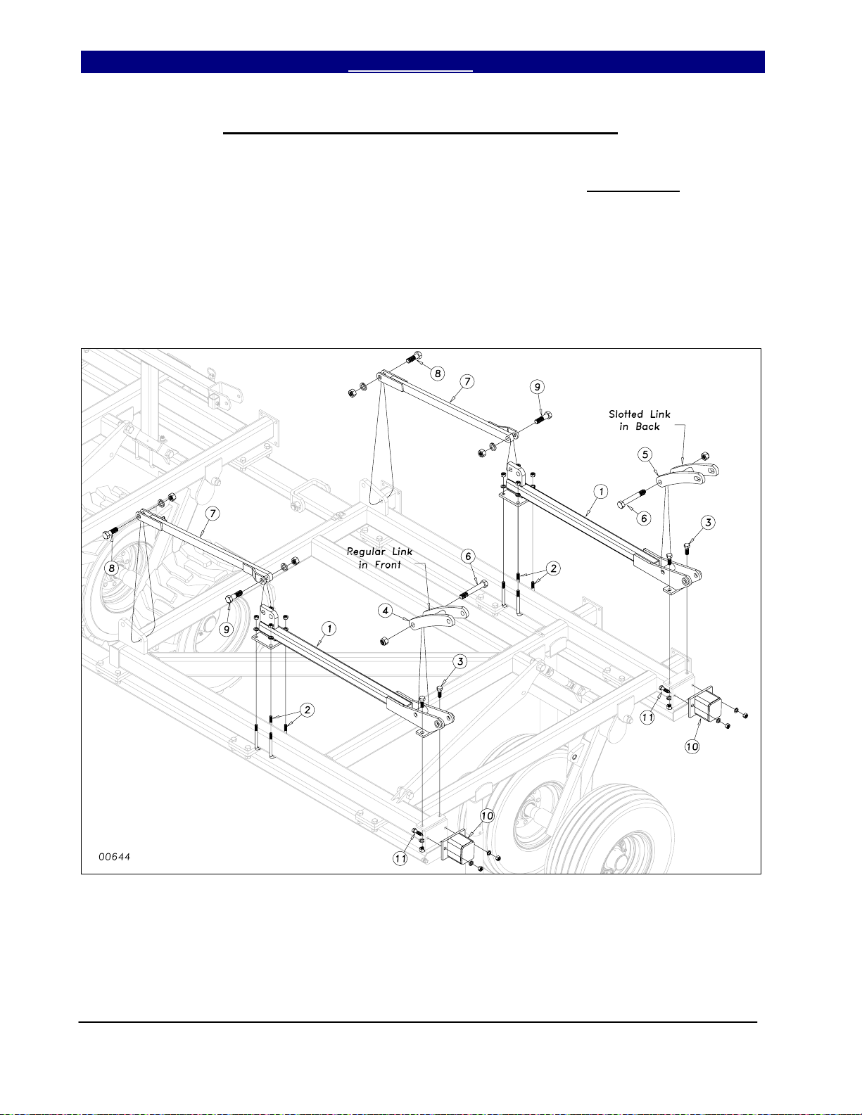
Page 20
Section 1: Assembly Table of Contents ► Great Plains Mfg., Inc.
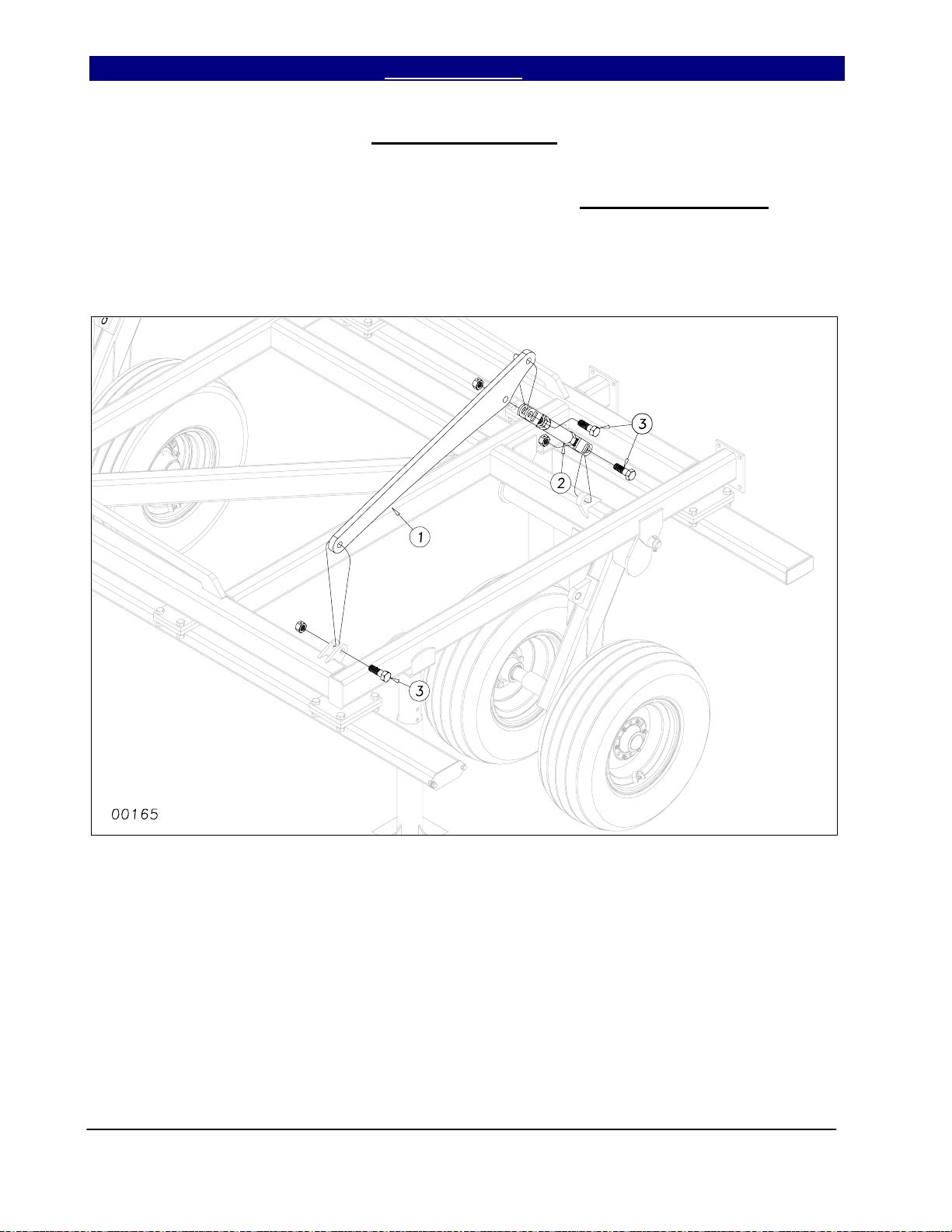
Wing Lift Assembly
Bolt the cylinder mount bar (1), Figure
5, and wheel arm turnbuckle (2) to the wing
frame using 1 x 3 hex bolts (3) and secure with
1” lock nuts. Do not torque these nuts,
turnbuckle must extend and retract freely.
Figure 5
Series I 1000TT- 4000TT Turbo-Till 586-043M 12/15/2004
18
Page 21
Great Plains Mfg., Inc. Table of Contents ► Section 1: Assembly
1700TTX* Wing Assembly
Place the 1700TTX* wing frames (1)
Figure 6, on stands next to the center frame.
Bolt the front and rear gang bars (2) to the wing
frame using ¾ x 2½ hex bolts (3), nuts and lock
washers. Bolt the Outside hinges, front and
rear, (4) & (5), to the wing frame with ¾ x 2
hex bolts (6) using lock washers and hex nuts.
Attach the wing assembly to the center
frame with two 1¼ x 4½ hardened pins (7),
secure with 3/8 x 2¼ Gr. 8 hex bolts (8) and 3/8
lock nuts. Bolt the two 9” fold links (9) to the
rear outside hinge (5), with 1 x 6 Gr. 8 1¾
thread hex bolts (10), secure with 1” nylon lock
nut but do not torque. Bolt the fold H-Bracket
(11) to the center fold bracket with 1 x 7¾ Gr.
8 special thread bolts (12), insert two flat
washers (13) and secure with 1” nylon lock nut
but do not torque links must rotate freely.
Figure 6
* Model 1700TTX is 5 meter foreign export model, not sold in USA.
12/15/2004 Series I 1000TT- 4000TT Turbo-Till 586-043M
10/06/2005
19
Page 22
Section 1: Assembly Table of Contents ► Great Plains Mfg., Inc.
40’ Wing Fold Strap & Fold Bracket Assembly
Bolt the Cylinder Mount/Hinges (1) to
the inside wing frame, Figure 7, with 5/8 x 4
x 6½ u-bolts (2) and 3/4 x 2 hex bolts (3),
using lock washers and hex nuts. Insert the
front and back curved fold links (4) and (5)
into the fold brackets (1) as shown and secure
with 1 x 7 Gr. 8 special thread hex bolts (6)
and nylon lock nuts, do not torque. Bolt the
fold straps (7) to the wing frame assembly
with 1 x 3 hex bolts (8) and 1 x 3½ hex bolts
(9) using hex nuts and lock washers. Attach
the two Wing Flex Limiters (10) to the inside
wing frame with 5/8 x 2 Gr. 8 hex bolts (11)
securing with lock washers and hex nuts.
Figure 7
Series I 1000TT- 4000TT Turbo-Till 586-043M 12/15/2004
3/21/2005
20
Page 23

Great Plains Mfg., Inc. Table of Contents ► Section 1: Assembly
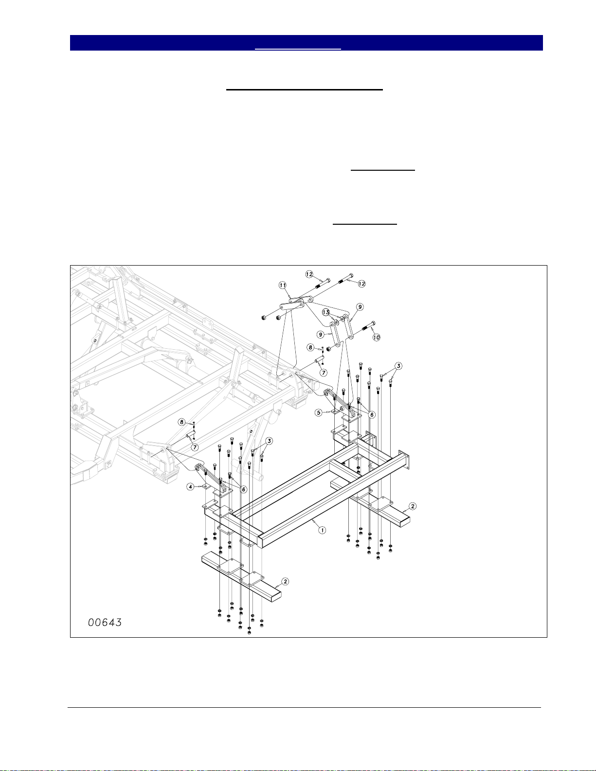
40’ Outside Wing Assembly
Bolt the outside wing fold bracket (1),
Figure 8, to the outside wing (2) using 3/4 x 2
hex bolts (3) using hex nuts and lock washers.
Attach the outside wing assembly to the
inside wing using two 1 x 6 special hex bolts
(4) using nylon lock nuts. Draw the nuts
down tight but do not torque. Bolt the front
and rear gang hanger bars (5) to the outside
wing with ¾ x 2½ hex bolts (6) using hex
nuts and lock washers. Pin the rocker links (7)
to the outside wing fold brackets (1) using 1 x
3 3/8 usable clevis pins (8), machine washers
& 3/16 x 2 cotter. Finally, bolt the rocker link
(7) to the inside wing assembly with a 1 x 7
Gr. 8 hex bolt (9), use four flat washers as
shown and secure with a 1” nylon lock nut, do
not torque.
Figure 8
12/15/2004 Series I 1000TT- 4000TT Turbo-Till 586-043M
3/21/2005
21
Page 24

Section 1: Assembly Table of Contents ► Great Plains Mfg., Inc.
Hydraulic Valve Mounting Assembly
Install the depth stop mounting bracket
(1), Figure 9, to the center frame using one 5/8
x 4 x 6½ u-bolt (2), lock washers and hex nuts.
Bolt the depth stop valve (3) on top of the
bracket using the 5/16 x 2” hex bolts (4) along
with lock washers. Insert the depth stop tube
(5) into the mounting bracket (1) and attach to
the level bar with ½ flat washer and 5/32 x 1½
cotter pin (6). Bolt the depth stop assembly (7)
onto the depth stop tube (1) with two ½ x 2½
hex bolts (8) securing with lock washers and
hex nuts.
Figure 9
For 17’, 22’ and 30’ machines, attach
the valve mounting bracket (1) and backing
plate (2) to the hitch frame as shown in Figure
10. Use four ½ x 4½ hex bolts (3) with hex
nuts and lock washers. Attach the bypass/
pressure reducing valve (4) with 5/16 x 3 hex
bolts (5), hex nuts and lock washers.
For 40’ machine, add second and third
bracket as shown in Figure 11. Use four ½ x 5
½ hex bolts (6) with hex nuts and lock washers.
Figure 10
Bolt the pressure reducing valves (4) to
the brackets with ¼ x 2½ hex bolts (5) Attach
the bypass valve (7) with 5/16 x 3 hex bolts (8),
hex nuts and lock washers.
Figure 11
Series I 1000TT- 4000TT Turbo-Till 586-043M 12/15/2004
3/21/2005
22
Page 25

Great Plains Mfg., Inc. Table of Contents ► Section 1: Assembly
Hydraulic Cylinder Purging Procedure
Pin the base end of the hydraulic fold
cylinders (1) to the fold bracket as in Figure 12.
Use 1” Clevis pins (3), machine washers and
3/16 x 2 cotter pins. Do Not connect the rod
end of the fold cylinders until they are charged
with oil. Follow the plumbing diagrams for the
lift and fold hydraulic systems, Section 2,
starting on page 28. Pay close attention to the
model and hydraulic options associated with
you machine. After the two systems are fully
plumbed, they need to be fully purged of air
before pinning cylinders to machine. To fully
purge a rephasing system, the rephasing port
(round knob on cylinder barrel) needs to be the
highest point of oil during purging (air bubbles
rise upward). With the lift and fold cylinders
unpinned and blocked up safely with rephrasing
port at top, cycle the cylinders for both systems
4 to 5 times from fully retracted to fully
extended while checking for leaks, lift cylinders
(2) will need to be set up on frame while
purging. You may then attach the cylinders in
their final locations.
Figure 12
12/15/2004 Series I 1000TT- 4000TT Turbo-Till 586-043M
23
Page 26

Section 1: Assembly Table of Contents ► Great Plains Mfg., Inc.
Turbo Gang Placement
All turbo gangs are pre-assembled at the
factory. For assembly and diss-assembly of the
turbo gangs and scrapers, refer to the diagram
in section 3 Replacements Parts, Gang
Assembly, page 52.
Arrange the turbo gangs under the
machine as illustrated in Figures 13 thru 18 for
your model machine. Using ¾ x 6 hex bolts
and 5/8 x 6½ hex bolts, hex nuts and lock
washers, bolt the gangs to the gang bars. Refer
to the machine layout diagrams in Section 4,
page 54 for the placement dimensions for
attaching the gangs to the gang bars. Make
sure that the C-shank bearing hangers are
vertical and perpendicular to the gang bar. Also
note the different orientation of the bearing
hanger bracket between right side and left side
(see bottom of Figures 13 thru 18).
Figure 13
Series I 1000TT- 4000TT Turbo-Till 586-043M 12/15/2004
3/21/2005
24
Page 27

Great Plains Mfg., Inc. Table of Contents ► Section 1: Assembly
Figure 14
Figure 15
12/15/2004 Series I 1000TT- 4000TT Turbo-Till 586-043M
10/06/2005
25
Page 28

Section 1: Assembly Table of Contents ► Great Plains Mfg., Inc.
Figure 16
Series I 1000TT- 4000TT Turbo-Till 586-043M 12/15/2004
26
Page 29

Great Plains Mfg., Inc. Table of Contents ► Section 1: Assembly
Figure 17
12/15/2004 Series I 1000TT- 4000TT Turbo-Till 586-043M
27
Page 30

Section 1: Assembly Table of Contents ► Great Plains Mfg., Inc.
Figure 18
Series I 1000TT- 4000TT Turbo-Till 586-043M 12/15/2004
28
Page 31

Great Plains Mfg., Inc. Table of Contents ► Section 1: Assembly
Completing Setup
If the machine has a finishing
attachment, install it according the instructions
shipped with the attachment.
Once the finishing attachment is
installed and all of the hydraulic procedures
have been completed, you may fold the
machine to check for clearance and
interferences. Slowly fold the machine while
watching that hoses do not become pinched or
kinked while watching for interferences.
Once the machine is folded completely,
begin to unfold slowly. Be Sure No One Is
Under The Wings When You Unfold The
Machine. Once the machine is unfolded, add
the safety decals and the product decals. Refer
to Important Safety Information section (page
7) for the proper placement of safety decals.
safety lights in accordance with local and state
laws. See parts manual (Section 6: Safety) for
assembly drawings and parts list.
instructions, Section 5, page 68, for the first
time field adjustments before going to the field
for the first time.
Install the safety chain, SMV sign &
Be sure to consult the operating
12/15/2004 Series I 1000TT- 4000TT Turbo-Till 586-043M
3/21/2005
29
Page 32

Section 2: Hydraulics Table of Contents ► Great Plains Mfg., Inc.
Hydraulic Lift System 1000TT, 1200TT & 1700TT
00470
Series I 1000TT - 4000TT Turbo-Till 586-043M 12/15/2004
30
Page 33

Great Plains Mfg., Inc. Table of Contents ► Section 2: Hydraulics
Hydraulic Lift System 1000TT, 1200TT & 1700TT
Ref Kent No. GP Part No. Part Description Comments
1. 810-502C CYL REP 3.75 x 10 x 1.38 Rod (Tie) GP Seal Kit# 810-373C
2. FC0218 810-511C Depth Control Valve Cartridge #3C7272
3. 810-116C Counterbalance Valve MAN. T.T.
4. 811-088C Adaptor, AD 3/4 MORB 3/4 MJIC
5. 811-063C Elbow, EL 3/4MJIC 3/4MORB
6. 811-078C Tee, TE 3/4MJIC
7. HF0034 811-203C Plug, PL 3/4MORB HOLLOW HEX
8. 841-019C HH1/2R1 144 3/4FJIC 3/4MORB
9. 841-020C HH1/2R1 042 3/4FJIC
10. 811-830C HH1/2R1 084 3/4FJIC
11. 841-021C HH1/2R1 090 3/4FJIC
12. 811-831C HH1/2R1 034 3/4FJIC
13. 811-832C HH1/2R1 068 3/4FJIC
14. 811-826C Hydra Grip Handle, Black Extend
15. 811-913C Hydra Grip Handle, Black Retract
16. 811-919C Adaptor, AD 3/4 MORB 3/4 FORB (HG)
17. 548-001S HG Pair Black MORB-FORB Includes items 14 thru 16
18. 811-394C Coupler, CP 3/4 FORB MALE QD Poppet Type
19. 575-268D Hose Wrap, Large Size, Short 8”
550-123D Hose Wrap, Small Size, Short 8”
12/15/2004 Series I 1000TT - 4000TT Turbo-Till 586-043M
31
Page 34

Section 2: Hydraulics Table of Contents ► Great Plains Mfg., Inc.
Hydraulic Lift System 2200TT, 3000TT & 4000TT
00471
Series I 1000TT - 4000TT Turbo-Till 586-043M 12/15/2004
32
Page 35

Great Plains Mfg., Inc. Table of Contents ► Section 2: Hydraulics
Hydraulic Lift System 2200TT, 3000TT & 4000TT
Ref Kent No. GP Part No. Part Description Comments
1. 810-501C 4x10x1 3/8 rod Reph Cylinder, Kit# 810-151C Model 2200TT & 3000TT
810-517C 4.25x10x1.50 rod Reph Cylinder, Kit# 810-144C Model 4000TT
2. 810-502C 3 3/4x10x1 3/8 rod Reph Cylinder, Kit# 810-373C Model 2200TT & 3000TT
810-501C 4x10x1 3/8 rod Reph Cylinder, Kit# 810-151C Model 4000TT
3. FC0218 810-511C Depth Control Valve Cartridge #3C7272
4. 810-116C Counterbalance Valve MAN. T.T.
5. 811-088C Adaptor, AD 3/4 MORB 3/4 MJIC
6. 811-063C Elbow, EL 3/4MJIC 3/4MORB
7. 811-078C Tee, TE 3/4MJIC
8. 811-203C Plug 3/4MORB HOLLOW HEX
9. 841-019C HH1/2R1 144 3/4FJIC 3/4MORB
10. 841-020C HH1/2R1 042 3/4FJIC
11. 811-830C HH1/2R1 084 3/4FJIC
12. 841-021C HH1/2R1 090 3/4FJIC
13. 811-831C HH1/2R1 034 3/4FJIC
14. 811-832C HH1/2R1 068 3/4FJIC
15. 811-833C HH1/2R1 094 3/4FJIC Model 2200TT
811-842C HH1/2R1 150 3/4FJIC Model 3000TT
811-846C HH1/2R1 174 3/4FJIC Model 4000TT
16. 811-834C HH1/2R1 122 3/4FJIC Model 2200TT
811-843C HH1/2R1 166 3/4FJIC Model 3000TT
841-114C HH1/2R1 192 3/4FJIC Model 4000TT
17. 811-835C HH1/2R1 158 3/4FJIC Model 2200TT
811-844C HH1/2R1 202 3/4FJIC Model 3000TT
811-850C HH1/2R1 226 3/4FJIC Model 4000TT
18. 811-826C Hydra Grip Handle, Black Extend
19. 811-913C Hydra Grip Handle, Black Retract
20. 811-919C Adaptor, AD 3/4 MORB 3/4 FORB (HG)
21. 548-001S HG Pair Black MORB-FORB Includes items 18 thru 20
22. 811-394C Coupler, CP 3/4 FORB MALE QD Poppet Type
23. 575-268D Hose Wrap, Large Size, Short 8”
550-123D Hose Wrap, Small Size, Short 8”
12/15/2004 Series I 1000TT - 4000TT Turbo-Till 586-043M
3/29/2007
33
Page 36

Section 2: Hydraulics Table of Contents ► Great Plains Mfg., Inc.
Hydraulic Fold System 1700TT, 2200TT & 3000TT
00472
Series I 1000TT - 4000TT Turbo-Till 586-043M 12/15/2004
10/06/2005
34
Page 37

Great Plains Mfg., Inc. Table of Contents ► Section 2: Hydraulics
Hydraulic Fold System 1700TT, 2200TT & 3000TT
Ref Kent No. GP Part No. Part Description Comments
1. 810-490C CYL 4x24x2 Rod (Tie) 34.63 C.L. 1700TT. GP Seal Kit# 810-014C
810-495C CYL 4x36x2 Rod (Tie) 46.25 C.L. 2200TT & 3000T T. Kit# 810-014C
2. 810-512C Valve, Bypass/Pressure Reducing with Check GP Seal Kit # 810-515C
3. HF0190 810-300C 3000 PSI Oil Filled Pressure Gauge
4. 810-532C Filter, Inline 3/4 MORB 3/4 MJIC (S/N 1367NN+)
5. 811-088C Adaptor, AD 3/4MORB 3/4MJIC
6. 811-063C Elbow, EL 3/4MJIC 3/4MORB
7.
n 811-845C Replaced by 196-430D
8. 811-677C Adaptor, AD 9/16MORB 1/4FNPT
9. 811-078C Tee, TE 3/4MJIC See note below
10. 811-147C Cross, CR 3/4MJIC See note below
11. 811-882C HH3/8R2 152 3/4FJIC 3/4MORB
12. 811-978C HH3/8R2 093 3/4FJIC Model 1700TTX*, 1700TT(S/N 2026NN-)
811-837C HH3/8R2 048 3/4FJIC Model 1700TT(S/N 2027NN+),
2200TT & 3000TT
13. 811-838C HH3/8R2 042 3/4FJIC
14. 811-839C HH3/8R2 074 3/4FJIC
15. 811-841C HH3/8R2 024 3/4FJIC
16. 811-839C HH3/8R2 074 3/4FJIC Model 3000TT
17. 811-915C Hydra Grip Handle - Green Extend
18. 811-916C Hydra Grip Handle - Green Retract
19. 811-919C Adaptor, AD 3/4 MORB 3/4 FORB (HG)
20. 548-003S HG Pair Green MORB-FORB Includes items 17 thru 19
21. 811-394C Coupler, CP 3/4FORB Male QD Poppet Type
o 196-430D Orifice Restrictor, ORPL 1/16 3/4MORB
Notes: Models 1700TT & 2200TT use only two fold cylinders on machine. Model 3000 TT uses four cylinders.
* Model 1700TTX is 5 meter foreign export model, not sold in USA
Legend: n = 1st revision; o = 2nd revision, p = 3rd revision; z use up existing stock; ⊗ not interchangeable; ⊗coRevision 2 is not interchangeable with 1
12/15/2004 Series I 1000TT - 4000TT Turbo-Till 586-043M
10/06/2005
35
Page 38

Section 2: Hydraulics Table of Contents ► Great Plains Mfg., Inc.
Hydraulic Fold System 4000TT (S/N 1990NN+)
00713
Series I 1000TT - 4000TT Turbo-Till 586-043M 12/15/2004
8/30/2005
36
Page 39

Great Plains Mfg., Inc. Table of Contents ► Section 2: Hydraulics
Hydraulic Fold System 4000TT (S/N 1990NN+)
Ref Kent No. GP Part No. Part Description Comments
1. 810-495C 4 x 36 x 2” Rod Cylinder (46.25 C.L.) GP Seal Kit# 810-014C
2. 810-487C 4 x 24 x 1.50 Rod Cylinder (34.63 C.L.) GP Seal Kit# 810-060C
3. 810-432C Hydraulic Bypass Valve
4. 810-301C Valve, Pressure Reducing w/Check
5. 810-532C Filter, Inline 3/4 MORB 3/4 MJIC
6. 811-088C Adaptor, AD 3/4 MORB 3/4 MJIC
7. 811-063C Elbow, EL 3/4 MJIC 3/4 MORB
8. 196-430D Orifice Restrictor, ORPL 1/16 3/4MORB
9. 811-584C Adaptor, AD 9/16MORB 3/4MJIC
10. 811-216C Elbow, EL 3/4 MJIC 9/16 MORB
11. HF0195 811-281C Elbow, EL 3/8 FNPT 9/16 MORB
12. 811-078C Tee, TE 3/4 MJIC
13. 811-077C Tee, TE 3/4 MORB 3/4 MJIC 3/4 MJIC
14. 152-498D Orifice Restrictor, ORPL 1/8 8 MORB
15. 811-147C Cross, CR 3/4 MJIC
16. HF0189 811-255C Adaptor, AD 3/8 MNPT 1/4 FNPT
17. 811-073C Tee, TE 3/4 MJIC 3/4 MJIC 3/4 FJIC
18. HF0190 810-300C 3000 PSI Oil Filled Pressure Gauge
19. 811-882C HH3/8R2 152 3/4FJIC 3/4MORB
20. 811-639C HH3/8R2 013 3/4FJIC
21. 811-847C HH3/8R2 009 3/4FJIC
22. 811-837C HH3/8R2 048 3/4FJIC
23. 811-839C HH3/8R2 074 3/4FJIC
24. 811-838C HH3/8R2 042 3/4FJIC
25. 811-848C HH3/8R2 054 3/4FJIC
26. 811-849C HH3/8R2 090 3/4FJIC
27. 811-897C HH3/8R2 123 3/4FJIC
28. 811-671C HH3/8R2 099 3/4FJIC
29. 841-011C HH3/8R2 131 3/4FJIC
30. 811-237C HH3/8R2 174 3/4FJIC
31. 811-909C HH3/8R2 163 3/4FJIC
32. 811-126C HH3/8R2 140 3/4FJIC
33. 811-978C HH3/8R2 093 3/4FJIC
34. 811-915C Hydra Grip Handle - Green Extend
35. 811-916C Hydra Grip Handle - Green Retract
36. 811-919C Adaptor, AD 3/4 MORB 3/4 FORB (HG)
37. 548-003S HG Pair Green MORB-FORB Includes items 34 thru 36
38. 811-394C Coupler, CP 3/4FORB Male QD Poppet Type
12/15/2004 Series I 1000TT - 4000TT Turbo-Till 586-043M
8/30/2005
37
Page 40

Section 2: Hydraulics Table of Contents ► Great Plains Mfg., Inc.
Hydraulic Hose Layouts
00232
Series I 1000TT - 4000TT Turbo-Till 586-043M 12/15/2004
38
Page 41

Great Plains Mfg., Inc. Table of Contents ► Section 2: Hydraulics
00788
00789
12/15/2004 Series I 1000TT - 4000TT Turbo-Till 586-043M
10/06/2005
39
Page 42

Section 2: Hydraulics Table of Contents ► Great Plains Mfg., Inc.
00174
00175
Series I 1000TT - 4000TT Turbo-Till 586-043M 12/15/2004
40
Page 43

Great Plains Mfg., Inc. Table of Contents ► Section 2: Hydraulics
00176
00177
12/15/2004 Series I 1000TT - 4000TT Turbo-Till 586-043M
41
Page 44

Section 2: Hydraulics Table of Contents ► Great Plains Mfg., Inc.
00224
Series I 1000TT - 4000TT Turbo-Till 586-043M 12/15/2004
8/30/2005
42
Page 45

Great Plains Mfg., Inc. Table of Contents ► Section 2: Hydraulics
00225
12/15/2004 Series I 1000TT - 4000TT Turbo-Till 586-043M
8/30/2005
43
Page 46

Section 2: Hydraulics Table of Contents ► Great Plains Mfg., Inc.
17’, 22’ & 30’ Hydraulic Down Pressure Preparation and Setup
Note: This setup procedure is for tractors with closed-center or pressure compensated flow
hydraulic systems. Open center hydraulics not supported.
1. Adjust the bypass/pressure reducing
valve by turning knob (1), Figure 1,
clockwise all the way in and then backing
out 1 full turn.
2. On tractor, adjust flow-control valve to low
side of flow rate. NOTE
flow of oil through the system the greater
potential for oil heating, premature wear
or tractor damage.
3. Lock the fold hydraulic lever for
continuous downward oil flow.
4. Adjust bypass/pressure reducing valve
knob (2) on implement so the pressure
gauge reads 1200 psi. Never exceed
1400 psi.
5. While watching pressure gauge, slowly open
valve knob (1) until gauge reads 1100 psi.
Pressure might rise and then fall off as knob
is opened. If pressure exceeds 1400 psi
: The faster the
during this step, the tractor flow is too high,
reduce tractor flow. Lock valve knob (1) at
1100 psi.
6. Finally adjust valve (2) to the desired wing
down pressure setting of 300 to 400 psi.
Never exceed 700 psi.
7. In field operation, Lock the fold
hydraulic lever for continuous
downward oil flow. If wings are
running too high, increase pressure
setting, knob (2), to level machine. If
center is too high, decrease pressure
setting with knob (2) on valve.
8. Caution: Never leave tractor valve
centered when unfolded with machine
in motion. Machine damage may occur
!
when wings flex up or down (see page
69).
Figure 1
Series I 1000TT - 4000TT Turbo-Till 586-043M 1/25/2008
44
Page 47

Great Plains Mfg., Inc. Table of Contents ► Section 2: Hydraulics
40’ Hydraulic Down Pressure Preparation and Setup
Note: This setup procedure is for tractors with closed-center or pressure compensated flow
hydraulic systems. Open center hydraulics not supported.
1. Adjust the bypass valve by turning knob
(1), Figure 2, clockwise all the way in and
then backing out 1 full turn.
2. On tractor, adjust flow-control valve to low
side of flow rate. NOTE
flow of oil through the system the greater
potential for oil heating, premature wear
or tractor damage.
3. Lock the fold hydraulic lever for
continuous downward oil flow.
4. Adjust pressure reducing valves knob (2
& 3) on implement so the pressure
gauges reads 1200 psi each. Never
exceed 1400 psi.
5. While watching pressure gauges, slowly
open bypass valve, knob (1) until gauges
reads around 1100 psi. Pressure might rise
and then fall off as knob is opened. If
pressure exceeds 1400 psi during this step,
: The faster the
!
the tractor flow is too high, reduce tractor
flow. Lock bypass valve knob (1) at 1100 psi.
6. Finally adjust valve knob (2) to 650-900 psi
pressure setting, never exceeding 1100 psi.
Adjust valve knob (3) to 650-750 psi.
pressure setting, never exceeding 1000 psi.
7. In field operation, Lock the fold
hydraulic lever for continuous
downward oil flow. If wings are
running too high, increase pressure
setting to the appropriate valve, knob
(2 or 3), to level machine. If center is
too high, decrease pressure setting
with knob (2) on Inside wing valve.
8. Caution: Never leave tractor valve
centered when unfolded with machine
in motion. Machine damage may occur
when wings flex up or down (see page
69).
Figure 2
1/25/2008 Series I 1000TT - 4000TT Turbo-Till 586-043M
45
Page 48

Section 3: Replacement Parts Table of Contents ► Great Plains Mfg., Inc.
1000TT Center Transport Assembly
00641
Series I 1000TT - 4000TT Turbo-Till 586-043M 12/15/2004
3/21/2005
46
Page 49

Great Plains Mfg., Inc. Table of Contents ► Section 3: Replacement Parts
1000TT Center Transport Assembly
Ref. Kent No. GP Part No. Part Description Comments
1. 815-136C 3000 KG Brake-Hub Assembly
2. 111272 802-192C Hex Bolt, 3/4 x 4 1/2, Gr.5
3. 4112 804-023C Lock Washer, 3/4
4. 3012 803-027C Hex Nut, 3/4
5. 111232 802-064C Hex Bolt, 3/4 x 2
6. 814-200C NTA2000 Exp. Tire/Wheel Assembly
12/15/2004 Series I 1000TT - 4000TT Turbo-Till 586-043M
47
Page 50

Section 3: Replacement Parts Table of Contents ► Great Plains Mfg., Inc.
1200TT, 1700TT & 2200TT Center Transport Assembly
00140
Series I 1000TT - 4000TT Turbo-Till 586-043M 12/15/2004
1/25/2008
48
Page 51

Great Plains Mfg., Inc. Table of Contents ► Section 3: Replacement Parts
1200TT, 1700TT & 2200TT Center Transport Assembly
Ref. Kent No. GP Part No. Part Description Comments
1. FC1310 550-018D Spindle, 2 x 14 1/2 (Q783)
2. FC1311 816-426C Seal, HD Hub (W-783)
3. FC0299 822-048C Inner Cone, (LM501349)
4. FC0296 822-053C Inner Cup, (LM501310)
5. 800-130C Grease Zerk, 1/8-27 MPT
6. FC1312 815-193C 6-Bolt Heavy Hub w/cups (W-783)
7. FC0246 822-020C Outer Cup, (LM67010)
8. FC0248 822-021C Outer Cone, (LM67048)
9. 804-055C Washer, Spindle 7/8
10. FC0253 805-089C Cotter Pin, 5/32 x 1 1/2
11. FC0252 803-029C Slotted Hex Nut, 7/8-14
12. FC0254 890-781C Dust Cap
13.
14. 803-061C Nut Lug 9/16-18 x 90 PLT S/N 1924NN+
3408
120820
15.
FC1389
16. 210548 805-324C Clevis Pin, 5/16 x 3 w/cotter
17. 260216 805-363C Cotter Pin, 1/8 x 1
18. FC0419 814-221C Rim, 15 x 8, 6-Bolt, 1 1/8+ Offset
19. FC1767 814-226C Tire, 11L x 15, Load “F”
20. FC2288 814-237C 11L x 15 x 8 Load “F” Tire & Wheel Assy. Include items 18 & 19
802-799C Hub Stud 9/16-18 x 2 1/8 J1102 S/N 1942NN+
P151401 Stud Bolt 1/2-20 x 1 7/8” S/N 1941NN-
803-017C Lug Nut, 1/2-20 x 90 deg S/N 1941NN-
802-632C Lug Bolt, 1/2 x 1 1/4 Older version
815-195C Hub 6-Bolt Spindle 2.x14.5 890 Include items 1 thru 14
570-206S Replaced by 815-195C
Legend: = 1st revision; = 2nd revision, = 3rd revision; use up existing stock; ⊗ not interchangeable; ⊗Revision 2 is not interchangeable with 1
12/15/2004 Series I 1000TT - 4000TT Turbo-Till 586-043M
1/25/2008
49
Page 52

Section 3: Replacement Parts Table of Contents ► Great Plains Mfg., Inc.
3000TT Center Transport & 4000TT Wing Transport Assembly
00141
Series I 1000TT - 4000TT Turbo-Till 586-043M 12/15/2004
1/25/2008
50
Page 53

Great Plains Mfg., Inc. Table of Contents ► Section 3: Replacement Parts
3000TT Center Transport & 4000TT Wing Transport Assembly
Ref. Kent No. GP Part No. Part Description Comments
1. FC1812 570-056D Spindle, 2 3/4 x 17 (Q60-8B)
2. FC1827 816-220C Seal, (CR27362)
3. 822-110C Inner Cone, (JLM506849)
4. 822-109C Inner Cup, (JLM506810)
5. 800-130C Grease Zerk, 1/8-27 MPT
6. 815-176C Hub 8-Bolt(608) w/Brgs, Nuts, Cap
FC1813
7. 803-219C Lug Nut, 5/8-18 x 90
8. FC0426 822-053C Outer Cup, (LM501310)
9. FC0248 822-048C Outer Cone, (LM501349)
10. 913624
11. 805-017C Cotter Pin, 3/16 x 1 3/4
12. 803-095C Slotted Hex Nut, 1”-14
13. 890-277C Dust Cap
14.
FC1826
15.
110564
16. 3005 803-008C Hex Nut, 5/16
17. 4105 804-009C Lock Washer, 5/16
18. FC1836 814-223C Rim, 15 x 10, 8-Bolt, 3/8+ Offset
19. FC1769 814-227C Tire, 12.5L x 15, Load “F” 3000TT Center
814-247C Tire, 12.5L x 15, 12-ply 4000TT Wing
20. FC2282 814-256C 12.5L x 15 x 10 Load “F” Tire & Wheel Assy. Include items 18 & 19
814-248C 12.5L x 15 x 10 12-ply Tire & Wheel Ass y. Include items 18 & 19
815-164C 8-Bolt Hub Casting w/cups W60-8 Replaced by 815-176C
148-404D Washer, Spindle 1”
815-194C Hub 8-Bolt Spindle 2.75x17 608 Include items 1 thru 13
570-220S Replaced by 815-194C
802-802C Hex Bolt, 5/16-18 x 4 Gr.8
802-279C Hex Bolt, 5/16 x 4 Gr.5 Changed to 802-802C
Legend: = 1st revision; = 2nd revision, = 3rd revision; use up existing stock; ⊗ not interchangeable; ⊗Revision 2 is not interchangeable with 1
12/15/2004 Series I 1000TT - 4000TT Turbo-Till 586-043M
2/09/2006
51
Page 54

Section 3: Replacement Parts Table of Contents ► Great Plains Mfg., Inc.
4000TT Center Transport Assembly (S/N 2282NN+)
00875
Series I 1000TT - 4000TT Turbo-Till 586-043M 12/15/2004
1/25/2008
52
Page 55

Great Plains Mfg., Inc. Table of Contents ► Section 3: Replacement Parts
4000TT Center Transport Assembly (S/N 2282NN+)
Ref. Kent No. GP Part No. Part Description Comments
1. 576-114D Spindle, 2 3/4 x 17 (Q60-8)
2. FC1827 816-220C Seal, (CR27362)
3. 822-110C Inner Cone, (JLM506849)
4. 822-109C Inner Cup, (JLM506810)
5. 800-130C Grease Zerk, 1/8-27 MPT
6. 815-176C Hub 8-Bolt(608) w/Brgs, Nuts, Cap
7. 803-219C Lug Nut, 5/8-18 x 90
8. FC0426 822-053C Outer Cup, (LM501310)
9. FC0248 822-048C Outer Cone, (LM501349)
10. 913624
11. 805-017C Cotter Pin, 3/16 x 1 3/4
12. 803-095C Slotted Hex Nut, 1-14
13. 890-277C Dust Cap
14. 815-251C Hub 8-Bolt Spindl e 2.75x17 608 Include items 1 thru 13
15. 586-278D Pivot Spindle Turbotill
16. 586-279D Pivot Spindle Bushing
17. 816-551C Rubber 5.13OD x 3.06ID x 6.00
18.
19. 586-173H Walking Axle Bracket
20. 586-280D Pivot Spindle Washer
21. 148-404D Hardened Spindle Washer, 1”
22. 803-095C Slotted Hex Nut, 1-14
23. 805-017C Cotter Pin 3/16 x 1 3/4
24. 802-046C Hex Bolt, 1/2-13 x 5 1/2 Gr.5
25. 804-015C Lock Washer, 1/2
26. 803-020C Hex Nut, 1/2-13
27. 802-841C Hex Bolt, 3/4-10 x 2 1/2 Gr.8
28. 804-023C Lock Washer, 3/4
29. 803-027C Hex Nut, 3/4-10
30. 802-045C Hex Bolt, 1/2-13 x 5 Gr.5
31. 814-291C Rim, 16.5 x 12, 8-Bolt, 6Pilot Wht
32. 814-281C Tire Galaxy 32-15.5 x 16.5 Load G
33. 814-280C Tire/Wheel 32-15.5 x 16.5/G off white Items 31 & 32
34. 814-291C Rim, 16.5 x 12, 8-Bolt, 6Pilot White Optional Tire
35. 814-347C Tire Skid St 33x15.5x16.5 14 Ply Optional Tire
36. 814-348C RH TIRE/WHL 33x15.5x16.5 SKID8 Items 34 & 35
37. 814-349C LH TIRE/WHL 33x15.5x16.5 SKID8 Items 34 & 35
148-404D Washer, Spindle 1”
586-172H Walking Axle Receiver, RH
586-177H Walking Axle Receiver, LH
Legend: = 1st revision; = 2nd revision, = 3rd revision; use up existing stock; ⊗ not interchangeable; ⊗Revision 2 is not interchangeable with 1
12/15/2004 Series I 1000TT - 4000TT Turbo-Till 586-043M
1/25/2008
53
Page 56

Section 3: Replacement Parts Table of Contents ► Great Plains Mfg., Inc.
2200TT Wing Transport Assembly
00142
Series I 1000TT - 4000TT Turbo-Till 586-043M 12/15/2004
8/30/2005
54
Page 57

Great Plains Mfg., Inc. Table of Contents ► Section 3: Replacement Parts
2200TT Wing Transport Assembly
Ref. Kent No. GP Part No. Part Description Comments
1. FC1310 550-018D Spindle, 2 x 14 1/2 (Q783)
2. FC1311 816-426C Seal, HD Hub (W-783)
3. FC0299 822-048C Inner Cone, (LM501349)
4. FC0296 822-053C Inner Cup, (LM501310)
5. 800-130C Grease Zerk, 1/8-27 MPT
6. FC1312 815-193C 6-Bolt Heavy Hub w/cups (W-783)
7. FC0246 822-020C Outer Cup, (LM67010)
8. FC0248 822-021C Outer Cone, (LM67048)
9. 804-055C Washer, Spindle 7/8
10. FC0253 805-089C Cotter Pin, 5/32 x 1 1/2
11. FC0252 803-029C Slotted Hex Nut, 7/8-14
12. FC0254 890-781C Dust Cap
13.
14. 803-061C Nut Lug 9/16-18 x 90 PLT S/N 1924NN+
3408 803- 017C Lug Nut, 1/2-20 x 90 deg S/N 1941NN-
120820
15.
FC1389
16. 210548 805-324C Clevis Pin, 5/16 x 3 w/cotter
17. 260216 805-363C Cotter Pin, 1/8 x 1
18. FC0419 814-221C Rim, 15 x 8, 6-Bolt, 1 1/8+ Offset
19. FC1765 814-145C Tire, 11L x 15, 12-ply
20. FC2277 814-233C 11L x 15 x 8 12-ply Tire & Wheel Assy. Include items 18 & 19
802-799C Hub Stud 9/16-18 x 2 1/8 J1102 S/N 1942NN+
P151401 Stud Bolt 1/2-20 x 1 7/8” S/N 1941NN-
802-632C Lug Bolt, 1/2 x 1 1/4 Older version
815-195C Hub 6-Bolt Spindle 2.x14.5 890 Include items 1 thru 14
570-206S Replaced by 815-195C
Legend: = 1st revision; = 2nd revision, = 3rd revision; use up existing stock; ⊗ not interchangeable; ⊗Revision 2 is not interchangeable with 1
12/15/2004 Series I 1000TT - 4000TT Turbo-Till 586-043M
8/30/2005
55
Page 58

Section 3: Replacement Parts Table of Contents ► Great Plains Mfg., Inc.
3000TT Wing Transport Assembly
00143
Series I 1000TT - 4000TT Turbo-Till 586-043M 12/15/2004
8/30/2005
56
Page 59

Great Plains Mfg., Inc. Table of Contents ► Section 3: Replacement Parts
3000TT Wing Transport Assembly
Ref. Kent No. GP Part No. Part Description Comments
1. FC1310 550-018D Spindle, 2 x 14 1/2 (Q783)
2. FC1311 816-426C Seal, HD Hub (W-783)
3. FC0299 822-048C Inner Cone, (LM501349)
4. FC0296 822-053C Inner Cup, (LM501310)
5. 800-130C Grease Zerk, 1/8-27 MPT
6. FC1312 815-193C 6-Bolt Heavy Hub w/cups (W-783)
7. FC0246 822-020C Outer Cup, (LM67010)
8. FC0248 822-021C Outer Cone, (LM67048)
9. 804-055C Washer, Spindle 7/8
10. FC0253 805-089C Cotter Pin, 5/32 x 1 1/2
11. FC0252 803-029C Slotted Hex Nut, 7/8-14
12. FC0254 890-781C Dust Cap
13.
14. 803-061C Nut Lug 9/16-18 x 90 PLT S/N 1924NN+
3408
120820
15.
FC1389
16. 210548 805-324C Clevis Pin, 5/16 x 3 w/cotter
17. 260216 805-363C Cotter Pin, 1/8 x 1
18. FC0419 814-221C Rim, 15 x 8, 6-Bolt, 1 1/8+ Offset
19. FC1765 814-145C Tire, 11L x 15, 12-ply
20. FC2277 814-233C 11L x 15 x 8 12-ply Tire & Wheel Assy. Include items 18 & 19
802-799C Hub Stud 9/16-18 x 2 1/8 J1102 S/N 1942NN+
P151401 Stud Bolt 1/2-20 x 1 7/8” S/N 1941NN-
803-017C Lug Nut, 1/2-20 x 90 deg S/N 1941NN-
802-632C Lug Bolt, 1/2 x 1 1/4 Older version
815-195C Hub 6-Bolt Spindle 2.x14.5 890 Include items 1 thru 14
570-206S Replaced by 815-195C
Legend: = 1st revision; = 2nd revision, = 3rd revision; use up existing stock; ⊗ not interchangeable; ⊗Revision 2 is not interchangeable with 1
12/15/2004 Series I 1000TT - 4000TT Turbo-Till 586-043M
8/30/2005
57
Page 60

Section 3: Replacement Parts Table of Contents ► Great Plains Mfg., Inc.
Turbo Gang Assembly (S/N 1173NN↔2067NN)
00321
Series I 1000TT - 4000TT Turbo-Till 586-043M 12/15/2004
2/09/2006
58
Page 61

Great Plains Mfg., Inc. Table of Contents ► Section 3: Replacement Parts
Turbo Gang Assembly (S/N 1173NN↔2067NN)
Ref. Kent No. GP Part No. Part Description Comments
1. 586-066D Gang Mount Bracket Revision Date 9/15/03
2.
3. 586-067D Gang Bracket Mount
4.
5. FC2286 822-207C ST211 2 3/16 Bearing Kit
6.
7. 586-154D Short Half Spool – TT 10” Cast
8. 586-153D Long Half Spool – TT 10” Cast
9. FC2130 820-261C Coulter Turbo, 20 x .197 x 1.78
10. 586-152D Full Spool – TT 10” Cast
11.
12. 586-056D Gang Washer 3/4 x 6 1/2
13. FC2270 804-200C Dura-Tight Washer
14. 4228 804-205C Machine Washer, 1 3/4ID x 2 1/2OD 10GA
15. 3528 803-339C Slotted Hex Nut, 1 3/4
16. 805-358C Pin Spring, 1/4 x 2 1/2 Heavy
17. 586-089H Scraper Bar Bracket, Cast SP
18.
19.
20.
21. 111296 802-070C Hex Bolt, 3/4-10 x 6
22. 4112 804-023C Lock Washer, 3/4
23. 3012 803-027C Hex Nut, 3/4
24. 802-066C Hex Bolt, 3/4 x 3 1/2
25. 1110104 802-335C Hex Bolt, 5/8 x 6 1/2
26. 4110 804-022C Lock Washer, 5/8
27. 3010 803-021C Hex Nut, 5/8
28.
29. 4108 804-015C Lock Washer, 1/2
30. 3008 803-020C Hex Nut, 1/2
31. 802-331C Carriage Bolt, 1/2 x 1 3/4, Gr. 5
32. 3112 803-026C Lock Nut, 3/4
807-205C C-Shank Bearing Hanger Revision Date 7/15/02
586-064D Bearing Hanger Bracket Revision Date 7/15/02, 9/17/02
586-026D Bearing Sleeve Revision Date 3/03/03
586-124D Gang Bolt, 45 1/2 5 Blade Gang @ 10” Space
586-086D Gang Bolt, 55 1/2 6 Blade Gang @ 10” Space
586-087D Gang Bolt, 65 1/2 7 Blade Gang @ 10” Space
586-095D Gang Bolt, 75 1/2 8 Blade Gang @ 10” Space
586-188D Scraper Bar, 35 2 Scrapers @ 10” Space
586-125D Replaced by 586-188D (S/N 1262NN+)
586-189D Scraper Bar, 45 3 Scrapers @ 10” Space
586-072D Replaced by 586-189D (S/N 1262NN+)
586-190D Scraper Bar, 55 4 Scrapers @ 10” Space
586-073D Replaced by 586-190D (S/N 1262NN+)
586-191D Scraper Bar, 65 5 Scrapers @ 10” Space
586-126D Replaced by 586-191D
586-090D Scraper, 14 1/2
586-093D Scraper, 9 1/2
806-005C U-bolt, 1/2 x 2 x 3 (S/N 1262NN+)
806-023C U-bolt, 1/2 x 2 1/32 x 3 1/4 (S/N 1261NN-)
Legend: = 1st revision; = 2nd revision, = 3rd revision; use up existing stock; ⊗ not interchangeable; ⊗Revision 2 is not interchangeable with 1
12/15/2004 Series I 1000TT - 4000TT Turbo-Till 586-043M
1/25/2008
59
Page 62

Section 3: Replacement Parts Table of Contents ► Great Plains Mfg., Inc.
Heavy Turbo Gang Assembly
00445
Series I 1000TT - 4000TT Turbo-Till 586-043M 12/15/2004
3/29/2007
60
Page 63

Great Plains Mfg., Inc. Table of Contents ► Section 3: Replacement Parts
Heavy Turbo Gang Assembly
Ref. Kent No. GP Part No. Part Description Comments
1. 586-182D Gang Mount Bracket, 5/8
2. 807-229C C-Shank Bearing Hanger, 1x3
3. 586-186D Gang Bracket Mount
4. 812-006CP Casting Top Bearing
5. 822-026C Bearing w/Rubber Boot CDS211TTR23N/3A
6. 586-187D Casting Bottom Bearing Finished
7. 800-130C Zerk Grease Straight 1/8-27MPT
8.
9. 820-011C 20” Turbo Blade, .256 x 1.78 C
FC2130 820-261C Coulter Turbo, 20 x .197 x 1.78 Optional (S/N 2068NN+)
10. 586-152D Full Spool – TT 10” Cast
11. 586-124D Gang Bolt, 45 1/2 5 Blade Gang @ 10” Space
12. 586-056D Gang Washer 3/4 x 6 1/2
13. FC2270 804-200C Washer Dura-Tight 1.81ID x 7.0
14. 4228 804-205C Machine Washer, 1 3/4ID x 2 1/2OD 10GA
15. 803-339C Slotted Hex Nut, 1 3/4
16.
17.
18. 586-188D Scraper Bar, 35 2 Scrapers @ 10” Space
586-189D Scraper Bar, 45 3 Scrapers @ 10” Space
586-190D Scraper Bar, 55 4 Scrapers @ 10” Space
586-191D Scraper Bar, 65 5 Scrapers @ 10” Space
19.
20.
21. 111296
22. 4112 804-023C Lock Washer, 3/4
23. 3012 803-027C Hex Nut, 3/4
24. 802-095C Hex Bolt, 3/4-10 x 7 Gr.5
25. 1110112 802-262C Hex Bolt, 5/8 x 7 Gr.5
1110104
26. 4110 804-022C Lock Washer, 5/8
27. 3010 803-021C Hex Nut, 5/8
28. 806-005C U-bolt, 1/2 x 2 x 3
29. 4108 804-015C Lock Washer, 1/2
30. 3008 803-020C Hex Nut, 1/2
31. 3112
32. 804-075C Flat Washer, 1/4
33. 803-255C Nylon Lock Nut, 1/4-20
586-252D Half Spool Cast TT (S/N 2068NN+)
586-100H Half Spool – Rock Package (S/N 2067NN-)
586-086D Gang Bolt, 55 1/2 6 Blade Gang @ 10” Space
586-087D Gang Bolt, 65 1/2 7 Blade Gang @ 10” Space
586-095D Gang Bolt, 75 1/2 8 Blade Gang @ 10” Space
802-842C Hex Bolt, 1/4-20 x 3 1/4 Gr.8
805-358C Pin Spirol, 1/4 x 2 1/2 Heavy Changed to 802-842C
586-099H Scraper Bar Bracket, 5/8 x 3
586-090D Scraper, 14 1/2
586-093D Scraper, 9 1/2
802-070C Hex Bolt, 3/4-10 x 6 Requires Lock Nut item 31
802-360C Hex Bolt, 3/4 x 6 1/2
802-335C Hex Bolt, 5/8 x 6 1/2 Changed to 802-262C
803-026C Lock Nut, 3/4
Legend: = 1st revision; = 2nd revision, = 3rd revision; use up existing stock; ⊗ not interchangeable; ⊗Revision 2 is not interchangeable with 1
12/15/2004 Series I 1000TT - 4000TT Turbo-Till 586-043M
1/25/2008
61
Page 64

Section 4: Machine Layout Table of Contents ► Great Plains Mfg., Inc.
1000TT Machine Layout, 10”
00626
Series I 100TT - 4000TT Turbo-Till 586-043M 12/15/2004
3/21/2005
62
Page 65

Great Plains Mfg., Inc. Table of Contents ► Section 4: Machine Layout
1200TT Machine Layout, 10”
00226
12/15/2004 Series I 1000TT - 4000TT Turbo-Till 586-043M
63
Page 66

Section 4: Machine Layout Table of Contents ► Great Plains Mfg., Inc.
1700TT Machine Layout, 10”
00781
Series I 100TT - 4000TT Turbo-Till 586-043M 12/15/2004
10/06/2005
64
Page 67

Great Plains Mfg., Inc. Table of Contents ► Section 4: Machine Layout
2200TT Machine Layout, 10”
00131
12/15/2004 Series I 1000TT - 4000TT Turbo-Till 586-043M
65
Page 68

Section 4: Machine Layout Table of Contents ► Great Plains Mfg., Inc.
3000TT Machine Layout, 10”
00132
Series I 100TT - 4000TT Turbo-Till 586-043M 12/15/2004
66
Page 69

Great Plains Mfg., Inc. Table of Contents ► Section 4: Machine Layout
4000TT Machine Layout, 10”
00227
12/15/2004 Series I 1000TT - 4000TT Turbo-Till 586-043M
3/21/2005
67
Page 70

Section 5: Operating and Maintenance Table of Contents ► Great Plains Mfg., Inc.
Operating and Maintenance
Prior to Going to the Field
1. Both dealer and customer read and
thoroughly understand all safety
recommendations. (These are found in the
Safety Section of this operator manual.)
2. Make sure your tractor horsepower matches
the implement you are pulling. This is
important so the implement can do the best
possible job. Ground speed in normal
conditions range from 6 to 8 MPH.
3. Hitch the tractor to the Turbo Till using a
tractor drawbar arrangement compatible with
a category III perfect hitch system. Use the
correct size pin for the drawbar and clevis.
4. Clean all hydraulic couplings and connect to
tractor. Each hydraulic coupling has a colored
handle on it and is marked with a cylinder,
either extending (black) or retracting (red).
5. If machine is folded, remove the transport pins
from the wing stops. (Do not remove pins if
the wing is leaning against the pins or putting
pressure on the pins. Use the hydraulics to
pull the wings in completely before unpinning
them.) Once the pins are removed, slowly
unfold the unit. Make sure no one is under
the wings during the unfolding process.
Check again for hydraulic leaks and watch
that hoses do not get pinched in hinges, wings
stops, etc.
6. After the machine is completely unfolded,
raise and lower the Turbo Till several times to
purge air from the hydraulic system. Again
check for hydraulic leaks and tighten or
replace if necessary.
7. Pre-leveling of machine can be done on a
concrete slab or good level surface. Lower
machine so coulters are 1-2” off of ground on
the center frame. Adjust the turnbuckle
(Figure 1) at the front of machine to level it
from front to back. (Shorten to bring front
down, extend to bring front up.)
8. Set the wings to match the depth of the
center. This is done by adjusting the lift
turnbuckle on each wing (Figure 2). Shorten
the turnbuckle to run shallower, lengthen the
turnbuckle to run deeper.
Wing leveling can be affected by the hydraulic
down pressure feature. If wings are running
too high increase hydraulic down pressure
setting, Too low, decrease down pressure
setting. See Section 2: Hydraulics for initial
setup and operation.
9. Check safety chain hookup. Made sure all
warning lights are hooked up and functioning
correctly.
10. Check the tire pressure for proper inflation
and check the tightness of the lug bolts. Tire
pressure amounts are located on the sidewall
of each tire and in the appendix.
Figure 1
Figure 2
Series I 1000TT - 4000TT Turbo-Till 586-043M 12/15/2004
68
Page 71

Great Plains Mfg., Inc. Table of Contents ► Section 5: Operating and Maintenance
11. Check for any bolts that may need tightened
or retightened. Grease all the hinge points.
The hubs come pre-greased and will not need
more grease at this time.
12. Put lift cylinder transport locks in place and
refold the machine slowly. Put wing stop pins
in place. Always use the transport locks and
pins when moving from field to field. You are
now ready to go to the field.
13. See Section 2: Hydraulics for setting hydraulic
down pressure control valves.
General Operating Instructions and In-Field Adjustments
1. Remove the transport locks and pins and
unfold the machine.
2. Set the hydraulic down pressure using the
instructions provided on pages 44 & 45
!
CAUTION
Caution: Never leave tractor valve
centered when unfolded with machine
in motion. Machine damage may occur when
wings flex. The hydraulic down pressure
cylinders have no wing flex capability and oil
flow is required when the wings flex up or
down. You must have the tractor fold hydraulic
lever in continuous downward flow or “float”
position before the wings can flex over terrain
in the raised or lowered lift position.
3. If possible have someone observe the machine
during first time operation for levelness—front
to rear and wings to center frame. Adjust each
as needed. For front to rear, either extend or
shorten the length of the turnbuckle on the selfleveling system. Never run the machine with
the back lower (deeper) than the front. To
adjust the machine from side to side, use the
lift turnbuckle on each wing
4. For best results, if at all possible, run the
machine at a slight angle to the rows. This will
improve trash flow and help spread the residue
more evenly throughout the field.
5. When you have the machine set to the desired
working depth, set the depth stop on the depth
control bar. This is located at the front of the
machine. This will maintain a constant depth
each time after raising and lowering the
machine. Slight tire to ground pressure
should be maintained to prevent cylinder
pin and clevis wear.
12/15/2004 Series I 1000TT - 4000TT Turbo-Till 586-043M
8/30/2005
6. If after setting the depth stop, the detent on the
tractor kicks out before the stop contacts the
button on the depth stop, slow the hydraulic
flow speed down. If this problem still persists,
contact the factory service representative for
other possible adjustments.
7. Adjust the drag to leave the desired results
while maintaining the trash flow through the
drag.
a.) On the spike drag, start with 5 links
hanging from the chain in drag arm bottom
slot. (This is the starting point for worst
conditions.) The cleaner the ground, the
shorter the pull chain may be pulled up.
On the spike drag, one of the links in the
first row of angles is turned over. This
ASSEMBLE WITH LINK UP AS
SHOWN. IN SOME
CONDITIONS THE FRONT
LINK MAY BE ASSEMBLED
DOWN TO HELP START
TRASH TO FLOW THROUGH
THE HARROW.
69
Page 72

Section 5: Operating and Maintenance Table of Contents ► Great Plains Mfg., Inc.
allows the trash to start flowing through the
drag easier by changing the angle of the
first row of teeth. Always make sure that
the drag is never pulling off the hang
chains. If so, shorten pull chains.
b.) On coil tine drags, start with the top
eyebolt (12) centered. Then level drag
mainframe (4R and 4L) by changing
position of leveling bolt (21). There are
two holes in the arm and four in the
mainframe. One of these will get you
where you need to be to level. To lay the
teeth back, remove the clip pin (42) on
each end and move strap adjustment by
pushing the handle (7) forward. This strap
has 5 holes and will let you lay the teeth
back several degrees. If it is desired to set
one row, usually the first, different than the
rest as far as the angle is concerned, it can
be adjusted individually by loosening the
U-bolt and set- screw on each end of the
drag bar. Down pressure on the drag is
achieved by lengthening the eyebolt (12)
on the top bracket. Depending on the
amount of down pressure, you may need
to re-level the mainframe.
c.) If a basket is added, adjust the amount of
down pressure by either shortening the
eyebolt for less pressure or lengthening
the eyebolt for more pressure.
Series I 1000TT - 4000TT Turbo-Till 586-043M 12/15/2004
8/30/2005
70
Page 73

Great Plains Mfg., Inc. Table of Contents ► Section 5: Operating and Maintenance
Maintenance and Lubrication
1. Always use the transport lock when
working or doing maintenance on the
Turbo Till. If folded, be sure your wing
stop pins are in place. Read and
understand all safety decals on your
equipment.
2. During the first season of operation, and
periodically after that, check your bolts for
tightness.
3. Check wheel bearings occasionally for
excessive endplay.
4. Replace or rotate worn parts as needed—
bearings, coulters, etc...
5. Check and tighten or replace any hydraulic
leaks. Check hoses for any leaks. It is
important that there are no leaks on the
equipment that may change the depth
when in field position.
6. Grease coulter gang bearings and
wheel bearings sparingly. Over greasing
may cause damage to seals and reduce
the life of the bearing. Grease hinge
points periodically.
Coulter Bearings
Grease every 50 hours (sparingly).
Wheel Bearings
Grease every 50 hours (sparingly) and
check for endplay.
All Hinge Points
Grease every 10 hours.
Finishing Reel & Rolling Harrow
Grease every 50 hours (sparingly).
By following and maintaining a routine service and
lubrication program, your tillage equipment will give
you many years of service.
For more information on operating, adjusting
or maintaining your Great Plains Turbo Till
contact your local Great Plains dealer or call
For the most current manual information visit
the web site at: www.greatplainsmfg.com
7. If machine is stored outdoors over the
winter months it is a good idea to fold the
machine then set it down on the ground so
all of the cylinders are retracted to protect
the cylinder rods. This will extend the life
of the cylinder seals and reduce internal
and external leaks that may cause future
problems maintaining a level machine.
8. Check drag bolts and parts for looseness
or excessive wear. Replace broken or
bent teeth. Your drag is an important part
of the tillage operation.
Great Plains Mfg. at (785) 823-3276
12/15/2004 Series I 1000TT - 4000TT Turbo-Till 586-043M
1/25/2008
71
Page 74

Section 6: Specifications and Capacities Table of Contents ► Great Plains Mfg., Inc.
Specifications and Capacities
Turbo Till Specifications
Model Name 1000TT 1200TT 1700TT 2200TT 3000TT 4000TT
Tillage Width 9'-2" 11'-8" 16'-8" 21'-8" 30' 40'
Coulter Spacing 10" 10" 10" 10" 10" 10"
Effective Cutting Width 5" 5" 5" 5" 5" 5"
Number of Blades 23 29 41 53 73 97
Weight (base machine) 5,000 lbs. 5,600 lbs. 7,700 lbs. 9,200 lbs. 12,900 lbs. 16,500 lbs.
Transport Width 9'-9" 12'-5" 14'-8" 14'-8" 14'-8" 16'-10"
Transport Height N/A N/A 7'-0" 9'-5" 13'-6" 14'-4"
Length (w/o attachment) 17'-5" 17'-5" 17'-5" 17'-5" 17'-5" 17'-5"
32-15.5 x 16.5
Center Tire Size NTA Tire/Wheel 11L x 15" F-ply 11L x 15" F-ply 11L x 15" F-ply 12.5L x 15" F-ply
Wing Tire Size N/A N/A N/A 11L x 15" 12-ply 11L x 15" 12-ply 12.5L x 15" F-ply
Drawbar Horsepower
Requirement
Section Size
65-85 80-100 115-140 150-180 210-240 275-375
Center 9' Center 12'
Center 10',
Wings 3.5'
Center 10',
Wings 6'
Center 10',
Wings 10'
With a continued commitment to constantly improving our products, these specifications are subject to change without notice.
Load G (Galaxy)
Center 12', Wings
10' & 4'
Series I 1000TT - 4000TT Turbo-Till 586-043M 3/29/2007
72
Page 75

Great Plains Mfg., Inc. Table of Contents ► Appendix
0
Appendix
Torque Values Chart for Comm on Bolt Sizes
Bolt Head Identification Bolt Head Identification
Bo lt Size
(inches)
¹
in-tpi
1/4" - 20 7.4 5.6 11 8 16 12 M 5 X 0.8 4 3 6 5 9 7
1/4" - 28 8.5 6 13 10 18 14 M 6 X 1 7 5 11 8 15 11
5/16" - 18 15 11 24 17 33 25 M 8 X 1.25 17 12 26 19 36 27
5/16" - 24 17 13 26 19 37 27 M 8 X 1 18 13 28 21 39 29
3/8" - 16 27 20 42 31 59 44 M10 X 1.5 33 24 52 39 72 53
3/8" - 24 31 22 47 35 67 49 M10 X 0.75 39 29 61 45 85 62
7/16" - 14 43 32 67 49 95 70 M12 X 1.75 58 42 91 67 125 93
7/16" - 20 49 36 75 55 105 78 M12 X 1.5 60 44 95 70 130 97
1/2" - 13 66 49 105 76 145 105 M12 X 1 90 66 105 77 145 105
1/2" - 20 75 55 115 85 165 120 M14 X 2 92 68 145 105 200 150
9/16" - 12 95 70 150 110 210 155 M14 X 1.5 99 73 155 115 215 160
9/16" - 18 105 79 165 120 235 170 M16 X 2 145 105 225 165 315 230
5/8" - 11 130 97 205 150 285 210 M16 X 1.5 155 115 240 180 335 245
5/8" - 18 150 110 230 170 325 240 M18 X 2.5 195 145 310 230 405 300
3/4" - 10 235 170 360 265 510 375 M18 X 1.5 220 165 350 260 485 355
3/4" - 16 260 190 405 295 570 420 M20 X 2.5 280 205 440 325 610 450
7/8" - 9 225 165 585 430 820 605 M20 X 1.5 310 230 650 480 900 665
7/8" - 14 250 185 640 475 905 670 M24 X 3 480 355 760 560 1050 780
1" - 8 340 250 875 645 1230 910 M24 X 2 525 390 830 610 1150 845
1" - 12 370 275 955 705 1350 995 M30 X 3.5 960 705 1510 1120 2100 1550
1-1/8" - 7 480 355 1080 795 1750 1290 M30 X 2 1060 785 1680 1240 2320 1710
1 1/8" - 12 540 395 1210 890 1960 1440 M36 X 3.5 1730 1270 2650 1950 3660 2700
1 1/4" - 7 680 500 1520 1120 2460 1820 M36 X 2 1880 1380 2960 2190 4100 3220
1 1/4" - 12 750 555 1680 1240 2730 2010
1 3/8" - 6 890 655 1990 1470 3230 2380
1 3/8" - 12 1010 745 2270 1670 3680 2710
1 1/2" - 6 1180 870 2640 1950 4290 3160
1 1/2" - 12 1330 980 2970 2190 4820 356
Gang Bolt Torque 1 3/4”-5 850 Foot-pounds (165 lbs on 5’ cheater).
N · m²ft-lb
Torque tolerance + 0%, -15% of torquing values. Unless otherwise specified use torque values listed above.
³
N · m ft-lb N · m ft-lb mm x pitc h N · m ft-lb N · m ft-lb N · m ft-lb
Bolt Size
(metric)
Class 10.9Grade 2 Grade 5 Grade 8 Class 5.8 Class 8.8
4
¹ in-tpi = nominal thread diameter in inches-threads per inch
² N· m = newton-meters
4
mm x pitc h = nom in al thr e ad diam eter in millim eters x thr ead p i tc h
³ ft-lb= foot pounds
Tire Inflation Chart
Inflation
Tire Size
11L x 15" 8-Ply Rib Implement 36 395/55B 16.5 NHS Skid Steer 60
11L x 15" 12-Ply Rib Implement 52 12.5L x 16.5 Load G (Galaxy) 105
11L x 15" F-Ply Rib Implement 90 32-15.5 x 16.5 Load G (Galaxy) 105
12.5L x 15" F-Ply Rib Implement 90 400/60-15.5 Trelleborg Twin 404 29-51
3/29/2007 Series I 1000TT - 4000TT Turbo-Till 586-043M
PSI
Tire Size
Inflation
PSI
75
Page 76

Appendix Table of Contents ► Great Plains Mfg., Inc.
Warranty
Great Plains Manufacturing, Incorporated warrants to the original purchaser
that this tillage equipment will be free from defects in material and
workmanship for a period of one year from the date of original purchase when
used as intended under normal service conditions for personal use; 90 days for
commercial or rental purposes. This Warranty is limited to the replacement of
any defective part by Great Plains Manufacturing, Incorporated and the
installation by the dealer of any such replacement part. Great Plains reserves
the right to inspect any equipment or part which are claimed to have been
defective in material or workmanship. This Warranty does not apply to any
part or product which in Great Plains’ judgment shall have been misused or
damaged by accident or lack of normal maintenance or care, or which has
been repaired or altered in a way which adversely affects its performance or
reliability, or which has been used for a purpose for which the product is not
designed. This Warranty shall not apply if the product is towed at a speed in
excess of 20 miles per hour.
Claims under this Warranty must be made to the dealer which originally sold
the product and all warranty adjustments must by made through such dealer.
Great Plains reserves the right to make changes in materials or design of the
product at any time without notice. This Warranty shall not be interpreted to
render Great Plains liable for damages of any kind, direct, consequential, or
contingent, to property. Furthermore, Great Plains shall not be liable for
damages resulting from any cause beyond its reasonable control. This
Warranty does not extend to loss of crops, losses caused by harvest delays or
any expense or loss for labor, supplies, rental machinery or for any other
reason.
No other warranty of any kind whatsoever, express or implied, is made
with respect to this sale; and all implied warranties of merchantability
and fitness for a particular purpose which exceed the obligations set forth
in this written warranty are hereby disclaimed and excluded from this
sale.
This Warranty is not valid unless registered with Great Plains Manufacturing,
Incorporated within 10 days from the date of original purchase.
Series I 1000TT - 4000TT Turbo-Till 586-043M 12/15/2004
74
 Loading...