

Great Plains 4000-3S User Manual
Great Plains Mfg., Inc.
Installation Instructions
4000-3S
Marker Option
Used with:
• 4000-3S 40’ 3-Section Drill
General Information
When you see this symbol, the subsequent instructions and
warnings are serious - follow without exception. Your life and
!
!
the lives of others depend on it!
These instructions explain how to install the marker
option. Themarkers foldand unfoldhydraulically for
field operation. The marker disk leaves a line for the
drill operator to follow on thenext field pass. Markers
are mounted on the drill frame and require two hydraulic remote valves on the tractor. A sequence
valve is available so markerscan be operated on one
hydraulic circuit.
These instructions apply to:
113-708A 4000-3S Single Marker Bundle
113-707A 4000-3S Dual Marker Bundle
113-048A 3S-4000 RH Marker Package
Assembly Instructions
NOTE: If installing right hand marker to drill already
equipped with left hand marker, follow instructions
listed under "Dual Marker."
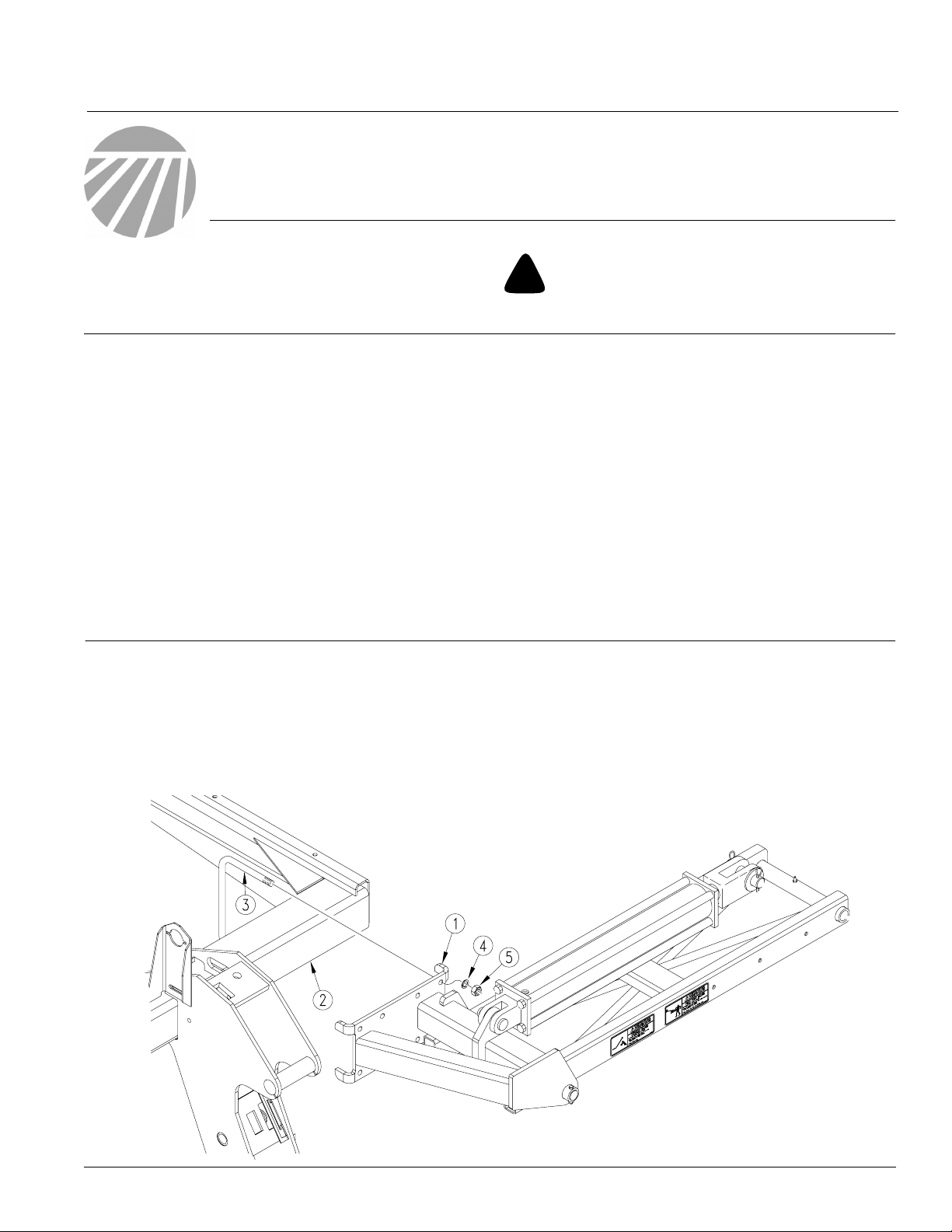
Refer to Figure 1
1. Lower drill into field position. Allow 25 feet on
each end of drill for marker assembly. Always assemble marker in unfolded position.
Manual Information
Refer to the 4000-3S operator’s manual for detailed
information on safely operating, adjusting, troubleshooting and maintaining the marker option. Refer
to the parts manual for part identification.
195-242M 4000-3S Operator’s Manual
195-242P 4000-3S Parts Manual
Before You Start
Beginning on page 12 is a detailed listing of parts included in the marker option package. Use this list to
inventory parts received.
2. Mount firstmarkersection (1)ondrill frame tube
(2) as shown. Secure with four 5/8" x
6" x 7 3/4" U-bolts (3), 5/8" lock washers (4) and
5/8" nuts (5).
NOTE: Mount the marker as far out on the frame as
possible.
© Copyright 2000 Printed
2/28/2006
Figure 1
First Marker Section Assembly
18923
113-728M
Marker Option
2
Great Plains Mfg., Inc.
Note: For drills with a fertilizer drive use the following instructions for mounting the first marker section to the right-hand side of the drill.
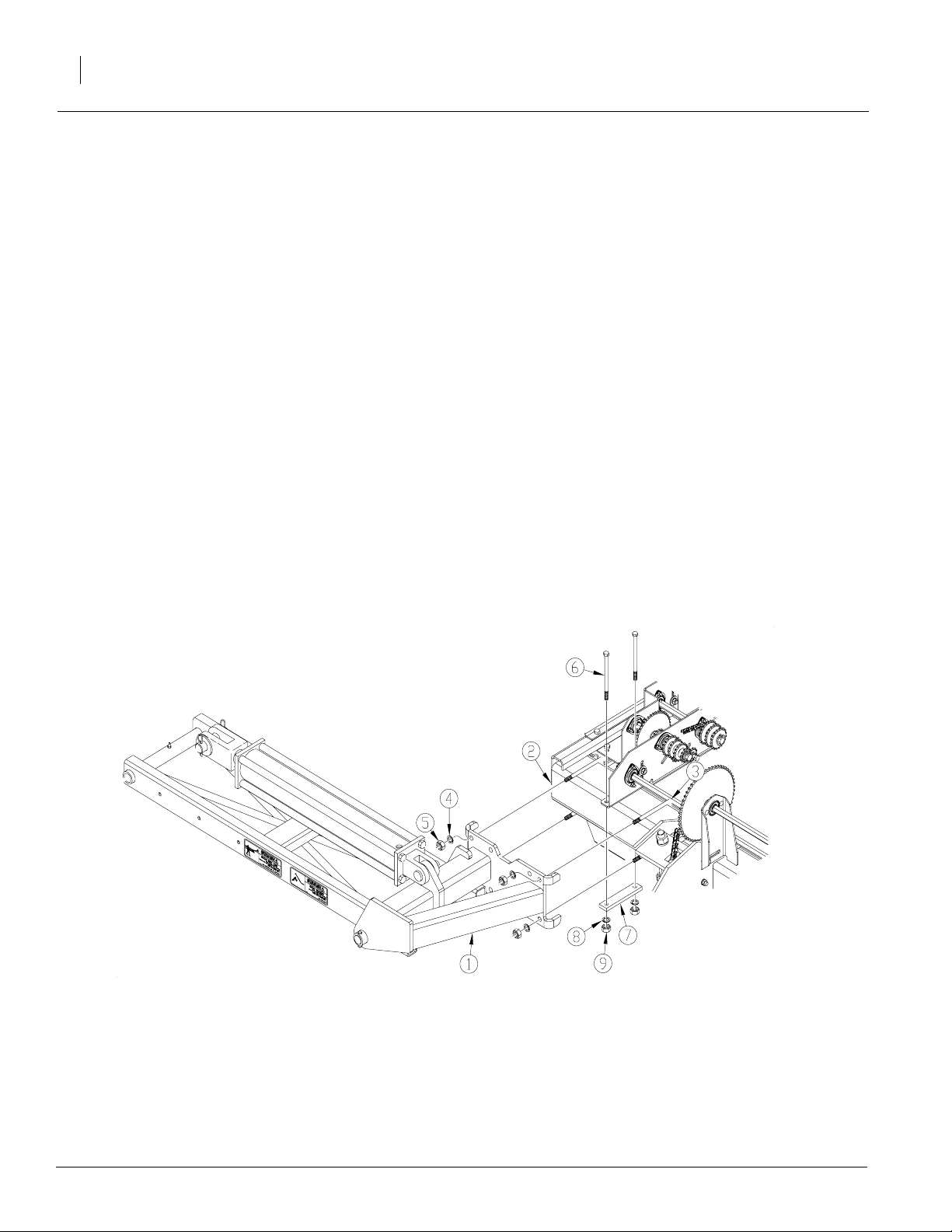
Refer to Figure 2
3. Remove the 1/2" U-bolt located on the front of
the fertilizer drivemounting plate. Keepthe lock
washers and nuts for later use.
4. Mount firstmarkersection (1)ondrill frame tube
(2) as shown. Secure with four 5/8" x
6" x 7 3/4" U-bolts (3), 5/8" lock washers (4) and
5/8" nuts (5).
NOTE: Mount the marker as far out on the frame
as possible.
5. Insert the two 1/2" x 7 1/2" bolts (6) through the
holes in the fertilizer drive mounting plate
where the U-bolt was removed.
6. Install the clamp bar (7) as shown and secure in
place with1/2" lockwashers (8)and 1/2" nuts (9)
removedinstep3.
21785
Figure 2
Right-hand First Marker Section with Fertilizer Drive
113-728M 2/28/2006
Great Plains Mfg., Inc.
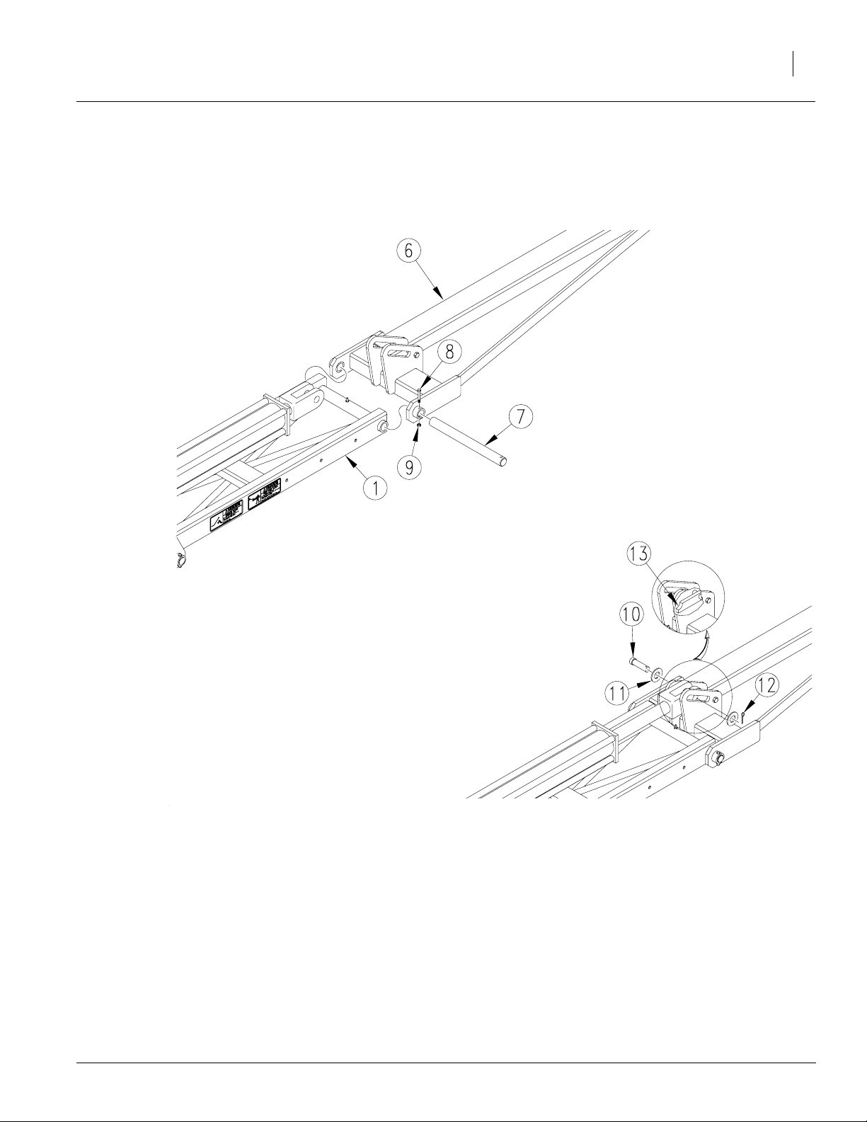
Refer to Figure 3
7. Assemble second marker section (6) to first
marker section (1) with 20 5/8" hinge pin (7). Fasten with5/16" x2 1/4" bolt (8) and 5/16" lock nut
(9).
Installation Instructions
3
Refer to Figure 4
8. Attach cylinder rod end to second marker section with clevis pin (10), flat washers (11) and
cotter pin (12).
NOTE: Make sure cylinder pin lock (13) is positioned
under cylinder clevis pin (10).
Figure 3
Second Marker Section to First Marker Section
18924
Figure 4
Cylinder Rod End to Second Marker Section
2/28/2006
113-728M
Marker Option
4
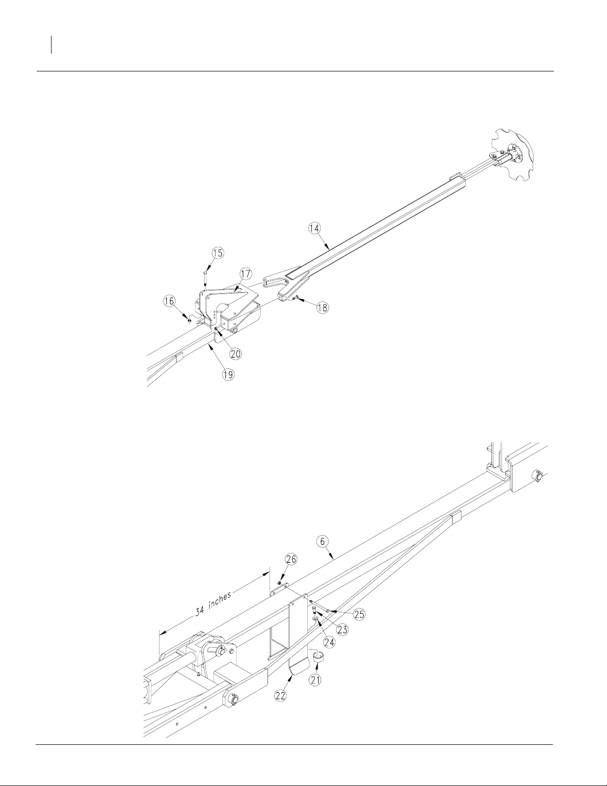
Refer to Figure 5
1. Assemble third marker section (14) to second
marker section (19) with 5/8" x 5" bolt(15) and5/
8" nut lock (16). After hinge bolt is installed, take
as much play out of the assembly by tightening
both hinge bolt (15) and middle clampbolt (17).
Stop tighteningboth boltswhen all the play has
been removed. Do not over tighten. Check to
make sure arm (14) can be rotated by hand. Secure opposite side with 7/16" x 2" bolt (17) and
7/16" nut hex lock (18).
NOTE: The 7/16" bolt (17) is the marker break away
bolt.
Great Plains Mfg., Inc.
Third Marker Section to Second Marker Section
Refer to Figure 6
2. Attach bumper (21) to marker rest bracket (22)
with a 1/2" x 3/4" bolt (23) and 1/2" lock washer
(24).
3. Attach marker rest bracket (22) to second marker section (6) with 3/8" x 6" bolts (25) and 3/8"
lock nuts (26).
NOTE: The 34 inch dimension shown is from the center of the hinge pin to the inner edge of rest bracket.
Figure 5
23204
18926
Figure 6
Marker Rest Bracket to Second Marker Section
113-728M 2/28/2006
Great Plains Mfg., Inc.
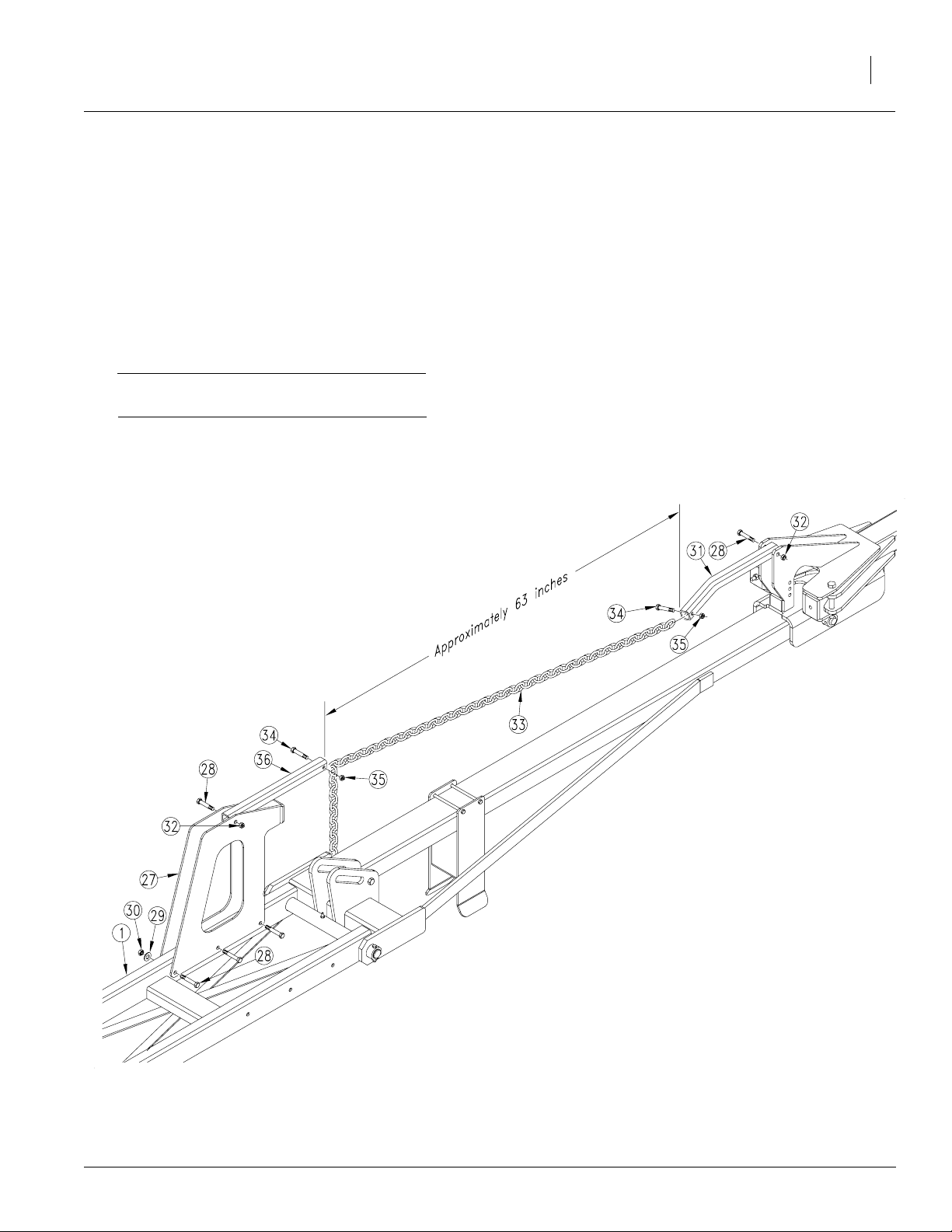
Refer to Figure 7
4. Attach transport brace (27) to first marker section (1) with 1/2" x 3 1/4" bolts (28) 1/2" lock
washers (29) and 1/2" lock nuts (30).
5. Assemble lift arms (31) and (36) to the transport
brace and second marker section as shown. Fasten with 1/2"x3 1/4" bolts(28)and 1/2" lock nuts
(32).
NOTE: Make sure thecurved end of arm (31)is facing
down down as shown.
IMPORTANT: Do not overtighten. The lift arms
must be able to swivel in their mounts.
6. Attach chain (33) to lift arms with 3/8" x 2 1/2"
bolts (34) and 3/8" lock nuts (35) to a length of
approximately 63" as shown.
NOTE: For adjustments for field operation, see drill
operator’s manual.
Installation Instructions
5
2/28/2006
NOTE: Cylinder removed
to show details.
21888
Figure 7
Transport Brace and Marker Chain Assembly
113-728M
Marker Option
6
Marker Carrier Assembly
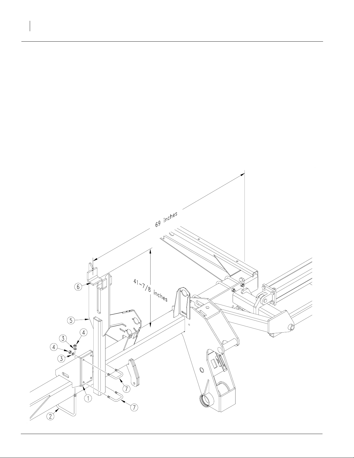
Refer to Figure 8
1. Attach marker carrier mount (1) to drill frame
with 1/2" x 6" x 7 1/4" U-bolts (2), 1/2" lock
washers (3) and 1/2" nuts (4). Center carrier
mount 69" from the outside end of drill frame.
2. U-bolt marker carrier (5) to carrier mount so
top ofsaddle surface (6) isabout 417/8" above
top of drill frame tube. Secure marker carrier
with 1/2" x 3" x 4" U-bolts (7), 1/2" lock washers
(3) and 1/2" nuts (4).
When folded, the second marker section should
rest in marker carrier saddle. After installing and
bleeding thehydraulics, marker carriermay require
further adjustment. Refer to Marker Adjustments in
the drill operator’s manual.
Great Plains Mfg., Inc.
Figure 8
Marker Carrier Installation
113-728M 2/28/2006
18932
 Loading...