

Great Plains 3SF45 Operator Manual

Operator’s Manual
36’ & 45’ 3-Section Solid Stand
Folding Drill
Manufacturing, Inc.
P.O. Box 5060 ● Salina, Kansas 67402-5060
Read the Operator’s manual entirely. When you see this symbol, the subsequent in-
!
structions and warnings are serious - follow without exception. Your life and the lives of
others depend on it!
© Copyright 1995 Printed
1999-04-08
Cover illustration may show optional equipment not supplied with standard unit.
170-062M

4/8/99
DEALER PREPARATION CHECK LIST
PREDELIVERY
Before delivering machine the following check list should be completed. Use this Owner’s Manual as a guide.
1. ❑ Assembly completed.
2. ❑ Fluids added & checked.
3. ❑ All grease fittings lubricated. Refer to "Maintenance & Lubrication" section.
4. ❑ Check & tighten all hardware. Refer to "Nut & Bolt Torquing Chart".
5. ❑ All decals are in place & readable. See "Decal Placement" section.
6. ❑ All safety shields or guards are in place.
7. ❑ Overall conditions good {i.e. paint, welds}.
This check list is to remain in Owner’s Manual.
0-1
It is the responsibility of the dealer to complete the procedures listed above BEFORE delivery of this
machine to the customer.
DELIVERY
Review this Owner’s Manual with the customer. Explain the following & check off as completed.
1. ❑ Safety procedures for operation & service.
2. ❑ Basic operating & adjustments.
3. ❑ Daily & periodic maintenance & lubrication. Refer to "Maintenance & Lubrication" section.
4. ❑ Correct lubricants & usage.
5. ❑ Great Plains parts & service.
6. ❑ Record serial number. See "Introduction" on next page.
7. ❑ Remind customer that all decals should remain in place & readable. See "DecalPlacement" section & con-
tact dealership for replacements when needed.
8. ❑ Remind customer that ALL safety shields & guards are not to be removed.
9. ❑ Give customer this Owner’s Manual & encourage them to read it.
170-062M
Effective 4/8/99
170-062M

0-2
Your Great Plains 3-Section Solid Stand Folding Drill is designed to give you many years of dependable service. This manual has been prepared to instruct you in the safe and efficient operation of
this machine. Read and study it thoroughly. Follow all instructions and service procedures carefully.
The parts on your 3-Section Solid Stand Folding Drill have been specially designed and should only
be replaced with genuine Great Plains parts. Therefore; should your drill require replacements
parts, purchase them from your Great Plains Dealer.
Space has been provided below for you to record your model number and serial number of your drill.
Be sure to bring this information with you to your dealer when ordering parts or attachments for your
drill.
The following signal symbol and words should be clearly understood! When seen in this manual or
on your equipment, this symbol and words will alert you to the seriousness of a situation. They
should not be ignored or taken lightly.
INTRODUCTION
4/8/99
!
The SAFETY ALERT SYMBOL indicates that there is a potential hazard to personal safety
involved and extra safety precautions must be taken. When you see this symbol, be alert and carefully read the message that follows it. In addition to design and configuration of equipment; hazard
control and accident prevention are dependent upon the awareness, concern, prudence and proper
training of personnel involved in the operation, transport, maintenance and storage of equipment.
DANGER: Indicates an imminently hazardous situation which, if not avoided, will result in death
or serious injury This signal word is limited to the most extreme situations.
WARNING: Indicates a potentially hazardous situation which, if not avoided, could result in
death or serious injury.
CAUTION: Indicates a potentially hazardous situation which, if not avoided, mayresult in minor
or moderate injury. It may also be used to alert against unsafe practices.
SERIAL NUMBER ___________________
MODEL NUMBER ___________________
DATE PURCHASED _________________
170-062M

4/8/99
TABLE OF CONTENTS
Dealer Preparation Check List ................................................................................. 0-1
Introduction.............................................................................................................. 0-2
Table Of Contents ................................................................................................... 0-3
Section 1 Safety
Safety Rules ............................................................................................................ 1-1
Safety Decals .......................................................................................................... 1-2
Safety Decal Placement .......................................................................................... 1-3
Decal Placement ..................................................................................................... 1-4
Nut & Bolt Torquing Chart ....................................................................................... 1-5
Tire Inflation Chart ................................................................................................... 1-5
Section 2 Assembly
Assembly Instructions & Set Up .............................................................................. 2-1
Tractor Requirements .............................................................................................. 2-3
Tractor Draw Bar Hook-up ...................................................................................... 2-3
Tractor Hydraulic Hook-up ...................................................................................... 2-4
Bleeding The Lifting Hydraulic Systems .................................................................. 2-4
Bleeding The Folding Hydraulic Systems ................................................................ 2-5
Section 3 Basic
Basic Drill Operating Procedures Folding ........................................................... 3-1
Lifting.............................................................. 3-2
Unfolding ........................................................ 3-3
Transporting ............................................................................................................ 3-4
Parking .................................................................................................................... 3-6
0-3
Section 4 Drives
Drive & Metering System Adjustments .................................................................... 4-1
Clutch Shaft & Miter Gear Alignment ...................................................................... 4-2
Section 5 Seeds
Seeding Adjustments .............................................................................................. 5-1
Solid Stand Folding Drill Seed Rate Charts ............................................................. 5-3
Section 6 Depth
Planting Depth Adjustments Overview ........................................................ 6-1
Press Wheel Opener Linkage ........................ 6-2
Disk Opener Spring Pressure Setting ............ 6-2
Press Wheel Angle......................................... 6-2
Center Box Gauge Wheel ............................. 6-3
Leveling the Drill............................................. 6-4
Box Alignment Adjustments ..................................................................................... 6-5
Floating Top Link...................................................................................................... 6-6
Section 7 Preparation
Drill Preparation ....................................................................................................... 7-1
Operating Check List ............................................................................................... 7-2
Section 8 Maintenance
Maintenance ............................................................................................................ 8-1
Maintenance & Lubrication ...................................................................................... 8-1
Storage .................................................................................................................... 8-2
Section 9 Trouble Shooting
Trouble Shooting ..................................................................................................... 9-1
Specifications .......................................................................................................... 9-3
Warranty .................................................................................................................. 9-4
170-062M

0-4
4/8/99
170-062M

4/8/99
0-5
170-062M

4/8/99
SAFETY RULES
! !
The safe operation of machinery is a big concern to farmers and manufacturers. We have designed
our 3-Section Solid Stand Folding Drill with many built-in safety features. However, no one should
operate this drill before carefully reading this Owner’s Manual.
1. NEVER permit anyone to ride on or walk beside the drill when moving.
2. NEVER permit anyone to ride on tractor when the drill is being moved.
3. NEVER allow anyone to be near the drill when performing operating functions with the drill or
tractor.
4. NEVER load the drill without being hooked up to a tractor.
5. Extra care should be taken when transporting with seed in the box.
6. ALWAYS securely connect the hitch safety chain to the tractor before transporting the drill.
7. Reduce speed of the tractor when transporting over uneven or rough terrain. Avoid all chuck
holes and washboard areas in roads.
1-1
8. Reduce speed of the tractor when transporting over hills or steep slopes. NEVER transport
drill faster than 20 miles per hour.
9. When in transport, use accessory lights and devices for adequate warning to operators of other
vehicles and use safety hitch chain. Comply with all Federal, State and Local laws when traveling on public roads.
10. Use "Slow Moving Vehicle" emblem for warning vehicles approaching from the rear.
11. When transporting, remember the drill is wider than your tractor and extreme care must be taken to allow for safe clearance.
12. NEVER back up when openers are in the ground.
13. ALWAYS set the drill in field position BEFORE lubrication, making adjustments, or servicing.
14. DO NOT lubricate, adjust or repair the drill while it is in operation.
15. DO NOT permit smoking, sparks, or an open flame where combustible lubricants or liquids are
being used.
16. When using treated seed, avoid direct contact with the seed.
17. When using compressed air to clean the drill, wear safety glasses.
18. NEVER unhook drill from tractor when negative tongue weight is present.
19.
!
CAUTION! Escaping fluid under pressure can have sufficient force to penetrate the
skin. Check all hydraulic lines and hoses BEFORE applying pressure. Fluid escaping from a
very small hole can be almost invisible. Use paper or cardboard, NOT BODY PARTS, to check
for suspected leaks. If injured, seek medical assistance from a doctor that is familiar with this
type of injury. Foreign fluids in the tissue must be surgically removed within a few hours or gangrene will result.
170-062M

1-2
LIFT CYLINDERS
OPERATING INSTRUCTIONS
THIS MACHINE IS EQUIPPED WITH REPHASING MASTER SLAVE
LIFT CYLINDERS. THESE CYLINDERS MAY AFTER A PERIOD OF
TIME GET OUT OF TIME OR PHASE. THE EFFECTS OF THIS CAN
BE SEEN WHEN ONE SECTION IS RUNNING TOO LOW OR TOO
HIGH BECAUSE ITS LIFT CYLINDER IS EITHER OVEREXTENDED
OR OVERRETRACTED COMPARED TO THE OTHER LIFT CYLINDERS. TO REPHASE THE CYLINDERS, RAISE THE IMPLEMENT
COMPLETELY UP AND HOLD THE TRACTOR HYDRAULIC LEVER
ON FOR A FEW SECONDS TO GIVE THE CYLINDERS TIME TO
REPHASE. THIS SHOULD BE DONE EACH TIME THE MACHINE IS
RAISED OUT OF THE GROUND. MOMENTARILY REVERSING THE
HYDRAULIC LEVER IMMEDIATELY AFTER REPHASING TO ALLOW
THE CYLINDERS TO RETRACT ABOUT 1/2" WILL HELP IN MAINTAINING A LEVEL IMPLEMENT.
WARNING
!
818-043C
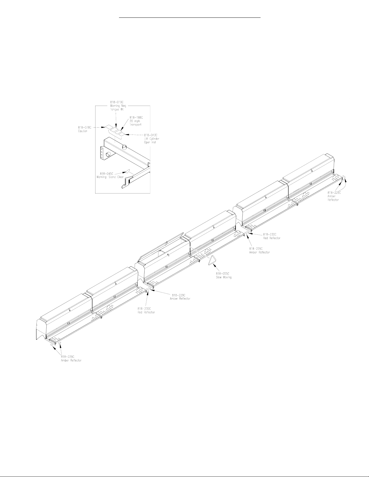
SAFETY DECALS
!
TRANSPORT SPEED
EXCEEDING 20 MPH MAY RESULT IN LOSS OF VEHICLE
CONTROL AND / OR IMPLEMENT DAMAGE
4/8/99
WARNING
20 MPH MAX.
818-188C
STAND CLEAR WHILE FOLDING,
UNFOLDING, RAISING, OR
LOWERING IMPLEMENT.
818-045C
WARNING
! !
SAFETY HAZARD
USE EXTREME CAUTION
WHEN UNHITCHING IMPLEMENT
FROM TRACTOR.
Negative tongue weight may cause
immediate elevation of tongue resulting
in damage or personal injury.
818-019C
Reflector - Red
818-230C
Reflector - Amber
818-229C
Slow Moving Vehicle
818-055C
CAUTION
!
- - Read Owner’s Manual Before Operating Drill
- - Stand Clear When Folding And Unfolding Drill
- - Stand Clear When Raising And Lowering Drill
- - Keep All Safety Shields And Devices
In Place
- - Keep Hands And Clothing Away From
Moving Chains And Sprockets
- - Never Ride On Drill
- - Before Transpor ting, Be Sure Transport Lock Pins Are In Transport Position And Folded Boxes Are Locked In
- - Hitch Drill To Tractor Before Folding,
Unfolding Or Filling With Seed
- - Always Lower Or Properly Support
Drill Before Servicing
- - Escaping Hydraulic Fluid Can Cause
Serious Injury.
818-078C
--IMPORTANT--
* Your 3-Section Solid Stand Folding Drill comes equipped with all safety decals in place.
* Always keep safety decals clean and legible.
* Replace all damaged or missing safety decals. To order new safety decals go to your Great
Plains Dealer and reference part numbers as shown on pages 1-3 & 1-4.
* To install new safety decals:
A) Clean the area the decal is to be placed. (Refer to pages 1-3 & 1-4.)
B) Peel backing from decal and press firmly onto clean surface.
170-062M
4/8/99
SAFETY DECAL PLACEMENT {170-063A}
Includes ALL SAFETY Decals As Shown Below.
1-3
10229
170-062M
1-4
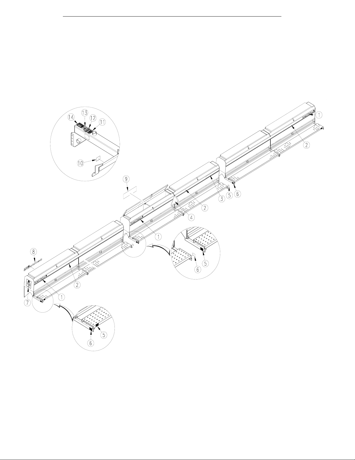
DECAL PLACEMENT {170-064A 36’ DRILL} {170-065A 45’ DRILL}
Includes ALL Decals As Shown Below.
4/8/99
10228
170-062M

4/8/99
NUT & BOLT TORQUING CHART
This chart is based on torque requirements in foot pounds for grade 5 bolts.
BOLT MINIMUM MAXIMUM BOLT MINIMUM MAXIMUM
DIAMETER TORQUE TORQUE DIAMETER TORQUE TORQUE
1/4” 9 11 3/4” 270 324
5/16” 17 20 7/8” 400 480
3/8” 35 42 1" 580 696
7/16” 54 64 1 1/8” 800 880
1/2” 80 96 1 1/4” 1120 1240
9/16” 110 132 1 3/8” 1460 1680
5/8” 150 180 1 1/2” 1940 2200
NOTE: Torque requirements listed above do not apply to self-locking nuts. For self-locking nuts increase the torque
requirements listed above by 15%.
1-5
TIRE INFLATION CHART
TIRE SIZE INFLATION PSI
7.50 x 20" 4 Ply Drill Rib 28
9.0 x 24" 8 Ply Rib Implement 40
9.5L x 15" 6 Ply Rib Implement 32
9.5L x 15" 8 Ply Rib Implement 44
9.5L x 15" 12 Ply Rib Implement 60
11L x 15" 6 Ply Rib Implement 28
11L x 15" 12 Ply Rib Implement 52
12.5L x 15" 8 Ply Rib Implement 36
12.5L x 15" 10 Ply Rib Implement 44
16.5L x 16.1" 10 Ply Rib Implement 36
170-062M

1-6
4/8/99
170-062M

4/8/99
ASSEMBLY INSTRUCTIONS & SET UP
BEFORE YOU START
2-1
Read and understand the owners manual for your drill. A
basic understanding of how the drill works will aid in the
assembly and setup of your drill.
Before attempting to assemble the drill use the following
as a check list. Having all the needed parts and equipment readily at hand will speed up your assembly task
and will make the job as safe as possible.
❑Check for all major frame components
❑Check for fasteners and pins that were shipped with the
drill. NOTE: All hardware coming from the factory has
been installed in the location where it will be used. If a part
or fastener is temporarily removed for assembly reasons,
remember where it goes.Keep the parts separated.
❑If a pin, bolt or other part has been removed, and you
are unsure where it is used, use the parts section of this
manual to identify it. Be sure the part gets used in the correct location. By double checking while you assemble,
you will lessen the chance of using a bolt incorrectly that
may be needed later.
❑Have a fork lift or loader along with chains and safety
stands that are sized for the job ready for the assembly
task.
❑Have a tractor with remote hydraulics ready to attach to
the tongue. The tongue must be anchored to a large
enough tractor to overcome the negative tongue weight
that will be present when the boxes are attached to the
frame. The hydraulics will aid in raising and lowering the
drill to align pins and bolts during assembly.
!
CAUTION! Be familiar with the term NEGA-
TIVE TONGUE WEIGHT. Be aware of the special precautions you should take when working with an
implement that can develope Negative Tongue
Weight.
❑Have a minimum of 2 people at hand while assembling
the drill.
ASSEMBLING THE DRILL
Read and understand the previous section BEFORE YOU START.
1. Read "Safety Rules", on page 1-1, in this manual before assembling drill.
2. Mount all gauge wheel tire assemblies to drills.
3. With the tool bars supported parallel to tongue, position center box behind transport frame and hook up box, lower
3-Point arms first, then the top link. The d ill may need to be tipped forward to attach top link or tongue raised to
make this connection.
4. Line up right drill with center drill with approximately 4 1/2" between ends of boxes. Swing tool bar open and support
while hooking up lower 3-Point arms first; n xt the upper hitch by raising or lowering tool bar.
5. Repeat operation 5 for left drill hook up.
6. To line up drills for proper pull bar length adjustment and hook up, tape or have someone hold a string on the back
side of the left end of the center drill; extend out across the center drill and to the outboard end of right drill 6 1/2"
forward from the string to the back of the right drill. With the pull bar slide in the back position on the tongue adjust
the right pull bar and hook up to slide and tool bar brace.
7. For lining up and adjusting pull bar for left drill do the same as listed operation 7 except tape or have someone hold
a string on the back side of the right end of the center drill and extend out across the center drill and to the outboard
end of the left drill.
8. Hook up lift cylinder hydraulic hoses to gauge wheel cylinders. To do this you run hydraulic hoses from tool bars
down to and on top of the 2 x 2 tube on the wing drill frame that the front of the double disk openers attach to. The
longest hose from the tool bar attaches to the rod end port of the outboard cylinders. The hoses at each gauge
wheel should be run through the opening in the drill frame and between the gauge wheel mount plates. The jumper
hose from the master cylinder mounted inboard on each wing drill should already be installed from the rod end port
to the base end port of the slave cylinder at the outboard gauge wheel.
9. Repeat operation 9 on the left wing drill.
170-062M

2-2
ASSEMBLY INSTRUCTIONS & SET UP (CON’T.)
ASSEMBLING THE DRILL (Con’t.)
4/8/99
10. To hook up lift hydraulics to the center drill, route hoses from out of the back of the tongue. Use the same
route as used on the wing drills and attach one hose
to the base end port of the master cylinder and the rod
end port of the slave cylinder. The jumper hose should
already be installed.
11. Hook tractor up to the tongue and plug hydraulic connectors into the tractor. With tractor running at an idle
speed charge the drill hydraulic system. {Be sure your
tractor has plenty of hydraulic fluid. This system re
quires approximately 6 gallons.} When your drill frame
raises for the firs time, one lift cylinder will extend fully
before the other one begins to move. Once the firs
cylinder is fully extended continue to hold your tractor
valve in the same position for at least 60 seconds after
the second lift cylinder has fully extended. The reason
for the unevenness of raising for the first time is be
cause your drill is equipped with master and slave
rephasing cylinders. Raise and lower the frame several times to be sure there is no binding or problems
with your lift system. Refer to "Tractor Draw Bar
Hookup" on page 2-3, and "Tractor Hydraulic
Hookup" on page 2-4.
12. Check to see that all nuts are tightened. See the "Nut
& Bolt Torquing Chart" on page 1-5 for torque spec-
ification .
170-062M
 Loading...