

Page 1

Manufacturing, Inc.
www.greatplainsmfg.com
Seed, Small Seeds and Fertilizer
Rate Charts for the 3S-4010HD
3-Section 40-Foot Heavy Duty Drill
The following pages are to assist in the proper setting of seeding and fertilizer rates for the 3S-4010HD and 3S-4010HDF.
To assure the most accurate seeding rates it is recommended that the drill be calibrated for the desired
seed at the time of planting.
© Copyright 2009 Printed 01/29/2009 196-522B
Page 2

Great Plains Mfg., Inc.
Table of Contents
Introduction ................................................................1
Drill models covered by this manual.............................1
Document Family .........................................................1
Setting Main Box Seed Rate......................................2
Setting Drive Type........................................................3
Changing Drive Type................................................3
Main Box Seed Rate Handle........................................4
Position Seed Cup Doors.............................................4
Main Box Seed Rate Calibration..................................5
Reading a Seed Rate Chart.........................................7
Main Box Seed Rate Charts.........................................8
Alfalfa or Rape.................................................................. 8
Barley (1 of 3) ................................................................... 8
Buckwheat ........................................................................ 8
Buffalograss (1 of 4).......................................................... 9
Flax or Sudan.................................................................... 9
Millet.................................................................................. 9
Milo ................................................................................. 10
Peas................................................................................ 10
Pinto Beans..................................................................... 10
Rice, Short Grain (1 of 2)................................................ 10
Rice, Long Grain (1 of 4)................................................. 11
Rye.................................................................................. 11
Soybeans (1 of 4)............................................................ 12
Sunflower........................................................................ 12
Wheat (1 of 2)................................................................. 13
Wheatgrass..................................................................... 13
Setting Fertilizer Rate ..............................................14
Adjusting for Density ..................................................14
Setting Fertilizer Drive Range ....................................15
Range: Front Sprocket .......................................15
Range: Rear Sprocket........................................15
Changing Range Sprockets....................................15
Setting Fertilizer Transmission...................................16
Fertilizer Rate Calibration...........................................17
Fertilizer Rate Charts, U.S. Customary Units.............19
Fertilizer Rate, 7.5in Row Spacing.........................19
Fertilizer Rate, lbs/ac, 10in Row Spacing...............20
Small Seeds Rate .....................................................21
Small Seeds Rate Calibration ....................................21
Small Seeds Rate Charts, U.S. Customary Units ......23
Alfalfa, Red Alsike, Crimson Clover................................ 23
Kentucky Bluegrass,
Fescue, Annual Rye Grass..........................................23
Bermuda, Red Top, Lespedeza Unhulled,
Sercia, Sand, Weeping Love Grass ............................23
Red & Sweet Clover, Lespedeza Hulled..........................23
Orchard Grass .................................................................23
Millet, Reed Canary .........................................................23
Ladino Clover, Canary Grass,
Timothy, Canola ..........................................................24
Birdsfoot, Trefoil, Sudan ..................................................24
Appendix...................................................................25
Main Seed Box Rate Charts, Metric...........................25
Alfalfa or Rape.................................................................25
Barley (1 of 3) ..................................................................25
Buckwheat .......................................................................25
Buffalograss (1 of 4).........................................................26
Flax or Sudan...................................................................26
Millet.................................................................................26
Milo ..................................................................................27
Peas.................................................................................27
Pinto Beans......................................................................27
Rice, Short Grain (1 of 2).................................................27
Rice, Long Grain (1 of 4)..................................................28
Rye...................................................................................28
Soybeans (1 of 4).............................................................29
Sunflower.........................................................................29
Wheat (1 of 2)..................................................................30
Wheatgrass......................................................................30
Fertilizer Rate Charts, Metric.....................................31
Fertilizer Rate, 19.2cm Row Spacing.....................31
Fertilizer Rate, 25.4cm Row Spacing.....................32
Small Seeds Rate Charts, Metric...............................33
Alfalfa, Red Alsike, Crimson Clover.................................33
Kentucky Bluegrass,
Fescue, Annual Rye Grass..........................................33
Bermuda, Red Top, Lespedeza Unhulled,
Sercia, Sand, Weeping Love Grass ............................33
Red & Sweet Clover, Lespedeza Hulled..........................33
Orchard Grass .................................................................33
Millet, Reed Canary .........................................................34
Ladino Clover, Canary Grass,
Timothy, Canola ..........................................................34
Birdsfoot, Trefoil, Sudan ..................................................34
© Copyright 2000, 2006, 2007, 2008, 2009 All rights Reserved
GreatPlainsManufacturing,Inc. providesthis publication“as is” without warranty ofany kind,either expressedor implied.While ev eryprecaution has been takenin the preparation
of this manual, Great Plains Manufacturing,Inc. assumes noresponsibility for errors or omissions. Neither isany liability assumed for damages resulting from the use of theinformation contained herein. Great Plains Manufacturing, Inc. reserves the right to reviseand improve its products as it sees fit.This publication describes the state of this product at
the timeof its publication,and may notreflect the productin the future.
The followingare trademarks of Great Plains Mfg.,Inc.: Application Systems,Ausherman, Land Pride,Great Plains
All otherbrands and productnames are trademarks or registered trademarks oftheir respective holders.
01/29/2009 196-522B
Great PlainsManufacturing, Incorporated Trademarks
Printed in the United States of America.
Page 3

Great Plains Mfg., Inc.
Introduction
This manual is your guide to planter adjustments for
achieving specific seed population and fertilizer density
targets.
Although some setup/adjustment material herein is
repeated from the drill Operator’s Manual, you need to
be thoroughly familiar with drill operations and adjustments before applying this Seed Rate manual and its
table data.
Drill models covered by this manual
Seed-only models:
3S4010HD-4810 48 row 10in (25cm)
3S4010HD-6475 64 row 7.5in (19cm)
Fertilizer models:
3S4010HDF-4810 48 row 10in (25cm)
3S4010HDF-6475 64 row 7.5in (19cm)
The rate charts are independent of drill width and row
spacing.
1
Document Family
196-522M Owner’s Manual
196-522P Parts Manual
196-522B Seed Rate Manual (this document)
01/29/2009 196-522B
Page 4
3S-4010HD and 3S-4010HDF
2
Setting Main Box Seed Rate
Accurately obtaining the desired seed population
requires four steps:
1. Setting Drive Type sprockets (from chart)
2. Setting initial Seed Rate Handle (from chart)
3. Positioning Seed Cup Door (by seed type)
4. Calibration: checking actual seeding rate
Seed rate charts, and rate setting/calibratinginformation,
is included in both the Operator’s Manual, and this separate Seed Rate Manual. The Seed Rate manual is normally stored in a weatherproof holder on the drill, for field
reference. The charts list proper sprocket pairings and
seed-rate-handle settings for various seeds and seeding
rates.
The seed-rate charts are based on cleaned, untreated
seed of average size and test weight. The charts are
based on 18-22.5 (445/65 D22.5) NHS 16-Ply tires,
inflated to factory specification. Many factors will affect
seeding rates including foreign material, seed treatment,
seed size, seed weight, field conditions, tire pressure
and test weight. Minor adjustments are commonly
required. Set and check the seeding rate using the procedures below, then readjust the rate as necessary.
Great Plains Mfg., Inc.
196-522B 01/29/2009
Page 5
Great Plains Mfg., Inc.
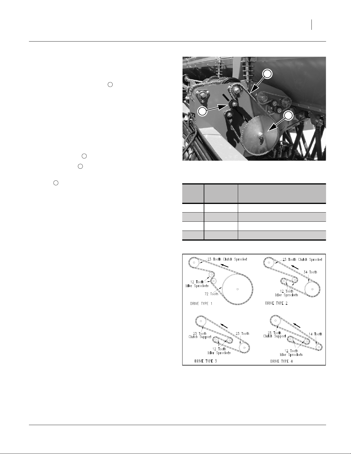
Setting Drive Type
3
Refer to Figure1
Drive Type is determined by the size (tooth count) of a
sprocket on the seed jackshaft of each drill section. If
1
changed, the sprocket must be set identically on each
drill section (3 locations).
For correct Drive Type, refer to seed-rate charts beginning on page 8. The charts list Drive Types as 1, 2, 3 or
4. Each Drive Type corresponds to a specific sized
sprocket, per the table and Figure 2 at right.
Changing Drive Type
Refer to Figure1
1. Loosen top idler and slide idler up.
2. Lift drive chain off sprocket currently in use.
3. Remove lynch pins and rearrange sprockets on jack-
1
shaft .
Note: Sprockets are stored on both ends of jackshaft (1
alternate sprocket under the Drive Type sprocket,
and 2 alternates (plus Fertilizer alternates) on the
far end of the shaft.
Do not mix Drive Type sprocketswith Fertilizer
sprockets on the vertical storage trees.
2
3
3
2
Figure 1
Drive Type 1 Configured
Drive
Type
Sprocket Relative Speed
1 72 Tooth Slowest
2 34 Tooth 2.12 times faster than Type 1
3 23 Tooth 3.13 times faster than Type 1
4 14 Tooth 5.14 times faster than Type 1
1
28178
4. Sprocketcorresponding to the required Drive Typeis
remounted as the outermost (, with larger side of
raised hub awayfrom pin, keeping teeth aligned with
driving sprocket at top). Make sure all 4 sprockets
are accounted for when remounting them on the
shaft.
5. Remount drive chain on the outermost (Drive Type)
sprocket.
6. Re-engage top idler and secure. Allow
1
⁄
in (1.3cm)
2
slack in longest (top) span of chain.
7. Set the same Drive Type on all three drill sections.
Figure 2
Drive Type Chain Routing
18839
01/29/2009 196-522B
Page 6
3S-4010HD and 3S-4010HDF
4
Main Box Seed Rate Handle
There are main box seed rate handles for each section of
the drill (3 handles total). Generally, all need to be set
identically, and you need to calibrate only one section.
The seed rate handle controls the percent engagement
of the seed sprocket in each seed cup. The initial setting
of the handle is given by the Seed Rate Chart.
Note: Youcantemporarily stop seed flow to a drill section
by setting a handle to zero.
To set a handle:
1. Loosen wing nut under handle.
2. Move indicator to a rate about 10 higher than the
suggested rate from Seed Rate Chart. Then move
handle back to chart rate.
3. Tighten wing nut.
1
1
Fi S
1
Figure 3
Seed Rate Handle
Great Plains Mfg., Inc.
2
28181
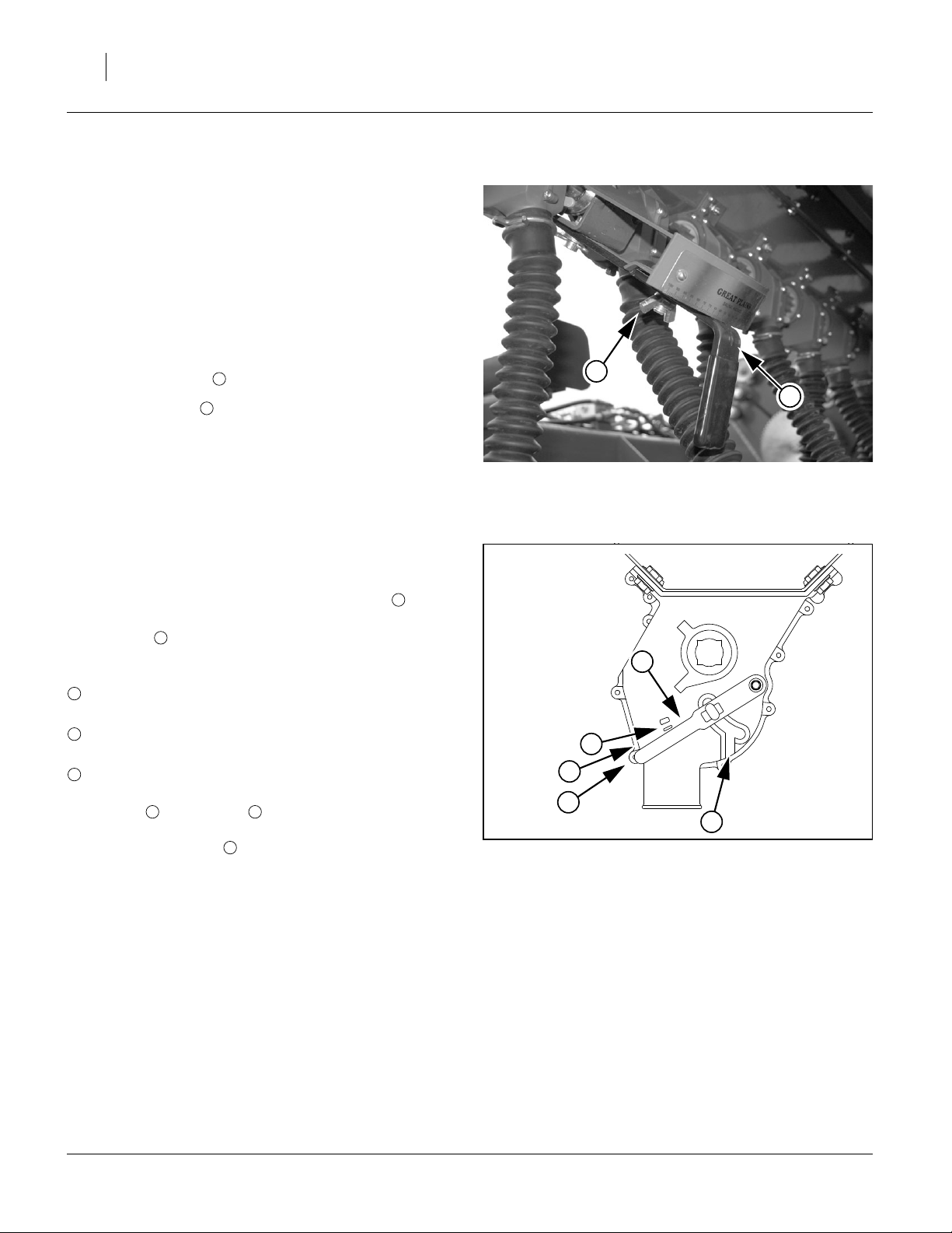
Position Seed Cup Doors
Refer to Figure4,
which depicts the seed cup door handle in position .
At each main seed box seed tube, adjust the seed cup
door handle for the seed size.
4
The handle has three normal operating position detents:
(top detent) is for the smallest seeds.
1
Use it for wheat and similar small seeds.
(middle detent) is for larger seeds.
2
Use it for soybeans and similar larger seeds.
(bottom detent) is for oversize or fragile seeds.
3
If you experience excessive cracking with
setting , use setting .
Note: Handle position is used for cleanout, not plant-
2 3
5
ing.Ifset to thispositionwithseedloaded, itmaybe
difficult to reset it to a normal operating position.
3
4
1
2
3
Figure 4
Seed Cup Door Handle
5
26211
196-522B 01/29/2009
Page 7
Great Plains Mfg., Inc.
Main Box Seed Rate Calibration
Differences will exist between the tested seed and field
conditions used to generate the Seed Rate Charts, and
your seed and conditions. To accurately achieve your target population, Great Plains recommends calibrating.
Perform the calibration with the drill unfolded and lowered to field position. Turn off or disconnect power to the
clutches.
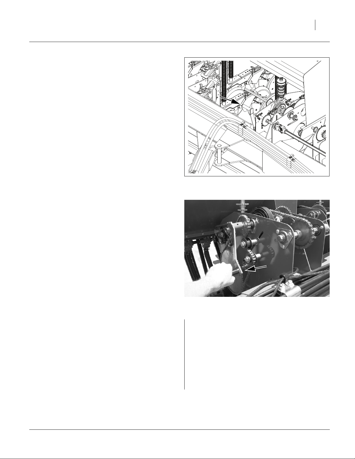
Refer to Figure5
1. Lower drill. Set MASTER switch on clutch control
box to OFF position.
2. Remove the calibration crank from its storage location on the right section drive. Store the pin on the
stob.
3. On the right drill section, if fertilizer rate is not also
being calibrated at the same time, and fertilizer is
present, remove the fertilizer drive chain.
Figure 5
Stored Calibration Crank
5
29240
Refer to Figure6
4. Install cr
ank on clutch shaft of right section.
Crank rotation is clockwise, facing to drill left.
5. Use crank to turn clutch shaft and check that the
drives and seed cups are engaged, working properly
and free from foreign material. If not already done,
set the Drive Type, Seed Rate Handle and Seed Cup
Doors across the drill.
ll C
Figure 6
Installed Calibration Crank
For example:
on a drill with a row spacing of:
7.5 inches
and a row count of:
64
you desire to plant barley at:
50 pounds per acre
which, from the Barley Drive Type 2 chart,
is an initial Seed Rate Handle scale setting of:
40
28180
01/29/2009 196-522B
Page 8

3S-4010HD and 3S-4010HDF
6
Great Plains Mfg., Inc.
6. Record the weight of one to three empty containers
collectively large enough to hold seed metered for
6% of one acre or hectare.
7. Place several pounds or kg of seed over three seed
cups on the outside end of the right drill box. Pull
lower end seed hoses off of these drops at the
opener end.
8. Turn the calibration crank several times to fill seed
cups. Turn until seed drops to ground from each
hose.
9. Place empty container(s) under the three hoses to
gather metered seed.
10. Turn crank for one acre (45.1 rotations) or one hectare (111.4 rotations). While turning, check that cups
have ample seed coming into them.
11. Weigh metered seed. Subtract initial weight of container(s).
NetWeight GrossWeight ContainerWeights–=
12. Divide the net seed weight by three. Multiply by number of openers on your drill to determine the total of
pounds-per-acre seeded.
NetWeight
MeasuredRate
------------------------3
OpenerCount×=
For example:
three empty 8 oz. containers weigh a total of:
1.5 lb.
For example: the containers weighed a total of 4.0 lb
after test:
2.7 lb net
2.7 4.2 1.5–=
For example:
on the 64-row 7.5in drill:
57.5 lb/ac
2.7
57.5
-----3
64×=
13. The Seed Rate Handle scale is a percentage of
meter opening, and is quite linear near scale center.
Calculate a new scale setting based on the test.
TargetRate
NewScale
--------------------------------- MeasuredRate
OldScale×=
Note: You may want to repeat calibration procedure if
your results varied greatly from the Seed Rate
Chart, or if you must operate near the ends of the
Seed Rate handle scale (0-20 or 90-100).
14. Set the center and left drill sections to match the
now-calibrated right section.
15. With calibration complete, Reinstall fertilizer chain (if
removed) and reconnect seed hoses.
When drilling, check seeding rate by noting acres drilled,
amount of seed added to drill and seed level in drill box.
If you are seeding more or less than desired, adjust rate
slightly to compensate for field conditions.
For example:
the target rate was 50 lb/ac, and the initial scale 40:
the new scale setting is:
35
50
---------
35
57.5
40×=
196-522B 01/29/2009
Page 9
Great Plains Mfg., Inc.
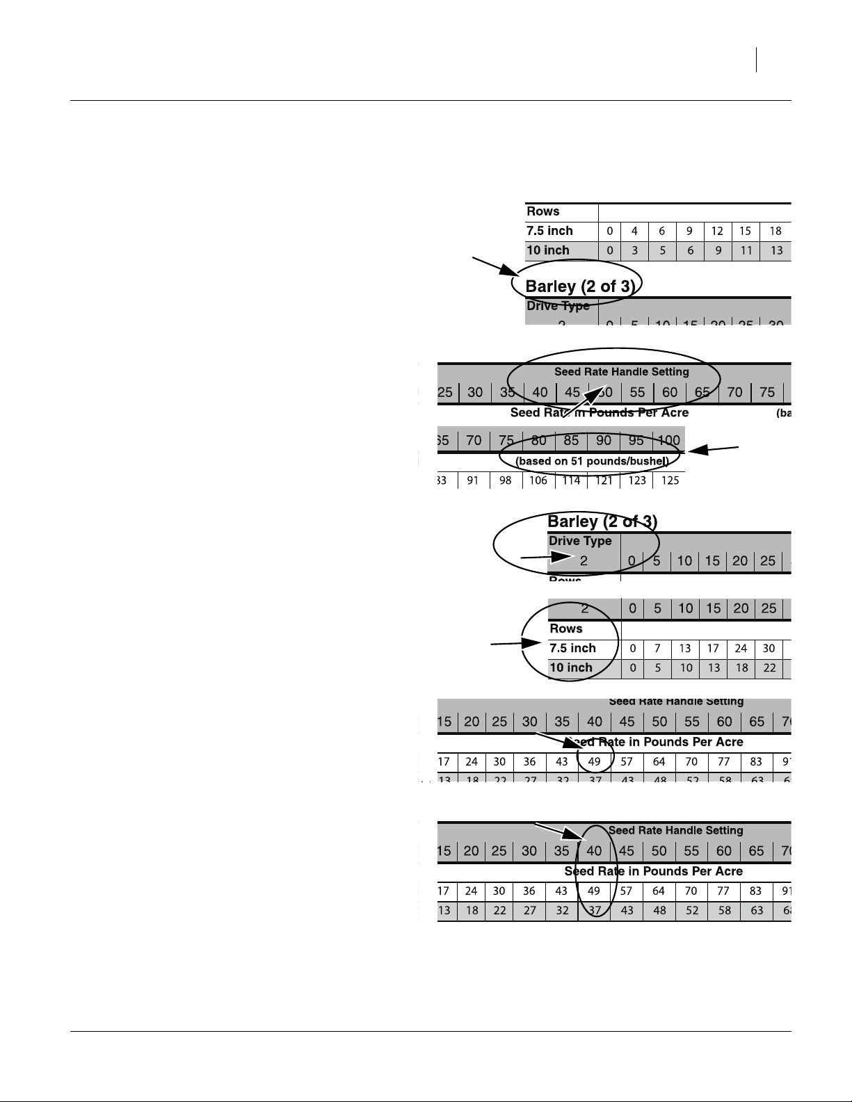
Reading a Seed Rate Chart
Charts in U.S. customary units begin on page 8.
Metric charts begin on page 25.
1. Find your seed. Charts are in alphabetical order by
seed name. Charts covering more than one seed
may be out of order.
For Rape, see Alfalfa.
For Sudan, see Flax.
This example presumes we desire to plant Barley at
50 pounds per acre with a 7.5in drill.
There are multiple charts for some seeds, and the
rates may overlap. Use the chart where your desired
rate is closest to 50 on the Seed Rate Handle scale.
In our example, that would be Barley chart 2 of 3.
If your seed is not listed, find one with similar size,
shape and density. Density of the test seed used to
develop the chart appears under the right end of the
handle scale values.
7
2. Note the Drive Type in the upper left corner of the
chart for your seed. This number (1-4) is used to
determine the seed jackshaft sprocket. See page 3.
In our example, this is Drive Type 2 (34T sprocket).
3. Find your row spacing in the far left column.
4. Locate your desired seed rate in the table row for
your row spacing.
In our example, 49 is the closest to 50.
5. Note the Seed Rate Handle setting required, at the
top of the column at that seed rate. This is the initial
value set on the Seed Rate Handle. See page 4.
In our example, we will start with a handle setting of
40, and calibrate. When a target rate falls halfway
between handle settings, you can adjust the handle
slightly to compensate, but calibration is apt to result
in further adjustment anyway.
01/29/2009 196-522B
Page 10
3S-4010HD and 3S-4010HDF
8
Great Plains Mfg., Inc.
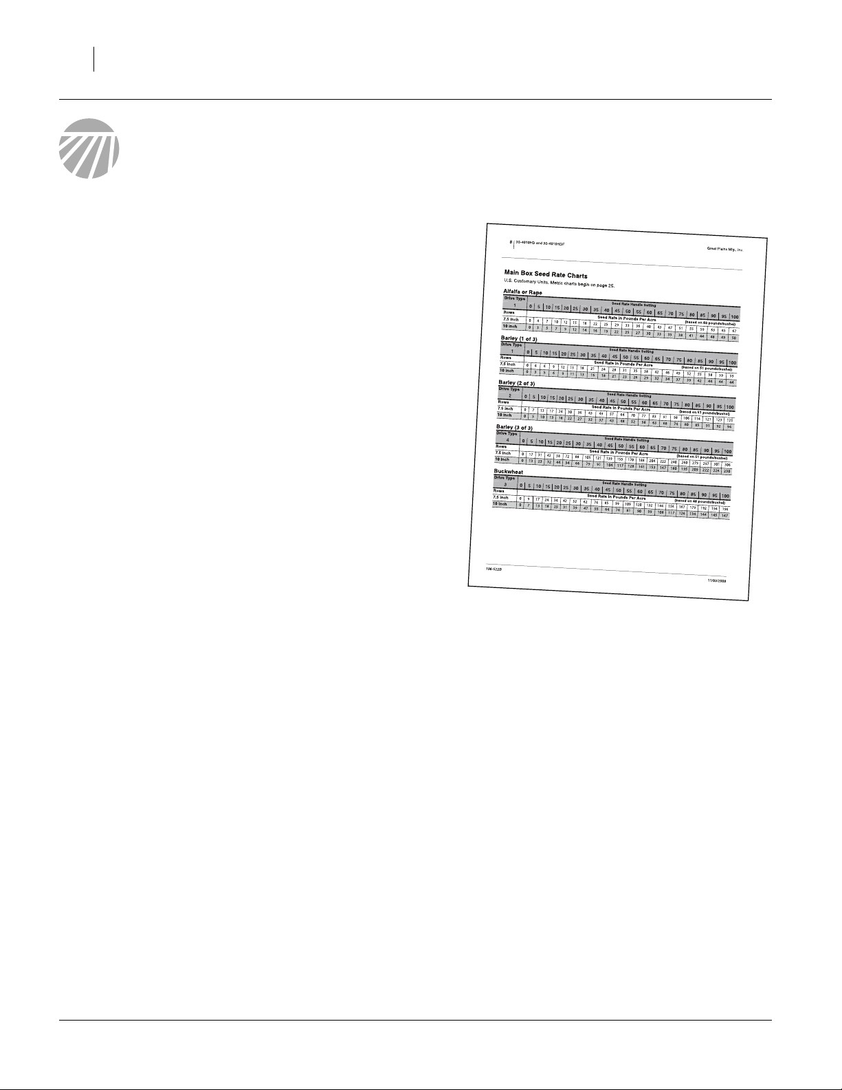
Main Box Seed Rate Charts
U.S. Customary Units. Metric charts begin on page 25.
Alfalfa or Rape
Drive Type
1 0 5 10 15 20 25 30 35 40 45 50 55 60 65 70 75 80 85 90 95 100
Rows Seed Rate in Pounds Per Acre (based on 60 pounds/bushel)
7.5 inch 04 7101215182225293336404347515559636567
10 inch 0 3 5 7 9 12 14 16 19 22 25 27 30 33 35 38 41 44 48 49 50
Barley (1 of 3)
Drive Type
1 0 5 10 15 20 25 30 35 40 45 50 55 60 65 70 75 80 85 90 95 100
Rows Seed Rate in Pounds Per Acre (based on 51 pounds/bushel)
7.5 inch 0 4 6 9 12 15 18 21 24 28 31 35 38 42 46 49 52 55 58 59 59
10 inch 0 3 5 6 9 11 13 16 18 21 23 26 29 32 34 37 39 42 44 44 44
Seed Rate Handle Setting
Seed Rate Handle Setting
Barley (2 of 3)
Drive Type
2 0 5 10 15 20 25 30 35 40 45 50 55 60 65 70 75 80 85 90 95 100
Rows Seed Rate in Pounds Per Acre (based on 51 pounds/bushel)
7.5 inch 071317243036434957647077839198106114121123125
10 inch 0 5 10 13 18 22 27 32 37 43 48 52 58 63 68 74 80 85 91 92 94
Seed Rate Handle Setting
Barley (3 of 3)
Drive Type
4 0 5 10 15 20 25 30 35 40 45 50 55 60 65 70 75 80 85 90 95 100
Rows Seed Rate in Pounds Per Acre (based on 51 pounds/bushel)
7.5 inch 0 17 31 42 58 72 88 105 121 139 155 170 188 204 222 240 260 279 297 301 306
10 inch 0 13 23 32 44 54 66 79 91 104 117 128 141 153 167 180 195 209 222 226 230
Seed Rate Handle Setting
Buckwheat
Drive Type
3 0 5 10 15 20 25 30 35 40 45 50 55 60 65 70 75 80 85 90 95 100
Rows Seed Rate in Pounds Per Acre (based on 48 pounds/bushel)
7.5 inch 0 9 17 24 34 42 52 62 74 85 99 109 120 132 144 156 167 179 192 194 196
10 inch 0 7 13 18 25 31 39 47 55 64 74 81 90 99 108 117 126 134 144 145 147
Seed Rate Handle Setting
196-522B 01/29/2009
Page 11
Great Plains Mfg., Inc.
9
Seed Rate Charts, Main Box, lbs/ac, continued...
Buffalograss (1 of 4)
Drive Type
1 0 5 10 15 20 25 30 35 40 45 50 55 60 65 70 75 80 85 90 95 100
Rows Seed Rate in Pounds Per Acre (based on 23 pounds/bushel)
7.5 inch 012345 7 8 10111314151718192020202020
10 inch 0 1 2 2 3 4 5 6 7 8 9 11 12 12 13 14 15 15 15 15 15
Buffalograss (2 of 4)
Drive Type
2 0 5 10 15 20 25 30 35 40 45 50 55 60 65 70 75 80 85 90 95 100
Rows Seed Rate in Pounds Per Acre (based on 23 pounds/bushel)
7.5 inch 0 2 4 6 8 11 14 17 20 23 26 29 32 34 36 38 40 41 42 42 41
10 inch 0 2 3 5 6 8 10 13 15 17 19 22 24 26 27 29 30 31 31 31 31
Seed Rate Handle Setting
Seed Rate Handle Setting
Buffalograss (3 of 4)
Drive Type
3 0 5 10 15 20 25 30 35 40 45 50 55 60 65 70 75 80 85 90 95 100
Rows Seed Rate in Pounds Per Acre (based on 23 pounds/bushel)
7.5 inch 0 5 7 9 12 16 20 24 29 34 38 43 47 51 55 58 61 63 64 65 64
10 inch 0 3 5 7 9 12 15 18 22 25 29 32 36 38 41 44 46 47 48 48 48
Seed Rate Handle Setting
Buffalograss (4 of 4)
Drive Type
4 0 5 10 15 20 25 30 35 40 45 50 55 60 65 70 75 80 85 90 95 100
Rows Seed Rate in Pounds Per Acre (based on 23 pounds/bushel)
7.5 inch 0 7 11 15 20 26 33 40 47 55 62 70 77 83 90 95 99 102 104 105 104
10 inch 0 6 8 11 15 20 25 30 35 41 47 52 58 63 67 71 74 77 78 79 78
Seed Rate Handle Setting
Flax or Sudan
Drive Type
1 0 5 10 15 20 25 30 35 40 45 50 55 60 65 70 75 80 85 90 95 100
Rows Seed Rate in Pounds Per Acre (based on 55 pounds/bushel)
7.5 inch 0 3 7 9 13 16 19 23 26 30 34 37 40 44 47 52 56 61 66 67 68
10 inch 0 2 5 7 10 12 15 17 20 22 25 27 30 33 35 39 42 45 49 50 51
Seed Rate Handle Setting
Millet
Drive Type
1 0 5 10 15 20 25 30 35 40 45 50 55 60 65 70 75 80 85 90 95 100
Rows Seed Rate in Pounds Per Acre (based on 60 pounds/bushel)
7.5 inch 0 4 7 9 13 16 19 22 25 29 32 35 39 42 46 49 53 57 61 62 63
10 inch 0 3 5 7 9 12 14 16 19 21 24 26 29 32 34 37 40 43 46 46 47
01/29/2009 196-522B
Seed Rate Handle Setting
Page 12

3S-4010HD and 3S-4010HDF
10
Great Plains Mfg., Inc.
Seed Rate Charts, Main Box, lbs/ac, continued...
Milo
Drive Type
1 0 5 10 15 20 25 30 35 40 45 50 55 60 65 70 75 80 85 90 95 100
Rows Seed Rate in Pounds Per Acre (based on 64 pounds/bushel)
7.5 inch 04 7101418222731364145505560656973788082
10 inch 0 3 5 8 11 14 17 20 23 27 31 34 38 41 45 49 52 55 59 60 61
Oats
Drive Type
3 0 5 10 15 20 25 30 35 40 45 50 55 60 65 70 75 80 85 90 95 100
Rows Seed Rate in Pounds Per Acre (based on 37 pounds/bushel)
7.5 inch 0 4 10 14 19 25 31 37 44 51 58 64 70 77 84 90 97 104 111 112 112
10 inch 0 3 7 10 14 19 23 28 33 38 43 48 53 58 63 68 73 78 83 84 84
Seed Rate Handle Setting
Seed Rate Handle Setting
Peas
Drive Type
3 0 5 10 15 20 25 30 35 40 45 50 55 60 65 70 75 80 85 90 95 100
Rows Seed Rate in Pounds Per Acre (based on 61 pounds/bushel)
7.5 inch 0 0 15 27 42 55 67 82 95 110 123 136 149 161 175 188 201 213 225 226 227
10 inch 0 0 11 20 31 41 50 61 71 82 93 102 112 121 131 141 151 160 169 170 171
Seed Rate Handle Setting
Pinto Beans
Drive Type
1 0 5 10 15 20 25 30 35 40 45 50 55 60 65 70 75 80 85 90 95 100
Rows Seed Rate in Pounds Per Acre (based on 51 pounds/bushel)
7.5 inch 00 7101419242833384247515560656873777777
10 inch 0 0 5 8 10 14 18 21 25 28 32 35 38 41 45 49 51 54 58 58 58
Seed Rate Handle Setting
Rice, Short Grain (1 of 2)
Drive Type
3 0 5 10 15 20 25 30 35 40 45 50 55 60 65 70 75 80 85 90 95 100
Rows Seed Rate in Pounds Per Acre (based on 43 pounds/bushel)
7.5 inch 0 9 14 23 31 37 44 51 59 67 77 85 94 102 111 118 125 132 139 139 139
10 inch 0 7 11 17 23 27 33 38 44 50 57 64 70 77 83 89 94 99 105 105 105
Seed Rate Handle Setting
Rice, Short Grain (2 of 2)
Drive Type
4 0 5 10 15 20 25 30 35 40 45 50 55 60 65 70 75 80 85 90 95 100
Rows Seed Rate in Pounds Per Acre (based on 43 pounds/bushel)
7.5 inch 0 14 24 37 50 60 72 83 96 109 125 139 153 167 181 193 204 215 227 227 227
10 inch 0 11 18 28 38 45 54 62 72 82 94 105 115 125 136 145 153 162 170 170 170
196-522B 01/29/2009
Seed Rate Handle Setting
Page 13

Great Plains Mfg., Inc.
11
Seed Rate Charts, Main Box, lbs/ac, continued...
Rice, Long Grain (1 of 4)
Drive Type
1 0 5 10 15 20 25 30 35 40 45 50 55 60 65 70 75 80 85 90 95 100
Rows Seed Rate in Pounds Per Acre (based on 47 pounds/bushel)
7.5 inch 0 1.1 3.6 5.9 8.3 10.9 13.5 15.9 18.4 20.9 25.3 25.7 28.1 30.5 32.9 35.4 37.5 39.5 41.2 42.3 43.1
10 inch 0 0.8 2.7 4.4 6.2 8.2 10.1 11.9 13.8 15.7 19.0 19.3 21.1 22.9 24.7 26.6 28.1 29.7 30.9 31.7 32.3
Rice, Long Grain (2 of 4)
Drive Type
2 0 5 10 15 20 25 30 35 40 45 50 55 60 65 70 75 80 85 90 95 100
Rows Seed Rate in Pounds Per Acre (based on 47 pounds/bushel)
7.5 inch 02 7121723283338435253586368737781858789
10 inch 0 2 6 9 13 17 21 25 28 32 39 40 43 47 51 55 58 61 64 65 67
Seed Rate Handle Setting
Seed Rate Handle Setting
Rice, Long Grain (3 of 4)
Drive Type
3 0 5 10 15 20 25 30 35 40 45 50 55 60 65 70 75 80 85 90 95 100
Rows Seed Rate in Pounds Per Acre (based on 47 pounds/bushel)
7.5 inch 0 0 11 17 25 34 42 49 57 65 72 79 85 92 100 108 116 123 129 134 138
10 inch 0 0 8 13 19 25 32 37 42 49 54 59 64 69 75 81 87 92 97 100 104
Seed Rate Handle Setting
Rice, Long Grain (4 of 4)
Drive Type
4 0 5 10 15 20 25 30 35 40 45 50 55 60 65 70 75 80 85 90 95 100
Rows Seed Rate in Pounds Per Acre (based on 47 pounds/bushel)
7.5 inch 0 0 17 28 41 55 69 80 92 105 117 128 139 151 163 176 188 200 210 218 226
10 inch 0 0 13 21 31 41 52 60 69 79 88 96 104 113 123 132 141 150 158 164 169
Seed Rate Handle Setting
Rye
Drive Type
1 0 5 10 15 20 25 30 35 40 45 50 55 60 65 70 75 80 85 90 95 100
Rows Seed Rate in Pounds Per Acre (based on 57 pounds/bushel)
7.5 inch 02 6101519222833384246505559646975818182
10 inch 0 2 5 8 11 14 17 21 24 28 32 35 38 41 44 48 52 56 61 61 61
Seed Rate Handle Setting
01/29/2009 196-522B
Page 14

3S-4010HD and 3S-4010HDF
12
Great Plains Mfg., Inc.
Seed Rate Charts, Main Box, lbs/ac, continued...
Soybeans (1 of 4)
Drive Type
1 0 5 10 15 20 25 30 35 40 45 50 55 60 65 70 75 80 85 90 95 100
Rows Seed Rate in Pounds Per Acre (based on 58 pounds/bushel)
7.5 inch 02 6111519232731364044495357626570747475
10 inch 0 2 5 8 12 14 17 20 24 27 30 33 37 40 43 46 49 52 56 56 56
Soybeans (2 of 4)
Drive Type
2 0 5 10 15 20 25 30 35 40 45 50 55 60 65 70 75 80 85 90 95 100
Rows Seed Rate in Pounds Per Acre (based on 58 pounds/bushel)
7.5 inch 0 5 13 22 32 38 47 55 64 73 81 91 100 109 118 127 134 143 152 153 153
10 inch 0 4 10 16 24 29 35 42 48 55 61 68 75 82 88 95 101 107 115 115 115
Seed Rate Handle Setting
Seed Rate Handle Setting
Soybeans (3 of 4)
Drive Type
3 0 5 10 15 20 25 30 35 40 45 50 55 60 65 70 75 80 85 90 95 100
Rows Seed Rate in Pounds Per Acre (based on 58 pounds/bushel)
7.5 inch 0 9 18 32 48 57 71 81 93 105 119 131 145 157 171 182 199 212 227 227 227
10 inch 0 7 14 24 36 42 53 61 70 79 89 98 108 118 128 137 149 159 170 170 170
Seed Rate Handle Setting
Soybeans (4 of 4)
Drive Type
4 0 5 10 15 20 25 30 35 40 45 50 55 60 65 70 75 80 85 90 95 100
Rows Seed Rate in Pounds Per Acre (based on 58 pounds/bushel)
7.5 inch 0 15 29 53 78 92 116 132 152 171 193 214 236 256 279 297 324 346 370 371 371
10 inch 0 11 22 40 58 69 87 99 114 128 145 160 177 192 209 223 243 260 278 278 278
Seed Rate Handle Setting
Sunflower
Drive Type
1 0 5 10 15 20 25 30 35 40 45 50 55 60 65 70 75 80 85 90 95 100
Rows Seed Rate in Pounds Per Acre (based on 28 pounds/bushel)
7.5 inch 002357 9 1012141618202224262729313233
10 inch 0 0 1 3 4 5 6 8 9 11 12 14 15 16 18 19 20 22 23 24 24
Seed Rate Handle Setting
196-522B 01/29/2009
Page 15

Great Plains Mfg., Inc.
13
Seed Rate Charts, Main Box, lbs/ac, continued...
Wheat (1 of 2)
Drive Type
2 0 5 10 15 20 25 30 35 40 45 50 55 60 65 70 75 80 85 90 95 100
Rows Seed Rate in Pounds Per Acre (based on 64 pounds/bushel)
7.5 inch 0 10 18 24 32 40 46 56 64 73 84 92 102 112 122 131 142 152 162 164 165
10 inch 0 8 13 18 24 30 34 42 48 55 63 69 76 84 91 99 106 114 122 123 124
Wheat (2 of 2)
Drive Type
3 0 5 10 15 20 25 30 35 40 45 50 55 60 65 70 75 80 85 90 95 100
Rows Seed Rate in Pounds Per Acre (based on 64 pounds/bushel)
7.5 inch 0 13 25 36 48 59 70 83 96 109 123 134 149 162 176 192 205 219 232 237 239
10 inch 0 10 18 27 36 45 53 62 72 82 92 101 111 121 132 144 154 164 174 178 179
Seed Rate Handle Setting
Seed Rate Handle Setting
Wheatgrass
Drive Type
1 0 5 10 15 20 25 30 35 40 45 50 55 60 65 70 75 80 85 90 95 100
Rows Seed Rate in Pounds Per Acre (based on 23 pounds/bushel)
7.5 inch 012234 5678910111112131415151717
10 inch 0 1 1 2 3 3 4 4 5 6 7 7 8 9 9 10 11 12 11 13 13
Seed Rate Handle Setting
01/29/2009 196-522B
Page 16

3S-4010HD and 3S-4010HDF
14
Setting Fertilizer Rate
The 3S-4010HDF fertilizer meters are driven from the
clutch shaft through a series of sprockets.This system is
independent of the seed meter drive, and is unaffected
by Drive Type. Fertilizer rate is adjusted by changing 1 to
4 sprockets on each drill section (3 or 6 pairs total).
Fertilizer application rates vary with fertilizer type, density and particle size. Relative humidity and field conditions can also affect application rates. The chart on
page 31 is based on fertilizer with average particle size
and a density of 65 pounds per cubic foot. Initially set
rate according to charts, then calibrate the drill to your
material as described on this page.
Perform initial setup and calibration for the right drill box.
Once determined, set the center and left boxes to match.
Accurately obtaining the desired application rate requires
four steps:
1. Adjusting target rate for large differences between
material and chart density.
2. Setting Range sprockets (from chart)
3. Setting initial Transmission (Driver / Driven) sprockets (from chart)
4. Calibration: checking actual application rate
Great Plains Mfg., Inc.
Adjusting for Density
The fertilizer meter rate chart is based on fertilizer with a
density of 65 pounds per cubic foot (1.04 kg/liter). If your
fertilizer density is within a few percent of that, skip step
a through step e and use calibration to determine final
Driver/Driven setup.
For larger variances, particularly with very low densities,
pre-compensating can simplify calibration, bychoosing a
different target chart value for the application rate.
a. Find your actual material density. Normally, this
reported on the container in which it was supplied. If
not, weigh a known volume and calculate it.
b. Find your material Density in the table at right, and
the Conversion Factor below it.
c. Adjust your target application rate prior to consulting
the Fertilizer Rate Chart.
AdjustedRate TargetRate ConversionFactor×=
d. Find the Adjusted rate in the Fertilizer Rate Chart.
e. Calibrate using the Adjusted rate sprocket setup.
Density: lbs/cu-ft
(kg/liter)
Conversion Factor 1.45 1.30 1.20 1.10
Density: lbs/cu-ft
(kg/liter)
Conversion Factor 1.00 0.93 0.87 0.81
Example: 64 row 7.5in drill
Your fertilizer has a density of 60 pounds/cubic-foot,
and you want to apply 140 pounds/acre. First, adjust
the density:
155 140 1.10×=
Example:
The adjusted 155 rate corresponds to either:
LOW Range 24T/12T Transmission, or
HIGH Range, and 12T/21T Transmission.
45.0
(0.72)
65.0
(1.04)
50.0
(0.80)
70.0
(1.12)
55.0
(0.88)
75.0
(1.20)
60.0
(0.96)
80.0
(1.28)
196-522B 01/29/2009
Page 17

Great Plains Mfg., Inc.
Setting Fertilizer Drive Range
Refer to the Fertilizer Rate Chart on page 31 to find the
correct Range sprocket size for your drill’s row spacing
and the target (or adjusted) application rate.
Ranges overlap. Choose a Range so that the Transmission (Driver/Driven)pairing is further from the end of that
Range chart, reducing the chances that a Transmission
adjustment might also require a Range change.
Change fertilizer range requires changing one or two
sprockets per drill section, per the table at right. An idler
1
is loosed and re-engaged for any sprocket change.
Refer to Figure7
Range: Front Sprocket
15T
The two Front range sprockets ( , ) are permanently installed, and are exchanged by sliding left and
right on the shaft. Remove the spring-clasp polymer
spacer to permit sliding, and re-insert it as instructed
2
below to keep the Front and Rear sprockets aligned.
41T
15
In our example, two settings are near the adjusted rate:
LOW Range 24T/12T Transmission, or
HIGH Range, and 12T/21T Transmission.
Use the HIGH Range setting, as it is further from the
end of the chart, allowing easier adjustment.
Fertilizer Range
Sprockets Low High
Front 15T 41T 41T
Rear 60T 47T 16T
Ultra
High
Range: Rear Sprocket
There are three possible Rear range sprockets ( ,
47T 60T
, ). Remove a lynch pin (not shown) to change
3
16T
this sprocket.
The two rear range sprockets not presently in use are
stored on the Driven Transmission shaft , directly
4
below the Rear range shaft.
There are also main box Drive Type sprockets stored
here, but the tooth counts are unique to each drive.Tooth
counts are stamped into the face of each sprocket.
Changing Range Sprockets
1. Loosen the Range idler.
2. If the Front sprocket needs changing:
remove the polymer spacer ;
slide both sprockets to where spacer was; and,
re-clasp spacer on the other side of sprocket pair.
3. If the Rear sprocket needs changing:
remove the pin from the rear and storage shafts;
remove the current Rear sprocket ;
remove the next sprocket from storage;
place the next sprocket on the Rear shaft and re-pin;
return other sprockets to the lower shaft and re-pin.
4. Re-engage the Range idler for
the top chain span.
5. If this is the final Range setting, after calibration,
repeat step 1 through step 4 for the center and left
drill sections.
2
3
1
⁄
in (6.4mm) slack in
4
4
3
2
41T
4
15T
1
Figure 7
Range Sprockets: Center Section
15T Front Engaged (Low Range)
28179
01/29/2009 196-522B
Page 18

3S-4010HD and 3S-4010HDF
16
Setting Fertilizer Transmission
Refer to Figure8
The fertilizer Transmission is a Driver/Driven pair of
sprockets located above and behind the Drive Type
sprocket.
Refer to the Fertilizer Rate Charts (pages 19, 20, 31 and
32) to find the correct Transmission (Driver/Driven)
sprocket sizes for your drill’s row spacing and target (or
adjusted) application rate.
DRIVEN
Great Plains Mfg., Inc.
4
DRIVER
2
1
Examine the currently installed sprockets ( , ) to con-
1 2
firm that one or both needs to be changed (or moved
between shafts).
To change the transmission setting:
1. Loosen idlers and rotate idlers out of engagement
3
with chain.
2. Remove pin from vertical storage tower , and
4
retrievenewsprocket(s)required.Return other to the
storage tree, but leave pin off.
3. Remove lynch pinsfrom Driver and/or Driven
sprocket shaft to be changed, and remove
sprocket(s).
4. Place correct Driver and Driven sprockets on their
respective shafts.
5. Store removed sprockets on storage tree.
6. Re-install all pins.
7. Reinstall chain and engage idlers, allowing
1
⁄
in
4
(6.4mm) slack in the top chain span.
8. If this is the final setting, after calibration, repeat step
1 through step 7 for the center and left drill sections.
3
Figure 8
Fertilizer Transmission
28178
196-522B 01/29/2009
Page 19

Great Plains Mfg., Inc.
Fertilizer Rate Calibration
Differences will exist between the tested fertilizer and
field conditions used to generate the Rate Chart, and
your fertilizer and conditions. To accurately achieve your
target application, Great Plains recommends calibrating.
Perform the calibration with the drill lowered to field position. Shut off power to the clutches.
If you have previously calibrated your acremeter (see
Operator’s manual), you can use it to tally acres.
Refer to Figure9
1. Lower drill. Set MASTER switch on clutch control
box to OFF position.
2. Remove the calibration crank from its storage location on the right section drive. Remove pin from
crank and return to storage stob.
3. On the right drill section, if seed rate is not also being
calibrated at the same time, and seed is present,
remove the seed box drive chain.
Refer to Figure10
4. Install crank on clutch shaft of right section.
Crank rotation is clockwise, facing to drill left.
5. Use crank to turn clutch shaft and check that the
drives and seed cups are engaged, working properly
and free from foreign material.
Figure 9
Stored Calibration Crank
17
29240
Figure 10
28180
Installed Calibration Crank
6. From the charts, configure the Range and Transmission sprock
ets based on the target or density-
adjusted application rate.
For example:
you desire to apply 60lb/cu-ft material at a rate of:
141 lb/ac
on a 64 row 7.5in drill.
Per the density adjustment on page 14,
the adjusted rate is:
155 pounds/acre
Per the chart, the drive system setup is:
HIGH Range, and
12T/21T Transmission (Driver/Driven)
7. Record the weight of one to three empty containers
collectivelylarge enough to hold fertilizermetered for
6% of one acre or hectare.
01/29/2009 196-522B
For example:
three empty 8 oz. containers weigh: 1.5 lb.
Page 20

3S-4010HD and 3S-4010HDF
18
8. Place several pounds or kilograms of fertilizer over
three fertilizer openings at the outside end of the
right drill box. Pull lower end fertilizer hoses off of
these drops at the opener end.
9. Turn crank several times to fill flute cups. Turn until
fertilizer drops to ground from each hose.
10. Place empty container(s) under the three hoses to
gather metered fertilizer.
11. Turn crank for acre (45.1 rotations) or one hectare
(111.4 rotations). While turning, check that cups
have ample fertilizer coming into them.
12. Weigh metered fertilizer. Subtract initial weight of
container(s).
NetWeight GrossWeight ContainerWeights–=
Great Plains Mfg., Inc.
!
CAUTION
Follow material supplier recommendations for safety precautions in handling fertilizer.
For example:
the three containers weighed a total of 8.9 lb. after test:
7.4 lb. net
7.4 8.9 1.5–=
13. Divide the net fertilizer weight by three. Multiply by
number of openers on your drill to determine the
total of kg or pounds-per-acre applied.
NetWeight
MeasuredRate
14. Subtract to calculate the difference between the
measured rate and the original target (not adjusted)
rate.
Variance TargetRate MeasuredRate–=
15. If a Density Adjustment was made (see page 14),
apply it to the variance.
AdjustedVariance Variance CorrectionFactor×=
16. Consult the chart for the chart rate used for your first
calibration run with this material. If the just-measured
result was low, add the [adjusted] variance to the
previously used chart rate. If the measured result
was high, subtract the [adjusted] variance from the
previous chart rate.
17. Reset the fertilizer Range and Final Drive based on
the settings at the new chart rate.
18. You may want to repeat calibration procedure if your
results varied greatly from the desired target rate.
19. With calibration complete, Reinstall seed chain (if
removed) or reset Seed Rate Handle, reconnect
hoses, and lower gauge wheel to ground.
20. Set the center and left drill sections to match the
now-calibrated right section.
When drilling, check metering rate by noting acres
drilled, amount of fertilizer added to drill and level of
material in drill box. If you are applying more or less fertilizer than desired, adjust metering rate slightly to compensate for field conditions.
------------------------3
RowCount×=
For example:
a 64-row (7.5cm) drill:
158 lb/ac
7.4
157.9
For example: the target rate was 141 lb/ac:
variance=17
17 158 141–=
For example: the density adjustment factor was 1.10:
new variance=19
19 17 1.1×=
For example:
Our measured rate was high, so we
subtract the adjusted variance (19)
from the previous adjusted chart rate (155)
to obtain a new adjusted chart rate (137).
This is close to:
LOW chart rate 137, and
HIGH chart rate 135.
Use either new drive setup:
Rate:
Range:
Driver:
Driven:
-----3
137
LOW
23T
13T
64×=
Rate:
Range:
Driver:
Driven:
135
HIGH
12T
24T
196-522B 01/29/2009
Page 21

Great Plains Mfg., Inc.
Fertilizer Rate Charts, U.S. Customary Units
Fertilizer Rate, 7.5in Row Spacing
Based on 65 pounds per cubic foot
(see page 31 for 19.2cm metric chart))
7.5in Fertilizer Rate 7.5in Fertilizer Rate
Row Spacing Pounds per Acre Row Spacing Pounds per Acre
TRANSMISSION Fertilizer Rates by RANGE TRANSMISSION Fertilizer Rates by RANGE
Sprockets
DRIVER DRIVEN HIGH DRIVER DRIVEN HIGH
12T 24T 39 135 397 18T 17T 82 287 758
12T 23T 40 141 414 13T 12T 84 293 766
13T 24T 42 147 429 23T 21T 85 297 774
12T 21T 44 155 452 20T 18T 86 301 775
12T 20T 47 162 473 18T 16T 87 305 785
13T 21T 48 168 485 23T 20T 89 311 792
13T 20T 50 176 510 21T 18T 91 316 803
12T 18T 52 180 520 20T 17T 91 319 810
16T 23T 54 188 542 24T 20T 93 325 815
12T 17T 55 191 547 16T 13T 95 333 836
17T 23T 57 200 568 21T 17T 96 335 828
18T 24T 58 203 576 20T 16T 97 339 838
16T 21T 59 206 586 23T 18T 99 346 845
18T 23T 61 212 596 21T 16T 102 355 868
16T 20T 62 217 610 24T 18T 103 361 870
17T 21T 63 219 617 23T 17T 105 366 883
20T 24T 65 226 629 18T 13T 107 375 891
17T 20T 66 230 642 24T 17T 110 382 897
18T 21T 67 232 647 17T 12T 110 383 900
20T 23T 67 235 651 23T 16T 112 389 901
18T 20T 70 244 673 18T 12T 116 405 928
21T 23T 71 247 676 20T 13T 119 416 939
12T 13T 72 250 683 21T 13T 125 435 963
17T 18T 73 256 692 20T 12T 129 449 983
20T 21T 74 258 697 21T 12T 136 469 1012
23T 24T 74 259 702 23T 13T 137 475 1015
21T 21T 78 271 724 24T 13T 143 493 1051
24T 23T 81 283 747 23T 12T 149 512 1080
21T 20T 81 284 751 24T 12T 155 531 1121
LOW HIGH
ULTRA Sprockets
ULTRA
LOW HIGH
19
01/29/2009 196-522B
Page 22

3S-4010HD and 3S-4010HDF
20
Great Plains Mfg., Inc.
Fertilizer Rate, lbs/ac, 10in Row Spacing
Based on 65 pounds per cubic foot
(see page 32 for 25.4cm metric chart))
10in Fertilizer Rate 10in Fertilizer Rate
Row Spacing Pounds per Acre Row Spacing Pounds per Acre
TRANSMISSION Fertilizer Rates by RANGE TRANSMISSION Fertilizer Rates by RANGE
Sprockets
DRIVER DRIVEN HIGH DRIVER DRIVEN HIGH
LOW HIGH
12T 24T 29 102 300 18T 17T 62 217 573
12T 23T 31 107 313 13T 12T 64 222 579
13T 24T 32 111 324 23T 21T 64 224 585
12T 21T 34 117 342 20T 18T 65 227 586
12T 20T 35 123 357 18T 16T 66 230 594
13T 21T 36 127 367 23T 20T 67 235 599
13T 20T 38 133 385 21T 18T 68 239 608
12T 18T 39 136 393 20T 17T 69 241 613
16T 23T 41 142 410 24T 20T 70 246 617
12T 17T 41 145 413 16T 13T 72 252 632
17T 23T 43 151 430 21T 17T 72 253 626
18T 24T 44 154 436 20T 16T 73 256 634
16T 21T 45 156 443 23T 18T 75 262 639
18T 23T 46 160 451 21T 16T 77 269 657
16T 20T 47 164 461 24T 18T 78 273 658
17T 21T 47 166 466 23T 17T 79 277 667
20T 24T 49 171 476 18T 13T 81 283 674
17T 20T 50 174 485 24T 17T 83 289 678
18T 21T 50 175 490 17T 12T 83 290 680
20T 23T 51 178 492 23T 16T 84 294 681
18T 20T 53 184 509 18T 12T 88 306 702
21T 23T 54 187 511 20T 13T 90 314 710
12T 13T 54 189 517 21T 13T 95 329 728
17T 18T 55 193 523 20T 12T 98 339 743
20T 21T 56 195 527 21T 12T 103 355 765
23T 24T 56 196 531 23T 13T 104 359 767
21T 21T 59 205 547 24T 13T 108 373 795
24T 23T 61 214 565 23T 12T 112 387 817
21T 20T 62 215 568 24T 12T 117 401 848
ULTRA Sprockets
ULTRA
LOW HIGH
196-522B 01/29/2009
Page 23

Great Plains Mfg., Inc.
Small Seeds Rate
21
Seeding rate from the optional Small Seeds Attachment
is controlled entirely by seed rate handles on each small
seeds box. No sprocket changes are required, and small
seeds rate is unaffected by settings for main seed box.
Refer to Figure11
To set Small Seeds rate, loosen the wing nut at each
handle, and adjust the lever position. Tighten nut.
2
1
Small Seeds Rate Calibration
Differences will exist between the tested seed and field
conditions used to generate the Small Seeds Rate
Charts, and your seed and conditions. To accurately
achieve your target population, Great Plains recommends calibrating.
As small seed rates are typically far lower than main box
seed rates, use a scale that is accurate for small weight
differences, or sample more than the usual three rows.
1. Lower drill. Set MASTER switch on clutch control
box to OFF position.
2. Set the small seed rate handle based on the seed
and rate desired.
Refer to Figure12
3. Remove the calibration crank from its storage location on the right section drive. Remove pin from
crank and return to storage stob.
4. On the right drill section, if fertilizer rate is not also
being calibrated at the same time, and fertilizer is
present, remove a fertilizer box drive chain on the
right drill section.
2
1
Figure 11
Small Seeds Rate Handle
For example: using a row spacing of:
7.5in
and a row count of:
64
you desire to plant alfalfa at:
8 lbs/ac;
this corresponds to an initial Seed Rate Handle of:
40
18511
Figure 12
Stored Calibration Crank
Refer to Figure13
5. Install crank on clutch shaft of right section.
Crank rotation is clockwise, facing to drill left.
6. Use crank to turn clutch shaft and check that the
drives and seed cups are engaged, working properly
and free from foreign material. If not already done,
set the Small Seeds Rate Handle.
Figure 13
Installed Calibration Crank
01/29/2009 196-522B
29240
28180
Page 24

3S-4010HD and 3S-4010HDF
22
7. Check that your gauge-wheel tires are 18-22.5 (445/
65 D22.5) NHS 16-Ply and properly inflated. See
“Tire Inflation Chart” in Operator’s manual.
Great Plains Mfg., Inc.
8. Record the weight of one to three empty containers
collectively large enough to hold seed metered for
6% of one acre.
9. Place several pounds or kilograms of seed over
three seed cups on the outside end of the right drill
box. Pull lower end seed hoses off of these drops at
the opener end.
10. Turn crank several times to fill seed cups. Turn until
seed drops to ground from each hose.
11. Place empty container(s) under the three hoses to
gather metered seed.
12. Turn crank for one acre (45.1 rotations) or one hectare (111.4 rotations). While turning, check that cups
have ample seed coming into them.
13. Weigh metered seed. Subtract initial weight of container(s).
NetWeight GrossWeight ContainerWeights–=
14. Divide the net seed weight by the number of rows
sampled (3 in our example). Multiply by number of
openers on your drill to determine the total of
pounds-per-acre seeded.
NetWeight
MeasuredRate
------------------------3
RowCount×=
For example:
three 8 oz. containers weigh at total of:
1.5 lb
For example:
the three containers weighed a total 1.82 lb. after test:
0.32 lb. net
0.32 1.82 1.5–=
For example:
a 7.5in drill has 64 rows:
6.7 lbs/ac
0.32
---------
6.7
64×=
3
15. The Seed Rate Handle scale is a percentage of
meter opening, and is quite linear near scale center.
Calculate a new scale setting based on the test.
TargetRate
NewScale
--------------------------------MeasuredRate
OldScale×=
Note: You may want to repeat calibration procedure if
your results varied greatly from the Seed Rate
Chart, or if you must operate near the ends of the
Seed Rate handle scale (0-20 or 90-100).
16. Set the center and left drill sections to match the
now-calibrated right section.
17. With calibration complete, Reinstall fertilizer chain (if
removed), and reconnect seed hoses.
When drilling, check seeding rate by noting acres drilled,
amount of seed added to drill and seed level in drill box.
If you are seeding more or less than desired, adjust rate
slightly to compensate for field conditions.
For example:
new scale:
48
8
------
48
6.7
40×=
196-522B 01/29/2009
Page 25

Great Plains Mfg., Inc.
Small Seeds Rate Charts, U.S. Customary Units
See page 21 for instructions. Metric charts begin on page 33.
Alfalfa, Red Alsike, Crimson Clover
Small Seeds Cup Lever Setting
0 5 10 15 20 25 30 35 40 45 50 55 60 65 70 75 80 85 90 95 100
Rows Seeding Rate in Pounds per Acre
7.5 inch 0 0.0 1.8 2.8 3.9 4.8 6.0 7.0 7.9 9.0 10.0 11.1 12.1 13.2 14.0 15.3 16.2 17.2 18.3 19.3 20.3
10 inch 0 0.0 1.3 2.1 2.8 3.5 4.4 5.1 5.8 6.6 7.4 8.1 8.9 9.7 10.3 11.2 11.9 12.6 13.4 14.2 14.9
Kentucky Bluegrass, Fescue, Annual Rye Grass
Small Seeds Cup Lever Setting
0 5 10 15 20 25 30 35 40 45 50 55 60 65 70 75 80 85 90 95 100
Rows Seeding Rate in Pounds per Acre
7.5 inch 0 0.0 0.2 .9 1.5 2.2 2.7 3.3 3.7 4.2 4.6 5.1 5.5 5.9 6.3 6.7 7.0 7.4 7.7 8.1 8.4
10 inch 0 0.0 0.1 0.7 1.1 1.6 2.0 2.4 2.7 3.1 3.4 3.7 4.0 4.3 4.6 4.9 5.2 5.4 5.7 5.9 6.2
23
Bermuda, Red Top, Lespedeza Unhulled, Sercia, Sand, Weeping Love Grass
Small Seeds Cup Lever Setting
0 5 10 15 20 25 30 35 40 45 50 55 60 65 70 75 80 85 90 95 100
Rows Seeding Rate in Pounds per Acre
7.5 inch 0 0.0 0.5 0.9 1.4 2.1 2.6 3.3 4.0 4.7 5.3 5.8 6.3 6.7 7.2 7.6 8.2 8.8 9.3 9.8 10.4
10 inch 0 0.0 0.4 0.6 1.0 1.5 1.9 2.4 3.0 3.5 3.9 4.2 4.6 4.9 5.3 5.6 6.0 6.4 6.8 7.2 7.6
Red & Sweet Clover, Lespedeza Hulled
Small Seeds Cup Lever Setting
0 5 10 15 20 25 30 35 40 45 50 55 60 65 70 75 80 85 90 95 100
Rows Seeding Rate in Pounds per Acre
7.5 inch 0 0.0 1.2 2.7 4.2 5.7 7.2 9.1 10.6 12.3 13.7 15.3 16.7 18.1 19.7 21.2 22.7 24.2 25.8 27.2 28.6
10 inch 0 0.0 0.9 2.0 3.1 4.2 5.3 6.7 7.8 9.0 10.0 11.2 12.2 13.3 14.4 15.6 16.6 17.8 18.9 19.9 20.9
Orchard Grass
Small Seeds Cup Lever Setting
0 5 10 15 20 25 30 35 40 45 50 55 60 65 70 75 80 85 90 95 100
Rows Seeding Rate in Pounds per Acre
7.5 inch 0 0.0 0.0 0.2 0.5 0.7 1.1 1.2 1.6 1.9 2.3 2.6 2.8 3.2 3.5 3.9 4.0 4.4 4.6 4.9 5.1
10 inch 0 0.0 0.0 0.1 0.4 0.5 .8 0.9 1.2 1.4 1.7 1.9 2.1 2.3 2.6 2.8 3.0 3.2 3.3 3.6 3.7
Millet, Reed Canary
Small Seeds Cup Lever Setting
0 5 10 15 20 25 30 35 40 45 50 55 60 65 70 75 80 85 90 95 100
Rows Seeding Rate in Pounds per Acre
7.5 inch 0 0.3 1.2 2.0 2.8 3.6 4.4 5.2 6.0 6.8 7.6 8.4 9.3 10.1 10.9 11.7 12.5 13.3 14.1 14.9 15.1
10 inch 0 0.3 0.8 1.4 2.0 2.6 3.2 3.8 4.4 5.0 5.6 6.2 6.8 7.4 8.0 8.6 9.2 9.8 10.4 10.9 11.5
01/29/2009 196-522B
Page 26

3S-4010HD and 3S-4010HDF
24
Great Plains Mfg., Inc.
Small Seeds Rates, lbs/ac, continued...
Ladino Clover, Canary Grass, Timothy, Canola
Small Seeds Cup Lever Setting
0 5 10 15 20 25 30 35 40 45 50 55 60 65 70 75 80 85 90 95 100
Rows Seeding Rate in Pounds per Acre
7.5 inch 0 0.0 0.9 1.6 2.6 3.9 4.9 6.1 7.4 8.6 9.8 11.1 12.5 13.7 14.9 16.3 17.6 18.8 20.4 21.9 23.5
10 inch 0 0.0 0.6 1.5 1.9 2.5 3.6 4.5 5.4 6.3 7.2 8.1 9.1 10.0 10.9 12.0 12.9 13.8 14.9 16.1 17.2
Birdsfoot, Trefoil, Sudan
Small Seeds Cup Lever Setting
0 5 10 15 20 25 30 35 40 45 50 55 60 65 70 75 80 85 90 95 100
Rows Seeding Rate in Pounds per Acre
7.5 inch 0 0.0 1.4 2.6 4.2 5.4 7.0 8.6 10.2 11.9 13.5 15.4 17.0 18.8 20.5 22.5 24.0 25.8 27.6 29.1 30.9
10 inch 0 0.0 1.0 1.9 3.1 4.0 5.1 6.3 7.5 8.6 9.9 11.3 12.5 13.8 15.1 16.5 17.6 18.9 20.2 21.4 22.7
196-522B 01/29/2009
Page 27

Great Plains Mfg., Inc.
Appendix
Main Seed Box Rate Charts, Metric
See page 2 for instructions. Charts in U.S. customary units begin on page 8.
Alfalfa or Rape
Drive Type
1 0 5 10 15 20 25 30 35 40 45 50 55 60 65 70 75 80 85 90 95 100
Rows Seed Rate in Kilograms per Hectare (based on 0.77 kg per liter)
19.2cm (7.5in)
25.4cm (10in)
0 4.9 7.5 10.8 13.8 17.2 20.5 24.4 28.3 33.0 36.8 40.3 44.6 48.7 53.0 56.8 61.7 66.4 71.2 73.3 75.4
0 3.7 5.6 8.1 10.3 12.9 15.4 18.3 21.2 24.7 27.6 30.2 33.5 36.5 39.7 42.6 46.3 49.7 53.4 55.0 56.6
Barley (1 of 3)
Drive Type
1 0 5 10 15 20 25 30 35 40 45 50 55 60 65 70 75 80 85 90 95 100
Rows Seed Rate in Kilograms per Hectare (based on 0.66 kg per liter)
19.2cm (7.5in)
25.4cm (10in)
0 4.0 6.8 9.5 12.9 16.3 20.0 23.5 27.1 31.0 34.9 38.8 43.0 47.4 51.3 55.5 58.8 62.1 65.2 65.7 68.2
0 3.0 5.1 7.2 9.7 12.1 14.9 17.6 20.3 23.2 26.2 29.2 32.2 35.6 38.5 41.5 44.1 46.6 48.8 49.3 49.6
Seed Rate Handle Setting
Seed Rate Handle Setting
25
Barley (2 of 3)
Drive Type
2 0 5 10 15 20 25 30 35 40 45 50 55 60 65 70 75 80 85 90 95 100
Rows Seed Rate in Kilograms per Hectare (based on 0.66 kg per liter)
19.2cm (7.5in)
25.4cm (10in)
0 7.7 14.3 19.3 26.7 33.2 40.5 48.3 55.5 63.8 71.3 78.1 86.1 93.5 101.9 110.1 119.2 127.9 136.1 138.2 140.4
0 5.8 10.7 14.5 20.1 24.9 30.4 36.2 41.7 47.8 53.4 58.6 64.6 70.2 76.5 82.6 89.5 95.9 100.1 103.7 105.3
Seed Rate Handle Setting
Barley (3 of 3)
Drive Type
4 0 5 10 15 20 25 30 35 40 45 50 55 60 65 70 75 80 85 90 95 100
Rows Seed Rate in Kilograms per Hectare (based on 0.66 kg per liter)
19.2cm (7.5in)
25.4cm (10in)
0 19.0 34.8 47.4 65.5 81.2 99.1 118.0 135.7 155.9 174.4 191.1 210.5 228.7 249.5 269.4 291.7 312.8 332.9 338.2 343.4
0 14.3 26.2 35.5 49.1 60.9 74.3 88.5 101.8 117.0 130.8 143.3 157.9 171.5 187.0 202.1 218.8 234.6 249.7 253.6 257.7
Seed Rate Handle Setting
Buckwheat
Drive Type
3 0 5 10 15 20 25 30 35 40 45 50 55 60 65 70 75 80 85 90 95 100
Rows Seed Rate in Kilograms per Hectare (based on 0.62 kg per liter)
19.2cm (7.5in)
25.4cm (10in)
0 10.1 18.9 26.5 37.6 46.9 58.4 70.1 83.0 95.9 110.6 121.8 135.1 148.5 161.2 175.6 187.9 201.2 214.4 214.6 218.9
0 7.6 14.1 19.9 28.2 35.1 43.8 52.5 62.2 72.0 83.0 91.4 101.3 111.4 120.9 131.7 141.0 150.9 160.8 164.7 170.1
Seed Rate Handle Setting
01/29/2009 196-522B
Page 28

3S-4010HD and 3S-4010HDF
26
Great Plains Mfg., Inc.
Main Box Rates, Metric, continued...
Buffalograss (1 of 4)
Drive Type
1 0 5 10 15 20 25 30 35 40 45 50 55 60 65 70 75 80 85 90 95 100
Rows Seed Rate in Kilograms per Hectare (based on 0.30 kg per liter)
19.2cm (7.5in)
25.4cm (10in)
0 1.1 2.3 3.4 4.5 5.6 7.9 9.0 11.3 12.4 14.6 15.8 16.9 19.2 20.3 21.4 22.5 22.5 22.5 22.5 22.5
0 1.1 2.3 2.3 3.4 4.5 5.6 6.8 7.9 9.0 10.1 12.4 13.5 13.5 14.6 15.8 16.9 1ˇˇˇ 16.9 16.9 16.9
Seed Rate Handle Setting
Buffalograss (2 of 4)
Drive Type
2 0 5 10 15 20 25 30 35 40 45 50 55 60 65 70 75 80 85 90 95 100
Rows Seed Rate in Kilograms per Hectare (based on 0.30 kg per liter)
15.2cm (6in)
19.2cm (7.5in)
25.4cm (10in)
0 3.4 5.6 9.0 12.4 15.8 19.2 23.7 28.2 32.7 36.1 40.6 43.9 48.5 51.8 54.1 56.3 57.5 58.6 58.6 58.6
0 2.3 4.5 6.8 9.0 12.4 15.8 19.2 22.5 25.9 29.3 32.7 36.1 38.3 40.6 42.8 45.1 46.2 47.3 47.3 46.2
0 2.3 3.4 5.6 6.8 9.0 11.3 14.6 16.9 19.2 21.4 24.8 27.0 29.3 30.4 32.7 33.8 34.9 34.9 34.9 34.9
Seed Rate Handle Setting
Buffalograss (3 of 4)
Drive Type
3 0 5 10 15 20 25 30 35 40 45 50 55 60 65 70 75 80 85 90 95 100
Rows Seed Rate in Kilograms per Hectare (based on 0.30 kg per liter)
19.2cm (7.5in)
25.4cm (10in)
0 5.6 7.9 10.1 13.5 18.0 22.5 27.0 32.7 38.3 42.8 48.5 53.0 57.5 62.0 65.4 68.7 71.0 72.1 73.2 72.1
0 3.4 5.6 7.9 10.1 13.5 16.9 20.3 24.8 28.2 32.7 36.1 40.6 42.8 46.2 49.6 51.8 53.0 54.1 54.1 54.1
Seed Rate Handle Setting
Buffalograss (4 of 4)
Drive Type
4 0 5 10 15 20 25 30 35 40 45 50 55 60 65 70 75 80 85 90 95 100
Rows Seed Rate in Kilograms per Hectare (based on 0.30 kg per liter)
19.2cm (7.5in)
25.4cm (10in)
0 7.9 12.4 16.9 22.5 29.3 37.2 45.1 53.0 62.0 69.9 78.9 86.8 93.5 101.4 107.0 111.6 114.9 117.2 118.3 117.2
0 6.5 9.0 12.4 16.9 22.5 28.2 33.8 39.4 46.2 53.0 58.6 65.4 71.0 75.5 80.0 83.4 86.8 87.9 89.0 87.9
Seed Rate Handle Setting
Flax or Sudan
Drive Type
1 0 5 10 15 20 25 30 35 40 45 50 55 60 65 70 75 80 85 90 95 100
Rows Seed Rate in Kilograms per Hectare (based on 0.71 kg per liter)
19.2cm (7.5in)
25.4cm (10in)
0 3.4 7.4 10.6 14.5 18.1 21.7 25.4 29.4 33.2 37.6 41.1 44.8 48.8 53.1 58.0 62.6 68.0 73.5 74.8 76.2
0 2.5 5.5 7.9 10.9 13.6 16.3 19.1 22.1 24.9 28.2 30.8 33.6 36.6 39.7 43.6 47.0 51.0 55.2 56.0 57.1
Seed Rate Handle Setting
Millet
Drive Type
1 0 5 10 15 20 25 30 35 40 45 50 55 60 65 70 75 80 85 90 95 100
Rows Seed Rate in Kilograms per Hectare (based on 0.77 kg per liter)
19.2cm (7.5in)
25.4cm (10in)
196-522B 01/29/2009
0 4.2 7.4 10.6 14.0 17.5 21.0 24.5 28.3 32.0 35.7 39.5 43.6 47.0 51.2 55.5 59.3 63.5 68.0 69.2 70.2
0 3.1 5.5 7.9 10.6 13.1 15.7 18.3 21.2 24.0 26.8 29.6 32.7 35.4 38.4 41.5 44.5 47.7 51.1 51.9 52.7
Seed Rate Handle Setting
Page 29

Great Plains Mfg., Inc.
Main Box Rates, Metric, continued...
Milo
Drive Type
1 0 5 10 15 20 25 30 35 40 45 50 55 60 65 70 75 80 85 90 95 100
Rows Seed Rate in Kilograms per Hectare (based on 0.82 kg per liter)
19.2cm (7.5in)
25.4cm (10in)
0 4.2 7.9 11.7 15.9 20.2 24.9 30.1 35.0 40.3 46.3 51.0 56.5 61.9 67.1 72.5 77.8 82.3 87.7 90.0 91.6
0 3.1 6.0 8.8 11.9 15.2 18.7 22.6 26.3 30.2 34.7 38.2 42.3 46.4 50.3 54.5 58.4 61.7 65.8 67.6 68.7
Seed Rate Handle Setting
Oats
Drive Type
3 0 5 10 15 20 25 30 35 40 45 50 55 60 65 70 75 80 85 90 95 100
Rows Seed Rate in Kilograms per Hectare (based on 0.48 kg per liter)
19.2cm (7.5in)
25.4cm (10in)
0 4.7 10.9 15.6 21.5 28.3 34.7 42.0 49.3 56.8 64.8 71.5 79.0 86.3 93.9 101.4 108.9 116.4 124.4 124.5 127.5
0 3.5 8.2 11.7 16.2 21.2 26.0 31.5 36.9 42.6 48.6 53.7 59.3 64.8 70.4 76.0 81.6 87.3 93.3 93.4 95.6
Seed Rate Handle Setting
27
Peas
Drive Type
3 0 5 10 15 20 25 30 35 40 45 50 55 60 65 70 75 80 85 90 95 100
Rows Seed Rate in Kilograms per Hectare (based on 0.79 kg per liter)
19.2cm (7.5in)
25.4cm (10in)
0 8.4 17.1 30.5 46.6 61.7 75.3 91.5 106.8 123.4 138.5 152.2 167.2 181.0 196.0 211.5 225.3 239.0 252.8 254.1 255.2
0 6.4 12.8 22.9 34.9 46.3 56.5 68.6 80.2 92.5 104.0 114.2 125.4 135.7 147.0 158.6 169.0 179.3 189.6 190.5 191.4
Seed Rate Handle Setting
Pinto Beans
Drive Type
1 0 5 10 15 20 25 30 35 40 45 50 55 60 65 70 75 80 85 90 95 100
Rows Seed Rate in Kilograms per Hectare (based on 0.66 kg per liter)
19.2cm (7.5in)
25.4cm (10in)
0 0.0 7.6 11.6 15.8 21.2 28.5 31.7 37.0 42.3 47.8 52.3 57.1 61.9 66.8 72.3 76.7 81.5 86.1 87.9 88.3
0 0.0 5.7 8.8 11.7 15.9 19.9 23.8 27.7 31.8 35.7 39.2 42.9 46.4 50.2 54.5 57.5 61.1 64.6 64.8 64.8
Seed Rate Handle Setting
Rice, Short Grain (1 of 2)
Drive Type
3 0 5 10 15 20 25 30 35 40 45 50 55 60 65 70 75 80 85 90 95 100
Rows Seed Rate in Kilograms per Hectare (based on 0.55 kg per liter)
19.2cm (7.5in)
25.4cm (10in)
0 9.9 16.2 25.4 34.5 41.0 49.8 57.0 65.9 75.2 85.9 95.9 105.3 114.9 124.4 132.9 140.6 148.3 156.4 158.9 159.4
0 7.4 12.1 19.1 25.8 30.8 37.4 42.8 49.4 56.4 64.4 72.0 78.9 86.1 93.3 99.7 105.4 111.3 117.3 119.8 120.7
Seed Rate Handle Setting
Rice, Short Grain (2 of 2)
Drive Type
4 0 5 10 15 20 25 30 35 40 45 50 55 60 65 70 75 80 85 90 95 100
Rows Seed Rate in Kilograms per Hectare (based on 0.55 kg per liter)
19.2cm (7.5in)
25.4cm (10in)
01/29/2009 196-522B
0 16.1 26.4 41.4 56.1 66.8 81.3 93.0 107.3 122.6 140.0 158.4 171.7 187.3 202.9 216.7 229.1 241.8 255.0 262.3 268.2
0 12.0 19.9 31.1 42.1 50.1 61.0 69.7 80.5 91.9 105.0 117.3 128.8 140.4 152.2 162.5 171.9 181.3 191.2 196.6 199.8
Seed Rate Handle Setting
Page 30

3S-4010HD and 3S-4010HDF
28
Great Plains Mfg., Inc.
Main Box Rates, Metric, continued...
Rice, Long Grain (1 of 4)
Drive Type
1 0 5 10 15 20 25 30 35 40 45 50 55 60 65 70 75 80 85 90 95 100
Rows Seed Rate in Kilograms per Hectare (based on 0.60 kg per liter)
19.2cm (7.5in)
25.4cm (10in)
01 5 7 912161820242829323537394345464748
0 1 3 5 7 9 11 14 16 18 21 21 24 26 28 30 32 34 35 36 36
Seed Rate Handle Setting
Rice, Long Grain (2 of 4)
Drive Type
2 0 5 10 15 20 25 30 35 40 45 50 55 60 65 70 75 80 85 90 95 100
Rows Seed Rate in Kilograms per Hectare (based on 0.60 kg per liter)
19.2cm (7.5in)
25.4cm (10in)
02 81419263237434859606571778287919698100
0 2 7 10 15 19 24 28 32 36 37 45 48 53 57 62 65 69 72 73 75
Seed Rate Handle Setting
Rice, Long Grain (3 of 4)
Drive Type
3 0 5 10 15 20 25 30 35 40 45 50 55 60 65 70 75 80 85 90 95 100
Rows Seed Rate in Kilograms per Hectare (based on 0.60 kg per liter)
19.2cm (7.5in)
25.4cm (10in)
0 0.0 11.8 19.4 28.4 37.6 47.4 55.0 63.5 72.6 80.6 88.1 95.7 103.7 112.5 121.0 129.7 137.6 144.6 150.1 155.3
0 0.0 8.9 14.6 21.2 28.2 35.5 41.2 47.6 54.5 60.5 66.1 71.7 77.8 84.4 90.7 97.2 103.3 108.5 112.6 116.4
Seed Rate Handle Setting
Rice, Long Grain (4 of 4)
Drive Type
4 0 5 10 15 20 25 30 35 40 45 50 55 60 65 70 75 80 85 90 95 100
Rows Seed Rate in Kilograms per Hectare (based on 0.60 kg per liter)
19.2cm (7.5in)
25.4cm (10in)
0 0.0 19.3 31.7 46.3 61.3 77.2 89.6 103.6 118.3 131.5 143.7 155.9 169.1 183.4 197.3 211.4 224.4 235.8 244.7 253.2
0 0.0 14.5 23.8 34.7 45.9 57.9 67.2 77.7 88.8 98.6 107.8 117.0 126.9 137.6 148.0 158.5 168.4 176.8 183.6 189.8
Seed Rate Handle Setting
Rye
Drive Type
1 0 5 10 15 20 25 30 35 40 45 50 55 60 65 70 75 80 85 90 95 100
Rows Seed Rate in Kilograms per Hectare (based on 0.73 kg per liter)
19.2cm (7.5in)
25.4cm (10in)
0 2.5 7.1 11.3 16.6 21.6 25.1 31.1 36.6 42.2 47.6 52.1 56.5 61.4 66.2 72.3 77.7 84.0 90.7 91.3 91.6
0 1.9 5.3 8.5 12.5 16.2 18.9 23.4 27.4 31.7 35.7 39.1 42.4 46.0 49.7 54.2 58.3 63.0 68.0 68.5 68.7
Seed Rate Handle Setting
196-522B 01/29/2009
Page 31

Great Plains Mfg., Inc.
Main Box Rates, Metric, continued...
Soybeans (1 of 4)
Drive Type
1 0 5 10 15 20 25 30 35 40 45 50 55 60 65 70 75 80 85 90 95 100
Rows Seed Rate in Kilograms per Hectare (based on 0.75 kg per liter)
19.2cm (7.5in)
25.4cm (10in)
0 2.5 7.0 11.8 17.3 20.8 25.7 30.3 35.1 40.1 44.3 49.7 54.8 59.5 64.2 69.2 73.2 78.0 83.1 83.5 83.8
0 1.9 5.3 8.9 13.0 15.6 19.3 22.7 26.4 30.1 33.3 37.4 41.1 44.6 48.2 51.9 54.9 58.5 62.3 62.8 62.9
Seed Rate Handle Setting
Soybeans (2 of 4)
Drive Type
2 0 5 10 15 20 25 30 35 40 45 50 55 60 65 70 75 80 85 90 95 100
Rows Seed Rate in Kilograms per Hectare (based on 0.75 kg per liter)
19.2cm (7.5in)
25.4cm (10in)
0 5.2 14.4 24.3 35.6 42.7 52.9 62.2 72.3 82.4 91.3 102.3 112.5 122.1 131.9 142.1 150.3 160.4 170.8 171.7 172.1
0 3.9 10.8 18.2 26.7 32.0 39.6 46.7 54.2 61.9 68.5 76.8 84.4 91.6 98.9 106.5 112.8 120.4 127.6 128.8 129.1
Seed Rate Handle Setting
29
Soybeans (3 of 4)
Drive Type
3 0 5 10 15 20 25 30 35 40 45 50 55 60 65 70 75 80 85 90 95 100
Rows Seed Rate in Kilograms per Hectare (based on 0.75 kg per liter)
19.2cm (7.5in)
25.4cm (10in)
0 10.3 20.2 36.3 53.4 63.5 79.8 90.7 104.5 118.0 133.0 147.3 162.3 176.3 191.9 204.3 223.0 238.2 253.9 254.1 254.5
0 7.7 15.2 27.2 40.1 47.6 59.8 68.0 78.4 88.5 99.7 110.5 121.7 132.3 143.9 153.2 167.2 178.7 190.5 190.8 190.8
Seed Rate Handle Setting
Soybeans (4 of 4)
Drive Type
4 0 5 10 15 20 25 30 35 40 45 50 55 60 65 70 75 80 85 90 95 100
Rows Seed Rate in Kilograms per Hectare (based on 0.75 kg per liter)
19.2cm (7.5in)
25.4cm (10in)
0 17 33 60 88 104 131 149 171 193 217 241 266 288 314 335 365 390 417 418 418
0 12 25 45 65 78 98 112 128 144 163 163 199 216 236 251 274 293 313 313 313
Seed Rate Handle Setting
Sunflower
Drive Type
1 0 5 10 15 20 25 30 35 40 45 50 55 60 65 70 75 80 85 90 95 100
Rows Seed Rate in Kilograms per Hectare (based on 0.36 kg per liter)
19.2cm (7.5in)
25.4cm (10in)
0 0.0 1.8 3.8 5.5 7.5 9.5 11.6 13.8 15.9 18.2 20.2 22.3 24.6 26.6 28.6 30.6 32.3 34.5 35.4 36.5
0 0.0 1.3 2.8 4.2 5.6 7.2 8.8 10.3 12.0 13.6 15.2 16.7 18.4 20.0 21.4 22.9 24.3 25.8 26.6 27.4
Seed Rate Handle Setting
01/29/2009 196-522B
Page 32

3S-4010HD and 3S-4010HDF
30
Great Plains Mfg., Inc.
Main Box Rates, Metric, continued...
Wheat (1 of 2)
Drive Type
2 0 5 10 15 20 25 30 35 40 45 50 55 60 65 70 75 80 85 90 95 100
Rows Seed Rate in Kilograms per Hectare (based on 0.82 kg per liter)
19.2cm (7.5in)
25.4cm (10in)
0 11.2 19.8 27.3 35.5 44.6 51.5 62.8 72.3 82.1 94.1 103.4 114.4 126.0 136.7 147.4 159.0 170.7 182.3 184.8 184.9
0 8.4 14.8 20.4 26.6 33.5 38.6 47.0 54.2 61.5 70.5 77.6 85.8 94.5 102.5 110.6 119.2 128.0 136.7 138.5 138.8
Seed Rate Handle Setting
Wheat (2 of 2)
Drive Type
3 0 5 10 15 20 25 30 35 40 45 50 55 60 65 70 75 80 85 90 95 100
Rows Seed Rate in Kilograms per Hectare (based on 0.82 kg per liter)
19.2cm (7.5in)
25.4cm (10in)
0 14.3 27.5 40.2 53.4 66.6 78.6 93.1 107.9 122.6 137.6 150.9 166.7 181.8 197.8 215.4 229.7 245.8 260.4 266.5 268.3
0 10.7 20.7 30.1 40.1 50.0 58.9 69.5 80.8 91.9 103.3 113.2 125.1 138.3 148.3 161.6 172.3 184.3 195.2 199.8 201.3
Seed Rate Handle Setting
Wheatgrass
Drive Type
1 0 5 10 15 20 25 30 35 40 45 50 55 60 65 70 75 80 85 90 95 100
Rows Seed Rate in Kilograms per Hectare (based on 0.30 kg per liter)
19.2cm (7.5in)
25.4cm (10in)
0 0.0 0.8 1.9 2.7 3.8 4.6 5.4 6.6 7.5 8.6 9.7 10.7 11.8 12.8 13.9 15.0 16.1 16.3 16.6 18.6
0 0.0 0.7 1.5 2.0 2.8 3.5 4.0 4.9 5.7 6.5 7.3 8.0 8.9 9.5 10.4 11.3 12.0 12.2 12.5 14.0
Seed Rate Handle Setting
196-522B 01/29/2009
Page 33

Great Plains Mfg., Inc.
Fertilizer Rate Charts, Metric
Fertilizer Rate, 19.2cm Row Spacing
Based on 1.04 kg per cubic liter
(see page 19 for 7.5in chart in U.S. customary units))
19.2cm Fertilizer Rate 19.2cm Fertilizer Rate
Row Spacing Kilograms per Hectare Row Spacing Kilograms per Hectare
TRANSMISSION Fertilizer Rates by RANGE TRANSMISSION Fertilizer Rates by RANGE
Sprockets
DRIVER DRIVEN HIGH DRIVER DRIVEN HIGH
12T 24T 43 152 445 18T 17T 92 321 849
12T 23T 45 158 464 13T 12T 94 329 858
13T 24T 47 164 480 23T 21T 95 332 867
12T 21T 50 173 507 20T 18T 97 337 869
12T 20T 52 182 530 18T 16T 98 341 880
13T 21T 54 188 544 23T 20T 100 349 888
13T 20T 57 197 571 21T 18T 101 354 901
12T 18T 58 202 582 20T 17T 102 357 908
16T 23T 60 211 608 24T 20T 104 364 914
12T 17T 61 214 613 16T 13T 107 374 937
17T 23T 64 224 637 21T 17T 107 375 928
18T 24T 65 228 646 20T 16T 109 379 939
16T 21T 66 231 656 23T 18T 111 388 947
18T 23T 68 237 668 21T 16T 114 398 973
16T 20T 70 243 683 24T 18T 116 404 975
17T 21T 70 246 691 23T 17T 118 410 989
20T 24T 72 253 705 18T 13T 120 420 999
17T 20T 74 258 720 24T 17T 123 428 1005
18T 21T 75 260 726 17T 12T 123 430 1008
20T 23T 76 264 729 23T 16T 125 436 1009
18T 20T 78 273 755 18T 12T 130 454 1040
21T 23T 79 277 758 20T 13T 134 466 1053
12T 13T 80 280 766 21T 13T 140 488 1079
17T 18T 82 287 775 20T 12T 145 503 1102
20T 21T 83 289 782 21T 12T 152 526 1134
23T 24T 83 291 787 23T 13T 154 532 1137
21T 21T 87 303 812 24T 13T 161 552 1178
24T 23T 91 317 837 23T 12T 167 573 1211
21T 20T 91 319 842 24T 12T 174 595 1257
LOW HIGH
ULTRA Sprockets
ULTRA
LOW HIGH
31
01/29/2009 196-522B
Page 34

3S-4010HD and 3S-4010HDF
32
Great Plains Mfg., Inc.
Fertilizer Rate, 25.4cm Row Spacing
Based on 1.04 kg per cubic liter
(see page 20 for 10in chart in U.S. customary units))
25.4cm Fertilizer Rate 25.4cm Fertilizer Rate
Row Spacing Kilograms per Hectare Row Spacing Kilograms per Hectare
TRANSMISSION Fertilizer Rates by RANGE TRANSMISSION Fertilizer Rates by RANGE
Sprockets
DRIVER DRIVEN HIGH DRIVER DRIVEN HIGH
LOW HIGH
12T 24T 33 115 336 18T 17T 70 243 642
12T 23T 34 120 351 13T 12T 71 249 649
13T 24T 36 124 363 23T 21T 72 251 656
12T 21T 38 131 383 20T 18T 73 255 657
12T 20T 39 138 401 18T 16T 74 258 665
13T 21T 41 142 411 23T 20T 76 264 671
13T 20T 43 149 432 21T 18T 77 268 681
12T 18T 44 153 440 20T 17T 77 270 687
16T 23T 46 160 460 24T 20T 79 275 691
12T 17T 46 162 463 16T 13T 81 283 709
17T 23T 49 170 481 21T 17T 81 284 702
18T 24T 49 172 488 20T 16T 82 287 710
16T 21T 50 175 496 23T 18T 84 293 716
18T 23T 51 180 505 21T 16T 86 301 736
16T 20T 53 184 517 24T 18T 88 306 737
17T 21T 53 186 523 23T 17T 89 310 748
20T 24T 55 191 533 18T 13T 91 318 755
17T 20T 56 195 544 24T 17T 93 324 760
18T 21T 56 197 549 17T 12T 93 325 762
20T 23T 57 200 551 23T 16T 95 330 763
18T 20T 59 207 571 18T 12T 99 343 786
21T 23T 60 210 573 20T 13T 101 352 796
12T 13T 61 212 579 21T 13T 106 369 816
17T 18T 62 217 586 20T 12T 110 380 833
20T 21T 63 219 591 21T 12T 115 398 858
23T 24T 63 220 595 23T 13T 116 402 860
21T 21T 66 229 614 24T 13T 121 418 891
24T 23T 69 239 633 23T 12T 126 434 915
21T 20T 69 241 637 24T 12T 132 450 950
ULTRA Sprockets
ULTRA
LOW HIGH
196-522B 01/29/2009
Page 35

Great Plains Mfg., Inc.
Small Seeds Rate Charts, Metric
Charts in U.S. customary units begin on page 23.
Alfalfa, Red Alsike, Crimson Clover
Metric
0 5 10 15 20 25 30 35 40 45 50 55 60 65 70 75 80 85 90 95 100
Rows Seeding Rate in Kilograms per Hectare
19.2cm (7.5in) 0 0.0 2.0 3.2 4.4 5.4 6.8 7.9 8.9 10.1 11.3 12.5 13.6 14.9 15.8 17.2 18.3 19.4 20.6 21.7 22.9
25.4cm (10in) 0 0.0 1.5 2.4 3.2 3.9 5.0 5.7 6.5 7.4 8.3 9.1 10.0 10.9 11.6 12.6 13.4 14.2 15.1 15.1 15.1
Kentucky Bluegrass, Fescue, Annual Rye Grass
Metric
0 5 10 15 20 25 30 35 40 45 50 55 60 65 70 75 80 85 90 95 100
Rows Seeding Rate in Kilograms per Hectare
19.2cm (7.5in) 0 0.0 0.2 1.0 1.7 2.5 3.0 3.7 4.2 4.7 5.2 5.7 6.2 6.6 7.1 7.5 7.9 8.3 8.3 9.1 9.5
25.4cm (10in) 0 0.0 0.1 0.8 0.8 1.8 2.3 2.3 2.3 3.5 3.5 4.2 4.5 4.8 5.2 5.5 5.5 6.1 6.1 6.6 7.0
Small Seeds Cup Lever Setting
Small Seeds Cup Lever Setting
33
Bermuda, Red Top, Lespedeza Unhulled, Sercia, Sand, Weeping Love Grass
Metric
0 5 10 15 20 25 30 35 40 45 50 55 60 65 70 75 80 85 90 95 100
Rows Seeding Rate in Kilograms per Hectare
19.2cm (7.5in) 0 0.0 0.6 1.0 1.6 2.4 2.9 3.7 4.5 5.3 6.0 6.5 7.1 7.5 8.1 8.6 9.2 9.9 10.5 11.0 11.7
25.4cm (10in) 0 0.0 0.5 0.7 1.1 1.7 2.1 2.7 3.4 3.9 4.4 4.7 5.2 5.2 6.0 6.3 6.8 7.2 7.7 8.1 8.1
Small Seeds Cup Lever Setting
Red & Sweet Clover, Lespedeza Hulled
Metric
0 5 10 15 20 25 30 35 40 45 50 55 60 65 70 75 80 85 90 95 100
Rows Seeding Rate in Kilograms per Hectare
19.2cm (7.5in) 0 0.0 1.4 3.0 4.7 6.4 8.1 10.3 11.9 13.9 15.4 17.2 18.8 20.4 22.2 23.9 25.6 27.3 29.1 30.6 32.2
25.4cm (10in) 0 0.0 1.0 2.3 3.5 4.7 6.0 7.5 8.8 10.1 11.3 12.6 13.7 15.0 16.2 17.6 18.7 20.1 21.3 21.3 23.6
Small Seeds Cup Lever Setting
Orchard Grass
Metric
0 5 10 15 20 25 30 35 40 45 50 55 60 65 70 75 80 85 90 95 100
Rows Seeding Rate in Kilograms per Hectare
19.2cm (7.5in) 0 0.0 0.0 0.2 0.6 0.8 0.8 1.4 1.4 1.4 1.4 1.4 3.2 3.6 3.9 4.4 4.5 5.0 5.2 5.5 5.5
25.4cm (10in) 0 0.0 0.0 0.1 0.5 0.6 0.9 1.0 1.4 1.6 1.9 2.1 2.4 2.6 2.9 3.2 3.4 3.6 3.7 4.1 4.2
Small Seeds Cup Lever Setting
01/29/2009 196-522B
Page 36

Great Plains Mfg., Inc.
Metric Rate Charts, Small Seeds Box, continued...
Millet, Reed Canary
Metric
0 5 10 15 20 25 30 35 40 45 50 55 60 65 70 75 80 85 90 95 100
Rows Seeding Rate in Kilograms per Hectare
19.1cm (7.5in) 0 0.3 1.4 1.4 1.4 4.1 5.0 5.9 6.8 7.7 8.6 9.5 10.5 11.4 12.3 13.2 14.1 15.0 15.9 16.8 17.0
25.4cm (10in) 0 0.3 0.9 1.6 2.3 2.3 3.6 4.3 5.0 5.6 6.3 7.0 7.0 8.3 9.0 9.7 10.4 11.0 11.7 12.3 13.0
Ladino Clover, Canary Grass, Timothy, Canola
Metric
0 5 10 15 20 25 30 35 40 45 50 55 60 65 70 75 80 85 90 95 100
Rows Seeding Rate in Kilograms per Hectare
19.1cm (7.5in) 0 0.0 1.0 1.8 2.9 4.4 4.4 4.4 8.3 9.7 11.0 12.5 14.1 15.4 16.8 18.4 19.8 21.2 23.0 24.7 26.5
25.4cm (10in) 0 0.0 0.7 1.7 2.1 2.8 4.1 5.1 6.1 7.1 8.1 9.1 10.3 11.3 12.3 13.5 14.5 15.5 16.8 18.1 19.4
Small Seeds Cup Lever Setting
Small Seeds Cup Lever Setting
Birdsfoot, Trefoil, Sudan
Metric
0 5 10 15 20 25 30 35 40 45 50 55 60 65 70 75 80 85 90 95 100
Rows Seeding Rate in Kilograms per Hectare
19.1cm (7.5in) 0 0.0 1.6 1.6 1.6 1.6 7.9 9.7 11.5 11.5 15.2 17.4 17.4 17.4 17.4 25.4 27.0 29.1 31.1 32.8 32.8
25.4cm (10in) 0 0.0 1.1 2.1 3.5 4.5 5.7 7.1 8.5 9.7 11.2 12.7 12.7 15.5 17.0 18.6 19.8 21.3 22.8 24.1 25.6
EOD
Small Seeds Cup Lever Setting
Great Plains Manufacturing, Inc.
Corporate Office: P.O. Box 5060
Salina, Kansas 67402-5060 USA
196-522B 01/29/2009
 Loading...