

Page 1

Operator Manual
3S-4010HD and 3S-4010HDF
3-Section 40-Foot Heavy Duty Drill
Manufacturing, Inc.
www.greatplainsmfg.com
Read the operator’s manual entirely. When you see this symbol, the subsequent
instructions and warnings are serious - follow without exception. Your life and
!
the lives of others depend on it!
.tif
600dpi
FigureSpacer
29121
Illustrations may show optional equipment not supplied with standard unit.
© Copyright 2012 Printed 03/28/2012 196-522M
Page 2

Blank page for proper duplexing
Page 3

Great Plains Manufacturing, Inc.
Table of Contents
Important Safety Information ....................................1
Introduction ..............................................................11
Document Family .......................................................11
Description of Unit ......................................................11
Intended Usage ......................................................11
Models Covered .....................................................11
Using This Manual......................................................11
Definitions...............................................................11
Owner Assistance ......................................................12
Preparation and Setup .............................................13
Initial Setup.................................................................13
Pre-Setup Checklist....................................................13
Hitching to Tractor ......................................................13
Tractor Electrical Connections ...................................15
Lighting Harness ....................................................15
Electric Clutch Harness ..........................................15
Shaft Monitor Harness (Option)..............................15
Tractor Hydraulic Hose Hookup .................................16
Hydraulic Charge........................................................17
Drill Level....................................................................17
Marker Setup..............................................................18
Initial Marker Extension ..........................................18
Operating Instructions.............................................19
General Description....................................................19
Planting Operation..................................................19
Pre-Start Checklist .....................................................19
Raising and Lowering (Lift).........................................20
Raising ...................................................................20
Lift Locks ............................................................20
Lowering.................................................................20
Re-phasing Lift System ..........................................20
Folding........................................................................21
Unfolding ....................................................................22
Lock-Out Hubs ...........................................................22
Hub Lock-Out .........................................................22
Hub Engagement ...................................................22
Transport ....................................................................23
Transport Weights ..................................................23
Approximate Transport Weights .........................23
Pre-Transport Checklist..........................................24
Loading Materials .......................................................25
Main Seed Box Loading ......................................... 25
HDF Seeding with Both Compartments ................. 26
Loading Fertilizer.................................................... 27
Seeding and applying fertilizer ............................... 27
Fertilizer Divided Capacities............................... 28
Divider Removal................................................. 28
Loading Small Seeds Box ...................................... 29
Marker Operation ....................................................... 30
Single Marker Operation ........................................ 30
Dual Marker Operation........................................... 30
Special Dual-Marker Operations ........................ 30
Acremeter Operation.................................................. 31
Normal Operating Sequence.................................. 31
Dormant Display................................................. 31
Clutch/Point Row Operation....................................... 32
Normal Full Pass.................................................... 32
Point Row............................................................... 32
Calibration .............................................................. 32
Electric Clutch Lock-Up.......................................... 33
Shaft Monitor Operation (Option)............................... 33
Field Operations......................................................... 34
Final Field Checklist ............................................... 34
Planting Sequence ................................................. 34
Parking....................................................................... 35
Storage ...................................................................... 35
Adjustments ............................................................. 36
Planting Depth ........................................................... 36
Opener Frame Height ................................................ 37
Frame-Mounted Coulters ........................................... 37
Frame Height - Frame Mounted Coulters ..............37
Individual Frame-Mounted Coulter Depth .............. 39
Frame-Mounted Coulter Force............................... 40
Frame Height without Frame-Mounted Coulters........ 41
Frame Weights........................................................... 43
Available Down Force ............................................ 43
Material Rate Setting ................................................. 43
10HD Series Row Unit Adjustments .......................... 44
Unit-Mounted Coulter Adjustments ........................ 45
Coulter Depth Adjustment .................................. 45
Coulter Row Alignment ...................................... 46
Row Unit Down Pressure ....................................... 47
© Copyright 2003, 2005, 2006, 2007, 2008, 2009, 2010, 2012. All rights Reserved.
Great Plains Manufacturing, Inc. provides this publication “as is”without warranty of any kind, either expressed or implied. While every precaution has been taken in the preparation
of this manual, Great Plains Manufacturing, Inc. assumes no responsibility for errors or omissions. Neither is any liability assumed for damages resulting from the use of the information contained herein. Great Plains Manufacturing, Inc. reserves the right to revise and improve its products as it sees fit. This publication describes the state of this product at
the time of its publication, and may not reflect the product in the future.
The following are trademarks of Great Plains Mfg., Inc.: Application Systems, Ausherman, Land Pride, Great Plains
All other brands and product names are trademarks or registered trademarks of their respective holders.
03/28/2012 196-522M
Great Plains Manufacturing, Incorporated Trademarks
Printed in the United States of America.
Page 4

3S-4010HD/HDF Great Plains Manufacturing, Inc.
Adjusting Row Unit Down Force ........................ 47
Adjusting 10HD-Series Down-Force .................. 48
Cam Down-Force Settings ................................. 48
Row Shut Off.......................................................... 49
Main Seed Row Shutoff ..................................... 49
Small Seeds Row Shut-Off ................................ 49
Row Unit Lock-Up .............................................. 50
Disk Blade Adjustments ......................................... 51
Adjusting Disc Contact ....................................... 51
Seed Firmer Adjustments ...................................... 52
Keeton Seed Firmer Adjustment ........................ 52
Seed-Lok™ Seed Firmer Lock-Up ..................... 52
Press Wheel Adjustments...................................... 53
Opener Depth (Press Wheel Height) ................. 53
Press Wheel Spacing......................................... 53
Marker Adjustments ................................................... 54
Marker Disk Adjustment......................................... 54
Adjusting Mark Width ......................................... 54
Direction of Cut .................................................. 54
Marker Chain Length ............................................. 54
Troubleshooting....................................................... 55
General Troubleshooting ........................................... 55
Clutch Troubleshooting .............................................. 59
Maintenance and Lubrication ................................. 60
Materials Clean-Out ................................................... 61
Main Seed Box Clean-Out .....................................61
Fertilizer Box Clean-Out......................................... 61
Small Seeds Box Clean-Out ..................................62
Seed Flap Replacement (s/n B1010B-) ..................... 62
Seed Flap Replacement (s/n B1011B+) ....................62
Chain Maintenance .................................................... 63
Chain Slack............................................................ 63
Bleeding Hydraulics ................................................... 64
Bleeding Lift Hydraulics ......................................... 64
Bleeding Fold and Lock Cylinder Hydraulics.......... 64
Bleeding Lock cylinders ..................................... 64
Bleeding Fold cylinders ...................................... 65
Adjusting Fold Cylinders ............................................ 65
Leveling Drill .............................................................. 66
Side-to-Side Level.................................................. 66
Front-to-Back Level................................................ 67
Section Alignment .................................................. 68
Transfer Shaft Alignment .......................................69
Tongue Spacer Block................................................. 70
Height Switch ............................................................. 71
Detent and Pressure Plate Adjust.............................. 72
Pressure Plate Adjustment................................. 72
Marker Maintenance .................................................. 73
Bleeding Marker Hydraulics ................................... 73
Marker Speed ........................................................ 73
Single Marker/Needle Valve Speed................... 73
Dual-Marker/Sequence Valve Speed ................ 73
Marker Shear Bolt Replacement............................ 74
Marker Disk............................................................ 74
Lubrication ................................................................. 75
Options ..................................................................... 83
Shaft Monitor ............................................................. 83
Hitches....................................................................... 83
Acremeter .................................................................. 83
Flat Fold Markers....................................................... 84
Dual Weight Kit.......................................................... 84
Coulters ..................................................................... 85
17in Coulter Blades ........................................... 85
Frame-Mounted Coulters....................................... 85
Seed Box Options...................................................... 85
Seed Tube Plug (Main Seeds)............................... 85
Offset Box Divider.................................................. 86
Small Seeds Attachment ........................................... 86
Seed Tube Plug (Small Seeds) ............................. 86
Removable Partition .............................................. 87
Row Unit Options....................................................... 87
Lock-Up Pins ......................................................... 87
Unit-Mounted Coulters........................................... 87
15in Coulter Blades ........................................... 87
Inside Scrapers...................................................... 88
Seed Firmers ......................................................... 88
Seed-Lok® Seed Firmer .................................... 88
Keeton Seed Firmer........................................... 88
Press Wheels ............................................................ 88
Appendix A - Reference Information ..................... 89
Specifications and Capacities.................................... 89
Tire Inflation Chart ..................................................... 89
Torque Values Chart ................................................. 90
Hydraulic Diagrams ................................................... 91
Chain Routing............................................................ 94
Appendix B - Initial Setup ..................................... 103
Pre-Delivery Setup .................................................. 103
Seat Gauge Wheel Spindles................................ 103
Remove Rear Caster Transport Bolts.................. 104
Install Wing Press Wheels ................................... 104
Marker Installation ............................................... 105
Initial Setup.............................................................. 106
Install Clutch Switch Module in Cab .................... 106
Shaft Monitor ................................................... 106
Install Weight Brackets .................................... 107
Offset Box Dividers .......................................... 109
Small Seeds Partition Installation .................... 110
122-278S Scraper Installation ......................... 111
Warranty .................................................................. 112
Index ....................................................................... 113
196-522M 03/28/2012
Page 5
Great Plains Manufacturing, Inc. 1
Important Safety Information
Look for Safety Symbol
The SAFETY ALERT SYMBOL indicates there is a
potential hazard to personal safety involved and extra
safety precaution must be taken. When you see this
symbol, be alert and carefully read the message that follows it. In addition to design and configuration of equipment, hazard control and accident prevention are
dependent upon the awareness, concern, prudence and
proper training of personnel involved in the operation,
transport, maintenance and storage of equipment.
Be Aware of Signal Words
Signal words designate a degree or level of hazard seriousness.
DANGER indicates an imminently hazardous situation
which, if not avoided, will result in death or serious injury.
This signal word is limited to the most extreme situations,
typically for machine components that, for functional purposes, cannot be guarded.
WARNING indicates a potentially hazardous situation
which, if not avoided, could result in death or serious
injury, and includes hazards that are exposed when
guards are removed. It may also be used to alert against
unsafe practices.
CAUTION indicates a potentially hazardous situation
which, if not avoided, may result in minor or moderate
injury. It may also be used to alert against unsafe practices.
Prepare for Emergencies
▲ Be prepared if a fire starts
▲ Keep a first aid kit and fire extinguisher handy.
▲ Keep emergency numbers for doctor, ambulance, hospital
and fire department near phone.
000
112
911
999
Be Familiar with Safety Decals
▲ Read and understand “Safety Reflectors and Decals”on
page 6, thoroughly.
▲ Read all instructions noted on the decals.
▲ Keep decals clean. Replace damaged, faded and illegible
decals.
03/28/2012 196-522M
Page 6
2 3S-4010HD and 3S-4010HDF Great Plains Manufacturing, Inc.
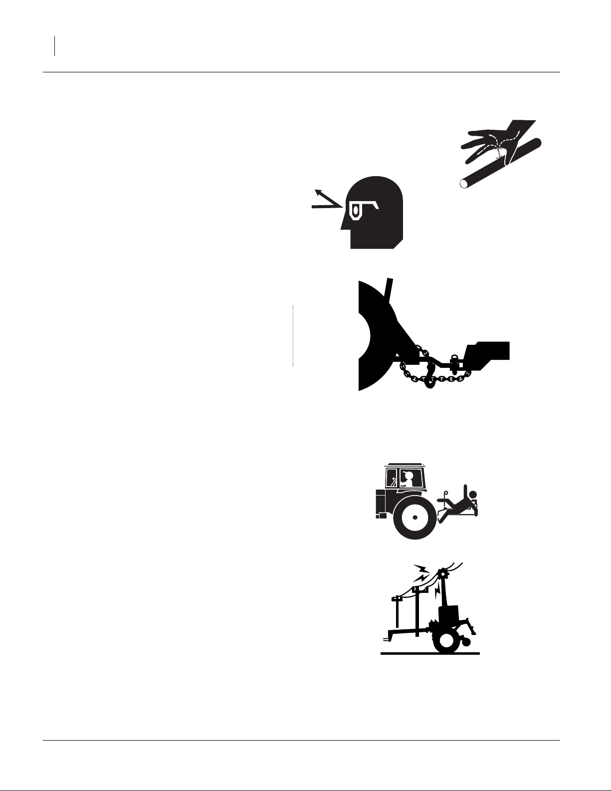
Avoid High Pressure Fluids
Escaping fluid under pressure can penetrate the skin,
causing serious injury.
▲ Avoid the hazard by relieving pressure before disconnecting
hydraulic lines.
▲ Use a piece of paper or cardboard, NOT BODY PARTS, to
check for suspected leaks.
▲ Wear protective gloves and safety glasses or goggles when
working with hydraulic systems.
▲ If an accident occurs, seek immediate medical attention
from a physician familiar with this type of injury.
Use A Safety Chain
▲ Use a safety chain to help control drawn machinery should
it separate from tractor drawbar.
▲ Use a chain with a strength rating equal to or greater than
the gross weight of towed machinery.
▲ Attach chain to tractor drawbar support or other specified
anchor location. Allow only enough slack in chain to permit
turning.
▲ Replace chain if any links or end fittings are broken,
stretched or damaged.
▲ Do not use safety chain for towing.
Keep Riders Off Machinery
Riders obstruct the operator’s view. Riders could be
struck by foreign objects or thrown from the machine.
▲ Never allow children to operate equipment.
▲ Keep all bystanders away from machine when folding/
unfolding, raising/lowering markers, raising/lowering
openers, and transporting.
Check for Overhead Lines
Drill markers contacting overhead electrical lines can
introduce lethal voltage levels on drill and tractor frames.
A person touching almost any metal part can complete
the circuit to ground, resulting in serious injury or death.
At higher voltages, electrocution can occur without direct
contact.
▲ Avoid overhead lines during seed loading/unloading and
marker operations.
196-522M 03/28/2012
E
Page 7

Great Plains Manufacturing, Inc. 3
Use Safety Lights and Devices
Slow-moving tractors and towed drills can create a hazard when driven on public roads. They are difficult to see,
especially at night.
▲ Use flashing warning lights and turn signals whenever driv-
ing on public roads.
▲ Use lights and devices provided with the drill.
Transport Machinery Safely
Maximum transport speed for drill is 20 mph (32 kph).
Rough terrains may require a slower speed. Sudden
braking can cause a towed load to swerve and upset.
▲ Do not exceed 20 mph (32 kph). Never travel at a speed
which does not allow adequate control of steering and stopping. Reduce speed if towed load is not equipped with
brakes.
▲ Comply with national, regional and local laws.
▲ Follow your tractor manual recommendations for maximum
hitch loads. Insufficient weight on tractor steering wheels
will result in loss of control.
▲ Carry reflectors or flags to mark drill in case of breakdown
on the road.
▲ Keep clear of overhead power lines and other obstructions
when transporting. Refer to transport dimensions under
“Specifications and Capacities” on page 89.
Wear Protective Equipment
▲ Wear protective clothing and equipment.
▲ Wear clothing and equipment appropriate for the job. Avoid
loose-fitting clothing.
▲ Because prolonged exposure to loud noise can cause hear-
ing impairment or hearing loss, wear suitable hearing protection such as earmuffs or earplugs.
▲ Because operating equipment safely requires your full
attention, avoid wearing entertainment headphones while
operating machinery.
03/28/2012 196-522M
Page 8
4 3S-4010HD and 3S-4010HDF Great Plains Manufacturing, Inc.
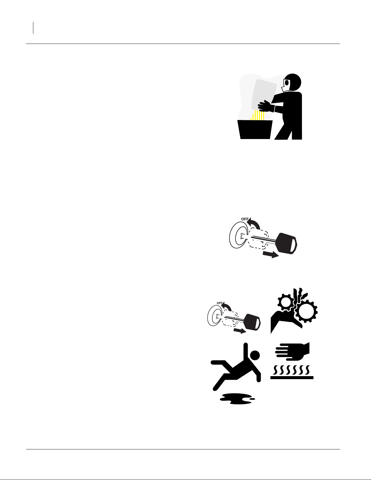
Handle Chemicals Properly
Agricultural chemicals can be dangerous. Improper use
can seriously injure persons, animals, plants, soil and
property.
▲ Do not use liquid treatments with drill.
▲ Read and follow chemical manufacturer’s instructions.
▲ Wear protective clothing.
▲ Handle all chemicals with care.
▲ Avoid inhaling smoke from any type of chemical fire.
▲ Never drain, rinse or wash dispensers within 100 feet (30m)
of a freshwater source, nor at a car wash.
▲ Store or dispose of unused chemicals as specified by chemi-
cal manufacturer.
▲ Dispose of empty chemical containers properly. Laws gen-
erally require power rinsing or rinsing three times, followed
by perforation of the container to prevent re-use.
Shutdown and Storage
▲ Clean out and safely store or dispose of residual chemicals.
▲ Secure drill using blocks and transport locks.
Lock up openers.
▲ Store in an area where children normally do not play.
Practice Safe Maintenance
▲ Understand procedure before doing work. Use proper tools
and equipment. Refer to this manual for additional information.
▲ Work in a clean, dry area.
▲ Put tractor in park, turn off engine, and remove key before
performing maintenance.
▲ Make sure all moving parts have stopped and all system
pressure is relieved.
▲ Disconnect battery ground cable (-) before servicing or
adjusting electrical systems or before welding on drill.
▲ Inspect all parts. Make sure parts are in good condition and
installed properly.
▲ Remove buildup of grease, oil or debris.
▲ Remove all tools and unused parts from drill before opera-
tion.
196-522M 03/28/2012
E
Page 9
Great Plains Manufacturing, Inc. 5
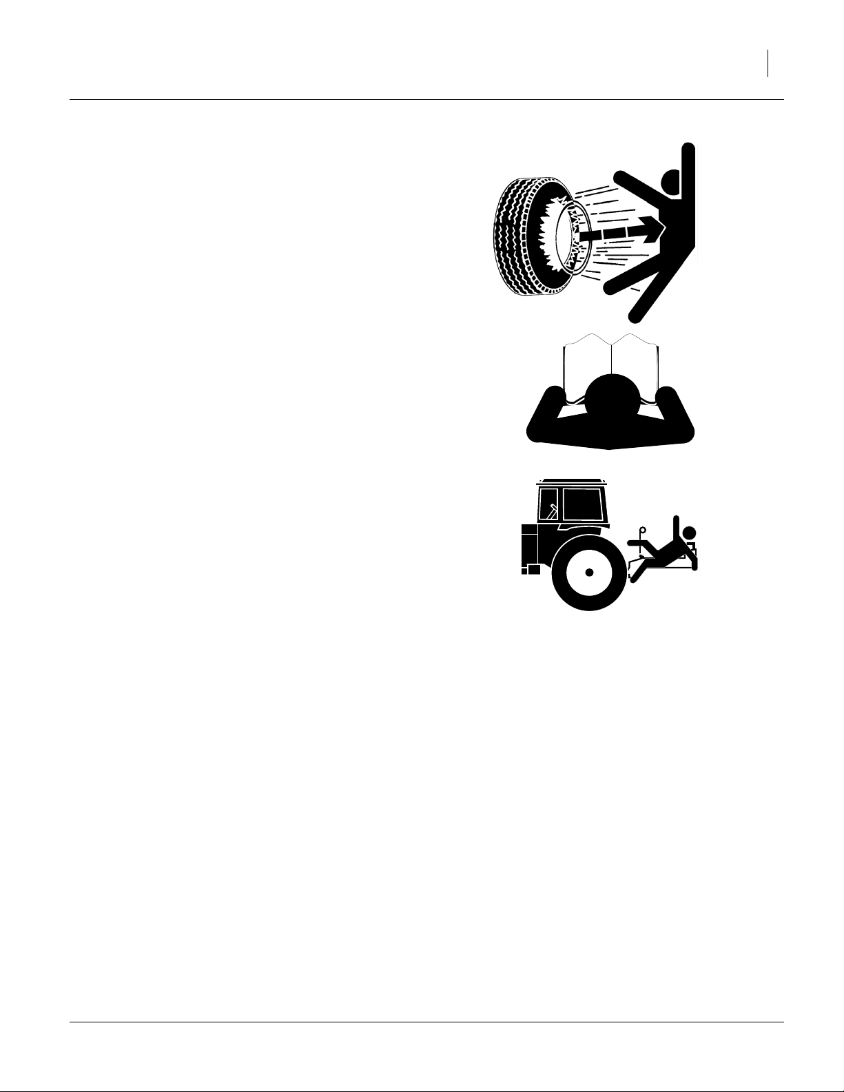
Tire Safety
Tire changing can be dangerous and should be performed by trained personnel using correct tools and
equipment.
▲ When inflating tires, use a clip-on chuck and extension hose
long enough for you to stand to one side–not in front of or
over tire assembly. Use a safety cage if available.
▲ When removing and installing wheels, use wheel-handling
equipment adequate for weight involved.
Safety At All Times
Thoroughly read and understand the instructions in this
manual before operation. Read all instructions noted on
the safety decals.
▲ Be familiar with all drill functions.
▲ Operate machinery from the driver’s seat only.
▲ Do not leave drill unattended with tractor engine running.
▲ Do not dismount a moving tractor. Dismounting a moving
tractor could cause serious injury or death.
▲ Do not stand between the tractor and drill during hitching.
▲ Keep hands, feet and clothing away from power-driven
parts.
▲ Wear snug-fitting clothing to avoid entanglement with mov-
ing parts.
▲ Watch out for wires, trees, etc., when folding and raising
drill. Make sure all persons are clear of working area.
▲ Do not turn tractor too tightly, causing drill to ride up on
wheels. This could cause personal injury or equipment
damage.
End of <safety topics>
03/28/2012 196-522M
Page 10
6 3S-4010HD and 3S-4010HDF Great Plains Manufacturing, Inc.
Safety Reflectors and Decals
Your drill comes equipped with all lights, safety reflectors
and decals in place. They were designed to help you
safely operate your drill.
▲ Read and follow decal directions.
▲ Keep lights in operating condition.
▲ Keep all safety decals clean and legible.
▲ Replace all damaged or missing decals. Order new decals
from your Great Plains dealer. Refer to this section for
proper decal placement.
▲ When ordering new parts or components, also request cor-
responding safety decals.
To install new decals:
1. Clean the area on which the decal is to be placed.
3. Peel backing from decal. Press firmly on surface,
being careful not to cause air bubbles under decal.
FigureSpacer:
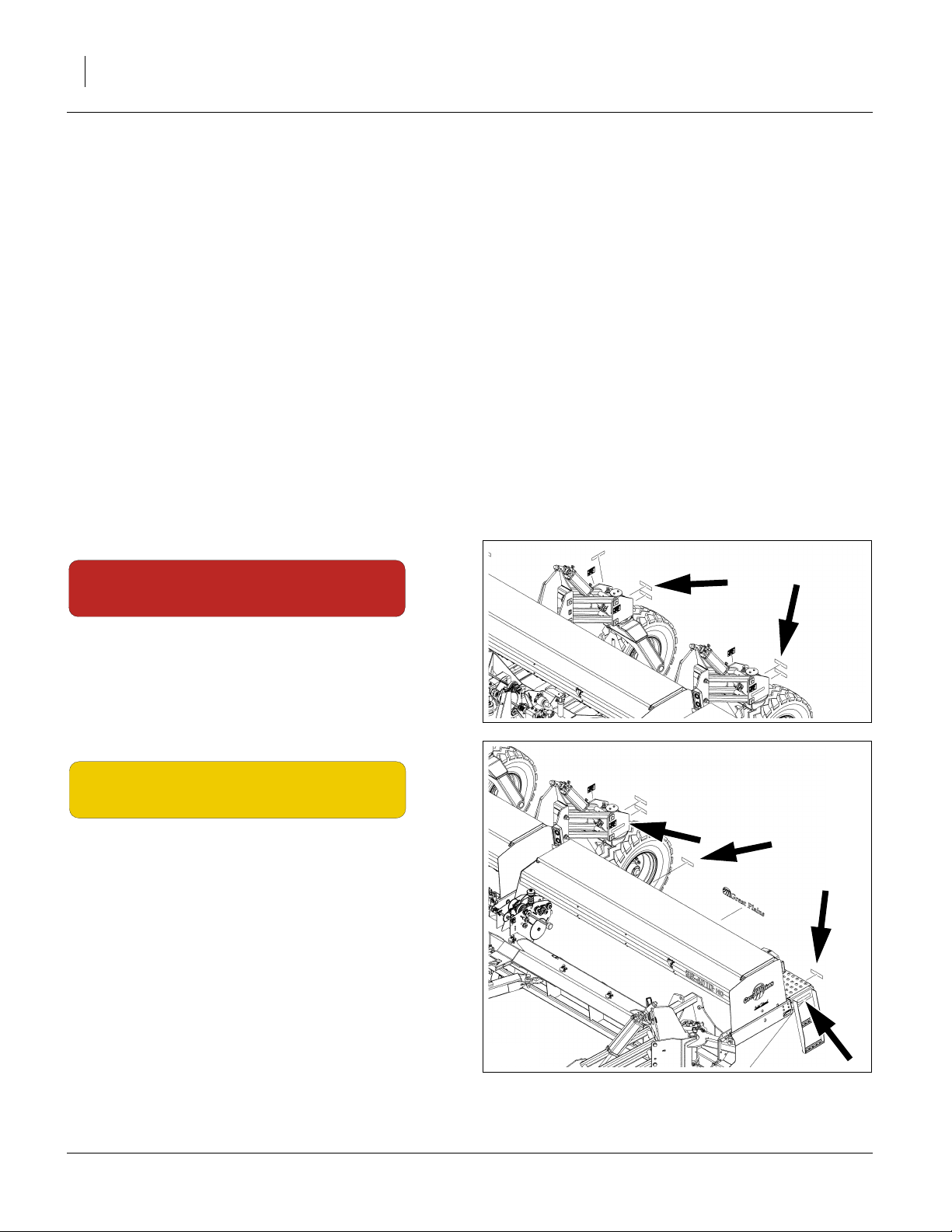
Red Reflectors
838-266C
rear face of rear casters;
2 total
FigureSpacer:
Amber Reflectors
838-265C
outside face of rear casters,
rear face, inside ends, wing walkboards,
rear face, outside ends, wing walkboards,
outside face of wing walkboards;
8 total
igureSpacer:
29122
FigureSpacer:
29122
196-522M 03/28/2012
E
Page 11
Great Plains Manufacturing, Inc. 7
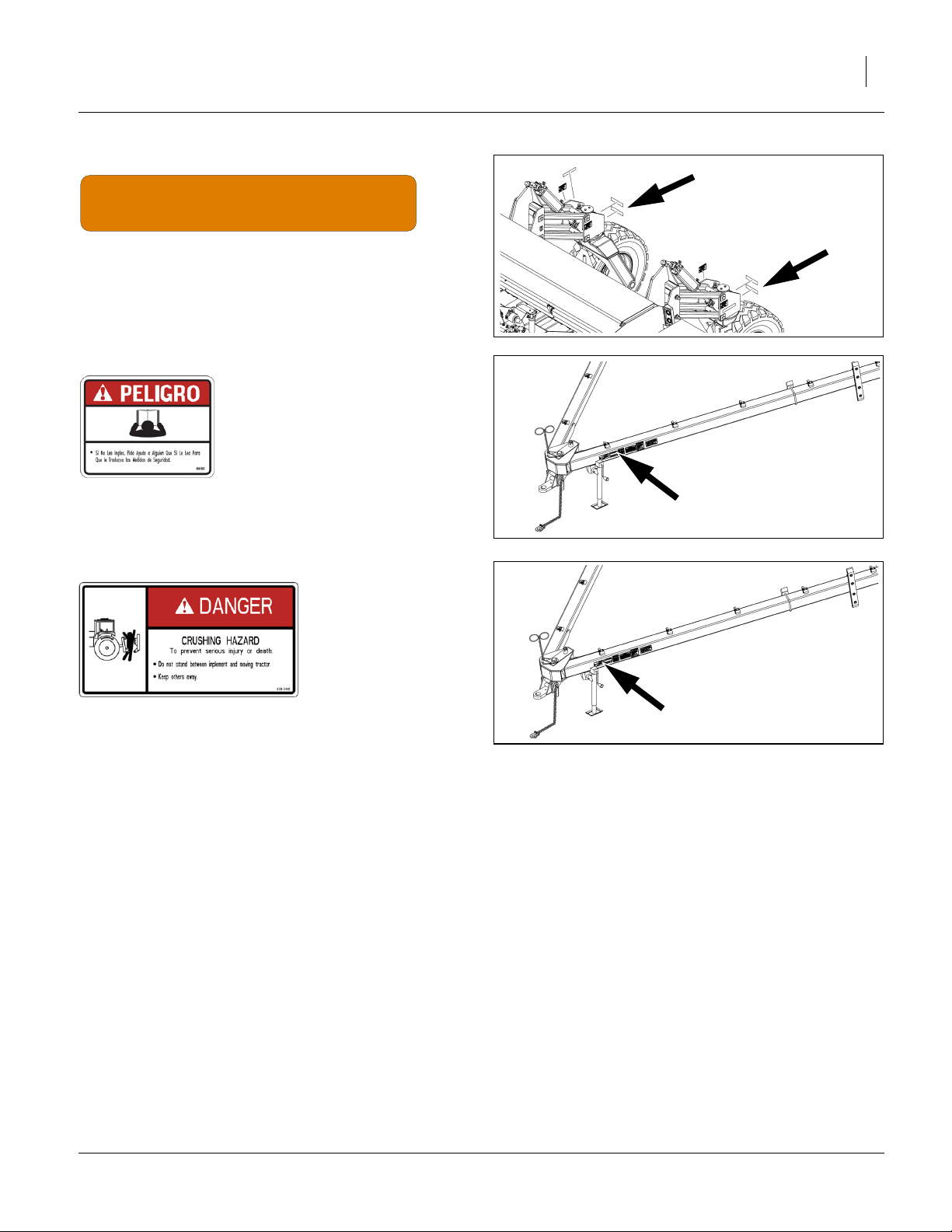
Daytime Reflectors
838-267C
rear face, rear casters, below red reflectors;
2 total
FigureSpacer:
29122
FigureSpacer:
Danger: Cannot Read English
818-557C
On outside of left tongue near hitch;
1 total
FigureSpacer:
Danger: Pinch/Crush Hazard
818-590C
On outside of left tongue near hitch;
1 total
FigureSpacer:
FigureSpacer:
29122
FigureSpacer:
29122
03/28/2012 196-522M
Page 12
8 3S-4010HD and 3S-4010HDF Great Plains Manufacturing, Inc.
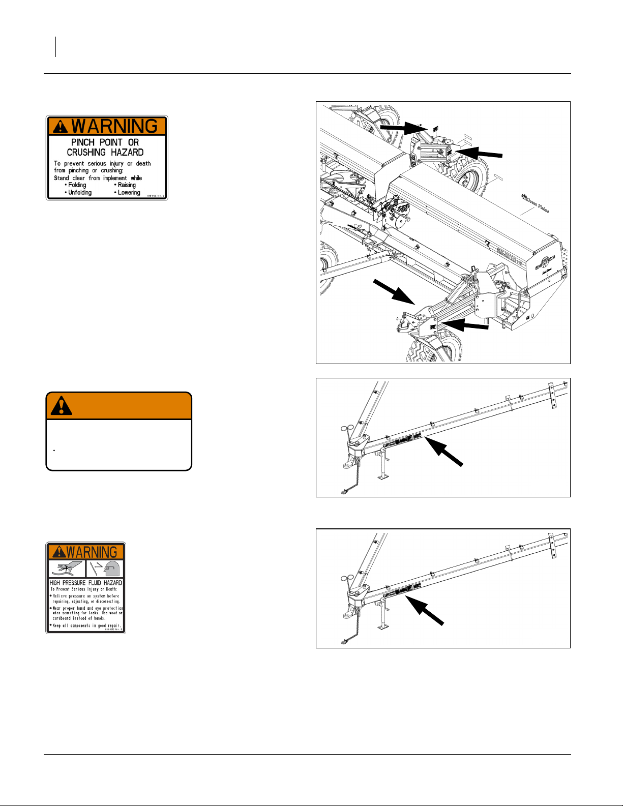
Warning: Pinch/Crush Hazard
818-045C
inside and outside faces, all caster pivots;
8 total
FigureSpacer:
Warning: Excessive Speed Hazard
WARNING
EXCESSIVE SPEED HAZARD
To Prevent Serious Injury or Death:
Do Not exceed 20 mph maximum transport
speed. Loss of vehicle control and/or machine
can result.
818-188C
On outside of left tongue near hitch;
1 total
FigureSpacer:
Warning: High Pressure Fluid
818-339C
On outside of left tongue near hitch;
1 total
FigureSpacer:
818-188C Rev. C
FigureSpacer:
29122
FigureSpacer:
29122
FigureSpacer:
29122
196-522M 03/28/2012
E
Page 13
Great Plains Manufacturing, Inc. 9
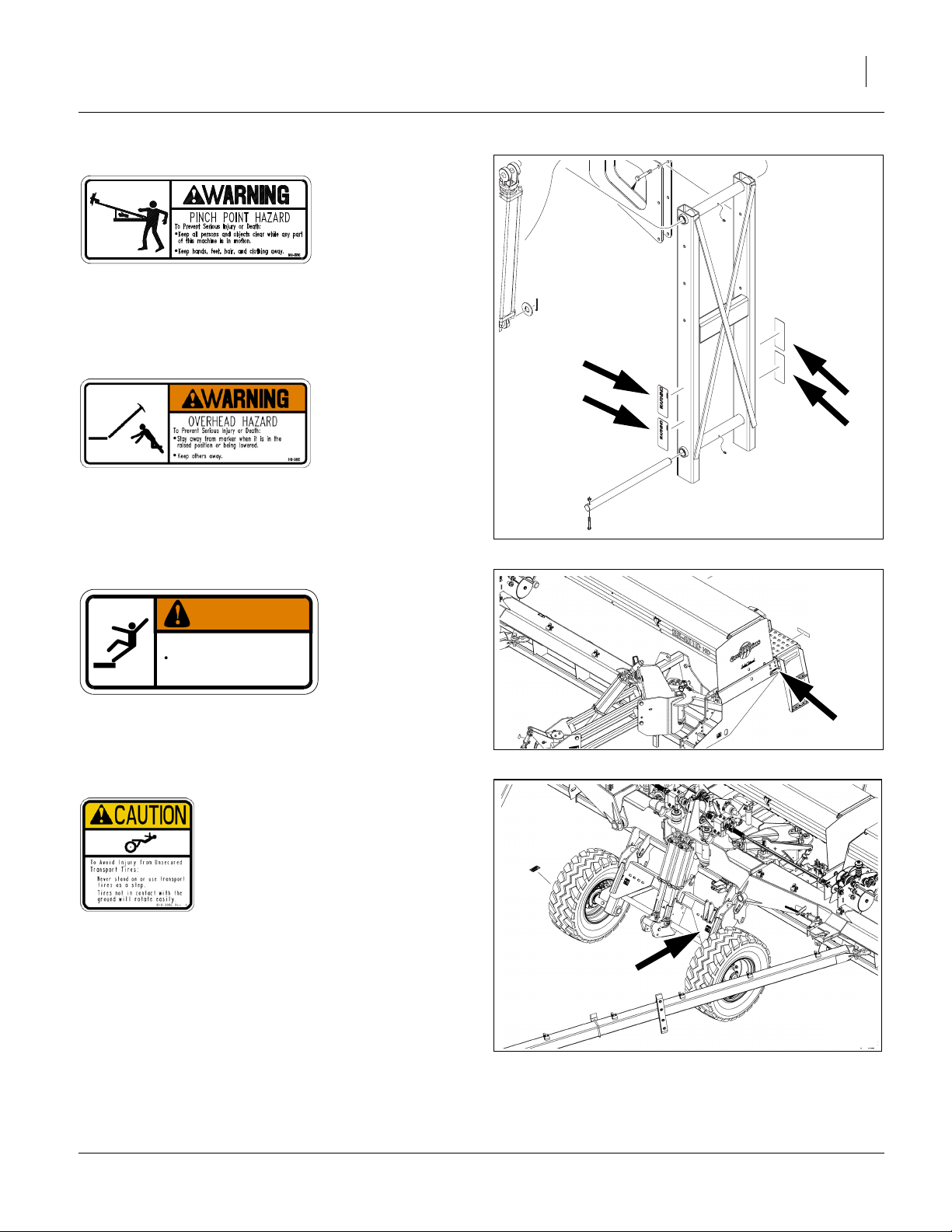
Warning Marker Pinch Point (Option)
818-579C
on either side of inner marker arm,
two each marker installed;
2 or 4 total
Warning Overhead Marker (Option)
818-580C
on either side of inner marker arm,
two each marker installed;
2 or 4 total
FigureSpacer:
Warning: Falling Hazard
FigureSpacer:
20287
FigureSpacer:
27010
WARNING
To avoid serious injury or death:
Watch your step when climbing ladder or
walking on walkboard.
838-102C
Top forward at each walkboard ladder;
2 total
FigureSpacer:
Caution: Tires Not A Step
818-398C
Top face, each side of rockshaft;
2 total
FigureSpacer:
838-102C
FigureSpacer:
29122
03/28/2012 196-522M
Page 14
10 3S-4010HD and 3S-4010HDF Great Plains Manufacturing, Inc.
F
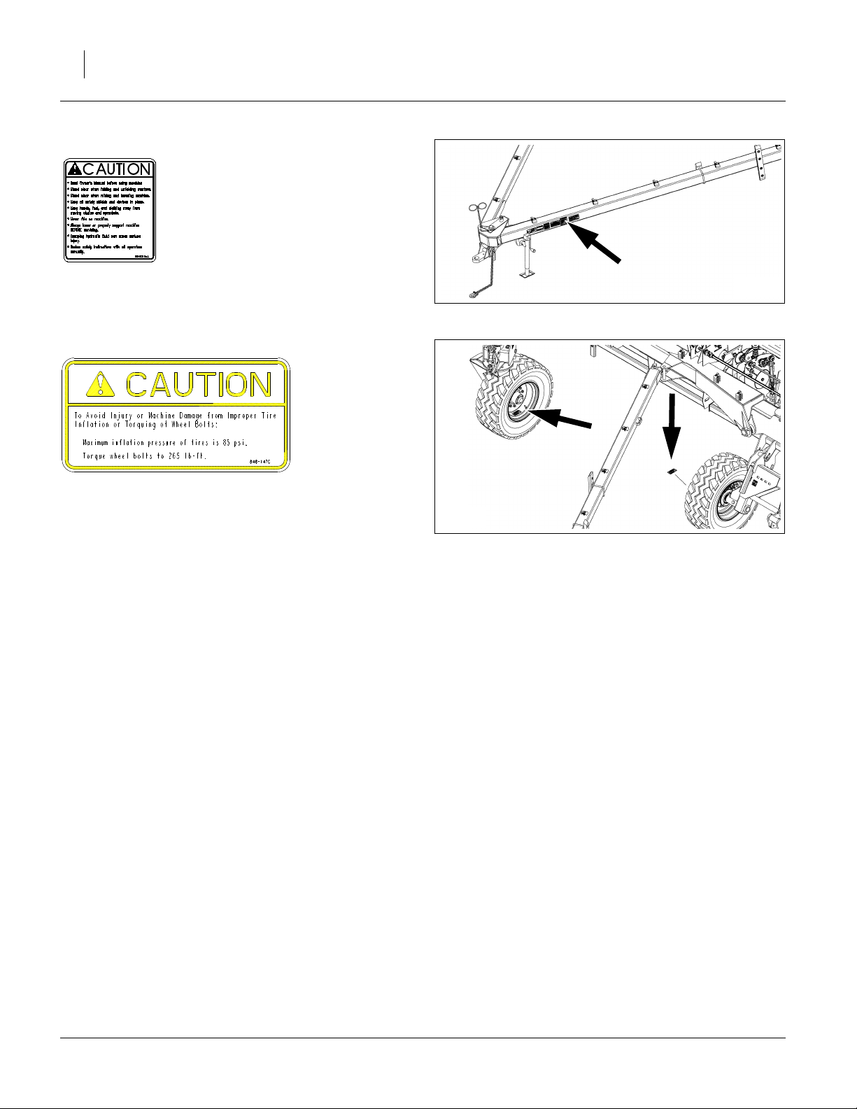
Caution: General
818-587C
On outside of left tongue near hitch;
1 total
FigureSpacer:
Caution: 85 PSI Tire Pressure
848-147C
On rim of each wheel;
6 total
End of “Safety Reflectors and Decals” End of “Important Safety Information”
igureSpacer:
29122
FigureSpacer:
29122
196-522M 03/28/2012
E
Page 15
Great Plains Manufacturing, Inc. Introduction 11
Introduction
Great Plains welcomes you to its growing family of new
product owners. Your 3-Section 40-Foot Heavy Duty Drill
has been designed with care and built by skilled workers
using quality materials. Proper setup, maintenance, and
safe operating practices will help you get years of satisfactory use from the machine.
Document Family
196-522M Operator Manual (this document)
196-522P 3S-4010HD/HDF Parts Manual
196-522B Seed Rate Manual
Description of Unit
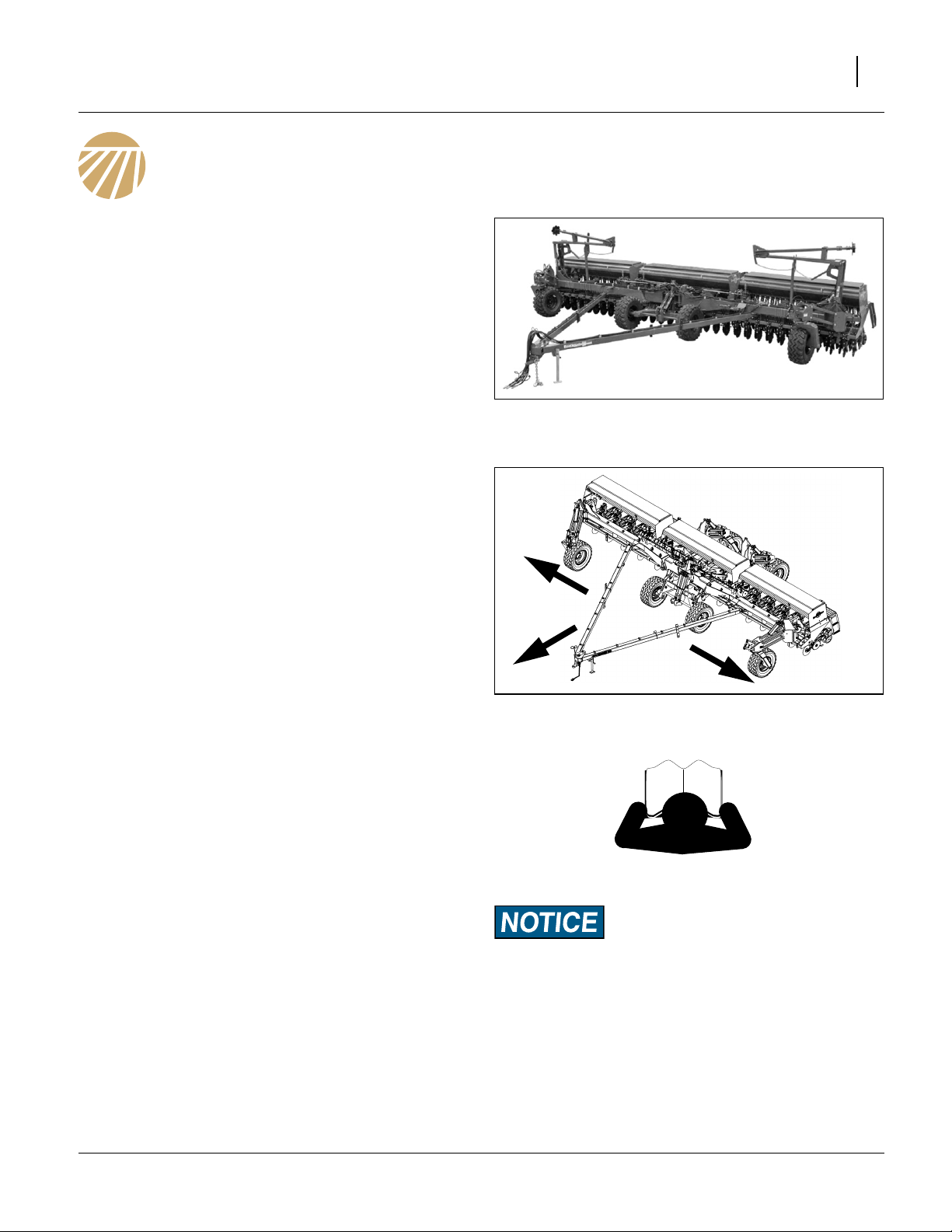
The 3S-4010HD/HDF is a pull-type 3-section fluted feed
folding drill with a working width of 40 feet (12.2m) and
10HD Series Heavy Duty parallel-arm double disk openers. Opener disks make a seed bed, and seed tubes
between the disks place seed in the furrow. Press
wheels following the disks close the furrow and gauge
opener seeding depth. Opener bodies are independently
adjustable for seeding depth and row unit down-force.
FigureSpacer:
R
Figure 1
3S-4010HD with Optional Markers
29072
Intended Usage
Use this drill to seed production-agriculture crops in no
till or minimum tillage applications. Do not modify the drill
for use with attachments, accessories or uses other than
those specified by Great Plains.
Models Covered
Seed-only models:
3S4010HD-4810 48 row 10in (25cm)
3S4010HD-6475 64 row 7.5in (19cm)
Fertilizer models:
3S4010HDF-4810 48 row 10in (25cm)
3S4010HDF-6475 64 row 7.5in (19cm)
Using This Manual
This manual familiarizes you with safety, assembly, operation, adjustments, troubleshooting, and maintenance.
Read this manual and follow the recommendations to
help ensure safe and efficient operation.
The information in this manual is current at printing.
Some parts may change to assure top performance.
Definitions
The following terms are used throughout this manual.
Right-hand and left-hand as used in this manual are
determined by facing the direction the machine will travel
while in use unless otherwise stated.
FigureSpacer:
L
.tif
600 dpi
Paragraphs in this format present a crucial point of information
related to the current topic. Read and follow the directions to:
- remain safe,
- avoid serious damage to equipment and
- ensure desired field results.
Note: Paragraphs in this format provide useful informa-
tion related to the current topic.
Figure 2
Left/Right Notation
29121
03/28/2012 196-522M
Page 16

12 3S-4010HD and 3S-4010HDF Great Plains Manufacturing, Inc.
Owner Assistance
If you need customer service or repair parts, contact a
Great Plains dealer. They have trained personnel, repair
parts and equipment specially designed for Great Plains
products.
Refer to Figure 3
Your drill’s parts were specially designed and should only
be replaced with Great Plains parts. Always use the
serial and model number when ordering parts from your
Great Plains dealer. The serial-number plate is located
on the front face, left end, of the center section opener
tool bar.
Record your drill model and serial number here for quick
reference:
Model Number:__________________________
Serial Number: __________________________
Your Great Plains dealer wants you to be satisfied with
your new drill. If you do not understand any part of this
manual or are not satisfied with the service received,
please take the following actions.
1. Discuss the matter with your dealership service
manager. Make sure they are aware of any problems
so they can assist you.
2. If you are still unsatisfied, seek out the owner or general manager of the dealership.
For further assistance write to:
FigureSpacer:
Figure 3
Serial Number Plate
27179
Product Support
Great Plains Mfg. Inc., Service Department
PO Box 5060
Salina, KS 67402-5060
785-823-3276 End of “Introduction”
196-522M 03/28/2012
E
Page 17
Great Plains Manufacturing, Inc. Preparation and Setup 13
Preparation and Setup
This section helps you prepare your tractor and drill for
use. Before using the drill in the field, you must hitch the
drill to a suitable tractor and also setup the drill.
Initial Setup
Prior to first use, see “Install Clutch Switch Module in
Cab” on page 106. See that manual section for other
Options that may not have been factory- or dealerinstalled.
Pre-Setup Checklist
1. Read and understand “Important Safety Information” on page 1.
2. Check that all working parts are moving freely, bolts
are tight, and cotter pins are spread.
3. Check that all grease fittings are in place and lubricated. See “Lubrication” on page 75.
4. Check that all safety decals and reflectors are correctly located and legible. Replace if damaged. See
“Safety Reflectors and Decals” on page 6.
5. Inflate tires to pressure recommended and tighten
wheel bolts as specified. “Appendix A - Reference
Information” on page 89.
Hitching to Tractor
Crushing Hazard:
You may be severely injured or killed by being crushed
between the tractor and drill. Do not stand or place any part of
your body between machines being hitched. Stop tractor
engine and set park brake before installing hitch pin.
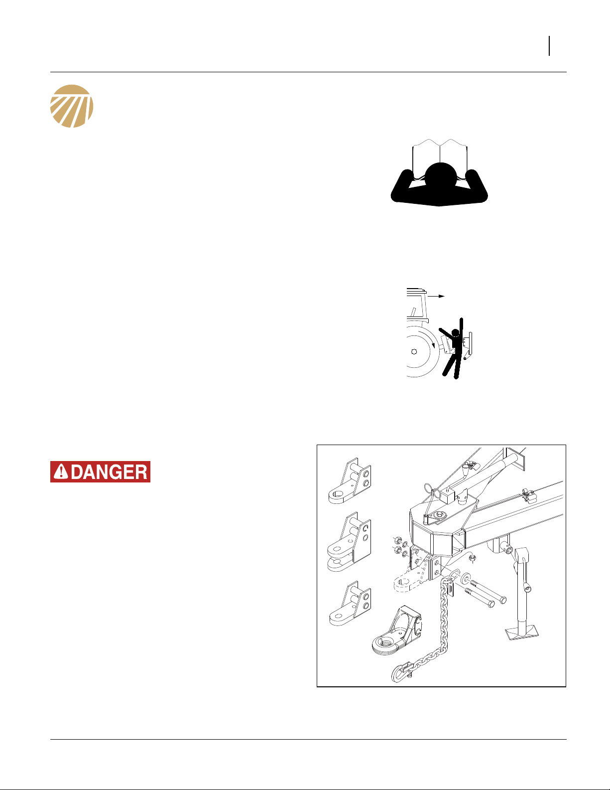
Choose a drill-hitch option (page 83) that is compatible
with your tractor drawbar.
The 3S-4010HD/HDF has four hitch options:
• a clevis hitch,
• a small-hole, single-strap hitch,
• a large-hole, single-strap hitch, or;
• a large cast strap hitch.
Always use a locking-style hitch pin sized to match the
holes in the hitch and drawbar, and at least 1
in diameter.
1
⁄
in (3.8cm)
2
FigureSpacer:
Figure 4
Hitch Options
29182
03/28/2012 196-522M
Page 18
14 3S-4010HD and 3S-4010HDF Great Plains Manufacturing, Inc.
Refer to Figure 5
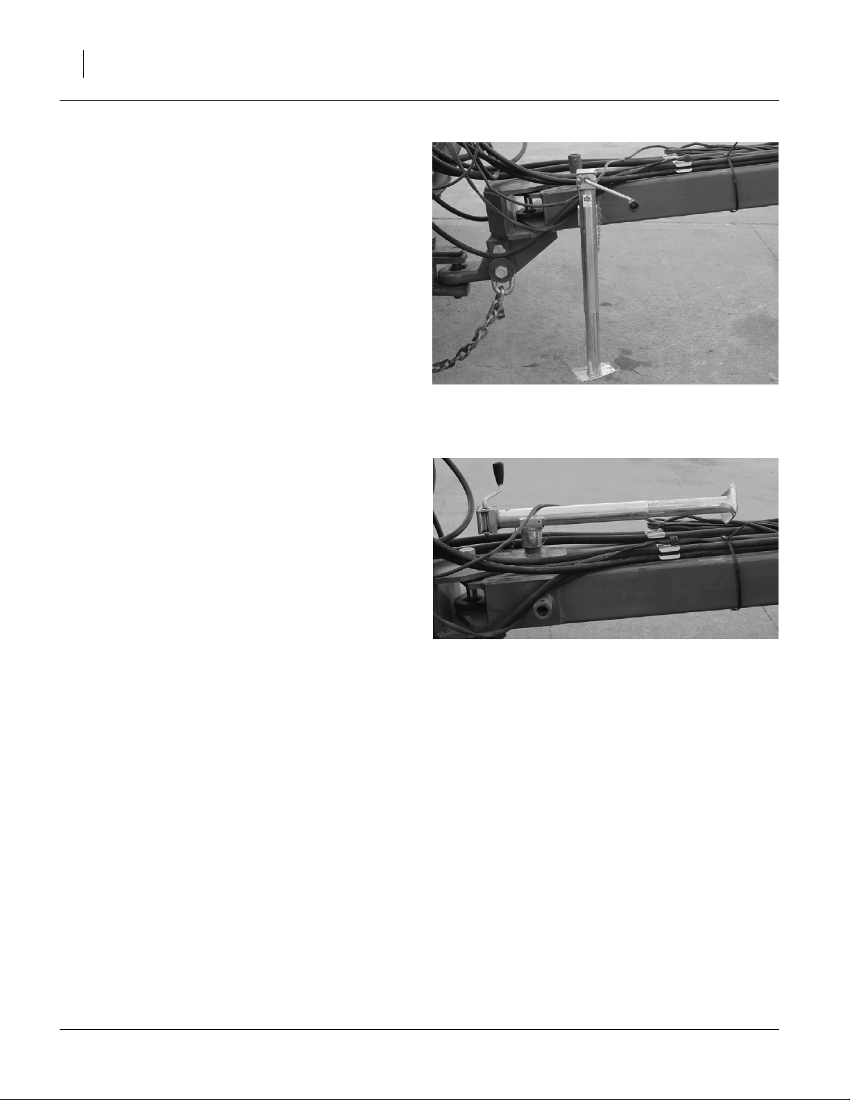
1. Adjust the drill hitch to match your tractor-drawbar
height, using crank of tongue jack on side of tongue.
Note: The precise height is not critical, as the drill leveling
is set at the mainframe and is independent of
tongue level.
Note: The hitch may be mounted inverted if necessary,
but always have two (2) bolts in two holes of both
tongue and hitch.
2. Securely attach safety chain to an anchor on a tractor capable of pulling the drill.
FigureSpacer:
Refer to Figure 6
3. Use crank to raise jack foot. Remove pin and jack.
4. Store jack on top of tongue.
FigureSpacer:
FigureSpacer:
100%
Figure 5
Drill Hitched
Figure 6
Jack in Storage Location
20273
20272
196-522M 03/28/2012
E
Page 19
Great Plains Manufacturing, Inc. Preparation and Setup 15
Tractor Electrical Connections
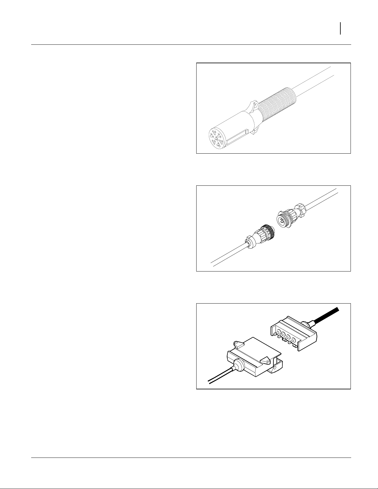
Lighting Harness
Refer to Figure 7
Plug drill electrical lead into tractor seven-pin connector.
If your tractor is not equipped with a seven-pin connector,
contact your dealer for installation.
FigureSpacer:
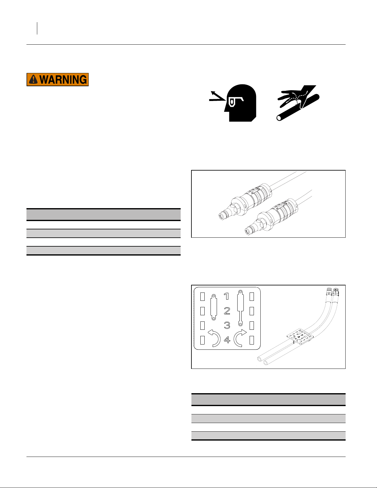
Electric Clutch Harness
Refer to Figure 8
Mate the connector for the cab clutch control.
FigureSpacer:
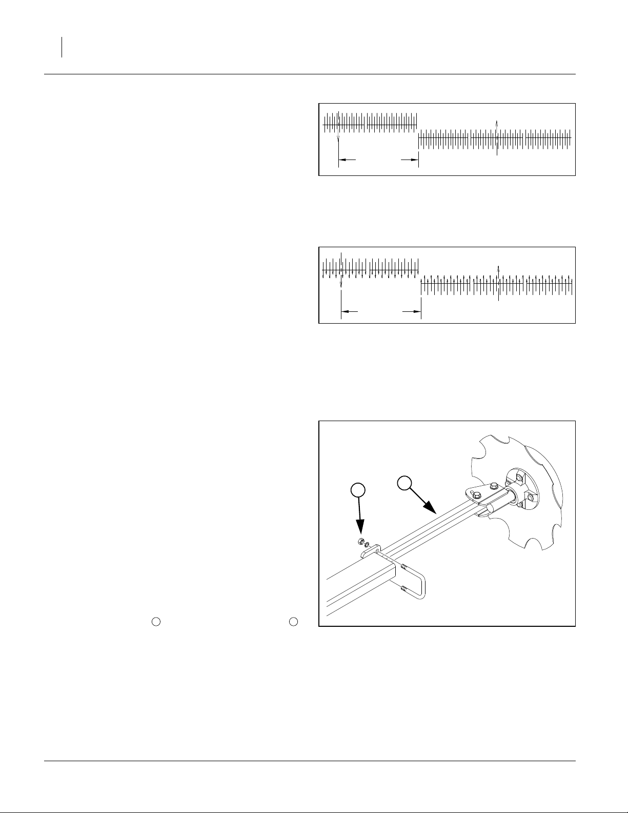
Shaft Monitor Harness (Option)
Refer to Figure 9
If the drill is equipped with the optional shaft monitor,
mate the connector for the cab display.
See “Shaft Monitor” on page 83 for ordering information.
FigureSpacer:
FigureSpacer:
Figure 7
Lighting Connector
Figure 8
Section Clutch Connector
26467
26469
FigureSpacer:
Figure 9
26468
Shaft Monitor Connector
03/28/2012 196-522M
Page 20
16 3S-4010HD and 3S-4010HDF Great Plains Manufacturing, Inc.
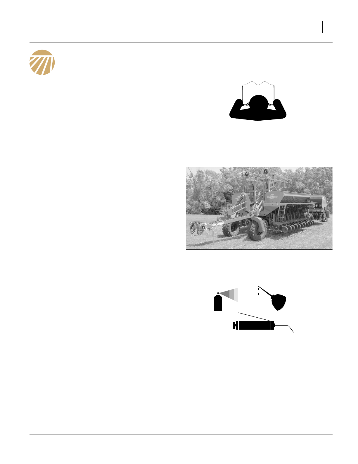
Tractor Hydraulic Hose Hookup
High Pressure Fluid Hazard:
Only trained personnel should work on system hydraulics!
Escaping fluid under pressure can have sufficient pressure to
penetrate the skin, causing serious injury. Avoid the hazard by
relieving pressure before disconnecting hydraulic lines. Use a
piece of paper or cardboard, NOT BODY PARTS, to check for
leaks. Wear protective gloves and safety glasses or goggles
when working with hydraulic systems. If an accident occurs,
seek immediate medical attention from a physician familiar
with this type of injury.
Refer to Figure 10
Current Style Color Coded Hose Handles
Great Plains hydraulic hoses have color coded handle
grips to help you hookup hoses to your tractor outlets.
Hoses that go to the same remote valve are marked with
the same color.
Color Hydraulic Function
Blue Lift Cylinders
Gray Fold Cylinders
Green Lock Cylinders
*note Markers (Optional)
Note: Markers are normally on Fold circuit.
To distinguish hoses on the same hydraulic circuit, refer
to the symbol molded into the handle grip. Hoses with an
extended-cylinder symbol feed cylinder base ends.
Hoses with a retracted-cylinder symbol feed cylinder rod
ends.
Older Style Hoses with Color Ties
Refer to Figure 11
Hoses that go to the same remote valve are marked with
the same color tie.
To distinguish hoses on the same hydraulic circuit, refer
to plastic hose label. The hose under an extended-cylinder symbol feeds a cylinder base end. The hose under a
retracted-cylinder symbol feeds a cylinder rod end.
1. Connect transport-lift hoses to tractor remote valve.
2. Connect fold hoses to tractor remote valve.
3. Connect lock hoses to tractor remote valve.
4. Connect marker hoses to tractor remote valve.
FigureSpacer:
Figure 10
Color Coded Hose Grips
FigureSpacer:
Figure 11
FigureSpacer:
FigureSpacer:
Older Style Hose with Label
Color Hydraulic Function
Blue Lift Cylinders
White Fold Cylinders
Orange Lock Cylinders
Yellow Markers (Optional)
31733
817-348c
17641
196-522M 03/28/2012
E
Page 21

Great Plains Manufacturing, Inc. Preparation and Setup 17
Hydraulic Charge
The hydraulic system was fully charged and bled when
the drill left the factory. If any changes were made prior to
delivery (such as installing markers), or there is any
question about the status of the system, see “Bleeding
Hydraulics” on page 64.
After some use, it is normal for the lift cylinders to get out
of phase. If one or more sections are not fully lifting, or
are lifting to different heights, see “Re-phasing Lift Sys-
tem” on page 20.
Drill Level
A new drill has been aligned at the factory and should
not require adjustment prior to first use. Level needs to
be checked periodically, and possibly adjusted.
See “Leveling Drill” on page 66
•“Side-to-Side Level” on page 66
•“Front-to-Back Level” on page 67
•“Section Alignment” on page 68
03/28/2012 196-522M
Page 22
18 3S-4010HD and 3S-4010HDF Great Plains Manufacturing, Inc.
Marker Setup
If markers were ordered with the drill, they were factoryinstalled. If they were ordered separately, install them
now, per the instructions included with the markers.
1. Review “Marker Operation” on page 30.
2. Bleed the marker circuit. See “Bleeding Marker
Hydraulics” on page 73.
3. If you know that your conditions require a specific
marker disk orientation, change it now. See “Marker
Disk Adjustment” on page 54.
4. Adjust marker speed. See “Marker Speed” on
page 73.
5. Set the initial marker extension, below.
6. Fold the markers.
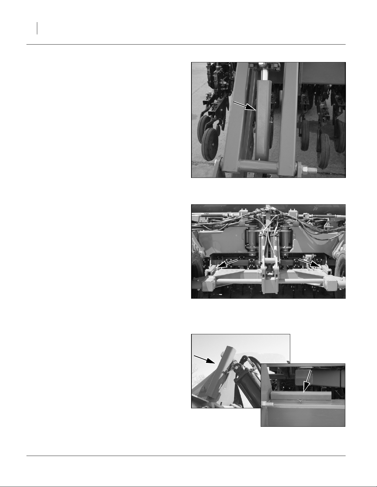
Initial Marker Extension
Marker Extension is the distance from the centerline of
the outboard row unit on each side to the centerline of
the mark left in the ground by the marker.
The 3S-4010HD and 3S-4010HDF is symmetrical, and
the values are the same on each side and independent
of next pass direction. On a dual-marker drill, set each
side.
To change marker extension:
If this is not the first adjustment to marker length.
1. Position drill on level ground and lower to planting
position.
2. Fully extend a marker.
3. If you plan to change the marker blade angle or
invert the blade, make that adjustment now (see
page 54).
4. Pull forward several feet to leave a mark.
5. Sighting along a line parallel to a tool bar, measure
the distance from the outside row unit centerline
(opener discs or furrow) to the mark. If the distance
matches the suggested value above, no marker
extension adjustment is needed.
FigureSpacer:
FigureSpacer:
245.75 in
624.2 cm
Figure 12 - Marker Extension
for 7.5in (19cm) Rows
245.0 in
622.3 cm
Figure 13 - Marker Extension
for 10in (25cm) Rows
1
2
20361
20361
6. Loosen U-bolt nuts securing outer marker tube .
7. Slide the tube in or out to change extension. Secure
the nuts.
1 2
FigureSpacer:
Figure 14
Adjust Marker Extension
18878
8. Pull forward and re-measure new mark. Return to
step 6 if further adjustment is needed.
End of “Preparation and Setup”
196-522M 03/28/2012
E
Page 23
Great Plains Manufacturing, Inc. Operating Instructions 19
Operating Instructions
This section covers general operating procedures. It
assumes that Setup items have been completed for the
drill.
Experience, machine familiarity and the following information will lead to efficient operation and good working
habits. Always operate farm machinery with safety in
mind.
General Description
All drill hydraulic functions are on separate circuits. Field
operations are entirely controlled from the tractor cab.
Planting Operation
Seed and fertilizer are delivered to the row units by gravity, from fluted feed meters powered by ground drive.
Material rate setup varies by box, but always includes a
rate handle/knob for fine control, and may include
sprocket pairings for coarse control. Meter rate selfadjusts for changes in ground speed.
Seeding stops when motion stops or the drill is raised.
A height switch on the drill controls meter drive clutches,
turning them on and off as the drill is lowered and raised.
A cab console switch box provides clutch control by drill
section for point row operation.
Seeding depth and furrow coverage are controlled by
row unit down pressure and depth adjustments.
FigureSpacer:
Figure 15
3S-4010HDF Folded
29183
Pre-Start Checklist
❑ Lubricate the drill as indicated under Lubrication,
“Maintenance and Lubrication” on page 60.
❑ Check the tires for proper inflation according to “Tire
Inflation Chart” on page 89.
❑ Check for worn or damaged parts and repair or
replace before going to the field.
❑ Check all nuts, bolts and screws. Tighten bolts as
specified on “Torque Values Chart” on page 90
❑ Check drill height switch on drill
03/28/2012 196-522M
Page 24
20 3S-4010HD and 3S-4010HDF Great Plains Manufacturing, Inc.
Raising and Lowering (Lift)
The drill Lift function is used only when the drill is
unfolded. The drill must be fully lifted and locked when
folded.
When unfolded, the lift function is used for headland
turns, adjustments and maintenance, and in preparation
for folding.
Raising
1. Operate the tractor lever for the Lift circuit to fully
extend the lift cylinders. Set lever to Neutral to hold
at lift. If raising for turns or short field moves, lift is
complete.
2. If lifting for adjustments, maintenance or in preparation for Fold, install lift locks.
FigureSpacer:
Lift Locks
Refer to Figure 16 and Figure 17
3. Remove lock channels from storage locations on the
rockshaft.
4. Install lock channels over extended lift cylinder rods.
Six cylinder rods total.
FigureSpacer:
Figure 16
Rear Lift Cylinder Lock
20264
Lowering
Lower drill only when fully unfolded.
1. Extend lift cylinders to fully raised (in case cylinders
have settled against lock channels). Set circuit lever
to neutral.
2. Remove lock channels and stow them at their storage locations.
3. Retract lift cylinders and fully lower drill.
Re-phasing Lift System
Over a period of normal use the cylinders may get out of
phase. This will cause some drill sections to run higher
than others. To re-phase cylinders:
1. Raise the drill completely and hold the hydraulic
remote lever on for several seconds until all cylinders
are fully extended. Do this every 3 or 4 times you
raise drill out of ground.
2. When all cylinders are fully extended, momentarily
reverse hydraulic remote lever to Retract height
(6.3cm) to maintain levelness.
1
⁄
in
2
FigureSpacer:
FigureSpacer:
Figure 17
Rockshaft Lock Channel
Figure 18
Lock Channel Storage
29081
20268
20269
196-522M 03/28/2012
E
Page 25
Great Plains Manufacturing, Inc. Operating Instructions 21
Folding
Pinch Point and Crushing Hazard:
To prevent serious injury or death:
▲ Always use transport locks when drill is folded.
▲ Fold only if hydraulics are bled free of air and fully charged
with hydraulic oil.
▲ Stay away from frame sections when they are being raised
or lowered.
▲ Keep away and keep others away when folding or unfolding
drill.
Fold the drill on level ground with the tractor in neutral.
FigureSpacer:
Figure 19 Tool Bar & Transport Lock
Cylinders
21845
21841
Clearance/Equipment Damage Risk:
The hitch-to-hitch length of the 3S-4010HD/HDF increases by
12 feet (3.7m) during folding. Allow at least 12 feet (3.7m) of
clearance ahead of and behind the drill when folding.
Tractor can move forward during folding, if tractor is in neutral with brakes released.
Center section of drill can move backward during folding if
tractor is in Park, has brakes set, or otherwise cannot move.
1. Raise drill with lift cylinders until cylinders are fully
extended.
2. Install lift locks. See “Raising” on page 20.
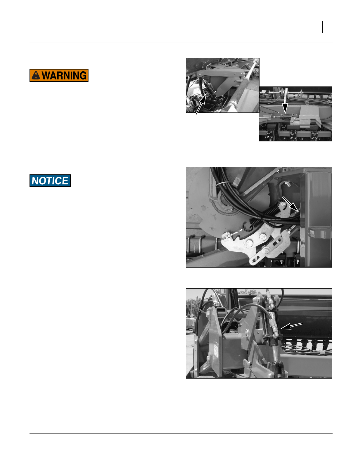
3. Retract the Lock cylinder circuit lever to:
disengage the tool bar lock,
disengage swivel locks,
disengage caster locks, and
enable the self-latching transport lock.
Set circuit to neutral.
4. Extend the Fold cylinder circuit lever to slowly fold
wings forward. The transport lock automatically captures the right wing tool bar for transport.
Note: It may be necessary to ease forward slightly with
the tractor to assist wings in folding completely.
FigureSpacer:
Figure 20
Swivel Lock Cylinder
27183
FigureSpacer:
Figure 21
29088
Caster Lock Cylinder
(Retract to Fold - Extend to Unfold)
03/28/2012 196-522M
Page 26
22 3S-4010HD and 3S-4010HDF Great Plains Manufacturing, Inc.
d
d
Unfolding
Unfold the drill on level ground with the tractor transmission in neutral.
1. Fold markers, if installed.
2. Extend the Lock circuit lever to:
enable the tool bar lock,
enable the swivel locks,
enable the caster locks, and
release the transport lock.
Set circuit to neutral.
3. Retract the Fold circuit to unfold drill.
The tool bar, swivel and caster locks automatically
engage, either at the completion of unfolding, or during next forward movement of the drill.
4. Extend the Lift circuit as needed to raise the lift cylinder bodies off their lock channels.
5. Remove lock channels from all six lift cylinders.
Store lock channels.
6. Lower drill. See “Lowering” on page 20.
Pinch Point and Crushing Hazard:
To prevent serious injury or death:
▲ Always use transport locks when drill is folded.
▲ Fold only if hydraulics are bled free of air and fully charge
with hydraulic oil.
▲ Stay away from frame sections when they are being raise
or lowered.
▲ Keep away and keep others away when folding or unfolding
drill.
The hitch-to-hitch length of the 3S-4010HD/HDF decreases by
12 feet (3.7m) during unfolding.
Keep all persons away from all drill wheels during unfolding.
Tractor can move backward during folding, if tractor is in neutral with brakes released.
FigureSpacer:
Lock-Out Hubs
To reduce wear on drive system components during
transport, the rockshaft gauge wheels can be locked-out
(disconnected) from the drive system.
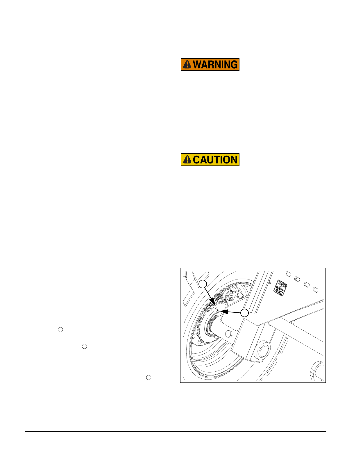
Hub Lock-Out
Refer to Figure 22 (which depicts the right rockshaft wheel
with the drive system engaged)
1. At each rockshaft wheel, locate the lock-out pin
receiver . Note that it has both shallow and deeper
1
detents.
2. Pull the cross-pin away from the sprocket, rotate
the pin
1
⁄
turn, and release into the shallow detents.
4
2
Hub Engagement
1. At each rockshaft wheel, pull the cross-pin away
from the sprocket, rotate the pin
into the deep detents.
Note: The pin usually does not fully seat immediately, but
does so during the next full rotation of the wheel.
1
⁄
turn, and release
4
2
Center section of drill can move forward during folding if tractor is in Park, has brakes set, or otherwise cannot move.
2
1
FigureSpacer:
Figure 22
Lock-Out Hub
29226
196-522M 03/28/2012
E
Page 27
Great Plains Manufacturing, Inc. Operating Instructions 23
Transport
Electrocution Hazard:
To prevent serious injury or death from electric shock, keep
clear of overhead power lines when transporting, folding,
unfolding or operating all drill components. Machine is not
grounded. At higher voltages, electrocution can occur without
direct contact.
Great Plains recommends transporting the drill empty.
Although designed for highway movement when loaded,
the additional weight of seed may cause the drill to
exceed the rated ability of the tractor, makes the drill
more difficult to control and stop, and increases wear on
tires and wheel bearings.
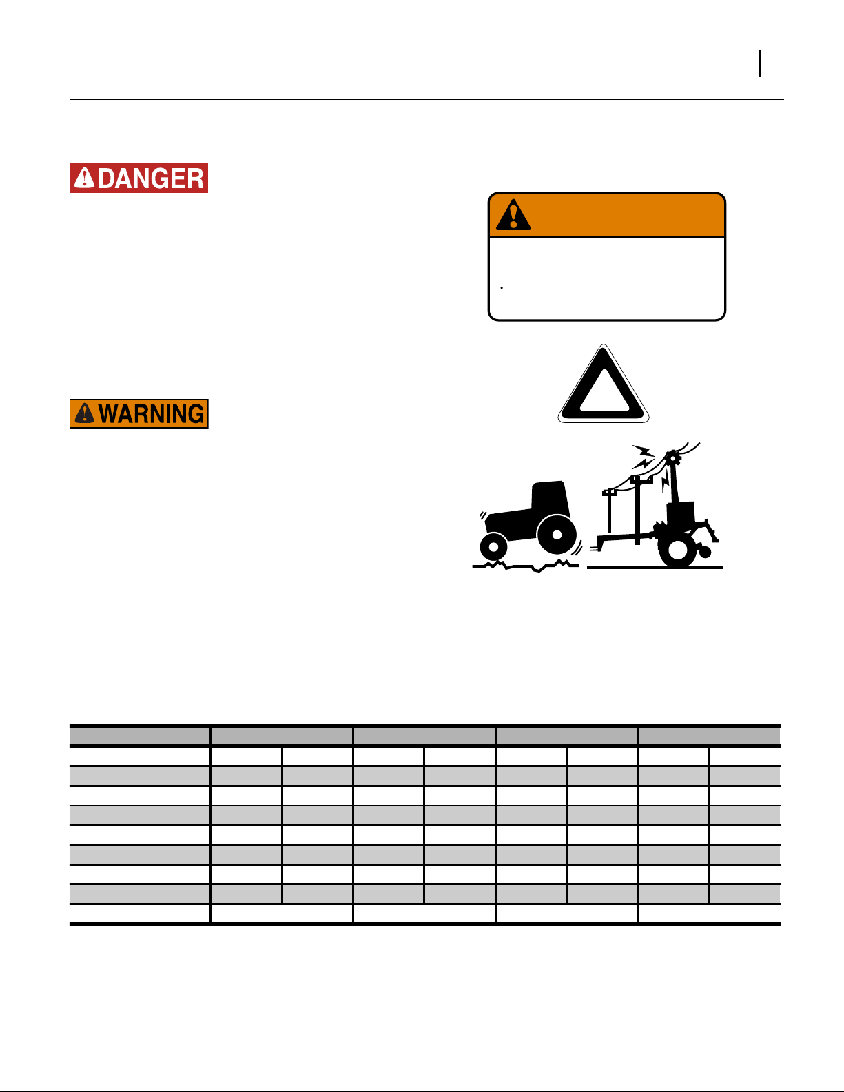
Loss of Control Hazard:
Towing the drill at high speeds or with a vehicle that is not
heavy enough can lead to loss of vehicle control. Loss of vehicle control can lead to serious road accidents, injury and
death. To reduce the hazard:
▲ Do not exceed 20 mph (32 kph).
WARNING
EXCESSIVE SPEED HAZARD
To Prevent Serious Injury or Death:
Do Not exceed 20 mph maximum transport
speed. Loss of vehicle control and/or machine
can result.
818-188C Rev. C
▲ Do not tow a drill that weighs more than 1.5 times the
weight of the towing vehicle. (The tractor must weigh at
2
least
⁄
or 67% of the drill weight - see table below.)
3
Transport Weights
In the table, the “Large Configuration” includes: 3 weight
kits, coulters, markers and Small Seeds (empty). If your
tractor is rated for more than the “Large Configuration”,
you may not need to determine the weight of your drill.
Approximate Transport Weights
3S4010HD-4810 3S4010HD-6475 3S4010HDF-4810 3S4010HDF-6475
Large Configuration 48700 lbs 22100 kg 51700 lbs 23500 kg 50100 lbs 22700 kg 53100 lbs 24100 kg
Base Drill 31600 lbs 14300 kg 33600 lbs 15200 kg 32100 lbs 14600 kg 34100 lbs 15500 kg
Add for Small Seeds 600 lbs 300 kg 600 lbs 300 kg 600 lbs 300 kg 600 lbs 300 kg
Add for Markers 1900 lbs 900 kg 1900 lbs 900 kg 1900 lbs 900 kg 1900 lbs 900 kg
Add for Coulters 3000 lbs 1400 kg 4000 lbs 1800 kg 3000 lbs 1400 kg 4000 lbs 1800 kg
Add for 3 Weight Kits 3400 lbs 1500 kg 3400 lbs 1500 kg 3400 lbs 1500 kg 3400 lbs 1500 kg
Add for Seed Load 8200 lbs 3700 kg 8200 lbs 3700 kg 4900 lbs 2200 kg 4900 lbs 2200 kg
Add for Fertilizer Load 0 lbs 0 kg 0 lbs 0 kg 4200 lbs 1900 kg 4200 lbs 1900 kg
Your Configuration
Note: These weights are approximate. They can vary by
hundreds of pounds depending on coulter type,
press wheel type, material density and aftermarket modifications.
03/28/2012 196-522M
Page 28

24 3S-4010HD and 3S-4010HDF Great Plains Manufacturing, Inc.
Pre-Transport Checklist
Before transporting the drill, check and observe the following items.
❑ Make sure the weight of the tractor equals or
exceeds 67% the drill.
❑ Marker Checklist Complete
Markers must be folded in transport carriers.
❑ Drill Folded and Locked
❑ Tires
Check that all tires are properly inflated as listed on
“Tire Inflation Chart” on page 89.
❑ Lock-Out Hubs
Disengage rockshaft wheels from drive system.
See “Lock-Out Hubs” on page 22.
❑ Bystanders
Check that no one is in the way before moving. Do
not allow any one to ride on the drill.
❑ Warning Lights
Always use tractor and drill warning lights when
transporting the drill.
❑ Clearance
Know the maximum dimensions of the drill in transport position and follow a route that provides adequate clearance from all obstructions, including
overhead lines.
See “Specifications and Capacities” on page 89.
❑ Stopping Distance
Allow sufficient stopping distance and reduce speed
prior to any turns or maneuvers. If transported full,
allow extra stopping distance.
❑ Road Rules
Comply with all national, regional and local laws
when transporting on public roads.
❑ Watch Traffic
The seed boxes obstruct a portion of your rear view.
Be prepared for sudden maneuvers from following
vehicles.
FigureSpacer:
Figure 23
Marker in Transport Cradle
29092
196-522M 03/28/2012
E
Page 29
Great Plains Manufacturing, Inc. Operating Instructions 25
Loading Materials
Fully loaded with dense seed, the drill weighs an additional 8294 lbs (3762 kg). Include this weight when
checking tractor capability.
Load slightly more material than needed, because consumption rates can vary between compartments even
though the furrow rates are identical.
Main Seed Box Loading
1. Check that all meter doors are positioned for the
seed size, and not set for clean-out. See “Position
Seed Cup Doors” in seed Rate Manual. If loading
prior to transport, set them to position 1 (smallest
seed).
2. Install or remove optional seed plugs as desired for
the row spacing planned. See “Seed Tube Plug
(Main Seeds)” on page 85.
3. If loading prior to transport, and calibration has not
yet been done, set Seed Rate Handle to 0. At 0, and
with the doors at 1, no seed can leak during transport.
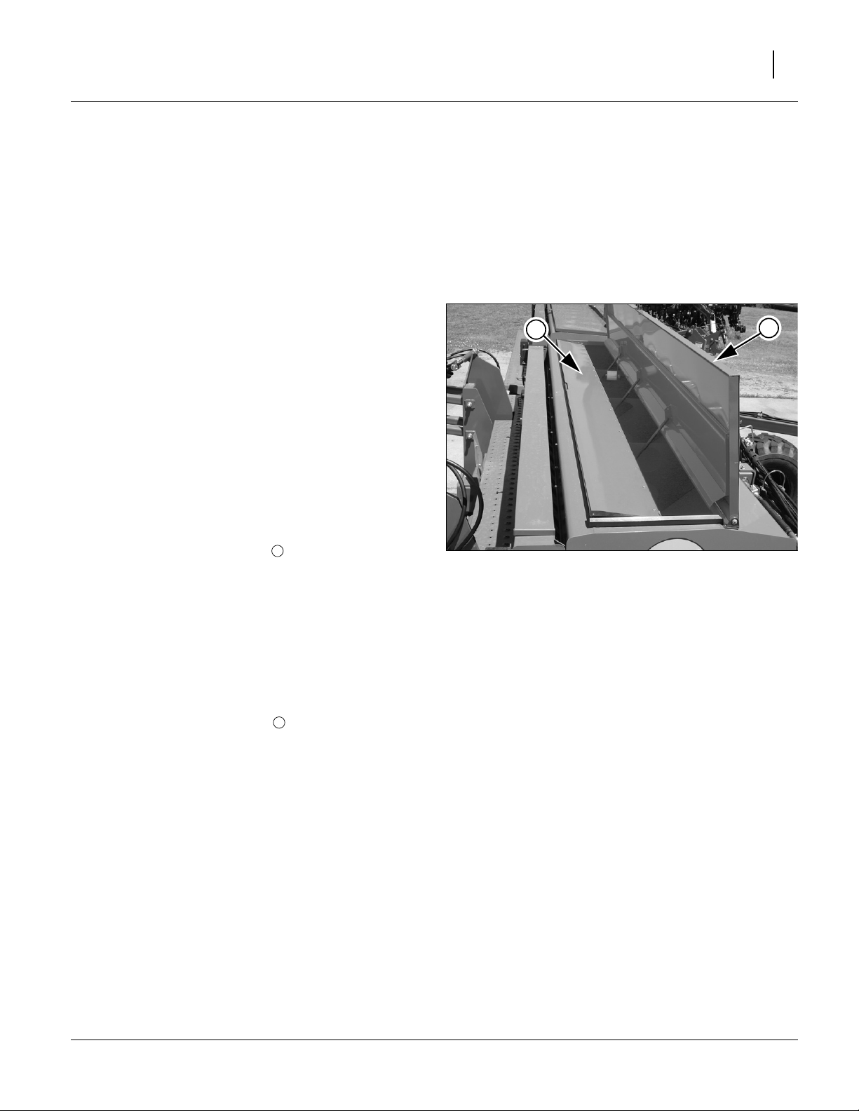
Refer to Figure 24
4. The main seed box lid handle is also a latch. It needs
to pivot up to release the lid .
1
5. On HDF (fertilizer-capable) drill models:
• Check that any offset box dividers are set to the
desired compartment ratio. See “Offset Box
Divider” on page 86.
• Check that the divider flap is set as desired (separate compartments, or all-seed). See “HDF Seed-
ing with Both Compartments” on page 26.
• If seeding only from the forward (seed) compartment, flip the top spill flap back to prevent seed
2
from entering the fertilizer compartment.
6. Take all necessary materials safety precautions if the
seed is treated.
7. Load seed evenly into compartments.
To reduce wear on unused boxes that may also be
present, remove final drive chain for Small Seeds box.
2
FigureSpacer:
Figure 24
Main Box Open for Seed
1
29082
03/28/2012 196-522M
Page 30
26 3S-4010HD and 3S-4010HDF Great Plains Manufacturing, Inc.
HDF Seeding with Both Compartments
A 3S-4010HDF drill can use the fertilizer compartment
for seed (which is still metered by the main seed box
meters).
1. Clean out both boxes. See “Main Seed Box Clean-
Out” on page 61 and “Fertilizer Box Clean-Out”on
page 61.
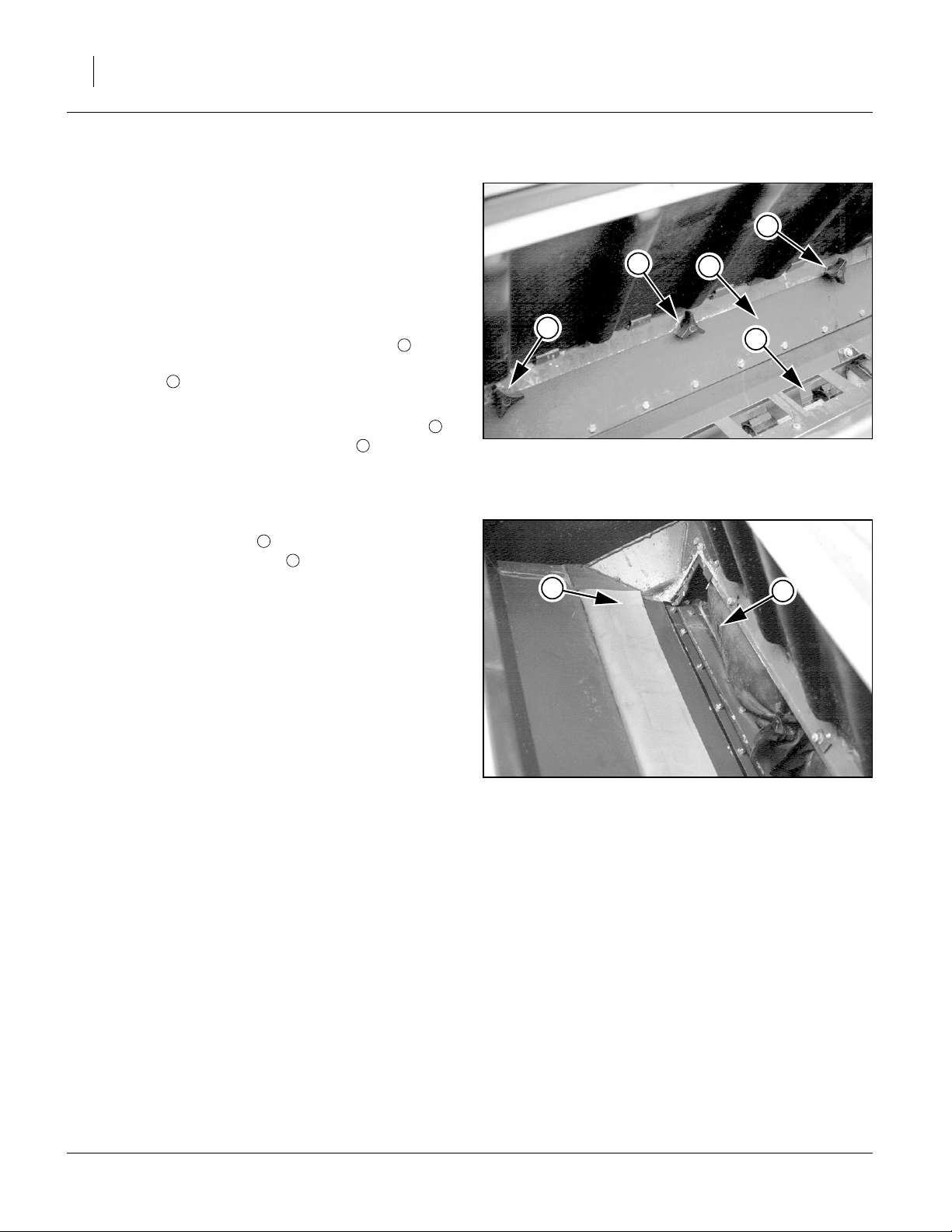
Refer to Figure 25
2. Open the divider door between seed and fertilizer
compartments. To open door, loosen knobs .
1
Loosen knobs until bent clips can be turned away
from door .
2
3. When all bent clips have been turned, lift vinyl dew
shield (shown in Figure 26) and flip the flap door
backward over fertilizer-tray openings .
FigureSpacer:
3
2
Refer to Figure 26
4. With seed/fertilizer flap covering fertilizer openings, lower vinyl dew shield to hold flap over fertil-
2
4
izer meter cup openings and away from divider.
5. To avoid unnecessary wear, remove all three fertilizer transmission chains. See Seed Rate Manual for
details of Fertilizer drive.
FigureSpacer:
1
2
1
Figure 25
Open Seed/Fertilizer Flap
4
1
3
16383
2
FigureSpacer:
Figure 26
16380
Flap Secured
196-522M 03/28/2012
E
Page 31

Great Plains Manufacturing, Inc. Operating Instructions 27
Loading Fertilizer
The 3S-4010HDF models are equipped with a fertilizer
compartment capable of planting seed only, or seeding
and applying fertilizer in the same field pass.
Use only dry, granular fertilizer in the fertilizer box.
Fully loaded with dense fertilizer, the drill can weigh an
additional 4700 lbs (2132kg) or more. Include this weight
when checking tractor capability. Load fertilizer after
transport if possible.
60%
Seed
40%
Fert.
Standard Divider
100%
Seed
Configurations
0%
Fert.
Seeding and applying fertilizer
1. Clean any seed or debris from fertilizer compartment. See “Fertilizer Box Clean-Out” on page 61.
Refer to Figure 27
2. Adjust dividers between seed and fertilizer compartments to desired capacity. See page 28 for details.
The standard fertilizer dividers partition the drill
boxes into: 100% seed or
60 percent seed : 40 percent fertilizer.
The optional offset dividers (page 86) partition the
drill boxes into: 100% seed,
68% seed : 32% fertilizer, or
55% seed : 45% fertilizer.
3. Check that fertilizer clean-out door (page 61) is
closed and all latches are secure.
Refer to Figure 28
4. The fertilizer compartment is accessed via the main
box lid . The main seed box lid handle is also a
latch. Pivot the handle up and open the lid.
5. Flip the spill flap forward to prevent fertilizer from
being loaded into the forward seed compartment.
1
3
68%
Seed
FigureSpacer:
32%
Fert.
Figure 27
Seed Box Divider
Take all prescribed material
safety precautions.
3
4
55%
Seed
Offset Divider
Configurations
45%
Fert.
27003
1
6. Load fertilizer evenly into fertilizer compartment .
4
To reduce wear, remove drive chains for seed boxes not
used.
FigureSpacer:
Figure 28
29083
Main Box Open for Fertilizer
03/28/2012 196-522M
Page 32

28 3S-4010HD and 3S-4010HDF Great Plains Manufacturing, Inc.
Fertilizer Divided Capacities
Capacity Ratio Total Capacity
Seed Fertilizer Seed Fertilizer
None 100% 0% 129.6 bu
0
4567 ltr.
Standard 60% 40% 77.8 bu
2740 ltr.
Offset
to Back
Offset
Forward
68% 32% 88.1 bu
3106 ltr.
55% 45% 71.3 bu
2512 ltr.
51.8 bu
1827 ltr.
41.5 bu
1461 ltr.
58.3 bu
2055 ltr.
Divider Removal
Refer to Figure 29
a. Remove
3
at each end of drill box (2 locations).
b. Remove
5
⁄
in bolts and flange nuts from tabs
16
5
⁄
in bolts (4) and nuts (5) from lid-
16
hinge brackets (3 locations).
c. Loosen but do not remove
clamp the lid assembly angle irons to the plastic
dividers .
9
d. Lift lid assembly out of drill box. Lift dividers out
1 2
4 5
6
1
⁄
in bolts and nuts that
4
8
8 9
7
of drill box. Reinstall standard or offset dividers.
e. Reinstall lid assembly by reversing step d through
step a.
FigureSpacer:
Refer to Figure 30
6. Check that the seed/fertilizer flap at the bottom of the
compartment is closed so seed and fertilizer cannot
pass between compartments.
2
FigureSpacer:
1
8
7
3
9
2
3
1
6
5
4
Figure 29
Box Divider Removal
27050
Flap flips forward to block passage. The flap top
edge is secured to the dividers. Rotate the bent clips
to engage the edge of the flap, and tighten the
knobs.
FigureSpacer:
Figure 30
16383
Seed/Fertilizer Flap Closed
196-522M 03/28/2012
E
Page 33

Great Plains Manufacturing, Inc. Operating Instructions 29
Loading Small Seeds Box
1. If loading prior to transport, and calibration has not
yet been done, set Seed Rate Handle to 0. At 0, no
seed can leak during transport.
2. Take all necessary materials safety precautions if the
seed is treated.
3. The Small Seeds lid is held closed by two external
rubber latches. Pull them up and to the rear to
release the lid.
4. Load seed evenly into compartments .
5. To reduce wear, remove transmission (driver/driven)
chains for main seed boxes.
If you experience excessive seed shifting in your planting, consider installing additional optional partitions
(page 87).
4
4
4
FigureSpacer:
Figure 31
Small Seeds Main Box Open
29084
03/28/2012 196-522M
Page 34

30 3S-4010HD and 3S-4010HDF Great Plains Manufacturing, Inc.
Marker Operation
Single (left side) or dual markers are optional on the 3S4010HD/HDF. See “Flat Fold Markers” on page 84 for
ordering information.
Single Marker Operation
The single marker is extended and retracted directly by
the tractor lever, and has a needle valve adjustment for
speed.
At the start of each pass, Extend the circuit to fully unfold
the marker, and return the lever to neutral. At the end of
each pass, Retract the circuit to fold the marker for the
turn, and return the lever to neutral.
Dual Marker Operation
Dual markers are on circuit which contains an adjustable
automatic sequence valve.
At first use, observe the markers carefully, in case the
side that unfolds is not the intended side.
When the circuit is first Extended, normally the right
marker unfolds, and the left remains in the cradle. When
the circuit is reversed (Retracted), the right marker folds,
and the left remains cradled.
When the circuit is next Extended and Retracted, the
marker on the opposite side unfolds/folds, and the previous marker remains cradled.
At the start of the first pass (assuming right marker
desired), Extend the marker circuit until the right marker
is fully unfolded. Set lever to neutral.
At the end of the pass, Retract the circuit until the right
marker is fully folded.
At the start of the next pass, Extend the circuit to deploy
the opposing marker.
Special Dual-Marker Operations
Passes with same marker side:
• Retract (raise) the marker and make the turn.
• Begin to extend the opposite marker.
• Retract it, and extend the original marker.
Both markers unfolded:
• Fully extend one side.
• Momentarily Retract, then Extend to deploy opposite
side.
196-522M 03/28/2012
E
Page 35

Great Plains Manufacturing, Inc. Operating Instructions 31
Acremeter Operation
The acremeter counts shaft rotations whenever the shaft
is rotating - this is with the drill lowered and in motion or
during crank operation. The meter is programmed to display rotations as acres or hectares, when using all rows,
factory-specified tires and tire inflations.
Note: Unusual conditions and/or non-standard row spac-
ings can cause the acremeter tally to vary from actual acres planted.
Normal Operating Sequence
Note: The acremeter counts rotations during drill calibra-
tion (and if so, can be useful for calibration, although the metermust beon, or moved to, the shaft
being cranked).
1. Record the acremeter reading at the start of planting
(and after calibration). The large “12345.6” format
display is the grand total area planted since meter
installation. If the display is blank, see “Dormant
Display” below.
2. Lower drill and plant. Acremeter counts shaft rotations, calculates acres or hectares, and adds to the
running grand total.
3. During planting (drill lowered and moving forward),
the display blanks (goes dormant), but area tally continues.
4. When raised for turns, obstructions and transport,
the drive wheel stops, and the meter counts no additional (non-planting) rotations.
5. Whenever shaft rotation stops, the LCD display activates after 30 to 60 seconds, and remains visible for
30 to 45 minutes.
6. At the completion of planting, record the final reading
or the grand total. If the display goes dormant before
you can read it, see “Dormant Display”.
7. Subtract the reading at Step 1 from the reading at
Step 6 for the total planted in the present session.
Dormant Display
Refer to Figure 33
To conserve power, the LCD display blanks itself most of
the time. If you need to read the display after it has
“timed out” and gone dormant:
• use the calibration crank to turn the jackshaft once, or
• gently tap or wave a magnet at either of the Great
Plains logo spots on the lower region of the display.
1
Be careful not to scratch the window.
When active the lower left corner displays the revolutions
per acre for which the meter is factory-programmed.
FigureSpacer:
FigureSpacer:
Figure 32
Electronic Acremeter
1
Figure 33
Meter Display (Acres)
27378
29184
03/28/2012 196-522M
Page 36

32 3S-4010HD and 3S-4010HDF Great Plains Manufacturing, Inc.
Clutch/Point Row Operation
Prior to first use, the controller module must be installed
in the tractor cab. See “Install Clutch Switch Module in
Cab” on page 106.
During normal full-swath planting, the console requires
no attention; all switches except Pump are On.
Common tasks requiring switch changes are:
• Calibration
• Point Row planting.
Refer to Figure 34
{
S
m
M
Normal Full Pass
1. Set Master switch ON (up), and Pump OFF.
Set all sections ON (up).
Check that corresponding lamps are on.
2. Height switch automatically energizes clutches when
row units are lowered.
M P
L C R
Point Row
3. Turn desired sections off as non-planting regions are
reached.
4. Turn them back on before commencing next fullwidth pass.
See also see “Clutch Troubleshooting” on page 59.
Calibration
In order to work at a comfortable height, the drill is normally lowered for calibration. If power is on, the clutches
will be engaged, preventing manual operation of the
metering system with the calibration crank.
For calibration of a drill section, set the Master switch
down to center-OFF. This disengages all clutches.
Refer to the Seed Rate Manual for details on calibration.
M
FigureSpacer:
FigureSpacer:
FigureSpacer:
FigureSpacer:
L
RC
F
Figure 34
Cab Switch Box
P
CAL
Switch
or
Function
Indicator
MASTER
M
Switch
MASTER
m
S
L
C
R
P
F
CAL
Lamp
Section
Lamps
LEFT
CENTER
RIGHT
PUMP No function on standard 3S40 drills.
Fuse
CAL
Switch
and Lamp
a. However, the section’s meters may still be coupled to the
drive system, if lock-up bolts are installed in the clutch.
m M
b. If lamp fails to illuminate with set ON, check the
F
fuse . If open, check for damaged cable / failed clutch.
Up: System enabled
Center: System OFF
Down: Height Switch Bypassed ON
On: System enabled
Off: System OFF
On: Clutch energized for that section.
Off: Clutch not energized
Up: section enabled
Down: section disabled
Protects switch box, clutches and
b
battery.
Height switch overridden to ON
28097
a
196-522M 03/28/2012
E
Page 37

Great Plains Manufacturing, Inc. Operating Instructions 33
Electric Clutch Lock-Up
In case of electric clutch failure, an electric clutch can be
mechanically engaged.
Refer to Figure 35 and Figure 36
1. Remove the three M8-1.25x14mm metric bolts
from their storage locations near the clutch. Save the
nuts.
1
2. At the clutch, align the cutouts with the holes .
3. Insert the M8-1.25×14mm metric bolts .
2 3
1
If you observe half the hole obstructed by a metal disc
4
, you are not at a cutout.
If the entire hole is obstructed by a metal disc , you are
4
not at a cutout.
When at a cutout, the bolt will screw in with minimal
resistance until the bolt head reaches the clutch face.
Note: Use only the provided 14mm length bolts. Longer
bolts will damage the clutch. Shorter bolts may not
effect a lock-up. Replacement bolts are Great
Plains part number 802-782C.
Shaft Monitor Operation (Option)
The optional shaft monitor generates an alarm if any one
or more of the three meter shafts on the drill stop turning
for more than 30 seconds.
Refer to Figure 37
To operate shaft monitor, turn system on by activating
on-off switch on monitor head. If seed-cup shafts are
turning, all three indicator lights are illuminated and no
alarm sounds.
If any seed-cup shaft stops for 30 seconds, an alarm
sounds and the indicator for that section flashes on the
monitor, designating the failed shaft.
Note: The 30-second delay is to prevent nuisance alarms
when turning at the end of the field.
Note: If a failure does occur and an alarm sounds, re-
member you have traveled for 30 seconds without
planting with that drill section. If due to wheel lift or
low tire pressure, you may have been planting at
progressively lower populations before that.
1
2
FigureSpacer:
FigureSpacer:
FigureSpacer:
Figure 35
Electric Clutch Lockup
4
3
2
Figure 36
Clutch Plate Nearly at Cutout
2
1
Figure 37
Shaft Monitor Head
1
22906
26168
18943
03/28/2012 196-522M
Page 38

34 3S-4010HD and 3S-4010HDF Great Plains Manufacturing, Inc.
Field Operations
This section presumes that all pre-operation check have
been made on the drill, and the drill is loaded with seed
and (optionally) fertilizer.
Final Field Checklist
❑ Drill unfolded (page 22).
❑ Lock-Out hubs: drive system engaged (page 22).
❑ Seed and fertilizer loaded (page 25).
❑ Set material rates per chart or calibration (page 43).
❑ Check all seed hoses secure.
Planting Sequence
1. Set Master and all section clutch switches ON.
2. Lower drill at initial seeding point.
3. Extend marker for next pass centerline.
4. Pull forward and begin planting.
5. Raise drill for turns (seed flow stops automatically).
6. Retract marker and make turn.
FigureSpacer:
.eps
100%
Figure 38
3S-4010HD Planting
29077
Machine Damage Risk:
Do not make short radius turns with the drill in the ground.
196-522M 03/28/2012
E
Page 39

Great Plains Manufacturing, Inc. Operating Instructions 35
Parking
Following these steps when parking the drill for periods
of less than 36 hours. For longer periods, see Storage,
the next topic.
1. Position the drill on firm, level ground.
Roll-Away Hazard:
Do not unhitch on a slope.
2. Raise the drill.
3. Install lift locks.
4. Fold as necessary for the parking space available.
5. Securely block drill tires to prevent rolling.
6. Dismount jack from storage stob and pin to mount on
side of hitch. If ground is soft, place a board or
masonry block under jack.
FigureSpacer:
FigureSpacer:
FigureSpacer:
Figure 39
Jack in Parking Position
20273
7. Extend jack until tongue weight is off tractor drawbar.
8. Disconnect hydraulic lines, and arrange them so they
cannot contact the ground.
9. Disconnect electrical connections.
Roll-Away Hazard:
Block tires when unhitching. Do not park on slopes.
Tongue weight at jack is not sufficient to anchor drill.
10. Remove hitch pin.
11. Remove safety chain.
Always remove safety chain last.
Storage
Store the drill where children do not play. If possible,
store it inside for longer life.
1. Perform the drill Parking checklist.
2. Lubricate the drill at all points listed under “Lubrica-
tion” on page 75.
3. Check all bolts, pins, fittings and hoses. Tighten,
repair or replace parts as needed.
4. Check all moving parts for wear or damage. Make
notes of any parts needing repair before the next
season.
5. Plug or cap seed delivery tubes to prevent pest entry.
6. Grease exposed cylinder rods to inhibit rust.
7. Use touch-up paint to cover scratches, chips and
worn areas to prevent rust.
End of “Operating Instructions”
03/28/2012 196-522M
Page 40

36 3S-4010HD and 3S-4010HDF Great Plains Manufacturing, Inc.
Adjustments
To get full performance from your drill, you need an
understanding of all component operations, and many
provide adjustments for optimal field results.
The 3S-4010HD and 3S-4010HDF has frame-mounted
or unit-mounted coulters, and double-disk parallel-arm
openers with depth-controlling press wheels. This system provides accurate depth control and seed placement
over uneven terrain.
Each opener is mounted on a floating opener frame, held
parallel to the ground. Opener bodies are staggered for
easy soil flow. A spring provides the down pressure necessary for opener double disks to open a seed furrow.
The spring allows openers to float down into depressions
and up over obstructions. Individual openers can be
adjusted to account for tire tracks.
Even if your planting conditions rarely change, some of
these adjustment items need periodic attention due to
normal wear.
Planting Depth
Setting nominal planting depth, and achieving it consistently, is affected by multiple adjustable drill functions,
from greatest to least effect they are:
• Opener Depth (Press Wheel Height)
• Row Unit Down Pressure,
• Opener Frame Height,
• Frame-Mounted Coulter Force,
• Unit-Mounted Coulter Depth Adjustment,
• Frame Weights (at higher pressures), and;
• Disk Blade Adjustments (as row unit blades wear).
FigureSpacer:
Adjustment Page The Adjustment Affects
Opener Frame Height 37
Frame-Mounted Coulters (FMC) 37
Frame Height - FMC 37 Coulter depth and planting depth
Individual FMC Depth 39 Rows in tracks
Frame-Mounted Coulter Force 40 Unusual conditions
Frame Height w/o Frame-Mounted Coulters 41 Proper row unit operation
Frame Weights 43 Achieving higher no-till down-force settings
Material Rates
Marker Adjustments
Marker Extension Adjustment 18 Pass alignments with no overlap or excessive gap
Marker Disk Adjustment 54 Visibility of mark for next pass
Marker Speed 73 Efficient marker operation at turns
10HD Series Row Unit Adjustments 44
Unit-Mounted Coulter Adjustments 45
Row Unit Down Pressure 47 Consistent seeding depth in tire tracks
Disk Blade Adjustments 51 Consistent seeding depth
Seed Firmer Adjustments 52 Consistent seed placement and coverage
Opener Depth (Press Wheel Height) 53 Seeding depth
Front-to-Back Level 67 Correct seeding depth and furrow coverage
Side-to-Side Level 66 Center vs. wing planting consistency
Height Switch 71 Avoiding wasted and unplanted seed
a. Refer to separate Seed Rate manual (196-522B) for details, normally in manual pak enclosure on drill.
SR
a
Seed population and fertilizer application rates
196-522M 03/28/2012
Page 41

Great Plains Manufacturing, Inc. Adjustments 37
Opener Frame Height
Frame height adjustment methods depend on coulter
configuration:
Refer to Figure 40
1. Frame-Mounted Coulters
frame height information begins on this page.
2. Unit-Mounted Coulters
frame height information begins on page 41.
3. No Coulters
use the same frame height setup as #2, page 41.
FigureSpacer:
1 2 3
Figure 40
Coulter Configurations
27211
Frame-Mounted Coulters
Frame-mounted coulters are an optional alternative to
unit-mounted coulters. Only one type of coulter may be
installed. See page 85 for ordering information.
Frame-mounted coulters are used “in row” and not
“zone”. They are intended to prepare the soil directly
ahead of the seed furrow.
With frame-mounted coulters, the coulter depth controls
opener depth and performance. Set the frame height to
achieve the desired coulter depth.
There are three adjustments for frame-mounted coulters:
Refer to Figure 41
1. Frame height - the running depth of all coulters as a
group. This is set by a hydraulic stop, the next topic.
2. Individual coulter depth - a mechanical adjustment
for a few rows in tire tracks. See page 39.
3. Individual coulter down-force - this is a spring adjustment for rows in tracks, or all rows - in unusually light
or heavy no-till conditions. See page 40.
Frame Height - Frame Mounted Coulters
Refer to Figure 42
In regular or heavy no-till conditions, set
7
the coulter depth to about 1in (2.5cm) deeper than
8
seeding depth.
For example, if
8
the desired seeding depth is 1in (2.5cm), set
7
the coulters to run at 2in (5.1cm) deep.
Setting coulters too deep for conditions can cause
opener plugging and uneven or too-deep seed depth. In
light no-till or conventional till conditions, it may be nec-
essary to set coulter depth to less than 1in (2.5cm)
below seeding depth , or even
ing depth.
In addition to checking depths at setup, be sure to check
actual seeding results while planting.
7
8
1
/
in (6mm) above seed-
4
FigureSpacer:
FigureSpacer:
4
Figure 41
FMC Coulter Adjustment Points
7 8
Figure 42
FMC Coulter to Opener Depth
5
6
20274
27215
27070
03/28/2012 196-522M
Page 42

38 3S-4010HD and 3S-4010HDF Great Plains Manufacturing, Inc.
Crushing Hazard:
Make all down-stop adjustments with circuit in neutral and
drill raised (actuator plunger not in contact with down-stop).
Loosening the down-stop with circuit active and drill lowered
results in rapid lowering of the frame.
Field Result Inconsistency Risk:
Make sure the drill is level and the lift system bled and rephased before adjusting the tool bar height. If the center section does not consistently stop at the set height, or the wings
do not run at the same height as the center, the lift system may
have air or be out of phase (above), or the wings may not be
level. See “Leveling Drill” on page 66.
Refer to Figure 43
Note: The change in coulter height is greater than the
change in down-stop adjustment. Make adjustments in small amounts.
The lift system includes an adjustable stop valve to fix
1
the height of the opener frame when the drill is lowered.
To adjust the stop height
(assuming a desired 1
1
⁄
in / 3.2cm coulter depth):
4
1. Move to smooth level ground with soil as similar as
possible to field conditions.
2. Lower the drill until the coulter blades just touch the
ground. Hold that height by setting the lift circuit to
neutral.
3. Loosen the knob on the stop .
4. Adjust the stop position on the tube until it just
touches the actuator .
2 3
3 4
5
5. Raise and then fully lower the drill.
6. Pull forward 10 feet (3m) and stop.
7. Measure the depth at which the coulters are running.
Measure only in non-tire-track rows where the
coulter springs are not in compression (arm is at full
extension). If the coulters are at the desired depth,
no further adjustment is necessary. Skip to step 11.
8. Raise the drill and set the lift circuit to neutral.
9. Adjust the stop up (to raise depth) or down (to lower
depth). Adjust in small increments. Secure the stop
with the knob on the bolt .
2
10. Check the new setting starting at step 5.
11. Raise and lower several times and confirm that the
drill stops consistently at the new height.
4
1
2
5
3
FigureSpacer:
Figure 43
FigureSpacer:
FigureSpacer:
FigureSpacer:
FigureSpacer:
FigureSpacer:
FigureSpacer:
FigureSpacer:
FigureSpacer:
FigureSpacer:
FigureSpacer:
FigureSpacer:
FMC Opener Depth Stop
Note: It is important that all of the tires remain in contact
with the ground to maintain levelness of machine
from front to rear. Setting the depth control too
deep combined with high opener spring force can
cause the drill to tip forward when planting, which
may cause plugging.
Running with the front tires floating or skimming on
the ground will cause uneven coulter depth and
may cause uneven seed depth.
20274
196-522M 03/28/2012
E
Page 43

Great Plains Manufacturing, Inc. Adjustments 39
Before making any adjustments to individual framemounted coulters, setup the seeding depth on the row
units, and verify that the coulter tool bar height is set for
your conditions.
3
Individual Frame-Mounted Coulter Depth
The running depth of all coulters is adjusted simultaneously by changing the tool bar height. Adjusting the
height of a small number of coulters may be useful for
rows in tire tracks.
Adjust individual coulters as follows.
1. On level ground, lower the drill until coulters just
touch the ground.
2. Raise the drill by the extra amount you need to lower
the rows in tracks.
Refer to Figure 44
3. At each frame-mounted coulter to be adjusted,
slightly loosen all six bolts ( , ) at the mount.
4. Using a rubber mallet, tap the spring bar up or
down until the bottom edge of the coulter disk is at
ground level.
5. Tighten the two clamp bolts until both U-bolts are
firmly against the edge of the spring bar . It is nor-
mal for there to be a small gap between the clamps.
6. Tighten the four U-bolts .
7. Lower the drill to planting height and pull forward 30
feet (10m).
8. Check coulter blade to opener blade (furrow centerline) alignment.
1 2
3
1
3
2
FigureSpacer:
1
Figure 44
Frame-Mounted Coulter Height
2
10300
03/28/2012 196-522M
Page 44

40 3S-4010HD and 3S-4010HDF Great Plains Manufacturing, Inc.
Frame-Mounted Coulter Force
In normal operation at target running depth, the spring is
at full extension or only slightly compressed. It compresses briefly as obstructions and denser soil are
encountered.
Coulter springs are set to 400 lbs (181 kg). In normal
operation at target running depth, the spring is at full
extension. It compresses briefly as obstructions are
encountered.
• In heavy no-till conditions, you may observe the
springs in compression most of the time. This means
that the blades are not reaching the desired coulter
depth. If adequate drill weight is available, you can
increase the spring down-force to compensate.
• In light but rocky conditions, the factory spring setting
may be higher than needed. You can extend blade life
by reducing the force at which the blades ride up over
obstructions.
To adjust the coulter spring:
Refer to Figure 45
1. Raise the drill and install transport locks. See “Rais-
ing” on page 20.
FigureSpacer:
Figure 45
Frame-Mounted Coulter Spring
27139
2. Determine the new spring length desired. See the
1
table at right.
3. Measure the current length of the spring(s) to be
changed. If already shorter than 9
longer than 10
1
⁄
in (26cm), do not further adjust
4
3
⁄
in (24.8cm), or
4
them.
4. Loosen the jam nut .
5. Rotate the adjuster nut until the spring is at the
2
3
new length. Tighten the jam nut.
Note: If all springs are continuously in compression, the
coulters can lift the wing frames off the ground (at
the gauge wheels), resulting in uneven coulter
depth and/or uneven seed depth. If high forces are
required, frame weights are probably required.
Spring Length
1
Force at Blade
10.25 in (26.0 cm) 300 lbs (136 kg)
10.00 in (25.4 cm) 400 lbs (181 kg)
9.75 in (24.8 cm) 525 lbs (238 kg)
FigureSpacer:
Machine Damage Risk:
Do not use spring lengths shorter than 9.75 in (24.8 cm). It
may contribute to premature parts failure which will not be
covered by warranty.
196-522M 03/28/2012
E
Page 45

Great Plains Manufacturing, Inc. Adjustments 41
Frame Height without FrameMounted Coulters
Use these instructions with a drill having no coulters, or
having unit-mounted coulters. Adjustments to individual
unit-mounted coulters themselves are on page 45.
If the drill has frame-mounted coulters, use the height
procedure on page 37.
Refer to Figure 46
Frame height is measured from the bottom of the
opener tool bar (the largest of the tool bars), and is measured with the drill lowered.
The recommended height depends on your field conditions (see table below), and whether unit-mounted
coulters are installed.
Light no-till, or conventional tillage, with unit-mounted coulters
or no coulters
Moderate to challenging no-till
with unit-mounted coulters
1
Conditions
Opener
1
Tool Bar Height
Above 26in
(above 66cm)
At 26in
(66cm)
1
FigureSpacer:
Figure 46
UMC/NC Frame Height
FigureSpacer:
27213
27214
For no-till conditions, a 26in (66cm) height allows the
opener parallel arms to run parallel to the ground giving
the opener the maximum upward or downward flotation.
In loose or conventional planting conditions, a frame
height above 26in (66cm) helps keep the no-till spring
forces from burying the openers.
Note: Setting the frame above the 26in (66cm) limits the
opener downward flotation.
Note: Running with the frame below 26in (66cm) limits
opener upward flotation and could cause opener
damage especially at center of the drill.
Crushing Hazard: Make all down-stop adjustments with circuit in neutral and drill raised (actuator plunger not in contact
with down-stop). Loosening the down-stop with circuit active
and drill lowered results in rapid lowering of the frame.
Field Result Inconsistency Risk:
Make sure the drill is level and the lift system bled and rephased before adjusting the tool bar height. If the center section does not consistently stop at the set height, or the wings
do not run at the same height as the center, the lift system may
have air or be out of phase (above), or the wings may not be
level. See “Leveling Drill” on page 66.
03/28/2012 196-522M
Page 46

42 3S-4010HD and 3S-4010HDF Great Plains Manufacturing, Inc.
Refer to Figure 47
The lift system includes an adjustable stop valve to fix
1
the height of the opener frame when the drill is lowered.
To adjust the stop height:
1. Move to smooth level ground similar to field condi-
tions.
2. Lower the drill and measure the present tool bar
height. If the drill cannot be fully lowered due to row
unit spring settings, temporarily move the cams to a
4
1
2
5
lower setting, or out of notch entirely.
3. Raise the drill.
4. Loosen the knob on the stop .
2 3
3
5. Adjust the stop position on the tube . Adjust up
3 4
(to raise) or down (to lower). Adjust by half the last
difference. Secure the stop with the knob bolt .
2
6. Lower the drill and measure the tool bar height. If the
error is more than about
1
⁄
in (3mm), repeat the
8
adjustment process from step 3.
7. Raise and lower several times and confirm that the
drill stops consistently at the new height.
Note: It is important that all of the tires remain in contact
with the ground to maintain levelness of machine
from front to rear. Setting the depth control too
deep combined with high opener spring force can
cause the drill to tip forward when planting, which
may cause plugging.
Running with the front tires floating or skimming on
the ground will cause uneven coulter depth and
may cause uneven seed depth.
FigureSpacer:
FigureSpacer:
FigureSpacer:
FigureSpacer:
FigureSpacer:
FigureSpacer:
Figure 47
UMC/NC Opener Depth Stop
20274
Height Mis-adjustment Risk:
Make sure the drill is level and the lift system bled and rephased before adjusting the tool bar height.
196-522M 03/28/2012
E
Page 47

Great Plains Manufacturing, Inc. Adjustments 43
Frame Weights
In challenging no-till conditions, a few row-unit downpressure settings (across all rows), and some framemounted coulter settings, may be high enough to lift the
wing gauge wheels off the ground. To avoid inconsistent
results, add weight to the wings.
Up to three pair (six total) optional weight brackets may
be added. See “Dual Weight Kit” on page 84. Each kit
includes two brackets.
Each bracket accepts up to five standard weights, about
500 lbs (227 kg) per wing, or 1000 lbs (454 kg) per kit.
The weights required are common “suitcase” tractor
weights, and are widely available, although not supplied
by Great Plains.
Great Plains recommends loading no more than three
sets of brackets, representing 3000 lbs (1361 kg) total.
Do not add weight to the center section. It is always
heavier than even a fully weighted wing, and never
requires additional weights.
FigureSpacer:
FigureSpacer:
FigureSpacer:
FigureSpacer:
FigureSpacer:
Figure 48
Installing Frame Weights
27068
Note: The table does not include the effect of adding
frame-mounted coulters to the drill.
Available Down Force
Material weight (e.g. seed) is not included in the table, as
its effect dwindles toward zero during planting.
Each Weight set assumed to be fully populated with five
100 pound weights.
Although frame-mounted coulters add 61 lbs (28
kg) to each row, they also rely on the available
weight per row, and can easily require more
weight than they contribute.
Although this reduces the weight available to the
openers, the opener workload is also reduced by
having the furrow prepared by the coulters.
3S4010HD-4810 3S4010HD-6475 3S4010HDF-4810 3S4010HDF-6475
Wing Rows 16 21 16 21
Base Mass Per Row 660 lbs 299 kg 540 lbs245 kg680 lbs308 kg560 lbs254 kg
Markers Add Per Row 59 lbs 27 kg 45 lbs 21 kg 59 lbs 27 kg 45 lbs 21 kg
Small Seeds Adds 13 lbs 6 kg 10 lbs 4 kg 13 lbs 6 kg 10 lbs 4 kg
Each Weight Kit Adds 35 lbs 16 kg 27 lbs 12 kg 35 lbs 16 kg 27 lbs 12 kg
Your Configuration
Material Rate Setting
Details of seed and fertilizer rate setting are found in the
Seed Rate Manual, and rely on data from that manual,
normally located in the manual pak enclosure at front
center of drill).
Rate setting controls are different for each box, but independent for each box. All chart rates, for all boxes, are
approximate. Great Plains strongly recommends calibration of each box to the material to be applied.
Main Box Fertilizer Small Seeds
Coarse Rate Drive Type Sprockets Range Sprockets
Fine Rate Rate Handle Transmission Sprockets
Rate
Handle
Cup Adjustment Door Handle
03/28/2012 196-522M
Page 48

44 3S-4010HD and 3S-4010HDF Great Plains Manufacturing, Inc.
10HD Series Row Unit Adjustments
Refer to Figure 49
(depicting an opener populated with optional accessories)
From front to back, a Great Plains 10HD Series row unit
can include the following capabilities (some optional):
1. Unit-Mounted Coulter (UMC): optional
UMCs are used instead of frame-mounted coulters
and are often preferred where soils are not rocky.
See “Unit-Mounted Coulter Adjustments” on
page 45.
2. Down Pressure Springs and Cam: standard
Each row unit is mounted on the drill via parallel
arms which allow the row unit to independently move
up and down while remaining parallel to the ground.
The cam-adjustable springs provides the force to get
the row unit and attachments into the soil. See “Row
Unit Down Pressure” on page 47.
3. Row Unit Lock-Up: optional
If altering row spacing, unused rows can be raised to
reduce wear. Seed flow is stopped at the boxes. See
“Row Shut Off” on page 49.
4. Disc Blades: standard, 2 per row unit
Double disc blades open a furrow, creating the seed
bed. Spacers adjust the blades for a clean furrow.
See “Disk Blade Adjustments” on page 51.
5. Scraper Separator: standard
No adjustments are necessary.
6. Seed delivery tubes: standard
No adjustments are necessary. There are one, two
or three separate tubes for main seed, Fertilizer and
Small Seeds.
7. Seed firmer: seed flap (not shown) standard:
1
4
FigureSpacer:
FigureSpacer:
FigureSpacer:
FigureSpacer:
FigureSpacer:
Certain Machine Damage:
Do not back up with row units in the ground. To do so will
cause severe damage and row unit plugging.
2
3
5
Figure 49
10HD Series Row Unit
6
8
7
8
27064
Keeton seed firmer (not shown)
Improves seed-soil contact, and provides a stable
arm for a low-rate liquid fertilizer delivery tube. See
“Keeton Seed Firmer Adjustment” on page 52.
Seed-Lok™ firming wheel (shown)
Improves seed-soil contact. See “Seed-Lok™ Seed
Firmer Lock-Up” on page 52.
8. Press wheels: standard (choice of types)
Adjusted by a T-handle, these close the seed trench.
The wheels also support the free end of the row unit,
and provide the primary control over seeding depth.
See “Opener Depth (Press Wheel Height)” on
page 53.
196-522M 03/28/2012
E
Page 49

Great Plains Manufacturing, Inc. Adjustments 45
Unit-Mounted Coulter Adjustments
Unit-mounted coulters are an optional alternative to
frame-mounted coulters. Only one type of coulter may be
installed. See page 87 for ordering information.
Note: Unit-Mount Coulters are not factory-installed.
Check alignment and depth prior to first use.
Note: For frame-mounted coulter adjustments, see
page 37.
Coulter Depth Adjustment
The ideal operating depth for unit-mounted coulters is
1
⁄
in above opener depth. Although they may have origi-
4
nally been set to this depth, coulter (and opener) blades
wear with time, and may need adjusting.
Adjusting the coulter depth is accomplished by re-mounting the coulter blade in one of the six mounting holes
arranged in a staggered pattern in the coulter bracket.
Refer to Figure 50 and Figure 51
Raise drill and install cylinder locks before working on
coulters. Row unit may be fully lowered or locked up. Do
not attempt to move blade when the current or new position causes it to contact the ground during the adjustment. Be careful around the front end of row units.
Coulter blades may be sharp.
To adjust coulter depth:
1. Determine the present opener and coulter depths.
FigureSpacer:
Figure 50
10HD Series Unit-Mounted Coulter
7
29124
2. Note which bracket hole the coulter is presently
using.
3. Determine which new hole will position the coulter
closer to the
4. Remove the
1
⁄
in-above depth. See the table below.
4
5
⁄
-11 x 4in bolt, lock washer and nut (
8
in Figure 50).
5. Move the blade to the new position. Insert the bolt,
and tighten on the lock washer and nut.
Hole
No.
2
3
5
1
4
6
Depth of (new) coulter blade relative
to (new) opener blades
1in (25mm) above
5
⁄
in (16mm) above
8
1
⁄
in (6mm) above
4
0 (factory standard hole)
3
⁄
in (10mm) below
8
3
⁄
in (19mm) below
4
If a worn coulter cannot be adjusted to satisfactory operating depth, replace the coulter blade.
2
3
7
5
1
4
6
FigureSpacer:
Figure 51
Coulter Blade Mounting Holes
29125
03/28/2012 196-522M
Page 50

46 3S-4010HD and 3S-4010HDF Great Plains Manufacturing, Inc.
Coulter Row Alignment
Refer to Figure 52
For both frame- and unit-mounted coulters, the ideal
alignment is for the blade to prepare a furrow directly
ahead of the opener discs.
As a check on coarse alignment, sight along the coulter
blade centerline , the gap between the opener blades
2 3
, and the centerline between the press wheels . If
they are clearly out of alignment, either the coulter or the
press wheels (or both) may be in need of adjustment.
The exacting test of correct alignment is field results.
Operate the drill on some test ground (no seed required),
and verify that the opener blades are in the groove
opened by the coulter.
Adjust UMC Alignment
To adjust unit-mounted coulter alignment, loosen the four
4
bolts that attach its bracket to the row unit. The holes
on the row unit are slotted, side-to-side, and allow the
coulter bracket sideways and rotational adjustment.
Keep the coulter blade vertical while adjusting.
If the blade cannot be brought into alignment, check that
the blade spindle itself is using the same hole location on
each side of the bracket.
Adjust FMC Alignment
To adjust frame-mounted coulters, loosen the same bolts
used to make vertical adjustments. See page 37.
1
4
3
2
1
FigureSpacer:
Figure 52
10HD Unit-Mount Coulter
29219
196-522M 03/28/2012
E
Page 51

Great Plains Manufacturing, Inc. Adjustments 47
Row Unit Down Pressure
Refer to Figure 53
The ideal amount of down-force causes the press wheels
to compress any loose surface soil, but not press a
trench into subsoil.
To assess down-force, operate the drill for a short distance on typical ground (with or without seeding), and
stop. Leave the drill lowered (row units in ground).
At several row units, inspect the furrow created by the
opener discs and closed by the press wheels.
Note: Be sure to inspect rows both in and out of tire
tracks.
FigureSpacer:
Refer to Figure 54
1. If the press wheels are leaving no tracks, or light
tracks, increase down-force.
2. If the wheels are compressing trash and loose soil,
and leaving clear tracks right at the top of the subsoil, down-force is probably correct and needs no
adjustment.
3. If the wheels are creating a trench into the subsoil,
down-force is too high and needs to be reduced.
Adjusting Row Unit Down Force
The springs allow the row units to float down into depressions and up over obstructions.
With Frame-Mounted Coulters
With frame-mounted coulters, the seed trench is primarily opened by the coulters. Row unit springs provide only
additional assistance needed to make a furrow “V”
shaped and ensure furrow closure by the press wheels.
Often, the rows may be run at the minimum spring setting, other than in tire tracks, which commonly need
some adjustment.
If trench depth is not being achieved across all rows,
adjust the force and/or depth of the coulters before making row unit spring adjustments.
With Unit-Mounted Coulters (or no coulters)
Without frame-mounted coulters, the row unit springs
provide the primary down force for cutting through residue and opening the seed trench.
If you cannot achieve enough down force, adding a
weight kit may help. See “Frame Weights” on page 43.
FigureSpacer:
Checking Furrow
Light or no press wheel
tracks
Press wheel(s) compress
loose soil only
Press wheel(s)
making deep tracks
FigureSpacer:
Assessing Down-force
Inspect Furrow Here
Figure 53
Insufficient down-force
Increase down-force
1
Ideal
No adjustment required
2
Down-force too high
Reduce down-force
3
Figure 54
{
27064
03/28/2012 196-522M
Page 52

48 3S-4010HD and 3S-4010HDF Great Plains Manufacturing, Inc.
Adjusting 10HD-Series Down-Force
Refer to Figure 55
An adjuster cam sets row unit spring down pressure individually for each row unit. This is useful for penetrating
hard soil and planting in tire tracks.
The notes in the left table below are based on a drill without coulters. About 120 lbs (54 kg) of the down-force is
the weight of the row unit itself. The additional force is
due to the springs lifting against the mass of the wing.
1
With factory-installed frame-mounted coulters, only 2
springs are installed, to provide finer down-force control
at the opener disks (right table).
With frame-mounted coulters installed, they also lift
against wing mass, effectively reducing the maximum
cam settings without weights, but also reducing the workload of the openers, so down force settings may be
lower. Test, without seeding, in your conditions, to determine optimal down-force settings, and whether additional
weight is required.
Refer to Figure 55
6
To adjust down pressure, use an adjustable or open-end
1
1
⁄
in (29mm) wrench.
8
1. Raise the drill. Although this adjustment can be
made with the drill lowered, the springs will be in tension, and will require more effort. The extra force
required may also damage tools.
2. Put tractor in Park and shut it off.
3. Position wrench on hex nut weldment.
4. Pull upper spring link back.
FigureSpacer:
Figure 55
27065
Row Unit Minimum (one)
FigureSpacer:
FigureSpacer:
FigureSpacer:
FigureSpacer:
Note: Do not set all rows so high that planting becomes
and Maximum (six)
uneven or gauge wheels skid or lift off ground.
5. Move the adjustment cam to the new setting on the
spring adjust bar.
Cam Down-Force Settings
Cam
Notch
zero zero
(out of notch)
Maintenance Only
Standard (4) Springs Springs Reduced for FMC
Pounds 7.5in 10in Pounds 7.5in 10in
Cam
Notch
one 250 lbs (113 kg) one 185 lbs (84 kg)
two 275 lbs (125 kg) two 198 lbs (90 kg)
three 310 lbs (141 kg) three 215 lbs (98 kg)
four 370 lbs (168 kg) Note 1 four 245 lbs (111 kg) Note 2
five 430 lbs (195 kg) Note 1 Note 1 five 275 lbs (125 kg) Note 2 Note 2
six 490 lbs (222 kg) Note 1 Note 1 six 305 lbs (138 kg) Note 2 Note 2
(tip) Do Not Use (tip) Do Not Use
Note 1: Setting to this down-force on all rows of a drill may require Markers and/or Weight sets
Note 2: Setting this down-force on all rows require Markers and/or Weight sets due to frame-mounted coulters
196-522M 03/28/2012
E
Page 53

Great Plains Manufacturing, Inc. Adjustments 49
Row Shut Off
Using optional plugs, seed flow can be shut off for individual main box or Small Seeds box rows, but not for Fertilizer rows. Using optional pins, unused rows can be
raised and locked up to reduce wear.
Main Seed Row Shutoff
If alternate row spacings are desired, the unused rows
can be shut off with optional plugs (page 85).
1. Clean-out seed. The seed box must be empty prior
to inserting plugs. See “Main Seed Box Clean-Out”
on page 61.
2. Insert one plug at each row to shut off. Verify the
seed hose path before inserting the plug, as some
hoses do not make a strictly vertical drop to their row
units.
3. Review seed rate settings prior to planting. Perform
calibration calculations with the actual active row
count.
4. Review marker extension setting. Drill centerline may
have shifted, and correct extension values are likely
to have changed and may differ on each side (and
differ for opposing vs. concentric passes).
Small Seeds Row Shut-Off
If alternate row spacing is required for small seeds,
optional plugs (page 86) are available to block flow inside
the seed box tray.
1. Clean-out seed. The seed box must be empty prior
to inserting plugs. See “Small Seeds Box Clean-
Out” on page 62.
2. Before installing plugs, inspect the seed boxes for
existing factory-installed plugs. These are blocking
extra unused seed ports. You may want to identify
these plugs with an indelible marker.
3. Insert one plug at each row to shut off. Verify the
seed hose path before inserting the plug, as some
hoses do not make a strictly vertical drop to their row
units.
4. Review seed rate settings prior to planting. Perform
calibration calculations with the actual active row
count.
5. Review marker extension setting. Drill centerline may
have shifted, and correct extension values are likely
to have changed and may differ on each side (and
differ for opposing vs. concentric passes).
When removing plugs to restore rows to operation, be
sure to not disturb a factory-installed plug.
FigureSpacer:
FigureSpacer:
Figure 56
Seed Cup Plug
Figure 57
Small Seeds Tube Plug
26279
27407
03/28/2012 196-522M
Page 54

50 3S-4010HD and 3S-4010HDF Great Plains Manufacturing, Inc.
d
d
Row Unit Lock-Up
Wear of ground-contact components of unused rows can
be minimized by locking up a row unit. Lock-up requires
use of one optional pin (part number is 805-033C) for
each row locked up.
1
Refer to Figure 58 (depicting similar 10HDP row)
When not in use, lock-up pins are normally stored in a
1
hole at the top of the opener mount.
1. Raise the drill. Although this adjustment can be
made with the drill lowered, the row unit springs
would be in tension, and require more effort. The
extra force may also damage tools.
2. Set the down pressure springs to minimum force, per
the instructions on page 48.
Refer to Figure 59 (depicting similar 10HDP row)
3. Raise the row unit high enough that the hole for
the pin is above the lower parallel arm :
2
3
FigureSpacer:
FigureSpacer:
FigureSpacer:
FigureSpacer:
Figure 58
Lock-Up Pin Storage
22517
a. use a hoist at the rear of the opener,
b. use a jack under the opener extension, or;
c. place a block under the row, and lower drill.
Loss of Control and Sharp Object Hazard:
Do not lift a row unit by hand. The weight of the unit, plus the
spring force (even at minimum) is too great (plus, a free han
is needed for pinning). Even with multiple people lifting, han
Equipment Damage Risk:
Do not pin the row unit while it is in the lowered position. If
lifting is unsafe - there are numerous sharp edges, and the row
unit will snap down violently if a grip is lost.
the pin is inserted below the parallel arm, row unit damage
will occur when planting begins.
4. Remove the pin from the storage hole and insert and
secure it in the lock-up hole.
5. Lower row unit. Parallel arm rests on lock-up pin.
6. Repeat for all rows needing lock-up.
2
3
FigureSpacer:
Figure 59
Row Lock-Up
196-522M 03/28/2012
E
21981
Page 55

Great Plains Manufacturing, Inc. Adjustments 51
Disk Blade Adjustments
Opener disc angle and stagger is not adjustable, but
disc-to-disc spacing is, and may need attention as discs
experience normal wear. Spacers will need to be reset
when blades are replaced.
Refer to Figure 60
The ideal spacing causes the blades to be in contact for
about one inch. If you insert two pieces of paper between
the blades, the gap between them should be 0 to 1.75in
(0-4.4cm).
If the contact region is significantly larger or smaller (or
there is no contact at all), it needs to be adjusted by moving one or more spacer washers. If the contact region
varies with blade rotation, one or both blades is likely
bent and in need of replacement.
FigureSpacer:
Adjusting Disc Contact
FigureSpacer:
Figure 60
Checking Disk Contact
26447
Sharp Object Hazard:
Row unit disk blades may be sharp. Use caution when making
adjustments in this area.
Refer to Figure 61
1. Raise the drill and install the transport locks.
2. Remove the bolt retaining the opener disc on one
side. Carefully remove the disc, noting how many
spacers are outside the disk and inside the disk. Do
not lose the hub components and spacer washers.
3. To reduce the spacing between the discs (the normal
case), move one spacer washer from the inside to
the outside of the disc.
4. Re-assemble and check disc contact.
FigureSpacer:
FigureSpacer:
2
1
3
3
3
3
Figure 61
Adjusting Disk Spacers
26385
03/28/2012 196-522M
Page 56

52 3S-4010HD and 3S-4010HDF Great Plains Manufacturing, Inc.
Seed Firmer Adjustments
10HD Series row units include a seed flap, or one of two
optional seed firmers.
The seed flap requires no adjustment, but may need to
be replaced if worn, and may need to be shortened if an
optional seed firmer is added after initial delivery.
Sharp Object Hazard:
Row unit disk blades may be sharp. Use caution when making
adjustments in this area. To adjust the Keeton Seed Firmer,
lower the drill until the disks of the row units are resting on the
ground.
Keeton Seed Firmer Adjustment
The optional Keeton Seed Firmer is an engineered polymer shape that slides down the seed trench. It traps
seeds as they exit the seed tube and firms them into the
bottom of the “V”.
Refer to Figure 62
The Firmer is provided with a preset tension which is recommended for using the first year. The tension screw
1
can be tightened in subsequent years according to your
needs. Firmers should provide just enough tension to
push seeds to the bottom of the trench.
Seed-Lok™ Seed Firmer Lock-Up
Optional Seed-Lok firming wheels provide additional
seed-to-soil contact. The wheels are spring loaded and
do not require adjusting. In some wet and sticky conditions the wheels may accumulate soil. To avoid problems
associated with this, you can lock-up the firmers.
Refer to Figure 63 (which depicts a row unit with the opener
blades removed for clarity)
To lock up Seed-Lock wheels:
FigureSpacer:
Figure 62
Keeton Seed Firmer
2
1
26390
1. Pull firming-wheel arm up as high as possible.
2. Flip the lock tip to hold the arm up.
2
1
FigureSpacer:
Figure 63
1
27072
Seed-Lok™ Lock-Up
FigureSpacer:
196-522M 03/28/2012
E
Page 57

Great Plains Manufacturing, Inc. Adjustments 53
Press Wheel Adjustments
Opener Depth (Press Wheel Height)
Seeding depth on 3S-4010HD and 3S-4010HDF is set
by frame-mounted coulter depth (if installed) and row unit
depth. Whether frame-mounted coulters are installed or
not, set frame height (page 37 or page 41) before making row unit depth adjustments.
10HD Series press wheel height is a stop adjustment
and not a spring adjustment. It establishes a fixed relationship between opener depth and the closed-furrow
surface at the press wheel
Refer to Figure 64
Set opener seeding depth by adjusting press-wheel
height . To adjust, first raise openers slightly, then lift
and slide T handles on top of openers. Initially adjust
all press wheels to the same height. Individual rows running in tire tracks may need to be set deeper
• For more shallow seeding, slide T handles forward
• For deeper seeding, slide T handles backward
If press wheels are lifting off ground, check front-to-back
level, and increase row unit spring down force.
If press wheels are digging into ground, reduce spring
down force at the row units.
1
toward drill.
away from drill.
2
a
.
F
B
FigureSpacer:
Figure 64
27124
Initial Opener Depth
Press Wheel Spacing
Double V Press Wheel Adjustment
1
4
Refer to Figure 65
The double-V closing wheels can be moved inward
1
and outward to alter how they close the seed trench and
press soil over the seed.
To move the wheels in toward the center of the trench,
remove one of the
1
⁄
in (6.4mm) spacer bushings next
4
2
to the press wheel arm and position it under the head of
the hex head cap screw .
On wider row spacings the closing wheels can be moved
outward by relocating the spacers to the inside, next to
the press wheel arm .
3
2
3
4
FigureSpacer:
Figure 65
Double-V Press Wheels
FigureSpacer:
a. If frame-mounted coulters are installed, adjust them for tire tracks before adjust T-handles. The coulter depth adjustment may be all
that’s required to compensate for tracks.
23428
03/28/2012 196-522M
Page 58

54 3S-4010HD and 3S-4010HDF Great Plains Manufacturing, Inc.
Marker Adjustments
This section covers marker items that may need adjustment for current conditions, and assumes that the markers are installed, set to the correct initial extension and in
proper working order. See also:
•“Marker Setup” on page 18
•“Marker Maintenance” on page 73
Marker Disk Adjustment
W
1
N
T
T
2
Sharp Object Hazard:
Marker disks may be sharp. Use caution when making adjustments in this area.
Adjusting Mark Width
Refer to Figure 66
T
is the direction of travel.
To change angle of cut, and the width of the mark, loosen
1
⁄
-inch bolts holding the disk assembly.
2
For a wider mark , increase the angle of the marker
with respect to the tube . For a narrower mark ,
2
W
1
N
reduce the angle.
FigureSpacer:
Figure 66
Marker Disk Angle
T
11757
Tighten bolts .
2
Direction of Cut
Refer to Figure 67
To have the marker throw dirt out, invert the disk on the
spindle, and invert the disk assembly.
FigureSpacer:
Marker Chain Length
Refer to Figure 68
With marker unfolded, adjust chain to a length
1
of 63in (160cm)
Slowly fold marker while observing disk. If marker disk
slides across the ground more than a foot (0.3m) before
chain and linkage lifts it up, the chain is too long.
Remove bolt and shorten chain one or two links.
Check adjustment by repeating folding process.
If chain is too short when marker is unfolded, it will prevent the marker blade from dropping into field depressions, causing skips in the mark line. Correct this
condition by lengthening chain one or two links.
End of “Adjustments”
2
FigureSpacer:
FigureSpacer:
Figure 67
11248
Marker Disk Inverted
2
1
Figure 68
21888
Marker Chain Length
196-522M 03/28/2012
E
Page 59

Great Plains Manufacturing, Inc. Troubleshooting 55
Troubleshooting
General Troubleshooting
Problem Cause Solution
Planting too much Excessive overlap Adjust marker, page 18.
Incorrect Drive Type (Main Box) Check sprocket set up (Seed Rate Manual).
Seed meter incorrectly set Check handle against chart (Seed Rate Man-
ual).
Seed cup door too open (Main Box) Narrow door opening for seed size (Seed
Rate Manual).
Seed size and/or density varies from
charts
Incorrect tire size or pressure. Check tires per page 89. Adjust air pressure.
Meter flutes damaged Inspect and service as necessary.
Actual field size is different Verify field size.
Planting too little Excessive field speed Slow down.
Pass gaps. Adjust marker, page 18.
Incorrect Drive Type (Main Box) Check sprocket set up (Seed Rate Manual).
Seed meter incorrectly set Check handle against chart (Seed Rate Man-
Seed cup door too narrow (Main Box) Widen door opening for seed size (Seed Rate
Seed size and/or density varies from
charts
Plugged opener seed tube Lift drill, inspect and clear tube.
Contaminated seed or treatment buildup in meters
Skipping chain or severely worn
sprockets
Excessive seed cracking Excessive field speed Slow down.
Seed cup door too narrow (Main Box) Open as needed for seed size (see Seed
Unclean seed. Use clean seed.
Damaged, old or dry seed Use clean, new seed.
Calibrate for your seed (Seed Rate Manual).
For incorrect size, use calibration to compensate until correct tires are installed.
ual).
Manual).
Calibrate for your seed (Seed Rate Manual).
Use new clean seed. Clean out meters.
Adjust chain slack (page 63). Replace worn
sprockets.
Rate Manual).
03/28/2012 196-522M
Page 60

56 3S-4010HD and 3S-4010HDF Great Plains Manufacturing, Inc.
Problem Cause Solution
No Seed Flow Rockshaft hubs locked out Engage hubs (page 22).
Seed cup door setting is smaller than
seed size (large seed, Main Box)
Height switch mis-adjusted or malfunctioning
Clutch failure Lower drill to engage height switch and
Chain break Check all stages of chains from ground drive
Seed run-out Check seed box.
Obstruction in meter. Clean-out meter.
Seed plugs installed Remove any unintended seed tube plugs.
Uneven seed spacing Seed-Lok plugging Lock up Seed-Lok, page 52.
Drive Type too low Use higher Drive Type and lower handle rate.
Damaged or missing seed flap Replace seed flap.
Openers not penetrating low spots Check/adjust frame height, coulter settings,
Opener disks not turning. See “Opener disks not turning freely” in this
Drill boxes do not empty evenly
Openers drill too deep (bulldozing)
Drive Type (Main Box) or rate adjusters
not the same on all sections
Opener seed tube plugged. Raise drill and clean out seed tube with wire.
Chains broken or skipping. Check chain condition and slack on all sec-
Concentric passes - if planting in turns,
inside boxes plant less than outside.
On 7.5in/19cm spacing, center box
empties first, as it has one more row
than wing boxes.
Rough or steep traverse field conditions moves seed in boxes.
Too much opener spring force. Reduce opener down force to match condi-
Frame height too low Check and adjust (page 17).
Incorrect press wheel adjustment Check and adjust (page 53); however, do not
Open doors for even flow with minimal cracking. See Seed Rate Manual.
Check that clutches cycle with height switch
operation. Readjust switch engagement point
(page 71).
clutches. Shaft should be impossible to move
at calibration crank if clutch is engaged.
wheels to meter boxes.
row down-force and weight available per row.
Troubleshooting chart.
Check and correct.
tions.
Reverse pass direction periodically, add more
seed to outside boxes, or use opposing
passes.
Add extra seed to center box.
Add extra seed. For Small Seeds, install
dividers.
tions (page 47).
use press wheels to compensate for incorrect
down force.
196-522M 03/28/2012
E
Page 61

Great Plains Manufacturing, Inc. Troubleshooting 57
Problem Cause Solution
Uneven seed depth Excessive field speed Slow down.
Coulter depth adjustment Verify coulter-to-opener relationship.
Opener disks not turning freely
Meter flutes locked up or
shaft twisted
Press wheels not compacting the soil as
desired
Coulter down-force insufficient coulters not achieving depth
Insufficient opener down force for conditions
Conditions too wet Wait for dryer weather.
Seed-Lok plugging Lock up Seed-Lok, page 52.
Damaged or missing seed flap Replace seed flap.
Damaged opener seed tube Check for damage at tip of seed tube.
Partially plugged opener seed tube Lift up drill, expose bottom of seed tube and
Incorrect choice of coulter Change coulter blade.
Skimming (gauge wheels skipping, or
off ground entirely)
Opener plugged with dirt Clean opener. Adjust scraper.
Planting conditions too wet Wait until drier weather.
Seed-Lok is plugging opener Lock up Seed-Lok, page 52.
Too much blade-to-blade contact Adjust disk contact. See page 51.
Failed disk bearings Replace disk bearings.
Bent or twisted opener frame Replace opener frame.
Obstruction(s) in meter cups Clean out cups.
Treatment build-up in cups Disassemble and clean cups/flutes.
Too wet or cloddy Wait until drier weather or rework ground.
Coulter set too shallow Adjust coulter depth. See page 37 or
Incorrect press wheel depth setting Adjust T-handle. See page 53.
Opener spring pressure too low or too
high
Add weight or, if weight is sufficient, increase
coulter spring settings.
Adjust row unit cam, page 48.
clean out.
Reduce coulter and/or row unit down forces,
or add weights.
page 45.
Reduce opener spring pressure.
03/28/2012 196-522M
Page 62

58 3S-4010HD and 3S-4010HDF Great Plains Manufacturing, Inc.
Problem Cause Solution
Press wheel or openers plugging
Marker Malfunction Air or oil leaks in hose fittings or con-
Marker disk does not mark
Drill does not fold or unfold fully
Drill hunts in transport Worn skid blocks Replace blocks or add shims
Planting conditions too wet Wait until drier weather.
Coulters not set deep enough to cut
residue
Coulters set too deep, bring up excess
dirt and moisture
Drill not set to run level from front to
rear, carrying enough weight on gauge
wheels to prevent “nosing over”, or set
too low on rear caster eyebolts allowing
it to run “nose high”
Opener set too deep Readjust, page 53.
Opener spring force too high Readjust, page 47.
Backed up with drill in the ground Clean out and check for damage.
Failed disk bearings Replace disk bearings.
Disk blades worn Adjust or replace disk blades, page 51.
Scraper worn or damaged Replace scraper blade.
nections
Market circuit not selected Check Fold/Marker selector valve (if installed
Low tractor hydraulic oil level Check tractor hydraulic oil level.
Loose or missing bolts or fasteners Check all bolts and fasteners.
Needle valve plugged (single marker) Open needle valve, cycle markers slowly and
Needle valve(s) in sequence valve
plugged
Marker folding linkage does not have
enough slack to allow marker disk to
drop into field depressions
Disk angle or orientation not optimal Angle marker disk blade, or reverse blade to
Air in lines Bleed fold system (page 64).
Cylinders out of phase Re-phase cylinder (page 64).
Cylinder mounts misaligned Check spacers, page 65.
Fluid run-out Check tractor fluid level.
Uneven or soft ground Pull ahead slightly while folding is completed.
Locks not engaged Check lock operation
Caster detent pressure and caster
pressure plate not set properly
Check coulter adjustment.
Check coulter adjustment.
Check “Leveling Drill” on page 66.
Check all hose fittings and connections for air
or oil leaks.
on drill)
reset needle valve, refer to page 73.
Open needle valves, cycle markers slowly
and reset needle valves, refer to page 73.
Check chain length, page 54.
pull or throw dirt.
Adjust casters (page 72).
196-522M 03/28/2012
E
Page 63

Great Plains Manufacturing, Inc. Troubleshooting 59
Problem Cause Solution
Acremeter Inaccurate
Chain fouling Clip reversed at link Invert direction of clip (page 63).
Incorrect tire size or pressure. Check against page 89. Meter is factory-pro-
grammed for the original tire size, pressure,
as well as sprockets to jackshaft.
Pass misalignment (overlaps or gaps) drill is actually covering more or less
acreage than is present.
Soil conditions Loose soil or excess tire slippage causes
Acremeter revs/area incorrect Check displayed revs/ac or revs/ha against
Actual field size is different, and
acremeter is correct
Check/adjust markers.
variations in registered acres (and variations
in seeding rates).
page 83.
Check field size.
Clutch Troubleshooting
Problem Cause Solution
no seed metering, all rows fuse blown Check fuse. Correct underlying fault before
replacing fuse.
height switch not tripping Check adjustment of height switch (page 71).
height switch failed Replace switch. Use CAL mode to operate
until switch is replaced.
no metering, one section clutch failure Lock-up clutch until repaired or replaced
(page 33).
section control switch Off or failed Turn switch On. Replace if failed.
wing transfer shaft disengaged Realign transfer shaft (page 69).
seed rate low or uneven lubricant in clutch Disassemble and de-grease clutches.
meters always on CAL mode on Move Master switch handle from CAL to ON.
height switch always on Check adjustment of height switch (page 71).
End of “Troubleshooting”
03/28/2012 196-522M
Page 64

60 3S-4010HD and 3S-4010HDF Great Plains Manufacturing, Inc.
Maintenance and Lubrication
Proper servicing and maintenance is the key to long drill
life. With careful and systematic inspection, you can
avoid costly maintenance, downtime and repair.
Always turn off and remove the tractor key before making
any adjustments or performing any maintenance.
OFF
Crushing and Overhead Hazards:
You may be severely injured or killed by being crushed under a
falling drill. Always have frame sufficiently blocked up when
working on, and particularly under drill.
High Pressure Fluid Hazard:
Escaping fluid under pressure can have sufficient pressure to
penetrate the skin. Check all hydraulic lines and fittings before
applying pressure. Fluid escaping from a very small hole can
be almost invisible. Use paper or cardboard, not body parts,
and wear heavy gloves to check for suspected leaks. If an accident occurs, seek immediate medical attention from a physician familiar with this type of injury.
After using drill for several hours, check all bolts to be
sure they are tight.
1. Securely block drill before working on it.
2. Lubricate areas listed under “Lubrication” on page
75.
3. Clean any fittings that do not take grease.
4. Inflate tires as specified on “Tire Inflation Chart”on
page 89.
5. Inspect hydraulic hoses for cuts, cracks and aging.
Check fittings for evidence of leaks.
6. Keep disk scrapers properly adjusted.
7. Replace any worn, damaged or illegible safety
decals. Order new decals from your Great Plains
dealer. See “Safety Reflectors and Decals” on
page 6.
196-522M 03/28/2012
Page 65

Great Plains Manufacturing, Inc. Maintenance and Lubrication 61
Materials Clean-Out
Main Seed Box Clean-Out
Refer to Figure 69, which depicts the seed cup door handle
in a normal operating position.
1. Set the Seed Rate Handle to zero (0) for the section
of the drill to be cleaned out. This moves the seed
cup sprockets out of the seed path.
2. Position a tarp or bucket under each row or set of
rows to be cleaned out.
1
3. At the seed cup for that row, pull the door handle
1
out of the operating detent range, and swing it down
to position .
2
4. Open the main seed box and use a small brush to
sweep seed toward seed cups set to clean-out. If
seed does not flow freely, inspect seed cup, hose
and seed tubes for obstructions.
5. Wash out the seed box with high pressure water.
Seed meter drive shaft operation is unnecessary for
clean-out. With the Seed Rate set to zero, nothing moves
inside the seed cups; however, an inspection of the flutes
for excess wear and damage does require shaft rotation.
Set the Seed Rate Handles to 100. With openers raised,
the jackshafts can be slowly turned by one person with a
7
⁄
in (22mm) open-end wrench, while another inspects
8
the flutes from the open seed boxes.
Fertilizer Box Clean-Out
After applying fertilizer, clean drill boxes as soon as possible. Fertilizers often contain chemicals corrosive to
metal.
Refer to Figure 70
With a small scoop or can, remove as much fertilizer as
possible from drill boxes.
Clean-out releases material across the entire length of a
section box. Have collection equipment prepared.
Release all clean-out latches on a drill section, and open
clean-out door. Leave door open until after washout.
FigureSpacer:
FigureSpacer:
1
Figure 69
Seed Cup Clean-Out
Figure 70
A Fertilizer Clean-Out Latch
2
26211
16376
Refer to Figure 71
Wash inside of drill boxes with water under high pressure. To aid clean out, lift vinyl cover shield and spray
into fertilizer trays (with clean-out door open).
Let drill boxes dry before closing clean-out doors.
FigureSpacer:
Figure 71
16382
Dew Shield at Openings
03/28/2012 196-522M
Page 66

62 3S-4010HD and 3S-4010HDF Great Plains Manufacturing, Inc.
Small Seeds Box Clean-Out
1. Open lid of each box and scoop out as much seed as
possible.
2. To recover remaining seed, place a collection tarp
under the small seeds tubes at the openers.
3. Raise drill.
4. Set seed rate handles to 100.
5. Rotate clutch shaft until no seed flows.
6. If a vacuum cleaner is available, remove any residual
seed from top of meters.
Seed Flap Replacement (s/n B1010B-)
Refer to Figure 72
To replace a seed flap use a needle nose pliers or
similar tool and squeeze the tabs together. Pull plastic
seed flap down out of metal bracket .
If replacing with 817-349C:
Push new seed flap up through metal bracket until
tabs on seed flap snap in place.
If replacing with 816-302C:
See seed flap replacement instructions below.
1 3
2
1
2
1 3
2
2
3
Seed Flap Replacement (s/n B1011B+)
Refer to Figure 73
To replace an 816-302C seed flap use a needle nose
pliers or similar tool to grasp “T” top of flap. Pull upward
to pull flap up out of metal bracket .
Push new seed flap down through metal bracket
until flap snaps into place with “T” top resting on top of
bracket.
4 5
4
5
FigureSpacer:
Null4:
1
Figure 72
817-349C Seed Tube Flap
19398
5
4
Figure 73
816-302C Seed Tube Flap
31047
196-522M 03/28/2012
E
Page 67

Great Plains Manufacturing, Inc. Maintenance and Lubrication 63
Chain Maintenance
Inspect and lubricate chains regularly. The slack of new
chains tends to increase during the first few hours of
operation due to seating.
Chain Slack
Check slack within the first 8 hours of operation and
tighten idlers as necessary.
Refer to Figure 74, which, for clarity, greatly exaggerates
slack, and omits the idlers.
1. Measure the span for allowable slack:
Locate the longest span of each chain (usually the
span which does not run through the idlers).
2. Determine the ideal slack:
Long chains (over 36in/91cm):
Vertical short chains:
Horizontal short chains:
3. Measure the current slack :
Acting at a right angle to the chain span at the center
of the span, deflect the chain in both directions. The
slack is the distance of the movement.
4. Adjust the idlers for ideal slack.
Whenever mounting a chain, make sure the clip at the
removable link is oriented to minimize snags.
Refer to Figure 75 (arrow shows chain direction)
Install clip with open end facing away from direction of
chain travel (shown by gray or striped arrows in chain
routing diagrams).
1
1
⁄
1
⁄
in per foot (2.1cm/m)
4
1
⁄
2
4
in per foot (4.2cm/m).
2
in per foot
FigureSpacer
Measuring Chain Slack
FigureSpacer
Chain Clip Orientation
1
2
Figure 74
Figure 75
27264
26482
03/28/2012 196-522M
Page 68

64 3S-4010HD and 3S-4010HDF Great Plains Manufacturing, Inc.
Bleeding Hydraulics
This section covers standard drill hydraulics. See also
“Bleeding Marker Hydraulics” on page 73.
Bleeding Lift Hydraulics
The lift system is equipped with re-phasing hydraulic cylinders requiring a special procedure for bleeding air from
the system. Read and follow the procedure carefully.
1. Lower drill to ground.
2. Unpin rod ends of all six lift cylinders. Pivot cylinders
up and wire or otherwise safely support rod ends
higher than base ends. You may need to remove the
gauge-wheel cylinders from the rockshaft so you can
orient them with rod ends higher than base ends.
3. With the tractor engine at idle speed, energize the lift
hydraulics. Set flow to 6-8 gpm (23-30 liters/min.).
When the cylinders have extended completely, hold
the remote lever on for one minute. Check all hydraulic hoses, cylinders and fittings for leaks.
4. Retract the cylinder rods. Extend the rods again and
hold the remote lever on for one more minute.
Repeat this step two more times.
5. Again, check all hydraulic hoses, cylinders and fittings for leaks. Recheck the tractor hydraulic reservoir. Fill to the proper level.
6. Re-pin all cylinders.
Bleeding Fold and Lock Cylinder Hydraulics
The fold system is equipped with re-phasing hydraulic
cylinders requiring a special procedure for bleeding air
from the system. Read and follow the procedure carefully.
Bleeding Lock cylinders
1. Unpin the small lock cylinders, pivot cylinders so the
rod end is free to move.
2. Crack fittings at base end of cylinders. Extend cylinders to purge air from system. Tighten fittings.
3. Crack fittings at rod end of cylinders. Retract cylinders to purge remaining air from system. Tighten fittings.
4. Repeat step 2 and step 3.
5. Re-pin small lock cylinders.
196-522M 03/28/2012
E
Page 69

Great Plains Manufacturing, Inc. Maintenance and Lubrication 65
Bleeding Fold cylinders
Note: Unfolding drill retracts fold cylinders.
Note: If markers are on a selector valve, select Fold at
that valve for this procedure.
1. Unpin rod ends of fold cylinders. Pivot cylinders up
and wire or otherwise safely support rod ends higher
than base ends.
2. With the tractor engine at idle speed, energize the
fold hydraulics. When the cylinders have extended
completely, hold the remote lever on for one minute.
Check all hydraulic hoses, cylinders and fittings for
leaks.
3. Retract the cylinder rods. Extend the rods again and
hold the remote lever on for one more minute.
Repeat this step two more times.
4. Again, check all hydraulic hoses, cylinders and fittings for leaks. Recheck the tractor hydraulic reservoir. Fill to the proper level.
5. Re-pin both cylinders.
Adjusting Fold Cylinders
Refer to Figure 76
If the drill does not fold or unfold fully it may be necessary to add or remove shims from the base of the wing
fold cylinder.
1. With the drill in the folded or unfolded position make
sure drill is on level ground and all safety locks are in
place.
2. Place tractor in park, turn off ignition and remove
ignition key.
3. Remove bolts from cylinder base plate and add or
remove shims as necessary.
4. Tighten fold cylinder base bolts and activate fold cylinders to make sure wings travel to full open and full
closed position. If not repeat above steps until full
open and full closed are achieved.
FigureSpacer:
Figure 76
Fold Cylinder Shims
27186
03/28/2012 196-522M
Page 70

66 3S-4010HD and 3S-4010HDF Great Plains Manufacturing, Inc.
Leveling Drill
Make sure hydraulic system is fully charged, bled and rephased before making any other adjustments to level.
12
Side-to-Side Level
All frame sections must be level to maintain even seeding depth. Before using the drill in the field, follow these
steps to make sure the drill is level side-to-side. Also
check that any frame-mounted coulters, and all row units,
are set to matching depth and down-forcea(other than in
tracks).
Periodic frame-leveling adjustments should not be necessary, but if you are having problems with uneven
depth, check drill levelness and follow these procedures.
1. Complete “Bleeding Hydraulics” on page 64,
before proceeding.
Refer to Figure 77
Adjustment Starting Point:
2. Locate the threaded eyebolts at the base end of
the gauge-wheel cylinders. The eye bolt is locked in
place by a jam nut . Observe the amount of thread
2
exposed above the upper nut and below the lower
adjustment nut . If the exposed threads are roughly
3
equal, no initial adjustment is needed. Go to step 4.
3. If the exposed threads above and below the nuts are
not equal, loosen and adjust the jam nuts until the
amount of exposed thread is about the same above
and below. Repeat for other end of drill.
Adjustment Procedure:
4. Move the drill to a level area. With the drill unfolded,
raise the drill to its highest position with the lift cylinders. With the tractor idling, re-phase the cylinders
by holding the hydraulic lever on for an additional 30
seconds. Immediately lower the sections until the
coulters and openers are just ready to touch the
ground.
1
FigureSpacer:
3
Figure 77
Gauge Wheel Eyebolt
20316
5. Move the gauge-wheel eyebolt adjustment nuts
3
until the openers on the outside end of the drill are
the same height as the center openers.
Note: Eye-bolt adjustments are easier if the drill is first
lowered to the ground to remove some of the force
on the cylinders.
6. Repeat the steps above until the drill is level end-toend when drilling in actual seeding conditions.
a. If row unit settings are not equal, they can cause section heights to be dissimilar. Balance rows before adjust frame level.
196-522M 03/28/2012
E
Page 71

Great Plains Manufacturing, Inc. Maintenance and Lubrication 67
Front-to-Back Level
Level the drill front-to-rear using only the eyebolts
located on the rear axle. Adjust only until level front-torear when drilling in actual seeding conditions.
Note: Drill must be level front to rear in actual planting use
or row plugging will occur. Adjusting gauge wheel
depth stop too low or excess opener spring force
can cause the front of drill to roll forward when
planting. Conventional till ground can also cause
drill to run low in the front if gauge wheel depth is
set too low.
Refer to Figure 78
1. In representative field conditions, lower the drill and
pull forward to place openers in ground. If openers
a
are operating at desired depth, and row units are
parallel to the ground, check frame level front-toback.
Note: When drill is level, opener bodies will be level or
slightly higher at rear.
Adjustment Starting Point:
5
6
FigureSpacer:
Figure 78
Rear Lift Eyebolt
4
20316
2. Locate the threaded eyebolts at the base end of
4
the rear axle cylinders. The eye bolt is locked in
place by a jam nut . Observe the amount of thread
5
exposed above the upper nut and below the lower
adjustment nut . If the exposed threads are roughly
6
equal, no initial adjustment is needed. Go to step 4.
3. If the exposed threads above and below the nuts are
not equal, loosen and adjust the jam nuts until the
amount of exposed thread is about the same above
and below for both eyebolts.
Adjustment Procedure:
4. Lower the drill into actual seeding conditions.
5. Have an assistant check front to rear level while
planting by observing the drill from a safe distance.
Drill should run with frame level or slightly lower in
the front. Adjust eyebolts as needed.
a. If openers are not level, or at correct depth, adjust depth and down-force settings before adjusting frame level.
03/28/2012 196-522M
Page 72

68 3S-4010HD and 3S-4010HDF Great Plains Manufacturing, Inc.
Section Alignment
To check and adjust section alignment:
6. Unfold drill, see “Unfolding” on page 22, and place a
block ahead of each wing gauge wheel. Pull drill forward against blocks to rock frames back. Pull forward
until stop bolts are firmly against tool bars.
Refer to Figure 79
7. Check for proper alignment by running a string line
across back of drill toward outer ends of wings. Measure to the back face of the tool bar supporting the
row units.
For proper alignment, outside ends of wings (dimen-
9
sion ) should be 0-toinside ends (dimension ).
1
⁄
in (0-to-6.4mm) ahead of
4
8
Refer to Figure 80
8. To adjust section alignment, shorten or lengthen stop
bolts to change the contact point with the tool bars.
Adjust stop bolts in or out until dimension is 0 to
1
⁄
in greater than dimension .
4
7 9
8
Lack of proper fold cylinder adjustment can cause difficulties with gauge wheels by not allowing full rotation of
gauge wheel arm assemblies.
FigureSpacer:
Note: If you have trouble getting a section aligned, it may
be necessary to adjust fold cylinders, see “Adjust-
ing Fold Cylinders” on page 65. Do not overadjust or you may cause fold latching problems.
Note: Section alignment, fold cylinder and tongue
spacer shim adjustments are closely interrelated
and may have to be adjusted in tandem. Adjust
fold cylinders to enable complete 90 degrees of
travel to latch wings and to unfold for section alignment. Then adjust tongue shims to remove as
7
Figure 79
Stop Bolt
20317
7
7
9
FigureSpacer:
8
Figure 80
8
9
27119
Section Alignment
196-522M 03/28/2012
E
Page 73

Great Plains Manufacturing, Inc. Maintenance and Lubrication 69
much play as possible in transport without preventing proper latch operation.
Transfer Shaft Alignment
Refer to Figure 81
After the wings are properly aligned, the wing transfer
drive shafts must be aligned so two pairs of break-away
1
jaws are fully engaged and are concentric.
7
The
⁄
in hex drive shafts holding the clutch jaws
8
should not contact each other (gap ) when wing boxes
2
3
are properly aligned and back against their stops.
1. Place a 4x4in (10x10cm) or similar sized block
ahead of the wing gauge wheels and pull forward or
push wing frames back until the tool bar is firmly
against tool bar stop bolts on the center frame.
2
1
3
2
FigureSpacer:
Refer to Figure 82
2. To align the clutch jaws vertically, loosen the two
1
⁄
inch bolts on the front side of the adjustment
2
4
plate. Slide the plate up or down in the desired direction. Tighten bolts.
3. To align the clutch jaws horizontally, and for full contact, loosen the two
1
⁄
inch bolts on the top of the
2
5
adjustment plate. Slide the breakaway mount
weldment left, right, forward or backward as
7
needed to align and gap jaws. Tighten bolts.
Note: The two
(3.2mm) gap between them when the jaws have
7
⁄
in hex shafts should have a
8
3
2
1
⁄
in
8
full contact.
FigureSpacer:
FigureSpacer:
Figure 81
18955
Transfer Drive Jaws
5
7
5
7
4
4
Figure 82
Transfer Drive Jaws
29220
03/28/2012 196-522M
Page 74

70 3S-4010HD and 3S-4010HDF Great Plains Manufacturing, Inc.
Tongue Spacer Block
If the folded drill does not pull straight, wanders back and
forth while being towed, or fails to latch during folding, it
may be necessary to replace or adjust one or more
tongue spacer block assemblies.
Refer to Figure 83 (which depicts right tongue tube)
There are four of these block assemblies on the drill
tongue. Two are on the inside, and contact each other
when folding. Two are on the outside, and contact the
wing main frames when folded.
The amount of contact should be just enough to prevent
sway, but not so much that it prevents reliable transport
latching during fold.
If the skid blocks ( , ) are worn or deformed, replace
them.
If the skid blocks are serviceable, and there is a gap
when folded, add a shim . Consult the latest Parts
manual for the current shim part number.
When re-installing:
• The inside blocks must be exactly opposite each
other, and are located at:
6
from the forward end of the tongue tube wall.
1
2
3 4
5
1
122in (3.1m)
4
2
6
5
5
3
1
7
• The outside blocks are located at:
7
155in (3.74m)
from the forward end of the tongue tube wall.
Note: It is normal for the tongue assembly to rotate slight-
ly when the wings move up and down independently. Adjusting tongue shims does not eliminate this.
2
FigureSpacer:
Figure 83
Tongue Spacer Blocks
20362
196-522M 03/28/2012
E
Page 75

Great Plains Manufacturing, Inc. Maintenance and Lubrication 71
Height Switch
The height switch turns the seed metering on and off as
the drill is lowered and raised. The switch is mounted
between the parallel arms on the left rear wheel assembly.
When the drill is lowered, the lower parallel arm contacts
the flexible switch arm extension (whisker) and oper-
ates the switch.
If the switch is otherwise operating properly, but metering
is not stopping when raised, or not resuming when lowered, the switch may need some adjustment.
The whisker should extend over the lower parallel arm
enough so that the whisker cannot slip off the arm when
the drill is lowered, but not so far that it bends severely.
To adjust, loosen the screws attaching the switch to
3
the bracket and slide the switch left or right as needed
and re-tighten.
The whisker should operate (enable seeding) whenever
the openers are just beginning to contact the ground.
To adjust:
1. Lower the implement until at a height where seeding
should start (usually just above ground).
2. Turn off the tractor and remove the key.
3. Securely support implement frame at this height with
jack stands or blocks.
1
2
4
2
1
3
FigureSpacer:
Figure 84
Implement Height Switch
29225
4. Loosen switch bracket bolts .
4
5. Slide switch down until the flexible switch toggle is
just past the point at which the switch clicks (the
turn-on-seeding state).
6. Tighten the bolts.
03/28/2012 196-522M
Page 76

72 3S-4010HD and 3S-4010HDF Great Plains Manufacturing, Inc.
Detent and Pressure Plate Adjust
Refer to Figure 85
The rear casters each have two independent adjustments, which may need some attention as their internal
working surfaces wear over several seasons:
Caster Detent (on the outside, both sides):
1
This feature snaps the caster into the full trailing
position for straight-ahead movement. It helps keep
the drill running true in the field and in transport.
Caster Pressure Plate (on the inside, both sides):
2
This feature acts as a pivot brake, and helps prevent
caster oscillation during transport.
If the casters do not detent during straight-ahead movement, first check the bolt adjustment, and replace
1
caster detent pin and/or detent plate as needed.
If the caster is oscillating during transport turns, adjust
the pressure plate bolt .
2
Refer to Figure 86
The factory setting for both adjustments is 1in (2.5cm)
from the face of the bolt head to the top of the weldment.
If pressure plate or detent components are ever
replaced, return the bolts to the factory setting.
FigureSpacer:
FigureSpacer:
2.5 cm
1 in
Figure 85
Rear Caster Adjustments
(left side shown)
2
1
2
29224
1
Never adjust the detent bolt to less than 1in.
1
Pressure Plate Adjustment
1. Loosen the jam nut .
2. Turn the bolt clockwise until the spring is fully
2
3
compressed.
3. Back the bolt out
1
⁄
in (6mm).
4
4. Tighten the jam nut.
FigureSpacer:
FigureSpacer:
3
Figure 86
Rear Caster Adjustment Bolts
(right side shown)
29223
196-522M 03/28/2012
E
Page 77

Great Plains Manufacturing, Inc. Maintenance and Lubrication 73
Marker Maintenance
If grease-seal cap for marker-disk-hub bearings is damaged or missing, disassemble and clean hub. Repack
with grease and install a new seal or grease cap.
Bleeding Marker Hydraulics
To fold properly, the marker hydraulics must be free of
air. If the markers fold in jerky, uneven motions, follow
these steps.
1. Check that tractor hydraulic reservoir is full. Review
“Marker Operation” on page 30.
2. With both markers lowered into field position, loosen
hydraulic-hose fittings at rod and base ends of
marker cylinders. If applicable, loosen fittings on
back side of sequence valve.
3. With tractor idling, activate tractor hydraulic valve
until oil seeps out around a loosened fitting. Tighten
that fitting.
4. Reactivate tractor hydraulic valve until oil seeps out
around another loosened fitting. Tighten that fitting.
Repeat process until all loosened fittings have been
bled and tightened.
Bleed only at:
JIC (Joint Industry Conference, 37° flare) or
NPT (National Pipe Thread, tapered thread) fittings.
Never bleed at:
ORB (O-Ring Boss) or
QD (Quick Disconnect) fittings.
JIC fittings do not require high torque. JIC and O-ring fittings
do not require sealant. Always use liquid pipe sealant when
adding or replacing (NPT) pipe-thread fittings. To avoid
cracking hydraulic fittings from over tightening, and to keep
tape fragments from clogging filters, do not use plastic sealant
tape.
Overhead/Crushing Hazard:
You may be injured if hit by a folding or unfolding marker.
Markers may fall quickly and unexpectedly if the hydraulics
fail. Never allow anyone near the drill when folding or unfolding the markers.
Marker Speed
The procedure for adjusting marker speed is different for
single marker with needle valve and dual markers with
sequence valve.
Single Marker/Needle Valve Speed
Refer to Figure 87
A needle valve controls the folding speed. The needle
valve is near the rod end of the marker cylinder.
With tractor idling at a normal operating speed, adjust
marker folding to a safe speed. Turn adjustment knob
clockwise to reduce folding speed or counterclockwise to
increase folding speed. Excessive folding speed could
damage markers and void the warranty.
FigureSpacer:
Dual-Marker/Sequence Valve Speed
There is one adjustment screw for unfolding speed
and one for folding speed . You can identify adjustment
2
screws by markings stamped in valve body.
Turn adjustment screws clockwise ( : slower) to
S
decrease [un]folding speed and counterclockwise
F
( : faster) to increase [un]folding speed.
With tractor idling at a normal operating speed, adjust
marker folding to a safe speed. Excessive [un]folding
speed could damage markers and void the warranty.
After adjusting the folding speed, tighten jam nuts on hex
adjustment screws to hold settings.
1
FigureSpacer:
FigureSpacer:
Figure 87
15625
Needle valve Adjustment
S
F
2
1
S
Figure 88
Sequence Valve Adjustment
14048
03/28/2012 196-522M
Page 78

74 3S-4010HD and 3S-4010HDF Great Plains Manufacturing, Inc.
Marker Shear Bolt Replacement
Refer to Figure 89
The marker arm is attached to marker body with a pivot
1 2 3
bolt and a shear bolt . A third clamp bolt acts as a
hold-down for the top of the marker shear base.
The shear bolt is designed to fail if the marker tip gets
2
hung up on an obstacle. This prevents marker damage.
If the shear bolt fails, replace it with a bolt of identical
size and grade, or one of similar strength.
3
12
The supplied bolt is Great Plains part:
2
802-589C HHCS 7/16-14X2 GR5
This is a
7
⁄
-14 x 2in Grade 5 bolt. If an exact replace-
16
ment is not immediately available, temporarily substitute
a metric bolt, M10x0.75 Class 8.8.
Equipment Damage Risk:
Do not replace the shear bolt with a higher grade bolt, or the
next obstruction may result in marker damage.
Note: Do not replace the shear bolt with a lower grade
bolt, or smaller bolt, or you may experience nuisance shears.
If conditions are causing frequent shears, keep spare
bolts in the storage holes of the marker shear base.
Before installing a new shear bolt, tighten the
pivot and clamp bolts ( , ) just until marker shear arm
1 3
5
⁄
-11x5in
8
moves with some resistance when pushed by hand.
Note: Repeat the above bolt adjustment step at the be-
ginning of each season.
Marker Disk
FigureSpacer:
Figure 89
Marker Shear Base
1
22514
Refer to Figure 90
If grease-seal cap for marker-disk-hub bearings is
1
damaged or missing, disassemble and clean hub.
Repack with grease and install a new seal or grease cap.
End of <maintenance topics>
Figure 90
18795
Marker Bearing and Cap
196-522M 03/28/2012
E
Page 79

Great Plains Manufacturing, Inc. Maintenance and Lubrication 75
Lubrication
Multipurpose
spray lube
Rear Axle Beam Pivot
1 zerk
Type of Lubrication: Grease
Quantity: Until grease emerges
FigureSpacer:
Rear Caster Wheel Pivot
8
8
Multipurpose
grease lube
Multipurpose
oil lube
Intervals (service hours) at
which lubrication is required
50
FigureSpacer:
29073
1 zerk each of 2 casters; 2 total
Type of Lubrication: Grease
Quantity: Until grease emerges
FigureSpacer:
Caster Detent
8
1 (left) zerk each of 4 casters; 4 total
Type of Lubrication: Grease
Quantity: Until grease emerges
Note: On rear casters, with wheels in trail, outside zerk is
caster detent, and inside zerk is pressure plate pin
(See page 72 for adjustments. See page 81 for
pressure plate zerk.).
FigureSpacer:
FigureSpacer:
29073
FigureSpacer:
29073
03/28/2012 196-522M
Page 80

76 3S-4010HD and 3S-4010HDF Great Plains Manufacturing, Inc.
Wing Caster Wheel Pivot Lock
8
1 zerk each of 2 casters; 2 total
Type of Lubrication: Grease
Quantity: Until grease emerges
FigureSpacer:
29088
FigureSpacer:
Wing Caster Wheel Pivot
8
1 zerk each of 2 casters;
2 total
Zerk is partially obscured behind lock cylinder mechanism.
Type of Lubrication: Grease
Quantity: Until grease emerges
FigureSpacer:
Gauge Wheel Assembly Pivot
8
1 zerk each of 2 pivots; 2 total
Type of Lubrication: Grease
Quantity: Until grease emerges
FigureSpacer:
FigureSpacer:
29079
FigureSpacer:
20320
196-522M 03/28/2012
E
Page 81

Great Plains Manufacturing, Inc. Maintenance and Lubrication 77
Wing Frame Vertical Pivots
8
1 zerk each of 2 pivots; 2 total
Type of Lubrication: Grease
Quantity: Until grease emerges
FigureSpacer:
Parallel Arm Pivots
8
4 zerks each of 4 arm sets; 16 total
Zerks are on inside faces of cross-tubes between arms.
Type of Lubrication: Grease
Quantity: Until grease emerges
FigureSpacer:
29081
FigureSpacer:
29073
FigureSpacer:
Wing Flex Pivots
1 zerk each of 2 pivots; 2 total
Type of Lubrication: Grease
Quantity: Until grease emerges
FigureSpacer:
8
FigureSpacer:
27191
03/28/2012 196-522M
Page 82

78 3S-4010HD and 3S-4010HDF Great Plains Manufacturing, Inc.
Rockshaft
8
1 zerk each of 2 cylinder base end pins,
1 zerk each of 2 cylinder rod end pins,
1 zerk each of two outer rockshaft pivot tubes;
6 total
Type of Lubrication: Grease
Quantity: Until grease emerges
FigureSpacer:
29071
FigureSpacer:
Parallel Arm Lift Cylinder Pins
8
1 zerk each rod-end cylinder pin;
4 total
Type of Lubrication: Grease
Quantity: Until grease emerges
FigureSpacer:
29073
FigureSpacer:
196-522M 03/28/2012
E
Page 83

Great Plains Manufacturing, Inc. Maintenance and Lubrication 79
Grease Bank
8
Up to 14 zerks each bank, 2 banks each of 3 sections;
6 banks total;
1 zerk per opener; 48 or 66 zerks total
Type of Lubrication: Grease
Quantity: 5 pumps
Note: These zerks are only present if the drill has frame-
mounted coulters. These zerks only serve the
coulter arm pivots. Coulter hub zerks must be serviced at the hubs.
FigureSpacer:
FigureSpacer:
20314
Marker(s) (Option)
8
3 zerks per marker; 3 or 6 total
Type of Lubrication: Grease
Quantity: Until grease emerges
FigureSpacer:
Fertilizer Shaft Bearings (3S4010HDF only)
15
1 zerk each bearing, 2 per shaft;
6 total
Type of Lubrication: Grease
Quantity: Until resistance is felt
FigureSpacer:
20306
FigureSpacer:
16381
FigureSpacer:
03/28/2012 196-522M
Page 84

80 3S-4010HD and 3S-4010HDF Great Plains Manufacturing, Inc.
Small Seeds Shaft Bearing (Option)
15
1 zerk each box;
3 total
Type of Lubrication: Grease
Quantity: Until grease emerges
FigureSpacer:
18082
FigureSpacer:
Felt Barrier Seals (3S-4010HDF only)
30
1 seal at each shaft end, 6 total
Type of Lubrication: Oil
Quantity: Soak seal
FigureSpacer:
Seed Cup Drive Shaft Sprocket
50
1 sliding sprocket
Type of Lubrication: Oil
Quantity: Coat thoroughly
Move the Seed Rate adjustment handle back and forth to
get oil into the square bore. Perform this with seed box
empty, or handle may be difficult to set to 100.
FigureSpacer:
16381
FigureSpacer:
12126
FigureSpacer: FigureSpacer:
196-522M 03/28/2012
E
Page 85

Great Plains Manufacturing, Inc. Maintenance and Lubrication 81
Drive Chains
As Required
See “Chain Routing” on page 94.
Type of Lubrication: Chain Lube
Quantity: Coat thoroughly
Slack: per Chain Routing or general guidelines on
page 63.
FigureSpacer:
Rear Caster Pressure Plate Pin
Seasonally
1 (right) zerk per caster; 2 total
Type of Lubrication: Grease
Quantity: Until grease emerges
Note: With wheels in trail, inside zerk is pressure plate,
and outside zerk is caster detent pin (See page 72
for pin adjustments. See page 75 for detent lubrication).
FigureSpacer:
Frame-Mounted Coulter Hubs (Option)
FigureSpacer:
29073
FigureSpacer:
29085
Seasonally
1 zerk per coulter; 48 or 66 total
Type of Lubrication: Grease
Quantity: Until grease emerges
Note: These zerks are only present if the drill has frame-
mounted coulters. These zerks only serve the
coulter hubs. Coulter arm pivots are lubricated from
the grease banks.
FigureSpacer:
03/28/2012 196-522M
FigureSpacer:
27067
Page 86

82 3S-4010HD and 3S-4010HDF Great Plains Manufacturing, Inc.
Marker Disk Bearings (Option)
Seasonally
2 races each marker; 2 or 4 total
Type of Lubrication: Grease
Quantity: Repack
FigureSpacer:
15481
FigureSpacer:
Main Wheel Bearings
2-3 Years
2 races each of 6 wheels; 12 total
Type of Lubrication: Grease
Quantity: Repack
FigureSpacer:
29022
End of “Lubrication” End of “Maintenance and Lubrication”
196-522M 03/28/2012
E
Page 87

Great Plains Manufacturing, Inc. Options 83
Options
Shaft Monitor
This kit provides a cab alarm in the event that a main box
seed meter shaft stops turning (which might result from
excess down-pressure, low tire pressure/flat tire, chain
break or clutch malfunction). Order one kit per drill.
Description Part Number
3-Channel Shaft Monitor 116-121A
FigureSpacer:
18943
13178
FigureSpacer:
Hitches
One hitch is selected upon initial order of an 3S-4010HD
and 3S-4010HDF Drill, and includes the spring wire loop,
safety chain, and all fasteners. Additional hitches may be
ordered for conversion in the field, and include extra hitch
mounting bolts, lock washers and nuts.
2
Hitch Description Part Numbers
1
Large Diameter Cast Hitch
2
Large Strap
3
Clevis
4
Small Strap
FigureSpacer:
170-004A
170-038A
170-039A
170-059A
Acremeter
One digital electronic acremeter is standard on the 3S4010HD/HDF drill. If you require a replacement, or alternate units of measure, order one of the parts below.
Units of Measure Acremeter Part Number
45.1 revs/ac 891-105C
111.4 revs/ha 891-106C
See “Acremeter Operation” on page 31.
3
4
1
29182
FigureSpacer:
27378
03/28/2012 196-522M
Page 88

84 3S-4010HD and 3S-4010HDF Great Plains Manufacturing, Inc.
Flat Fold Markers
Hydraulically-operated markers leave a visible groove to
use as centerline for the next pass.
The single marker mounts on the left side of the drill. The
dual markers mount on both sides, and include an automatic sequence valve for operating alternate sides on
each pass. Both markers include speed adjustments.
If ordered with a new drill, markers are factory-installed.
Each kit equips one drill.
Marker Kit Part Number
Single (Left Side) 113-770A
Dual 113-769A
Markers add weight to the drill, but only to the wing section(s). The dual kit adds 1860 lbs (844 kg). The single
kit adds 930 lbs (422 kg). See page 43 for the contribution to available down-pressure.
To maintain equal available force when a single marker is
installed, add one entire weight kit to the right wing, populated with eight 100 pound (45 kg) weights.
20306
Dual Weight Kit
If unusual soil conditions require more weight for coulter
penetration, weight bracket kits are available. Each kit
includes two brackets. The brackets attach to the wing
mainframe, and accept up to five standard “suitcase”
tractor weights (not included), approximately 500 lbs
(227 kg) per bracket or 1000 lbs (454 kg) per kit.
The empty weight of the kit itself is 121 lbs (55 kg), or 61
lbs (28 kg) per bracket.
The weight kit is field-installed. See “Frame Weights”on
page 43 for use.
Great Plains suggests using no more than 3 kits (6
brackets, 3000 lbs (1361 kg) on the 3S-4010HD and 3S4010HDF.
Kit Description
40P DUAL WEIGHT BRACKET PKG 196-332A
Part
Number
Transport Hazard:
Adding more than the recommended weight to the drill frame
could cause a tire to blow during transport, leading to a serious road accident and personal injury. Do not add more than
3000 pounds to the drill frame.
20325
196-522M 03/28/2012
E
Page 89

Great Plains Manufacturing, Inc. Options 85
Coulters
The 3S-4010HD and 3S-4010HDF supports either
frame-mounted or unit-mounted coulters (page 87). It is
not possible to install both types on the same drill.
Frame-Mounted Coulters
Frame-mounted coulters are recommended for heavier
no-till conditions and rocky soil. They are independent of
row-unit down-force and may be set to different (usually
higher) force levels.
Because the weight of the drill is used to deliver both
frame-mounted coulter and row-unit opener/press-wheel
down-force, extra weights are almost always required
with frame-mounted coulters. Each coulter itself adds 61
lbs (28 kg) to the drill. See page 43 for information on
calculating requirements.
When ordered with a new drill, frame-mounted coulters
are factory-installed. They may also be ordered for field
installation. Each kit equips an entire drill.
27067
For 3S-4010HD and
Coulter Kit
3S-4010HDF-
-4810 -6675
with 17x
with 17x
with 17x
5
⁄
in Fluted Blade
16
3
⁄
in Wavy Blade
4
5
⁄
in Turbo Blade
8
See “Opener Frame Height” on page 37 for adjustments.
249-159A 249-169A
249-160A 249-170A
249-161A 249-171A
Seed Box Options
Seed Tube Plug (Main Seeds)
This plug stops seed flow from the main seed box above
the meter. Order one per row to be set inactive.
Description Part Number
Fluted Feed Meter Plug 817-087C
17in Coulter Blades
Part ordering number includes one blade.
Blade Part Number
5
17x
⁄
16
3
17x
⁄
in Wavy Blade
4
5
17x
⁄
in Turbo Blade
8
in Fluted Blade
820-018C
820-082C
820-156C
26279
FigureSpacer:
03/28/2012 196-522M
Page 90

86 3S-4010HD and 3S-4010HDF Great Plains Manufacturing, Inc.
Offset Box Divider
This reversible divider replaces the flat 60/40 partition
standard on the 3S4010HDF. The Offset partition supports application at:
100% seed, 0% fertilizer,
68% seed, 32% fertilizer, or;
55% seed, 45% fertilizer.
Order 4 dividers per box, 12 per drill.
Description Part Number
Offset Divider 817-322C
See “Fertilizer Divided Capacities” on page 28.
Small Seeds Attachment
These kits deliver the smallest seeds evenly and gently.
A kit adds to each main seed box: a second seed box,
small seed fluted feeder cups, seed drop tubes for each
row, and all necessary hardware.
Small Seeds capability may be specified on the initial drill
order or added later.
Description Part Number
3S4010HD-4810 Small Seeds 133-353A
3S4010HD-6475 Small Seeds 133-352A
3S4010HDF-4810 Small Seeds 133-351A
3S4010HDF-6475 Small Seeds 133-350A
For operation, see “Loading Small Seeds Box” on
page 29 and “Material Rate Setting” on page 43.
FigureSpacer:
Seed Tube Plug (Small Seeds)
This plug stops seed flow from the small seeds box
above the meter. Order one per row to set inactive.
FigureSpacer:
16669
26499
Description Part Number
SML SDS CUP PLUG 133-315H
FigureSpacer:
27407
FigureSpacer:
196-522M 03/28/2012
E
Page 91

Great Plains Manufacturing, Inc. Options 87
Removable Partition
This partition reduces side-to-side seed flow in the small
seeds box. This can prevent seed pile-up when drilling
across slopes and in other situations where the seed is
particularly fluid.
Order one per partition. The total order quantity varies
with the seed type and planting terrain.
Description
Part
Number
RMVBL SMALL SEED BOX PARTITION 123-409D
See “Small Seeds Partition Installation” on page 110
for installation.
FigureSpacer:
Row Unit Options
Lock-Up Pins
If rows are shut off with seed tube plugs (page 85), you
can reduce unnecessary wear on the unused row units
by locking them up. Order one per row unit locked-up.
Description Part Number
PIN HITCH 1 X 6 W/HAIRPIN 805-033C
See “Row Shut Off” on page 49.
Unit-Mounted Coulters
Unit-mount coulters (UMCs) attach directly to the 10HD
row unit, and the coulter blade maintains a precise relationship to the opener disk (seeding) depth.
UMCs are suitable for lighter no-till and conventional tillage conditions. Their down-force is limited to what the
10HD row unit can provide. In challenging conditions,
weight kits may be required.
UMCs are dealer-installed. Order one kit part number
per row. Weight is 40 lbs (18kg) per row.
FigureSpacer:
17028
27226
Coulter Kit
Part
Number
GP25S UMC 15" FLUTED BLD 204-616L
15in Coulter Blades
FigureSpacer:
29124
GP25S UMC 15" TURBO BLD 204-617L
Part
Number
For operation, see “Unit-Mounted Coulter Adjust-
Blade
ments” on page 45.
COULTER BLADE (FLUTED) 15" OD 820-331C
COULTER BLADE (TURBO) 15" OD 820-327C
FigureSpacer: FigureSpacer:
03/28/2012 196-522M
Page 92

88 3S-4010HD and 3S-4010HDF Great Plains Manufacturing, Inc.
Inside Scrapers
When planting in moist or sticky soils, these scrapers are
useful in preventing build-up that might otherwise impair
opener disc performance.
Description
Part
Number
10HD25 INSID AIR DESIGN SCRAPER 122-278S
This scraper cannot be used with Seed-Lok seed firmers
installed. It is compatible with seed flaps and optional
Keeton seed firmers.
See page 111 for scraper installation. The carbide
scraper is spring-loaded and requires no adjustment.
FigureSpacer:
Seed Firmers
The standard 3S-4010HD and 3S-4010HDF includes
seed flaps. A choice of firmers is an option in the product
bundles, or may be field-installed as kits. Only one type
of seed firmer may be installed at the same time.
Seed-Lok® Seed Firmer
Description Part Number
SEED LOK 98 ROW UNIT 404-093K
For operations, see “Seed Firmer Adjustments” on
page 52.
FigureSpacer:
29185
FigureSpacer:
27072
FigureSpacer:
Keeton Seed Firmer
Description Part Number
25 SER SEED FIRMER W/FERT 890-840C
For operations, see “Seed Firmer Adjustments” on
page 52.
FigureSpacer:
25042
Press Wheels
A variety of single and dual press wheels are available,
as bundle options at the time of initial drill order. Kits are
not presently available to convert these in the field. Parts
may be ordered to do so.
End of “Options”
196-522M 03/28/2012
E
Page 93

Great Plains Manufacturing, Inc. Appendix A - Reference Information 89
Appendix A - Reference Information
Specifications and Capacities
3S-4010HD 3S-4010HDF
-4810 -6475 -4810 -6475
Operating Width
Swath
480in (1.219m) 484in (1.229m) 480in (1.219m) 484in (1.229m)
Number of Rows
Nominal Row Spacing
Swath-Averaged Row Spacing
Tractor Requirements
Weight
10in (25.4cm) 7.5in (19.1cm) 10in (25.4cm) 7.5in (19.1cm)
10in (25.4cm) 7.56in (19.2cm) 10in (25.4cm) 7.56in (19.2cm)
a
b
37440 lbs
(16982 kg)
Maximum Additional Weight
Capacities: Main Seed Box
Fertilizer (standard divider)
Fertilizer (offset divider kit)
Small Seeds
Hydraulic Circuits
Hitch
Transport Width
Transport Heights
Operating Height
Length
Wing Flexibility
Tire Size
a. Minimum: power requirements vary with tractor size, soil type, terrain and tillage practices
b. Typical weight; includes markers, frame-mounted coulters, small seeds option, but no material load or extra weights.
See “Transport” on page 23 for additional data.
40 ft (12.2m) 40 ft (12.2m)
48 64 48 64
325 hp (242 kW)
40400 lbs
(18325 kg)
3 fully populated weight bracket sets: 3121 lbs (1416kg)
129.6 bu (4567 liters)
-
-
9.6 bu (338 liters)
3 circuits required, open or closed center
4 circuits required with Markers
strap or clevis hitch
14ft 11.5in (4.56m)
without Markers: 8ft 10in (2.69m)
with Markers: 13ft 8in (4.17m)
without Markers: 6ft 10in (2.08m)
with Markers: 11ft 8in (3.56m)
45ft 0in (13.72m)
12 degrees down, 12 degrees up
18-22.5 (445/65 D22.5) NHS 16-Ply
37910 lbs
(17196 kg)
71.3 or 129.6 bu (2512 or 4567 liters)
0 or 51.8bu (0 or 1827 liters)
41.5 or 58.3 bu (1461 or 2055 liters)
9.6 bu (338 liters)
40870 lbs
(18538 kg)
Tire Inflation Chart
Tire Inflation Chart
Tire Size Inflation
118-22.5 (445/65 D22.5) NHS 16-Ply
03/28/2012 196-522M
85 psi
586 kPa
All tires are warranted by the original manufacturer of
the tire. Tire warranty information is found online at the
manufacturer’s web sites listed below. For assistance
or information, contact your nearest Authorized Farm
Tire Retailer.
ManufacturerWeb site
Firestone www.firestoneag.com
Gleason www.gleasonwheel.com
Titan www.titan-intl.com
Tire Warranty Information
Page 94

90 3S-4010HD and 3S-4010HDF Great Plains Manufacturing, Inc.
Torque Values Chart
Bolt
Size
in-tpi
1
⁄4-20
1
⁄4-28
5
⁄16-18
5
⁄16-24
3
⁄8-16
3
⁄8-24
7
⁄16-14
7
⁄16-20
1
⁄2-13
1
⁄2-20
9
⁄16-12
9
⁄16-18
5
⁄8-11
5
⁄8-18
3
⁄4-10
3
⁄4-16
7
⁄8-9
7
⁄8-14
1-8
1-12
1
1
⁄8-7
1
1
⁄8-12
1
⁄4-7
1
1
⁄4-12
1
3
⁄8-6
1
3
1
⁄8-12
1
1
⁄2-6
1
1
⁄2-12
Bolt Head Identification
Grade 2 Grade 5 Grade 8 Class 5.8 Class 8.8 Class 10.9
a
b
d
N-m
ft-lb
7.4 11 16
8.5 13 18
15 24 33
17 26 37
27 42 59
31 47 67
43 67 95
49 75 105
66 105 145
75 115 165
95 150 210
105 165 235
130 205 285
150 230 325
235 360 510
260 405 570
225 585 820
250 640 905
340 875 1230
370 955 1350
480 1080 1750
540 1210 1960
680 1520 2460
750 1680 2730
890 1990 3230
1010 2270 3680
1180 2640 4290
1330 2970 4820
N-m N-m
5.6 8 12
61014 5 811
11 17 25 12 19 27
13 19 27 13 21 29
20 31 44 24 39 53
22 35 49 29 45 62
32 49 70 42 67 93
36 55 78 44 70 97
49 76 105 66 77 105
55 85 120 68 105 150
70 110 155 73 115 160
79 120 170 105 165 230
97 150 210 115 180 245
110 170 240 145 230 300
170 265 375 165 260 355
190 295 420 205 325 450
165 430 605 230 480 665
185 475 670 355 560 780
250 645 910 390 610 845
275 705 995 705 1120 1550
355 795 1290 785 1240 1710
395 890 1440 1270 1950 2700
500 1120 1820 1380 2190 3220
555 1240 2010
655 1470 2380
745 1670 2710
870 1950 3160
980 2190 3560
Bolt Head Identification
Bolt
Size
ft-lb ft-lb ft-lb ft-lb ft-lb
mm x pitch
M 5 X 0.8
M 6 X 1
M 8 X 1.25
M 8 X 1
M10 X 1.5
M10 X 0.75
M12 X 1.75
M12 X 1.5
M12 X 1
M14 X 2
M14 X 1.5
M16 X 2
M16 X 1.5
M18 X 2.5
M18 X 1.5
M20 X 2.5
M20 X 1.5
M24 X 3
M24 X 2
M30 X 3.5
M30 X 2
M36 X 3.5
M36 X 2
a. in-tpi = nominal thread diameter in inches-threads per inch
b. N· m = newton-meters
c. mm x pitch = nominal thread diameter in mm x thread pitch
d. ft-lb = foot pounds
c
5.8 8.8 10.9
N-m N-m N-m
357
71115
17 26 36
18 28 39
33 52 72
39 61 85
58 91 125
60 95 130
90 105 145
92 145 200
99 155 215
145 225 315
155 240 335
195 310 405
220 350 485
280 440 610
310 650 900
480 760 1050
525 830 1150
960 1510 2100
1060 1680 2320
1730 2650 3660
1880 2960 4100
946
Torque tolerance + 0%, -15% of torquing values. Unless otherwise specified use torque values listed above.
196-522M 03/28/2012
E
25199m
25199
Page 95

Great Plains Manufacturing, Inc. Appendix A - Reference Information 91
Hydraulic Diagrams
Lift and Fold Hydraulics
FigureSpacer:
29093
03/28/2012 196-522M
Page 96

92 3S-4010HD and 3S-4010HDF Great Plains Manufacturing, Inc.
Lock Cylinder Hydraulics
FigureSpacer:
27063
196-522M 03/28/2012
E
Page 97

Great Plains Manufacturing, Inc. Appendix A - Reference Information 93
Left Marker Hydraulics
FigureSpacer:
27180
Right Marker Hydraulics
FigureSpacer:
27181
03/28/2012 196-522M
Page 98

94 3S-4010HD and 3S-4010HDF Great Plains Manufacturing, Inc.
Chain Routing
Rockshaft
17T
35T
FigureSpacer:
90P
15i
13T
13T
Figure 91
Rockshaft Ground Drive
13T
50P
43T
29123
196-522M 03/28/2012
E
Page 99

Great Plains Manufacturing, Inc. Appendix A - Reference Information 95
Transfer Shaft Input
25T
15i
53P
25T
17T
FigureSpacer:
35T
44T
132P
Figure 92
Transfer Shaft Input Chains
29128
03/28/2012 196-522M
Page 100

96 3S-4010HD and 3S-4010HDF Great Plains Manufacturing, Inc.
Main Seed Drive, Center Section
FigureSpacer:
DT
FR
Drive Type Sprockets:
14T, 23T, 34T or 72T
Fertilizer (Option):
Range, Rear Sprocket:
16T, 47T, 60T
15T
DT
FR
DT
100P
23T
DT
DT
FR
12T
114P
FigureSpacer:
Main Seed Drive, Center Section
196-522M 03/28/2012
E
Figure 93
29229
 Loading...