

Page 1
Predelivery Manual
Three-Section Drill
Manufacturing, Inc.
Read the operator’s manual entirely. When you see this symbol, the subsequent
instructions and warnings are serious - follow without exception. Your life and
!
the lives of others depend on it!
3S-4000
18824
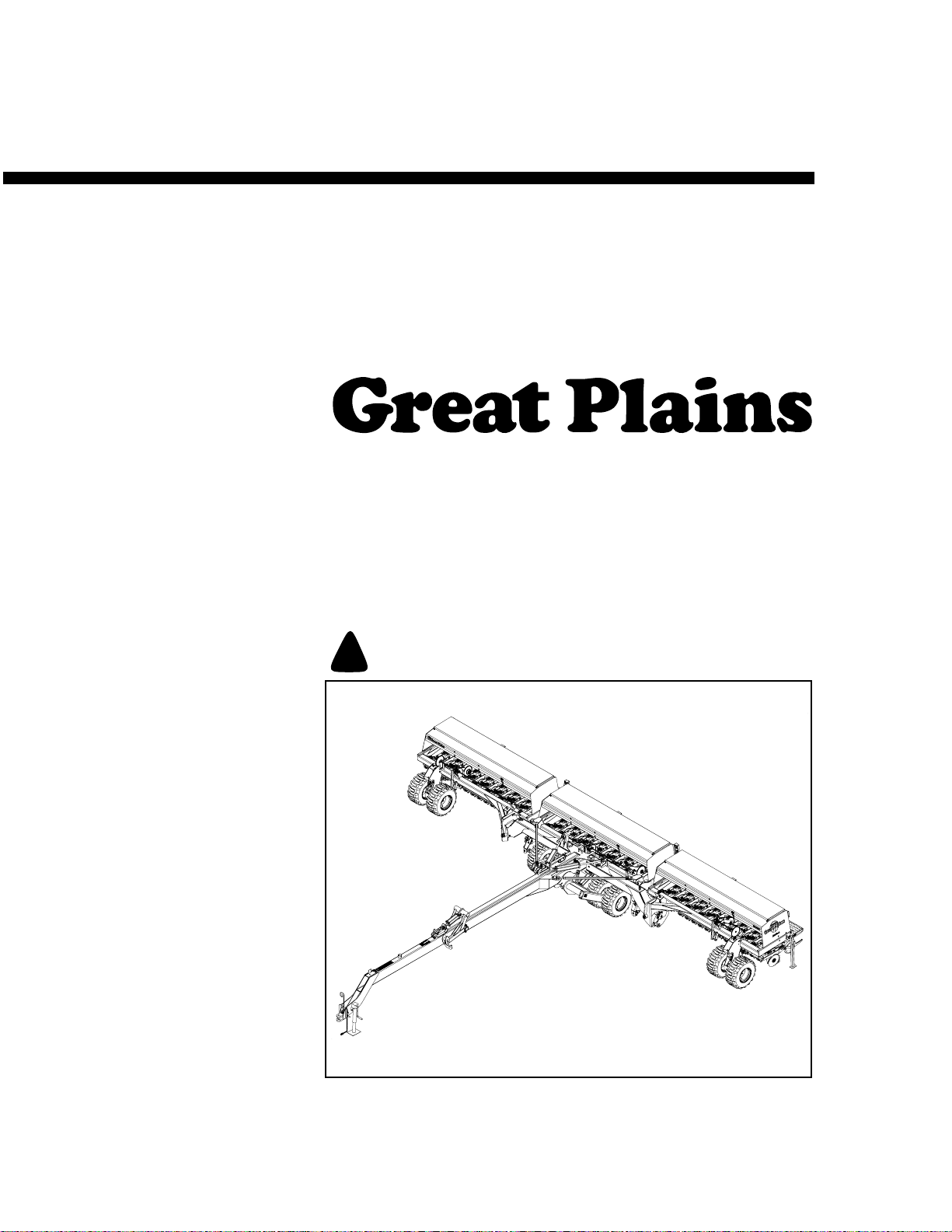
Cover illustration may show optional equipment not supplied with standard unit.
© Copyright 2009 Printed 9/10/2009
195-242Q
Page 2

Table of Contents
Important Safety Information . . . . . . . . . . . . . 1
Introduction . . . . . . . . . . . . . . . . . . . . . . . . . . . 4
Description of Unit . . . . . . . . . . . . . . . . . . . 4
Using This Manual . . . . . . . . . . . . . . . . . . . 5
Definitions . . . . . . . . . . . . . . . . . . . . . . 5
Assembly and Setup Assistance . . . . . . . . 5
Tools Required . . . . . . . . . . . . . . . . . . . . . . 6
Assembly . . . . . . . . . . . . . . . . . . . . . . . . . . . . . 6
Pre-Assembly Checklist . . . . . . . . . . . . . . . 6
Installing Middle Box on Frame. . . . . . . . . . 7
Installing Press Wheels . . . . . . . . . . . . . . . 8
Installing Walkboards . . . . . . . . . . . . . . . . . 9
Installing Reflectors and Decals . . . . . . . . 10
Post Assembly Checklist. . . . . . . . . . . . . . 11
Setup . . . . . . . . . . . . . . . . . . . . . . . . . . . . . . . 12
Hitching Tractor to Drill . . . . . . . . . . . . . . . 12
Hydraulic Hose Hookup . . . . . . . . . . . . . . 14
Bleeding Hydraulics . . . . . . . . . . . . . . . . . 15
Bleeding Opener Lift Hydraulics. . . . . 16
Bleeding Fold Hydraulics.. . . . . . . . . . 17
Bleeding Transport Lift Hydraulics. . . 18
Bleeding Marker Hydraulics . . . . . . . . 19
Folding . . . . . . . . . . . . . . . . . . . . . . . . . . . 20
Unfolding. . . . . . . . . . . . . . . . . . . . . . . . . . 21
Quick Reference. . . . . . . . . . . . . . . . . 21
Leveling the Drill . . . . . . . . . . . . . . . . . . . . 22
Center Box Frame Leveling . . . . . . . . 22
Frame Adjustments. . . . . . . . . . . . . . . . . . 23
Toolbar Height Adjustment . . . . . . . . . 23
Truss Tube . . . . . . . . . . . . . . . . . . . . . 23
Wing Box Alignment . . . . . . . . . . . . . . 24
Opener Frame Clearance. . . . . . . . . . 24
Align Transfer Drive Shaft . . . . . . . . . . 25
Install Final Accessories . . . . . . . . . . . . . . 27
Acremeter Installation. . . . . . . . . . . . .27
Appendix . . . . . . . . . . . . . . . . . . . . . . . . . . . . 28
Torque Values Chart . . . . . . . . . . . . . . . . . 28
Tire Inflation Chart . . . . . . . . . . . . . . . . . . 29
Hydraulic Schematics . . . . . . . . . . . . . . . . 29
© Copyright 2001, 2009 All rights Reserved
Great Plains Manufacturing, Inc. provides this publication “as is” without warranty of any kind, either expressed or implied. While every precaution has been taken in the
preparation ofthis manual,Great PlainsManufacturing, Inc.assumes noresponsibility for errors or omissions. Neither is any liability assumed for damages resulting from
the use of the information contained herein. GreatPlains Manufacturing, Inc. reserves theright to revise and improve its products as it sees fit. This publication describes
the state of this product at the time of its publication, and may not reflect the product in the future.
The following are trademarks of Great Plains Mfg., Inc.: Application Systems, Ausherman, Land Pride, Great Plains
All other brands and product names are trademarks or registered trademarks of their respective holders.
195-242Q 9/12/2009
Great Plains Manufacturing, Incorporated Trademarks
Printed in the United States of America.
Page 3

Important Safety Information
For your safety, thoroughly read Important Safe-
ty Information in the operator’s manuals before
proceeding.
Look for Safety Symbol
The SAFETY ALERT SYMBOL indicates there is
a potential hazard to personal safety involved and
extra safety precaution must be taken. When you
see this symbol, be alert and carefully read the
message that follows it. In addition to design and
configuration of equipment, hazard control and
accident prevention are dependent upon the
awareness, concern, prudence and proper training of personnel involved in the operation,
transport, maintenance and storage of
equipment.
Important Safety Information
!
1
Be Aware of Signal Words
Signal words designate a degree or level of hazard seriousness.
DANGER indicates an imminently hazardous situation which, if not avoided, will result in death or
serious injury. This signal word is limited to the
most extreme situations, typically for machine
components that, for functional purposes, cannot
be guarded.
WARNING indicates a potentially hazardous situation which, if not avoided, could result in death or
serious injury, and includes hazards that are exposed when guards are removed. It may also be
used to alert against unsafe practices.
CAUTION indicates a potentially hazardous situation which, if not avoided, may result in minor or
moderate injury. It may also be used to alert
against unsafe practices.
DANGER
!
WARNING
!
CAUTION
!
9/12/2009
195-242Q
Page 4

2
3S-4000
Avoid High Pressure Fluids
Escaping fluid under pressure can penetrate the
skin, causing serious injury.
▲ Avoid the hazard by relieving pressure before
disconnecting hydraulic lines.
▲ Use a piece of paper or cardboard, NOT
BODY PARTS, to check for suspected leaks.
▲ Wear protective gloves and safety glasses or
goggles when working with hydraulic systems.
▲ If an accident occurs, see a doctor immedi-
ately. Any fluid injected into the skin must be
surgically removed within a few hours or gangrene may result.
Practice Safety
▲ Understand procedure before doing work. Use
proper tools and equipment.
▲ Work in a clean, dry area.
▲ Inspect all parts. Make sure parts are in good
condition and installed properly.
▲ Remove all tools and unused parts from drill
before operation.
Prepare for Emergencies
▲ Be prepared if a fire starts.
▲ Keep a first aid kit and fire extinguisher handy.
▲ Keep emergency numbers for doctor, ambu-
lance, hospital and fire department near
phone.
911
195-242Q
9/12/2009
Page 5
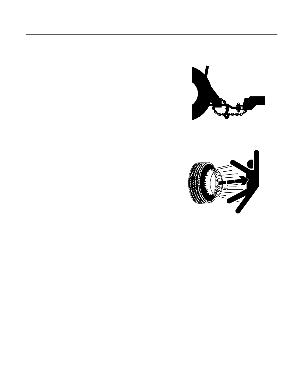
Use A Safety Chain
▲ Use a safety chain to help control drill should
it separate from tractor drawbar.
▲ Use a chain with a strength rating equal to or
greater than the gross weight of drill.
▲ Attach chain to tractor drawbar support or
other specified anchor location. Allow only
enough slack in chain to permit turning.
▲ Replace chain if any links or end fittings are
broken, stretched or damaged.
▲ Do not use safety chain for towing.
Tire Safety
Tire changing can be dangerous and should be
performed by trained personnel using correct
tools and equipment.
Important Safety Information
3
▲ When inflating tires, use a clip-on chuck and
extension hose long enough to you to stand
to one side–not in front of or over tire assembly. Use a safety cage if available.
▲ When removing and installing wheels, use
wheel-handling equipment adequate for
weight involved.
9/12/2009
195-242Q
Page 6

4
3S-4000
Introduction
Great Plains Manufacturing wants you to be satisfied with any new machine delivered by the Great
Plains Trucking network. To ease the assembly
task and produce a properly working machine,
read this entire manual before assembling or setting up new equipment.
Description of Unit
The 3S-4000 is a towed seeding implement. This
three section drill has a working width of 40 feet.
The drill has straight arm, double disk openers.
The opener disks make a seed bed, and seed
tubes mounted between the disks place seed in
the furrow. Press wheels following the opener
disks close the furrow and gauge opener seeding
depth. A T-handle on the opener body is for seeding depth adjustments. Seeding rates are
adjustable with the seed rate adjustment handle
and sprocket changes.
The 3S-4000 features active hydraulic down pressure on the opener frames. When used on a
tractor with closed-center hydraulics, constant
down pressure ensures even opener penetration
in uneven ground. Hydraulic down pressure is adjustable at a single point.
Intended Usage
Use this implement to seed production-agriculture
crops in conventional or minimum tillage
applications.
Models Covered
3S-4000
18843
3S-4000
195-242Q
9/12/2009
Page 7

Using This Manual
This manual was written to help you assemble
and prepare the new machine for the customer.
The manual includes instructions for assembly
and setup. Read this manual and follow the recommendations for safe, efficient and proper
assembly and setup.
An operator’s manual is also provided with the
new machine. Read and understand Important
Safety Information and Operating Instructions
in the operator’s manual before assembling the
machine. As a reference, keep the operator’s
manual on hand while assembling.
The information in this manual is current at printing. Some parts may change to assure top
performance.
Introduction
5
Definitions
The following terms are used throughout this
manual.
Right and left as used in this manual are determined by facing the direction the machine will
travel while in use unless otherwise stated.
IMPORTANT: A crucial point of information
about the precedingtopic. For safe and correct
operation, read and follow the directions provided before continuing.
NOTE: Useful information about the preceding
topic.
Assembly and Setup Assistance
To order additional copies of predelivery instructions or operator’s and parts manuals, write to the
following address. Include model numbers in all
correspondence.
If you do not understand any part of this manual or
have other assembly or setup questions, assistance is available. Contact
9/12/2009
Product Support
Great Plains Mfg. Inc., Service Department
P.O. Box 5060
Salina, KS 67402-5060
195-242Q
Page 8
6
3S-4000
Assembly
The following headings are step-by-step instructions for assembling the 4000-3S drill. Begin with
“Tools Required” and “Pre-Assembly Checklist” to
make sure you have all necessary parts and
equipment. Follow each step to make the job as
quick and safe as possible and produce aproperly
working machine.
The 4000-3S drill is shipped via flat bed truck. It is
the dealer’s responsibility to unload the new machine. Unload all equipment before beginning
assembly. Do not attempt any assembly work
while the 4000-3S drill is on the truck.
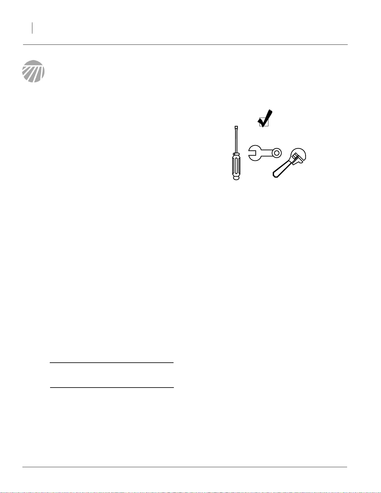
Tools Required
• Fork lift, overhead hoist, or loader
• General hand tools
Pre-Assembly Checklist
1. Before assembling, read and understand “Important Safety Information,” beginning on
page 1.
2. Have at least two people on hand while assembling.
3. Make sure assembly area is level and free of
obstructions (preferably an open concrete area).
4. Have all major components.
5. Have all fasteners and pins shipped with the
drill.
IMPORTANT: If a pre-assembled part or fastener is temporarily removed, remember
where it goes. Keep the parts separated.
195-242Q
6. Have a copy of the parts manual on hand. If
unsure of proper placement or use of any part
or fastener, refer to the parts manual.
9/12/2009
Page 9
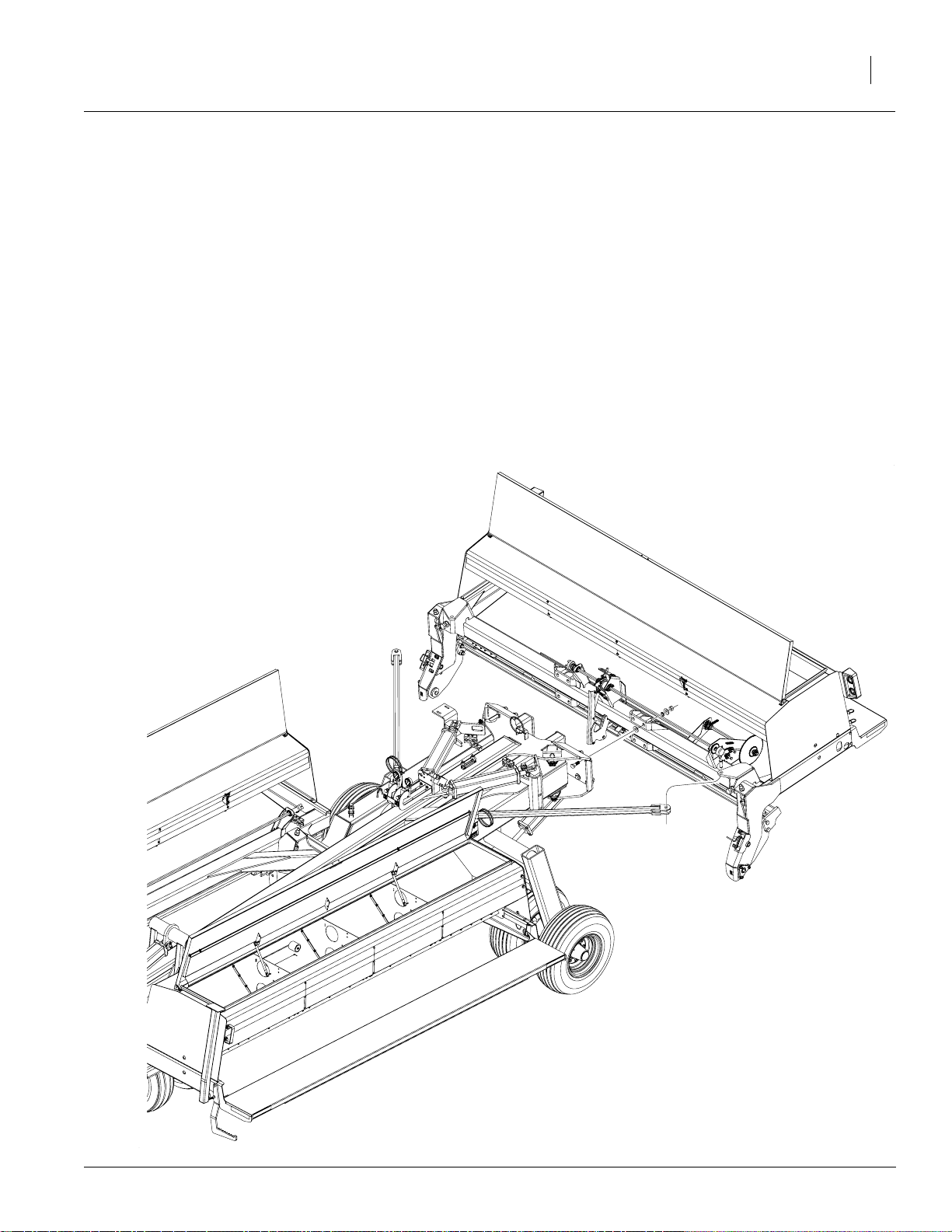
Installing Middle Box on Frame
1. With forklift chains secured around lifting bar
on back of center section box, lift center section box up to folded drill.
2. Bolt center section to drill tongue as shown
using 7/8-inch bolts, flat washers, lock washers and nuts.
3. Connect truss tubes to center section as
shown using clevis pins. Secure clevis pins
with cotter pins provided. Take looseness out
of truss by adjusting turnbuckle, but do not
overtighten.
Assembly
7
9/12/2009
19115
195-242Q
Page 10
8
3S-4000
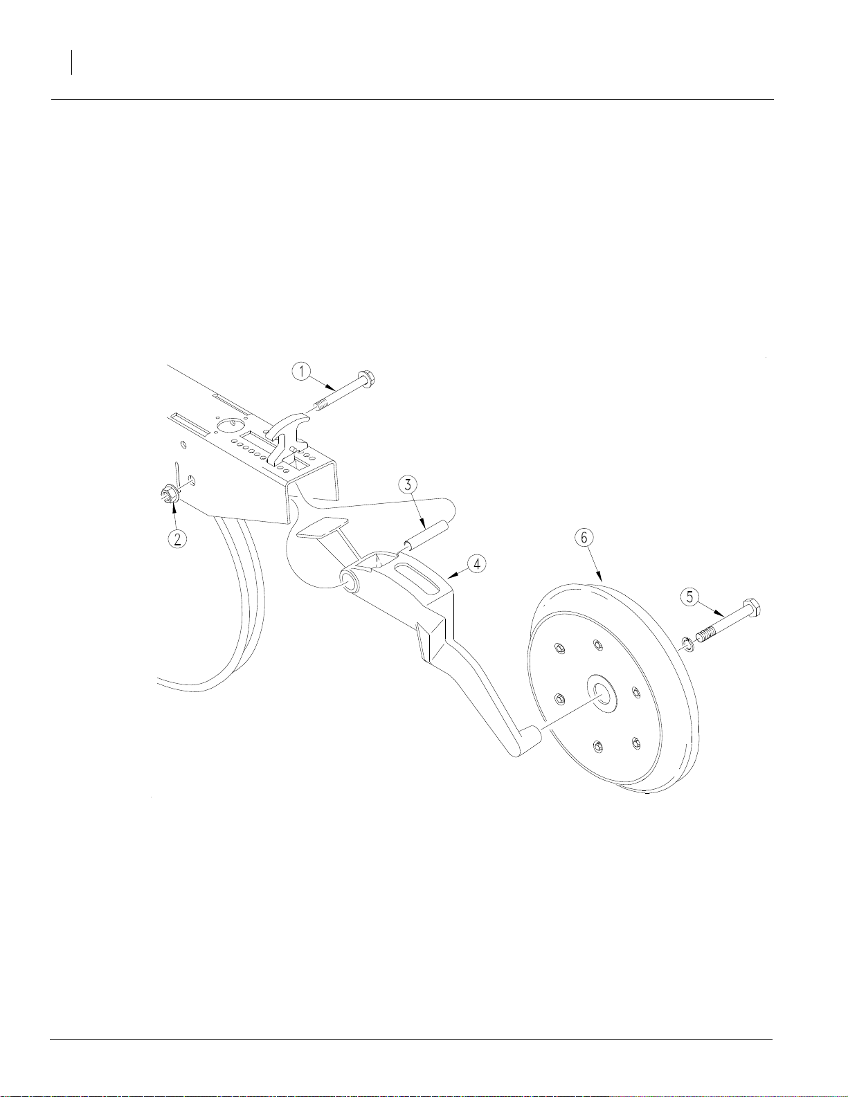
Installing Press Wheels
1. Remove 1/2 x 3-3/4 inch flange bolt (1) and
flange lock nut (2) from each opener body.
2. Leave pivot bushing (3) in place and bolt
press wheel arm (4) to opener with 1/2 x
3-3/4 inch flange bolt (1) and lock nut (2). Repeat for all openers.
3. Remove 5/8 inch bolt (5) from each press
wheel arm (4) and use bolts to assemble
press wheels (6) to press wheel arms.
195-242Q
18928
9/12/2009
Page 11
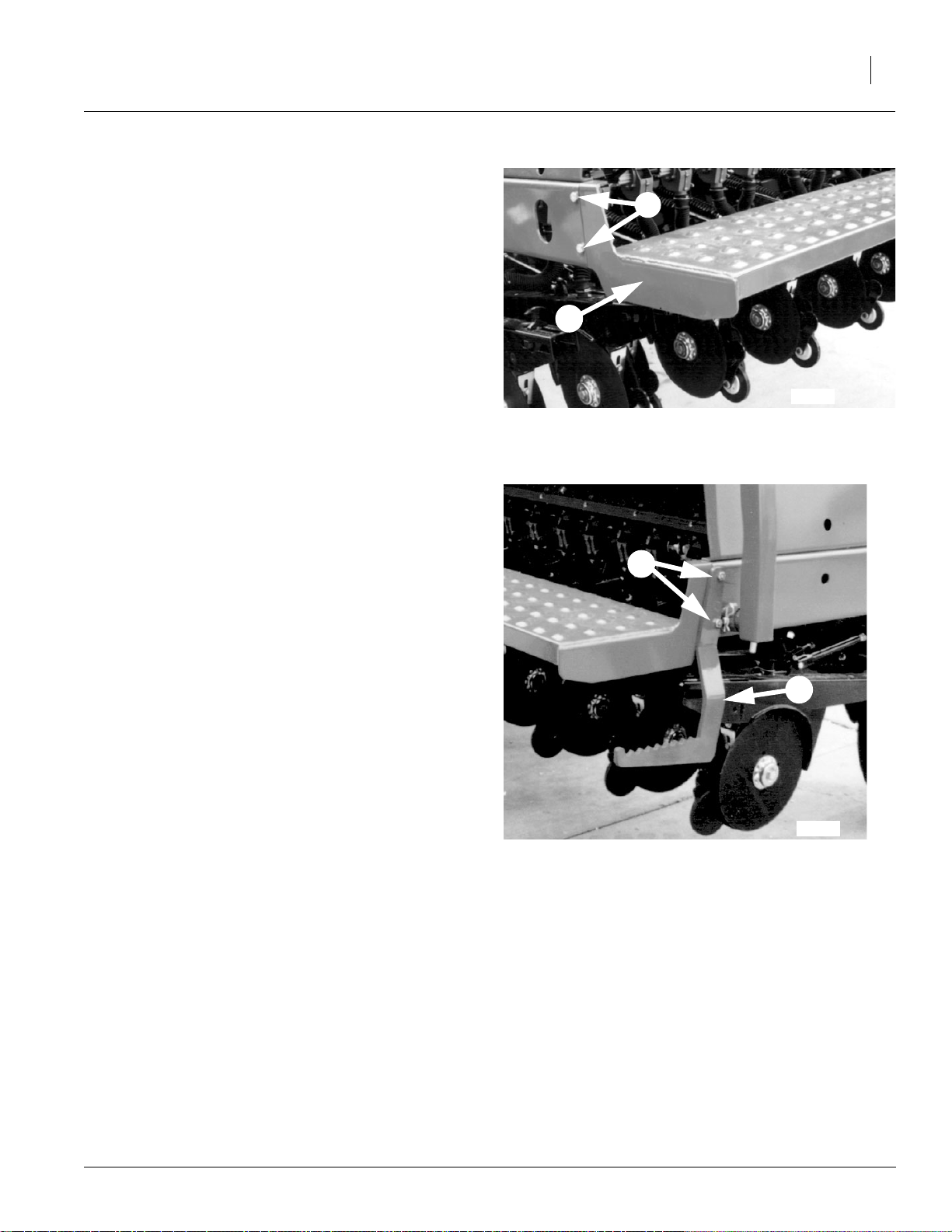
Installing Walkboards
Bolts for walkboards are shipped ina bag in one of
the drill boxes.
Bolt walkboards (1) to box support channels.
Use the 1/2 x 1-1/4 inch bolts (2), lock washers
nand hex nuts on inside of wings and on center
section.
Use the 1/2 x 1-3/4 inch bolts (3), lock washers
and hex nuts to bolt the walkboard and step (4) on
outside ends of wings.
Assembly
9
2
1
18921
NOTE: The steps (4) are not interchangeable.
Bolt steps so that steps jog away from the end
panel and extend back.
3
4
18920
9/12/2009
195-242Q
Page 12

10
3S-4000
Installing Reflectors and Decals
Decals are shipped in a bag in one of the drill
boxes.
To install new reflectors and decals:
• Clean the area where the reflector or decal is
to be placed.
• Peel backing from reflector or decal. Press
firmly on surface, being careful not to cause
air bubbles under reflector or decal.
Place decals as follows.
1. On outside end of walkboard on each wing
section, place amber reflectors and decal
#838-102C as shown. On outside end of center section, place amber decal only.
2. On the backside of wing walkboards, place
the amber reflectors as shown.
Decal
#838-102C
3. One back of center section, place a red
reflector and a daytime reflector as
shown.
4. On inside end of walkboard on each
wing section, place amber reflector as
shown.
Center
Amber
Reflector
section
Daytime
reflector
Right
wing
Redr
reflector
18837
section
Amberr
reflector
195-242Q
18871
9/12/2009
Page 13

Acremeter
Assemble acremeter (1) to end of main drive shaft
on the center section as shown.
Post Assembly Checklist
1. Check that all working parts are moving freely, bolts are tight, and cotter pins are spread.
Assembly
1
11
18922
2. Check for proper tension and alignment on all
drive chains.
3. Check that all safety decals and reflectors are
located correctly and legible. Replace if improperly located or damaged. Refer to “Safety
Decals” in the operator’s manual.
4. Inflate tires to recommended pressure as listed on the “Tire Inflation Chart,” page 29.
Tighten wheel bolts as specified on “Torque
Values Chart,” page 28.
9/12/2009
195-242Q
Page 14

12
!
!
3S-4000
Setup
Hitching Tractor to Drill
DANGER
You may be severely injured or killed by being crushed
between the tractor and drill. Do not stand or place
any part of your body between drill and moving tractor. Stop tractor engine and set park brake before installing the hitch pin.
WARNING
This drill can have positive and negative tongue
weight, which can work the hitch pin loose during
transport. To avoid serious injury or death due to a
road accident, always use a clevis hitch or clevis drawbar with a locking-style hitch pin.
1. Choose a drill-hitch option that is compatible
with your tractor drawbar.
The 3S-4000 has three hitch options:
• a clevis hitch,
• a small-hole, single-strap hitch or
• a large-hole, single-strap hitch.
Use the clevis hitch with tractors that have
single-tang drawbars.Use the single-strap
hitch for tractors with clevis drawbars. Always
use a locking-style hitch pin sized to match
the holes in the hitch and drawbar.
2. To adjust the drill hitch to match your tractordrawbar height, mount tongue jack on side of
tongue as shown. Use jack to raise drill
tongue so lowest hitch hole is 18 inches off
ground.
18941
195-242Q
9/12/2009
Page 15

3. Bolt drill hitch onto drill tongue to match your
tractor-drawbar height. You can turn the hitch
over for a total of six different hitch heights.
Setup
18956
13
NOTE: When hitching drill to a different tractor,
check for a difference in drawbar heights. If
heights are different, readjust hitch height accordingly.
4. Securely attach safety chain to an anchor on
a tractor capable of pulling the drill.
5. Store jack on top of tongue as shown.
6. Plug drill electrical lead in tractor seven-pin
connector. If your tractor is not equipped with
a seven-pin connector, contact yourdealer for
installation.
9/12/2009
18940
195-242Q
Page 16

14
!
3S-4000
Hydraulic Hose Hookup
WARNING
Escaping fluid under pressure can penetrate the skin
causing serious injury. Avoid the hazard by relieving
pressure before disconnecting hydraulic lines. Use a
piece of paper or cardboard, NOT BODY PARTS, to
check for suspected leaks. Wear protective gloves and
safety glasses or goggles when working with hydraulic
systems. If an accident occurs, see a doctor immediately. Any fluid injected into the skin must be surgically
removed within a few hours or gangrene may result.
IMPORTANT: To run drill in the field on tractors with open-center hydraulics or on tractors with fixed-displacement hydraulic
pumps, you must install a Great Plains kit,
part number 194-143A. You can set up drill
and bleed hydraulics with either an open- or
closed-center system.
Color Hydraulic Function
Red Opener Lift Cylinders
Great Plains hydraulic hoses are color coded to
help you hookup hoses to your tractor outlets.
Hoses that go to the same remote valve are
marked with the same color.
To distinguishhoses on thesame hydraulic circuit,
refer to plastic hose holder. Hose under extendedcylinder symbol feeds cylinder base ends. Hose
under retracted-cylinder symbol feeds cylinder
rod ends.
1. Connect opener-lift hoses to circuit designated for hydraulic-motor control.
2. Connect transport-lift hoses to tractor remote
valve.
3. Connect fold hoses to tractor remote valve.
NOTE: If your tractor has only two remote valves,
you must install a double-selector valve to combine the transport-lift and opener-lift circuits. Refer to Two Outlet Hydraulic Kit, Great Plains Part
Number 194-122A, in the operator’s manual.
Blue Transport Lift Cylinders
White Fold Cylinders
Orange Marker Cylinders
Table 1
17641
195-242Q
9/12/2009
Page 17

Bleeding Hydraulics
!
!
To function properly, the hydraulics must be free of
air. If hydraulics have not been bled, they will operate with jerky, uneven motions and could cause
wings to drop rapidly during folding or unfolding.
Complete the following procedures during initial
drill setup.
WARNING
Raising openers on unfolded, unhitched drill will
cause drill tongue to rise suddenly, which could cause
serious injury or death. Be certain that drill is hitched
securely to your tractor drawbar and the safety chain
is securely attached to tractor before raising openers
and unfolding drill.
Setup
15
WARNING
Escaping fluid under pressure can penetrate the skin
causing serious injury. Avoid the hazard by relieving
pressure before disconnecting hydraulic lines. Use a
piece of paper or cardboard, NOT BODY PARTS, to
check for suspected leaks. Wear protective gloves and
safety glasses or goggles when working with hydraulic
systems. If an accident occurs, see a doctor immediately. Any fluid injected into the skin must be surgically
removed within a few hours or gangrene may result.
9/12/2009
195-242Q
Page 18

16
3S-4000
Bleeding Opener Lift Hydraulics
1. Check hydraulic fluid level in tractor reservoir
and fill to proper level. Add fluid to system as
needed. System capacity for entire drill is
about 4 1/2 gallons.
2. Make sure opener frames are locked up in
road position. Refer to Opener Lock Up in the
operator’s manual.
3. Turn knob on both pressure-control valves
completely counterclockwise, then turn
valves clockwise far enough to build up 1000
psi (about three turns).
4. Turn knob on bypass valve (1) completely
clockwise for no oil flow.
5. Loosen six hose-end fittings (2) at the locations shown.
NOTE: Do not loosen an O-ring fitting for bleeding. Bleeding air from an O-ring fitting will damage
the seal.
6. Slowly supply oil to top side of pressure-control valves until oil begins to appear at a loosened hose fitting. As oil begins to appear at a
fitting, tighten that fitting.
7. Slowly supply oil to bottom side of pressurecontrol valves until oil begins to appear at remaining loosened hose fitting. As oil begins to
appear at the fitting, tighten fitting. Continue
to supply oil to bottom side of pressure-control valves until all openers are raised completely.
8. Move opener transport locks to field position
and cycle openers up and down ten times.
Each time you lower openers, hold tractor remote lever until opener circuit builds up to
pressure set at control valves.
9. After cycling openers, return openertransport
locks to road position.
195-242Q
20000
9/12/2009
Page 19

Setup
17
Bleeding Fold Hydraulics.
1. Check hydraulic fluid level in tractor reservoir
and fill to proper level. Add fluid to system as
needed.
2. With drill unfolded and fold cylinders completely extended, disconnect rod end pins
and swing the cylinders so they will not contact anything when extended.
3. Loosen rod end hose fitting at elbow on right
fold cylinder (1).
NOTE: Do not loosen an O-ring fitting for bleeding. Bleeding air from an O-ring fitting will damage
the seal.
4. Slowly supply oil to rod end of fold cylinders
until oil appears at loosened hose fitting.
Tighten fitting and completely retract fold cylinders.
5. With cylinders completely retracted, loosen
base end hose fitting at elbow on right fold cylinder (2).
6. Slowly supply oil to base end of fold cylinders
until oil appears at loosened hose fitting.
Tighten base end hose fitting and cycle fold
cylinders in and out several times.
7. Repin cylinder rod clevis.
9/12/2009
18958
195-242Q
Page 20

18
!
3S-4000
Bleeding Transport Lift Hydraulics.
1. Check hydraulic fluid level in tractor reservoir
and fill to proper level. Add fluid to system as
needed.
2. Lower drill into field position and completely
retract box lift cylinder at middle of tongue.
Loosen base end hose fitting on left transport
lift cylinder and base end fitting on box lift cylinder (1).
3. Slowly supply oil to base end of transport lift
cylinders until oil appears at loosened hose
fitting. Oil may not appear at both locations at
the same time. As oil begins to appear at a fitting, tighten that fitting and proceed until both
fittings have been tightened.
4. Completely extend transport lift cylinders and
immediately lock cylinders up by flipping up
cylinder lock channels on both transport lift
cylinders and box lift cylinder.
WARNING
The hydraulics could fail, causing the openers to fall
and crush you. To prevent serious injury or death, always secure cylinder lock channels over extended
transport-lift cylinders before working under openers.
5. When cylinder lock channels are in place,
loosen rod end hose fitting on left transport lift
cylinder and rod end hose fitting on box lift cylinder (2).
6. Slowly supply oil to rod end of transport lift
cylinders until oil appears at the loosened
hose fittings. As oil begins to appear at fitting,
tighten that fitting and proceed until all fittings
are tightened.
7. Extend transport lift cylinders, and remove
the cylinder lock channels. Completely cycle
transport lift hydraulics several times.
195-242Q
18836
9/12/2009
Page 21

Bleeding Marker Hydraulics
!
CAUTION
You may be injured if hit by a folding or unfolding
marker. Markers may fall quickly and unexpectedly if
the hydraulics fail. Never allow anyone near the drill
when folding or unfolding markers.
1. Make sure tractor hydraulic reservoir is full.
2. With markers unfolded in field position, crack
hydraulic-hose fittings at base and rod ends
of each marker cylinder.
3. With tractor at idle speed, activate tractor hydraulic valve forward until oil appears at one
fitting. When oil begins to seep out around a
fitting, tighten that fitting. Reverse the tractor
hydraulic valve until oil appears at opposite
hose fitting and tighten that fitting.
4. If you have dual markers, activate your tractor
hydraulic valve forward again until oil seeps
out around one fitting on the other marker cylinder and tighten that fitting. Reverse tractor
hydraulic valve until oil seeps out around remaining hose fitting and tighten it.
5. Fold and unfold markers slowly to work out all
air.
NOTE: Use caution when folding and unfolding
markers for the first time, checking for pinching
and kinking of hoses.
Setup
19
9/12/2009
195-242Q
Page 22

20
!
3S-4000
Folding
WARNING
Crushing hazard – Bystanders could be crushed between the folding drill boxes and the drill tongue. To
avoid serious injury or death, keep all bystanders well
away during drill operation.
1. Park tractor and drill on level ground with tractor transmission in park. Be aware of clearance needed to fold drill.
2. Position opener lock handles in road position
and as shown in Figure 1 and completely
raise openers.
NOTE: The opener transport lock handles are
spring loaded and can be moved to road position
with openers up or down, but locks will only engage when openers are completely raised. There
are two locks on each drill section.
3. Make sure transport lift cylinders and front
box lift cylinder are completely retracted.
4. Slowly supply oil to rod end of fold circuit.
Completely fold wing frames until both wing
gauge wheels contact tongue tube.
Figure 1
Opener Lock Up
15549
5. Supply oil to transport lift circuit until transport
lift cylinders and front box lift cylinder are
completely extended and drill is completely
raised.
6. Refer to Figure 2. Rotate cylinder lock channels over rods on the two transport lift cylinders and the front box lift cylinder.
IMPORTANT: The channels will remain in position when cylinders settle against channels.
7. Allow transport lift cylinders to settle back
against lock channels.
8. Before transporting, check that hydraulic cylinders are holding lock channels securely.
Transport Lift
Cylinder Lock
18960
Front Box Lift
Cylinder Lock
195-242Q
Figure 2
Cylinder Lock Channels Inserted for Transport
9/12/2009
18959
Page 23

Unfolding
1. Park tractor and drill on level ground with trac-
tor transmission in park. Be aware of clearance needed to unfold drill.
2. Supply oil to transport lift circuit until transport
lift cylinders and front box lift cylinder are
completely extended and drill is raised completely.
3. Rotate cylinder lock channels off cylinder
rods of transport lift cylinders and front box lift
cylinder. See Figure 3.
4. Completely retract transport lift cylinders and
front box lift cylinder.
5. Slowly supply oil to base end of fold circuit.
Unfold wing frames by completely extending
fold cylinders.
Transport Lift
Cylinder Lock
Setup
18960
21
6. Position opener transport lock handles in field
position. See Figure 4.
7. Completely raise openers to allow opener
transport locks to disengage.
NOTE: The opener transport lock handles are
spring loaded and can be moved to field position
with openers up or down, but locks will only disengage when openers are completely raised. There
are two lock handles on each drill section.
Folding and Unfolding Quick
Reference
To Fold Drill
1. Raise openers.
2. Fold drill
3. Extend transport and front box lift cylinders.
4. Lock transport and front box lift cylinders.
To Unfold Drill
1. Completely extend transport and front box lift
cylinders.
Front Box Lift
Cylinder Lock
Figure 3
Transport Cylinder Lock Channels Removed
18959
9/12/2009
2. Unlock transport and front box lift cylinders.
3. Retract transport and front box lift cylinders.
4. Unfold drill.
5. Lower openers.
Figure 4
Opener Unlock
15548
195-242Q
Page 24

22
3S-4000
Leveling the Drill
Center Box Frame Leveling
1. Park the drill on a clean level surface.
2. Raise the openers and lock them up.
3. Loosen the eight center box mount bolts (1),
four bolts on each side of tongue, see Figure
5, and slide center box frame sideways until it
is centered with mainframe and transport axle.
4. See Figure 6. Measure the height of center
box opener frame pivots (2) from the level surface and raise low end of box frame up until
both opener frame pivots measure the same
distance from the ground.
5. Torque the 7/8 inch box mount bolts (1), Figure 5.
1
Figure 5
Center Box Mount Bolts
1
18873
Opener
pivot
2
frame
height
Figure 6
Opener Frame Leveling
18874
195-242Q
9/12/2009
Page 25

Setup
23
Frame Adjustments
Toolbar Height Adjustment
Toolbar height is factory set and normally will not
require adjustment. If the toolbar is visibly not level, spacer washers on vertical pivot pins allow for
a small amount of toolbar-height adjustment.
Refer to Figure 7.
To check toolbar height, park drill on a level surface. Measure from ground to horizontal pivot pin
(1). If dimension on either side of drill varies more
than 1/4 inch, adjust toolbar height.
To adjust toolbar height, reposition spacer washers (2). First lower openers and set enough
opener down pressure to help balance frame.
Raise toolbar by removing spacer washers from
top of the vertical pivot and placing them on bottom side of pivot. Lower toolbar by removing
spacer washers from bottom of vertical pivot and
placing them on top of pivot.
Truss Tube
Refer to Figure 7.
Provide a small amount of tension on truss tube to
help hold draft load from tool bars.
Link Tube
3
2
1
T
oolbar Height
4
18845
Figure 7
Toolbar and Link Tube Adjustments
9/12/2009
195-242Q
Page 26

24
3S-4000
Wing Box Alignment
1. Place a block ahead of the wing gauge
wheels.
2. Pull forward against blocks to rock wing
frames back. Pull forward until stop bolts are
firmly against toolbars. Refer to Figure 8 for
stop bolt location.
3. Check for proper alignment by running a
string line across back of drill toward outer
ends of wings. For proper alignment, outside
ends of boxes should be about 1 inch to 1-1/4
inch ahead of inside ends. See Figure 9.
4. To adjust box alignment, shorten or lengthen
stop bolts to change the contact point with the
toolbars. Adjust stop bolts in or out until outside ends of boxes are 1 inch to 1-1/4 inch
ahead of inside ends.
Stop Bolt
Figure 8
Stop Bolt Location
C-B=1 to 1-1/4 inch
C
String Line
Support
B
Opener Frame Clearance
Refer to Figure 10.
When fully raised, top of opener mounts (1)
should clear bottom of drill frame tube by at least
1/2 inch.
A
String Line
Figure 9
Wing Box Alignment Measurement
C
String Line
B
A
Support
15654
2
195-242Q
To adjust opener frames so all openers have the
same clearance, loosen jam nut (2) on opener lift
cylinders and turn adjustment nut. When openers
are at the correct height, retighten jam nut. Repeat at each opener lift cylinder if necessary.
1
Figure 10
Opener Frame Clearance
18853
9/12/2009
Page 27

Align Transfer Drive Shaft
After wing boxes are properly aligned, the transfer
drive shaft must be aligned so the pair of breakaway jaws are fully engaged and are concentric.
The 7/8 inch hex drive shafts holding the clutch
jaws should not contact each other when wing
boxes are properly aligned and back against their
stops.
1. Place a 4x4 or similar sized block ahead of
the wing gauge wheels and pull forward or
push wing box frames back until the toolbar is
firmly against toolbar stop bolts on the center
box frame.
2. Refer to Figure 11. To align the clutch jaws
vertically, loosen the two 5/8 inch bolts (1) on
the backside of the adjustment plate (2). Slide
the plate up or down in the desired direction.
Setup
25
9/12/2009
Figure 11
Transfer Drive Shaft Vertical Adjustment
18953
195-242Q
Page 28

26
3S-4000
Refer to Figure 12.
3. To align the clutch jaws from front to rear,
loosen the two 1/2 inch carriage bolts (3) and
slide breakaway clutch (4) in the desired direction.
Transfer Drive Shaft Vertical Adjustment
4. To adjust clutch jaws for full jaw contact, loosen the two 1/2 inch carriage bolts (3) and slide
breakaway clutch (4) until jaws on the fixed
half of clutch make full contact with jaws on
spring loaded half of clutch without compressing clutch spring.
NOTE: The two 7/8 inch hex shafts (5) should
have 1/8 inch between them when the clutch jaws
have full contact. Refer to Figure 13.
Figure 12
Figure 13
Hex Shafts
18954
18955
195-242Q
9/12/2009
Page 29

Install Final Accessories
Acremeter Installation
Setup
27
Refer to Figure 14.
The acremeter is supplied from the factory in a sepa-
1
rate carton, to minimize risk of shipping damage. Check
to see if it has already been installed by your dealer. It is
located on the left end of the center main drive shaft.
If not already installed, screw the threaded end of the
meter into the
1
⁄
-20 tapped hole in the left end of
2
2
center main drive shaft.
Tighten the threaded end only enough to prevent it from
working loose from normal vibration. In use, there is no
torque or tension that might end to unscrew it.
The acremeter counts shaft rotations whenever the shaft
is rotating - normally this is only with the drill unfolded,
the opener sub-frame lowered, and the drill in motion.
The meter is geared to display rotations as acres, when
using factory-specified tires and inflations.
Tally field acres by noting the meter reading prior to, and
after planting. Subtract the starting from the ending
readings.
2
1
Figure 14
Acremeter Installation
27000
9/12/2009
195-242Q
Page 30

28
3S-4000
Appendix
Torque Values Chart for Common Bolt Sizes
Bolt Head Identification
Bolt Head Identification
Bolt Size
(Inches)
1
in-tpi
1/4" - 20 7.4 5.6 11 8 16 12 M 5 X 0.8 4 3 6 5 9 7
1/4" - 28 8.5 6 13 10 18 14 M 6 X 1 7 5 11 8 15 11
5/16 - 18 15 11 24 17 33 25 M 8 X 1.25 17 12 26 19 36 27
5/16" - 24 17 13 26 19 37 27 M 8 X 1 18 13 28 21 39 29
3/8" - 16 27 20 42 31 59 44 M10 X 1.5 33 24 52 39 72 53
3/8" - 24 31 22 47 35 67 49 M10 X 0.75 39 29 61 45 85 62
7/16" - 14 43 32 67 49 95 70 M12 X 1.75 58 42 91 67 125 93
7/16" - 20 49 36 75 55 105 78 M12 X 1.5 60 44 95 70 130 97
1/2" - 13 66 49 105 76 145 105 M12 X 1 90 66 105 77 145 105
1/2" - 20 75 55 115 85 165 120 M14 X 2 92 68 145 105 200 150
9/16" - 12 95 70 150 110 210 155 M14 X 1.5 99 73 155 115 215 160
9/16" - 18 105 79 165 120 235 170 M16 X 2 145 105 225 165 315 230
5/8" - 11 130 97 205 150 285 210 M16 X 1.5 155 115 240 180 335 245
5/8" - 18 150 110 230 170 325 240 M18 X 2.5 195 145 310 230 405 300
3/4" - 10 235 170 360 265 510 375 M18 X 1.5 220 165 350 260 485 355
3/4" - 16 260 190 405 295 570 420 M20 X 2.5 280 205 440 325 610 450
7/8" - 9 225 165 585 430 820 605 M20 X 1.5 310 230 650 480 900 665
7/8" - 14 250 185 640 475 905 670 M24 X 3 480 355 760 560 1050 780
1" - 8 340 250 875 645 1230 910 M24 X 2 525 390 830 610 1150 845
1" - 12 370 275 955 705 1350 995 M30 X 3.5 960 705 1510 1120 2100 1550
1-1/8" - 7 480 355 1080 795 1750 1290 M30 X 2 1060 785 1680 1240 2320 1710
1 1/8" - 12 540 395 1210 890 1960 1440 M36 X 3.5 1730 1270 2650 1950 3660 2700
1 1/4" - 7 680 500 1520 1120 2460 1820 M36 X 2 1880 1380 2960 2190 4100 3220
1 1/4" - 12 750 555 1680 1240 2730 2010
1 3/8" - 6 890 655 1990 1470 3230 2380
1 3/8" - 12 1010 745 2270 1670 3680 2710
1 1/2" - 6 1180 870 2640 1950 4290 3160
1 1/2" - 12 1330 980 2970 2190 4820 35604mm x pitch = nominal thread diameter in millimeters x thread pitch
Grade 2 Grade 5
N · m2ft-lb3N · m ft-lb N · m ft-lb mm x pitch4N · m ft-lb N · m ft-lb N · m ft-lb
Torque tolerance + 0%, -15% of torquing values. Unless otherwise specified use torque values listed above.
Grade 8
Bolt Size
(Metric)
1
in-tpi = nominal thread diameter in inches-threads per inch
5.8 8.8 10.9
Class 5.8 Class 8.8 Class 10.9
2
N· m = newton-meters
3
ft-lb= foot pounds
195-242Q
9/12/2009
Page 31

Tire Inflation Chart
Appendix
29
Tire Size Inflation
Tire Size Inflation
PSI
7.50 x 20" 4-Ply Drill Rib 28 11L x 15” 8=Ply Rib Implement 36
9.0 x 22.5 10-Ply Highway Service 70 70 11L x 15" 12-Ply Rib Implement 52
9.0 x 24" 8-Ply Rib Implement 40 12.5L x 15" 8-Ply Rib Implement 36
9.5L x 15" 6-Ply Rib Implement 32 12.5L x 15" 10-Ply Rib Implement 44
9.5L x 15" 8-Ply Rib Implement 44 12.5L x 15” 20-Ply Rib Implement 90
9.5L x 15" 12-Ply Rib Implement 60 16.5L x 16.1" 10-Ply Rib Implement 36
11L x 15" 6-Ply Rib Implement 28 41 x 15" x 18 - 22-Ply Rib Implement 44
Hydraulic Schematics
PSI
9/12/2009
Opener Hydraulics for Closed Center Systems
20002
195-242Q
Page 32

30
3S-4000
Hydraulic Schematics
195-242Q
20003
Opener Hydraulics for Open Center Systems
9/12/2009
Page 33

Hydraulic Schematics
Appendix
31
Transport Fold Hydraulics
15602
9/12/2009
Transport Lift Hydraulics
18931
195-242Q
Page 34

32
3S-4000
Hydraulic Schematics
Dual Marker Hydraulics
Single Marker Hydraulics
195-242Q
Kit for Tractors with Two Outlets
15605
9/12/2009
Page 35

Great Plains Manufacturing, Inc.
Corporate Office: P.O. Box 5060
Salina, Kansas 67402-5060 USA
 Loading...