

Page 1
Predelivery Manual
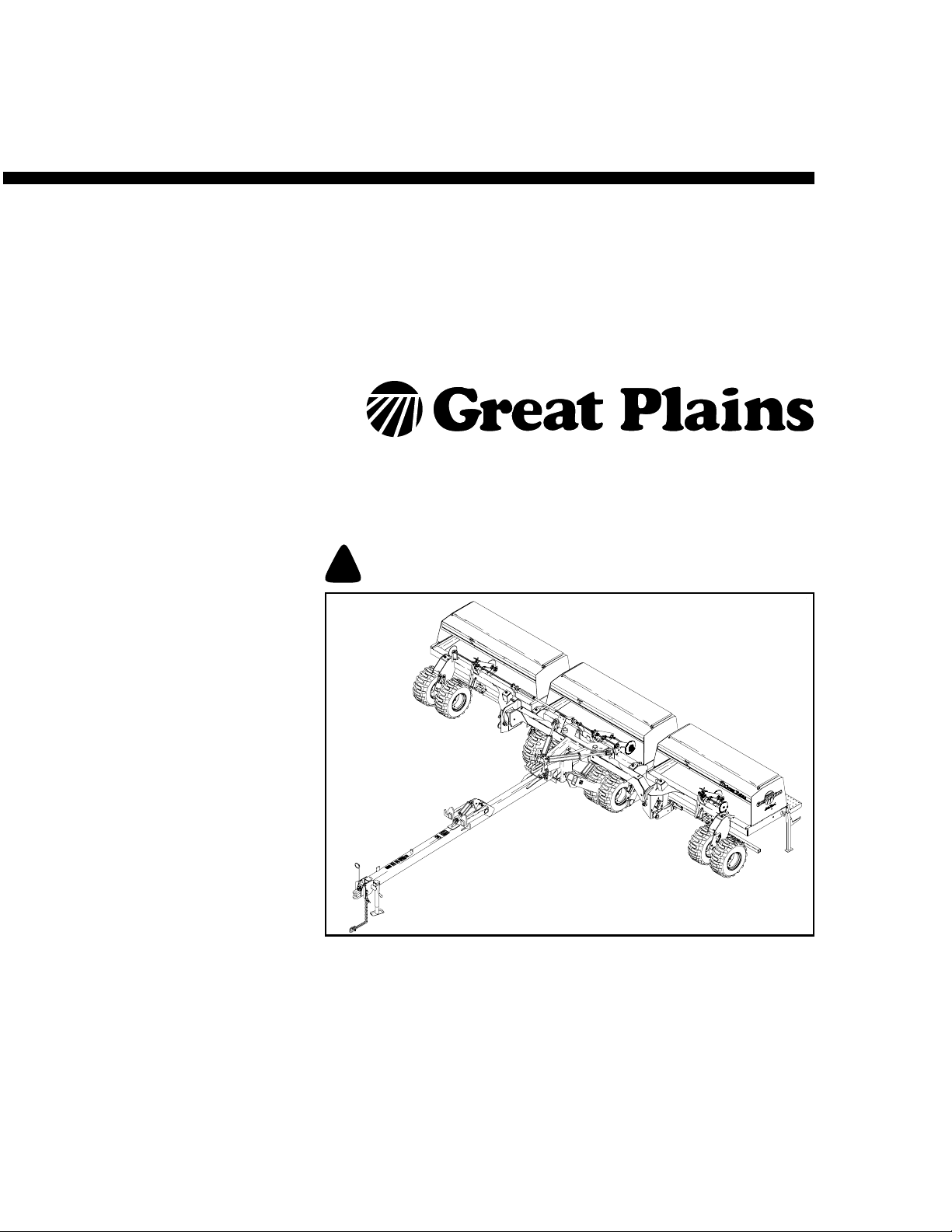
3S-3000HD
Three-Section Folding HD Drill
Manufacturing, Inc.
www.greatplainsmfg.com
Read the operator’s manual entirely. When you see this symbol, the subsequent
instructions and warnings are serious - follow without exception. Your life and
!
the lives of others depend on it!
15485
Cover illustration may show optional equipment not supplied with standard unit.
© Copyright 2009 Printed 12/09/2009 195-068Q
Page 2

3S-3000HD
Table of Contents
Important Safety Information.................................... 1
Introduction ................................................................ 4
Document Family ......................................................... 4
Description of Unit........................................................ 4
Intended Usage........................................................ 4
Models Covered....................................................... 4
Using This Manual ....................................................... 5
Definitions ................................................................5
Assembly and Setup Assistance.................................. 5
Preparation ................................................................. 6
Scope The Work .......................................................... 6
Wide Load Assembly ...............................................6
Standard “Legal” Load Assembly............................. 6
Overview of Work......................................................... 6
Assembly ................................................................. 6
Setup........................................................................ 6
Tools Required............................................................. 7
Pre-Assembly Checklist ............................................... 7
Assembly .................................................................... 8
Position for Assembly .................................................. 8
Assemble Tongue to Mainframe .................................. 8
Install Center Box on Frame ...................................... 10
Install Wing Box Frames ............................................ 11
Install Transfer Driveshaft .......................................... 12
Connect Opener Lift Hoses........................................ 13
Install Wing Walkboards and Steps ........................... 15
Walkboards with Single Steps ............................... 15
Walkboards with Swing-Down Ladders.................. 15
Install Swing-Down Ladders .................................. 16
Install Swing-Down Ladder Mounts.................... 16
Install Ladders.................................................... 17
Install Fixed Walkboard Steps ............................... 17
Install Reflectors and Decals ..................................... 18
Wing Walkboard Inner Decals................................ 18
Wing Fixed Step Decals......................................... 18
Wing Swing-Down Ladder Decals.......................... 19
Other Assembly Items................................................ 19
Install Press Wheels .............................................. 19
Two Outlet Kit ........................................................ 20
Markers.................................................................. 20
Open Center Conversion ....................................... 21
Point Row Option................................................... 21
Post Assembly Checklist ........................................... 21
Setup......................................................................... 22
Hitching...................................................................... 22
Electrical Connections ............................................... 24
Hydraulic Hose Hookup ............................................. 25
Bleeding Hydraulics ................................................... 26
Bleeding Fold Hydraulics ....................................... 27
Bleeding Opener Lift Hydraulics ............................ 28
Bleeding Transport Lift Hydraulics......................... 29
Bleeding Marker Hydraulics................................... 30
Leveling the Drill ........................................................ 31
Center Box Frame Leveling ................................... 31
Opener Frames Level ............................................ 31
Wing Box Alignment............................................... 32
Align Transfer Drive Shaft...................................... 33
Toolbar Height ....................................................... 35
Opener-Frame Clearance...................................... 36
Install Final Accessories ............................................ 36
Acremeter Installation ................................................ 36
Shaft Monitor.......................................................... 37
Point Row Controller.............................................. 37
Scraper Installation ................................................ 37
Appendix .................................................................. 38
Specifications and Capacities.................................... 38
Tire Inflation Chart ..................................................... 38
Torque Values Chart.................................................. 39
Hydraulic Diagrams ................................................... 40
Transport Lift.......................................................... 40
Fold........................................................................ 40
Dual Markers.......................................................... 41
Single Marker......................................................... 41
Two Outlet Conversion .......................................... 42
Opener Lift: Standard Closed-Center .................... 43
Opener Lift: Optional Open-Center........................ 44
Point-Row .............................................................. 45
© Copyright 1998, 2001, 2003, 2006, 2007, 2008, 2009. All rights Reserved
Great Plains Manufacturing, Inc. provides this publication “as is” without warranty of any kind, either expressed or implied. While every precaution has been taken in the preparation of this manual, Great Plains Manufacturing, Inc. assumes no responsibility for errors or omissions. Neither is any liability assumed for damages resulting from the use of
the information contained herein. Great Plains Manufacturing, Inc. reserves the right to revise and improve its products as it sees fit. This publication describes the state of this
product at the time of its publication, and may not reflect the product in the future.
The following are trademarks of Great Plains Mfg., Inc.: Application Systems, Ausherman, Land Pride, Great Plains
All other brands and product names are trademarks or registered trademarks of their respective holders.
195-068Q 12/09/2009
Great Plains Manufacturing, Incorporated Trademarks
Printed in the United States of America.
Page 3

Important Safety Information
For your safety, thoroughly read Important Safety
Information in the operator’s manuals before proceed-
ing.
Look for Safety Symbol
The SAFETY ALERT SYMBOL indicates there is a
potential hazard to personal safety involved and extra
safety precaution must be taken. When you see this
symbol, be alert and carefully read the message that follows it. In addition to design and configuration of equipment, hazard control and accident prevention are
dependent upon the awareness, concern, prudence and
proper training of personnel involved in the operation,
transport, maintenance and storage of equipment.
Be Aware of Signal Words
Signal words designate a degree or level of hazard seriousness.
DANGER indicates an imminently hazardous situation
which, if not avoided, will result in death or serious
injury. This signal word is limited to the most extreme situations, typically for machine components that, for functional purposes, cannot be guarded.
WARNING indicates a potentially hazardous situation
which, if not avoided, could result in death or serious
injury, and includes hazards that are exposed when
guards are removed. It may also be used to alert
against unsafe practices.
CAUTION indicates a potentially hazardous situation
which, if not avoided, may result in minor or moderate
injury. It may also be used to alert against unsafe practices.
1
12/09/2009 195-068Q
Page 4
2 3S-3000HD
Transport Machinery Safely
Maximum transport speed for drill is 20 mph (32 kph).
Some rough terrains require a slower speed. Sudden
braking can cause a towed load to swerve and upset.
▲ Do not exceed 20 mph (32 kph). Never travel at a speed
which does not allow adequate control of steering and
stopping. Reduce speed if towed load is not equipped with
brakes.
▲ Comply with national, regional and local laws.
▲ Follow your tractor manual recommendations for maxi-
mum hitch loads. Insufficient weight on tractor steering
wheels will result in loss of control.
▲ Carry reflectors or flags to mark drill in case of breakdown
on the road.
▲ Keep clear of overhead power lines and other obstructions
when transporting. Refer to transport dimensions under
“Specifications and Capacities” on page 38.
A
Check for Overhead Lines
Drill markers contacting overhead electrical lines can
introduce lethal voltage levels on drill and tractor
frames. A person touching almost any metal part can
complete the circuit to ground, resulting in serious injury
or death.
▲ Avoid overhead lines during seed loading/unloading and
marker operations.
Avoid High Pressure Fluids
Escaping fluid under pressure can penetrate the skin,
causing serious injury.
▲ Avoid the hazard by relieving pressure before disconnect-
ing hydraulic lines.
▲ Use a piece of paper or cardboard, NOT BODY PARTS, to
check for suspected leaks.
▲ Wear protective gloves and safety glasses or goggles when
working with hydraulic systems.
▲ If an accident occurs, see a doctor immediately. Any fluid
injected into the skin must be surgically removed within a
few hours or gangrene may result.
195-068Q 12/09/2009
Page 5

Practice Safe Maintenance
▲ Understand procedure before doing work. Use proper
tools and equipment. Refer to this manual for additional
information.
▲ Work in a clean, dry area.
▲ Put tractor in park, turn off engine, and remove key before
performing maintenance.
▲ Make sure all moving parts have stopped and all system
pressure is relieved.
▲ Disconnect battery ground cable (-) before servicing or
adjusting electrical systems or before welding on drill.
▲ Inspect all parts. Make sure parts are in good condition
and installed properly.
▲ Remove buildup of grease, oil or debris.
▲ Remove all tools and unused parts from drill before opera-
tion.
3
OFF
Tire Safety
Tire changing can be dangerous and should be performed by trained personnel using correct tools and
equipment.
▲ When inflating tires, use a clip-on chuck and extension
hose long enough for you to stand to one side–not in front
of or over tire assembly. Use a safety cage if available.
▲ When removing and installing wheels, use wheel-handling
equipment adequate for weight involved.
Prepare for Emergencies
▲ Be prepared if a fire starts
▲ Keep a first aid kit and fire extinguisher handy.
▲ Keep emergency numbers for doctor, ambulance, hospital
and fire department near phone.
911
12/09/2009 195-068Q
Page 6
4 3S-3000HD
Introduction
Great Plains Manufacturing wants you to be satisfied
with any new machine delivered by the Great Plains
Trucking network. To ease the assembly task and produce a properly working machine, read this entire
manual before assembling or setting up new equipment.
Document Family
195-068M Owner’s Manual
195-068P 3S-3000HD Parts Manual
195-068B Seed Rate Manual
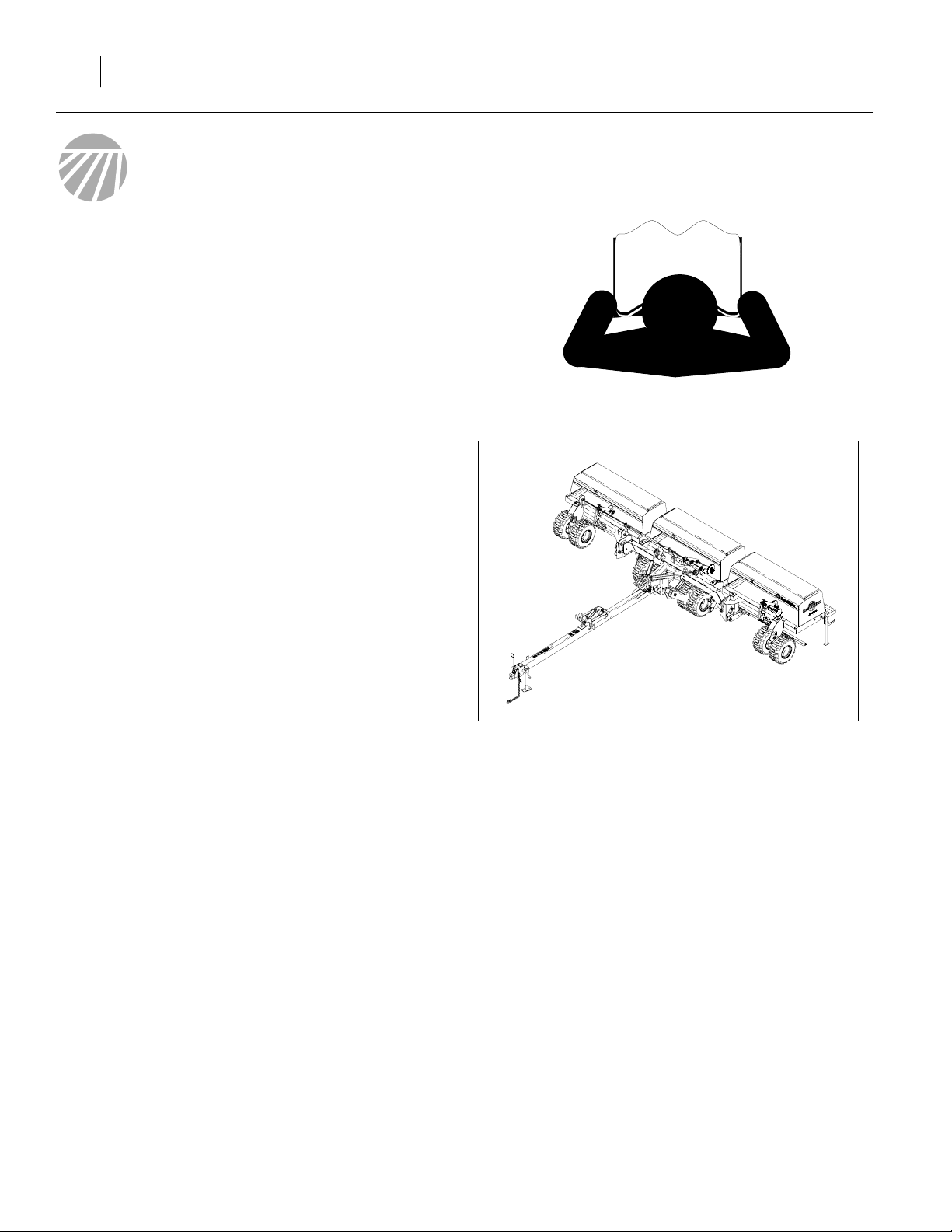
Description of Unit
The 3S-3000HD is a towed seeding implement. This
three section drill has a working width of 30 feet
(12.2m). The drill has straight arm, double disk heavy
duty openers. The opener disks make a seed bed, and
seed tubes mounted between the disks place seed in
the furrow. Press wheels following the opener disks
close the furrow and gauge opener seeding depth. A Thandle on the opener body is for seeding depth adjustments. Seeding rates are adjustable with the seed rate
adjustment handle and sprocket changes.
The 3S-3000HD features active hydraulic down pressure on the opener frames. When used on a tractor
with closed-center hydraulics, constant down pressure
ensures even opener penetration in uneven ground.
Hydraulic down pressure is adjustable at a single
point.
Intended Usage
Use this implement to seed production-agriculture
crops in conventional or minimum tillage applications.
Figure 1
3S-3000HD Drill
15485
Models Covered
3S-3000HD:
3S-3000HD-3610 (10in / 24cm)
3S-3000HD-4875 (7.5in / 19cm)
3S-3000HD-6006 (6in / 15cm)
3S-3000HDF-3610 (10in / 24cm)
3S-3000HDF-4875 (7.5in / 19cm)
3S-3000HDF-6006 (6in / 15cm)
195-068Q 12/09/2009
Page 7
Using This Manual
This manual was written to help you assemble and
prepare the new machine for the customer. This manual includes instructions for assembly and setup. Read
this manual and follow the recommendations for safe,
efficient and proper assembly and setup.
An Operator’s Manual is also provided with the new
machine. Read and understand Important Safety Information and Operating Instructions in the Operator’s
Manual before assembling the machine. As a reference, keep the Operator’s and Parts manuals on hand
while assembling.
Definitions
The following terms are used throughout this manual.
Right-hand and left-hand as used in this manual are
determined by facing the direction the machine will
travel while in use unless otherwise stated.
R
Figure 2
Left/Right Notation
Introduction 5
L
15485
Paragraphs in this format present a crucial point of information related to the current topic.
Read and follow the directions to:
- remain safe,
- avoid serious damage to equipment and
- ensure desired field results.
Note: Paragraphs in this format provide useful informa-
tion related to the current topic.
Assembly and Setup Assistance
To order additional copies of predelivery instructions or
operator’s and parts manuals, write to the address
below. Include model numbers in all correspondence.
If you do not understand any part of this manual or
have other assembly or setup questions, assistance is
available. Contact:
Product Support
Great Plains Mfg. Inc., Service Department
PO Box 5060
Salina, KS 67402-5060
785-823-3276
12/09/2009 195-068Q
Page 8

6 3S-3000HD
Preparation
Step-by-step instructions for assembling the implement
begin in the next section of the manual. Before commencing work, review the Tools Required and PreAssembly Checklist to make sure you have all necessary parts and equipment.
The implement is shipped via flat bed truck. It is the
dealer’s responsibility to unload the new machine.
Unload all equipment before beginning assembly.
Scope The Work
Depending on the shipping route and destination, the
3S-3000HD drill may require only light component
installation (Wide Load), or it may require assembly of
major components (Standard Load).
Do not attempt any assembly work while the implement is on
the truck.
Wide Load Assembly
The drill is shipped substantially assembled, less wing
walkboards, press wheel arms, press wheels, walkboard reflector decals, accessories and some options.
The following items are installed after delivery, in this
approximate order:
• Wing walkboards (2)
• Walkboard fixed step or swing-down ladder
• Wing walkboard decals
• Additional options and accessories not factoryinstalled, such as acremeter, press wheels, markers,
hydraulic kits, shaft monitors and scrapers.
Overview of Work
All fasteners and misc. components are located in their
assembly location, or in bags/cartons inside a drill seed
box.
Assembly
1. Unload truck.
2. Assemble major sections (Legal Load only).
3. Install walkboards, steps/ladders and decals.
4. Install other standard and optional components that
were not factory-installed, but need to be present
prior to first hydraulic operations, such as press
wheels.
Standard “Legal” Load Assembly
The drill is shipped substantially disassembled, to keep
the trailer under 8.5ft wide.
The following items are assembled/installed after delivery, in this approximate order:
• Tongue to mainframe assembly
• Center box to Main frame assembly
• Left hand wing box
• Right hand wing box
• Transfer drive shaft
• Additional options and accessories not factoryinstalled, such as acremeter, press wheels, markers,
hydraulic kits, shaft monitors and scrapers.
Setup
5. Hitch to suitable tractor.
6. Connect hydraulics.
7. Bleed hydraulics.
8. Level drill.
9. Install any other components or options not factory-
installed.
195-068Q 12/09/2009
Page 9

Preparation 7
Tools Required
• Forklift, loader or overhead hoist with a capacity of:
Wide Load unload: 13,500 pounds (6124 kg)
Legal Load unload: 3732 pounds (1693 kg)
Legal Load assemble: 2535 pounds (1150 kg)
• A tractor of sufficient size and horsepower with at
least two remote hydraulic circuits. Refer to “Specifi-
cations and Capacities” in the Operator’s Manual.
• General hand tools
• Jack stands or blocks and safety chain
Note: You will need about 4.5 gallons of hydraulic oil to
refill the tractor hydraulic reservoir after initial
bleeding and cycling of the hydraulic systems.
Pre-Assembly Checklist
1. Read and understand “Important Safety Information” on page 1 before assembling.
2. Have at least two people on hand while assembling.
3. Make sure the assembly area is level and free of
obstructions (preferably an open concrete area).
Allow room for wing unfolding and any markers (See
“Position for Assembly” on page 8).
4. Have all major components accounted for.
5. Have all fasteners and pins shipped with implement.
6. Have a copy of the implement Parts Manual (195068P) on hand. If unsure of proper placement or
use of any part or fastener, refer to the parts manual.
7. Check that all working parts are moving freely, bolts
are tight, and cotter pins are spread.
8. Check that all factory-applied safety labels and
reflectors are correctly located and legible. Replace
if improperly located or damaged. Refer to Safety
Decals, in the “Important Safety Information” section of the implement Operator’s Manual.
Note: Some decals are dealer installed, to prevent
decal damage during disassembled shipment.
9. Inflate tires to recommended pressure as listed on
the “Tire Inflation Chart” on page 38.
10. Tighten wheel bolts as specified on “Torque Values
Chart” on page 39.
If a pre-assembled part or fastener is temporarily removed,
remember where it goes. Keep the parts separated.
12/09/2009 195-068Q
Page 10

8 3S-3000HD
Assembly
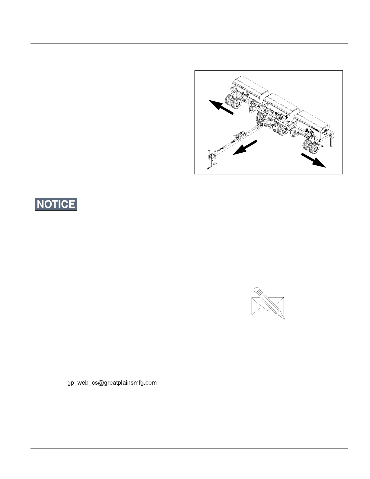
Position for Assembly
1. Unload mainframe (Legal Load) or drill (Wide Load)
from truck and place it in a location that allows for:
• tow away depth:
28 feet (8.5m) plus
length of tractor plus
turning room
• wing unfolding:
16 feet (4.9m) either side of centerline, or
32 feet (9.8m) total span), and
• if markers were ordered:
32 feet (9.8m) either side of centerline, or
64 ft (19.5m) total span.
If the drill was shipped as a Wide Load, skip to “Install
Wing Walkboards and Steps” on page 15.
Assemble Tongue to Mainframe
When space is available on the trailer, the tongue is factory-assembled, in which case skip to “Install Center
Box on Frame” on page 10.
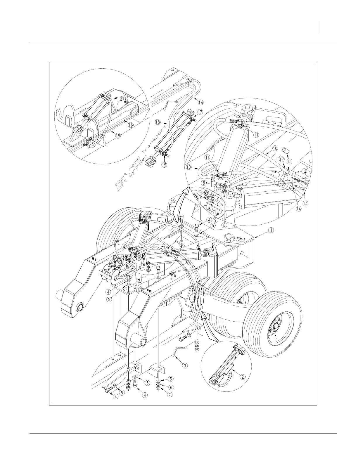
Refer to Figure 3 on page 9
2. Block the mainframe assembly up in the raised
position with the transport cylinders extended and
the cylinder lock channels over the cylinder rods.
3. With the aid of a fork-lift, hoist, or loader, position
the tongue assembly back under the mainframe
assembly and bolt it into place with the twelve
3
1x2
ers and 1in nuts .
1
⁄
in bolts , 1in flat washers , 1in lock wash-
4
6 7
4 5
3
Lightly tighten all 1in bolts before torquing any of
them.
4. Once the tongue is assembled, remove the cylinder
lock channels , completely lower the mainframe
2
assembly and secure it in this position.
5. Route the two long
3
⁄
in hydraulic hoses from the
8
back of the tongue tube along the right side of the
main frame and connect them to the
9
tees on the front of the main frame.
1
2
8
9
⁄
in bulkhead
16
6. Route the two long
back of the tongue to the
1
/
in hoses coming out of the
4
10
9
⁄
in tees on the rod
16
11
and base ends of the right fold cylinder.
The fold circuit hoses run the full length of the
10
tongue.
7. Secure the hoses and with a hose clamp
bracket and
washers .
12 13
14
Use rubber hydraulic hose guards on the
8
5
⁄
x2
16
10
1
/
in bolts and
4
5
⁄
in lock
16
15
1
hydraulic hoses.
8. Route the long
1
/
in hose coming from the base
4
16
end of box lift cylinder at the center of the tongue to
9
the
⁄
in base end tee at the right transport lift
16
17
cylinder on the transport axle.
Route the long
1
/
in hose coming from the rod
4
18
end of box lift cylinder at the center of the tongue to
the
9
⁄
in rod end tee at the right transport lift cyl-
16
19
inder on the transport axle.
/
in
4
195-068Q 12/09/2009
Page 11
Assembly 9
Figure 3
15608
Tongue Installation and Hose Routing
12/09/2009 195-068Q
Page 12
10 3S-3000HD
Install Center Box on Frame
Refer to Figure 4
9. Pin the drill hitch to a tractor with a minimum of 100
horsepower to secure the drill frame for further
assembly.
10. Center the center box frame assembly behind the
1
mainframe and bolt it in place with the eight
7
3
⁄
x2
⁄
in bolts ,
8
4
washers , and
4 5
7
2 3
⁄
in flat washers ,
8
7
⁄
in nuts .
8
7
⁄
in lock
8
Lightly tighten the bolts at this time, but do not
torque them until the box is leveled later in the
assembly process. See “Leveling the Drill” on
page 31.
Figure 4
15609
Mount Center Box
195-068Q 12/09/2009
Page 13
Install Wing Box Frames
Refer to Figure 5
11. Unfold the wing toolbars until they contact the
center box frame.
12. Remove the horizontal tool bar pivot pins from
the wing box frames. Position a wing box frame
pivot to line up with the pivot tube on the wing toolbar.
13. Install the pivot pin from the front (with the taper
pointing back) placing one
6
on each side of the tool bar pivot.
1
/
14. Assemble a 1
ted nut on the back side of the pin.
4
in flat washer , and 1
4
Torque this rear nut to 600 ft-lbs to properly seat the
pin into the taper before proceeding with the assembly. Use the cotter pin hole on the front end of the
pin to prevent rotation while you tighten the rear nut.
15. After torquing to 600 ft-lbs, secure the nut with a
5
1
⁄
x2
/
16
in cotter pin by rotating the slot in the nut
2
to the next available cotter pin hole in the pin.
1
2
2
1
/
in thick thrust washer
4
3
5
1
/
in hex slot-
4
Assembly 11
There are two cross holes so the slot in the nut
should align with a hole with less than
1
⁄
additional
12
rotation of the nut.
16. Install the large hinge washer , the 1
washer , and the 1
3 4
1
/
in slotted nut on the front
4
7
1
/
in flat
4
side of the pin.
17. Torque the front 1
assemble the
1
/
in slotted nut to 400 ft-lbs and
4
5
1
⁄
x2
/
in cotter pin in the next
16
2
5
available cross hole.
Note: Torquing the rear nut (on the tapered end of the
pin) is easiest when the opener frames are lowered. Consider waiting until the hydraulics are
charged and the openers lowered before torquing
the horizontal pin 1
1
/
in nuts. Always torque the
4
rear nuts before drawing up the front nuts.
Figure 5
15610
Wing Box Pivot
12/09/2009 195-068Q
Page 14
12 3S-3000HD
Install Transfer Driveshaft
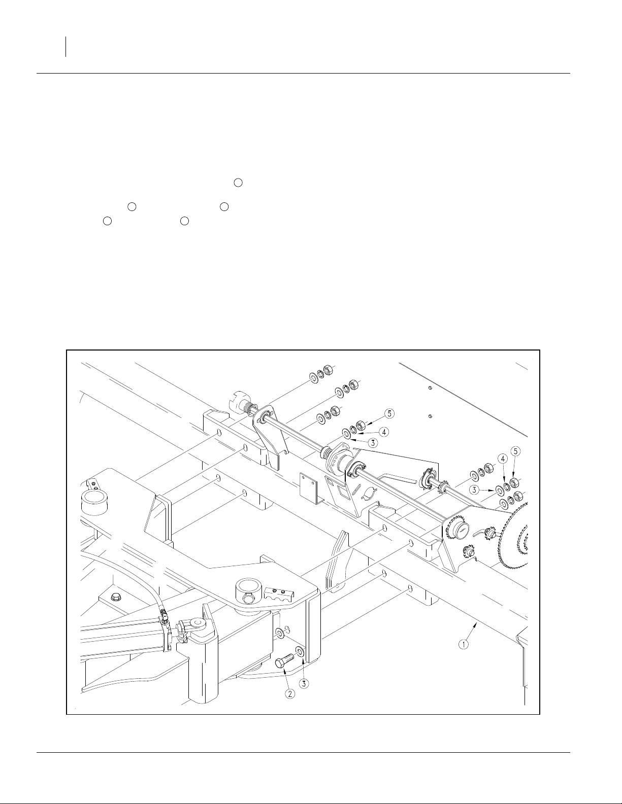
Refer to Figure 6
18. Remove the transfer drive subassembly from the
drill seed box. The transfer drive assembles to the
right side of the drill, and transfers the drive power
to the center box assembly.
19. Assemble the U-joint end of the transfer drive
assembly to the U-joint yoke on the right wing
box. Use
1 2
3
3
⁄
x3
⁄
8
4
3 4
in pin and
3
⁄
x1in cotter pins .
32
20. Clip the shipping wire, and telescope the end of the
drive assembly toward the break away-drive assembly at the center of the drill.
1
21. Engage the jaws of the break-away clutches , and
fasten the bearing bracket to the plate extending
up from the right wing tool bar .
1
Use the two
washer ,
9
1
/
x1
/
in round head bolts ,
2
1
2
/
in lock washers and
2
Note: DO NOT tighten the
6
7
10 11
1
/
in bolts yet.
2
1
/
8
5
1
8
/
in flat
2
in nuts .
2
The box lead must be adjusted before the drive
assembly can be adjusted.
Figure 6
15611
Transfer Drive Shaft
195-068Q 12/09/2009
Page 15
Connect Opener Lift Hoses
Refer to Figure 8 on page 14
22. Connect the
3
⁄
in hydraulic hoses coming from
8
the back side of the wing pressure control valve to
the base end tees on the inner opener lift cylin-
3
der of each wing frame.
2
This is the hose which should extend beyond the
wing tool bar hose holder by 45in (1.1m) as
4
assembled from the factory.
23. Connect the
3
⁄
in hydraulic hoses coming from
8
the bottom of the wing pressure control valve, to
the tee at the jumper hose coming from the
6 7
rod end of the inner opener lift cylinder of each
wing frame.
1
5
3
Assembly 13
This is the hose which should extend beyond the
wing tool bar hose holder by 35in (89cm) as
4
assembled from the factory.
24. Disconnect the
where they tee together at the back of the main-
3
⁄
in hydraulic hoses and
8
8
1 5
frame and reroute them through the hose guide
cutouts and through the plastic tie downs on the
9
center box frame.
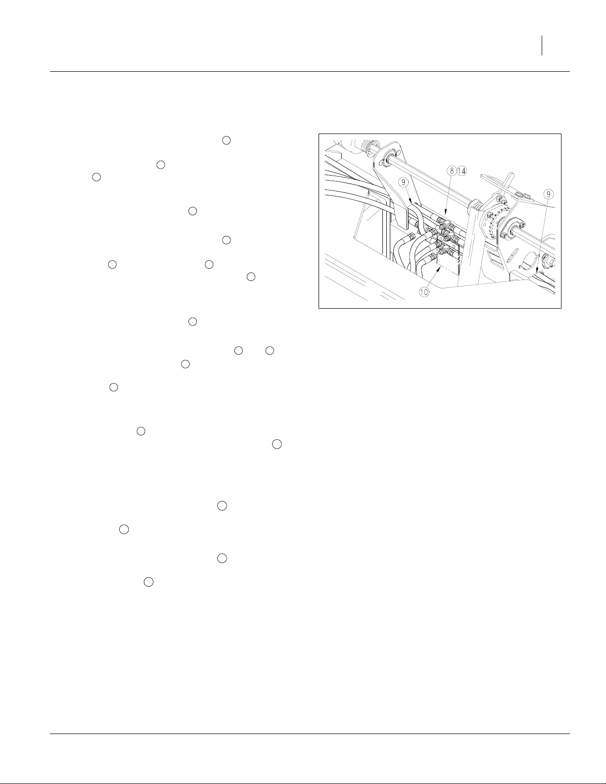
Refer to Figure 7
25. Place all tees which rest on the center box
8
frame on the right side of the formed bracket
welded to the center of the frame.
This keeps them out of the clutch linkage which is
left of center.
26. Connect the
3
⁄
in hydraulic hose coming from
8
11
the back side of the center pressure control valve
to the tee which branches to the base ends of
12
the center two opener lift cylinders.
27. Connect the
3
⁄
in hydraulic hose coming from
8
13
the bottom side of the center pressure control
valve to the tee which branches to the rod ends
14
of the center two opener lift cylinders.
28. Tighten the plastic tie down straps to keep the
hoses out of the drives.
Figure 7
15656
Opener Lift Tees
10
12/09/2009 195-068Q
Page 16

14 3S-3000HD
Figure 8
15666
Opener Lift Hydraulic Diagram
195-068Q 12/09/2009
Page 17

Install Wing Walkboards and Steps
There are two walkboards, one on the back of each
wing seed box. The walkboards themselves are identical for each section. The way they install varies by section. The center walkboard is factory-installed.
Bolts for walkboards are shipped in a bag in one of the
drill boxes.
If the drill has swing-down ladders, the wing walkboard
installation is identical at the outside ends as well.
If the drill has single steps, they are mounted as part of
the walkboard installation, and require longer bolts.
Walkboards with Single Steps
Refer to Figure 9
1. Select one walkboard , and four sets of
1
1
⁄
x1
⁄
inch bolts , lock washers and hex nuts .
2
4
2. Using the top bolt holes on each end, temporarily
bolt each wing walkboard to box support chan-
2
nels .
3. Skip to “Install Fixed Walkboard Steps” on page
17.
1
3 4
1
Assembly 15
3
1
4
2
Figure 9
Wing Walkboards, Inner End
18810
Walkboards with Swing-Down Ladders
Refer to Figure 9
1
1. Select eight sets of
ers and hex nuts .
2. Bolt each wing walkboard to box support chan-
2
nels .
1
⁄
x1
⁄
inch bolts , lock wash-
2
4
4
1
3
12/09/2009 195-068Q
Page 18

16 3S-3000HD
Install Swing-Down Ladders
If the drill includes swing-down ladders, they are
installed after the walkboards are installed.
Refer to Figure 10 or Figure 11
Where to place the top ladder mount depends on
whether the drill has the Small Seeds option. Install with
reference to the appropriate Figure for the drill.
Install Swing-Down Ladder Mounts
Refer to Figure 10
Top mount weldments are provided in left- and rightside versions and are not interchangeable. All other
parts may be used on either end. Starting with the left
wing:
1
2
1
7
3
1. Select the left wing top mount weldment .
2. Select four
bolts .
7
⁄
16
2
3. Position the top mount over the four walkboard
3
holes second from the left rear corner of the
-14x1
3
⁄
in round head shank neck
4
1
1
walkboard.
4. Insert the four bolts to loosely hold the top mount
in place on the walkboard .
5. Select a bottom mount plate and four sets of:
7
5
⁄
plated washers, and
16
7
6
⁄
-14 nuts.
16
6. Position the bottom plate under the walkboard
and inside the top mount . Loosely hold it in place
with the washers and nuts .
2
3
4
4 3
1
5 6
7. Select two sets of:
3
7
⁄
-16x1in hex head cap screws
8
3
8
⁄
in lock washer
8
3
9
⁄
-16 flange nut
8
8. Insert the screws through the side holes in both
the top mount and bottom plate , and secure
with lock washers and flange nuts .
9. Tighten the four
7
1 4
8 9
7
⁄
in bolts securing the top mount
16
to the bottom plate.
10. Repeat for right wing section.
4
9
8
5
6
Figure 10
Mount w/o Small Seeds
27013
2
1
7
3
4
9
8
5
6
Figure 11
Small Seeds Mounting
195-068Q 12/09/2009
27055
Page 19

Install Ladders
1. Lay the ladder on the walkboard with the swing
holes up and near the top mount lug holes . Align
1
2
the holes in the ladder in between the holes in the
lugs.
2. Select two sets of:
3
3
⁄
1
4
⁄
3
5
⁄
3. Insert a screw through a washer and then
through the ladder side plate and lug . Secure
with lock nut .
1
-16x1
⁄
8
in washer
2
-16 flange nut
8
inch hex head cap screws
4
5
3 4
1 2
4. Repeat for right wing section.
5. Skip to “Install Reflectors and Decals” on page
18.
Install Fixed Walkboard Steps
Assembly 17
1
2
5
4
3
Figure 12
Swing-Down Ladder
27013
Refer to Figure 13
1
1. Use the
4 1 6
nuts to bolt a walkboard and step on out-
3
⁄
x1
⁄
inch bolts , lock washers and hex
2
4
5
side ends of a wing.
Note: The steps are not interchangeable. Bolt steps
6
so that steps jog away from the end panel and extend back.
2. Repeat for other wing.
2
4
1
5
6
Figure 13
Walkboard Step & Outer End
18810
12/09/2009 195-068Q
Page 20

18 3S-3000HD
Install Reflectors and Decals
To prevent scuffing in shipment, walkboard decals are
shipped in a bag in one of the drill boxes, and are
applied after walkboard installation.
The precise location of the outside wing decals depends
on whether a fixed step or swing-down ladder is
installed.
To install new reflectors and decals:
• Clean and dry the area where the reflector or decal is
to be placed.
• Peel backing from reflector or decal. Press firmly on
surface, being careful not to cause air bubbles under
reflector or decal.
Wing Walkboard Inner Decals
Refer to Figure 14
Starting with the left walkboard, inboard end:
1. Place one 838-266C Red decal on the outside
end. Align the outside end of the decal with the
walkboard corner. This decal marks the left and
right extents of the drill in transport (folded).
2. Place one 838-265C Amber decal on the rear
face of the walkboard. Align the rear end of the
decal with the inboard walkboard corner.
3. Repeat for right wing walkboard.
1
2
Wing Fixed Step Decals
If the drill is equipped with a swing-down ladder, skip
these steps and use the instructions at “Wing Swing-
Down Ladder Decals” on page 19.
Refer to Figure 15
Starting on the left wing walkboard:
1. Place the 838-102C Danger Falling Hazard decal
on the outside end of the walkboard, just aft of the
step’s vertical riser, where it is visible to climbers.
2. Place one 838-265C Amber decal on the outside
(step) end of the walkboard . Align the rear end of
the decal with the walkboard corner.
3. Place one 838-265C Amber decal on the rear face
of the walkboard, step end . Align the rear end of
the decal with the walkboard corner.
4. Repeat for right wing section walkboard.
2
3
2
Figure 14
Wing Walkboard Inner End
1
27022
1
1
3
2
Figure 15
Fixed Step Ladder Decals
27017
195-068Q 12/09/2009
Page 21

5. Skip to “Other Assembly Items” on page 19.
Wing Swing-Down Ladder Decals
Assembly 19
Refer to Figure 16
Starting on the left wing walkboard:
1. Place the 838-102C Danger Falling Hazard decal
forward of and near the top of the ladder, where it is
visible to climbers.
2. Place one 838-265C Amber decal on the outside of
the ladder mount, between the ladder side plates
(so it won’t be damaged by ladder operation).
3. Place one 838-265C Amber decal on the rear and
corner of the ladder mount. This decal is slightly
3
longer than that side of the mount. Wrap the excess
around the corner.
4. Repeat for right wing section walkboard ladder.
Other Assembly Items
There are a few additional standard components, and
several possible optional items, that are not factory
installed. Some of these, which follow in this chapter,
need to be installed prior to first hydraulic hookup. Others are installed after hookup, bleeding and leveling.
See “Install Final Accessories” on page 36.
1
1
2
2
3
Figure 16
Swing-Down Ladder Decals
27016
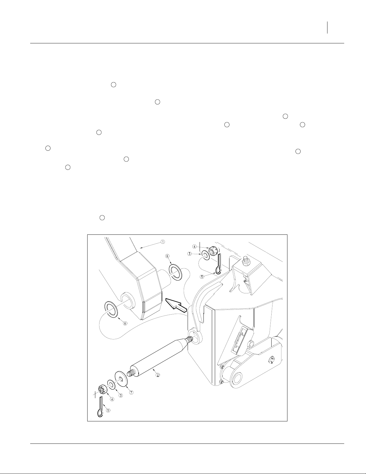
Install Press Wheels
Refer to Figure 17
1
1. Remove
2
nut from each opener body.
3
⁄
x3
⁄
inch flange bolt and flange lock
2
4
2. Leave pivot bushing components in place and
bolt press wheel arm to opener with
flange bolt and lock nut . Repeat for all open-
1 2
4
ers.
3. Remove
4 6
and use bolts to assemble press wheels to
5
⁄
inch bolt from each press wheel arm
8
5
press wheel arms.
1
3
1
3
⁄
x3
⁄
inch
2
4
1
6
5
3
2
4
Figure 17
Press Wheel Assembly
24432
12/09/2009 195-068Q
Page 22

20 3S-3000HD
Two Outlet Kit
If the Two-Outlet Hydraulic Kit was ordered, install it
now (before the markers, as this kit contains items
needed when both 2-outlet and markers are installed).
Installation instructions are provided in a separate
manual with the Two-Outlet kit.
Markers
Markers are not factory-installed, due to vertical clearance requirements during shipment. An installation
manual is provided, but does not include details for
installation where a Two-Outlet Kit is also present. If a
Two-Outlet kit is installed, observe these tips:
• The Marker/Fold valve mounts on the second valve
bracket.
• Use the longer bolts in the Two-Outlet kit to stack
the hose clamps. Place the clamp hold-down on the
top clamp.
• For consistency of operation, be sure to plumb the
Fold circuit to the forward ports of the Marker/Fold
valve, and plumb the Marker circuits to the rear.
Handle forward is then Transport operations (Fold),
and handle back is then Field operations (Marker).
Consult the drill Operator’s manual for setting initial
marker extension length, and the latest information on
chain length and stop bolt adjustment.
Figure 18
Two-Outlet Selector
Figure 19
Marker
27020
26493
195-068Q 12/09/2009
Page 23

Open Center Conversion
If the drill was shipped with an Open Center kit, it is not
factory-installed. Install it now. An installation manual is
provided.
G
P
1
2
R
T
3
BASE END, CENTER OPENERS
ROD END CENTER OPENERS
G
P
2
R
T
3
ROD END WING OPENERS
1
BASE END WING OPENERS
Assembly 21
FILTER
LOWER
TO TRAC TOR
RAISE
3
Point Row Option
If the Point Row Option was ordered with the drill, the
hydraulics and drill electrical lead are factory-installed.
If the customer’s primary tractor is available, install the
control module in the tractor cable and make the electrical connection. Consult the Point Row installation manual provided.
If the primary tractor is not available, temporarily connect the control module so that openers can be operated during Setup.
Post Assembly Checklist
• Check that all working parts are moving freely, bolts
are tight, and cotter pins are spread.
• Check for proper tension and alignment on all drive
chains.
• Check that all safety decals and reflectors are located
correctly and are legible. Replace if improperly
located or damaged. Refer to “Safety Decals” in the
Operator’s manual.
• Inflate tires to recommended pressures as listed on
the “Tire Inflation Chart” on page 38. Tighten wheel
bolts as specified on “Torque Values Chart” on page
39.
Figure 20
Open Center Conversion
Figure 21
Point-Row Connector
18750
26469
12/09/2009 195-068Q
Page 24

22 3S-3000HD
Setup
The assembly steps of the preceding chapter must be
completed prior to setup.
Setup steps consist of:
1. Hitch to suitable tractor.
2. Connect hydraulics.
3. Bleed hydraulics.
4. Level drill.
5. Install any options not factory-installed.
Hitching
You may be severely injured or killed by being crushed
between the tractor and drill. Do not stand or place any part
of your body between machines being hitched. Stop tractor
engine and set park brake before installing hitch pins.
This drill can have positive and negative tongue weight,
which can work the hitch pin loose during transport. To avoid
serious injury or death due to a road accident, always use a
clevis hitch or clevis drawbar with a locking-style hitch pin.
Choose a drill-hitch option that is compatible with your
tractor drawbar.
Refer to Figure 22
The 3S-3000HD has three hitch options:
• a clevis hitch,
• a small-hole, single-strap hitch or;
• a large-hole, single-strap hitch.
Use the clevis hitch with tractors that have single-tang
drawbars. Use the single-strap hitch for tractors with clevis drawbars. Always use a locking-style hitch pin sized
to match the holes in the hitch and drawbar.
Figure 22
Hitch Options
27006
195-068Q 12/09/2009
Page 25

Refer to Figure 23 and Figure 24
To adjust the drill hitch to match your tractor-drawbar
height, mount tongue jack on side of tongue. Use jack to
raise drill tongue so lowest hitch hole is 18 inches
(45.7cm) above ground level with drill lowered to FIELD
position.
Refer to Figure 24
Bolt drill hitch onto drill tongue to match your tractordrawbar height. You can turn the hitch over for a total of
six different hitch heights. Always have two (2) bolts in
two holes of both tongue and hitch.
Note: When hitching drill to a different tractor, checkfor a
difference in drawbar heights. If heights are different, readjust hitch height accordingly.
Securely attach safety chain to an anchor on a tractor
capable of pulling the drill.
Figure 23
Jack in Lifting Location
Setup 23
15564
32.0in
81.3cm
29.0in
73.7cm
26.0in
66.0cm
21.5in
54.6cm
Figure 24
Heights for Various Hitch Positions - Correct Tongue Height
Refer to Figure 25
Use crank to raise jack foot. Remove pin and jack. Store
jack on top of tongue.
18.5in
47.0cm
15.5in
39.4cm
45.7cm
Figure 25
Jack in Storage Location
18.0in
15623
15563
12/09/2009 195-068Q
Page 26

24 3S-3000HD
Electrical Connections
Refer to Figure 26
Plug drill electrical lead into tractor seven-pin connector.
Refer to Figure 27
If the drill is equipped with the point row option, mate the
connector for the cab control.
Figure 26
Lighting Connector
Figure 27
Point-Row Connector
26467
26469
195-068Q 12/09/2009
Page 27

Hydraulic Hose Hookup
Only trained personnel should work on system hydraulics!
Escaping fluid under pressure can have sufficient pressure to
penetrate the skin, causing serious injury. Avoid the hazard by
relieving pressure before disconnecting hydraulic lines. Use a
piece of paper or cardboard, NOT BODY PARTS, to check for
leaks. Wear protective gloves and safety glasses or goggles
when working with hydraulic systems. If an accident occurs,
see a doctor immediately. Any fluid injected into the skin must
be surgically removed within a few hours or gangrene will
result.
Refer to Figure 28
To distinguish hoses on the same hydraulic circuit,
refer to plastic hose label. The hose under an
extended-cylinder symbol feeds a cylinder base end.
The hose under a retracted-cylinder symbol feeds a
cylinder rod end.
Great Plains hydraulic hoses are color coded to help
you hookup hoses to your tractor outlets.Hoses that go
to the same remote valve are marked with the same
color.
Setup 25
Color Hydraulic Function
Red Opener Lift Cylinders
Blue Transport Lift Cylinders
White Fold Cylinders
Orange Marker Cylinders
1. Connect opener-lift hoses to circuit designated for
hydraulic-motor control.
2. Connect transport-lift hoses to tractor remote
valve.
3. Connect fold hoses to tractor remote valve.
4. Connect marker hoses to tractor remote valve.
Note: If your tractor has only two remote valves, you
must install a double-selector valve to combine
the transport-lift and opener-lift circuits. See
“Two Outlet Kit” on page 20.
Figure 28
Plastic Hose Label
To run drill on tractors with open-center hydraulics or on
tractors with fixed-displacement hydraulic pumps, you must
install a Great Plains kit, part number 194-143A.
817-348c
17641
12/09/2009 195-068Q
Page 28

26 3S-3000HD
Bleeding Hydraulics
To function properly, the hydraulics must be free of air. If
hydraulics have not been bled, they will operate with
jerky, uneven motions and could cause wings to drop
rapidly during folding or unfolding. If hydraulics were not
bled during initial implement setup or if you replace a
part in hydraulic system during the life of the drill, complete the following procedures.
Escaping fluid under pressure can penetrate the skin causing
serious injury. Avoid the hazard by relieving pressure before
disconnecting hydraulic lines. Use a piece of paper or cardboard, NOT BODY PARTS, to check for suspected leaks. Wear
protective gloves and safety glasses or goggles when working
with hydraulic systems. If an accident occurs, see a doctor
immediately. Any fluid injected into the skin must be surgically removed within a few hours or gangrene may result.
Raising openers on unfolded, unhitched drill will cause drill
tongue to rise suddenly, which could cause serious injury or
death. Be certain that drill is hitched securely to your tractor
drawbar and the safety chain is securely attached to tractor
before raising openers and unfolding drill.
Bleed only at:
JIC (Joint Industry Conference, 37° flare) or
NPT (National Pipe Thread, tapered thread) fittings.
Never bleed at:
ORB (O-Ring Boss) or
QD (Quick Disconnect) fittings.
Check hydraulic fluid level in tractor reservoir and fill to
proper level. Add fluid to system as needed.
Note: System capacity for entire drill is about
1
4
⁄
U.S. gallons
2
(17 liters).
195-068Q 12/09/2009
Page 29

Bleeding Fold Hydraulics
Refer to Figure 29
1. Review warnings, bleeding notes and system infor-
mation on page 26.
2. With drill unfolded and fold cylinders completely
extended, disconnect rod end pins and swing the
cylinders so they will not contact anything when
extended.
3. Loosen rod end hose JIC fitting at elbow on right
fold cylinder.
1
Setup 27
5. With cylinders completely retracted, loosen base
end hose JIC fitting at elbow on right fold cylin-
der.
6. Slowly supply oil to base end of fold cylinders (line
4
) until oil appears at loosened hose fitting. Tighten
base end hose fitting and cycle fold cylinders in and
out several times.
7. Re-pin cylinder rod clevis.
2
4. Slowly supply oil to rod end of fold cylinders (line )
until oil appears at loosened hose fitting. Tighten fitting and completely retract fold cylinders.
3
4
3
1
2
Figure 29
Bleeding Fold Hydraulics
12/09/2009 195-068Q
15644
Page 30

28 3S-3000HD
Bleeding Opener Lift Hydraulics
Refer to Figure 30
1. Review warnings, bleeding notes and system information on page 26.
2. Make sure opener frames are locked up in ROAD
position. See “Opener Lock Up” in Operator’s Manual.
3. Turn knob on both pressure-control valves completely counterclockwise, then turn valves clockwise
far enough to build up 1000 psi (about three turns).
4. Turn knob on bypass valve completely clockwise for
no oil flow.
5. Loosen six hose-end JIC fittings at three locations
on the opener-lift circuit:
• both JIC fittings on the two
feeding the center opener lift cylinders,
• the JIC fittings on the two
feeding the center opener lift cylinders, and;
• the end where these center two hoses tee at the
middle of the center box frame.
3
⁄
in opener lift hoses
8
3
⁄
in opener lift hoses
8
6. Slowly supply oil to top side of pressure-control
valves until oil begins to appear at a loosened hose
fitting. As oil begins to appear at a fitting, tighten
that fitting.
7. Slowly supply oil to bottom side of pressure-control
valves until oil begins to appear at remaining loosened hose fitting. As oil begins to appear at the fitting, tighten fitting. Continue to supply oil to bottom
side of pressure-control valves until all openers are
raised completely.
8. Move opener transport locks to FIELD position and
cycle openers up and down ten times. Each time
you lower openers, hold tractor remote lever until
opener circuit builds up to pressure set at control
valves.
9. After cycling openers, return opener transport locks
to ROAD position, and lock openers up.
Figure 30
15644
Bleeding Opener Lift Hydraulics
195-068Q 12/09/2009
Page 31

Bleeding Transport Lift Hydraulics
Refer to Figure 31
1. Start with the transport axle in the lowered (field)
position, and the box lift cylinder (at the middle of
the tongue) completely retracted. Loosen the base
end hose fitting at the elbow on the left transport lift
cylinder and the base end hose fitting on the box lift
cylinder at the middle of the tongue.
2. Slowly supply oil to the base end of the transport lift
cylinders until oil appears at the loosened hose fittings. Oil may not appear at both location at same
time. As oil begins to appear at a fitting, tighten that
fitting and proceed until both fittings have been
tightened. Completely extend the transport lift cylinders and IMMEDIATELY lock the cylinders up by
flipping up the cylinder lock channels on both transport lift cylinders and the box lift cylinder at the middle of the tongue.
Setup 29
NEVER CRAWL UNDER THE DRILL IN THE RAISED POSITON WITHOUT THE CYLINDER LOCK CHANNELS IN
PLACE.
3. When the cylinder lock channels are in place,
loosen the rod end hose fitting at the elbow on the
left transport lift cylinder and the rod end hose fitting
on the box lift cylinder at the middle of the tongue.
4. Slowly supply oil to the rod end of the transport lift
cylinders until oil appears at the loosened hose fittings. As oil begins to appear at a fitting, tighten that
fitting and proceed until both fittings have been
tightened.
5. Extend the transport lift cylinders, and remove the
cylinder lock channels. Completely cycle the transport lift hydraulics several times.
Figure 31
15645
Bleeding Transport Lift Hydraulics
12/09/2009 195-068Q
Page 32

30 3S-3000HD
Bleeding Marker Hydraulics
You may be injured if hit by a folding or unfolding marker.
Markers may fall quickly and unexpectedly if the hydraulics
fail. Never allow anyone near the drill when folding or
unfolding markers.
1. Review warnings, bleeding notes and system information on page 26.
Refer to Figure 32
2. With markers unfolded in field position, crack
hydraulic-hose JIC fittings at base and rod ends
of each marker cylinder.
3. With tractor at idle speed, activate tractor hydraulic
valve forward until oil appears at a fitting. When oil
begins to seep out around a fitting, tighten that fitting. Reverse the tractor hydraulic valve until oil
appears at opposite hose fitting. Tighten that fitting.
4. If you have dual markers, activate tractor hydraulic
valve forward again until oil seeps out around a fitting on the other marker cylinder. Tighten that fitting.
Reverse tractor hydraulic valve until oil seeps out
around remaining hose fitting and tighten it.
5. Fold and unfold markers slowly to work out all air.
Note: Use caution when folding and unfolding markers
for the first time, checking for pinching and kinking of hoses.
1
Figure 32
Bleeding Marker Hydraulics
18942
195-068Q 12/09/2009
Page 33

Leveling the Drill
To perform leveling, the drill must be hitched to a tractor,
with at least the hydraulics connected.
Raising openers on unfolded, unhitched drill will cause drill
tongue to rise suddenly, which could cause serious injury or
death. Be certain that drill is hitched securely to your tractor
drawbar and the safety chain is securely attached to tractor
before raising openers and unfolding drill.
Center Box Frame Leveling
1. Park the drill on a clean level surface.
2. Raise the openers and lock them up. See “Raising
and Lowering Openers” in Operator’s Manual for
opener lift and lock instructions.
Refer to Figure 33
(bolts, nut and washers shown removed for clarity loosen, but do not remove them).
3. Loosen the eight center box mount bolts, four bolts
on each side of tongue and slide center box frame
sideways until it is centered with mainframe and
transport axle.
Setup 31
Refer to Figure 34 and Figure 33
4. Measure the height of center box opener frame
pivots from the level surface and raise low end
2
of box frame up until both opener frame pivots
measure the same distance from the ground.
5. Tighten the
7
⁄
-9in box mount bolts to torque
8
1
specified in “Torque Values Chart” on page 39.
Opener Frames Level
Check that opener frames are level across drill. When
fully raised, top of opener mounts should clear bottom
of drill frame tube by at least
1
⁄
in (1.3cm).
2
1
Figure 33
Center Box Mount Bolts
2
Figure 34
Opener Frame Pivot Height
26498
18874
12/09/2009 195-068Q
Page 34

32 3S-3000HD
Wing Box Alignment
1. Place a block ahead of the wing gauge wheels.
Refer to Figure 35
2. Pull forward against blocks to rock wing frames
back. Pull forward until stop bolts are firmly
against toolbars.
Refer to Figure 36
3. Check for proper alignment by running a string line
4
across back of drill toward outer ends of wings.
Make sure string is parallel to center box (both
measurements equal).
5
4. For proper alignment, outside ends of boxes
should be about 1in to 1
of inside ends .
7
1
⁄
in (2.5 to 3.2cm) ahead
4
5. To adjust box alignment, shorten or lengthen stop
3
bolts to change the contact point with the toolbars. Loosen jam nut and thread stop bolt in or
out. Adjust stop bolts in or out until outside ends of
boxes are 1in to 1
1
⁄
in (2.5 to 3.2cm) ahead of
4
inside ends.
6. Tighten jam nut.
3
6
3
Figure 35
Stop Bolt Location
18988
4
6
7
5 5
7 6
Figure 36
4
15654
Wing Box Alignment Measurement
195-068Q 12/09/2009
Page 35

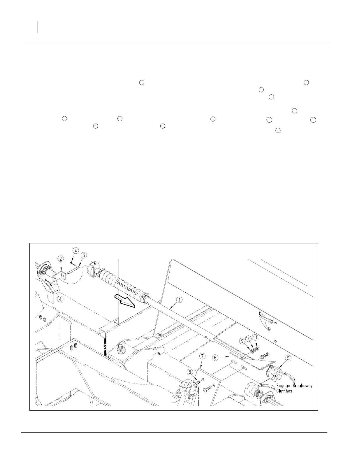
Align Transfer Drive Shaft
Refer to Figure 37 and Figure 38
After wing boxes are properly aligned, the transfer drive
shaft must be aligned so the pair of break-away jaws
are fully engaged and are concentric. The
shafts holding the clutch jaws should not contact each
2
other when wing boxes are properly aligned and back
against their stops.
1. Place a 4x4in (10x10cm) or similar sized block
ahead of the wing gauge wheels and pull forward or
push wing box frames back until the tool bar is firmly
against tool bar stop bolts on the center box frame.
2. To align the clutch jaws vertically, loosen the two
5
⁄
inch bolts securing the bearing flangettes .
8
3 4
Slide the flangettes in the desired direction. Tighten
bolts.
7
⁄
in hex drive
8
Setup 33
4
1
3
1
2
Figure 37
Transfer Drive Jaws
18955
3
4
Figure 38
Transfer Drive Shaft Front-Back Adjustment
15620
12/09/2009 195-068Q
Page 36

34 3S-3000HD
Refer to Figure 39 and Figure 40
3. To align the clutch jaws vertically, loosen the two
5
⁄
inch bolts at the bottom of the breakaway
16
clutch bracket , and adjust the bracket as needed.
5
6
1
4. To adjust clutch jaws for full jaw contact, loosen the
5
two
⁄
inch carriage bolts and slide breakaway
16
clutch bracket until jaws on the fixed half of clutch
9
8
make full contact with jaws on spring loaded half of
clutch without compressing clutch spring.
Note: The two
(3.2mm) gap between them when the clutch
7
⁄
inch hex shafts should have
8
2
7
1
⁄
inch
8
jaws have full contact.
7
1
7
2
Figure 39
18955
Transfer Drive Shaft Gap
7
6
9
8
7
5
Figure 40
15621
Transfer Drive Shaft Vertical and Left-Right Adjustment
195-068Q 12/09/2009
Page 37

Toolbar Height
Refer to Figure 41 and Figure 42
Toolbar height above ground level is factory set
and normally does not require adjustment. If you tear
down the drill for repair, or if the tool bar is visibly not
level, spacer washers on vertical pivot pins allow for a
small amount of tool bar-height adjustment.
To check tool bar height, park drill on a level surface,
and check for correct tire inflation. Measure from ground
to horizontal pivot pin . If dimension on either side of
drill varies more than
height.
1 2
3
1
1
⁄
inch (6.4mm), adjust tool bar
4
Setup 35
1
2
To adjust tool bar height, reposition spacer washers .
3
First lower openers and set enough opener down pressure to help balance frame. Raise tool bar by removing
spacer washers from top of the vertical pivot and placing them on bottom side of pivot. Lower tool bar by
removing spacer washers from bottom of vertical pivot
and placing them on top of pivot.
Figure 41
15616
Toolbar Height
3
Figure 42
15617
Toolbar Height
12/09/2009 195-068Q
Page 38

36 3S-3000HD
Opener-Frame Clearance
Refer to Figure 43
When fully raised, top of opener mounts should clear
bottom of drill frame tube by at least
To adjust opener frames so all openers have the same
clearance, loosen jam nut on opener lift cylinders and
2
turn adjustment nut. When openers are at the correct
height, retighten jam nut. Repeat at each opener lift cylinder if necessary.
1
1
⁄
inch (12.7mm).
2
2
1
Install Final Accessories
Acremeter Installation
Refer to Figure 44
The acremeter is supplied from the factory in a separate carton, to minimize risk of shipping damage. It is
installed on the left end of the center main drive shaft.
Screw the threaded end of the meter into the
tapped hole in the left end of center main drive shaft.
Tighten the threaded end only enough to prevent it from
working loose from normal vibration. In use, there is no
torque or tension that might tend to unscrew it.
The acremeter counts shaft rotations whenever the
shaft is rotating - normally this is only with the drill
unfolded, the opener sub-frame lowered, and the drill in
motion. The meter is geared to display rotations as
acres, when using factory-specified tires and inflations.
Tally field acres by noting the meter reading prior to, and
after planting. Subtract the starting from the ending
readings.
1
1
⁄
-20
2
2
Figure 43
Opener Frame Clearance
2
1
Figure 44
Acremeter Installation
18853
27000
195-068Q 12/09/2009
Page 39

Shaft Monitor
Refer to Figure 45
If the drill was ordered with the optional shaft monitor,
install the sensors and leads per the included installation manual.
If the primary tractor is available, also install the display
console in the cab.
Setup 37
Point Row Controller
If the drill was ordered with the Point Row option, the
solenoid valves, hydraulic lines and control leads were
installed on the drill at the factory.
If the primary tractor is available, also install the display console in the cab.
Scraper Installation
1. Remove one or both disk blades to gain safe access
to the mount. Note the position of bushings and
spacers for correct re-assembly.
Figure 45
Shaft Monitor
18943
26468
22962
Refer to Figure 46
2. Position the inside scraper mount to the rear of
the seed firmer mount on the opener weldment.
Secure it with two HHCS
2
3
⁄
-16x1in hex head bolts,
8
lock washers and nuts. Insert the bolts from the
front.
3. Position the scraper blade below and behind the
inside scraper mount , with the notch on top to
3
1
1
3
2
machine right.
Secure it loosely with one RHSNB
3
⁄
-16x1 round
8
1
head square neck bolt, flat washer, lock washer and
nut.
4. Re-mount the removed disk blade.
12/09/2009 195-068Q
Figure 46
Scraper Installation
26460
Page 40

38 3S-3000HD
Appendix
Specifications and Capacities
3S-3000HD-6006 3S-3000HD-4875 3S-3000HD-3610
Row Count
Row Spacing
Main Seed Box Capacity
Tractor Requirements
Weight, standard HD model
Weight, standard HDF model
Down-Force per Row
Opener Travel
Hydraulic Circuits
Hitch Load
Transport Width
Operating Width
Swath
Height
Length
Tire Sizes
78 63 48
6 in (15.2 cm) 7.5 in (19.1 cm) 10 in (25.4 cm)
92.7 bushels (3267 liters)
125 hp minimum
12447 lbs (5646 kg) 12425 lbs (5636 kg) 12409 lbs (5629 kg)
13496 lbs (6123 kg) 13454 lbs (6102 kg) 13416 lbs (6085 kg)
130-207 lbs
(59-94 kg)
3 circuits required, load-sensitive or closed-center 15 to 30 gpm at 2300 psi
Optional kits are available for two-circuit, and open center.
3700 lbs (1678 kg) folded with seed loaded
Caution: negative tongue weight when raised and unfolded
365 in
(9.271m)
27 feet 7 inches (8.4 meters)
Gauge Wheels: 265/70B16.5 NHS Skid Steer
Transport: 395/55B16.5 NHS Skid Steer
135-280 lbs
(61-127 kg)
8in (20cm)
15 feet (4.6 meters)
30 feet (9.1 meters)
362 in
(9.195m)
7 feet 4 inches (224 cm)
144-373 lbs
(65-169 kg)
360 in
(9.144m)
195-068Q 12/09/2009
Page 41

Torque Values Chart
Appendix 39
Bolt
Size
in-tpi
1
⁄4-20
1
⁄4-28
5
⁄16-18
5
⁄16-24
3
⁄8-16
3
⁄8-24
7
⁄16-14
7
⁄16-20
1
⁄2-13
1
⁄2-20
9
⁄16-12
9
⁄16-18
5
⁄8-11
5
⁄8-18
3
⁄4-10
3
⁄4-16
7
⁄8-9
7
⁄8-14
1-8
1-12
11⁄8-7
11⁄8-12
11⁄4-7
11⁄4-12
13⁄8-6
13⁄8-12
11⁄2-6
11⁄2-12
Bolt Head Identification
Bolt Head Identification
Bolt
Size
Grade 2 Grade 5 Grade 8 Class 5.8 Class 8.8 Class 10.9
1
N-m2ft-lb
7.4 5.6 11 8 16 12
8.5 6 13 10 18 14
15 11 24 17 33 25
17 13 26 19 37 27
27 20 42 31 59 44
31 22 47 35 67 49
43 32 67 49 95 70
49 36 75 55 105 78
66 49 105 76 145 105
75 55 115 85 165 120
95 70 150 110 210 155
105 79 165 120 235 170
130 97 205 150 285 210
150 110 230 170 325 240
235 170 360 265 510 375
260 190 405 295 570 420
225 165 585 430 820 605
250 185 640 475 905 670
340 250 875 645 1230 910
370 275 955 705 1350 995
480 355 1080 795 1750 1290
540 395 1210 890 1960 1440
680 500 1520 1120 2460 1820
750 555 1680 1240 2730 2010
890 655 1990 1470 3230 2380
1010 745 2270 1670 3680 2710
1180 870 2640 1950 4290 3160
1330 980 2970 2190 4820 3560
Torque tolerance + 0%, -15% of torquing values. Unless otherwise specified use torque values listed above.
3
N-m ft-lb N-m ft-lb
mm x pitch
M 5 X 0.8
M 6 X 1
M 8 X 1.25
M 8 X 1
M10 X 1.5
M10 X 0.75
M12 X 1.75
M12 X 1.5
M12 X 1
M14 X 2
M14 X 1.5
M16 X 2
M16 X 1.5
M18 X 2.5
M18 X 1.5
M20 X 2.5
M20 X 1.5
M24 X 3
M24 X 2
M30 X 3.5
M30 X 2
M36 X 3.5
M36 X 2
1. in-tpi = nominal thread diameter in inches-threads per inch
2. N· m = newton-meters
3. ft-lb = foot pounds
4. mm x pitch = nominal thread diameter in millimeters x thread
pitch
4
5.8 8.8 10.9
N-m ft-lb N-m ft-lb N-m ft-lb
43659 7
7 5 11 8 15 11
17 12 26 19 36 27
18 13 28 21 39 29
33 24 52 39 72 53
39 29 61 45 85 62
58 42 91 67 125 93
60 44 95 70 130 97
90 66 105 77 145 105
92 68 145 105 200 150
99 73 155 115 215 160
145 105 225 165 315 230
155 115 240 180 335 245
195 145 310 230 405 300
220 165 350 260 485 355
280 205 440 325 610 450
310 230 650 480 900 665
480 355 760 560 1050 780
525 390 830 610 1150 845
960 705 1510 1120 2100 1550
1060 785 1680 1240 2320 1710
1730 1270 2650 1950 3660 2700
1880 1380 2960 2190 4100 3220
25199
12/09/2009 195-068Q
Page 42

40 3S-3000HD
Hydraulic Diagrams
Transport Lift
Fold
15602
15602
195-068Q 12/09/2009
Page 43

Dual Markers
Appendix 41
Single Marker
15605
15605
12/09/2009 195-068Q
Page 44

42 3S-3000HD
Two Outlet Conversion
15605
195-068Q 12/09/2009
Page 45

Opener Lift: Standard Closed-Center
Appendix 43
22979
12/09/2009 195-068Q
Page 46

44 3S-3000HD
Opener Lift: Optional Open-Center
22980
195-068Q 12/09/2009
Page 47

Point-Row
Appendix 45
22969
12/09/2009 195-068Q
Page 48

EOD
Great Plains Manufacturing, Inc.
Corporate Office: P.O. Box 5060
Salina, Kansas 67402-5060 USA
 Loading...