

Page 1
Operator’ s Manual
SN S1399+
3S-3000
Three-Section Folding Drill
Manufacturing, Inc.
www .g reatplainsmfg.com
Read the operator’s manual entirely. When you see this symbol, the subsequent in-
!
structions and warnings are serious -follow without exception. Your life and thelivesof
others depend on it!
© Copyright 2001 Printed
11/9/2007
15485
Cover illustration may show optional equipment not supplied with standard unit.
195-110M-A
Page 2

Table of Contents
Table of Contents
Great Plains Mfg., Inc.
Important Safety Information . . . . . . . . . . . . 1
Introduction. . . . . . . . . . . . . . . . . . . . . . . . . . 10
Description of Unit . . . . . . . . . . . . . . . . . . 10
Intended Usage . . . . . . . . . . . . . . . . . . . . 10
Using This Manual. . . . . . . . . . . . . . . . . . 10
Owner Assistance . . . . . . . . . . . . . . . . . . 10
Section 1 Drill Preparation and Setup . . . . 12
Leveling the Drill. . . . . . . . . . . . . . . . . . . . 12
Tractor Drawbar Hookup . . . . . . . . . . . . . 17
Tractor Hydraulic Hookup. . . . . . . . . . . . . 18
Safety Lights . . . . . . . . . . . . . . . . . . . . . . 18
Acre Meter . . . . . . . . . . . . . . . . . . . . . . . . 18
Bleeding the Hydraulic Systems . . . . . . . 19
Section 2 Operating Instructions . . . . . . . . 22
Lifting . . . . . . . . . . . . . . . . . . . . . . . . . . . . 22
Folding. . . . . . . . . . . . . . . . . . . . . . . . . . . 22
Unfolding . . . . . . . . . . . . . . . . . . . . . . . . . 23
Transporting . . . . . . . . . . . . . . . . . . . . . . . 24
Parking. . . . . . . . . . . . . . . . . . . . . . . . . . . 24
Setting the Bypass Valve . . . . . . . . . . . . . 26
Field Operation . . . . . . . . . . . . . . . . . . . . 27
Fertilizer Box Operation. . . . . . . . . . . . . . 30
Marker Operation. . . . . . . . . . . . . . . . . . . 31
Double Selector Valves . . . . . . . . . . . . . . 31
Shaft Monitor Operation. . . . . . . . . . . . . . 31
Point-Row Operation . . . . . . . . . . . . . . . . 31
Section 3 Adjustments. . . . . . . . . . . . . . . . . 32
Seeding Adjustment. . . . . . . . . . . . . . . . . 32
Seed Rate Calibration . . . . . . . . . . . . . . . 33
Seed Rate Charts (pounds per acre). . . . 34
Fertilizer Adjustment . . . . . . . . . . . . . . . . 38
Fertilizer Rate Calibration. . . . . . . . . . . . . 38
Fertilizer Meter Rate Charts. . . . . . . . . . . 39
Seeding Depth. . . . . . . . . . . . . . . . . . . . . 40
00 Series Opener Down Pressure . . . . . . 40
00 Series Opener Adjustments . . . . . . . . 42
00 Series Opener Frame Adjustments. . . 43
00 Series Disk Scraper Adjustment . . . . . 43
00 Series Seed-Lok® Lock Up. . . . . . . . . 43
Bleeding Marker Hydraulic System. . . . . 44
Dual Markers Speed Adjustment . . . . . . 44
Single Marker Speed Adjustment . . . . . . 45
Transport Carrier. . . . . . . . . . . . . . . . . . . 45
Marker Chain . . . . . . . . . . . . . . . . . . . . . 46
Disk Adjustment . . . . . . . . . . . . . . . . . . . 46
Breakaway Protection. . . . . . . . . . . . . . . 47
Seed and Fertilizer Capacity. . . . . . . . . . 48
Section 4 Troubleshooting . . . . . . . . . . . . . 49
Section 5 Maintenance and Lubrication . . 51
Maintenance . . . . . . . . . . . . . . . . . . . . . . 51
Storage . . . . . . . . . . . . . . . . . . . . . . . . . . 52
Lubrication . . . . . . . . . . . . . . . . . . . . . . . 53
Section 6 Options . . . . . . . . . . . . . . . . . . . . 59
3S-3000 Flat Folding Marker . . . . . . . . . 59
00 Series Seed Lok Firming Wheel . . . . 59
3S-3000 Feed Cup Plugs . . . . . . . . . . . . 60
3S-3000 Shaft Monitors . . . . . . . . . . . . . 60
Two Outlet Tractor Hydraulic Kit . . . . . . . 61
3S-3000 Dual Gauge Wheels. . . . . . . . . 61
3S-3000F Offset Box Divider . . . . . . . . . 62
Point-Row Clutches. . . . . . . . . . . . . . . . . 62
Section 7 Specifications and Capacities. . 63
Section 8 Appendix. . . . . . . . . . . . . . . . . . . 64
Tire Inflation Chart . . . . . . . . . . . . . . . . . 64
Torque Values Chart. . . . . . . . . . . . . . . . . 64
Chain Routings . . . . . . . . . . . . . . . . . . . . 65
Hydraulic Schematics . . . . . . . . . . . . . . . 66
Warranty . . . . . . . . . . . . . . . . . . . . . . . . . 70
© Copyright 2001 All rights Reserved
Great Plains Manufacturing,Inc. provides this publication “as is” without warranty of any kind, either expressedor implied. While every precaution has been taken in the preparation
of this manual, Great Plains Manufacturing,Inc. assumes no responsibility for errors or omissions. Neither is any liability assumed for damages resulting from the use of the information contained herein. Great Plains Manufacturing, Inc. reserves the right to revise and improve its products as it sees fit. This publication describes the state of this product at the
time of its publication,and maynot reflect the product in the future.
The following are trademarks of Great Plains Mfg., Inc.: Application Systems, Ausherman, Land Pride, Great Plains
All other brands and product names are trademarks or registered trademarks of their respective holders.
3S-3000 Three-Section Folding Drill 195-110M-A 11/9/07
Great Plains Manufacturing, Incorporated Trademarks
Printed in the United States of America.
Page 3

Great Plains Mfg., Inc.
Important Safety Information
Important Safety Information
Be Aware of Signal Words
The word that designates a degree
or level of hazard seriousness. The
signal words are:
!
DANGER!
Indicates an imminently hazardous
situation which, if not avoided, will
result in death or serious injury. This
signal word is limited to the most
extreme situations, typically for
machine components that, for functional purposes, cannot be guarded.
!
WARNING!
Indicates a potentially hazardous situation which, if not avoided, could
result in death or serious injury, and
includes hazards that are exposed
when guards are removed. It may
also be used to alert against unsafe
practices.
!
CAUTION!
Indicates a potentially hazardous situation which, if not avoided, may
result in minor or moderate injury. It
may also be used to alert against
unsafe practices.
!
Keep Riders
Off Machinery
▲ Riders obstruct the operator’s
view they could be struck by foreign objects or thrown from the
machine.
▲ Never allow children to operate
equipment.
For Your Protection
▲ Thoroughly read and understand
the “Safety Label” section, read all
instructions noted on them.
OFF
Shutdown and Storage
▲ Lower machine to ground, put
tractor in park, turn off engine,
and remove the key.
▲ Detach and store implements in a
area where children normally do
not play. Secure implement by
using blocks and supports.
Handle
Chemicals Properly
▲ Protective clothing should be
worn.
▲ Handle all chemicals with care.
▲ Follow instructions on container
label.
▲ Agricultural chemicals can be
dangerous. Improper use can
seriously injure persons, animals,
plants, soil, and property.
▲ Inhaling smoke from any type of
chemical fire is a serious health
hazard.
▲ Store or dispose of unused chem-
icals as specified by the chemical
manufacturer.
11/9/07
3S-3000 Three-Section Folding Drill 195-110M-A
1
Page 4
Important Safety Information
Great Plains Mfg., Inc.
Use Safety
Lights and Devices
▲ Slow moving tractors, self-pro-
pelled equipment, and towed
implements can create a hazard
when driven on public roads. They
are difficult to see, especially at
night.
▲ Flashing warning lights and turn
signals are recommended whenever driving on public roads. Use
lights and devices provided with
implement.
Transport
Machinery Safely
▲ Comply with state and local laws.
▲ Maximum transport speed for
implement is 20 mph. DO NOT
EXCEED. Never travel at a speed
which does not allow adequate
control of steering and stopping.
Some rough terrains require a
slower speed.
▲ Sudden breaking can cause a
towed load to swerve and upset.
Reduce speed if towed load is not
equipped with breaks.
▲ Use the following maximum
speed - tow load weight ratios as
a guideline:
20 mph when weight is less
than or equal to the weight of
tractor.
10 mph when weight is double
the weight of tractor.
IMPORTANT: Do not tow a load that
is more than double the weight of
tractor.
Use A Safety Chain
▲ A safety chain will help control
drawn machinery should it separate from the tractor drawbar.
▲ Use a chain with the strength
rating equal to or greater than
the gross weight of the towed
machinery.
▲ Attach the chain to the tractor
drawbar support or other specified anchor location. Allow only
enough slack in the chain to permit turning.
▲ Do not use safety chain for tow-
ing.
Practice Safe Maintenance
▲ Understand procedure before
doing work. Use proper tools and
equipment, refer to Operator’s
Manual for additional information.
▲ Work in a clean dry area.
▲ Lower the implement to the
ground, put tractor in park, turn off
engine, and remove key before
preforming maintenance.
▲ Allow implement to cool completely.
▲ Install all transport locks on raised
drill before working underneath, refer
to the Operator’s Manual for quantity
and location of transport locks.
▲ Do not grease or oil implement
while it is in operation.
▲ Move the opener handle to the
“ROAD” position and complete
raising the openers to lock them
up before working underneath
them.
▲ Disk edges are sharp. Be careful
when working in this area.
▲ Disconnect battery ground cable
(-) before servicing or adjusting
electrical systems or before welding on implement.
▲ Inspect all parts. Make sure parts
are in good condition & installed
properly.
▲ Remove buildup of grease, oil or
debris.
▲ Remove all tools and unused pars
from implement before operation.
3S-3000 Three-Section Folding Drill 195-110M-A 11/9/07
2
Page 5
Great Plains Mfg., Inc.
Important Safety Information
Prepare for Emergencies
▲ Be prepared if a fire starts.
▲ Keep a first aid kit and fire extin-
guisher handy.
▲ Keep emergency numbers for
doctor, ambulance, hospital and
fire department near phone.
911
Wear
Protective Equipment
▲ Protective clothing and equipment
should be worn.
▲ Wear clothing and equipment
appropriate for the job. Avoid
loose fitting clothing.
▲ Prolonged exposure to loud noise
can cause hearing impairment or
hearing loss. Wear suitable hearing protection such as earmuffs or
earplugs.
▲ Operating equipment safely
requires the full attention of the
operator. Avoid wearing radio
headphones while operating
machinery.
Avoid High
Pressure Fluids Hazard
▲ Escaping fluid under pressure can
penetrate the skin causing serious
injury.
▲ Avoid the hazard by relieving
pressure before disconnecting
hydraulic lines.
▲ Use a piece of paper or card-
board, NOT BODY PARTS, to
check for suspected leaks.
Wear protective gloves and safety
glasses or goggles when working
with hydraulic systems.
▲ If an accident occurs, see a doc-
tor immediately. Any fluid injected
into the skin must be surgically
removed within a few hours or
gangrene may result.
Safety at All Times
Thoroughly read and understand the
instructions given in this manual
before operation. Refer to the “Safety
Label” section, read all instructions
noted on them.
▲ Operator should be familiar with
all functions of the unit.
▲ Operate implement from the
driver’s seat only.
▲ Do not leave tractor or implement
unattended with engine running.
▲ Dismounting from a moving tractor
could cause serious injury or death.
▲ Do not stand between the tractor
and implement during hitching.
▲ Keep hands, feet, and clothing
away from power-driven parts.
▲ Wear snug fitting clothing to avoid
entanglement with moving parts.
▲ Watch out for wires, trees, etc.,
when folding and raising implement. Make sure all persons are
clear of working area.
▲ Turning tractor too tight may
cause implement to ride up on
wheels. This could result in injury
or equipment damage.
Tire Safety
▲ Tire changing can be dangerous
and should be preformed by
trained personnel using the correct tools and equipment.
▲ When inflating tires, use a clip-on
chuck and extension hose long
enough to allow you to stand to
one side and NOT in front of or
over the tire assembly. Use a
safety cage if available.
▲ When removing and installing
wheels, use wheel handling
equipment adequate for the
weight involved.
11/9/07
3S-3000 Three-Section Folding Drill 195-110M-A
3
Page 6
Important Safety Information
Great Plains Mfg., Inc.
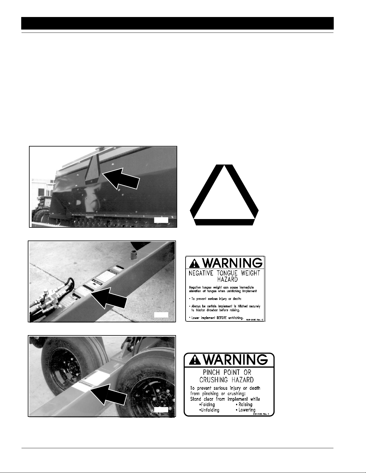
Safety Labels
Your implement comes equipped with all safety labels in place.
They were designed to help you safely operate your implement.
1. Read and follow label directions.
2. Keep all safety labels clean and legible.
3. Replace all damaged or missing labels.
4. Some new equipment installed during repair require safety
labels to be affixed to the replaced component as specified
by the manufacturer. When ordering new components make
15568
sure the correct safety labels are included in the request. To
order new labels go to your Great Plains dealer.
5. Refer to this section for proper label placement.
To install new labels:
a. Clean the area the label is to be placed.
b. Peel backing from label. Press firmly on surface
being careful not to cause air bubbles under label.
818-003C
Slow Moving VehicleLabel
15532
Negative Tongue Weight
818-045C
818-019C
15531
3S-3000 Three-Section Folding Drill 195-110M-A 11/9/07
4
Pinch PointCrushing
Page 7
Great Plains Mfg., Inc.
Important Safety Information
15532
15528
818-078C
General Instructions
838-267C
Daytime Reflector
Wing Walkboards
inside ends
11/9/07
15528
15527
838-266C
Red Reflector
Wing Walkboards
inside ends
838-265C
Amber Reflector
Center Walkboard
both ends
3S-3000 Three-Section Folding Drill 195-110M-A
5
Page 8
Important Safety Information
15528
Great Plains Mfg., Inc.
838-265C
Amber Reflector
Wing Walkboards
Backside of both ends
15566
15549
838-265C
Amber Reflector
Wing Walkboards
outside end
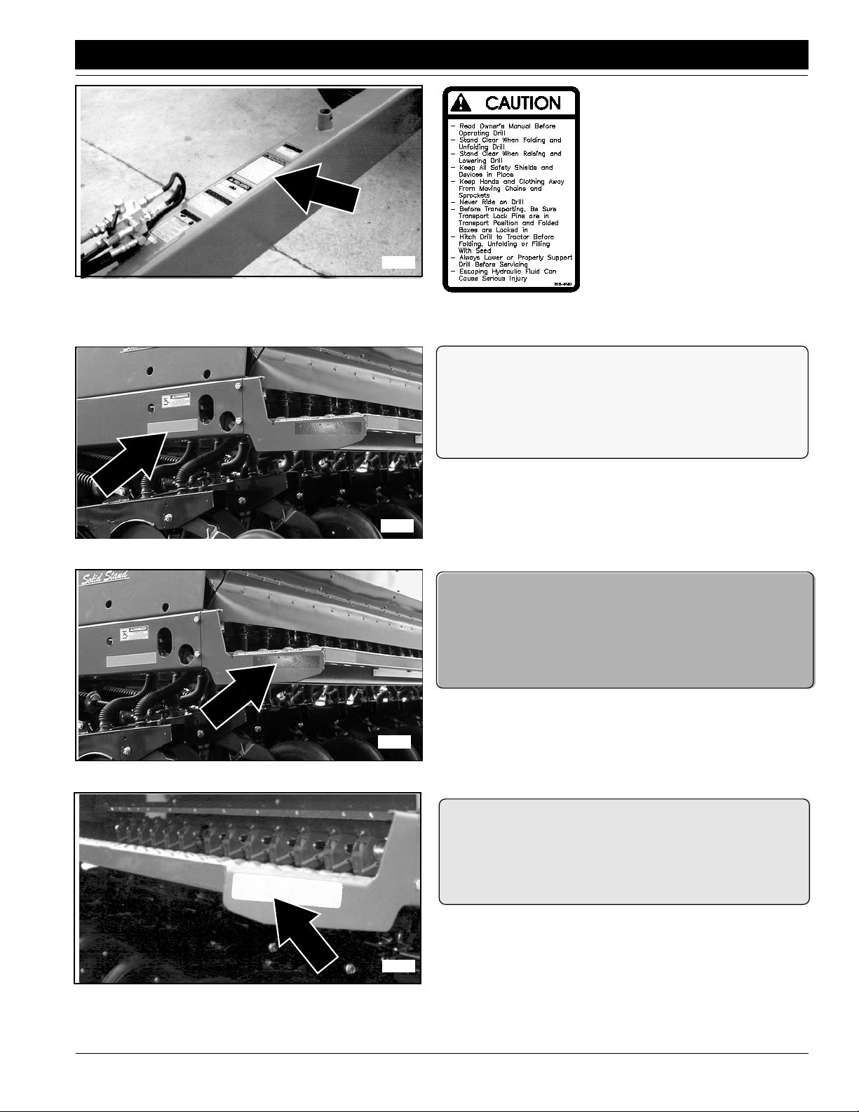
818-257C
ROAD Position
15548
3S-3000 Three-Section Folding Drill 195-110M-A 11/9/07
6
FIELD Position
818-258C
Page 9
Great Plains Mfg., Inc.
Important Safety Information
15532
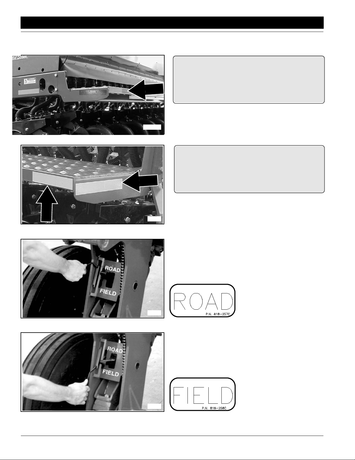
818-337C
Excessive Speed
15532
818-339C
High Pressure Fluid
11/9/07
15526
818-398C
Tire is Not a Step
3S-3000 Three-Section Folding Drill 195-110M-A
7
Page 10
Important Safety Information
Great Plains Mfg., Inc.
15532
15526
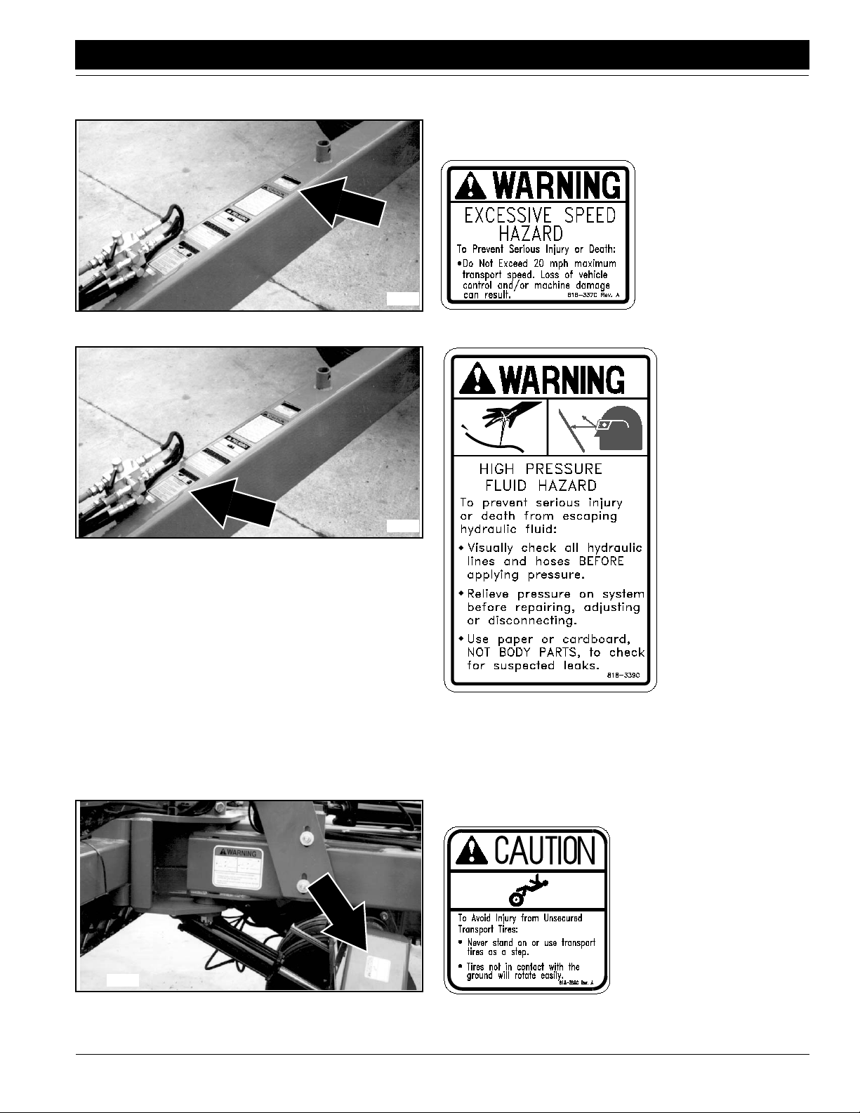
818-557C
Can Not Read English
818-660C
Transport Locks
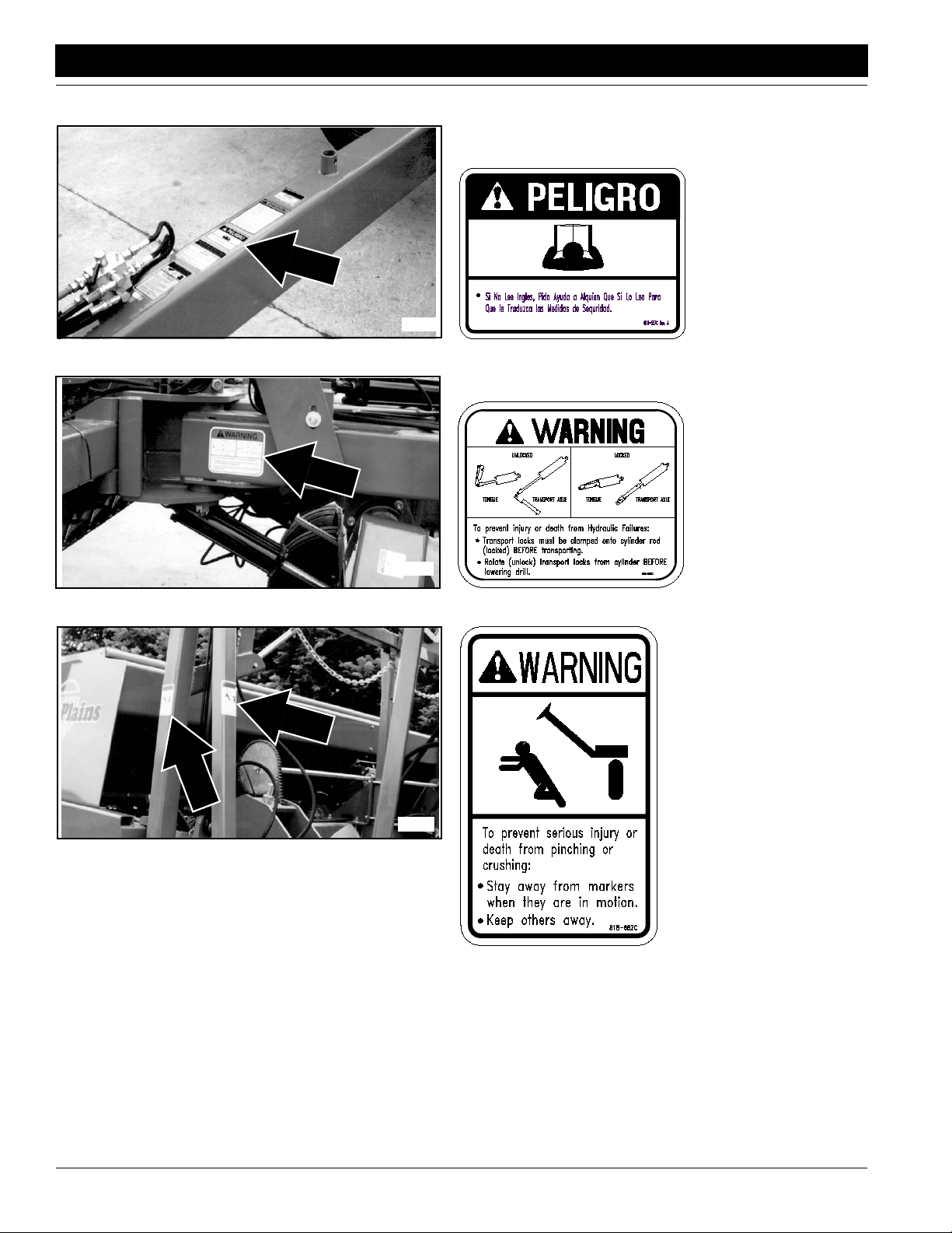
818-682C
15670
3S-3000 Three-Section Folding Drill 195-110M-A 11/9/07
8
Marker Pinch Point Crushing
Page 11
Great Plains Mfg., Inc.
Important Safety Information
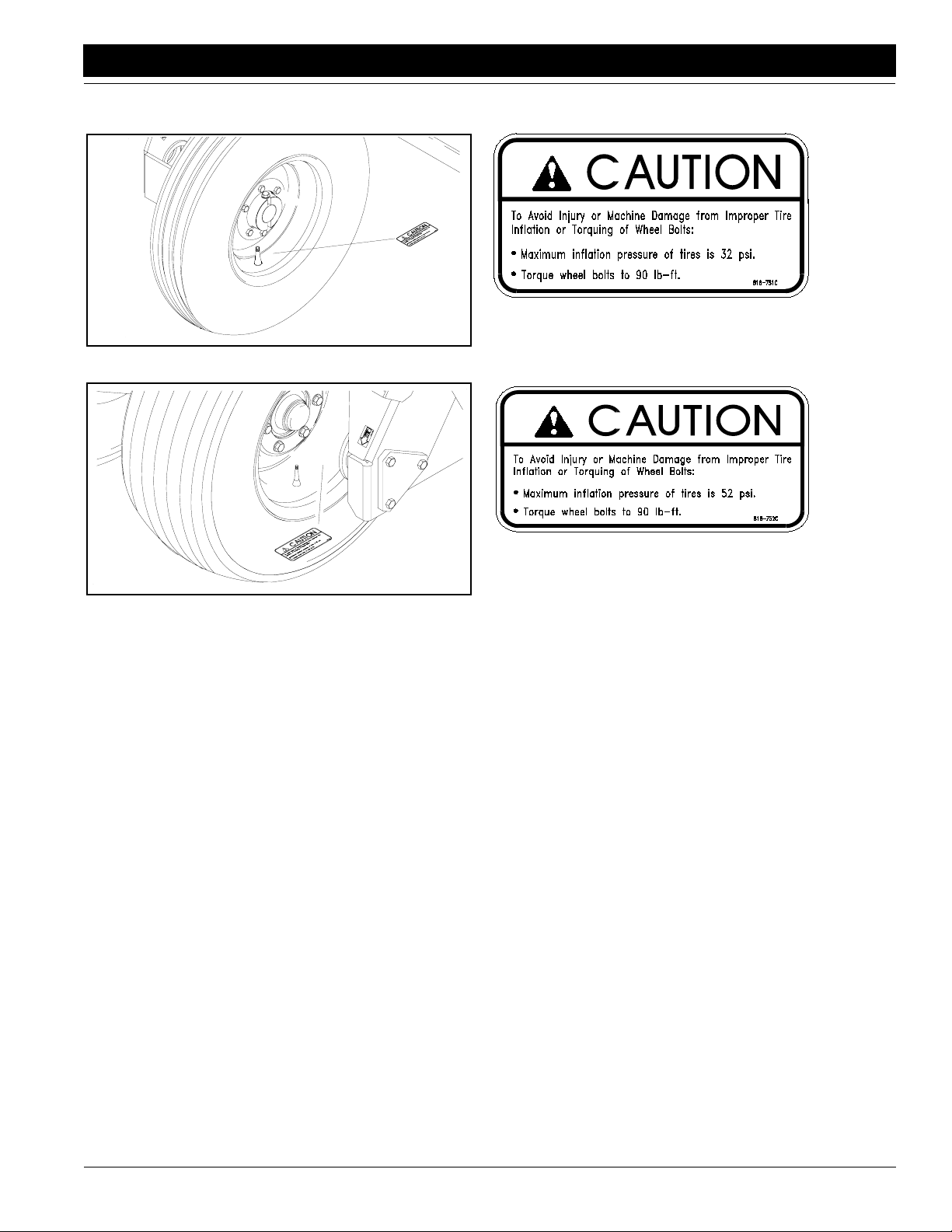
15676
15677
818-751C
Improper Tire Inflation - Wing Gauge Wheel Tires
818-752C
Improper Tire Inflation - Transport Tires
11/9/07
3S-3000 Three-Section Folding Drill 195-110M-A
9
Page 12
Introduction
Introduction
Great Plains Mfg., Inc.
Great Plains welcomes you to the growing family of new
product owners.
This implement has been designed with care and built by
skilled workers using quality materials. Proper assembly,
maintenance, and safe operating practices will help you
get years of satisfactory use from the machine.
Description of Unit
The 3S-3000 Drillis a 30 ft. 3 section grain drill which couples our solid stand double disk openers with live closedcentertractorhydraulicsto achieveconstant opener down
pressure through a wide range of opener movement. Hydraulic down pressure provides easy single point opener
pressure adjustment while providing accurate depth controland seed placementoveruneventerrain.TheT handle
adjustment on the depth controlling press wheels provide
easy seed depth adjustment for each individual row unit.
The3S-3000Fallowsyouto plant seed andapplyfertilizer
inthe same fieldpass.Dividers partitionthedrillboxesinto
seed and fertilizer compartments. The openers apply dry
fertilizerto the seed trench beforethe furrow isclosed.You
can use both compartments for seed.
Features include:
• Single tang or Clevis style hitches
• 15 degree wing box down flex and 20 degree wing box
up flex
• Floating opener frames for increased flexibility over un-
even terrain
• Multiple opener pressure valves to vary the opener
pressure from wings to center
• 4 speed drive system for a wide range of seeding rates
• Solid Stand openers
• 3.2 bushel-per-foot seed box
• Seed level gauges.
• V-bottom boxes for complete cleanout
• Internal drive gauge wheels that ride on tapered roller
bearings
• Safety lights which couple with tractor lighting system
Plains. Keep your copy in the manual for use when corresponding with the dealer.
To order a newOperator or Parts Manual contact your authorized dealer or write to the address listed below in the
Owner Assistance paragraph.Include the model and serial numbers of your unit.
The information in this manual was current at printing.
Some parts may change to assure top performance.
Definitions:
"Right " or "Left" as used in this manual is determined by
facingthe direction the machine will travelwhile in use unless otherwise stated.
NOTE: A special point of information related to it’s
preceding topic. The author’s intention is that you
read and note this information before continuing.
IMPORTANT:Aspecialpoint ofinformationthat the author
feels you must be aware of before continuing with the instructions that follow.
Owner Assistance
If customer service or repair parts are required contact
your local Great Plains dealer. He has trained personnel,
repair parts, and the equipment needed to service your
implement. These parts have been specially designed
and should only be replaced with genuine Great Plains
parts.
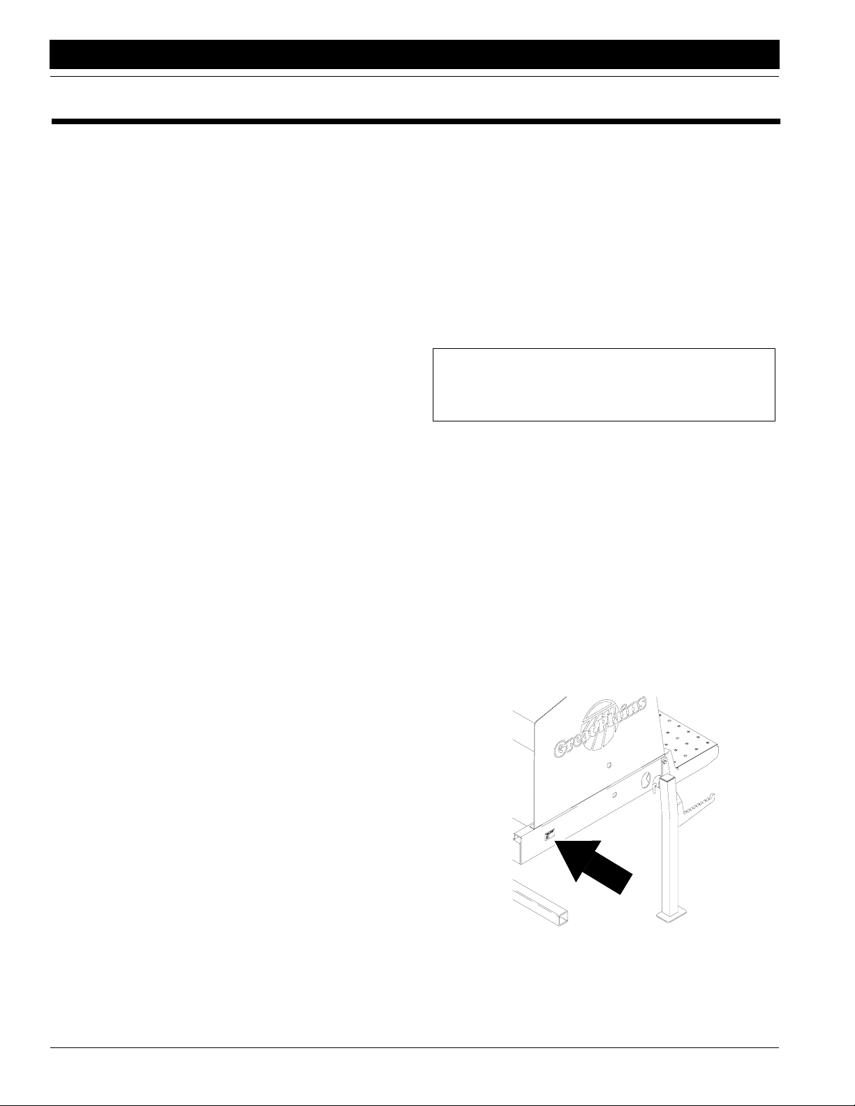
Serial Number Plate
Referto the Figure 1forthe location of yourserial number
plate.
Intended Usage
This machine is intended to be used primarily for conventional tillage applications. It has capability of some minimum or light no-till drilling.
Using This Manual
ThisOperator’sSection is designed to help familiarizeyou
with safety, operation, adjustments, troubleshooting, and
maintenance.Read this manual and followtherecommendations to help ensure safe and efficient operation.
The warranty sheet should be filled out by the owner and
dealer at the time of purchase. After completion give the
dealer the white copy and send the pink copy to Great
3S-3000 Three-Section Folding Drill 195-110M-A 11/9/07
10
Serial Number Plate Location
Figure 1
15614
Page 13

Great Plains Mfg., Inc.
Introduction
Forpromptservicealwaysusethe serial numberand model
numberwhenordering parts from yourGreat Plains dealer.
Be sure to include your serial and model numbers in correspondence also.
Your dealer wants you to be satisfied with your new machine. If forany reason you do not understand any partof
this manual or are not satisfied with the service received,
the followingactions are suggested:
1. Discuss the matter with your dealership Service Manager make sure he is aware of any problems you may
haveand that he has had the opportunity to assist you.
2. If you are still not satisfied, seek out the Owner or
General Manager of the dealership, explain the problem and request assistance.
3. For further assistance write to:
Product Support
Great Plains Mfg. Inc., Service Department
P.O. Box 5060
Salina, KS 67402-5060
11/9/07
3S-3000 Three-Section Folding Drill 195-110M-A
11
Page 14
Section 1 Drill Preparation and Setup
Section 1 Drill Preparation and Setup
Leveling the Drill
Center Box Frame Leveling
1. Park the drill on a clean level surface.
2. Raise the openers and lock them up.
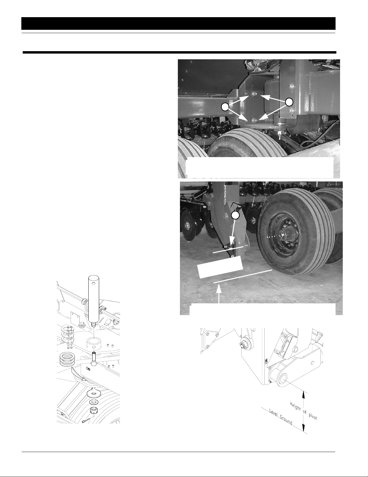
3. Loosen the eight center box mount bolts (1), four bolts
on each side of tongue, see Figure 1-1, and slide center box frame sidewaysuntil it is centered with mainframe and transport axle.
4. See Figure 1-2. Measure the height of center box
opener frame pivots (2) from the level surface and
raise low end of box frame up until both opener frame
pivots measure the same distance from the ground.
5. Torque the 7/8 inch box mount bolts (1), Figure 1-1.
Adjust Toolbar Height
The height of the Toolbars are set at the factory fora level
drill and should not require adjustment. Three spacer
washersaboveand below the toolbars at their vertical pivot pins allow for a small amount of toolbar height adjustment.Measurefrom the levelsurface to theinnerwingbox
opener frame pivots. See Figure 1-3. If the opener frame
pivotsvary more than 1/4"raise the lower toolbar upbyremoving spacer washers from the top side of the toolbar
and placing them on the bottom side of the toolbar as
shown in Figure 1-4.
It is best to lower the openers and apply enough hydraulic
pressure to them to help balance the wing frame when removing the vertical pivot pin to adjust toolbar height.
Opener
pivot
1
Center Box Mount Bolts
Figure 1-1
2
frame
height
Great Plains Mfg., Inc.
1
18873
Opener Frame Leveling
Figure 1-2
15617
Toolbar Height Adjustment
Figure 1-4
3S-3000 Three-Section Folding Drill 195-110M-A 11/9/07
12
15616
Toolbar Height Leveling Dimension
Figure 1-3
18874
Page 15
Great Plains Mfg., Inc.
Section 1 Drill Preparation and Setup
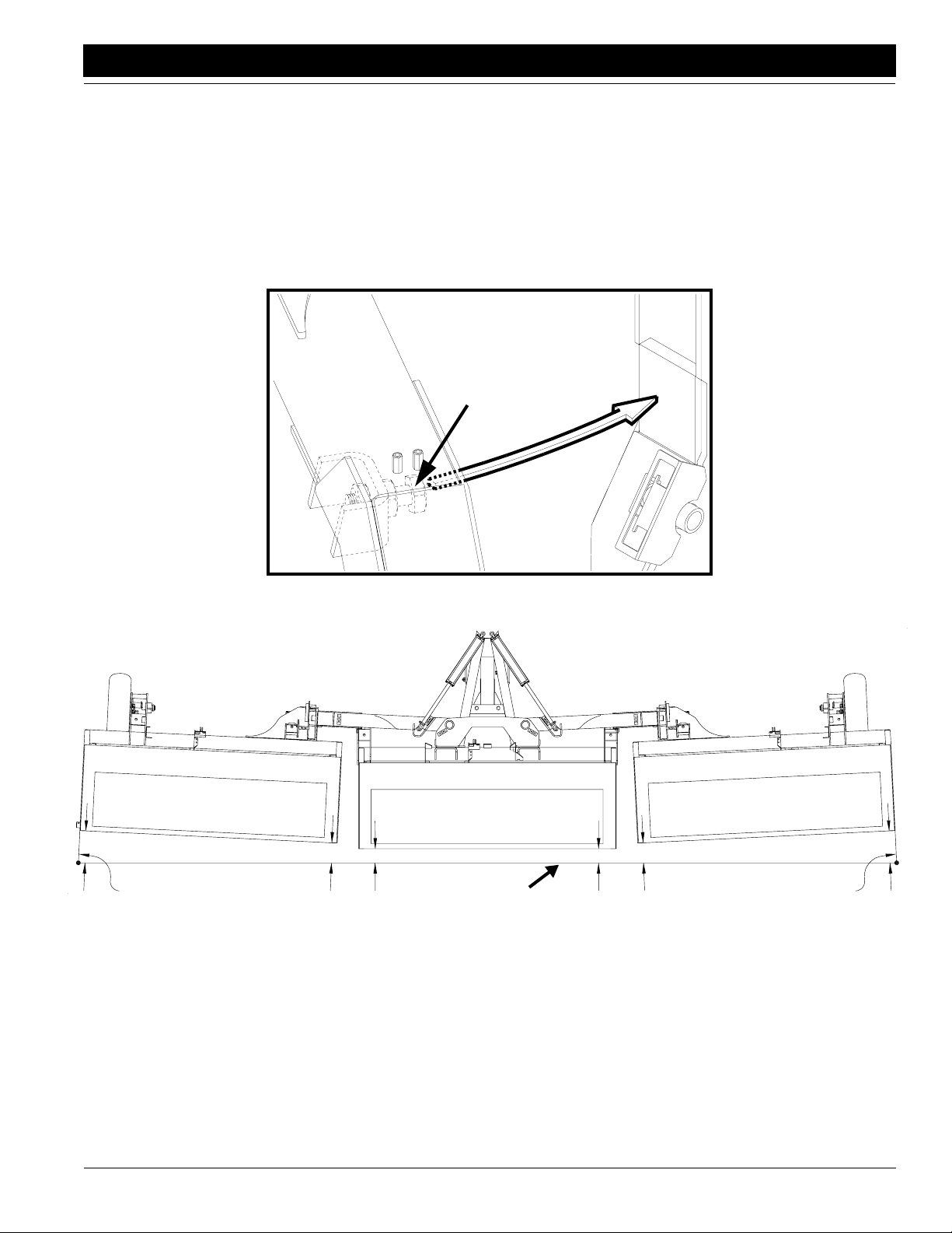
1. Adjust The Wing Box Alignment
Refer to Figure 1-5, place a 4x4 or similar sized block
ahead of the wing gauge wheels. Pull forward or rock the
wing frames back until the toolbar stop bolt is firmly
againstthestop plate on the center boxframe.The toolbar
stop bolt runs through a formed channel on the bottom
side of the toolbar. Run a string line across the back of the
Stop Bolt
center box and out toward the outer ends of the wings.
The outboard ends of the wing boxesshould be toed forwardabout1" ahead of the inboard ends.Adjust thewing
boxalignment by controlling when the 1 1/4" toolbar stop
bolt contacts the stop plate on the center box frame. Adjust the 1 1/4" toolbar stop bolts in or out until the outer
end of the wing boxes are toed forward about 1".
C
15654
String Line
Support
C-B=1"
15655
C
B
A
Wing Box Alignment Measurement
String Line
Figure 1-5
B
A
C-B=1"
String Line
Support
11/9/07
3S-3000 Three-Section Folding Drill 195-110M-A
13
Page 16
Section 1 Drill Preparation and Setup
Great Plains Mfg., Inc.
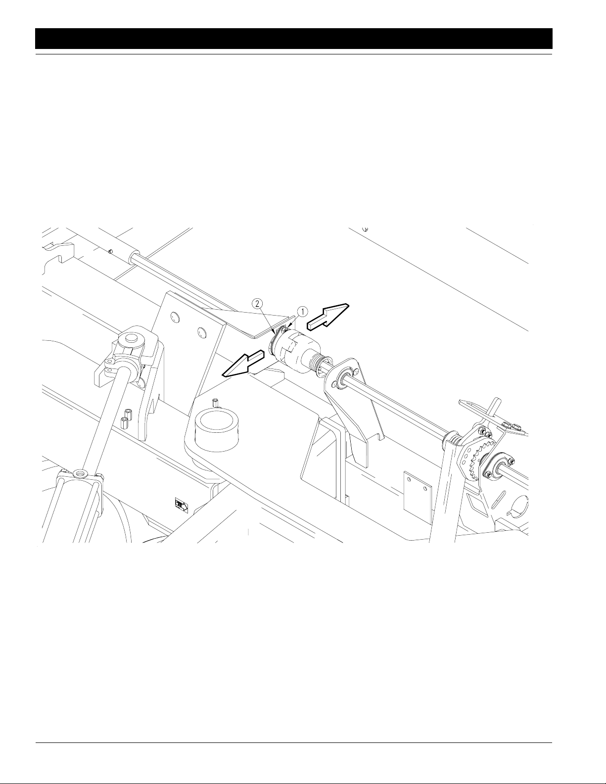
2. Align Transfer Drive Shaft
After the wing boxes are properly aligned, the transfer
driveshaft must be aligned so the pair of break-awayjaws
have full engagement and are concentric.The 7/8" hex
drive shafts holding the clutch jaws should not contact
each other when the wing boxesare properly aligned and
back against their stop. Place a 4x4 or similar sized block
ahead of the wing gauge wheels and pull forward or push
the wing box frames backuntil the toolbar stop bolt is firmly against the stop plate on the center box frame.
Toaligntheclutch jaws in thefronttoreardirection,loosen
the two 5/16" (#1) bolts which hold the 7/8" hex bearing
flangettes (#2) and slide the bearing assembly in the desired direction, as shown in Figure 1-6.
Transfer Drive Shaft Front to Rear Adjustment
Figure 1-6
3S-3000 Three-Section Folding Drill 195-110M-A 11/9/07
14
15620
Page 17
Great Plains Mfg., Inc.
Section 1 Drill Preparation and Setup
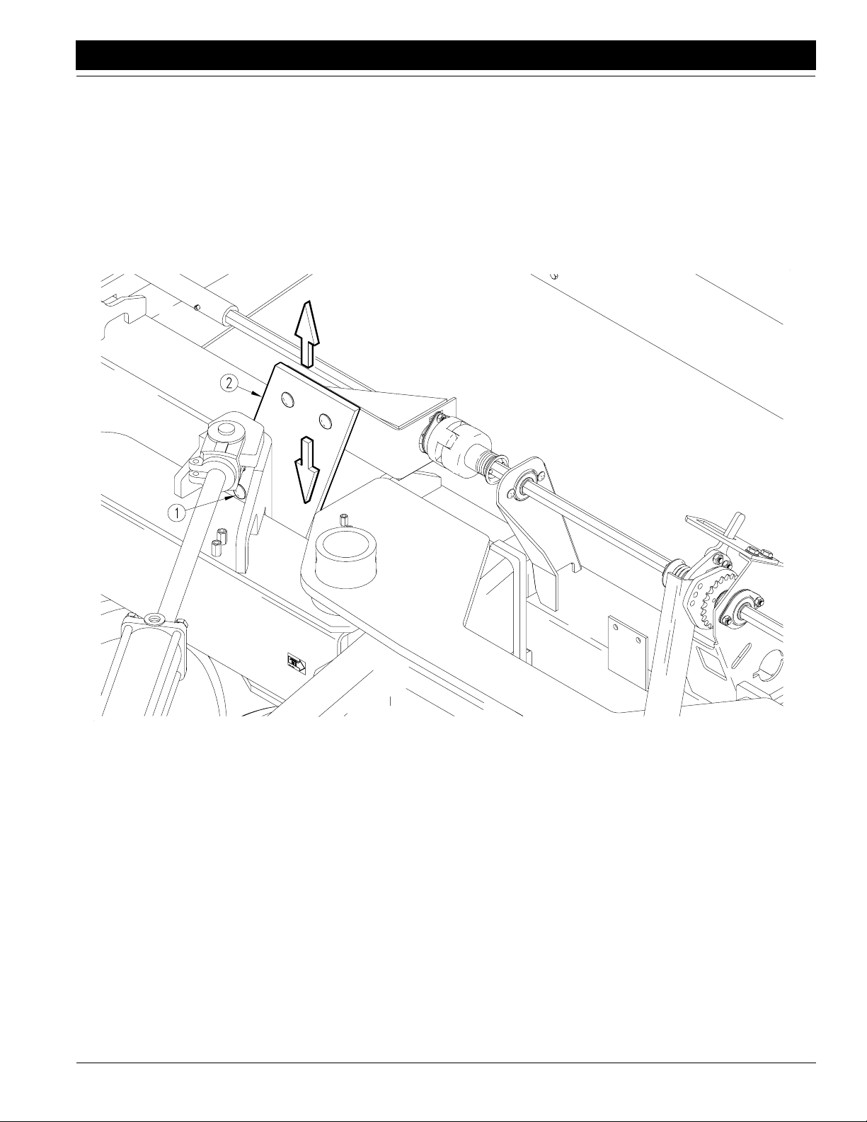
To align the clutch jaws in thevertical direction, loosen the
two 5/8" bolts (#1) on the break-awayadjustment plate at
thebacksideof the toolbar and slide the 1/2"(#2)plate up
or down in the desired direction, as shown in Figure 1-7.
11/9/07
Transfer Drive Shaft Vertical Adjustment
Figure 1-7
3S-3000 Three-Section Folding Drill 195-110M-A
15621
15
Page 18
Section 1 Drill Preparation and Setup
Great Plains Mfg., Inc.
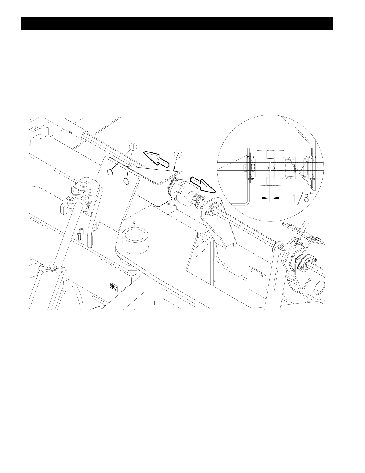
Toadjustthe clutch jawsforfull jawcontact,loosen the two
1/2" (#1) bolts which fasten the bearing bracket(#2) to the
1/2" adjustment plate and slide the bearing bracket until
the jaws on the fixed half of the clutch make full contact
withthe jaws onthespringloadedhalfofthe clutch without
compressing the clutch spring, as shown in Figure 1-8.
The two 7/8" hex shafts should have 1/8" between them
when the clutch jaws have full contact.
Top View
Transfer Drive Shaft Clutch Jaw Adjustment
Figure 1-8
3S-3000 Three-Section Folding Drill 195-110M-A 11/9/07
16
15622
Page 19
Great Plains Mfg., Inc.
Section 1 Drill Preparation and Setup
Tractor Drawbar Hookup
The Great Plains 30 ft 3 section drill has three hitch options: a clevis hitch, a small hole single strap hitch, and a
large hole single strap hitch. Use the single strap hitch for
tractors with clevis drawbars, and use the clevis hitch with
tractors which have single tang drawbars. In either case
alwaysuse a locking style drawbar pin sized to match the
holes in the hitch and drawbar.
!
WARNING!
Since this drill can have both positive and negative hitch forces
always use a clevis hitch or clevis drawbar with a locking style
hitch pin through the clevis.
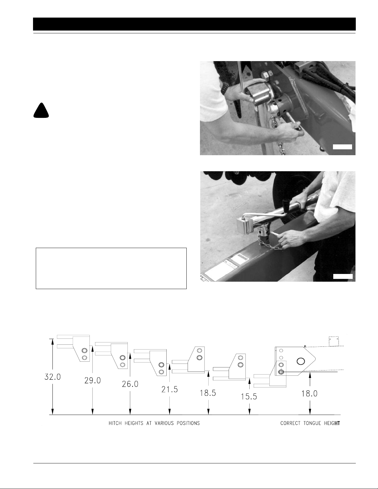
TheGreatPlains 30 ft 3 section drill is designed to operate
with the lowest hitch hole in the tongue measuring about
18" off the ground when in FIELD (lowered) position. The
mounting holes in the hitch have been offset so the hitch
can be turned overand bolted onin three positions, giving
you six hitching positions. Use the screw jack to raise the
front of the drill tongue so the lowest hitch hole in the
tongue measures 18" off the ground. Adjust the drillhitch
to match your tractor drawbar. See Figure 1-9. The drill
hitch can accommodate tractor drawbars ranging from
15.5 to 32 inches high.
Your drill is equipped with a hitch safety chain. The safety
chainshouldbe securely attached to the drill hitch andthe
tractor whenever towing or planting.
Use the jack to raise and lower the front of the drill when
hitching to the tractor, and store it in the storage tube on
the top of the tongue as shown in Figure 1-11.
15564
Jack Lifting Position
Figure 1-10
NOTE: When hitching the drill to a different tractor,
check for a difference in drawbar heights. If the
heights are different, the hitch height must be readjusted accordingly.
Hitch Height Adjustment
15563
Storing Tongue Jack
Figure 1-11
15623
Figure 1-9
11/9/07
3S-3000 Three-Section Folding Drill 195-110M-A
17
Page 20
Section 1 Drill Preparation and Setup
Great Plains Mfg., Inc.
Tractor Hydraulic Hookup
!
WARNING!
Escaping fluid under pressure can penetrate the skin causing
serious injury. Avoid the hazard by relieving pressure before
disconnecting hydraulic lines. Use a piece of paper or cardboard, NOT BODY PARTS, to check for suspected leaks. Wear
protective gloves and safety glasses or goggles when working
with hydraulic systems. If an accident occurs, see a doctor immediately.Any fluid injected into the skin must be surgically removed within a few hours or gangrene may result.
NOTE: To run drill on tractors with open-center hydraulics or on tractors with fixed-displacement hydraulic pumps, you must install a Great Plains kit, part
number 194-143A. If you are not familiar with your
tractor hydraulics, consult your tractor dealer.
Great Plains hydraulic hoses are color coded to help you
hook up hoses to yourtractor outlets. Hoses that go to the
same remote valve are marked with the same color.
Color Hydraulic Function
Red Opener Lift
1. Connect opener-lift hoses to circuit designated for hydraulic-motor control.
2. Connect transport-lift hoses to tractor remote valve.
3. Connect fold hoses to tractor remote valve.
IMPORTANT: If your tractor has only two remote valves,
you must install a double-selector valve to combine the
transport-lift and opener-lift circuits. Refer to 3S-3000
Two-Outlet TractorHydraulic Kit,“Options,” page 61.
Safety Lights
The light package that yourdrill is equippedwith, requires
that your tractor have the correct electrical connections.
Your tractor should be wired fora standard 7-pin electrical
connector which works with the tractor'sflashers and turn
signals. All that should be necessary to hook up the lights
is to plug them into the tractor's 7-pin connector.
If your tractor is not equipped with a 7-pin connector,
please contact your local dealer for installation to your
tractor manufacturers specifications.
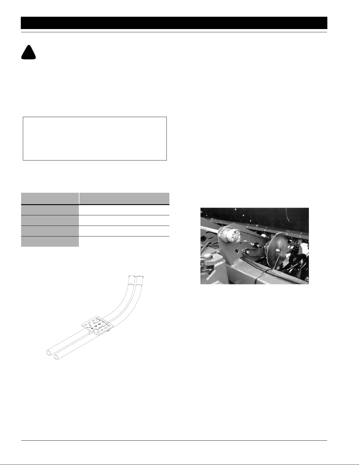
Acre Meter
Assemblethe acre meter to the end of the main drive shaft
onthe center section as shownin Figure1-13. Record the
acres before you begin planting and subtract that number
from the final reading to get acres planted.
Blue T ransport Lift
White Fold
Orange Marker
Todistinguishhoses on the same hydraulic circuit, refer to
plastic hose holders. See Figure 1-12. Hoses under extended-cylinder symbol feed cylinder base ends. Hoses
under retracted-cylinder symbol feed cylinder rod ends.
17641
Hydraulic Hose Label
Figure 1-12
Acre Meter Location
Figure 1-13
15660
3S-3000 Three-Section Folding Drill 195-110M-A 11/9/07
18
Page 21
Great Plains Mfg., Inc.
Section 1 Drill Preparation and Setup
Bleeding the Hydraulic Systems
NOTE:Check hydraulic fluid levelin tractor reservoir
and fill it to proper level before starting this procedure. Add fluid to system as needed. A low reservoir
levelmay drawair back into the system causing jerky
or uneven cylinder movements. System capacity for
entire drill is approximately 4 1/2 gallons.
!
CAUTION!
This drill has a negative tongue weight when unfolded and the
openers raised. Be certain that the drill is hitched securely to
your tractor drawbar and be certain the safety chain is securely
attachedto the tractor before raising the openers and unfolding
the drill.
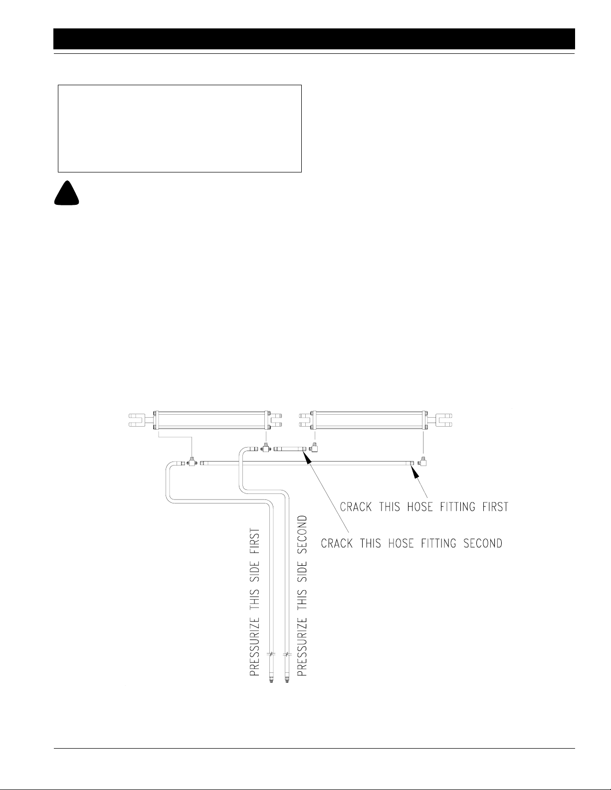
Bleeding the Fold Hydraulics
Refer to Figure 1-14:
1. With the drill unfolded (the fold cylinders completely
extended),disconnect the rod end pins and swingthe
cylinders so they will not catch or contact anything
during the bleeding process.
2. Loosen the rod end hose fitting at the elbowon the left
fold cylinder.
3. Slowly supply oil to the rod end of the fold cylinders
until oil appears at the loosened hose fitting. Tighten
therod end hose fitting and completelyretractthe fold
cylinders.
4. With the cylinders completely retracted, loosen the
base end hose fitting at the elbow on the left fold cylinder.
5. Slowly supply oil to the base end of the fold cylinders
until oil appears at the loosened hose fitting. Tighten
thebase end hosefittingandcycle the foldcylinders in
and out several times.
6. Repin the cylinder rod clevis.
11/9/07
Bleeding the Fold Hydraulics
Figure 1-14
3S-3000 Three-Section Folding Drill 195-110M-A
15644
19
Page 22
Section 1 Drill Preparation and Setup
Great Plains Mfg., Inc.
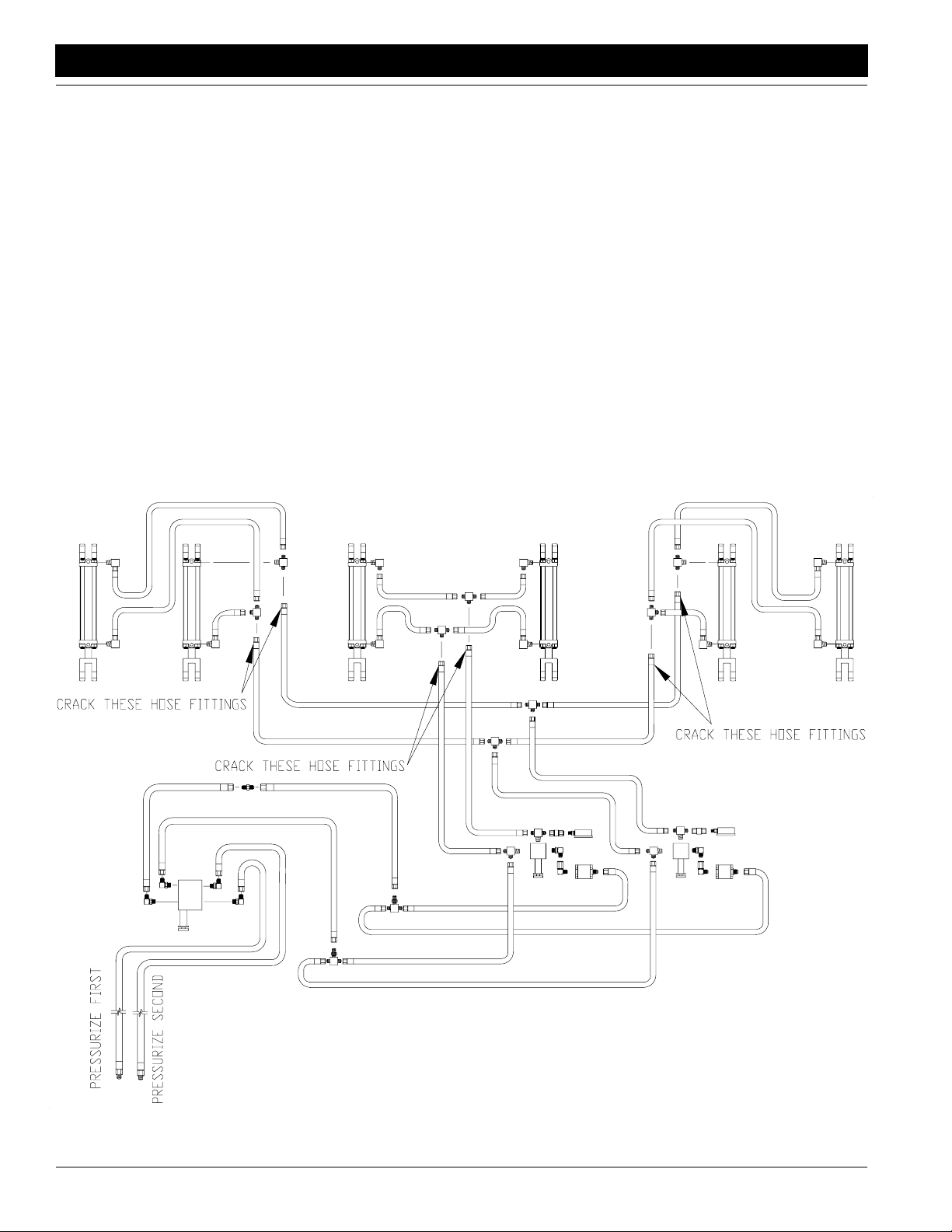
Bleeding the Opener Lift Hydraulic System
Refer to Figure 1-15:
1. Check that opener frames are locked in ROAD position.
2. Turn knobs on pressure-control valves completely
counterclockwise, then turn knobs clockwise three
turns.
3. Turn knob on bypass valve completely clockwise for
no oil flow.
4. Loosen six hose-end fittings at three locations on
opener-lift circuit:
• both JIC fittings on thetwo 3/8" opener lift hoses ex-
tending from the end of each wing toolbar,
• the JIC fittings on the two 3/8" opener lift hoses
feeding the center opener lift cylinders, and
• the end where these center two hoses tee at the
middle of the center box frame.
5. Slowly supply oil to top side of pressure-control
valves.As oil begins to appear at a fitting, tighten that
fitting. Continue supplying oil until one of the two fittings is tightened at each of the three locations.
6. Slowly supply oil to bottom side of pressure-control
valves.As oil begins to appear at a fitting, tighten that
fittinguntil all hosefittingsare tight. Continuetosupply
oil to bottom side of pressure-control valves until
openers are raised completely.
7. Move opener transport hooks to FIELD position and
cycleopeners up and downabouttentimes. Each time
you pressure openers down, hold tractor remote lever
until opener circuit builds up to pressure you have set
at control valves. Turn knobs on pressure-control
valvesclockwise far enough to build up at least 1000
psi on pressure gauges when cycling openers.
8. Onceopeners havebeencycled,return transport hooks
to ROAD position and lock openers up.
20009
Bleeding the Opener Lift Hydraulics
Figure 1-15
3S-3000 Three-Section Folding Drill 195-110M-A 11/9/07
20
Page 23

Great Plains Mfg., Inc.
Section 1 Drill Preparation and Setup
Bleeding the Transport Lift Hydraulics
Refer to Figure 1-16:
1. Start with the transport axle in the lowered (field) position, and the box lift cylinder (at the middle of the
tongue) completely retracted. Loosen the base end
hose fitting at the elbow on the left transport lift cylinder and the base end hose fitting on the box lift cylinder at the middle of the tongue.
2. Slowly supply oil to the base end of the transport lift
cylinders until oil appears at the loosened hose fittings. Oil may not appear at both location at same
time.As oil begins to appearat a fitting, tighten thatfitting and proceed until both fittings have been tightened. Completely extend the transport lift cylinders
andIMMEDIATELY lock the cylindersupbyflipping up
the cylinder lock channels on both transport lift cylinders and the box lift cylinder at the middle of the
tongue.
!
WARNING!
NEVER CRAWL UNDER THE DRILL IN THE RAISED POSITON WITHOUT THE CYLINDER LOCK CHANNELS IN
PLACE.
3. When the cylinder lock channels are in place, loosen
the rod end hose fitting at the elbow on the left transport lift cylinder and the rod end hose fitting on the box
lift cylinder at the middle of the tongue.
4. Slowly supply oil to the rod end of the transport lift cylinders until oil appears at the loosened hose fittings.
As oil begins to appear at a fitting, tighten that fitting
and proceed until both fittings have been tightened.
5. Extend the transport lift cylinders, and removethe cylinderlockchannels. Completelycyclethetransport lift
hydraulics several times.
11/9/07
Bleeding the Transport Lift Hydraulics
Figure 1-16
3S-3000 Three-Section Folding Drill 195-110M-A
15645
21
Page 24

Section 2 Operating Instructions
Section 2 Operating Instructions
Lifting
The openers are raised and lowered on their own hydrauliccircuit. To operatethemwith livehydraulicpoweralways
connect the opener lift circuit to the #1 remote hydraulic
circuit or the circuit designed for HYDRAULIC MOTOR
control. On many CLOSED CENTER or PRESSURE/
FLOWCOMPENSATEDtractorsthe #1circuitisthe circuit
designed to supply live hydraulic power to remote locations.
The openers can be locked up for transportingor for working under the drill. To lock the openers up, position the
opener transport lock handles in the ROAD position Figure 2-1 and completely raise the openers.
Great Plains Mfg., Inc.
15548
15549
Opener Frames Locked Up (Handles in ROAD Position)
Figure 2-1
To unlock the openers, position the opener transport lock
handles in the FIELD position Figure 2-2 and completely
raise the openers to allow the opener transport locks to
disengage. There are two lock handles on each drill section.
Opener Frames Unlocked (Handle in FIELD Position)
Figure 2-2
Folding
1. Folding is best achievedon level ground with the tractor transmission in neutral. Be aware of the clearance
required to fold the drill.
!
CAUTION!
NEVER allow anyone near the drill during folding operations.
2. Position the opener transport lock handles in the
ROAD position Figure 2-1 and completely raise the
openers. The opener transport lock handles are
springloadedand can bemovedtotheROADposition
withthe openers up or down, but the locks will only engage when the openers are completely raised. There
are two lock handles on each drill section.
3. Make sure the transport lift cylinders and front box lift
cylinder are completely retracted.
3S-3000 Three-Section Folding Drill 195-110M-A 11/9/07
22
Page 25

Great Plains Mfg., Inc.
Section 2 Operating Instructions
4. Slowly supply oil to the rod end of the foldcircuit.Completely fold the wing frames until both wing gauge
wheels contact the tongue tube.
5. Supply oil to the transport lift circuit until the transport
lift cylinders and front box lift cylinder are completely
extended and the drill is completely raised.
6. Rotate the cylinderlockchannels overtherods on the
twotransportliftcylinders and front-box,lift cylinderas
shown in Figure 2-3.
NOTE: Make sure the u-shaped clips in the lock
channels clasp the cylinder rods securely. The clips
must hold the channels in position until the cylinders
settle against the channels. You may need to adjust a
clip by turning the bolt inside the channel.
7. Allow the transport-lift cylinders to settle back against
the lock channels.
8. Beforetransporting, checkthatthehydrauliccylinders
havesettledagainstthe lockchannelsand are holding
the channels securely.
Unfolding
1. Supplyoil to the transportlift circuit until the transport lift
cylinders and front box lift cylinder are completely extended(thedrilliscompletelyraised).Rotatethecylinder
lock channels off the rods of the transport lift cylinders
and front box lift cylinder,as shown in Figure 2-4.
15551
Transport Lift Cylinder
Cylinder Lock Channels Inserted for Transporting
Front Box Lift Cylinder
Cylinder Lock Channel Inserted for Transporting
Figure 2-3
11/9/07
15552
15631
15553
Transport Cylinder Lock Channels Removed
for Field Use
Figure 2-4
2. Completely retract the transportlift cylinders and front
box lift cylinder.
3. Slowly supply oil to the baseendof the foldcircuit. Unfold the wing frames by completely extending the fold
cylinders.
4. Position the opener transport lock handles in the
FIELDposition, as shown back in Figure 2-2 and com-
3S-3000 Three-Section Folding Drill 195-110M-A
23
Page 26

Section 2 Operating Instructions
pletelyraisetheopenerstoallowthe opener transport
lockstodisengage.Theopener transport lock handles
are springloaded and can be moved to the FIELD position with the openers up or down, but the locks will
only disengage when the openers are completely
raised.There are two lockhandlesoneachdrillsection.
Transporting
!
CAUTION!
This drill should never be pulled faster than 20 miles per hour!
Before transportingthe drill check the following items.
1. Transport only with a tractor of proper size. See Trac-
tor Requirements in the “Drill Preparation and Set-
up” section on page 17.
2. The drill must be hitched securely to tractor. Always
use a locking style drawbar pin sized to match the
holes in the hitch and drawbar (minimum of 1" diameter).
3. The safety chain should be securely attached to the
drill hitch and the tractor.
4. The Safety Lights must be plugged in with tractor
lights using the standard 7-pin terminal.
5. Make sure the drill is properly folded. Refer to Folding
on page 22.
6. The opener transport lock handles should be in the
ROADposition and the openers completely raised for
the opener locks to engage and lock the openers up.
There are two lock handles on each drill section.
7. The cylinder lock channels must be on the rods of the
twotransportlift cylindersandfront boxliftcylinder.As
shown back in Figure 2-3, allow the transport lift cylinders to settle back against the lock channels.
Marker Transportation
Always transport the marker with it folded in the flat position. Make sure the second marker section rests securely
on the transport carrier.
Great Plains Mfg., Inc.
Jack Lifting Position
Jack Storage Location
Using and Storing the Front Tongue Jack
Figure 2-5
15564
15563
Parking
Unhitching with the drill unfolded.
!
CAUTION!
This drill has a negative tongue weight when unfolded and the
openers raised. Do not unhitch the drill in the unfolded position
without first lowering the parking stand and pressurizing the
openers down. Unhitching in the unfolded position with the
openers raised could result in sudden elevation of the tongue
causing injury or death.
1. Removethejack from itsstoragelocationon top of the
tongue and pin it in the post located on the left side of
the tongue, refer to Figure 2-5. Extend the jack until
weight of the tongue is on the jack.
3S-3000 Three-Section Folding Drill 195-110M-A 11/9/07
24
2. Lower the parking stands located at the outer end of
each wing box by unpinning the keeper pin and rotating the stand down. See Figure 2-6. Place a block under the foot of the stand if it does not contact the
ground.
Page 27

Great Plains Mfg., Inc.
Section 2 Operating Instructions
15565
Parking Stand Positioned for Unhitching
Using and Storing the Parking Stands
Figure 2-6
3. Lower the openers and pressure them down.
4. Unplug the drills’ hydraulic lines and electrical lines
from the tractor.
5. Removethehitchpinandsafetychain from the tractor
drawbar. Use caution when removing the hitch pin because a slight tongue elevation might still occur.
NOTE:After the drill has been unhitched fora time in
the unfolded position the tongue may rise above the
tractor drawbar height. Lower the tongue back down
by connecting the opener lift circuit and pressuring
the openers back down.
15566
Parking Stand Storage Position
Unhitching with the drill folded.
1. Fold, raise, and lock the drill in the transport position.
2. Park the drill on a level, solid area.
3. Removethejack from itsstoragelocationon top of the
tongue and pin it in the post located on the left side of
the tongue, refer back to Figure 2-5. Extend the jack
until weight of the tongue is on the jack. If the ground
is soft, place a board or plate under the jack to widen
the ground contact area.
4. Unplug the drills’ hydraulic lines and electrical lines
from the tractor.
5. Removethehitchpinandsafetychain from the tractor
drawbar.
11/9/07
3S-3000 Three-Section Folding Drill 195-110M-A
25
Page 28

Section 2 Operating Instructions
Great Plains Mfg., Inc.
Setting the Bypass Valve
A bypass valveis plumbed into the opener downpressure
circuit. See . Tractors with load-sensing, closed-center hydraulics require this bypass valveto protect the tractor hydraulic system.
If you are unsure what type of hydraulicsystem is on your
tractor,contact your tractor manufacturer.
19045
Bypass Valve
Figure 2-7
downpressure so gauges are at 1800 psi. See Figure
2-6.
15557
Opener Down Pressure Control Valves
Figure 2-8
Tractors with Open Center Hydraulics
Closebypassvalvefor no oil flow by turningknob on valve
clockwise completely. Always operate the drillwith the bypass valveclosed.
Tractors with Pressure Compensating Closed Center
Hydraulics (PC Closed)
Closebypassvalvefor no oil flow by turningknob on valve
clockwise completely. Always operate the drillwith the bypass valveclosed.
Tractors with Load Sensing Closed Center Hydraulics
(LS Closed) or Pressure Flow Compensating (PFC)
Systems
IMPORTANT: Failure to use the bypass valve on loadsensing tractors may cause major tractor damage.
1. Close bypass valvefor no oil flow by turning knob on
valve clockwise completely.
2. With tractorathalf throttle, adjustflow-controlvalveon
tractor so openers raise and lower at a reasonable
speed. Keeptractor at one-half throttle for remaining
steps.
NOTE:The fasteropenersraise and lower,the greater potential for oil heating, premature wear or tractor damage.
5. While watching gauges on drill, slowly turn knob on
bypass valve counterclockwise. Adjust bypass valve
justuntil needles on gauges begin to move down from
1800 psi. Lock bypass valve at this setting. (See also
note below.)
6. Adjust pressure-control valves on drill to desired
opener down pressure as explained under Opener
Down Pressure, beginning on page 40.
NOTE: The higher the bypass pressure, the greater the
potential for oil heating and premature tractor damage. At
the same time, for proper opener operation the bypass
valvemust be set at least 300 psi above the opener downpressure setting when the tractor is at one-half throttle.
Therefore,you should set the bypassvalveas low as possiblewhilestayingat least300 psi abovetheopener down
pressure setting.
While 1800 psi is a good starting point for setting the bypass valve, if you consistently operate the drill with low
opener down pressure you can set the bypass valve below 1800 psi. If you consistently operate the drill with very
highopener down pressure,youmayneedabypass-valve
setting above 1800 psi.
3. Engage tractor hydraulics and lower openers. Lock
hydraulic lever on tractor for continuous operation.
4. Adjust pressure-control valves on drill for opener
3S-3000 Three-Section Folding Drill 195-110M-A 11/9/07
26
Page 29

Great Plains Mfg., Inc.
Section 2 Operating Instructions
Field Operation
The openers are mounted on floating opener frames
which followthe contour of the ground while maintaining
constant opener down pressure. To achievethe designed
opener flotation the opener hydraulic circuit must be powered by an active hydraulic system. An active hydraulic
system requires a tractor with closed-center hydraulicsor
pressure/flowcompensatedhydraulicswhichare powered
by a variable-displacement hydraulic pump.
To run the drill on tractors with open-center hydraulics or
on tractors with fixed-displacement hydraulic pumps requiresakit (Great Plains partnumber 194-143A). Referto
Non-ActiveHydraulicson page 28 foradjusting a drill with
Non-Active Hydraulics.
IMPORTANT: Tractors with load-sensing hydraulics
must use the bypass valve to operate the 3S-3000.
Failureto use the bypass valve can cause major tractor damage. Before adjusting opener down pressure,
set bypass valve as explained under Setting the By-
pass Valve, page 26.
Active Hydraulic System
(Tractors with closed-center hydraulic systems and
variable-displacement hydraulic pumps)
1. Lower the opener frames by pushing FORWARD on
the tractor remote hydraulic lever. The remote lever
must be LOCKED OPEN in this position to provide
constant pressure/flow to the openers.
John Deere tractors with Sound-Gard ® Body: Use
leverlock clip, John Deere part number R52667, to
lock lever forward. See your tractor dealer for clip purchase and installation.
John Deere 7000 Series tractors: Rotate valve
detent selector to motor position to lock lever in forward position.
John Deere 8000 Series tractors: Set timer to con-
tinuous. Push lever forward until detent clicks.
Case-IH Magnum tractors: Lock lever forward in
detent position. You may need to turn up detent pressure to its maximum setting. Do not tie hydrauliclever
past detent position with a strap. See your tractor
dealer for hydraulic-system details.
Other tractors: Lock leverforward in detent position.
You mayneedto turn updetent pressure to maximum
or use a mechanical detent holder to hold lever forward.See your tractor dealerforproper means of providing constant flow to openers.
2. With thetractorhydraulicleverlockedforward,turnthe
knob on the pressure control valves as shown in Figure 2-9. Watch the pressure gauge and dial in the desired pressure on the openers. Clockwise increases
the pressure and counterclockwise decreases pressure. Once the pressure is set, lock each knob with
the lock disk. There is one pressure control valve for
the center section, and one for the wing sections. In
some typical applications, the pressure on the center
sectionis set slightly higher thanthe wings to account
for additional compaction from the drill transport tires
and tractor tires. The recommended pressure range
fordrilling isbetween200 psi and1200psi. Setting the
opener down pressure above 1600 psi. will raise the
drivewheelsoffthegroundwhentheseedboxis empty causing skips and poor seed metering. See Plant-
ing Adjustments in the “Adjustments” section
starting on page 38 to convert hydraulic pressure at
the gauge to opener down force.
Pressure Control Valves
Figure 2-9
15639
11/9/07
3S-3000 Three-Section Folding Drill 195-110M-A
27
Page 30

Section 2 Operating Instructions
Great Plains Mfg., Inc.
3. After the opener pressure is set, opener depth is controlledbythepress wheel adjustment. Attached to the
rear of each opener is one of several optional press
wheels.The press wheels close thefurrowand gently
press soil over the seed while also providing depth
control for the opener. To adjust the position of the
press wheel, which automatically changes the seeding depth of the opener, lift the "T" handle located on
top of the opener and slide it forward or rearwarduntil
the seeding depth is correct, as shown in Figure 2-10.
Moving the handle forward plants shallower while
moving the handle rearward plants deeper.A spring
loaded pin holds the "T" handle at the setting to maintaintheproperdepth.Lifttheopenerframesslightly to
take the pressure off the "T" handles when adjusting
the press wheel depth.
15659
Press Wheel Adjustment
Figure 2-10
NOTE:The opener pressure setting controls the soil
firming pressure on the press wheel as well as the
disk penetrating force. DO NOT use more opener
down pressure than necessary to obtain the desired
opener penetration and to maintain the proper firming action over the seed. Set the planting depth with
the depth controlling press wheel and only use
enough opener pressure to cut the proper seed
groove and maintain the desired soil firming action.
Excessive opener force will lead to excessive wear
and damage of the opener components.
To operate markers and constant opener down pressure
atthesame time, connect theopenerstocircuit#2 and the
markers to circuit #3.
Non-Active Hydraulic System
(Tractors with open-center hydraulic systems or
fixed-displacement hydraulic pumps)
To run the drill on tractors with open-center hydraulics or
on fixed-displacement hydraulic pumps requires a kit
(Great Plains part number 194-143A). This kit utilizes a
non-active hydraulic system which allows you to pressurize your openers down and lock in that pressure on level
ground by holding the opener frames in a fixed position.
1. Lower the opener frames by pushing FORWARD on
the tractor remote hydraulic lever. The remote lever
must be TEMPORARILY LOCKED OPEN in this position while the pressure adjustment is being made to
provide constant pressure and flow to the openers.
2. With thetractorhydraulicleverlockedforward,turnthe
knob on the pressure control valves as shown in Figure 2-9. Watch the pressure gauge and dial in the desired pressure on the openers. Clockwise increases
the pressure, and counterclockwise decreases pressure. Once the pressure is set, lock each knob with
the lock disk. There is one pressure control valve for
the center section and one for the wing sections. In
some typical applications, the pressure on the center
sectionis set slightly higher thanthe wings to account
for additional compaction from the drill and tractor
tires. The recommended pressure range for drillingis
between 200 psi and 1200 psi. Setting the opener
down pressure above 1600 psi. will raise the drive
wheels off the ground when the seed box is empty
causing skips and poor seed metering. See “Fertiliz-
erAdjustment”onpage 38toconverthydraulicpressure at the gauge to opener down force.
3. After the opener pressure is set, RETURN THE
TRACTOR REMOTE HYDRAULICLEVER TO ITS
NEUTRAL POSITION. This "locks in" the previously
selected pressure and the opener frames remain in a
fixed position.
NOTE: Open center tractors and tractors with fixed
displacement pumps are not designed to provide a
continuous supply of pressurized oil to remote locations. Attempting to continuously supply oil to the
pressure control valves will cause your tractor hydraulic pump to bypass a large volume of pressurized oil. This will result in overheating of the tractor
hydraulicoil supply and WILL RESULTIN TRACTOR
DAMAGE.
Priority Flow Hydraulic Systems
On some tractors with load-sensing hydraulics, the circuit
#1 is capable of taking nearly 100 percent of available hydraulic flow. Operating the openers or markers on circuit
#1 will starvethe other circuit, making one function inoperable.
3S-3000 Three-Section Folding Drill 195-110M-A 11/9/07
28
Page 31

Great Plains Mfg., Inc.
Section 2 Operating Instructions
NOTE: On some tractors with very positive remote
hydraulic checks, a slight increase in the reading on
the pressure gauges may occur after the tractor remote lever is returned to neutral. This is caused by
backpressure on the opener cylindersandshouldbe
ignored. The NET OPERATING PRESSURE on the
opener cylinders is maintained at the pressure you
selected while the tractor remote lever was held forward–notatthe "apparently increased" pressure. Reactivating the tractor lever forward will confirm this.
4. Each time the openers are lowered, hold the tractor
remote hydraulicleverforwardfora fewsecondsto recharge the circuit, then return it to its neutral position.
The tractor and drill should be on levelground when
you return the tractor lever to neutral.
5. The open center hydraulic kit allows the tractor operator to momentarilyoperate the opener down pressure
circuit as an active circuit. When approaching a
mound or valley where active hydraulics is desirable,
the tractor operator can MOMENTARILY PUSH THE
TRACTOR REMOTE HYDRAULICLEVER FORWARDwhichwillallowthe opener frames to followthe
uneventerrain with constant opener down pressure.
As soon as the drill returns to level ground RETURN
THE TRACTOR REMOTE HYDRAULIC LEVER TO
ITS NEUTRAL POSITION to "lockin" the preset pressure once again. DO NOT activate the tractor remote
hydraulic lever for more than 20 seconds at a time,
onceevery2 minutes.Alwayswaituntilthetractor and
drill are on levelground before returning the tractor remote hydraulicleverto its neutralposition. The tractor
remote hydrauliclever can be momentarily bumped
forwardany time on level ground to assure the preset
pressureis correctly lockedin and to reset the system
if it has not been operated for a long period of time.
6. After the opener pressure is set, opener depth is controlledbythe press-wheel adjustment. Attached tothe
rear of each opener is one of several optional press
wheels.The press wheels close thefurrowand gently
press soil over the seed while also providing depth
control for the opener. To adjust the position of the
press wheel, which automatically changes the seeding depth of the opener, lift the "T" handle located on
top of the opener at the rear and slide it forward or
rearwarduntil theseedingdepth iscorrectas shownin
Figure 2-10, page 28. Moving the handle forward
plants shallower while moving the handle rearward
plants deeper.A spring loaded pin holds the "T" handle at the setting to maintain the proper depth. Lift the
opener frames slightly to take the pressure off the "T"
handles when adjusting the press wheel depth.
NOTE:The opener pressure setting controls the soil
firming pressure on the press wheel as well as the
disk penetrating force. DO NOT use more opener
down pressure than necessary to obtain the desired
opener penetration and to maintain the proper firming action over the seed. Set the planting depth with
the depth controlling press wheel and only use
enough opener pressure to cut the proper seed
groove and maintain the desired soil firming action.
Excessive opener force will lead to excessive wear
and damage of the opener components.
11/9/07
3S-3000 Three-Section Folding Drill 195-110M-A
29
Page 32

Section 2 Operating Instructions
Great Plains Mfg., Inc.
Fertilizer Box Operation
The 3S-3000F is equipped with a fertilizer compartment
so you can plant seed and apply fertilizer in the same field
pass. Use dry,granular fertilizer and follow the procedure
below.
1. Clean any seed or debris from the fertilizer compartment.
2. Adjust theseedand fertilizercompartments todesired
capacity. The 3S-3000F is equipped with standard dividers that partition the drill boxes into 60 percent
seed and 40 percent fertilizer. If your drill is outfitted
withoptional offset dividers, the seed-to-fertilizer ratio
can be changed. Refer to Seed and Fertilizer Capaci-
ty,“Adjustments,” on page 48.
3. Calibrate the fertilizer application rate as explained
under Fertilizer Rate Adjustment and Fertilizer Rate
Calibration,“Adjustments,” on page 38.
4. Check that the divider door is closed so seed and fertilizer cannot pass between compartments. See Figure 2-13.
5. Check that the fertilizercleanout door is latched securely as shown in Figure2-11. Close all door latches
before loading the fertilizer compartment.
Seeding with Both Compartments
1. Clean out the boxesas explainedunderMaintenance,
“Maintenance and Lubrication,” on page 51.
2. Open the divider door between the seed and fertilizer
compartments. To open the door, loosen the black
knobs shown in Figure 2-13. Loosen each knob until
thebentclipcanbe turnedoff the door,then retighten.
When all bent clips have been turned, swivel the door
back against the fertilizer tray opening.
16383
Divider Door
Figure 2-13
3. Use the vinyl washout cover to hold the divider door
open as shown in Figure 2-14.
Clamp Latched Securely
16377
Cleanout Door Latched
Figure 2-11
6. Open thelidoverthe fertilizercompartment andswivel
back until it rests against the open drill box lid. See
Figure 2-12. The fertilizerlid servesas a spill guard to
keep fertilizer out of the seed compartment.
16375
Spill Lid
Figure 2-12
7. Fill fertilizer compartment.
16380
Divider Door Secured
Figure 2-14
4. To avoid unnecessary wear, on each box remove the
chain from the clutch shaft to the fertilizer drive shaft.
Refer to Figure 2-15.
16384
Remove Chain
Figure 2-15
3S-3000 Three-Section Folding Drill 195-110M-A 11/9/07
30
Page 33

Great Plains Mfg., Inc.
Section 2 Operating Instructions
Marker Operation
Themarkeroptionassembliesare equipped with adouble
selector valveto combine the transport fold hydraulic circuit with the marker hydraulic circuit.
Afterthe drill is unfoldedforfieldoperation,shift thedouble
selectorvalveto the marker circuit as showninFigure2-16.
Before operating the markers, make sure they are properlybledas described in Bleeding theMarkerHydraulicSys-
tem in the “Adjustments” section on page 43.
Double Selector Valves
Drillsequippedwithmarkersuseadoubleselector to combine the transport foldhydrauliccircuit with the markerhydraulic circuit. Tractors with only two sets of remote
hydraulicoutlets must use a second doubleselector valve
TwoOutletTractor Hydraulic Kit Great Plains Part No.194122A.Thiscombinesthe transport lift hydraulic circuit and
opener lift hydrauliccircuit. To operate thedoubleselector
valves,turn the handle on top of the valve toward the hydraulic hoses of the circuit which you wish to operate.
Shaft Monitor Operation
To operate the shaft monitor,turn system on by activating
on-offswitchon monitor head. If the drill’s feedercupshaft
is turning, both of the lights will be on, and the alarm will
not sound.
If any of the feeder cup shafts stop for a period of 30 seconds,the alarm will sound and the light on the monitorwill
flash designating the failed shaft.
The 30 second delay is to preventnuisance alarmswhen
turning at the end of the field.
If a failure does occur and the alarm sounds, remember
you have traveledfor 30 seconds without planting. Figuring the distance traveled in 30 seconds will allow you to
determine where the failure occurred.
Shifting the Double Selector Valve
15550
Figure 2-16
To operate a single marker,activate the tractor remote hydraulic lever to move the marker in the desired direction.
Singlemarkersareequipped with aneedlevalvetocontrol
the marker lifting speed. Excessive folding speed could
damage the markers, so adjust theneedle valveto set the
markersto a safeefficient operating speedasdescribedin
Single Marker Speed Adjustment in the “Adjustments”
section on page 44.
Dual markers are equipped with a sequence valve to controlmarkerlift sequence.Starting with bothmarkerup,the
sequence is:
1. Activate the remote hydraulic lever; right marker lowers while left marker stays up.
2. Reverse the remote hydraulic lever; right marker raises while left marker stays up.
3. Activate the remote hydraulic lever again; left marker
lowers while right marker stays up.
4. Reversethe remote hydraulic lever; left marker raises
while right marker stays up.
5. The sequence repeats this same pattern.
Dual marker’s raise and lower speeds are adjusted with
hexadjustment screwsonthe body of the sequencevalve.
Excessive folding speed could damage the markers, so
adjust the hex screws to set the markers to a safeefficient
operating speed as described in Dual Markers with Se-
quence Valve Marker Speed Adjustment in the “Adjust-
ments” section on page 44.
Point-Ro w Operation
The point-row option allows you to raise and lower individual drillsections. Toraise and lower all sections together,
flipthepowerswitch (1) so the master lift control light (2) is
lit. Raise or lower all openers by moving the switch under
the light.
To raise and lower individual sections, flip the power
switchso the sectioncontrollight (3) is lit. Raise and lower
theopenersonindividual sections bymovingtheswitches
under the light.
17060
Point-Row Control Monitor
Figure 2-17
NOTE:Be sure to turn the point-row powerswitch off
when the tractor is off.
11/9/07
3S-3000 Three-Section Folding Drill 195-110M-A
31
Page 34

Section 3 Adjustments
Section 3 Adjustments
Great Plains Mfg., Inc.
Seeding Adjustment
Seed Rate Sprocket Changes
The feeder cup drivesystem on your drill provides four different drive speeds and adjustable fluted feed cups to allows you to plant a wide variety of seeds and easily vary
the seeding rate. All the seed rate charts for this drill are
based on first selecting one of four available drive sprocketswhich are referred to as DRIVE TYPES. These sprockets, shown in Figure 3-1, are located on a 7/8 hex transfer
shaft behind the drive clutch on each box section. The
Drive Type Sprocket Location
Figure 3-1
drive types are easily changed by loosening the 12 tooth
idlersprocketsonthedrivechain, removing the keeperpin
on the hex shaft, and repositioning the sprockets so the
desired drive type sprocket lines up with theclutch sprocket. Reroute the drive chain as shown in Figure 3-2 and on
thedrive type decallocatedon thedrivesupportplate near
the idler sprockets. Set the same drive type on all three
drill sections.
15559
NOTE:Be sure chain is installed with the chain connector
link retainer towards the centerline and the clip opening
(split end) faces the opposite wayof the chain travel.
Drive Type Sprocket Ratio
1 72 T ooth Slowest drive type
2 34 T ooth 2.12 faster than drive type 1
3 23 T ooth 3.13 faster than drive type 1
4 14 T ooth 5.14 faster than drive type 1
Seed Rate Adjustment Handle
Once the correct drive type is chosen according to the
Seed Rate Chart, starting on page 34, position the seed
rateadjustment handle for the desired rate in the chart. To
adjustthe seed rate handleasshownin Figure 3-3, loosen
thewingnuton the bottom side of the handle and slide the
handle until the indicator mark lines up with the desired
cup setting. Retighten the wing nut to hold the lever in
place.There is aseedrateadjustment handleforeach drill
section.
Seed Rate Adjustment Handle
Figure 3-3
Feeder Cup Setting
The drill is equipped with a four-position feed cup door on
each feedercup,asshown in Figure 3-4. Thehighest handle position is for wheat and other small grain seeds. The
second handle position down is for soybeans and other
large grain seeds. Should excessivecracking occur to
Drive Type Sprockets and Chain Routing
Figure 3-2
large seeds, drop the handle to the third position down.
The wide open position will allow complete clean-out of
the feed cup.MAKE SURE all handles are in thesame position before drilling.
3S-3000 Three-Section Folding Drill 195-110M-A 11/9/07
32
15561
Page 35

Great Plains Mfg., Inc.
Section 3 Adjustments
NOTE: Do not open the cup door to the wide open
position with seed in the box unless complete
cleanoutisdesired. The door maybedifficult to close
off once it is opened.
Feed Cup Door Adjustment
Figure 3-4
15555
Seed Rate Calibration
NOTE: Seeding rates will v ary greatly with v ariations
in sizes of the seeds. The seeding rates listed in this
manual are based on average seed size. We recommend that you test and adjust your drill using the procedurebelowto help ensure an accurate seeding rate.
1. Jackup the wing gauge wheelsandrotatethem to see
thatthe feedcupsand drivesareworkingproperlyand
are free from foreign matter. The right wing gauge
wheeldrivesthecenter section, butthe drive does not
engage unless the drill is completely unfolded.
2. Set the desired DRIVE TYPE from the rate chart by
choosing the correct drive type sprocketfrom the four
available7/8" hex bore quick-change sprockets.
Routethechainaccordingtothe decal and tighten the
chain by sliding the 12 tooth idler sprockets in the
slots. Make sure the DRIVE TYPE SPROCKET lines
up with the CLUTCH SPROCKET so the drives run
free and true.The wing sections require a blank
sprocket between the shaft bearing and the DRIVE
TYPE SPROCKET for the chain to align properly.
3. Set the seed rate adjustment handle to the desired
chart setting. Make sure all the feed cup doors are in
the desired position.
4. There aremanyfactorswhichwill affectseeding rates:
seed treatment, weight of seed, size of seed, surface
condition of seed, tire configuration, tire pressure and
tire slippage. Minor adjustments will probably be
needed to compensate for these factors.
5. The pounds-per-acre in the seed rate charts are
based on the drill having 9.5L-15 6 PLY ribbed implement tires inflated to 32 psi and 265/70B16 skid steer
tires inflated to 70 psi on the wing gauge wheels.
Check your tires for proper inflation pressure.
6. The large differences in seed size and treatment can
cause a wide variation in actual seeding rates. The
seed rate charts on the followingpages are based on
averagesize seed. This may differ from the seed you
areusing.Use the seed rate charts as a guide.Setthe
pounds per acre desired for your row spacing and
complete the following procedure to calibrate the drill
for your specific seed.
a. Place several pounds of seed over three of the
feed cups at the outboard drive end of the drill
box.
b. Disconnect the seed tubes from these three disk
openers.
c. Lowerthe opener frames to planting position in or-
der to activate the clutch and raise the proper
drive tire off the ground with a jack so it can be rotated by hand.
d. Place a container under the three seed tubes to
gather the seed as it is metered.
e. Rotate the drive wheel until oneacrehasbeental-
liedon the acremeter.This willbe175rotations on
the 30' drill. Be sure to check the three cups to
make sure each cup has plenty of seed coming
into it.
f. Weigh the seed which has been metered. Divide
by three to get the ounces/pounds metered by
each feed cup. Multiply by the number of openers
on your drill to arrive at the total pounds-per-acre
your drill would meter at that setting. If this figure
is different than desired, set your feed cup adjustment handle accordingly.
g. You maywant to repeat the calibration procedure
if the results of your calibration vary greatly from
the suggested settings contained in this manual.
REMEMBER: Tire size, tire air pressure, and field conditions also affect seeding rates. When drilling, check the
amount of seed you are using by noting acres drilled,
amount of seed added to the drill, and level of seed in
each drill box. If you suspect that you are drilling more or
less than desired, you may need to adjust the seeding
rates slightly to compensate for your field conditions.
11/9/07
3S-3000 Three-Section Folding Drill 195-110M-A
33
Page 36

Section 3 Adjustments
Seed Rate Charts (pounds per acre)
Great Plains Mfg., Inc.
Setting number
Alfalfa
Drive Type 1
(Based on
60#/bu)
Barley
Drive Type 1
(Based on
51#/bu)
Barley
Drive Type 2
(Based on
51#/bu)
Barley
Drive Type 4
(Based on
51#/bu)
Buck Wheat
Drive Type 3
(Based on
48#/bu)
Canola or
Rape
Drive Type 1
(Based on
51#/bu)
Flax or
Sudan
Drive Type 1
(Based on
55#/bu)
6" 2 6 8 12 15 19 23 27 32 37 41 45 50 54 59 63 69 74 79 82 84
7.5" 2 4 7 10 12 15 18 22 25 29 33 36 40 43 47 51 55 59 63 65 67
Spacing
10" 1 3 5 7 9 12 14 16 19 22 25 27 30 33 35 38 41 44 48 49 50
6" 2 5 8 11 14 18 22 26 30 35 39 43 48 53 57 62 66 69 73 73 74
7.5" 24691215182124283135384246495255585959
Spacing
10" 1 3 5 6 9 11 13 16 18 21 23 26 29 32 34 37 39 42 44 44 44
6" 4 9 16 22 30 37 45 54 62 71 76 87 96 104 114 123 133 142 152 154 156
7.5" 3 7 13 17 24 30 36 43 49 57 64 70 77 83 91 98 106 114 121 123 125
Spacing
10" 2 5 10 13 18 22 27 32 37 43 48 52 58 63 68 74 80 85 91 92 94
6" 9 21 39 53 73 90 110 131 151 174 194 213 234 255 278 300 325 348 371 377 382
7.5" 7 17 31 42 58 72 88 105 121 139 155 170 188 204 222 240 260 279 297 301 306
Spacing
10" 5 13 23 32 44 54 66 79 91 104 117 128 141 153 167 180 195 209 222 226 230
6" 0 11 21 29 42 52 65 78 92 107 123 136 150 165 180 195 209 224 240 242 245
7.5" 0 9 17 24 34 42 52 62 74 85 99 109 120 132 144 156 167 179 192 194 196
Spacing
10" 0 7 13 18 25 31 39 47 55 64 74 81 90 99 108 117 126 134 144 145 147
6" 0 4 8 11 14 18 21 25 29 32 36 39 43 47 51 54 59 63 68 69 71
7.5" 03691114172023262932343740434750545557
Spacing
10" 0 2 5 6 9 11 13 15 17 19 22 24 26 28 30 33 35 38 41 42 43
6" 0 4 8 12 16 20 24 28 33 37 42 46 50 54 59 65 70 76 82 83 85
7.5" 03791316192326303437404447525661666768
Spacing
10” 0 2 5 7 10 12 15 17 20 22 25 27 30 33 35 39 42 45 49 50 51
0 5 10 15 20 25 30 35 40 45 50 55 60 65 70 75 80 85 90 95 100
Millet
Drive Type 1
(Based on
60#/bu)
Milo
Drive Type 1
(Based on
60#/bu)
Oats
Drive Type 3
(Based on
37#/bu)
Peas
Drive Type 3
(Based on
61#/bu)
Pinto Bean
Drive Type 1
(Based on
61#/bu)
6" 1 5 8 12 16 20 23 27 32 36 40 44 49 52 57 62 66 71 76 77 78
7.5" 14791316192225293235394246495357616263
Spacing
10" 1 3 5 7 9 12 14 16 19 21 24 26 29 32 34 37 40 43 46 46 47
6" 0 5 9 13 18 23 28 34 39 45 52 57 63 69 75 81 87 92 98 100 102
7.5” 0 4 7 10 14 18 22 27 31 36 41 45 50 55 60 65 69 73 78 80 82
Spacing
10" 0 3 5 8 11 14 17 20 23 27 31 34 38 41 45 49 52 55 59 60 61
6" 0 5 12 17 24 32 39 47 55 63 72 80 88 96 105 113 121 130 139 140 140
7.5" 0 4 10 14 19 25 31 37 44 51 58 64 70 77 84 90 97 104 111 112 112
Spacing
10" 0 3 7 10 14 19 23 28 33 38 43 48 53 58 63 68 73 78 83 84 84
6" 0 0 19 34 52 69 84 102 119 137 154 169 186 202 218 235 251 266 281 283 284
7.5” 0 0 15 27 42 55 67 82 95 110 123 136 149 161 175 188 201 213 225 226 227
Spacing
10" 0 0 11 20 31 41 50 61 71 82 93 102 112 121 131 141 151 160 169 170 171
6" 0 0 9 13 17 24 30 35 41 47 53 58 64 69 74 81 85 91 97 96 96
7.5" 0 0 7 10 14 19 24 28 33 38 42 47 51 55 60 65 68 73 77 77 77
Spacing
10" 0 0 5 8 10 14 18 21 25 28 32 35 38 41 45 49 51 54 58 58 58
3S-3000 Three-Section Folding Drill 195-110M-A 11/9/07
34
Page 37

Great Plains Mfg., Inc.
Section 3 Adjustments
Seed Rate Charts (pounds per acre)
Setting number
Rice
Short Grain
Drive Type 3
(Based on
43#/bu)
Rice
Short Grain
Drive Type 4
(Based on
43#/bu)
Rice
Long Grain
Drive Type 3
(Based on
47#/bu)
Rice
Long Grain
Drive Type 4
(Based on
47#/bu)
Rye
Drive Type 1
(Based on
57#/bu)
Soybeans
Drive Type 1
(Based on
58#/bu)
Soybeans
Drive Type 2
(Based on
58#/bu)
6" 3 11 18 28 38 46 56 64 73 84 96 107 117 128 139 148 167 165 174 174 174
7.5" 2 9 14 23 31 37 44 51 59 67 77 85 94 102 111 118 125 132 139 139 139
Spacing
10" 2 7 11 17 23 27 33 38 44 50 57 64 70 77 83 89 94 99 105 105 105
6" 5 18 29 46 63 74 91 104 120 137 156 174 191 209 226 241 255 269 284 284 284
7.5" 4 14 24 37 50 60 72 83 96 109 125 139 153 167 181 193 204 215 227 227 227
Spacing
10" 3 11 18 28 38 45 54 62 72 82 94 105 115 125 136 145 153 162 170 170 170
6" 0 0 13 22 32 42 53 61 71 81 90 98 107 116 125 135 144 153 161 167 173
7.5" 0 0 11 17 25 34 42 49 57 65 72 79 85 92 100 108 116 123 129 134 138
Spacing
10" 0 0 8 13 19 25 32 37 42 49 54 59 64 69 75 81 87 92 97 100 104
6" 0 0 22 35 52 68 86 100 115 132 146 160 174 188 204 220 235 250 263 273 282
7.5" 0 0 17 28 41 55 69 80 92 105 117 128 139 151 163 176 188 200 210 218 226
Spacing
10” 0 0 13 21 31 41 52 60 69 79 88 96 104 113 123 132 141 150 158 164 169
6" 0 3 8 13 19 24 28 35 41 47 53 58 63 68 74 81 87 94 101 102 102
7.5" 0 2 6 10 15 19 22 28 33 38 42 46 50 55 59 64 69 75 81 81 82
Spacing
10" 0 2 5 8 11 14 17 21 24 28 32 35 38 41 44 48 52 56 61 61 61
6" 0 3 8 13 19 23 29 34 39 45 49 55 61 66 71 77 82 87 93 93 93
7.5" 0 2 6 11 15 19 23 27 31 36 40 44 49 53 57 62 65 70 74 74 75
Spacing
10" 0 2 5 8 12 14 17 20 24 27 30 33 37 40 43 46 49 52 56 56 56
6" 0 6 16 27 40 48 59 69 80 92 102 114 125 136 147 158 167 179 190 191 192
7.5” 0 5 13 22 32 38 47 55 64 73 81 91 100 109 118 127 134 143 152 153 153
Spacing
10" 0 4 10 16 24 29 35 42 48 55 61 68 75 82 88 95 101 107 115 115 115
0 5 10 15 20 25 30 35 40 45 50 55 60 65 70 75 80 85 90 95 100
Soybeans
Drive Type 3
(Based on
58#/bu)
Soybeans
Drive Type 4
(Based on
58#/bu)
Sun
flowers
Drive Type 1
(Based on
28#/bu)
Wheat
Drive Type 2
(Based on
64#/bu)
Wheat
Drive Type 3
(Based on
64#/bu)
WheatGrass
Drive Type 1
(Based on
23#/bu)
6" 0 12 23 40 60 71 89 101 116 131 148 164 181 196 214 228 248 265 284 284 284
7.5" 0 9 18 32 48 57 71 81 93 105 119 131 145 157 171 182 199 212 227 227 227
Spacing
10" 0 7 14 24 36 42 53 61 70 79 89 98 108 118 128 137 149 159 170 170 170
6" 0 19 37 66 97 115 145 165 190 214 241 267 295 320 348 371 405 433 463 463 464
7.5" 0 15 29 53 78 92 116 132 152 171 193 214 236 256 279 297 324 346 370 371 371
Spacing
10" 0 11 22 40 58 69 87 99 114 128 145 160 177 192 209 223 243 260 278 278 278
6" 0 0 2 4 6 8 11 13 15 18 20 23 25 27 30 32 34 36 38 39 41
7.5" 00235791012141618202224262729313233
Spacing
10" 0 0 1 3 4 5 6 8 9 11 12 14 15 16 18 19 20 22 23 24 24
6" 0 13 22 30 40 50 57 70 80 91 105 115 127 140 152 164 177 190 203 205 206
7.5" 0 10 18 24 32 40 46 56 64 73 84 92 102 112 122 131 142 152 162 164 165
Spacing
10" 0 8 13 18 24 30 34 42 48 55 63 69 76 84 91 99 106 114 122 123 124
6" 0 16 31 45 60 74 88 104 120 137 153 168 186 202 220 240 256 274 290 297 299
7.5" 0 13 25 36 48 59 70 83 96 109 123 134 149 162 176 192 205 219 232 237 239
Spacing
10" 0 10 18 27 36 45 53 62 72 82 92 101 111 121 132 144 154 164 174 178 179
6" 0 1 2 3 4 5 6 7 8 10 11 12 13 14 15 17 18 19 19 21 21
7.5" 0122345678910111112131415151717
Spacing
10" 0 1 1 2 3 3 4 4 5 6 7 7 8 9 9 10 11 12 11 13 13
11/9/07
3S-3000 Three-Section Folding Drill 195-110M-A
35
Page 38

Section 3 Adjustments
Seed Rate Charts (kilograms per hectare)
Great Plains Mfg., Inc.
Setting number
Alfalfa
Drive Type 1
(Based on
.77 kg/L)
Barley
Drive Type 1
(Based on
.66 kg/L)
Barley
Drive Type 2
(Based on
.66 kg/L)
Barley
Drive Type 4
(Based on
.66 kg/L)
Buckwheat
Drive Type 3
(Based on
.62 kg/L)
Canola or
Rape
Drive Type 1
(Based on
.66 kg/L)
15.24cm
19.05cm
25.40cm
Spacing
15.24cm
19.05cm
25.40cm
Spacing
15.24cm
19.05cm
25.40cm
Spacing
15.24cm
19.05cm
Spacing
25.40cm
15.24cm
19.05cm
Spacing
25.40cm
15.24cm
19.05cm
25.40cm
Spacing
0 5 10 15 20 25 30 35 40 45 50 55 60 65 70 75 80 85 90 95 100
0 7 10 13 17 21 26 30 35 40 46 51 56 62 67 72 77 82 87 91 95
0 5 8 10 14 17 20 24 28 32 37 41 45 49 54 58 62 66 69 73 76
0 4 6 8 10 13 15 18 21 24 27 31 34 37 40 43 46 49 52 55 57
0 7 9 12 16 20 24 29 34 39 45 50 55 60 65 70 74 77 80 82 83
0 5 7 10 12 16 19 23 27 31 36 40 44 48 52 56 59 62 64 66 67
0 4 5 7 9 12 14 17 20 24 27 30 33 36 39 42 44 46 48 49 50
0 14 19 25 32 40 50 60 70 81 92 103 114 124 134 143 151 158 164 169 172
0 11152026324048566573829199107114121127131135137
0 8 11 15 19 24 30 36 42 49 55 62 68 74 80 86 91 95 99 101 103
0 32 45 61 80 100 122 145 169 194 219 245 270 295 319 343 365 385 404 420 434
0 26 36 49 64 80 97 116 135 155 175 196 216 236 256 274 292 308 323 336 347
0 19 27 37 48 60 73 87 101 116 132 147 162 177 192 206 219 231 242 252 261
0 21 26 34 44 56 71 86 103 121 140 158 177 195 212 228 243 256 267 276 282
0 17 21 27 35 45 56 69 83 97 112 127 141 156 170 183 195 205 214 221 225
0 13 16 20 26 34 42 52 62 73 84 95 106 117 127 137 146 154 160 165 169
0 6 9 12 16 19 23 27 32 36 40 45 49 53 58 62 66 70 74 77 81
0 5 7 10 13 16 19 22 25 29 32 36 39 43 46 50 53 56 59 62 65
0 4 5 7 9 12 14 16 19 22 24 27 29 32 35 37 40 42 44 46 48
Flax or
Sudan
Drive Type 1
(Based on
.71 kg/L)
Millet
Drive Type 1
(Based on
.77 kg/L)
Milo
Drive Type 1
(Based on
.77 kg/L)
Oats
Drive Type 3
(Based on
.48 kg/L)
Peas
Drive Type 3
(Based on
.79 kg/L)
Pinto Bean
Drive Type 1
(Based on
.79 kg/L)
15.24cm
19.05cm
25.40cm
Spacing
15.24cm
19.05cm
Spacing
25.40cm
15.24cm
19.05cm
25.40cm
Spacing
15.24cm
19.05cm
Spacing
25.40cm
15.24cm
19.05cm
25.40cm
Spacing
15.24cm
19.05cm
Spacing
25.40cm
0 7 10 13 17 22 27 31 37 42 47 53 58 64 69 74 79 84 89 93 97
0 5 8 11 14 17 21 25 29 34 38 42 47 51 55 59 63 67 71 74 77
0 4 6 8 10 13 16 19 22 25 28 32 35 38 41 45 48 50 53 56 58
0 6 9 13 17 21 26 30 35 40 46 51 56 61 66 70 75 79 83 86 89
0 5 8 10 13 17 21 24 28 32 36 41 45 49 53 56 60 63 66 69 71
0 4 6 8 10 13 15 18 21 24 27 30 33 36 39 42 45 47 50 52 53
0 7 10 14 19 25 31 37 44 51 58 65 72 79 85 92 97 103 108 112 115
0 5 8 12 16 20 25 30 35 41 46 52 57 63 68 73 78 82 86 89 92
0 4 6 9 12 15 19 22 26 31 35 39 43 47 51 55 58 62 65 67 69
0 10 14 20 26 34 42 52 61 71 82 92 102 112 121 130 138 145 151 156 159
0 8 11 16 21 27 34 41 49 57 65 73 82 89 97 104 110 116 121 124 127
0 6 9 12 16 20 25 31 37 43 49 55 61 67 73 78 83 87 91 93 95
0 9 23 39 56 74 93 113 133 154 175 195 215 234 251 268 283 296 307 316 322
0 8 19 31 44 59 74 90 107 123 140 156 172 187 201 214 226 237 246 253 258
0 6 14 23 33 44 56 68 80 92 105 117 129 140 151 161 170 178 184 190 193
0 6 10 14 20 26 32 39 46 53 60 67 74 80 87 92 97 102 105 108 109
0 5 8 12 16 21 26 31 37 42 48 54 59 64 69 74 78 81 84 86 87
0 4 6 9 12 15 19 23 27 32 36 40 44 48 52 55 58 61 63 65 66
3S-3000 Three-Section Folding Drill 195-110M-A 11/9/07
36
Page 39

Great Plains Mfg., Inc.
Section 3 Adjustments
Seed Rate Charts (kilograms per hectare)
Setting number
Rice
Short Grain
Drive Type 3
(Based on
.55 kg/L)
Rice
Short Grain
Drive Type 4
(Based on
.55 kg/L)
Rice
Long Grain
Drive Type 3
(Based on
.61 kg/L)
Rice
Long Grain
Drive Type 4
(Based on
.61 kg/L)
Rye
Drive Type 1
(Based on
.74 kg/L)
Soybeans
Drive Type 1
(Based on
.75 kg/L)
Soybeans
Drive Type 2
(Based on
.75 kg/L)
15.24cm
19.05cm
25.40cm
Spacing
15.24cm
19.05cm
25.40cm
Spacing
15.24cm
19.05cm
25.40cm
Spacing
15.24cm
19.05cm
25.40cm
Spacing
15.24cm
19.05cm
Spacing
25.40cm
15.24cm
19.05cm
25.40cm
Spacing
15.24cm
19.05cm
Spacing
25.40cm
0 5 10 15 20 25 30 35 40 45 50 55 60 65 70 75 80 85 90 95 100
0 16 22 31 40 50 61 73 85 98 110 122 135 146 157 167 176 184 190 195 198
0 13 18 24 32 40 49 58 68 78 88 98 108 117 126 134 141 147 152 156 158
0 9 13 18 24 30 37 44 51 59 66 73 81 88 94 100 106 110 114 117 119
0 26 37 50 65 82 100 119 139 159 179 200 219 238 256 272 287 300 310 318 323
0 20 29 40 52 65 80 95 111 127 144 160 176 191 205 218 230 240 248 254 258
0 15 22 30 39 49 60 71 83 95 108 120 132 143 154 163 172 180 186 191 194
0 4 15 25 36 47 58 69 80 90 101 112 122 132 142 152 161 170 179 187 195
0 3 12 20 29 38 46 55 64 72 81 89 98 106 114 122 129 136 143 150 156
0 3 9 15 22 28 35 41 48 54 61 67 73 79 85 91 97 102 107 112 117
0 7 24 41 59 77 94 112 130 147 165 182 199 216 232 248 263 277 291 305 317
0 6 19 33 47 61 75 90 104 118 132 146 159 173 186 198 210 222 233 244 254
0 4 14 25 35 46 57 67 78 88 99 109 119 129 139 149 158 166 175 183 190
0 5 10 14 20 25 32 38 45 52 59 66 73 80 87 93 99 104 109 113 116
0 4 8 11 16 20 25 31 36 42 47 53 59 64 69 74 79 83 87 90 93
0 3 6 9 12 15 19 23 27 31 35 40 44 48 52 56 59 63 65 68 70
0 6 10 15 20 26 31 38 44 51 57 64 70 76 82 87 92 97 101 104 106
0 5 8 12 16 20 25 30 35 40 46 51 56 61 65 70 74 77 80 83 85
0 3 6 9 12 15 19 23 26 30 34 38 42 46 49 52 55 58 60 62 64
0 12 20 30 41 52 65 77 91 104 117 131 144 156 168 179 190 199 207 213 218
0 10 16 24 33 42 52 62 72 83 94 104 115 125 134 143 152 159 165 171 175
0 7 12 18 25 31 39 46 54 62 70 78 86 94 101 108 114 119 124 128 131
Soybeans
Drive Type 3
(Based on
.75 kg/L)
Soybeans
Drive Type 4
(Based on
.75 kg/L)
Sun
flowers
Drive Type 1
(Based on
.36 kg/L)
Wheat
Drive Type 2
(Based on
.83 kg/L)
Wheat
Drive Type 3
(Based on
.83 kg/L)
WheatGrass
Drive Type 1
(Based on
.30 kg/L)
15.24cm
19.05cm
Spacing
25.40cm
15.24cm
19.05cm
25.40cm
Spacing
15.24cm
19.05cm
25.40cm
Spacing
15.24cm
19.05cm
25.40cm
Spacing
15.24cm
19.05cm
Spacing
25.40cm
15.24cm
19.05cm
Spacing
25.40cm
0 15 30 45 61 78 96 115 133 152 171 190 209 227 244 261 276 291 304 316 326
0 12 24 36 49 63 77 92 107 122 137 152 167 181 195 209 221 233 243 253 261
0 9 18 27 37 47 58 69 80 91 103 114 125 136 146 156 166 174 182 189 196
0 25 48 73 100 128 157 187 218 248 279 310 340 370 398 425 451 474 496 515 531
0 20 39 59 80 102 126 150 174 199 223 248 272 296 318 340 360 379 397 412 425
0 15 29 44 60 77 94 112 131 149 168 186 204 222 239 255 270 285 297 309 319
0 0 2 5 7 9 12 14 17 20 23 26 28 31 34 36 38 41 42 44 46
00245791214161820232527293132343537
0 0 1 3 4 6 7 9 10 12 14 15 17 19 20 22 23 24 25 27 27
0 21 26 33 42 52 64 76 90 104 118 133 147 161 175 188 200 211 220 228 234
0 17 21 27 34 42 51 61 72 83 95 106 118 129 140 150 160 169 176 183 187
0 13 16 20 25 31 38 46 54 62 71 80 88 97 105 113 120 127 132 137 141
0 26 37 49 63 79 97 115 135 154 175 195 215 235 254 272 289 304 318 329 339
0 21 29 39 51 64 77 92 108 124 140 156 172 188 203 217 231 243 254 263 271
0 16 22 30 38 48 58 69 81 93 105 117 129 141 152 163 173 182 191 198 203
0 1 2 3 5 6 7 8 10 11 12 13 15 16 17 18 19 20 21 22 23
01234567891011121314151616171819
0 1 1 2 3 3 4 5 6 6 7 8 9 10 10 11 12 12 13 13 14
11/9/07
3S-3000 Three-Section Folding Drill 195-110M-A
37
Page 40

Section 3 Adjustments
Fertilizer Adjustment
The 3S-3000F has chain drives powered off the gauge
wheels to meter fertilizer. Adjust the application rate by
changing the drive sprockets.
Fertilizerapplication rates will vary with fertilizertype, density and particle size. Relative humidity and field conditions can also affectapplication rates. Initially set the rate
according to the charts, then calibrate the drill to your materialasdescribedunderFertilizerRateCalibrationon this
page.
Fertilizer metering is controlled by separate sprocketsets
oneachdrillbox.After setting and calibrating themetering
rate for one drill box, install the same sprockets on the remaining drill boxes.
1. Refer to the fertilizer rate charts on page 39 to find
sprocket sizes for your drill and desired meter rate.
IMPORTANT: The fertilizer meter rate charts are for
granularfertiliz erwith a density of 65poundsper cubic
foot. If you are applying fertilizer with a different density, use the density conversion chart on page 39.
2. To switch between high and low range, loosen and
slide the idler sprocket out of the chain shown in Figure 3-5. Remove the lynch pin from the end of the
shaft and install correct sprocket.
• For high range, install the 16-tooth sprocket and
shorten the chain by removing a 16-pitch strand.
• For low range, install the 44-tooth sprocket and
lengthen the chain by reinstalling the 16-pitch
strand.
Move idler sprocket back into place. Chain should
have 1/4-in. slack.
16T/44T
16379
Hi/Low Range Sprocket
Figure 3-5
3. To change the driver/driven ratio, refer to Figure 3-7.
Loosen and slide idler sprockets out of the chain. Removethe lynch pins from the shafts.Place the correct
sprocketson the shafts. Store sprocketsnot used. Reinstall chain and slide idlers back into place. Chain
should have1/4-in. slack.
Great Plains Mfg., Inc.
iver
Dr
en
iv
Dr
16378
Driver/Driven Sprockets
Figure 3-6
NOTE: The driver and driven sprockets must be next to
the shaft bearings. Use the end of the shafts to store
sprockets not used.
Fertilizer Rate Calibration
Thecharts on page 39 are based on fertilizer with average
particle size and a densityof 65 pounds per cubic foot.Differences in particle size, density and shape can cause
widevariationsin actual meteringrates.Tirepressureand
fieldconditions canalsoaffectmeteringrates.Aftersetting
the rate as described under Fertilizer Adjustment, complete the following procedure to calibrate your drill.
1. Raise the drill with thetractor hydraulicsso the gauge
wheelsareoff the ground. Rotate the gaugewheelsto
see that the meteringsystem is working properly and
free from foreign material.
2. Check that your gauge-wheel tires are 9.5L x 15 and
properly inflated. Refer to Tire Inflation Chart,“Ap-
pendix,” onpage64.Place severalpounds of fertilizer
overthree fertilizerfeedcups on the outsideendofthe
drill box.Pull the fertilizertubes off of these three disk
openers.
3. Place a container under the three tubes to gather metered fertilizer.
4. Turn the gauge wheel 175 rotations until one acre has
beentallied ontheacremeter.Check thatthethree feed
cups have plenty of fertilizer coming into them.
5. Weigh the metered material. Divide by three. Multiply
bythe numberofopeners on your drill to determinetotal pounds-per-acre metered. If this figure is different
than desired, reset sprockets accordingly.
NOTE:You maywantto repeat the calibrationprocedure if
your results vary greatly from the meter rate chart.
6. When satisfied withthemeteringrate,install the same
range, driver and driven sprockets on each drill box.
7. When drilling, check the rate by noting acres drilled,
amount of fertilizer added to drill and level of material
in drill box. If you are applying more or less than desired, adjust the meteringrate slightly to compensate
for field conditions.
3S-3000 Three-Section Folding Drill 195-110M-A 11/9/07
38
Page 41

Great Plains Mfg., Inc.
Section 3 Adjustments
Fertilizer Meter Rate Charts
Based on 65 pounds-per-cubic-foot density
Meter
Rate
kg perhalb. per
Meter
Rate
acre
47 42 Low 12 T 21 T
50 44 Low 12 T 20 T
53 47 Low 12 T 19 T
55 49 Low 12 T 18 T
59 52 Low 12 T 17 T
62 55 Low 12 T 16 T
68 60 Low 17 T 21 T
71 63 Low 17 T 20 T
74 66 Low 17 T 19 T
79 70 Low 20 T 21 T
88 78 Low 21 T 20 T
92 82 Low 21 T 19 T
97 86 Low 21 T 18 T
103 91 Low 21 T 17 T
109 97 Low 21 T 16 T
118 105 Low 17 T 12 T
125 111 Low 18 T 12 T
131 116 High 12 T 21 T
132 117 Low 19 T 12 T
137 122 High 12 T 20 T
139 123 Low 20 T 12 T
144 128 High 12 T 19 T
146 130 Low 21 T 12 T
152 135 High 12 T 18 T
161 143 High 12 T 17 T
185 164 High 17 T 21 T
194 172 High 17 T 20 T
204 181 High 17 T 19 T
217 193 High 20 T 21 T
240 213 High 21 T 20 T
252 224 High 21 T 19 T
266 236 High 21 T 18 T
282 250 High 21 T 17 T
323 287 High 17 T 12 T
341 303 High 18 T 12 T
361 320 High 19 T 12 T
380 337 High 20 T 12 T
398 353 High 21 T 12 T
Sprockets, 6-Inch Rows
Range Driver Driven
Meter
Rate
kg perhalb. per
Meter
Rate
acre
38 34 Low 12 T 21 T
41 36 Low 12 T 20 T
42 37 Low 12 T 19 T
44 39 Low 12 T 18 T
47 42 Low 12 T 17 T
50 44 Low 12 T 16 T
54 48 Low 17 T 21 T
56 50 Low 17 T 20 T
60 53
63 56
70 62
73 65
78 69
82 73
88 78
95 84
100 89
105 93 High 12 T 21 T
106 94
109 97 High 12 T 20 T
110 98
116 103
116 103 High 12 T 19 T
122 108 High 12 T 18 T
130 115 High 12 T 17 T
148 131 High 17 T 21 T
155 138 High 17 T 20 T
163 145 High 17 T 19 T
174 154 High 20 T 21 T
192 170 High 21 T 20 T
202 179 High 21 T 19 T
213 189 High 21 T 18 T
225 200 High 21 T 17 T
259 230 High 17 T 12 T
274 243 High 18 T 12 T
288 256 High 19 T 12 T
303 269 High 20 T 12 T
319 283 High 21 T 12 T
Sprockets, 7 1/2-Inch
Rows
Range Driver Driven
Low
Low
Low
Low
Low
Low
Low
Low
Low
Low
Low
Low
17 T 19 T
20 T 21 T
21 T 20 T
21 T 19 T
21 T 18 T
21 T 17 T
21 T 16 T
17 T 12 T
18 T 12 T
19 T 12 T
20 T 12 T
21 T 12 T
Meter
Rate
kg perhalb per
Meter
Rate
28 25 Low 12 T 21 T
30 27 Low 12 T 20 T
32 28 Low 12 T 19 T
34 30 Low 12 T 18 T
35 31 Low 12 T 17 T
37 33 Low 12 T 16 T
41 36 Low 17 T 21 T
43 38 Low 17 T 20 T
45 40 Low 17 T 19 T
47 42 Low 20 T 21 T
53 47 Low 21 T 20 T
55 49 Low 21 T 19 T
59 52 Low 21 T 18 T
62 55 Low 21 T 17 T
65 58 Low 21 T 16 T
71 63 Low 17 T 12 T
74 66 Low 18 T 12 T
79 70 Low 19 T 12 T
79 70 High 12 T 21 T
82 73 High 12 T 20 T
83 74 Low 20 T 12 T
87 77 High 12 T 19 T
88 78 Low 21 T 12 T
91 81 High 12 T 18 T
97 86 High 12 T 17 T
112 99 High 17 T 21 T
116 103 High 17 T 20 T
123 109 High 17 T 19 T
131 116 High 20 T 21 T
144 128 High 21 T 20 T
151 134 High 21 T 19 T
160 142 High 21 T 18 T
169 150 High 21 T 17 T
194 172 High 17 T 12 T
205 182 High 18 T 12 T
216 192 High 19 T 12 T
228 202 High 20 T 12 T
239 212 High 21 T 12 T
Sprockets, 10-Inch Rows
Range Driver Driven
acre
Density Conversion Chart
The fertilizer meter rate charts are based on fertilizer with a density of 65 pounds per cubic foot. If you are applying fertilizer of a different density, use the following table to convert the application rate.
Density 45.00 50.00 55.00 60.00 65.00 70.00 75.00 80.00
Conversion Factor 1.45 1.30 1.20 1.10 1.00 0.93 0.87 0.81
Example: Your fertilizer has a density of 75 pounds per cubic foot, and you want to apply 100 pounds per acre. Multiply
the desired application rate by the conversion factor.
100 x 0.87 = 87
Adjust drill to the setting closest to 87 pounds per acre.
11/9/07
3S-3000 Three-Section Folding Drill 195-110M-A
39
Page 42

Section 3 Adjustments
Great Plains Mfg., Inc.
Seeding Depth
General Description
The 3S-3000 has double-disk openers with depth-controlling press wheels mounted on floating opener frames.
This system provides accurate depth control and seed
placement overuneven terrain. When used with live
closed-center tractor hydraulics, the drill provides constant opener down pressure through a wide range of
opener movement.The following is an introduction to the
seeding components and how they work.
Double Disk Openers
Each opener is mounted on a floating opener frame.
Opener bodies are staggered for easy soil flow.Long and
short opener bodies provide for 7" of stagger for planting
through residue. All openers pivot on a common axis to
maintain consistent depth as opener frames follow contours. A single spring provides down pressure necessary
for the double disks to open a seed furrow.The spring allows openers to float down into depressions and up over
obstructions. Individual openers can be adjusted to accountfortiretracks.Refer to page 42forindividualopener
adjustment instructions.
Press Wheels
A press wheel is attached to each opener body. Press
wheels provide two important functions.
First, press wheels close seed furrows and gently press
soil overseed. To provide consistent seed firming, press
wheels are free to move down from normal operating position. This maintains pressing action evenif opener disks
encounter obstructions or hard soil.
Second, press wheels control seeding depth. Tomaintain
aconsistentdepth,the relationship between the bottom of
the opener disks and press wheel is fixed upwardly by an
adjustablestop on each opener.Thepositionoftheadjustable stop determines how deep seed is placed. Raising
the stop increases seeding depth. Lowering the stop decreases seeding depth. Refer to page 42 for press wheel
adjustment.
Floating Opener Frames
Each drill section hasan opener frame which pivotsabout
the centerline of the drill gauge wheels. These floating
opener frames have the ability to rock the openers 15 degrees up and 15 degrees down as a group.By pivoting at
thegauge wheels, openersmaintainaconsistent depth as
opener frames rock up and back.
Down pressure for each opener frame is provided by two
cylinders working on a constant lever arm. When combinedwith livehydraulics,cylindersprovideconstantdown
pressure across the width of each opener frame – regardless of how the frame is positioned. Two cylinders per
opener frame along with special trunnions also provide
some ability for one end of an opener frame to rock independent of the other while maintaining constant opener
downpressure acrosstheframe.A pressure-control valve
on each circuit allows you to adjust down pressure.
The opener frame has one adjustment point for two different operating positions – one for drilling with normal down
pressure and another fordrilling with highdown pressure.
Refer to Opener Frame Adjustments, page 43.
00 Series Opener Down Pressure
!
Crushing hazard – You will be seriously injured or killed if you
are caught between raising openers and drill frame. Always
stop tractor engine, set park bake, and remove key before adjusting or servicing openers. Keep all bystanders well away
during drill operation.
Escaping fluid under pressure can penetrate the skin causing
serious injury. Avoid the hazard by relieving pressure before
disconnecting hydraulic lines. Use a piece of paper or cardboard, NOT BODY PARTS, to check for suspected leaks. Wear
protective gloves and safety glasses or goggles when working
with hydraulic systems. If an accident occurs, see a doctor immediately.Any fluid injected into the skin must be surgically removed within a few hours or gangrene may result.
Opener down pressure controls opener penetration and
press-wheel soil firming.Use only enough down pressure
to cut a furrow and maintain proper soil-firmingover seed.
Excessiveopener down force maycausebulldozingof the
openers in light soil conditions, and will lead to premature
wear on opener components.
The followingchart shows the approximate force at the
openers for a given pressure at the pressure control valve.
DANGER!
!
WARNING!
Gauge
Setting
200 PSI 87 92 99
300 PSI 96 103 113
400 PSI 105 113 128
500 PSI 113 124 142
600 PSI 122 135 157
700 PSI 131 146 171
800 PSI 140 157 186
900 PSI 148 168 200
1000 PSI 157 178 214
1100 PSI 165 189 229
1200 PSI 174 200 243
NOTE: To account for additional compaction from
drill and tractor tires, set pressure on center section
openers slightly higher than wing section openers.
Pounds Force at Opener Disks
6 inch rows 7-1/2 inch rows 10 inch rows
3S-3000 Three-Section Folding Drill 195-110M-A 11/9/07
40
Page 43

Great Plains Mfg., Inc.
Section 3 Adjustments
Active Hydraulic System
To run the drill with constant opener down pressure requires an Active Hydraulic System. An Active Hydraulic
System requires a tractor with closed-center hydraulics or
pressure/flow compensated hydraulics powered by a variable displacement hydraulic pump. (If you are not familiar
with your tractor's hydraulics, consult your tractor dealer.)
NOTE: Tractors with load-sensing hydraulics must
use the bypass valve to operate the 4000-3S.Failure
to use the bypass valvecan cause major tractor damage. Before adjusting opener down pressure, set bypass valve as explained under Setting the Bypass
Valve, page 26.
IMPORTANT: T orun the drill on tractors with open-center
hydraulics or on tractors with fixed displacement hydraulic
pumps you must install a Great Plains kit, partnumber 194143A. Contact your Great Plains dealer for ordering information. Refer to Non-Active Hydraulics System on this
page.
To set down pressure:
1. Lower openers to the ground. Lock hydraulic lever forward for constant hydraulic flow.
John Deere tractors with Sound-Gard ® Body: Use
leverlock clip, John Deere part number R52667, to
lock lever forward. See your tractor dealer for clip purchase and installation.
John Deere 7000 Series tractors: Rotate valve
detentselector to motorpositionto lockleverinforward
position.
John Deere 8000 Series tractors: Set timer to continuous. Push lever forward until detent clicks.
Case-IH Magnum tractors: Lock lever forward in
detent position. You may need to turn up detent pressure to its maximum setting. Do not tie hydraulic lever
past detent position with a strap. See your tractordealer for hydraulic-system details.
Other tractors: Lock lever forward in detent position.
You may need to turnup detent pressure to maximum
or use a mechanical detent holder to hold lever forward. See your tractor dealer for proper means of providing constant flow to openers.
2. Turn knob on pressure-control valve, see Figure 3-7.
While watching pressure gauge, turn knob until gauge
shows desired pressure. Turn clockwise to increase
pressure. Turn counterclockwise to decrease pressure.
There is one pressure-control valve for the center section and one for the wing sections.
As a general starting point, set hydraulic down pressure to 800 psi. For most field conditions, adjust down
pressure between 200 and 1400 psi. Setting the opener down pressure above 1600 psi. will raise the drive
wheels off the ground when the seed box is empty
causing skips and poor seed metering. Refer to the
chart on the previouspage for approximateforce at the
openers for a given pressure setting.
3. Once pressure is set, lock knob with lock disk.
Pressure Control Valves
Figure 3-7
15557
Non-Active Hydraulic System
Torun the drill on tractors with open-center hydraulicsoron
tractorswith fixeddisplacement hydraulicpumpsrequires a
kit (Great Plains part number194-143A). This kit utilizes a
non-activehydraulicsystemwhichallowsyouto pressurize
your openers down and lock in that pressure on level
ground by holding the opener frames in a fixed position.
To set down pressure:
1. Lower opener frames by pushing forwardon tractor hydraulic lever. Lock lever temporarily in this position
while adjusting opener down pressure.
2. Turn knob on pressure-control valve, see Figure 3-7.
While watching pressure gauge, turn knob until gauge
shows desired pressure. Turn clockwise to increase
pressure.Turncounterclockwisetodecreasepressure.
There is one pressure-control valve for the center section and one for the wing sections.
As a general starting point, set hydraulic down pressure to 800 psi. For most field conditions, adjust down
pressure between 200 and 1200 psi. Setting the opener down pressure above 1600 psi. will raise the drive
wheels off the ground when the seed box is empty
causing skips and poor seed metering. Refer to the
chart on the previouspage for approximate forceat the
openers for a given pressure setting.
3. Once pressure is set, lock knob with lock disk.
4. After opener down pressure is set, return tractor hydraulic lever to neutral. This locks in the selected pressure, and opener frames will remain fixed in this
position.
11/9/07
3S-3000 Three-Section Folding Drill 195-110M-A
41
Page 44

Section 3 Adjustments
Great Plains Mfg., Inc.
IMPORTANT: Open-center tractors and tractors with
fixed-displacement pumps are not designed to provide a
continuous supply of pressurized oil to remote valves.
Locking hydraulic lever forward on these tractors can
cause overheating of hydraulicoil and tractor damage. After setting opener down pressure, always returnhydraulic
lever to neutral.
NOTE: On some tractors with very positive remote
hydraulic checks, a slight increase in the reading on
the pressure gauges may occur after the tractor remote lever is returned to neutral. This is caused by
backpressure on the opener cylindersandshouldbe
ignored. The NET OPERATING PRESSURE on the
opener cylinders is maintained at the pressure you
selected while the tractor remote lever was held forward,not at the "apparently increased" pressure. Reactivating the tractor lever forward will confirm this.
00 Series Opener Adjustments
Depth Controlling Press Wheel Adjustment
Attached to the rear of each opener is one of several optional press wheels. The press wheels close the furrow
and gently press soil over the seed while also providing
depth control for the opener. To adjust the position of the
press wheel, which automatically changes the seeding
depthofthe opener,liftthe"T" handle located on top of the
opener and slide it forward or rearward until the seeding
depthis correct as showninFigure3-8.Moving the handle
forward plants shallower while moving the handle rearwardplants deeper.A spring loaded pin holds the "T" handle at the setting to maintain the proper depth. Lift the
opener frames slightly to takethe pressure off the "T" handles when adjusting the press wheel depth.
tion and to maintain the proper firming action over the
seed. Set the planting depth with the depth controlling
press wheel and only use enough opener pressure to cut
the proper seed groove and maintain the desired soil firming action. Excessive opener force will lead to excessive
wear on the opener components.
Individual Opener Pressure Adjustment
The springpressure on each individual opener can be increased slightly for penetrating hard soil when planting in
tractor or drill tire tracks. The flange nut at the lower end of
the opener spring can be adjusted upward a maximum of
1". See Figure 3-9. Each 1/4" adjustment adds about 13
LBS. force at the opener disk. Lock the flange nut in place
with the jam nut aftermaking a springpressure adjustment.
15637
Individual Opener Pressure Adjustment
Figure 3-9
Individual Opener Height Adjustment
It is sometimes necessary to lower an opener which runs
in the depression left by a tire track. Each individual openercanbelowered1" by movingtheopenerpivotbolt to the
lower hole in the opener mount. See Figure 3-10.
Press Wheel Adjustment
Figure 3-8
15659
15671
Theopenerpressure setting as described in Opener Pres-
sure Adjustments, this section on page 40, controls the
soilfirmingpressure onthepresswheelas well as thedisk
penetrating force. DO NOTuse more opener down pres-
Individual Opener Height Adjustment
Figure 3-10
surethan necessary to obtainthe desired opener penetra-
3S-3000 Three-Section Folding Drill 195-110M-A 11/9/07
42
Page 45

Great Plains Mfg., Inc.
Section 3 Adjustments
00 Series Opener Frame Adjustments
The opener frame has one adjustment point to allow two
different operating positions. This adjustment as shown in
Figure 3-11 is located on the opener frame trunnion pivot
castings located just ahead of the openers. This casting
contains three cross holes. The lower hole is a pivot for
controlling the tilt of the opener tube. For most normal drilling conditions the other bolt should be assembled in the
second hole from the top. This position is for drilling with
normal opener down pressure (200 psi to 1200 psi). When
drilling with high opener down pressure (above 1200 psi)
Remove the bolt from the second hole and place it in the
top hole on all six trunnions across the drill. This tilts the
openertube backtoaccommodatethe higher openerdown
pressures and gives the opener frames their full range up
and down rocking motion.
00 Series Seed-Lok® Lock Up
Optional Seed-Lok firming wheels provide additional
seed-to-soilcontact. The wheelsarespringloadedand do
not require adjusting. In some wet and sticky conditions
the wheels may accumulate soil.
To lock up Seed Lok wheels, hook bottom of hanger (1)
under Seed Lok arm (2) as shown in Figure 3-13.
Opener Frame Adjustment
Figure 3-11
15558
00 Series Disk Scraper Adjustment
To keep opener disks turning freely, dirt scrapers are
mounted between disks to clean as the disks rotate. As
field conditions vary, you may need to adjust scrapers. In
dampconditions,lower scrapers.Ifopenersarenotturning
freely, raise scrapers.
To adjust, loosen 3/8-inch bolt, shown in , and move scraper as needed. See Figure 3-12.
Disk
scraper
Adjustment
bolt
00 Series Seed Lok
Figure 3-13
18944
11/9/07
Opener Frame Adjustment
Figure 3-12
16163
3S-3000 Three-Section Folding Drill 195-110M-A
43
Page 46

Section 3 Adjustments
Great Plains Mfg., Inc.
Bleeding The
Marker Hydraulic System
1. Make sure the tractor hydraulic reservoir is full.
2. With the markers in field position, crack the hydraulic
hose fittings the base and rod ends of each marker
cylinder. With the tractor at idle speed, activate your
tractor hydraulic valve forward until oil seeps out
around one of the hose fittings. When oil begins to
seep out around a fitting, tighten that fitting. Reverse
the tractor hydraulic valveuntil oil appears at the opposite hose fitting and tighten that fitting. If you have
dual markers which are controlled by a sequence
valve,activate your tractor hydraulic valve forward
again until oil seeps out around one of the fittings on
the other marker cylinder and tighten that fitting. Reverse the tractor hydraulic valve until oil seeps out
around the remaining hose fitting and tighten it.
3. Fold and unfold the markers slowly in order to work all
the air out of your marker hydraulics. Use caution
when folding and unfolding the markers for the first
time, and check for pinching and kinking of hoses.
!
CAUTION!
You may be injured if hit by a folding or unfolding marker.
Markersmay fallquickly andunexpectedly ifthe hydraulics fail.
Neverallow anyone near the drill when folding or unfolding the
markers.
showninFigure 3-20. There are two adjustment screws,
one for raising (#1), and one for lowering (#2) the markers. The "Raise" and "Lower" adjustment screws are
identified by stamped markings in the valve body. Turn
theadjustment screwsclockwise toslowthespeeddown
andcounterclockwisetospeed itup.Adjustmentsshould
be made for safe operating speeds at the tractors operating RPM. Excessive folding speed could damage the
markers and may void the warranty. Be sure to tighten
the jam nuts on the hex adjustment screws to hold the
desired settings.
14048
Speed Adjustment
Figure 3-20
!
WARNING!
Escaping fluid under pressure can penetrate the skin causing
serious injury. Avoid the hazard by relieving pressure before
disconnecting hydraulic lines. Use a piece of paper or cardboard, NOT BODY PARTS, to check for suspected leaks. Wear
protective gloves and safety glasses or goggles when working
with hydraulic systems. If an accident occurs, see a doctor immediately.Any fluid injected into the skin must be surgically removed within a few hours or gangrene may result.
Dual Markers With Sequence
Valve Marker Speed Adjustment
Dual markers are equipped with a sequence valve to control marker lift sequence.
Starting with both marker up, the sequence is:
1. Activate the remote hydraulic lever; right marker lowers while left marker stays up.
2. Reverse the remote hydraulic lever; right marker raises while left marker stays up.
3. Activate the remote hydraulic lever again; left marker
lowers while right marker stays up.
4. Reversethe remote hydraulic lever; left marker raises
while right marker stays up.
5. The sequence repeats this same pattern.
Dualmarkerraiseandlowerspeedsareadjusted with hex
adjustment screws on the body of the sequence valve as
3S-3000 Three-Section Folding Drill 195-110M-A 11/9/07
44
Page 47

Great Plains Mfg., Inc.
Section 3 Adjustments
Single Marker Speed Adjustment
The single marker hydraulic system is equipped with a
needle valve to control how fast the marker operates. The
needlevalveis located in the hydraulichose line at the rod
end of the marker cylinder as shown in Figure 3-21. Turn
the adjustment knob clockwise to slow the speed down
and counterclockwise to speed it up. Adjustments should
be made for safe operating speeds at the tractors operating RPM. Excessive folding speed could damage the
marker and may void the warranty.
Faster
Slower
Needle Valve
Transport Carrier
When the marker is folded,the 2nd section should be centered in the transport carrier saddle and lay parallel with
thetopofthedrill box.Toadjustthefronttorearpositionof
the storage saddle, loosen the 1/2" x 6" u-bolts (#1) which
fasten the transport carrier mount to the box frame and
slide the transport carrier assembly forward or backward
as needed. Toadjust the height of the transport carrier
saddle,loosen the 1/2" x 2" u-bolts (#2) which hold the carrier tube to the mountingbracketand slide thecarrier tube
up or down as needed. Figure 3-22 illustrates these two
adjustments.
11/9/07
15625
Single Marker Speed Adjustment
Needle Valve
Figure 3-21
Marker Transport Carrier Adjustment
Figure 3-22
3S-3000 Three-Section Folding Drill 195-110M-A
15632
45
Page 48

Section 3 Adjustments
Great Plains Mfg., Inc.
Marker Chain
There are two basic adjustments needed on the marker
chain, especially in new installation. These adjustments
are interrelated and should bedone in the following order:
Refer to Figure 3-23 when making the adjustments.
1. Lifting Slack.Start with the marker in the unfoldedposition. Back the full threaded adjustment bolt (#1) down
until the head extends as little as possible. Slowly fold
the mark er, observing the motion of the disk. If the
marker disk slides across the ground more than about
afoot beforethe chain and linkage liftsitup,the chainis
too long. Shortenthe chain by moving the clevis (#2)
one or two links inboard from the end of the chain.
Checkthe adjustment byrepeatingthefolding process.
If the chain is too short when the marker is unfolded, it
will prevent the end of the marker from dropping down
tofollowa depression in the field. Correct this condition
by moving the utility clevis (#2) one or two links toward
the end of the chain to make it longer.
2. Folding Slack. After the adjustments in step one have
been completed, fold the marker. The full threaded adjustmentbolt (#1) is providedtotake theslackout of the
chainwhilethe markerisinthefolded position. Foldthe
marker and extend this bolt until the slack is out of the
chain. Lock the bolt in this position by tightening the
nuts (#3) on either side of upright channel (#4).
Disk Adjustment
The aggressivenessand mark left bythemarker disk may
be changed by two methods:
Refer to Figure 3-24:
1. Disk Angle. To change the angleofcutloosenthe two
1/2" bolts holding the disk assembly, and rotate the
disk assembly as desired.
2. Direction of Cut. The disk may be mounted to throw
dirt either in or out which will give differentmarksindifferent soil conditions. To change the direction of cut:
a. Reversethebladeand depth band by remounting
the four lug bolts on the disk hub.
b. Reverse the angle of the assembly by removing
the two 1/2" bolts holding the disk assembly,and
turning the disk assembly one half turn. Reinstall
the 1/2" bolts and set the disk angle.
Shear Bolt
Marker Chain Adjustment
Figure 3-23
11757
11248
15669
Disk Blade Adjustments
Figure 3-24
3S-3000 Three-Section Folding Drill 195-110M-A 11/9/07
46
Page 49

Great Plains Mfg., Inc.
Section 3 Adjustments
Breakaway Pr otection
Themarker arm is attached tothe marker body with a 3/8"
shearboltas shown backinFigure3-23.If excessiveforce
is applied to the marker during operation, the shear bolt
will break, allowing the marker arm to swing away rather
than cause damage to the marker.
NOTE:The breakawaybolt is a 3/8-16 x 2" long grade
2 (GP# 802-266C). It is identified as a grade 2 by having no marks on the head. If is breaks, it must be replacedbyan equivalent grade2bolttopreventmarker
damage.
11/9/07
3S-3000 Three-Section Folding Drill 195-110M-A
47
Page 50

Section 3 Adjustments
Seed and Fertilizer Capacity
The3S-3000F is equipped with standarddividers that partition the drillboxes into 59.6-bu. seed compartmentsand
37.6-bu. fertilizer compartments.This ratio is suitable for
many common applications.
If you require greater seed or fertilizer capacity,optional
offset dividers, part number 817-322C, allow you to
change the ratio.To install or remove the dividers, refer to
Figure 3-25.
Great Plains Mfg., Inc.
1. Remove the 5/16-in. bolts (1) and flange nuts (2)from
the tabs (3) at each end of the drill box.
2. Remove the 5/16-in. bolts (4) and nuts (5) from the lid
hinge brackets(6).
3. Loosen but do not removethe 1/4-in bolts(7) andnuts
that clamp the lid assembly (8) angle irons to the plastic dividers (9).
Box Divider Removal
Figure 3-25
4. Lift the lid assembly (8) out of the drill box. Lift the dividers (9) out of the drillbox. Reinstall the standard or
offset dividers. Figure 3-26 showsthe proper positioning for the dividers to achievedifferent ratios.
5. Reinstall lid assembly by reversing steps 1, 2 and 3.
Drill Box Capacity Ratios
Stan-
dard
Divider
Offset
Divider
Capacity Ratio Capacity Per Foot TotalCapacity,
Seed Fertiliz-erSeed 65 Lb/Ft
60% 40% 2 bu. 102 lb. 59.6 bu. 37.6 bu.
68% 32% 2.2 bu. 84 lb. 66.1 bu. 31.2 bu.
55% 45% 1.8 bu. 119 lb. 53.0 bu. 44.2 bu.
3
Fertilizer
30-Ft. Drill
Seed 65 Lb/Ft
Fertilizer
16356
60%
Seed
3
68%
Seed
16372
32%
Fertili-
zer
40%
Fertilizer
55%
Seed
45%
Fertilizer
Seed-to-Fertilizer Ratios
Figure 3-26
3S-3000 Three-Section Folding Drill 195-110M-A 11/9/07
48
Page 51

Great Plains Mfg., Inc.
Section 4 Troubleshooting
Section 4 Troubleshooting
Problem Solution
Uneven seed spacing or uneven
stand
Opener disks not turning freely
Actual seeding rate
is different than desired
Check for plugging in feed cup.
Check to see if seed tubes are plugged.
Reduce ground speed.
Check opener disks to see they turn freely.
Use faster drive type speed and close feed cup flutes to a more narrow position.
Hydraulic pressure on openers set too low causing opener to not penetrate.
Check for trash or mud build-up on Seed-Lok Wheel.
Hydraulic pressure on openers set too high causing gauge wheels to loose con-
tact with ground
Check for trash or mud build-up on disk scraper. Readjust scraper.
Check to see if scraper is adjusted too tight and is restricting disk movement.
Check disk bearings.
Check opener frame for possible damage.
If opener disks turn freely by hand but not in field, lessen down pressure on
opener hydraulics.
Check press wheel adjustment for seeding depth.
Check tire pressure. Proper inflation is listed in the Tire Inflation Chart in the
“Appendix” section on page 64.
Check wing gauge wheel size. Proper size is 9.5L-15 6ply.
Seed treatment will affect seeding rate if the chemicals build up in seed cup.
Unless cleaned regularly, this build-up can cause breakage of the feed shaft.
Excessive seed cracking
Acremeter doesn’t measure accurately
Uneven seeding depth
Press wheel not
compacting the soil as desired
Check drill box setting.
Heavier or lighter than average seed weight being planted. See Operator’sManual
for instructions on calculating seed rate.
Use slower drive speed and open flutes in feed cup to a wider position.
Position feed cup handles to a lower notch.
Check tire pressure. Proper inflation is listed in the Tire Inflation Chart in the
“Appendix” section on page 64.
Check gauge wheel tire size. Proper size is 9.5L-15 6ply.
Check planting operation for excessive overlap or gaps between passes.
Loose soil conditions and slippage will cause variations in acres registered.
To check accuracy of acremeter see Seed Rate Calibration in the “Adjustments”
section on page 32.
Check to be sure your acremeter is for your drill.
See section on depth adjustments.
See the “Drill Preparation and Setup” section for Tractor Draw Bar Hook-Up on
page 17, and Leveling The Drill on page 12.
Reset press wheel depth, see the “Adjustments” section on page 32 for seeding
and press wheel adjustments.
Hydraulic down pressure on disk openers is not enough.
11/9/07
3S-3000 Three-Section Folding Drill 195-110M-A
49
Page 52

Section 4 Troubleshooting
Problem Solution
Great Plains Mfg., Inc.
Grain box not emptying evenly
Press wheel or openers plugging
Feed cup sprockets locked
up or twisted feed drive shaft
Openers drill too deep
(Bulldozing)
Front of openers dropping too lo w
in hard or minimum till conditions
Openers raise when tractor remote
hydraulic lever is held forwar d and
lower when lever is held rearward
Certain models do not have the same number of seed cups between each divider
of bulkhead. The section with the larger number of cups will empty sooner.
If drill has multiple boxes, check drive sprocket arrangement on each box to see
that they are set the same.
Drilling in damp or wet conditions may increase this problem.
Reduce hydraulic down pressure on openers.
Does not back up drill in field, or stop and allow drill to roll backwards with open-
ers in the ground.
Check Seed-Lok Wheel.
Check for foreign matter lodged in one or more feeder cup sprockets.
Liquid insecticide from seed has dried within feed cups. Remove build up by dis-
assembling each feed cup and scrape foreign substance from the turning surfaces. NOTE: Liquid insecticide should be applied with caution and care should
be taken to clean the feed system after drilling treated seeds.
Reduce hydraulic down pressure on openers
Check press wheel adjustment
Set opener frame cross bolt in top hole. See Opener Frame Adjustments in the
“Adjustments” section on page 43.
Opener hydraulic down pressure set too high
Reverse the hydraulic hoses at the tractor quick couplers.
Opener frames do not float over
uneven terrain
Pressure gauges read zero when
openers are lowered and tractor
remote hydraulic lever is held forward.
Pressure gauges show pressure
when the openers are raised.
T ransport lock channels will not
stay in position for transport.
Hydraulic marker functioning
improperly
(Optional equipment)
Marker disk does not mark
(Optional equipment)
Tractor remote hydraulic lever not being held in the forward position on the circuit
designed for hydraulic motor control. See Active Hydraulic System in the “Adjustments” section on page 41.
The hoses are routed incorrectly between the pressure control valve and the
opener lift cylinders. See the hydraulic hose routing diagrams in the “Appendix”
section on page 64.
The hoses are routed incorrectly between pressure control valve and opener lift
cylinders. See hydraulic hose routing diagrams in “Appendix” section, page 64.
Check u-shaped clip in lock channel. Clip must clasp cylinder rod securely. If necessary, tighten or loosen clip by turning the bolt on the clip.
Before transporting, check that the hydraulic cylinders have settled against the
lock channels. The weight of the cylinders help hold the lock channels in place.
Check all hose fittings and connections for air and oil leaks.
Check tractor hydraulic oil level.
Check all bolts and fasteners.
If needle valve is plugged; open valve, cycle markers, and reset the needle valve.
The maximum marker down float is limited by the slots at the rod end of the
marker cylinder.If the blade does not drop down to followdepressions in the field,
make sure the marker cylinder is fully extended.
The blade may be reversed to pull dirt in or throw dirt out depending on soil conditions.
If a smooth blade does not provide an adequate mark an optional notched (no-till)
blade assembly is available through your Great Plains dealer. Under some conditions, the more aggressive notched blade will leave a more visible mark.
Chain-debris/retainer clip
3S-3000 Three-Section Folding Drill 195-110M-A 11/9/07
50
Be sure retainer clip open end is facing the opposite way of chain travel.
Page 53

Great Plains Mfg., Inc.
Section 5 Maintenance and Lubrication
Section 5 Maintenance and Lubrication
Maintenance
Proper servicingand adjustment is the key to the long life
of any farm implement. With careful and systematic inspection, you can avoid costly maintenance and repair.
1. After using your drill for several hours, check all bolts
to be sure they are tight. Lubricate areas noted under
the Lubrication on page 53.
2. Adjust idlers to remove excess slack from chains.
Clean and use chain lube on all roller chains as needed.
3. Feedcupdrivesprocketshouldbe oiledinits squarebore.
Movefeedcupadjustmentleverawayfromsprocketasfar
as possible in order to get oil back into square.
4. Always maintain proper air pressure in rib implement
tires.
5. Disk scrapers should be kept properly adjusted.
6. Clean the drill on a regular basis. Regular and thoroughcleaningwilllengthenequipmentlifeand reduce
maintenance and repair.
7. Replaceany worn,damaged or illegible safetylabels by
obtaining new labels from your Great Plains dealer.
3S-3000F Clean Out
After using fertilizer in the 3S-3000F, clean the drill boxes
as soon as possible.
1. With a small scoop or can, remove as much fertilizer
as possible from the drill box.
2. Unlatch the clean-out door as shown in Figure 5-1. Be
prepared to collect fertilizer that spills from the drill
box.
3. Wash the inside of the drill boxes with water under
highpressure.To aid in cleanout,liftthevinyl washout
cover and spray into the fertilizer tray. See Figure 5-2
16382
Fertilizer Tray Wash-Out
Figure 5-2
16376
11/9/07
Fertilizer Clean-Out Door Unlatched
Figure 5-1
3S-3000 Three-Section Folding Drill 195-110M-A
51
Page 54

Section 5 Maintenance and Lubrication
Openers
Iftheraising or loweringtimesoftheopener are noticeably
slower, checkthe inline filter and clean if needed. See Figure 5-3.
For S/N YY1310- 2004-:
1. To disassemble unscrew end cap of filter (7) opposite
direction of flow. Remove large (2) and small (3)
springs from inside the filter.Pull the poppet (4)upout
of filter.Using ahook, pull up filter seat(5) and screen
(6).
2. Clean filter screen with solvent and compressed air.
3. When reassembling push filter seat (5) and screen (6)
back into filter. Place poppet (4) in filter with arrow tip
down. Replace springs (2) (3) and end cap (7).
For S/N YY1311+ 2005+:
1. To disassemble unscrew end cap of filter (1). Remove
top retaining washer and screen.
2. Clean filter screen withsolventand compressedair or
replace if needed.
3. When reassembling put screen into filter.Placeretaining washer on top of filter and screw on end cap (1).
S/N YY1310- 2004-
Great Plains Mfg., Inc.
Storage
1. Thoroughly clean the drill boxes and feedcups as described under Clean Out on this page. Do not store
the drill with fertilizer or seed-treatment residue in the
boxesand cups.
2. Lubricate and adjust all roller chains.
3. Lubricate all pivots as indicated in the following Illustrations.
4. Feed cup drivesprocket hub should be oiled in its
square bore. Squirt oilon to the square feedcup shaft
and move feedcup adjustment leverback and forth in
order to get the oil back into the square bore. This is
most important before putting the drill in storage.
5. Lock opener frames up for transport ordisconnect the
seed and fertilizer hoses from the openers. Permanentelongationandprematurecrackingof hoses may
occur if stored with hoses connected and the openers
in planting position.
6. Store the drill, and its attachments, inside if possible
for longer drill life.
22984
S/N YY1311+ 2005+
Inline Hydraulic Filters
Figure 5-3
3S-3000 Three-Section Folding Drill 195-110M-A 11/9/07
52
Page 55

Great Plains Mfg., Inc.
Section 5 Maintenance and Lubrication
Lubrication
Lubrication
Legend
12126
Multipurpose
spray lube
Multipurpose
grease lube
Multipurpose
oil lube
50
Intervals at which
lubrication is required
Feed Cup Drive Sprocket
Type of Lubrication: Oil
Speed Change Shaft to Feed Cup Roller Chain
50
As
Required
15534
Type of Lubrication: Chain Lube
15535
As
Required
Clutch to Speed Change Shaft Roller Chain
Type of Lubrication: Chain Lube
11/9/07
3S-3000 Three-Section Folding Drill 195-110M-A
53
Page 56

Section 5 Maintenance and Lubrication
15536
Great Plains Mfg., Inc.
As
Required
Drive Hub to Clutch Shaft Roller Chain
Type of Lubrication: Chain Lube
10
Clutches
Two zerks on each. Smear grease on clutch engagement.
15533
15537
Type of Lubrication: Grease
10
Telescoping Transfer Drive Shaft
Two zerks on shaft
Type of Lubrication: Grease
10
Opener Frame Pivots
(Center section and inner wing sections)
Two per center section and one on wing section.
Type of Lubrication: Grease
15539
3S-3000 Three-Section Folding Drill 195-110M-A 11/9/07
54
Page 57

Great Plains Mfg., Inc.
Section 5 Maintenance and Lubrication
15544
10
Opener Frame Pivot at Drive Wheels
Type of Lubrication: Grease
10
Box Frame Horizontal Pivot Pin
Three zerks per horizontal pivot pin.
20167
15540
Type of Lubrication: Grease
50
Toolbar Vertical Pivot Pin
Two zerks per vertical pivot pin.
Type of Lubrication: Grease
2-3 Years
Gauge Wheel Drive Bearings
Repack
15544
11/9/07
Type of Lubrication: Wheel bearing grease
3S-3000 Three-Section Folding Drill 195-110M-A
55
Page 58

Section 5 Maintenance and Lubrication
15541
Great Plains Mfg., Inc.
50
Transport Axle Pivot Bearings
(Only one zerk shown)
Two zerks per transport axle.
Type of Lubrication: Grease
50
Transport Box Lift Pivot
Two zerks per box lift pivot tube.
15543
15541
Type of Lubrication: Grease
2-3 Years
Transport Hub Bearings
Repack
Type of Lubrication: Wheel bearing grease
3S-3000 Three-Section Folding Drill 195-110M-A 11/9/07
56
Page 59

Great Plains Mfg., Inc.
Section 5 Maintenance and Lubrication
Optional Markers Additional Lubrication
10
Marker Hinge Points
Three pivots per marker
15546
15547
Type of Lubrication: Grease
2-3 Years
Marker Disk Bearings
Repack
15545
11/9/07
Type of Lubrication: Grease
3S-3000 Three-Section Folding Drill 195-110M-A
57
Page 60

Section 5 Maintenance and Lubrication
3S-3000F Additional Lubrication
16379
Great Plains Mfg., Inc.
As
Required
Fertilizer Drive Chains
Type of Lubrication: Spray
Quantity = Coat chains thoroughly
16381
16381
16384
15
Fertilizer Shaft Bearings
Both ends of shaft, each drill box
Type of Lubrication: Grease
Quantity = Until resistance is felt
30
Felt Barrier Seals
Both ends of shaft, each drill box
Type of Lubrication: Oil
Quantity = Soak seal
16381
3S-3000 Three-Section Folding Drill 195-110M-A 11/9/07
58
Page 61

Great Plains Mfg., Inc.
Section 6 Options
Section 6 Options
15638
3S-3000 Flat Folding Marker
The 3S-3000 flat fold marker is a hydraulically operated
groundmarking disk unit which leavesacenter line mark for
the tractor follow, allowing you to keep the correct row spacing from one drill pass to the next. This markeroption is sold
as a single marker for mounting on the left end on your drill,
ora dual markersformounting onbothendsof yourdrill.The
dual markers are hydraulically plumbed together with a sequence valveto allow alternate activation between the two
markers from a single hydraulic circuit. Both marker options
comewithadoubleselector valvewhichallowsyouto tie the
marker hydraulic circuit in with the fold hydraulic circuit so
additional tractor hydraulic supply valves are not necessary.
For more information refer to:
• Marker Operation in the “Operating Instructions” sec-
tion starting on page 30
Marker Bundles
113-552A 30' 3-Section Single LH Flat Fold Marker
113-553A 30' 3-Section Dual Flat Fold Marker
12677
00 Series Seed Lok Firming Wheel
The optional spring loaded Seed-Lok TM Firming Wheel
presses the seed directly intothe bottom of the soilV-groove
cut by the disks to assure the best contact between soil and
seed. Firming each seed into the bottom of the V-groove resultsinevenemergence,since seeds are plantedandfirmed
at the same depth. This option bolts directly to the scraper
mount of your standard drill openers.
Seed Lok Bundle
122-193K Solid Stand Removable5” Seed Lok Assembly
122-266K Solid Stand Removable 5” Seed Lok Assembly
11/9/07
3S-3000 Three-Section Folding Drill 195-110M-A
59
Page 62

Section 6 Options
15642
Great Plains Mfg., Inc.
3S-3000 Feed Cup Plugs
Feed Cup Plugs are availableto block off individual rows
when planting with wider row spacing is desired. These
plugsare installed bypushing them into the feed cup openings on the desired rows.
Feed Cup Plugs
817-087C 1 3/4 Wide Feeder Cup Plug
13178
3S-3000 Shaft Monitors
The optional 3 Channel Shaft Monitor is an electronic
monitoring system to detect when the feed cup shafts
stop turning and warn the user of a possible problem situation. If a feed cup shaft stops for a period of 30 seconds,an alarm will soundanda warning light willcomeon
designating the failed shaft.
For more information refer to:
• Shaft Monitor Operation in the “Operating Instruc-
tions” section starting on page 31.
Shaft Monitor Bundle
116-121A Vansco 3-Channel Shaft Monitor
3S-3000 Three-Section Folding Drill 195-110M-A 11/9/07
60
Page 63

Great Plains Mfg., Inc.
Section 6 Options
15641
3S-3000 Two Outlet Tractor Hydraulic Kit
For optimum efficiency and ease of operation your tractor
should haveat least three sets of remote hydraulic outlets to
operate: (1) The opener lift circuit, (2) The transportlift circuit,
and (3) The transport fold circuit. Tractors with two sets of remotehydraulicoutletscan be usedifyouinstall the"TwoOutlet
Tractor Hydraulic Kit". This kit combines the transport lift hydraulic circuit and opener lift hydraulic circuit with a double selector valvemounted on the tongue of the drill. The hydraulic
markeroption,alsocomeswitha double selector valvetocombine the marker hydraulic circuit with the transport foldhydraulic circuit. To operatea drill equipped with markers on atractor
with two sets of remote hydraulic outlets, the opener lift hydraulic circuit and transport lift hydraulic circuit are combined
with a double selector valve in the "Two Outlet Tractor Hydraulic Kit", and the marker hydraulic circuit and transport fold hydrauliccircuit are combined with a double selector valve in the
marker kit.
For more information refer to:
• Tractor Requirements in the “Operating Instructions” sec-
tion page 17.
Two Outlet Tractor Hydraulic Bundle
194-122A 3-Section Two Outlet Tractor Hydraulic Kit
15640
3S-3000 Dual Gauge Wheels
The dual gauge wheel option is availableto upgrade your
drill from single wing gauge wheels to dual wing gauge
wheels. This provides more flotation for the wing sections
of your drill in loose field conditions.
Dual Gauge Wheel Update Kit
195-122A Dual Accessory Gauge Wheel Field Update
Kit
11/9/07
3S-3000 Three-Section Folding Drill 195-110M-A
61
Page 64

Section 6 Options
Great Plains Mfg., Inc.
3S-3000F Offset Box Divider
The 3S-3000F is equipped with standard dividers that
partition the drill boxes into 60 percent seed and 40 percentfertilizer.Optional offset dividersallowyouto run 68
percentseedand32percentfertilizeror 55 percent seed
and 45 percent fertilizer.
To change the seed-to-fertilizer ratio using the optional
dividers, refer to Seed and Fertilizer Capacity,“Adjust-
ments,” on page 48.
Optional Offset Box Divider
817-322C Offset Divider Insert
16669
17061
Point-Ro w Clutc hes
The 3S-3000 can beoutfitted with clutches and controls
that allow you to raise and lower openers on each drill
section independently.
For information on operating the clutches, refer to Point
Row Operation,“Operating Instructions,” page 31.
To order the point-row option, contact yourGreat Plains
dealer.
Optional Point-Row Clutches
195-305A 3S-3000 POINT ROW ACC 2005
3S-3000 Three-Section Folding Drill 195-110M-A 11/9/07
62
Page 65

Great Plains Mfg., Inc.
Section 7 Specifications and Capacities
Section 7 Specifications and Capacities
Row Spacing/Rows
Box Capacity
Transpor t Width
Row Spacing/Weight
Gauge Wheels
Transpor t Wheels
Tractor Requirements
6”/60, 7 1/2”/48, 10”/36
97.2 bushels
15’
6”/12,700 lbs, 7 1/2”/11,890 lbs, 10”/11,080 lbs
two each 9.5L x 15” 6-ply tires
four 11L 15” 12-ply rib implement tires
125 horsepower
Three remote valves or two remote valves and optional kit
Tractors with load-sensing hydraulics may require a bypass valve, Great
Plains partnumber 810-400C.Contact your tractor dealer to verify if the valve
is needed.
NOTE: All tires are warranted by the original manufacturer of the tire. Tire warranty information can be found in the
brochures included with your Operator’s and Parts Manuals or online at the manufacturer’s websites. For service assistance or information, contact your nearest Authorized Farm Tire Retailer.
Manufacturer Website
Titan www.titan-intl.com
Goodyear www.goodyearag.com
Firestone www.firestoneag.com
11/9/07
15646
Specification Drawing
3S-3000 Three-Section Folding Drill 195-110M-A
63
Page 66

Section 8 Appendix
Section 8 Appendix
Torque Values Chart for Common Bolt Sizes
Great Plains Mfg., Inc.
Bolt Head Identification
Bolt Size
(Inches)
1
in-tpi
1/4" - 20 7.4 5.6 11 8 16 12 M 5 X 0.8 436597
1/4" - 28 8.5 6 13 10 18 14 M 6 X 1 7 5 11 8 15 11
5/16 - 18 15 11 24 17 33 25 M 8 X 1.25 17 12 26 19 36 27
5/16" - 24 17 13 26 19 37 27 M 8 X 1 18 13 28 21 39 29
3/8" - 16 27 20 42 31 59 44 M10 X 1.5 33 24 52 39 72 53
3/8" - 24 31 22 47 35 67 49 M10 X 0.75 39 29 61 45 85 62
7/16" - 14 43 32 67 49 95 70 M12 X 1.75 58 42 91 67 125 93
7/16" - 20 49 36 75 55 105 78 M12 X 1.5 60 44 95 70 130 97
1/2" - 13 66 49 105 76 145 105 M12 X 1 90 66 105 77 145 105
1/2" - 20 75 55 115 85 165 120 M14 X 2 92 68 145 105 200 150
9/16" - 12 95 70 150 110 210 155 M14 X 1.5 99 73 155 115 215 160
9/16" - 18 105 79 165 120 235 170 M16 X 2 145 105 225 165 315 230
5/8" - 11 130 97 205 150 285 210 M16 X 1.5 155 115 240 180 335 245
5/8" - 18 150 110 230 170 325 240 M18 X 2.5 195 145 310 230 405 300
3/4" - 10 235 170 360 265 510 375 M18 X 1.5 220 165 350 260 485 355
3/4" - 16 260 190 405 295 570 420 M20 X 2.5 280 205 440 325 610 450
7/8" - 9 225 165 585 430 820 605 M20 X 1.5 310 230 650 480 900 665
7/8" - 14 250 185 640 475 905 670 M24 X 3 480 355 760 560 1050 780
1" - 8 340 250 875 645 1230 910 M24 X 2 525 390 830 610 1150 845
1" - 12 370 275 955 705 1350 995 M30 X 3.5 960 705 1510 1120 2100 1550
1-1/8" - 7 480 355 1080 795 1750 1290 M30 X 2 1060 785 1680 1240 2320 1710
1 1/8" - 12 540 395 1210 890 1960 1440 M36 X 3.5 1730 1270 2650 1950 3660 2700
1 1/4" - 7 680 500 1520 1120 2460 1820 M36 X 2 1880 1380 2960 2190 4100 3220
1 1/4" - 12 750 555 1680 1240 2730 2010
1 3/8" - 6 890 655 1990 1470 3230 2380
1 3/8" - 12 1010 745 2270 1670 3680 2710
1 1/2" - 6 1180 870 2640 1950 4290 3160
1 1/2" - 12 1330 980 2970 2190 4820 3560
Torque tolerance + 0%, -15% of torquing values. Unless otherwise specified use torque values listed above.
Grade 2 Grade 5
N · m2ft-lb3N · m ft-lb N · m ft-lb mm x pitch4N · m ft-lb N · m ft-lb N · m ft-lb
Grade 8
Bolt Size
(Metric)
1
in-tpi = nominal thread dia.in inches-threads per inch
2
N· m = newton-meters
3
ft-lb= foot pounds
4
mm x pitch = nominal thread dia. in millimeters x thread pitch
Bolt Head Identification
5.8 8.8 10.9
Class 5.8 Class 8.8 Class 10.9
Tire Inflation Chart
Tire Size Inflation PSI Tire Size Inflation PSI
7.50 x 20" 4-Ply Drill Rib 28 11L x 15" 6-Ply Rib Implement 28
9.0 x 22.5 10-Ply Highway Service 70 70 11L x 15" 12-Ply Rib Implement 52
9.0 x 24" 8-Ply Rib Implement 40 12.5L x 15" 8-Ply Rib Implement 36
9.5L x 15" 6-Ply Rib Implement 32 12.5L x 15" 10-Ply Rib Implement 44
9.5L x 15" 8-Ply Rib Implement 44 16.5L x 16.1" 10-Ply Rib Implement 36
9.5L x 15" 12-Ply Rib Implement 60 41 x 15" x 18 - 22-Ply Rib Implement 44
265/70B 16.5 NHS Skid Steer 60
3S-3000 Three-Section Folding Drill 195-110M-A 11/9/07
64
Page 67

Great Plains Mfg., Inc.
Section 8 Appendix
Chain Routings
Grain Box Drive (Drive Type 1)
Gauge Wheel Drive
Grain Box Drive (Drive Type 2)
15606
11/9/07
Grain Box Drive (Drive Type 3) Grain Box Drive (Drive Type 4)
3S-3000 Three-Section Folding Drill 195-110M-A
65
Page 68

Section 8 Appendix
Hydraulic Schematics
Great Plains Mfg., Inc.
S/N S1699- December 2004-
S/N S1700+ January 2005+
20076
22979
Opener Hydraulics for Closed
Center Systems
3S-3000 Three-Section Folding Drill 195-110M-A 11/9/07
66
Page 69

Great Plains Mfg., Inc.
Section 8 Appendix
Hydraulic Schematics
S/N S1699- December 2004-
S/N S1700+ January 2005+
19164
11/9/07
22980
3S-3000 Three-Section Folding Drill 195-110M-A
67
Page 70

Section 8 Appendix
Great Plains Mfg., Inc.
Transport Fold Hydraulics
15602
Transport Lift Hydraulics
3S-3000 Three-Section Folding Drill 195-110M-A 11/9/07
68
Page 71

Great Plains Mfg., Inc.
Section 8 Appendix
Hydraulic Schematics
Dual Marker Hydraulics
Single Marker Hydraulics
11/9/07
Kit for Tractors with Two Outlets
15605
3S-3000 Three-Section Folding Drill 195-110M-A
69
Page 72

Section 8 Appendix
Great Plains Mfg., Inc.
Warranty
Great Plains Manufacturing, Incorporated warrants to the original purchaser that this seeding equipment will be free from defects in material
and workmanship for a period of one year from the date of original purchasewhen used as intended and undernormal service and conditions
for personal use; 90 days for commercial or rental purposes. This Warranty is limited to the replacement of any defective part by Great Plains
Manufacturing, Incorporated and the installation by the dealer of any
such replacement part. Great Plains reserves the right to inspect any
equipment or part which are claimed to have been defective in material
or workmanship.
This Warranty does not apply to any part or product which in Great
Plains’ judgement shall have been misused or damaged by accident or
lack of normal maintenance or care, or which has been repaired or altered in a way which adversely affects its performance or reliability, or
which has been used for a purpose for which the product is not designed. This Warranty shall not apply if the product is towed at a speed
in excess of 20 miles per hour.
Claims under this Warranty must bemade to the dealer whichoriginally
sold the product and all warranty adjustments must by made through
such dealer. Great Plains reserves the right to make changes in materials or design of the product at any time without notice.
This Warranty shall not be interpreted to render Great Plains liable for
damages of any kind, direct, consequential, or contingent, to property.
Furthermore,GreatPlainsshallnot be liable for damages resulting from
any cause beyond its reasonable control. This Warranty does not extend to loss of crops, losses caused by harvest delays or any expense
or loss for labor, supplies, rental machinery or for any other reason.
No other warranty of any kind whatsoever, express or implied, is
made with respect to this sale; and all implied warranties of merchantability and fitness for a particular purpose which exceed
the obligations set forth in this written warranty are hereby disclaimed and excluded from this sale.
This Warranty is not valid unless registered with Great Plains Manufacturing, Incorporated within 10 days from the date of original purchase.
3S-3000 Three-Section Folding Drill 195-110M-A 11/9/07
70
Page 73

Great Plains Manufacturing, Inc.
Corporate Office: PO. Box 5060
Salina, Kansas 67402-5060 USA
 Loading...