

Page 1
Great Plains Mfg., Inc.
General Information 1
2- and 3-Section Folding Drill
Open Center Hydraulic Kit
Used with:
• 2S-2600, 2S-2600HD
• 3S-3000, 3S-3000HD
• 3S-4000, 3S-4000HD
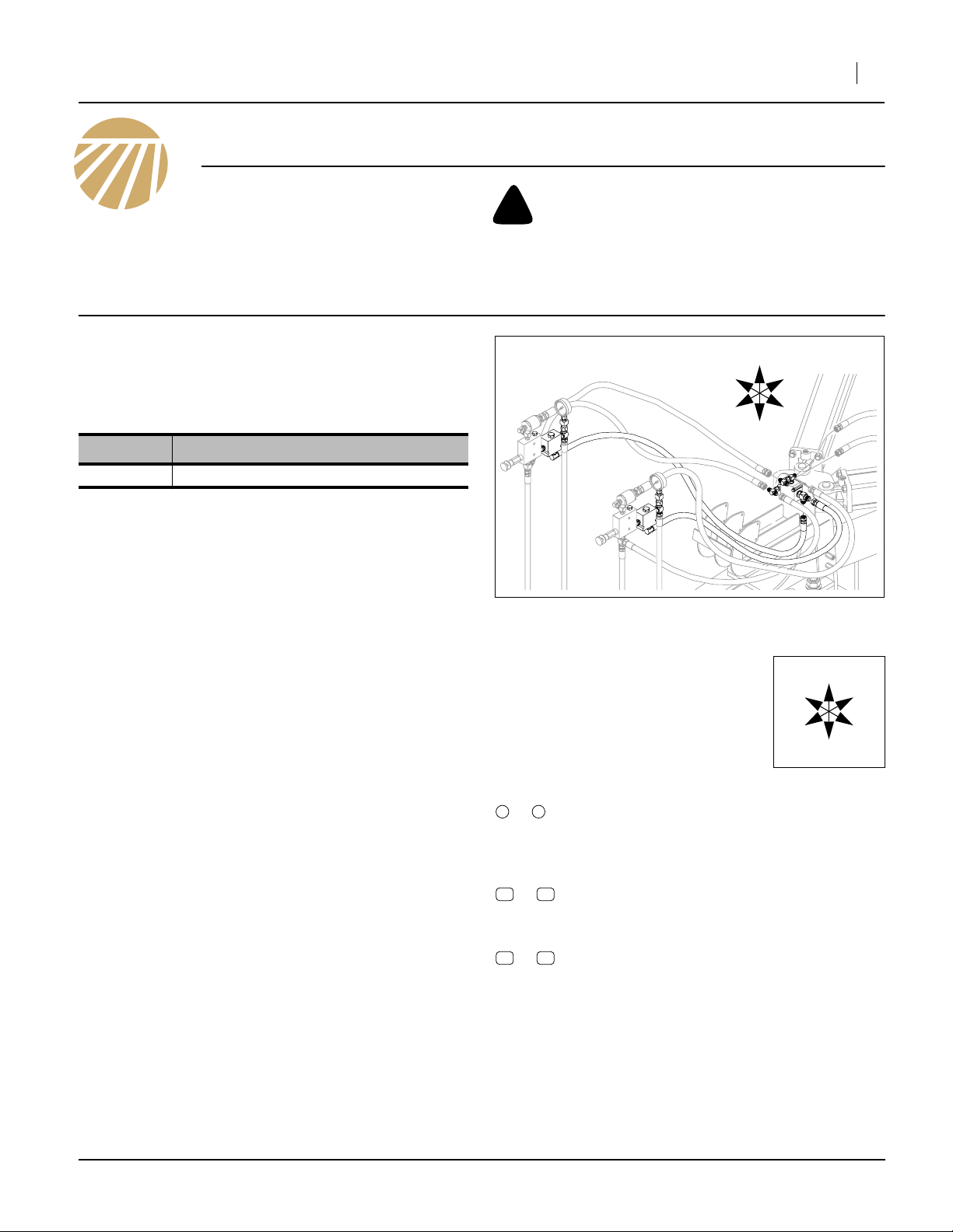
General Information
These instructions explain how to install an Open Center
Hydraulic Kit, required for operating any of these drills
with tractors having open-center hydraulics, or fixed-displacement hydraulic pumps.
These instructions apply to an installation of
Kit Kit Description
194-143A
Note: Do not install this kit on a Point Row-equipped
drill. These two options use the same mounting
locations, cannot be co-located, and this kit does
not upgrade Point Row hydraulics to open center
operation.
Each kit converts an entire drill.
Tools Required
• current Operator and Parts manuals (see page 21)
• basic hand tools,
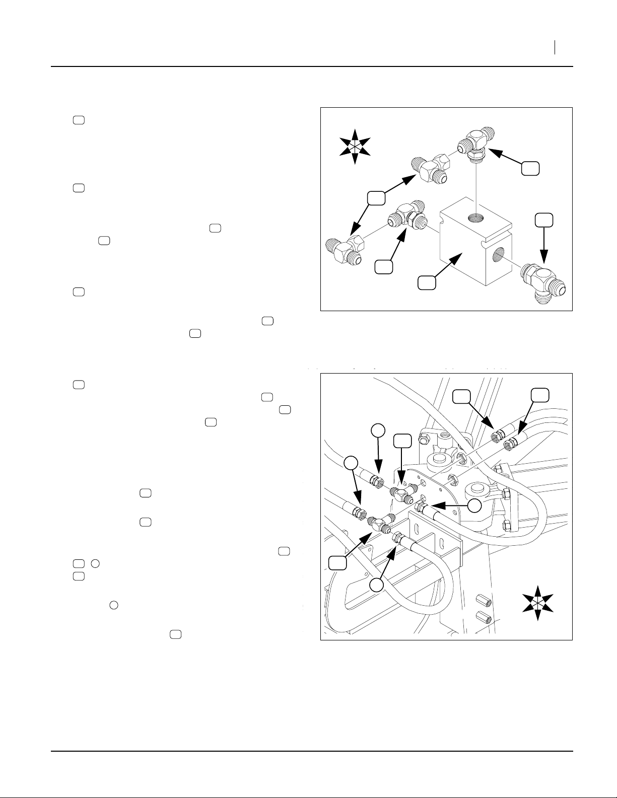
• liquid (not tape) pipe thread sealant,
• fresh hydraulic fluid, and;
• suitable tractor or hydraulic source for charging system and making initial adjustments.
Table of Contents
Installation steps vary for 2- and 3-section drills, and vary
for older vs. newer 2-section drills.
Before You Start ...........................................................2
Pre-Assembly Preparation............................................2
3S-3000 and 3S-4000 Installation ................................3
2S-2600 DD1161- Installation ......................................9
2S-2600HD and 2S-2600 DD1162+ Installation ........15
Closeout .....................................................................21
Setup ..........................................................................21
Appendix ....................................................................21
Torque Values ......................................................21
Current Manuals ..................................................21
New Parts ............................................................22
Existing Parts Affected.........................................23
Abbreviations .......................................................23
2600 3000 4000 OPEN-CTR HYDKIT
When you see this symbol, the subsequent instructions
and warnings are serious - follow without exception.
!
Your life and the lives of others depend on it!
U
R
F
D
FigureSpacer
Figure 1: Parts
Kit (Black) / Existing (Gray)
Notations and Conventions
“Left” and “Right” are facing in the
direction of machine travel. An orientation rose in the line art illustrations
shows the directions of Up, Back, Left,
Down, Front and Right.
Call-Outs
1 9
to
11 24
to
51 65
to
Single-digit callouts identify components in
the currently referenced Figure or Figures.
These numbers may be reused for different
items from page to page.
Two-digit callouts in the range 11 to 24 reference new parts from the new parts lists
beginning on page 22.
Two-digit callouts in the range 51 to 65 reference affected existing parts from the table on
page 23. The descriptions match those in
your Parts Manual. The narrative and table
indicate any re-use of the parts.
B
L
R
F
27485
U
B
L
D
©Copyright 2000, 2005, 2008 Printed 09/05/2012 194-149M
Page 2
2 Open Center Hydraulic Kit
Before You Start
Review the instruction for your drill, with the following
objectives at each step:
• Documentation: Update your Operator and Parts
manuals to current editions. See page 21.
• Inventory: examine any called-for items and make
sure all parts are present.
• Comprehension: make sure you understand
where each part or assembly is installed, and
what tools are required for the task.
Pre-Assembly Preparation
Work Location
1. Move the drill to a location with:
• adequate illumination,
• suitable surface beneath (hydraulic fluid spills a
re likely during disconnection of existing hoses),
and;
• access to tractor or hydraulic power.
Great Plains Mfg., Inc.
!
WARNING
Negative tongue weight hazard. Consult Operator manual
before any unfolding or lift operations. Folding drills can have
significant negative tongue weight when unfolded and raised.
The tongue can fly up during opener lift, if using stationary
hydraulic power to operate drill. Use any parking stands provided.
Prepare Drill
2. Unfold the drill.
3. Install any parking stands provided with drill.
4. Lower the openers.
5. Block the tires.
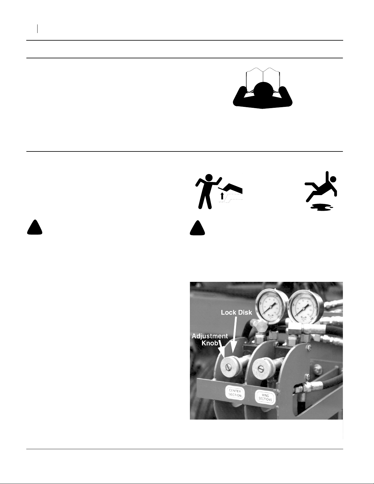
Refer to Figure 2
6. Release the pressure in the pressure control system by unlocking control disks and turning adjustment knobs fully counter-clockwise.
7. Slightly raise the openers, until pressure gauges
read zero.
8. Set the tractor or hydraulic source circuits to Float.
Do not disconnect until circuits are at 0 PSI.
9. Install the parking jack if unhitching.
10. Shut off tractor or hydraulic source.
!
CAUTION
Slipping hazard - hydraulic fluid spill is likely during disconnection of existing system and during bleeding of new system.
Clean up spills. Move carefully near removed or loosened fittings.
FigureSpacer
Figure 2
Closed Center Controls
194-149M 09/05/2012
15557
Page 3
Great Plains Mfg., Inc.
3S-3000 and 3S-4000 Installation
Step 11 through step 47 are for 3S-3000, 3S-3000HD,
3S-4000 and 3S-4000HD drills only. For 2S-2600 drills,
installation instructions begin on page 9 (s/n DD1161-) or
page 15 (2S2600HD or 2S-2600 s/n DD1162+).
3S Control Valve Disassembly
!
WARNING
High pressure fluid hazard. Pressurized fluid may still be
present. Escaping fluid under pressure can penetrate the skin,
causing serious injury. Wear protective gloves and safety
glasses or goggles when working with hydraulic systems.
Crack fitting slowly. Use a piece of paper or cardboard, NOT
BODY PARTS, to check for suspected leaks. If an accident
occurs, seek immediate medical assistance from a physician
familiar with this type of injury.
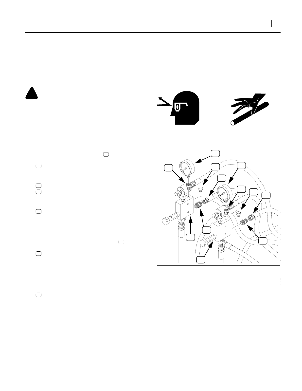
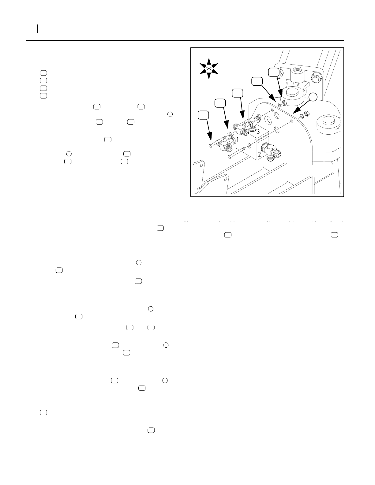
Refer to Figure 3
11. At each pressure control valve , remove and
save:
51
810-300C PRESSURE GAUGE 3000 PSI
These gauges are re-installed at step 23.
12. At the top rear Port G of each pressure control valve
52
, remove:
63
811-677C AD 9/16MORB 1/4FNPT
These two adaptors are not re-used.
13. Select two new:
24
811-675C PL 9/16MORB HEX HEAD
Install these plugs in the top rear valve holes previously occupied by the gauge adaptor. Tighten to
9/16ORB specification (see page 21). Do not use
pipe thread sealant on these, or any ORB fittings.
14. At the rear lower Port R of each valve , disconnect the hose to the cylinder base ends:
65
811-774C HH3/8R1 072 9/16FJIC
These hoses are re-connected to new fittings at
step 22. Note which hose is which (by where it is
routed to), so that it can be reconnected to the correct (same) valve assembly after the new valves
and fittings are installed.
15. Remove two:
56
811-170C AD 9/16MORB 9/16MJIC
These adaptors are not re-used.
52
52
FigureSpacer
63
P
T
3S-3000 and 3S-4000 Installation 3
51
1200
psi
1800
600
2400
0
3000
24
51
65
1200
psi
1800
G
600
0
R
63
2400
3000
G
P
56
R
52
T
52
Figure 3
Disassemble 3S Valves
ERS
NERS
S
S
24
65
56
16302
09/05/2012 194-149M
Page 4
4 Open Center Hydraulic Kit
3S Check Valve Installation
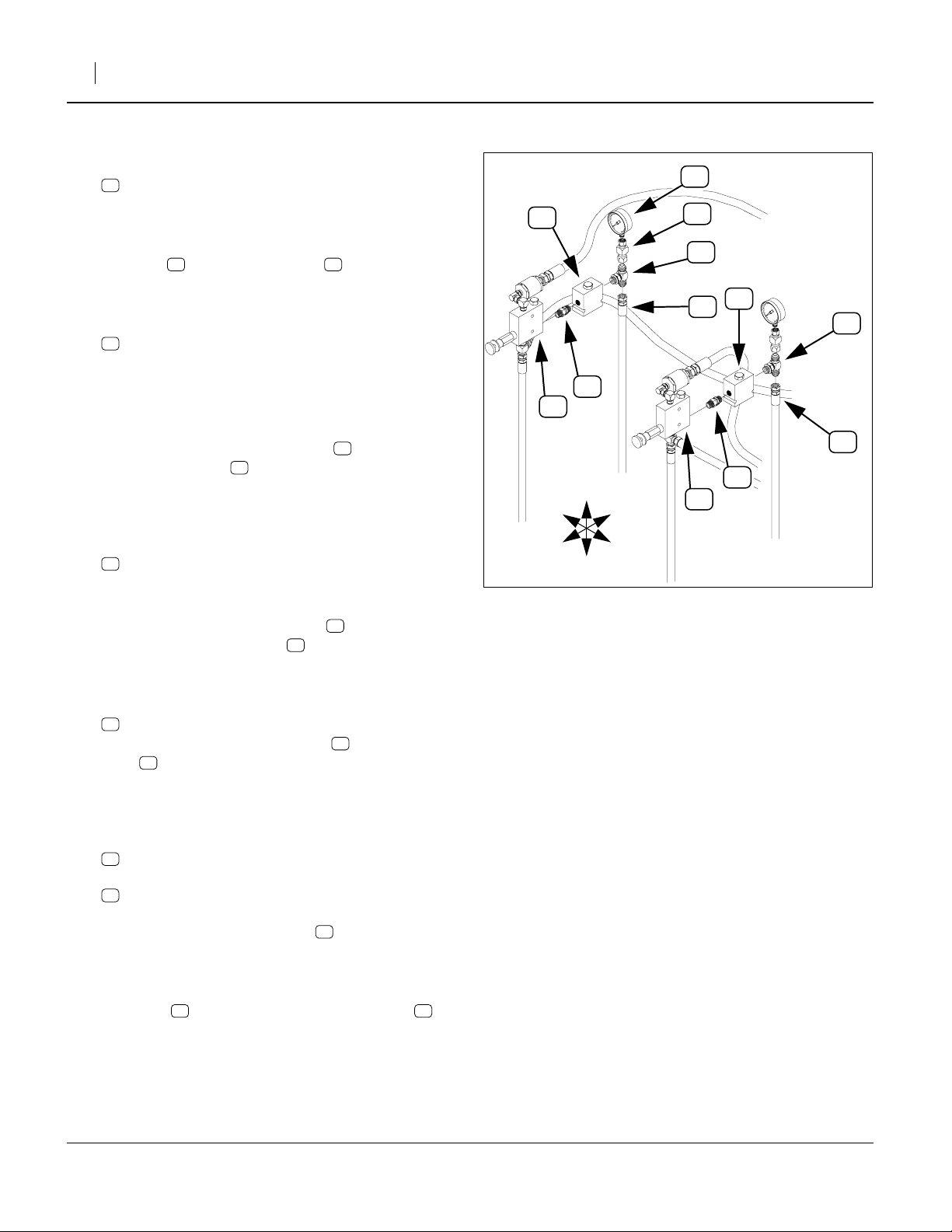
Refer to Figure 4
16. Select two new:
23
811-636C AD 9/16MORB STRAIGHT UNION
Make sure the jam nut is fully threaded onto the
adaptor.
17. At the lower rear valve Port R of each pressure control valve , screw in the union end with the
integral hex nut (NOT the end with the jam nut).
Tighten to 9/16ORB specification.
18. Select two new:
16
810-343C VALVE PO CHECK 2:1 W/9/16FORB
Note: These valves are stamped 85050146, and if
shaken gently, do not rattle.
(The third valve, assembled at step 25, is a shuttle
valve, and does rattle.)
19. Screw Port 2 of each check valve onto the other
end of the adaptor installed at step 17. Turn until
finger tight, then back off until the side of the valve
with the hex head cartridge is Up and Port 3 is
down. Tighten the jam nut to 9/16ORB specification.
20. Select two new:
20
811-439C TE 9/16MORB 9/16MJIC 9/16MJIC
This is the symmetrical MJIC/MORB tee. There are
four of these in the kit.
21. Screw the MORB port of the tee into the rear
Port 1 of each check valve . Screw until finger
tight, then back off until the JIC ports are vertical.
Tighten the ORB jam nut to 9/16ORB specification.
22. Locate the disconnected hoses:
65
811-774C HH3/8R1 072 9/16FJIC
At the lower port of each new tee , reconnect the
hose to the cylinder base ends that was discon-
nected at step 14. Do not use pipe thread sealant
on these or any JIC fittings. Tighten to 9/16JIC
specification (see page 21).
23. Select two new NPT swivel adaptors:
22
811-582C AD 9/16FJIC 1/4FNPT
and the saved gauges:
51
810-300C PRESSURE GAUGE 3000 PSI
Apply liquid pipe thread sealant to the gauge MNPT
threads and screw the adaptor onto the gauge.
Tighten to 1/4NPT torque specification (see
page 21).
24. At each valve, screw the JIC end of the gauge
assembly onto the top port of the new tee .
Orient the gauge to face forward, and tighten the
JIC connection to JIC torque specification.
52 23
16
23
20
16
20
65
22
22 20
16
P
T
ROD END, CENTER OPENERS
FigureSpacer
G
R
52
R
F
51
1200
psi
1800
600
2400
0
3000
22
20
1
2
3
23
BASE END, CENTER OPENERS
U
B
L
D
Install 3S Check Valves
65
G
P
R
T
52
ROD END, WING OPENERS
Figure 4
Great Plains Mfg., Inc.
16
1200
psi
1800
600
2400
0
3000
1
2
3
23
BASE END, WING OPENERS
16303
20
65
194-149M 09/05/2012
Page 5
Great Plains Mfg., Inc.
3S Shuttle Valve Assembly
Refer to Figure 5
25. Select one new:
17
810-344C VALVE SHUTTLE 9/16FORB PORTS
Note: This valve is stamped
shuttle rattles if the valve shaken gently. When
mounted on the drill, Port 1 will be to drill Right.
26. Select one new:
18
811-064C TE 9/16MJIC 9/16MJIC 9/16MORB
This is the asymmetrical MJIC/MORB tee. There is
only one of these in the kit.
27. Screw the ORB end of the tee into Port 2 of the
17
valve . Orient the center JIC port of the tee down,
and tighten the ORB jam nut to ORB torque specification.
28. Select two new:
20
811-439C TE 9/16MORB 9/16MJIC 9/16MJIC
This is the symmetrical MJIC/MORB tee.
29. Screw the center ORB ports of these tees into
Ports 1 and 3 of the valve . Orient the end JIC
ports to point Front and Back, and tighten the ORB
jam nut to ORB torque specification.
30. Select two new:
19
811-193C TE 9/16FJIC 9/16MJIC 9/16MJIC
Screw the center FJIC ports of these tees onto
the Front-facing ports of the just installed tees .
Orient the MJIC ports of tees to point Left and
Right, and torque to JIC specification. Set valve
aside until step 37.
85005468, and the internal
18
20
17
19
20
19
R
F
FigureSpacer
U
D
3S-3000 and 3S-4000 Installation 5
B
L
19
3
1
2
20
17
Figure 5
Assemble 3S Shuttle Valve
58
4
60
20
18
18742
59
3S Shuttle Bulkhead Disassembly
Refer to Figure 6
31. Mark the hose connected to the center port of
the top tee “Lower”.
32. Mark the hose connected to the center port of
the bottom tee “Raise”.
33. At their FJIC fittings, disconnect all six hoses ( ,
59 4
, ) at the two bulkhead tees:
60
811-312C TE 9/16MJIC
Note: It is not necessary to identify the forward four
hoses . They are identified by length and source
when reconnected.
34. Remove the two tees . They are not re-used.
58
59
58
4
60
60
FigureSpacer
4
4
Figure 6
Remove Old 3S Bulkhead Tees
4
U
R
F
B
L
D
18743
09/05/2012 194-149M
Page 6
6 Open Center Hydraulic Kit
Great Plains Mfg., Inc.
3S Shuttle Valve Installation
Refer to Figure 7
35. Select two sets of:
12
802-551C HHCS 1/4-20X2 1/4 GR5
15
804-075C WASHER FLAT 1/4 USS PLT
14
804-006C WASHER LOCK SPRING 1/4 PLT
13
803-006C NUT HEX 1/4-20 PLT
36. Place a flat washer on each bolt , and insert
the bolts through the top holes of the bulkhead .
Place a lock washer and nut on the end of
15 12
4
14 13
the the threads. Spin the nut on just a few turns.
37. Select the shuttle valve assembled at step 25.
17
With Port 1 to drill Right, place the valve against the
bulkhead between the bolts and under the
washers . Tighten the nuts to torque specifi-
412
15 13
cations.
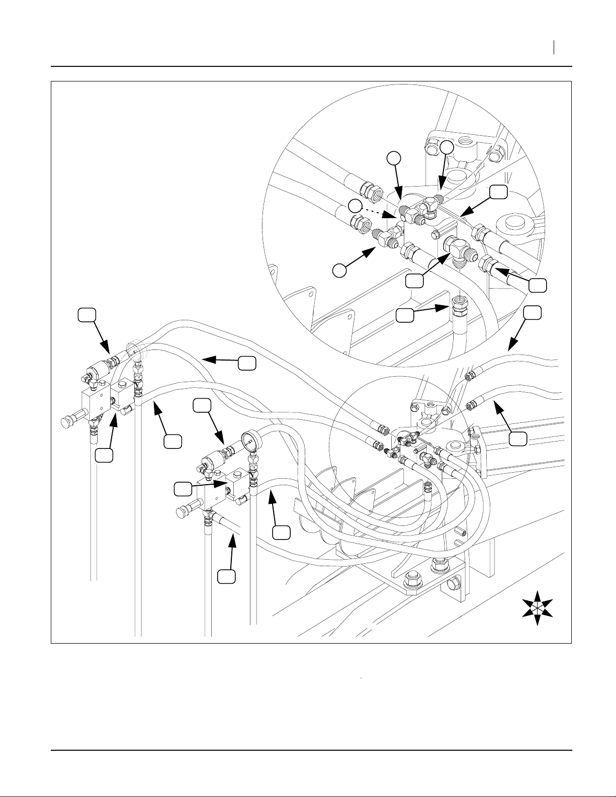
3S Shuttle Valve Hoses
Step 38 through step 42 re-connect the hoses disconnected at step 31.
Refer to Figure 8 on page 7
38. Identify the two existing 20in or 21in hoses connected to the top Ports P of the pressure control
valves.
Re-connect the other end of these hoses to the left
and right ports of the top swivel tee at the shuttle
17
valve Port 3.
5
57
U
D
B
L
17
13
14
4
R
F
15
12
FigureSpacer
Figure 7
Install 3S Shuttle Valve
45. Route the JIC end of each hose to the JIC ports of
the tee at the left Port 2 of the shuttle valve .
18 17
46. Tighten all hose connections to torque specifications.
47. Continue at “Closeout” on page 21.
18749
39. Identify the two existing 18in hoses connected to
62
the bottom Port T tee of the pressure control valves.
Re-connect the other end of these hoses to the lateral ports of the right forward swivel tee at the
shuttle valve Port 1.
40. Identify the tractor circuit hoses and marked
17
58 59
6
at step 31.
41. Connect the “Lower” hose to the rear port of
the top tee at the shuttle valve Port 3.
58 7
17
Note: If the drill is equipped with a filter, this is the hose
connected from the filter.
42. Connect the “Raise” hose to the rear port of
the right side tee at the shuttle valve Port 1. This
59 8
17
port is not visible in the Figure.
43. Select two new:
21
811-531C HH1/4R2 018 9/16FJIC9/16MORB90
44. Connect the 90 degree ORB end of these hoses to
the bottom Port (3) of each check valve .
194-149M 09/05/2012
16
Page 7
Great Plains Mfg., Inc.
FigureSpacer
3S-3000 and 3S-4000 Installation 7
7
5
17
8
3
1
2
6
18
21
57
1200
psi
1800
600
2400
0
3000
G
P
1
2
R
T
3
16
BASE END, CENTER OPENERS
ROD END, CENTER OPENERS
21
16
57
P
21
LOWER
58
FILTER
62
TO TRACTOR
RAISE
1200
psi
1800
600
2400
0
3000
3
1
2
G
1
2
R
T
3
59
21
62
R
U
B
ROD END WING OPENERS
BASE END, WING OPENERS
FigureSpacer
Figure 8
F
L
D
18750
3S Shuttle Valve Hose Routing
09/05/2012 194-149M
Page 8
8 Open Center Hydraulic Kit
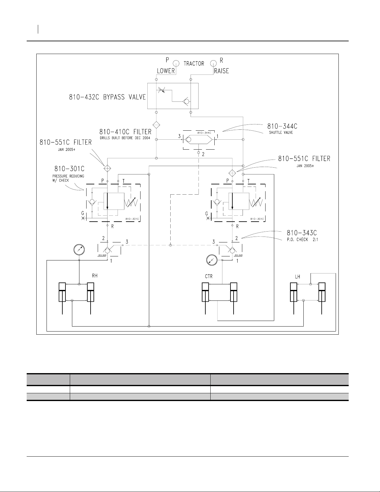
3S-3000 and 3S-4000 Hydraulic Schematic
Great Plains Mfg., Inc.
FigureSpacer
Figure 9
18759
3S Hydraulics
3S Drill Vintages
Drills built in December 2004 and Earlier Drills Built in January 2005 or Later
3S-3000 s/n S1699- s/n S1700+
3S-4000 s/n YY1310- s/n YY1131+
194-149M 09/05/2012
Page 9

Great Plains Mfg., Inc.
2S-2600 DD1161- Installation
2S-2600 DD1161- Installation 9
Step 48 through step 87 are for 2S-2600 drills serial
number 1161 or lower. For 2S-2600 drills serial number
DD1162 and higher, installation instructions begin on
page 15. For 3S-3000 and 3S-4000 drills, installation
instructions begin on page 3.
2S DD1161- Control Valve Disassembly
!
WARNING
High pressure fluid hazard. Pressurized fluid may still be
present. Escaping fluid under pressure can penetrate the skin,
causing serious injury. Wear protective gloves and safety
glasses or goggles when working with hydraulic systems.
Crack fitting slowly. Use a piece of paper or cardboard, NOT
BODY PARTS, to check for suspected leaks. If an accident
occurs, seek immediate medical assistance from a physician
familiar with this type of injury.
Refer to Figure 10
48. At each pressure control valve , remove and
save:
51
810-300C PRESSURE GAUGE 3000 PSI
These gauges are re-installed at step 60.
49. At the top rear Port G of each pressure control valve
52
, remove:
63
811-677C AD 9/16MORB 1/4FNPT
These two adaptors are not re-used.
50. Select two new:
24
811-675C PL 9/16MORB HEX HEAD
Install these plugs in the top rear valve holes previously occupied by the gauge adaptor. Tighten to
9/16ORB specification (see page 21). Do not use
pipe thread sealant on these, or any ORB fittings.
51. At the rear lower Port R of each valve , disconnect the hose to the cylinder base ends:
61
811-587C HH3/8R1 092 9/16FJIC
These hoses are re-connected to new fittings at
step 59. Note which hose is which (by where it is
routed to), so that it can be reconnected to the correct (same) valve assembly after the new valves
and fittings are installed.
52. Remove two:
56
811-170C AD 9/16MORB 9/16MJIC
These adaptors are not re-used.
52
52
No 2S-2600HD models are DD1161-. DD1161- drills
have a pilot operated check valve ( in the Affected
53
Parts list on page 23), under the Center valve, for opener
lock up. 2S-2600HD and DD1162+ drills have a counter-
balance valve (Affected Part ).
54
51
24
600
63
52
P
CENTER
2
56
53
FigureSpacer
Disassemble 2S DD1161- Valves
END, CENTER OPENERS
1200
psi
1800
2400
0
3000
T
1
G
R
WING
3
Figure 10
56
61
P
T
52
1200
600
0
ERS
51
24
psi
1800
2400
3000
61
63
G
R
56
18760
09/05/2012 194-149M
Page 10

10 Open Center Hydraulic Kit
2S DD1161- Check Valve Installation
Refer to Figure 11
53. Select two new:
23
811-636C AD 9/16MORB STRAIGHT UNION
Make sure the jam nut is fully threaded onto the
adaptor.
54. At the lower rear valve Port R of each pressure control valve , screw in the union end with the
integral hex nut (NOT the end with the jam nut).
Tighten to 9/16ORB specification.
55. Select two new:
16
810-343C VALVE PO CHECK 2:1 W/9/16FORB
Note: These valves are stamped 85050146, and if
shaken gently, do not rattle.
(The third valve, assembled at step 62, is a shuttle
valve, and does rattle.)
56. Screw Port 2 of each check valve onto the other
end of the adaptor installed at step 54. Turn until
finger tight, then back off until the side of the valve
with the hex head cartridge is Up and Port 3 is
down. Tighten the jam nut to 9/16ORB specification.
57. Select two new:
20
811-439C TE 9/16MORB 9/16MJIC 9/16MJIC
This is the symmetrical MJIC/MORB tee. There are
four of these in the kit.
58. Screw the MORB port of the tee into the rear
Port 1 of each check valve . Screw until finger
tight, then back off until the JIC ports are vertical.
Tighten the ORB jam nut to 9/16ORB specification.
59. Locate the disconnected hoses:
61
811-587C HH3/8R1 092 9/16FJIC
At the lower port of each new tee , reconnect the
hose to the cylinder base ends that was discon-
nected at step 51. Do not use pipe thread sealant
on these or any JIC fittings. Tighten to 9/16JIC
specification (see page 21).
60. Select two new NPT swivel adaptors:
22
811-582C AD 9/16FJIC 1/4FNPT
and the saved gauges:
51
810-300C PRESSURE GAUGE 3000 PSI
Apply liquid pipe thread sealant to the gauge MNPT
threads and screw the adaptor onto the gauge.
Tighten to 1/4NPT torque specification (see
page 21).
61. At each valve, screw the JIC end of the gauge
assembly onto the top port of the new tee .
Orient the gauge to face forward, and tighten the
JIC connection to JIC torque specification.
52 23
16
23
20
16
20
61
22
22 20
52
P
CENTER
T
2
P.O. CHECK
U
R
ROD END, CENTER OPENERS
F
D
Install 2S DD1161- Check Valves
23
1
Great Plains Mfg., Inc.
51
16
1200
psi
1800
600
2400
0
3000
22
51
20
23
22
1200
psi
1800
600
20
2
G
R
2400
0
3000
1
3
16
2
3
53
1
WING
BASE END, CENTER OPENERS
P
T
G
R
3
B
52
61
BASE END, WING OPENERS
L
ROD END, WING OPENERS
61
Figure 11
18761
194-149M 09/05/2012
Page 11

Great Plains Mfg., Inc.
2S DD1161- Shuttle Valve Assembly
Refer to Figure 12
62. Select one new:
17
810-344C VALVE SHUTTLE 9/16FORB PORTS
Note: This valve is stamped
shuttle rattles if the valve shaken gently. When
mounted on the drill, Port 1 will be to drill Right.
63. Select one new:
18
811-064C TE 9/16MJIC 9/16MJIC 9/16MORB
This is the asymmetrical MJIC/MORB tee. There is
only one of these in the kit.
64. Screw the ORB end of the tee into Port 2 of the
17
valve . Orient the center JIC port of the tee down,
and tighten the ORB jam nut to ORB torque specification.
65. Select two new:
20
811-439C TE 9/16MORB 9/16MJIC 9/16MJIC
This is the symmetrical MJIC/MORB tee.
66. Screw the center ORB ports of these tees into
Ports 1 and 3 of the valve . Orient the end JIC
ports to point Front and Back, and tighten the ORB
jam nut to ORB torque specification.
67. Select two new:
19
811-193C TE 9/16FJIC 9/16MJIC 9/16MJIC
Screw the center FJIC ports of these tees onto
the Front-facing ports of the just installed tees .
Orient the MJIC ports of tees to point Left and
Right, and torque to JIC specification. Set valve
aside until step 73.
85005468, and the internal
18
20
17
19
20
19
2S DD1161- Bulkhead Disassembly
Refer to Figure 13
68. Mark the hose connected to the center port of
the top tee “Lower”.
58
R
F
FigureSpacer
U
D
5
2S-2600 DD1161- Installation 11
55
B
L
19
1
20
17
Figure 12 Assemble
2S DD1161- Shuttle Valve
5
55
60
3
58
20
18
2
18777
59
69. Mark the hose connected to the center port of
the bottom tee “Raise”.
70. At their FJIC fittings, disconnect all seven hoses
58 59 5
( , , ) at the two bulkhead tees:
60
811-312C TE 9/16MJIC
Note: It is not necessary to identify the forward five
hoses . They are identified by length and source
when reconnected.
71. Remove the tee with one Female port:
55
811-061C TE 9/16MJIC 9/16MJIC 9/16FJIC
72. Remove the two all-Male tees . They are not reused.
Refer to Figure 12
73. Attach this tee to the right end of the top forward
Port 3 tee on the shuttle valve .
09/05/2012 194-149M
59
5
5
5
60
5
R
F
U
B
L
D
60
55
17
FigureSpacer
Figure 13 Remove Old
2S DD1161- Bulkhead Tees
18776
Page 12

12 Open Center Hydraulic Kit
Great Plains Mfg., Inc.
2S DD1161- Shuttle Valve Installation
Refer to Figure 14
74. Select two sets of:
12
802-551C HHCS 1/4-20X2 1/4 GR5
15
804-075C WASHER FLAT 1/4 USS PLT
14
804-006C WASHER LOCK SPRING 1/4 PLT
13
803-006C NUT HEX 1/4-20 PLT
75. Place a flat washer on each bolt , and insert
the bolts through the top holes of the bulkhead .
Place a lock washer and nut on the end of
15 12
4
14 13
the the threads. Spin the nut on just a few turns.
76. Select the shuttle valve assembled at step 62.
17
With Port 1 to drill Right, place the valve against the
bulkhead between the bolts and under the
washers . Tighten the nuts to torque specifi-
412
15 13
cations.
2S DD1161- Shuttle Valve Hoses
Step 77 through step 82 re-connect the hoses disconnected at step 70.
Refer to Figure 15 on page 13
77. Identify the two existing 20in or 21in hoses connected to the top Ports P of the pressure control
valves.
57
R
F
12
FigureSpacer
U
B
L
D
13
14
17
15
3
1
2
Figure 14
Install 2S DD1161- Shuttle Valve
4
18774
Re-connect the other end of these hoses to the left
and right ports of the top tee assembly at the
shuttle valve Port 3.
78. Identify the 18in hose connected to the rear Port
17
62
3 of the previously existing P.O.Check valve .
5
53
Connect the free end of this hose to the forward facing port of the top tee assembly at the shuttle
17
valve Port 3.
79. Identify the two existing 18in hoses connected to
5
62
the bottom Port T of each pressure control valves.
Re-connect the free end of these hoses to the lateral ports of the right forward swivel tee at the
shuttle valve Port 1.
80. Identify the tractor circuit hoses and marked
17
58 59
6
at step 68.
81. Connect the “Lower” hose to the rear port of
the top tee at the shuttle valve Port 3.
58 7
17
Note: If the drill is equipped with a filter, this is the hose
connected from the filter.
82. Connect the “Raise” hose to the rear port of
the right side tee at the shuttle valve Port 1. This
59 8
17
port is not visible in the Figure.
83. Select two new:
21
811-531C HH1/4R2 018 9/16FJIC9/16MORB90
84. Connect the 90 degree ORB end of these hoses to
the bottom Port 3 of each check valve .
16
85. Route the JIC end of each hose to the JIC ports of
the tee at the left Port 2 of the shuttle valve .
18 17
86. Tighten all hose connections to torque specifications.
87. Skip to “Closeout” on page 21.
194-149M 09/05/2012
Page 13

Great Plains Mfg., Inc.
FigureSpacer
2S-2600 DD1161- Installation 13
58
53
CENTER
P.O. CHECK
ROD END, CENTER OPENERS
16
P
T
2
57
62
57
1200
psi
1800
600
2400
0
3000
1
G
2
R
3
3
16
1
WING
21
62
1200
psi
1800
600
2400
0
3000
G
1
P
2
R
3
T
6
62
8
59
5
3
1
2
7
18
57
21
62
LOWE R
3
1
2
17
FILTER
TO TRACTOR
RAISE
21
58
59
57
21
62
BASE END, CENTER OPENERS
ROD END, WING OPENERS
BASE END, WING OPENERS
U
R
F
B
L
D
Figure 15
2S DD1161- Shuttle Valve Hose Routing
09/05/2012 194-149M
18762
Page 14

14 Open Center Hydraulic Kit
2S-2600 DD1161- Hydraulic Schematic
Great Plains Mfg., Inc.
FigureSpacer
Figure 16
18763
2S DD1161- Hydraulics
194-149M 09/05/2012
Page 15

Great Plains Mfg., Inc.
2S-2600HD and 2S-2600 DD1162+ Installation 15
2S-2600HD and 2S-2600 DD1162+ Installation
Step 88 through step 129 are for 2S-2600 drills serial
number 1162 or higher. For 2S-2600 drills serial number
DD1161 and lower, installation instructions begin on
page 9. For 3S-3000 and 3S-4000 drills, installation
instructions begin on page 3.
2S DD1162+ Control Valve Disassembly
!
WARNING
High pressure fluid hazard. Pressurized fluid may still be
present. Escaping fluid under pressure can penetrate the skin,
causing serious injury. Wear protective gloves and safety
glasses or goggles when working with hydraulic systems.
Crack fitting slowly. Use a piece of paper or cardboard, NOT
BODY PARTS, to check for suspected leaks. If an accident
occurs, seek immediate medical assistance from a physician
familiar with this type of injury.
Refer to Figure 17
88. At each pressure control valve , remove and
save:
51
810-300C PRESSURE GAUGE 3000 PSI
These gauges are re-installed at step 104.
89. At the top rear Port G of each pressure control valve
52
, remove:
63
811-677C AD 9/16MORB 1/4FNPT
These two adaptors are not re-used.
90. Select two new:
24
811-675C PL 9/16MORB HEX HEAD
Install these plugs in the top rear valve holes previously occupied by the gauge adaptor. Tighten to
9/16ORB specification (see page 21). Do not use
pipe thread sealant on these, or any ORB fittings.
91. At the rear lower Port R of each valve , disconnect the hose to the cylinder base ends:
61
811-587C HH3/8R1 092 9/16FJIC
These hoses are re-connected to new fittings at
step 102. Note which hose is which (by where it is
routed to), so that it can be reconnected to the correct (same) valve assembly after the new valves
and fittings are installed.
92. At the tee:
55
811-061C TE 9/16MJIC 9/16MJIC 9/16FJIC
Identify the hose:
62
811-631C HH3/8R1 018 9/16FJIC
from Port 3 of counterbalance valve . Disconnect
the hose at tee . Remove and save the tee. It is
60
re-installed at step 100.
93. Remove two:
56
811-170C AD 9/16MORB 9/16MJIC
These adaptors are not re-used.
52
52
54
DD1162+ drills (which includes all 2S-2600HD models)
have a counterbalance valve ( in the Affected Parts list
54
on page 23), under the Center valve, for opener lock up.
DD1161- drills have a counterbalance valve (Affected
53
Par t ).
51
51
1200
600
0
63
psi
1800
2400
3000
G
P
R
61
24
55
52
63
CENTER
1200
psi
1800
600
24
2400
0
3000
61
G
P
R
T
2
1
56
WING
3
T
56
52
54
FigureSpacer
ROD END, CENTER OPENERS
Disassemble 2S DD1162+ Valves
Figure 17
ROD END, WING OPENERS
62
22687
09/05/2012 194-149M
Page 16

16 Open Center Hydraulic Kit
2S DD1162+ Check Valve Installation
Refer to Figure 18
94. Select two new:
23
811-636C AD 9/16MORB STRAIGHT UNION
Make sure the jam nut is fully threaded onto the
adaptor.
95. At the lower rear valve Port R of each pressure control valve , screw in the union end with the
integral hex nut (NOT the end with the jam nut).
Tighten to 9/16ORB specification.
96. Select two new:
16
810-343C VALVE PO CHECK 2:1 W/9/16FORB
Note: These valves are stamped 85050146, and if
shaken gently, do not rattle.
(The third valve, assembled at step 106, is a shuttle valve, and does rattle.)
97. Screw Port 2 of each check valve onto the other
end of the adaptor installed at step 95. Turn until
finger tight, then back off until the side of the valve
with the hex head cartridge is Up and Port 3 is
down. Tighten the jam nut to 9/16ORB specification.
98. Select two new:
20
811-439C TE 9/16MORB 9/16MJIC 9/16MJIC
This is the symmetrical MJIC/MORB tee. There are
four of these in the kit.
99. Screw the MORB port of the tee into the rear
Port 1 of each check valve . Screw until finger
tight, then back off until the JIC ports are vertical.
Tighten the ORB jam nut to 9/16ORB specification.
100. Select the tee saved at step 92:
55
811-061C TE 9/16MJIC 9/16MJIC 9/16FJIC
Secure it to the bottom port of the tee on the
right (Center) pressure control valve. Orient the side
port to face left. Do not use pipe thread sealant on
these or any JIC fittings. Tighten to 9/16JIC specification (see page 21)
101. Locate the disconnected hose:
62
811-631C HH3/8R1 018 9/16FJIC
Connect the free end to the bottom port of tee .
102. Locate the disconnected hose:
61
811-587C HH3/8R1 092 9/16FJIC
from the base end of the center cylinders.
Reconnect this hose to bottom port of the tee
installed at step 100 on the right/Center valve.
103. Locate the disconnected hose:
61
811-587C HH3/8R1 092 9/16FJIC
from the base end of the wing (outer) cylinders.
Reconnect this hose to bottom port of the tee
installed at step 98 at the left/Wing valve.
52 23
16
23
20
16
20
55
61 55
61 20
Great Plains Mfg., Inc.
51
55
P
T
52
22
20
G
22
22
20
R
23
51
1200
psi
1800
600
2400
0
3000
1
2
3
61
16
1200
psi
1800
600
2400
0
3000
23
52
1
2
G
CENTER
P
T
2
1
3
3
R
62
WING
54
ROD END, CENTER OPENERS
U
R
F
FigureSpacer
104. Select two new NPT swivel adaptors:
105. At each valve, screw the JIC end of the gauge
B
L
D
Install 2S DD1162+ Check Valves
22
811-582C AD 9/16FJIC 1/4FNPT
and the saved gauges:
51
810-300C PRESSURE GAUGE 3000 PSI
Apply liquid pipe thread sealant to the gauge MNPT
threads and screw the adaptor onto the gauge.
Tighten to 1/4NPT torque specification (see
page 21).
assembly onto the top port of the new tee .
Orient the gauge to face forward, and tighten the
JIC connection to JIC torque specification.
22 20
BASE END, CENTER OPENERS
ROD END, WING OPENERS
61
Figure 18
16
BASE END, WING OPENERS
27492
194-149M 09/05/2012
Page 17

Great Plains Mfg., Inc.
2S DD1162+ Shuttle Valve Assembly
Refer to Figure 19
106. Select one new:
17
810-344C VALVE SHUTTLE 9/16FORB PORTS
Note: This valve is stamped
shuttle rattles if the valve shaken gently. When
mounted on the drill, Port 1 is to drill Right.
107. Select one new:
18
811-064C TE 9/16MJIC 9/16MJIC 9/16MORB
This is the asymmetrical MJIC/MORB tee. There is
only one of these in the kit.
108. Screw the ORB end of the tee into Port 2 of the
17
valve . Orient the center JIC port of the tee down,
and tighten the ORB jam nut to ORB torque specification.
109. Select two new:
20
811-439C TE 9/16MORB 9/16MJIC 9/16MJIC
This is the symmetrical MJIC/MORB tee.
110. Screw the center ORB ports of these tees into
Ports 1 and 3 of the valve . Orient the end JIC
ports to point Front and Back, and tighten the ORB
jam nut to ORB torque specification.
111. Select two new:
19
811-193C TE 9/16FJIC 9/16MJIC 9/16MJIC
Screw the center FJIC ports of these tees onto
the Front-facing ports of the just installed tees .
Orient the MJIC ports of tees to point Left and
Right, and torque to JIC specification. Set valve
aside until step 115.
85005468, and the internal
18
20
17
19
20
19
2S-2600HD and 2S-2600 DD1162+ Installation 17
U
R
F
B
L
D
20
19
3
1
18
2
20
17
FigureSpacer
Figure 19 Assemble
2S DD1162+ Shuttle Valve
22692
58
59
2S DD1162+ Bulkhead Disassembly
Refer to Figure 20
112. Mark the hose connected to the center port of
the top tee “Lower”.
113. Mark the hose connected to the center port of
the bottom tee “Raise”.
114. At their FJIC fittings, disconnect all seven hoses
58 59 4
( , , ) at the two bulkhead tees:
60
811-312C TE 9/16MJIC
Note: It is not necessary to identify the forward four
hoses . They are identified by length and source
when reconnected.
Refer to Figure 12
115. Attach this tee to the right end of the top forward
Port 3 tee on the shuttle valve .
116. Remove the two all-Male tees . They are not reused.
58
59
4
55
17
60
FigureSpacer
4
60
4
4
60
4
R
F
U
B
L
D
Figure 20 Remove Old
2S DD1162+ Bulkhead Tees
22689
09/05/2012 194-149M
Page 18

18 Open Center Hydraulic Kit
Great Plains Mfg., Inc.
2S DD1162+ Shuttle Valve Installation
Refer to Figure 21
117. Select two sets of:
12
802-551C HHCS 1/4-20X2 1/4 GR5
15
804-075C WASHER FLAT 1/4 USS PLT
14
804-006C WASHER LOCK SPRING 1/4 PLT
13
803-006C NUT HEX 1/4-20 PLT
118. Place a flat washer on each bolt , and insert
the bolts through the top holes of the bulkhead .
Place a lock washer and nut on the end of
15 12
x
14 13
the the threads. Spin the nut on just a few turns.
119. Select the shuttle valve assembled at step 62.
17
With Port 1 to drill Right, place the valve against the
bulkhead between the bolts and under the
washers . Tighten the nuts to torque specifi-
412
15 13
cations.
2S DD1162+ Shuttle Valve Hoses
Step 77 through step 82 re-connect the hoses disconnected at step 70.
Refer to Figure 22 on page 19
120. Identify the two existing 20in or 21in hoses connected to the top Ports P of the pressure control
valves.
57
R
F
12
FigureSpacer
U
B
L
D
13
14
17
15
3
1
2
Figure 21
Install 2S DD1162+ Shuttle Valve
4
18774
Re-connect the other end of these hoses to the left
and right ports of the top tee assembly at the
shuttle valve Port 3.
17
121. Identify the two existing 18in hoses connected to
5
62
the bottom Port T of each pressure control valve.
Re-connect the free end of these hoses to the lateral ports of the right forward swivel tee at the
shuttle valve Port 1.
122. Identify the tractor circuit hoses and marked
17
58 59
6
at step 68.
123. Connect the “Lower” hose to the rear port of
the top tee at the shuttle valve Port 3.
58 7
17
Note: If the drill is equipped with a filter, this is the hose
connected from the filter.
124. Connect the “Raise” hose to the rear port of
the right side tee at the shuttle valve Port 1. This
59 8
17
port is not visible in the Figure.
125. Select two new:
21
811-531C HH1/4R2 018 9/16FJIC9/16MORB90
126. Connect the 90 degree ORB end of these hoses to
the bottom Port 3 of each check valve .
16
127. Route the JIC end of each hose to the JIC ports of
the tee at the left Port 2 of the shuttle valve .
18 17
128. Tighten all hose connections to torque specifications.
129. Skip to “Closeout” on page 21.
194-149M 09/05/2012
Page 19

Great Plains Mfg., Inc.
2S-2600HD and 2S-2600 DD1162+ Installation 19
58
CENTER
P
16
T
2
54
57
62
57
1200
psi
1800
600
2400
0
3000
1
G
2
R
3
1
3
16
WING
T
21
P
62
1200
psi
1800
600
2400
0
3000
1
G
2
R
3
6
8
59
5
3
1
2
7
18
57
21
62
LOWER
3
1
2
17
FILTER
TO TRACTOR
RAISE
21
58
59
57
21
ROD END, CENTER OPENERS
62
ROD END, WING OPENERS
BASE END, WING OPENERS
BASE END, CENTER OPENERS
R
F
U
B
L
D
FigureSpacer
Figure 22
2S DD1162+ Shuttle Valve Hose Routing
09/05/2012 194-149M
22690
Page 20

20 Open Center Hydraulic Kit
2S-2600 DD1162+ Hydraulic Schematic
Great Plains Mfg., Inc.
FigureSpacer
Figure 23
22961
2S DD1162+ Hydraulics
194-149M 09/05/2012
Page 21

Great Plains Mfg., Inc.
Closeout
130. Connect the drill to the tractor or other hydraulic
power source.
131. Perform the Opener Lift Bleeding steps from your
updated drill Operator manual.
132. Clean any excess hydraulic fluid from all new connections.
133. Remove lift locks and cycle the lift system several
times. Use a sheet of cardboard to check for leaks
at all new connections.
Setup
134. Initial setup for the opener down-pressure system is
found in the updated Operator manual. Check the
Setup, Operations and Adjustments sections. The
topic may be titled “Open Center” or “Non-Active
Hydraulic” systems.
135. Review Operations information prior to first use of
the updated drill.
136. Raise and fold the drill. Install any lift and transport
locks.
Closeout 21
Appendix
Torque Values
Fastener/Fitting Ft-Lbs N-m
1
⁄4 NPT
1
⁄4-20 GR5
9
⁄16 JIC
9
⁄16 ORB w/jam nut
9
⁄16 ORB straight
Current Manuals
Drill Model Operator Parts
2S-2600 DD1161- 195-200M-A 195-200P
2S-2600 DD1162+ 195-200M-A 195-200P
2S-2600HD 195-069M 195-069P
3S-3000 195-110M-A 195-110P
3S-3000HD 195-068M 195-068P
3S-4000 195-242M-A 195-242P
3S-4000HD 195-067M 195-067P
1.5-3.0 turns past finger tight
8 11
18-20 24-27
12-16 16-22
18-24 24-32
Connector Identification
2
3
1
1
JIC - Joint Industry Conference (SAE J514)
Note straight threads and the
37° cone on “M” fittings (or 37° flare on “F”).
4
ORB - O-Ring Boss (SAE J514)
Note the straight threads and,
elastomer O-Ring .
Fittings needing orientation, such as the ell above,
also have a washer and
jam nut (“adjustable thread port stud”)
3
8
25188
2
5
6
7
8
7
6
5
4
- NPT - National Pipe Thread (not shown)
have tapered threads, no cone/flare, no O-ring.
09/05/2012 194-149M
Page 22

22 Open Center Hydraulic Kit
New Parts
This manual covers the installation of two different holddown kits. Parts are listed for each kit separately. Quantities are units (“ea”).
Kit Contents
24
22
20
19
16
23
13
20
19
Great Plains Mfg., Inc.
The part call-out numbers in this list match all Figures in
these installation instructions. Part descriptions match
those in your updated Parts Manual.
12
15
14
13
17
18
21
FigureSpacer
Figure 24
Kit Parts ID
Callout Kit Qty Part Number Part Description
11
12
13
14
15
16
17
18
19
20
21
22
23
24
a. 1 of the 4 tees is provided for 2S drills and is not required for 3S installation.
1 194-149M
2 802-551C
2 803-006C
2 804-006C
2 804-075C
2 810-343C
1 810-344C
1 811-064C
2 811-193C
a
4
2 811-531C
2 811-582C
2 811-636C
2 811-675C
811-439C
3S-3000 OPEN-CTR HYD ASSY MAN
HHCS 1/4-20X2 1/4 GR5
NUT HEX 1/4-20 PLT
WASHER LOCK SPRING 1/4 PLT
WASHER FLAT 1/4 USS PLT
VALVE PO CHECK 2:1 W/9/16FORB
VALVE SHUTTLE 9/16FORB PORTS
TE 9/16MJIC 9/16MJIC 9/16MORB
TE 9/16FJIC 9/16MJIC 9/16MJIC
TE 9/16MORB 9/16MJIC 9/16MJIC
HH1/4R2 018 9/16FJIC9/16MORB90
AD 9/16FJIC 1/4FNPT
AD 9/16MORB STRAIGHT UNION
PL 9/16MORB HEX HEAD
27496
194-149M 09/05/2012
Page 23

Great Plains Mfg., Inc.
Appendix 23
Existing Parts Affected
The following existing parts are involved in the kit installation.
Callout Part No. Part Description Part Disposition
51
52
53
54
55
56
57
58
59
60
61
62
63
64
65
810-300C
810-301C
810-428C
811-312C
811-061C
811-170C
811-286C
811-632C
811-312C
811-587C
811-631C
811-677C
811-713C
811-774C
PRESSURE GAUGE 3000 PSI Removed and re-installed
VALVE PRESS REDUCING W/CHECK Modified in place.
VALVE PO CHECK 4:1 W/9/16FORB Left in place.
VALVE COUNTER BAL 10:1 9/16FOB Left in place.
TE 9/16MJIC 9/16MJIC 9/16FJIC Removed and re-installed.
AD 9/16MORB 9/16MJIC Removed. Not re-used.
HH3/8R2 020 3/4FJIC 9/16FJIC
HH3/8R1 021 9/16FJIC9/16MORB90
-
“Lower” hose (part varies with drill vintage) One end reconnected at new fitting.
-
“Raise” hose (part varies with drill vintage) One end reconnected at new fitting.
TE 9/16MJIC Removed. Not re-used.
HH3/8R1 092 9/16FJIC One end reconnected at new fitting.
HH3/8R1 018 9/16FJIC One end reconnected at new fitting.
AD 9/16MORB 1/4FNPT Removed. Not re-used.
HH3/8R2 147 9/16FJIC Reconnected at new fittings.
HH3/8R1 072 9/16FJIC Reconnected at new fittings.
The Disposition column indicates whether the part is left
in place, moved or not re-used.
One end reconnected at new fitting.
Abbreviations
AD
BRG
BRKT
CTR
DD
DEG
FLG
GA
GR5
HEX
HH
HHCS
HLD
HSG
HYD
JIC
MACH
MAN
Adaptor
Bearing
Bracket
Center
Double Disk
Degree
Flanged
Gauge
Grade 5
Hexagonal
Hydraulic Hose
Hex Head Cap Screw (Bolt)
Hold
Housing
Hydraulic
Joint Industry Conference (Female/Male)
Machine
Manual
MM
MTG
NPT
NYL
OPNR
ORB
ORB90
PL
PLT
PO
PRESS
RHSNB
RIBB
SAE
TE
USS
W/
Millimeter
Mounting
National Pipe Thread (Female/Male)
Nylock
Opener
O-Ring Boss (Female/Male)
ORB on 90 degree elbow
Plug
Plated
Pilot Operated
Pressure
Round Head Shank Neck Bolt
Ribbed
Society of Automotive Engineers (standards)
Te e
United States Standard (heavy duty standard)
With
09/05/2012 194-149M
Page 24

24 Open Center Hydraulic Kit
EOD
Great Plains Mfg., Inc.
Great Plains Manufacturing, Inc.
Corporate Office P.O. Box 5060
Salina, Kansas 67402-5060 USA
194-149M 09/05/2012
 Loading...