

Page 1
Table of Contents Index
3-Point 40-Foot Yield-Pro® Planter
Pre-Delivery
3PYPA
with Air-Pro
Manufacturing, Inc.
www.greatplainsmfg.com
®
Seed Meters
Read the operator manual entirely. When you see this symbol, the
subsequent instructions and warnings are serious - follow without
exception. Your life and the lives of others depend on it!
29852
Illustrations may show optional equipment not supplied with standard unit,
or may show similar 3PYP models and their options.
ORIGINAL INSTRUCTIONS
© Copyright 2012 Printed 2012-08-08 401-647Q
Table of Contents Index
EN
Page 2

Table of Contents Index
Table of Contents Index
Page 3

Great Plains Manufacturing, Inc. Cover Index iii
Table of Contents
Important Safety Information ...................................... 1
Introduction ..................................................................5
Models Covered ............................................................. 5
Description of Unit ..........................................................5
Compatible Tractors ...................................................5
Using This Manual..........................................................6
What’s On The Truck .....................................................6
Shipment Inventory ........................................................7
Assembly and Setup Assistance ....................................8
Plan The Mainframe Unload ........................................ 9
Use a Hoist or One to Four Lifters.............................. 9
Location Requirements ..................................................9
Wings: No Lift - No Hoist ..............................................10
Hoist Lifting...................................................................10
Three Hoist Points....................................................10
Four Hoist Points......................................................11
Fork Lifting....................................................................11
Single-Lift Points ......................................................11
Two Lift Points..........................................................12
Three Lift Points .......................................................13
Four Lift Points .........................................................14
Unloading....................................................................15
Unload Smaller Items First ...........................................15
Unload the Seed Frame ...........................................15
Unload The Mainframe.................................................16
Planter Assembly ....................................................... 20
Press Wheel Shipping ..................................................20
Shipping Stands ........................................................... 20
Prepare Parallel Arms .................................................. 21
Mount Seed Box Frame ...............................................22
Seed Cart Self-Lift ....................................................23
Remove Cart Shipping Stands .................................23
Install Casters...............................................................23
Caster Arms..............................................................23
Install Left and Right Caster Arms............................ 24
Install Caster Wheels................................................24
Adjust Steering Tie Rod............................................25
Lower Seed Box Structure........................................26
Remove Hopper (Option) .........................................26
Connect Steering Hoses ..............................................27
Route Steering Sensor Lead ........................................27
Route Lighting/Seed Box Leads...................................28
Adjust Air Box Pads......................................................28
Connect Seed Hose Rack ............................................29
Seed Hose Routing...................................................... 31
Port Identification: “12 Port” ..................................... 31
Port Assignments: 12, 23 and 24-Row..................... 31
Port Identification: “16 Port” ..................................... 32
Port Assignments: 16, 31 and 32-Row..................... 32
Connect Seed Hoses ................................................... 33
Connect Hoses at Air Box Manifold ......................... 33
Connect Hoses at Wing Tubes ................................ 33
Connect Air Box Inlet Hose ...................................... 34
Install Lower Walkboard Step ...................................... 35
Install Press Wheel Assemblies................................... 36
Install Row Unit Side Wheels....................................... 37
Hopper Installation ....................................................... 37
Hopper Level Sensor Installation ............................. 38
Row Unit Options ......................................................... 38
Planter Closeout .......................................................... 39
Emergency Moves Without Steering........................39
Force Caster Float ............................................... 39
Console Installation................................................... 40
Seed Monitor Console Installation ............................... 40
Tractor Steering ......................................................... 41
Install Switchbox .......................................................... 41
Install GP Linear Sensor .............................................. 42
Assemble Tractor Sensor......................................... 43
Install Tractor Steering Sensor................................. 43
Case IH® MX/Magnum™ Installation....................... 44
John Deere® 8000 (RFS) Installation....................... 46
John Deere® 8000 ILS Installation........................... 48
Install Harness for Linear Sensor.............................50
Install Electronic Module .............................................. 51
Install Gray Module Harness........................................ 52
ISObus Compatible Connection................................... 53
John Deere® R-Series ISObus ................................ 53
John Deere® 8000 Series ISObus ........................... 53
Install Harness for Native Steering Sensor .................. 54
Case or New Holland Native Sensor Harness ......... 55
John Deere® Tracked Native Sensor Harness ........ 56
John Deere® Wheeled Native Sensor Harness ....... 57
Install Module Output Harness..................................... 58
Steering Calibration ..................................................... 59
Steering System Hydraulic Bleeding........................59
Calibration ................................................................ 59
Steering Configuration Switch..................................59
Wheel Sensor Calibration ........................................ 60
Wheel Tractors and Alternate Method for Tracked
© Copyright 2006, 2007, 2008, 2009, 2010, 2011, 2012 All rights Reserved
Great Plains Manufacturing, Inc. provides this publication “as is” without warranty of any kind, either expressed or implied. While every precaution has been
taken in the preparation of this manual, Great Plains Manufacturing, Inc. assumes no responsibility for errors or omissions. Neither is any liability assumed for
damages resulting from the use of the information contained herein. Great Plains Manufacturing, Inc. reserves the right to revise and improve its products as
it sees fit. This publication describes the state of this product at the time of its publication, and may not reflect the product in the future.
2012-08-08 Cover Index 195-325M
Trademarks of Great Plains Manufacturing, Inc. include: Singulator Plus, Swath Command, Terra-Tine.
Registered Trademarks of Great Plains Manufacturing, Inc. include:
Air-Pro, Clear-Shot, Discovator, Great Plains, Land Pride, MeterCone, Nutri-Pro, Seed-Lok, Solid Stand,
Terra-Guard, Turbo-Chisel, Turbo-Chopper, Turbo Max, Turbo-Till, Ultra-Till, Ver ti-Till, Whirlfilter, Yield-Pro.
Brand and Product Names that appear and are owned by others are trademarks of their respective owners.
Printed in the United States of America
Page 4

iv 3PYPA Table of Contents Index Great Plains Manufacturing, Inc.
Tractors ............................................................ 60
Steering Troubleshooting............................................. 61
Steering Flash Error Codes ..................................... 63
Appendix A - Reference Information........................ 64
Specifications and Capacities, 1 of 2 ........................... 64
Tire Inflation Chart ....................................................... 65
Torque Values Chart ....................................................66
Hydraulic Diagrams ......................................................67
Chain Routing...............................................................74
Index ............................................................................79
195-325M Table of Contents Index 2012-08-08
Page 5
Great Plains Manufacturing, Inc. Table of Contents Index 1
Important Safety Information
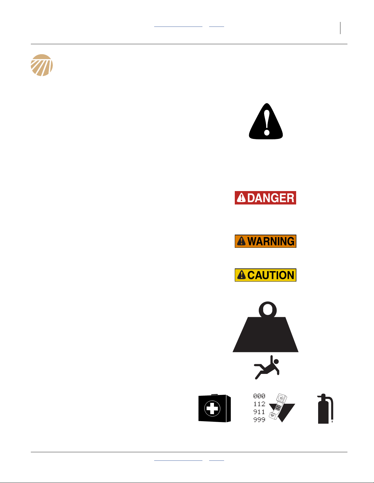
Look for Safety Symbol
The SAFETY ALERT SYMBOL indicates there is a
potential hazard to personal safety involved and extra
safety precaution must be taken. When you see this
symbol, be alert and carefully read the message that
follows it. In addition to design and configuration of
equipment, hazard control and accident prevention are
dependent upon the awareness, concern, prudence and
proper training of personnel involved in the operation,
transport, maintenance and storage of equipment.
Be Aware of Signal Words
Signal words designate a degree or level of hazard
seriousness.
DANGER indicates an imminently hazardous situation
which, if not avoided, will result in death or serious injury.
This signal word is limited to the most extreme situations,
typically for machine components that, for functional
purposes, cannot be guarded.
WARNING indicates a potentially hazardous situation
which, if not avoided, could result in death or serious
injury, and includes hazards that are exposed when
guards are removed. It may also be used to alert against
unsafe practices.
CAUTION indicates a potentially hazardous situation
which, if not avoided, may result in minor or moderate
injury. It may also be used to alert against unsafe
practices.
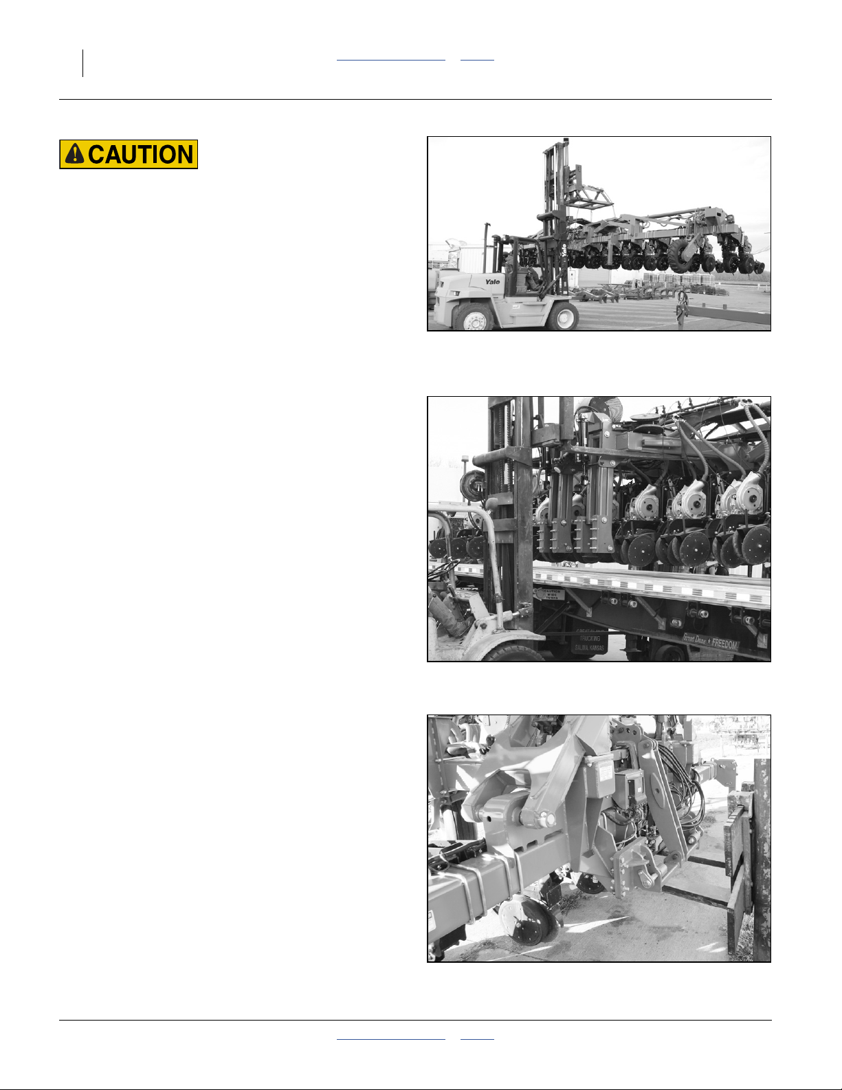
Use Adequate Lifting Means
The main section of this planter is extremely heavy. If
using multiple lifters, make sure each is rated for at least
its share of the load.
Unless using a crane, do not lift and move the planter.
Lift it off the delivery truck, pull the truck away, and lower
the planter to the ground.
> 14,000
POUNDS
Prepare for Emergencies
▲ Be prepared if a fire starts.
▲ Keep a first aid kit and fire extinguisher handy.
▲ Keep emergency numbers for doctor, ambulance, hospital
and fire department near phone.
2012-08-08 Table of Contents Index 401-647Q
Page 6
2 3PYPA Table of Contents Index Great Plains Manufacturing, Inc.
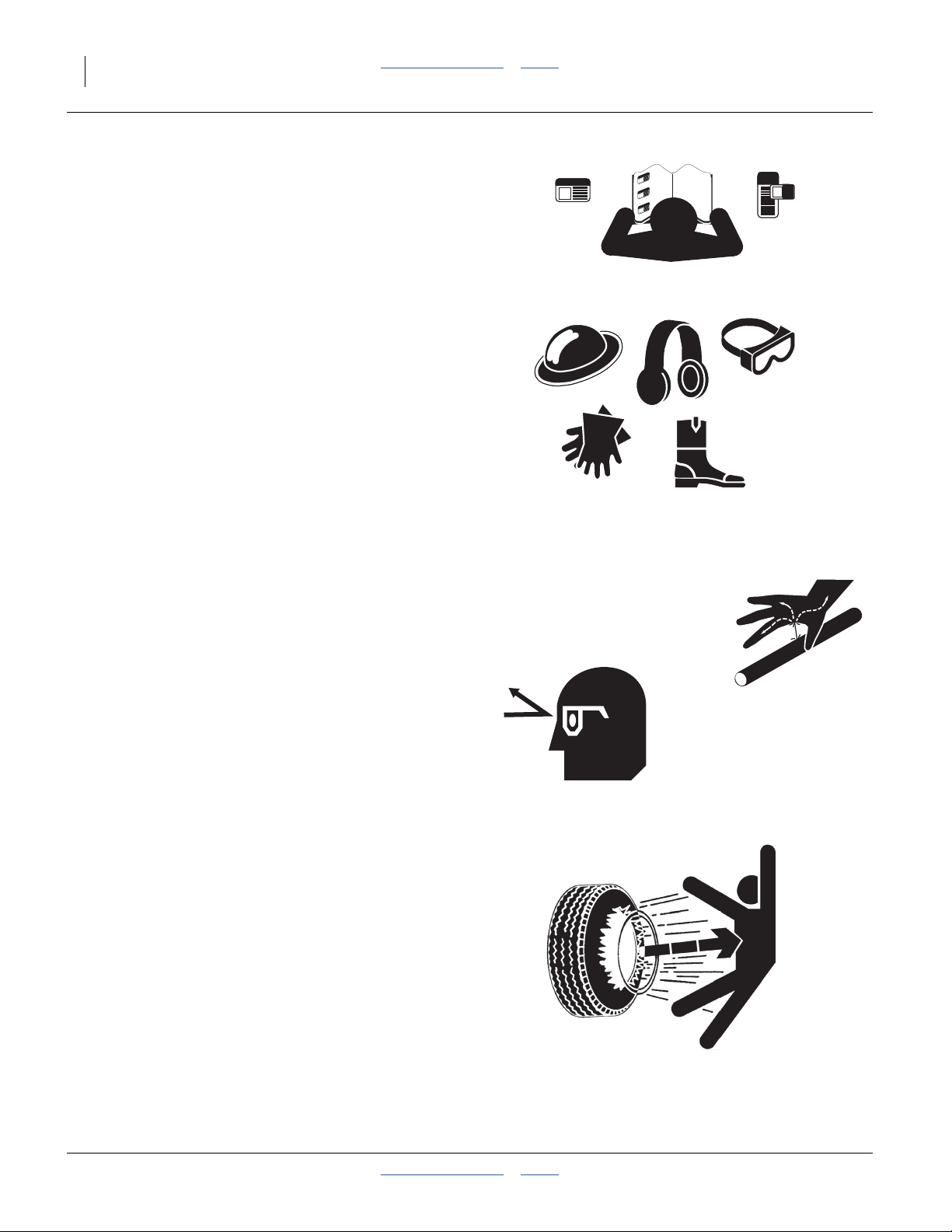
Be Familiar with Safety Decals
▲ Read and understand “Safety Decals” in the Operator
manual.
▲ Read all instructions noted on the decals.
▲ Keep decals clean. Replace damaged, faded and illegible
decals.
Wear Protective Equipment
▲ Wear protective clothing and equipment.
▲ Wear clothing and equipment appropriate for the job. Avoid
loose-fitting clothing.
▲ Because prolonged exposure to loud noise can cause
hearing impairment or hearing loss, wear suitable hearing
protection such as earmuffs or earplugs.
▲ Because operating equipment safely requires your full
attention, avoid wearing entertainment headphones while
assembling or operating machinery.
Avoid High Pressure Fluids
Escaping fluid under pressure can penetrate the skin,
causing serious injury. This planter requires a
Power-Beyond port, which is always under pressure
when the tractor is running.
▲ Avoid the hazard by relieving pressure at other remotes, and
shutting down tractor before connecting, disconnecting or
inspecting hydraulic lines.
▲ Use a piece of paper or cardboard, NOT BODY PARTS, to
check for suspected leaks.
▲ Wear protective gloves and safety glasses or goggles when
working with hydraulic systems.
▲ If an accident occurs, seek immediate medical assistance
from a physician familiar with this type of injury.
Tire Safety
Tire changing can be dangerous and should be
performed by trained personnel using correct tools and
equipment.
▲ When inflating tires, use a clip-on chuck and extension hose
long enough for you to stand to one side–not in front of or
over tire assembly. Use a safety cage if available.
▲ When removing and installing wheels, use wheel-handling
equipment adequate for weight involved.
401-647Q Table of Contents Index 2012-08-08
Page 7
Great Plains Manufacturing, Inc. Table of Contents Index Important Safety Information 3
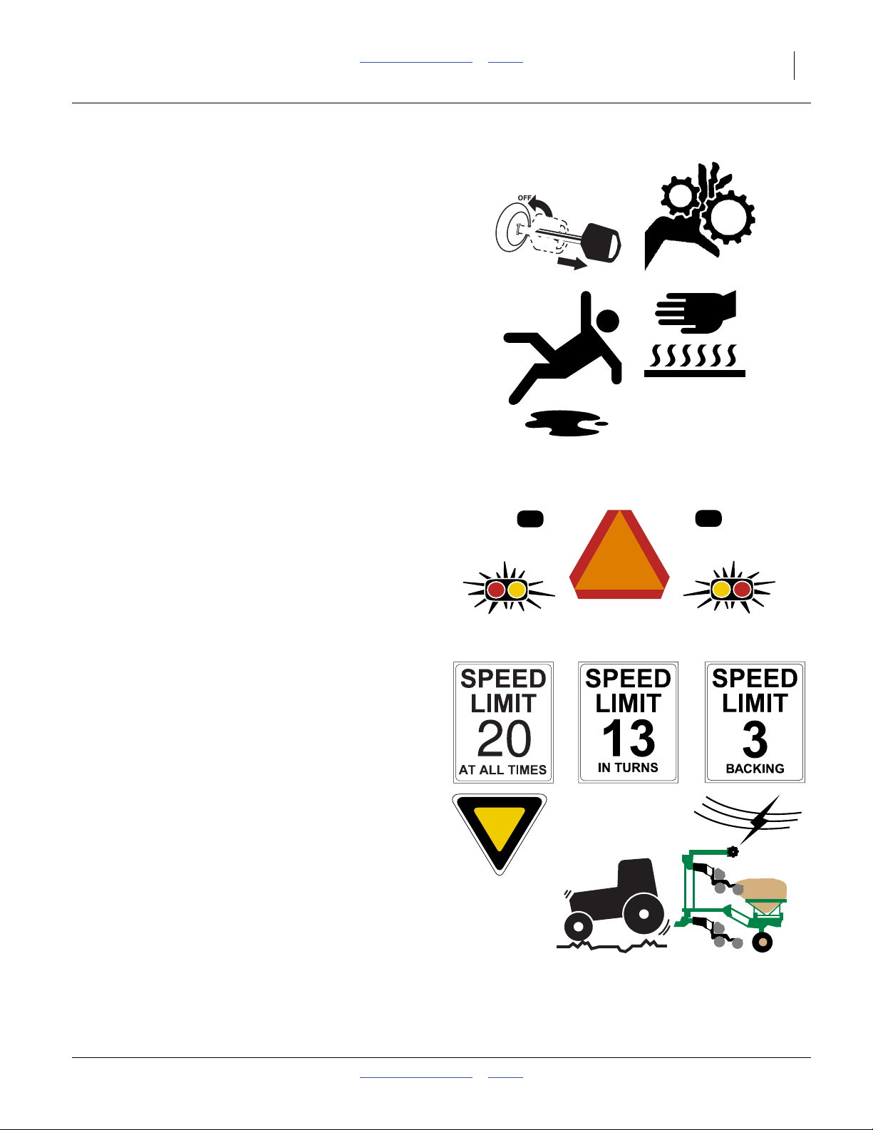
Practice Safe Maintenance
▲ Understand procedure before doing work. Use proper
tools and equipment. Refer to this manual for additional
information.
▲ Work in a clean, dry area.
▲ Lower the planter, put tractor in park, turn off engine, and
remove key before performing maintenance.
▲ Make sure all moving parts have stopped and all system
pressure is relieved.
▲ Allow planter to cool completely.
▲ Disconnect battery ground cable (-) before servicing or
adjusting electrical systems or before welding on planter.
▲ Inspect all parts. Make sure parts are in good condition
and installed properly.
▲ Remove buildup of grease, oil or debris.
▲ Remove all tools and unused parts from planter before
operation.
Use Safety Lights and Devices
Slow-moving tractors and towed implements can create
a hazard when driven on public roads. They are difficult
to see, especially at night.
▲ Use flashing warning lights and turn signals whenever
driving on public roads.
▲ Use lights and devices provided with implement.
Transport Machinery Safely
Maximum transport speed for implement is 20 mph
(32 km/h), 13 mph (22 km/h) in turns. Some rough
terrains require a slower speed. Sudden braking can
cause a towed load to swerve and upset.
▲ Do not exceed 20 mph. Never travel at a speed which does
not allow adequate control of steering and stopping. Reduce
speed if towed load is not equipped with brakes.
▲ Comply with state and local laws.
▲ Do not tow an implement that, when fully loaded, weighs
more than 1.5 times the weight of towing vehicle.
▲ Carry reflectors or flags to mark planter in case of
breakdown on the road.
▲ Keep clear of overhead power lines and other obstructions
when transporting. Refer to transport dimensions in
Appendix, starting on page 64.
▲ Do not fold or unfold the planter while the tractor is
moving.
2012-08-08 Table of Contents Index 401-647Q
Page 8
4 3PYPA Table of Contents Index Great Plains Manufacturing, Inc.
Shutdown and Storage
▲ Lower planter, put tractor in park, turn off engine, and
remove the key.
▲ Secure planter using blocks and supports provided.
▲ Detach and store planter in an area where children
normally do not play.
Safety At All Times
Thoroughly read and understand the instructions in this
manual before operation. Read all instructions noted on
the safety decals.
▲ Be familiar with all planter functions.
▲ Operate machinery from the driver’s seat only.
▲ Do not leave planter unattended with tractor engine
running.
▲ Do not stand between the tractor and planter during
hitching.
▲ Keep hands, feet and clothing away from power-driven
parts.
▲ Wear snug-fitting clothing to avoid entanglement with
moving parts.
▲ Watch out for wires, trees, etc., when folding and raising
planter. Make sure all persons are clear of working area.
401-647Q Table of Contents Index 2012-08-08
Page 9
Great Plains Manufacturing, Inc. Table of Contents Index 5
Introduction
The 3-Point 40-Foot Yield-Pro® Planter (3PYPA) has
been designed with care and built by skilled workers
using quality materials. Proper setup, maintenance, and
safe operating practices will help the customer get years
of satisfactory use from the machine.
Models Covered
3PYPA-1236 12-Row, 36 inch Spacing
3PYPA-1238 12-Row, 38 inch Spacing
3PYPA-1240 12-Row, 40 inch Spacing
3PYPA-1630 16-Row, 30 inch Spacing
3PYPA-24TR36 24-Row (12 Twin), 36 inch Spacing
3PYPA-24TR38 24-Row (12 Twin), 38 inch Spacing
3PYPA-24TR40 24-Row (12 Twin), 40 inch Spacing
3PYPA-3115 31-Row, 15 inch Spacing
3PYPA-32TR30 32-Row (16 Twin), 30 inch Spacing
Description of Unit
The 3PYPA planter is a semi-mounted implement for use
in conventional till, minimum-till, or light no-till conditions.
The 3PYPA accepts optional unit mounted coulters. The
unit mounted coulters make it suitable for light to
moderate no-till conditions only. The 3PYPA includes
25 Series openers with Air-Pro® meters supporting a
wide choice of seed disks. The planter stack-folds for
transport.
Intended Usage
Use the 3PYPA planter to seed production-agriculture
crops only. It is suitable for conventional till, min-till and
moderate no-till conditions. Do not modify the planter for
use with attachments other than Great Plains options
and accessories specified for use with the 3PYPA.
U
R
F
B
L
D
R
L
Figure 1
3PYPA Planter
Compatible Tractors
3PYPA planters include hydraulic steering, which
requires mounting a sensor in the tractor steering gear.
Brackets and instructions are included for the following
tractor brands and models.
Case IH
John Deere
John Deere
John Deere
The tractor must otherwise also meet the requirements
listed under Specifications and Capacities in Appendix A
of the Operator Manual (401-647M).
If the customer does not have one of the brands and
models listed above, contact the factory.
At time of publication, this 3PYPA steering system was
not compatible with articulated tractors.
®
®
®
®
MX or Magnum™ Series
225 through 385
8000 and 8000R Series with
rigid front suspension
8000 Series ILS
(Independent Live Suspension)
8000RT Series tracked
29852
2012-08-08 Table of Contents Index 401-647Q
Page 10
6 3PYPA Table of Contents Index Great Plains Manufacturing, Inc.
Using This Manual
This manual will familiarize you with planning, unloading,
assembly, and some calibration of the planter. Most
operating information is contained in the Operator
manual (401-647M). It is essential that the Operator
manual be available during assembly and checkout.
The information in this manual is current at printing.
Some parts may change to assure top performance.
Definitions
The following terms are used throughout this manual.
A crucial point of information related to the preceding topic.
Read and follow the directions to remain safe, avoid serious
damage to equipment and ensure desired field results.
Note: Useful information related to the preceding topic.
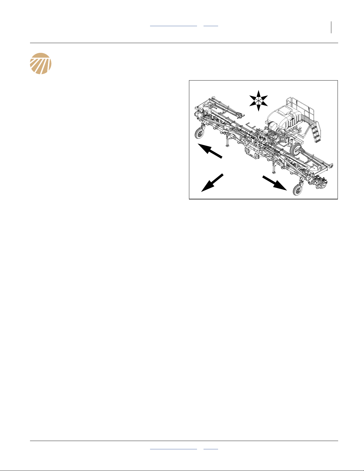
U
R
F
D
Right-hand and left-hand as used in
this manual are determined by facing
the direction the machine will travel
B
while in use unless otherwise stated.
An orientation rose in some line art
L
illustrations shows the directions of:
Up, Back, Left, Down, Front, Right.
Document Family
401-647M Owner’s Manual (this document)
401-647B Seed Rate Charts
401-647P Parts
401-647Q Pre-Delivery manual
DICKEY-john®IntelliAg® manuals:
110011508 Planter/Drill Control, User Level 1
110011501 Planter/Drill Control, User Level 2&3
110011531 3PYPA-1236 Quick-Start Guide
110011531 3PYPA-1238 Quick-Start Guide
110011531 3PYPA-1240 Quick-Start Guide
110011530 3PYPA-1630 Quick-Start Guide
110011528 3PYPA-24TR36 Quick-Start Guide
110011528 3PYPA-24TR38 Quick-Start Guide
110011528 3PYPA-24TR40 Quick-Start Guide
110011529 3PYPA-3115 Quick-Start Guide
110011529 3PYPA-32TR30 Quick-Start Guide
110011126 DICKEY-john® hopper level sensor install
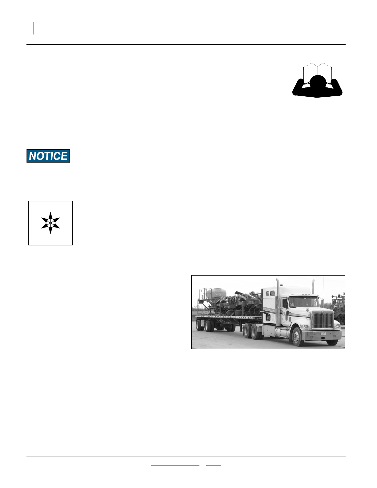
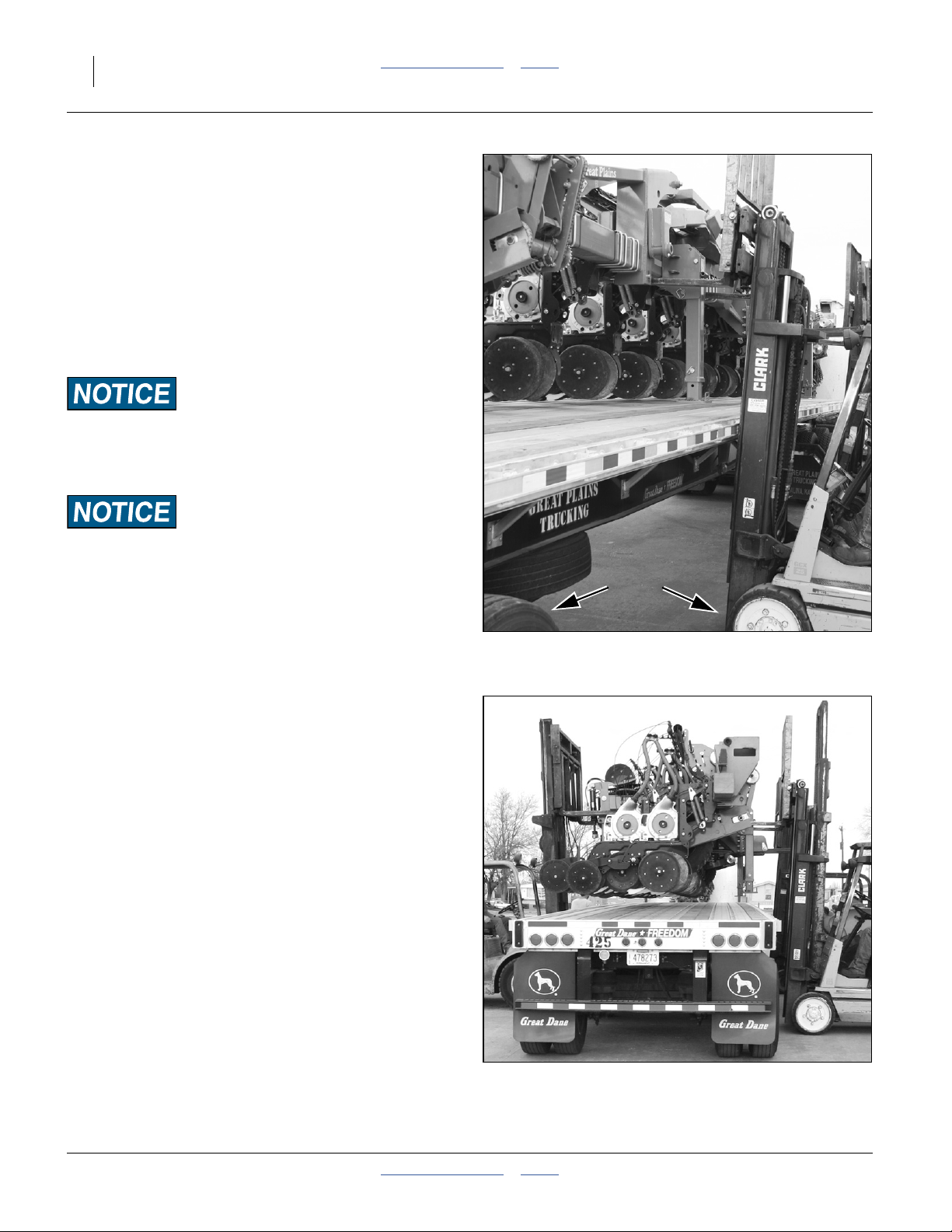
What’s On The Truck
Refer to Figure 2
The 3PYPA planter is delivered from the factory on a
flatbed semi-trailer. It needs to be unloaded from the
truck at the spot where final assembly takes place.
It is expected that final delivery to the customer will be
done using the planter’s own transport wheels, after final
assembly.
Figure 2
Planter Arriving on Truck
25344
401-647Q Table of Contents Index 2012-08-08
Page 11
Great Plains Manufacturing, Inc. Table of Contents Index Introduction 7
Shipment Inventory
The planter is shipped as the following 5 subassemblies
or kits:
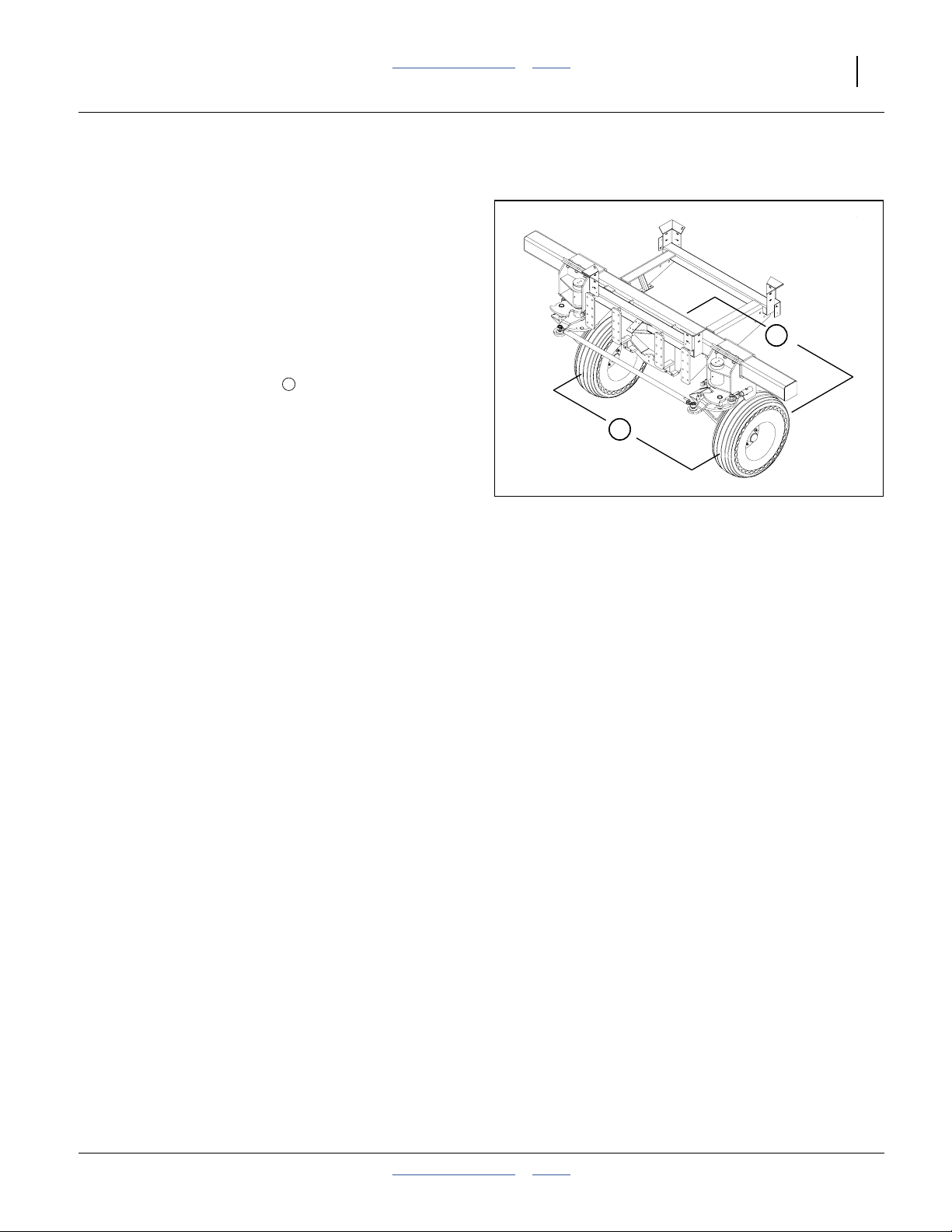
Refer to Figure 3
1. Main frame consisting of:
the complete tool bar with all the row units,
press wheels (two center units strapped on top),
air delivery system,
markers (if ordered),
parallel arms, and
gauge wheels (except on planters with 15 inch row
spacing).
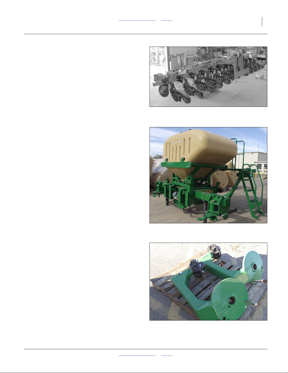
Refer to Figure 4 (which depicts an optional seed hopper on
the seed structure)
2. Rear Seed support structure consisting of
the frame, with
hydraulic steering components,
air distribution box,
caster mounts,
walkboard, and;
82 bushel hopper (if ordered).
Note: The optional hopper is mounted on the frame at
90 degrees from its operating orientation.
Figure 3
Main Frame
29142
Figure 4
31695
Rear Support Structure
Refer to Figure 5
3. Right and left caster assemblies including the
wheel hub and spindle assemblies. See “Caster
Arms” on page 23.
4. Rear lift assist wheels and tires (not shown).
Figure 5
31688
Caster Arms
2012-08-08 Table of Contents Index 401-647Q
Page 12
8 3PYPA Table of Contents Index Great Plains Manufacturing, Inc.
5. A crate containing the hardware to final assemble
the planter, seed monitor console, tractor-side
steering equipment, and seed disks (if ordered).
Assembly and Setup Assistance
To order additional copies of pre-delivery instructions or
operator’s and parts manuals, write to the following
address. Include model numbers in all correspondence.
If you do not understand any part of this manual or have
other assembly or setup questions, assistance is
available. Contact:
Product Support
Great Plains Mfg. Inc., Service Department
PO Box 5060
Salina, KS 67402-5060
Figure 6
Miscellaneous Crate
29938
785-823-3276
401-647Q Table of Contents Index 2012-08-08
Page 13
Great Plains Manufacturing, Inc. Table of Contents Index 9
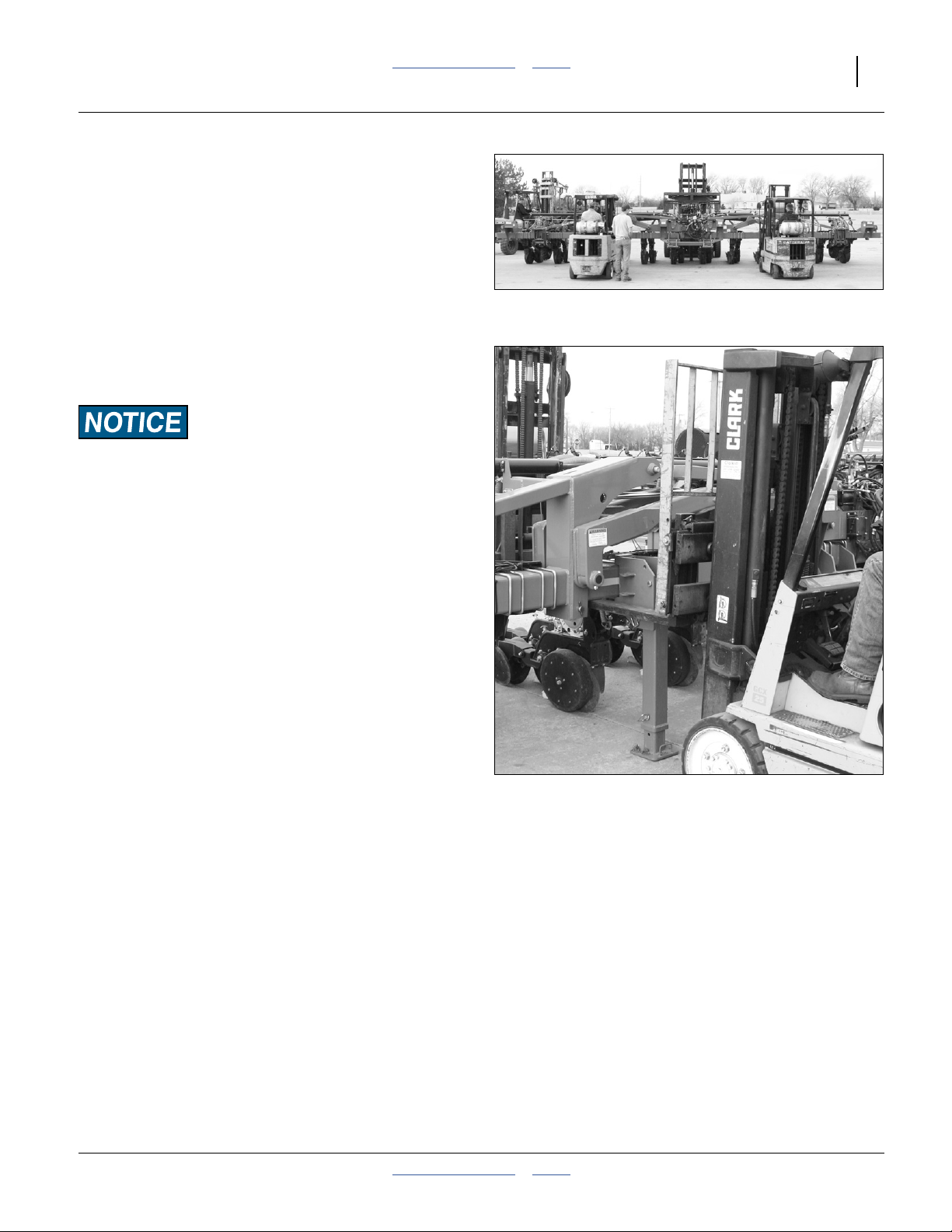
Plan The Mainframe Unload
Unloading the main frame can be a safe, smooth
operation if it is properly planned in advance.
▲ Scope the lift equipment and team size required.
▲ Review the steps with all lift team members.
▲ For multiple lifters, gather lifters and practice simultaneous
lift. Learn control operations for equal lift rates.
▲ Designate an observer to be lift leader.
▲ Have an agreed signalling or command for simultaneous
halting of the lift if any team member detects a problem.
▲ Move the trailer, not the planter.
Use a Hoist or One to Four Lifters
Use lifter(s) with a combined capacity greater than the
weight of the planter main frame.
Do not use more than 4 lifters. There are no safe rear lift
points for more than one lifter.
When using N (2 to 4) lifters, do not assume that each is
getting1⁄Nth of the load. Plan excess capacity. Monitor
load indicators and overload indications or alarms.
> 14,000
POUNDS
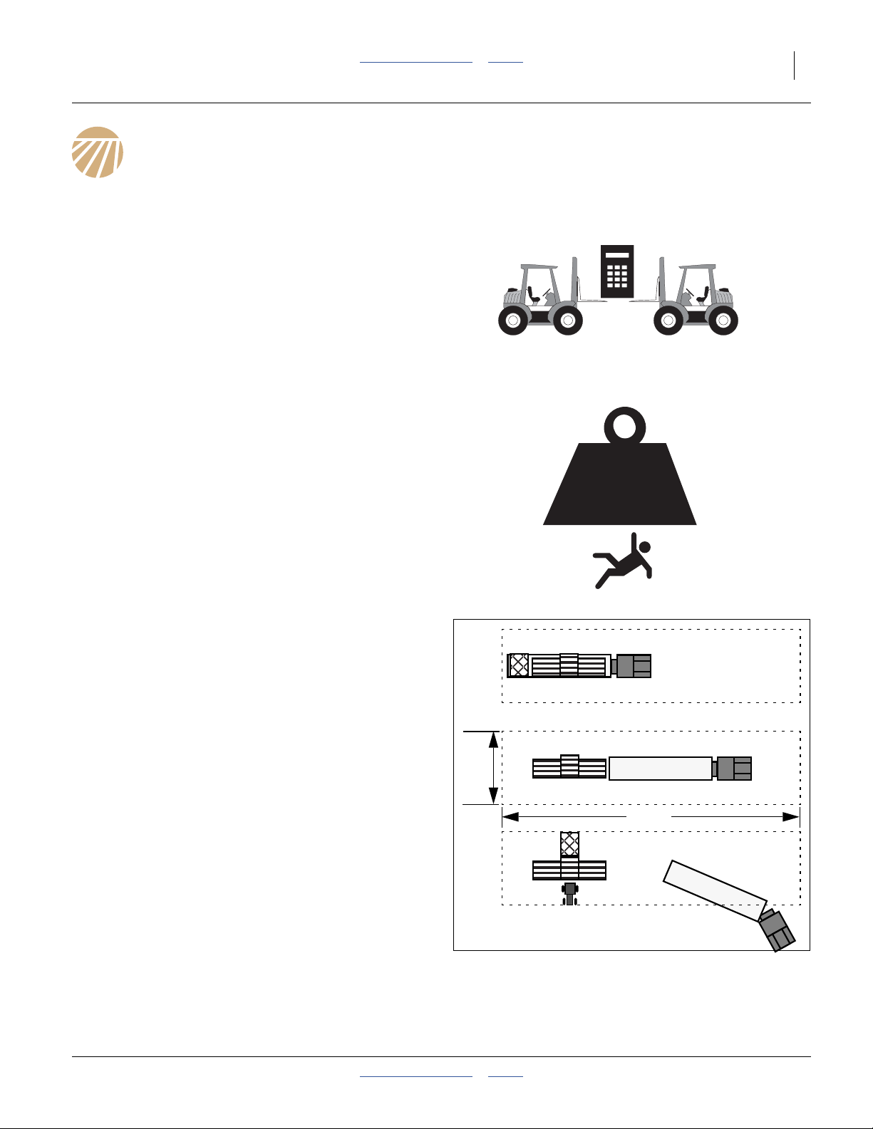
Location Requirements
Until assembled, the planter mainframe is impractical to
move. It needs to be unloaded directly above the spot
where final assembly takes place.
This location needs to be:
• firm level ground or pavement the parking stand loads can approach 100 psi
• there must be adequate space to pull the trailer out
from under the lifted mainframe, without turns,
• there must be adequate open space behind the
mainframe to attach the seed substructure,
• there must be adequate space all around to easily
maneuver fork lifts on both sides, and later behind the
seed frame, and
• there must be adequate space in front of the planter to
attach a tractor and move forward for delivery.
Mark the parking location with traffic cones or pavement
markers.
Note: Unless it is certain that the assembled planter will
only be moved with the tractor on which the
steering sensor is installed, allow ample room in
front of the planter, so that non-sensor tractors
need only make forward moves.
40ft
150ft
Figure 7
Suggested Unload Clearances
2012-08-08 Table of Contents Index 401-647Q
Page 14
10 3PYPA Table of Contents Index Great Plains Manufacturing, Inc.
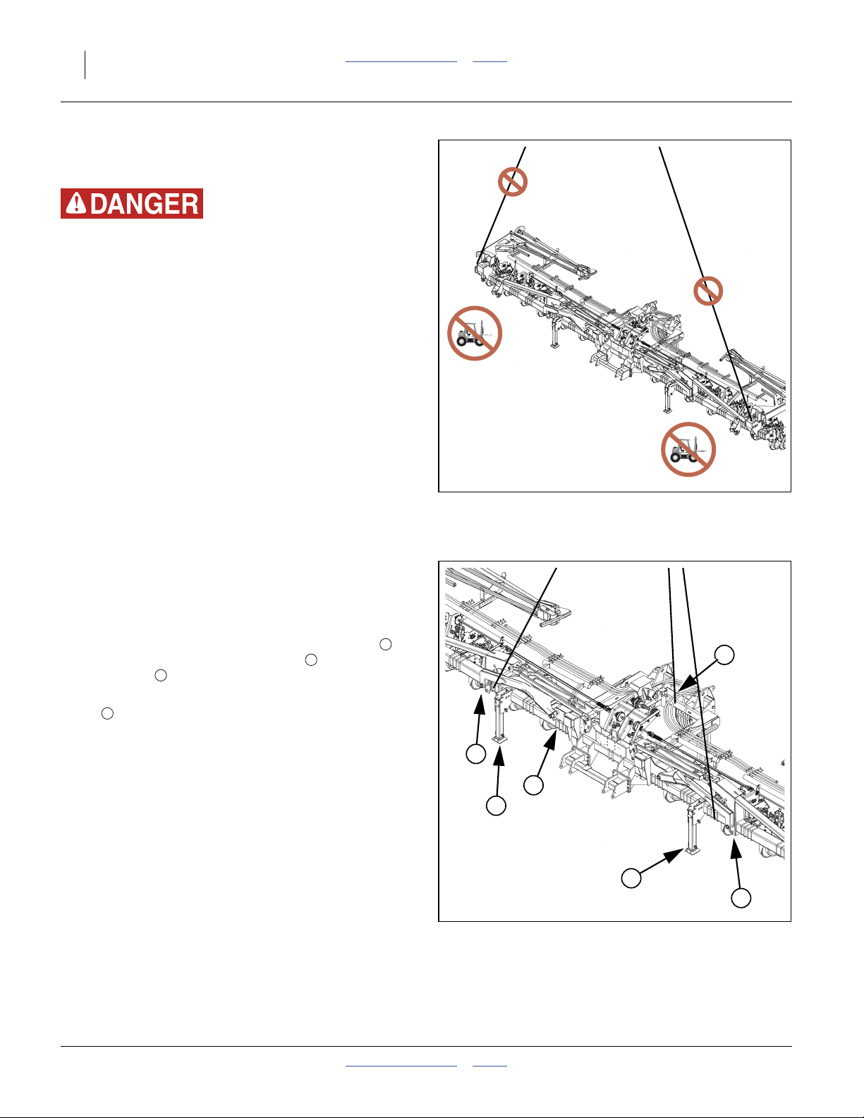
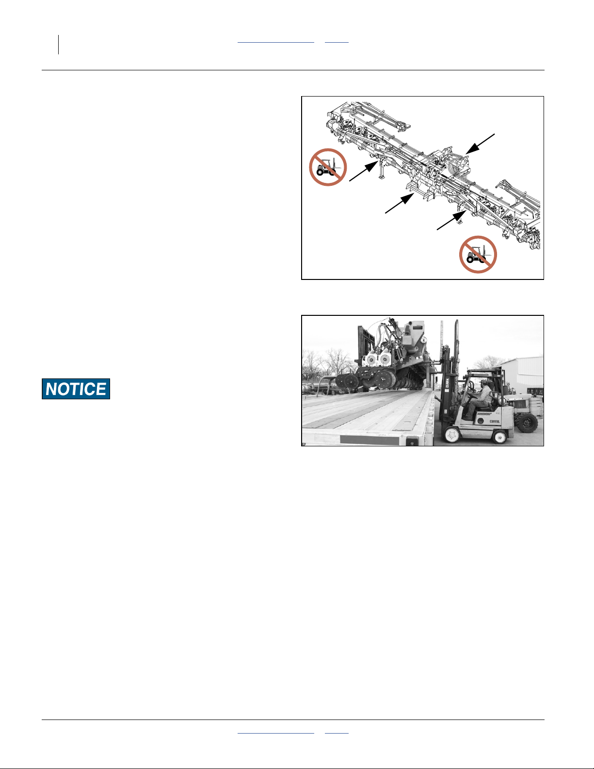
Wings: No Lift - No Hoist
Refer to Figure 8
Lift Failure Hazard:
Do no lifting on the wings beyond the lock-down pins. There is
significant risk of hinge failure and lift collapse, with possible
serious injury or death, and major damage to both planter and
lift equipment.
The folding/stacking wings of the 3PYPA planter must not
be used for lifting. Although they are shipped in the
pinned-down configuration, the hinge/arm system is
designed only to carry the weight of the wings, and not
the center section.
Lift only by the center section.
{
{
Hoist Lifting
Three Hoist Points
Refer to Figure 9
Attach two hoist lines to the center section tool bar ,
outboard of the forward parking stands , but inboard of
the wing joints .
Attach the third hoist line to the center of the rear box
frame and secure that line against side-slip.
4
3
2
1
Figure 8
No-Lift/No-Hoist Regions
25348
4
3
1
2
2
3
Figure 9
3-Hoist Points
401-647Q Table of Contents Index 2012-08-08
25348
Page 15
Great Plains Manufacturing, Inc. Table of Contents Index Plan The Mainframe Unload 11
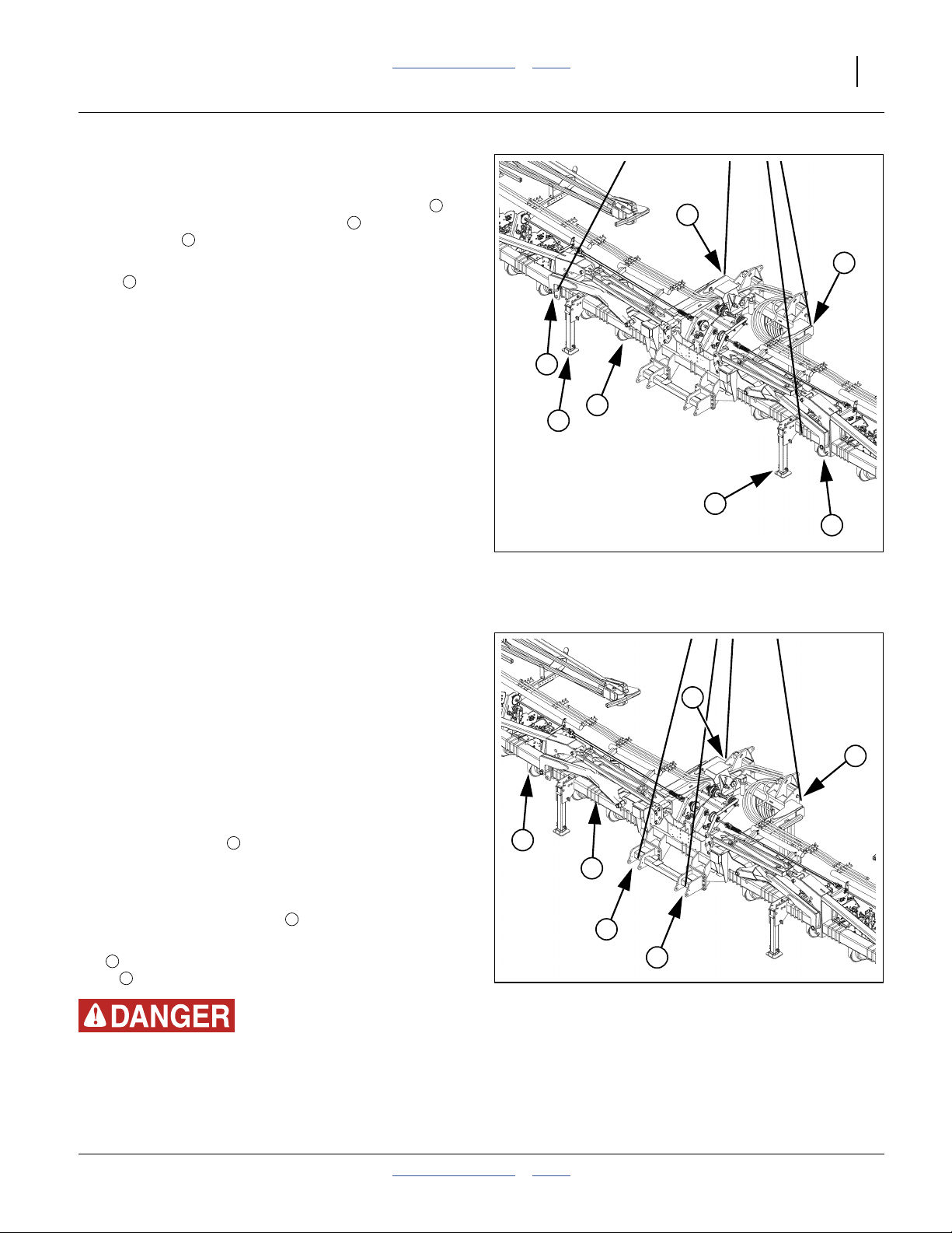
Four Hoist Points
Refer to Figure 10
Attach two hoist lines to the center section tool bar ,
outboard of the forward parking stands , but inboard of
the wing joints .
Attach two hoist lines to the rear corners of the rear box
frame .
8
7
6
5
8
8
7
5
6
6
7
Fork Lifting
Single-Lift Points
Refer to Figure 11 and Figure 12
If a fork lift is available rated for 14,000 pounds or higher,
the planter may be lifted from the front using 4 chains or
straps.
Note: The center of gravity is generally within 12 inches
ahead or behind the row unit springs.
If using 4 hoist lines, attach two lines to the rear corners
of the rear box frame . If using 3 lines, attach one to
the center of the rear tool bar, and secure it so that it
cannot slide side-to-side.
If using 4 lines, you may attach the front lines to the lower
two points of the 3-point hitch .
If using 3 lines, attach the front lines to the front tool
3
bar outboard of the hitch, but inboard of the wing
7
joints .
1
2
Figure 10
4-Hoist Points
25348
1
1
4
3
2
2
Figure 11
Single Lift Hoist Points
25348
Unstable Load Hazard:
Do not attach to the hitch using 3 lines.
2012-08-08 Table of Contents Index 401-647Q
Page 16
12 3PYPA Table of Contents Index Great Plains Manufacturing, Inc.
Tipping Hazard:
Do not attempt single-lift from planter rear. The center of
gravity is too far forward for safety.
Two Lift Points
Refer to Figure 13 and Figure 14
Using two lifters, position the lifter with the lowest
capacity at center frame rear, and lift via center frame
side tubes, as for single-lift.
Position the lifter with the highest capacity at the hitch,
and lift via the cross-tube of the hitch.
Note: The observer/lift leader needs to pay close
attention to planter front-to-back level, and signal
each lift operator how to compensate if imbalance
is detected.
Figure 12
Single Fork Lift
Figure 13
Rear Lift point
25349
25350
Figure 14
25351
Two/Four Front Lift Point
401-647Q Table of Contents Index 2012-08-08
Page 17
Great Plains Manufacturing, Inc. Table of Contents Index Plan The Mainframe Unload 13
Three Lift Points
Refer to Figure 13, Figure 15 and Figure 16
Using three lifters, position one (with the highest
capacity) at center frame rear, and lift via center frame
side tubes, as for single-lift (ref).
Position the other two lifters near, but not beyond, the
center-to-wing connection. Make sure both forks are
inboard, and lifting only the center section.
Unbalanced Load Risk:
Two observers are needed, one for front-back level, and the
other for side-to-side.
The observers need to pay close attention to planter level, and
signal each lift operator how to compensate if imbalance is
detected.
Figure 15
Three-lift points
25352
Figure 16
25353
Front Side Lift Point
2012-08-08 Table of Contents Index 401-647Q
Page 18
14 3PYPA Table of Contents Index Great Plains Manufacturing, Inc.
Four Lift Points
Refer to Figure 13, Figure 15, Figure 16 and Figure 18
Using four lifters, position one (with the highest capacity)
at center frame rear, and lift via center frame side tubes,
as for single-lift.
{
{
Position one lifter at the hitch, and lift via the cross-tube
of the hitch, as for 2-lift.
Position the other two lifters near, but not beyond, the
center-to-wing connection, as for 3-lift. Make sure both
forks are inboard, and lifting only the center section.
Unbalanced Load Risk:
Two observers are needed, one for front-back level, and the
other for side-to-side.
The observers need to pay close attention to planter level, and
signal each lift operator how to compensate if imbalance is
detected.
Figure 17
4-Lift Regions
Figure 18
Four-lift in Progress
25348
25354
401-647Q Table of Contents Index 2012-08-08
Page 19
Great Plains Manufacturing, Inc. Table of Contents Index 15
Unloading
Have the driver spot the truck as marked during
See “Plan The Mainframe Unload” on page 9.
Unload Smaller Items First
Unloading the mainframe is a potentially dangerous
operation.
Reduce risk and complication by first unloading
1. the caster components,
2. the miscellaneous crate and
3. the seed frame
(described below)
Place these components well out of the maneuvering
area needed for unloading the mainframe.
Figure 19
Trailer w/Main & Seed Frames
25355
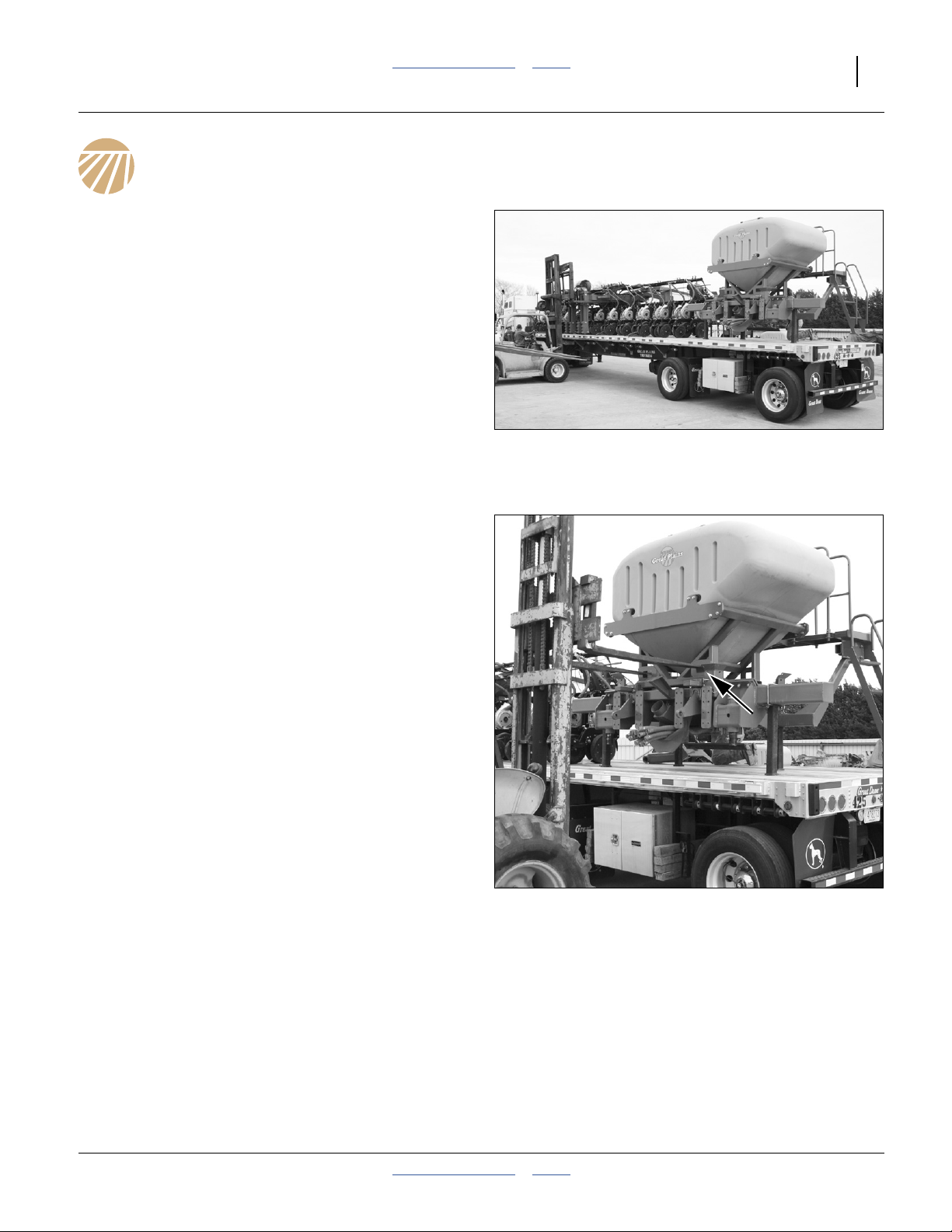
Unload the Seed Frame
Although relatively light compared to the main frame, the
seed frame is tall and an awkward shape for fork-lifting.
It is easiest to approach it from what will later be the
front. If you fork-lift from its back (not recommended),
first swing open and secure the walkboard.
Refer to Figure 20 (which depicts an earlier revision frame)
If the planter was delivered with a hopper, lift via the side
fork lift holes on the diagonal braces.
If the planter did not include a hopper, use chains, and
be sure to check load balance.
4. Remove the seed structure from the trailer.
Figure 20
Approaching Seed frame
25356
2012-08-08 Table of Contents Index 401-647Q
Page 20
16 3PYPA Table of Contents Index Great Plains Manufacturing, Inc.
Unload The Mainframe
Refer to Figure 21 and Figure 22
(which depict a three fork lift)
5. Double-check that all chains and tie-down straps
have been released and stowed.
6. Make sure that all team members are fully briefed
and ready.
7. Set parking brake on trailer tractor.
8. Attach crane hoist lines at planned points or move
fork lifts into planned positions.
Lifter-Trailer Contact Risk:
Do not move lifters or crane so far in that trailer wheels will
not be able to clear them when pulling trailer out from under
planter.
Load “Wedging” Risk:
If using multiple lifters, do not drive the lifts fully forward into
the planter, unless the lifts are known to have precisely vertical
motion. If the load moves forward while lowering, the planter
will tend to push the lifters backward.
Refer to Figure 22 (which depicts a three fork lift)
9. Slowly lift the planter off the trailer bed.
10. Stop lifting about 12in above the bed.
Figure 21
Position Lifters
25357
Figure 22
25358
planter Lifted
401-647Q Table of Contents Index 2012-08-08
Page 21
Great Plains Manufacturing, Inc. Table of Contents Index Unloading 17
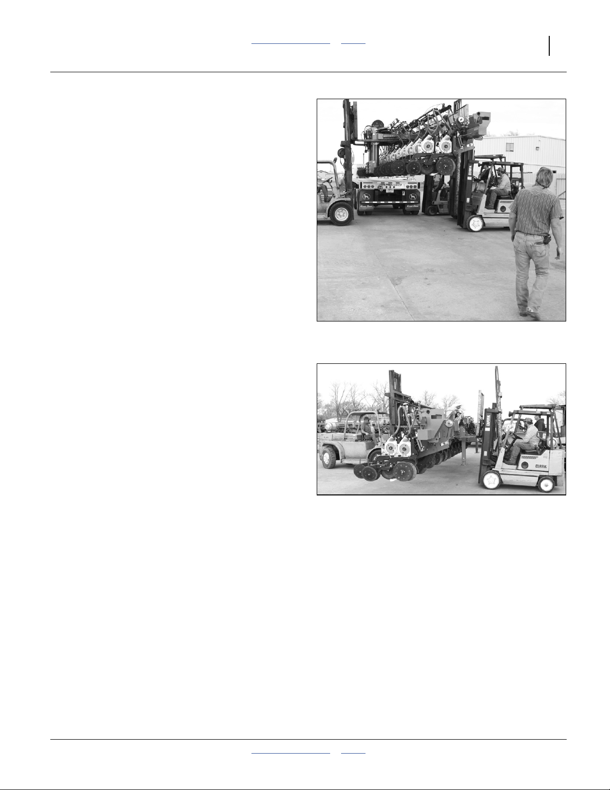
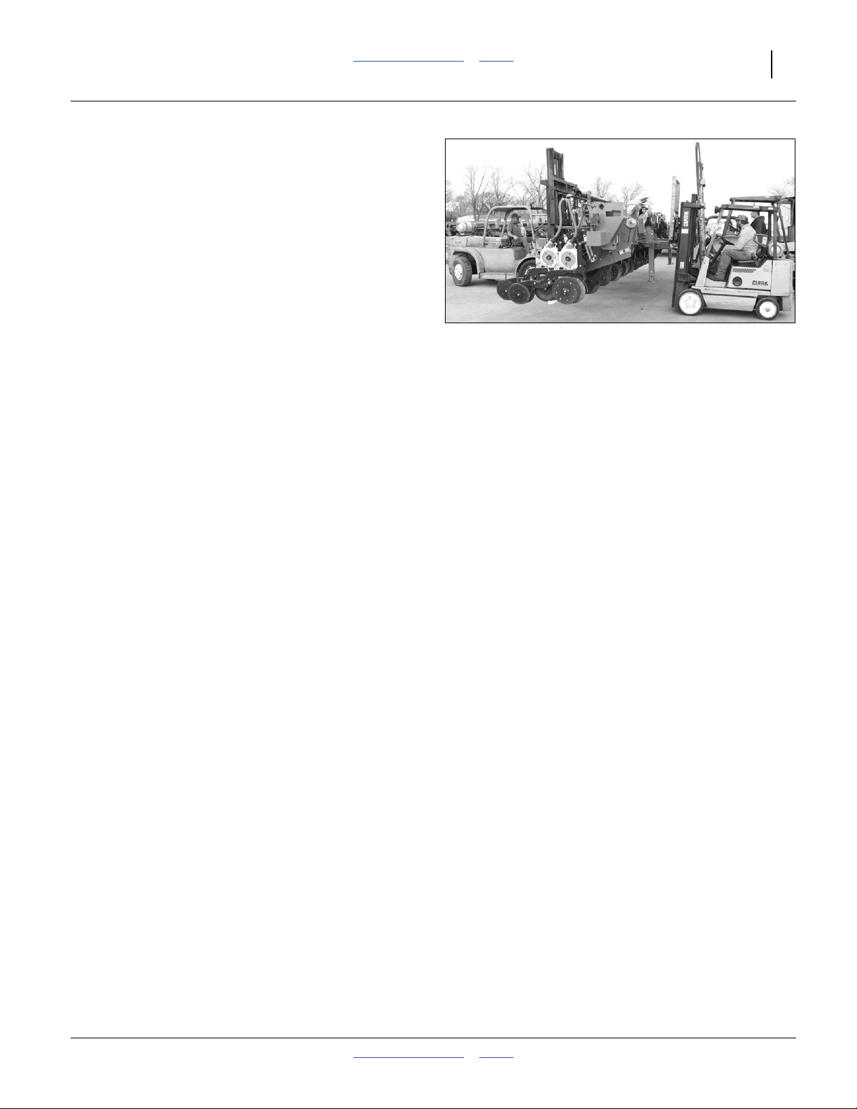
Refer to Figure 23 (which depicts a three fork lift)
11. Have the truck driver slowly pull the trailer straight
out from under the planter.
Refer to Figure 24 (which depicts a three fork lift)
12. Making sure to keep level from front to back and
side to side, slowly lower the planter.
13. If the planter has the gauge wheels swung back
under for shipment, stop lowering about 18 inches
above the ground.
If the planter does not have the gauge wheels
mounted, skip to step 20.
Figure 23
Truck Pulling Away
Figure 24
Planter Lowering
25359
25360
2012-08-08 Table of Contents Index 401-647Q
Page 22
18 3PYPA Table of Contents Index Great Plains Manufacturing, Inc.
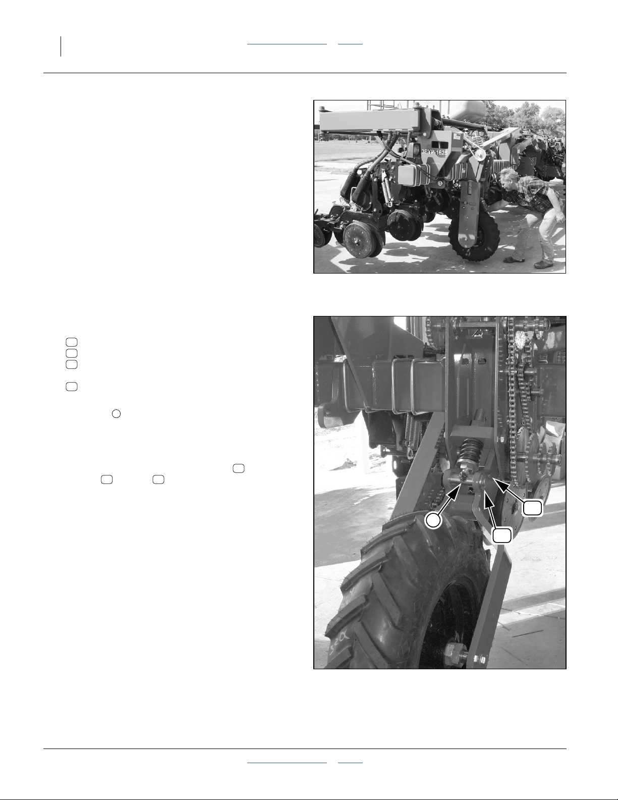
Refer to Figure 25
14. Swing the gauge wheels most of the way out in front
of the planter.
Refer to Figure 26
15. Remove and save one set (not all shown):
43
803-006C NUT HEX 1/4-20 PLT
52
804-006C WASHER LOCK SPRING 1/4 PLT
87
802-167C HHCS 1/4-20X1 1/2 GR5
and remove the pin:
24
402-209H PIN 1 X 4 5/8 NONROTATE
16. Orient the cross-tube of the adjustment rod
weldment so that the grease zerk is facing
1
forward.
17. Continue swinging wheel forward until cross-tube
aligns with pin hole.
18. Re-insert pin. Secure with saved bolt ,
washer and nut .
52 43
87
19. Repeat this for the other gauge wheel assembly.
Figure 25
Swing Gauge Wheels Forward
1
24
25361
87
Figure 26
29186
Secure Gauge Wheel with Pin
401-647Q Table of Contents Index 2012-08-08
Page 23
Great Plains Manufacturing, Inc. Table of Contents Index Unloading 19
Refer to Figure 27
20. Making sure to keep level from front to back and
side to side, slowly complete lowering the planter to
the ground.
21. Uncouple hoist lines, or lower forks and withdraw
lifters.
Figure 27
Planter Lowered to Ground
25360
2012-08-08 Table of Contents Index 401-647Q
Page 24
20 3PYPA Table of Contents Index Great Plains Manufacturing, Inc.
Planter Assembly
Press Wheel Shipping
Refer to Figure 28
Depending on machine configuration, two or more press
wheel assemblies may have been shipped
dismounted. If only two were dismounted, they will have
been shipped bolted to the rear corners of the main
frame . If none or all were dismounted, skip to step 24.
22. Remove the bolt, nut, and any washers that
23. Set the press wheel assemblies aside. They are
2
secure the press wheel assemblies to the main
frame. These fasteners are not reused.
installed at step 102. Leaving them off now eases
access to this part of the planter.
1
3
3
2
1
Figure 28
Press Wheel Shipping
25365
Shipping Stands
As delivered from the factory, the planter includes:
• 2 parking stands intended to remain on the planter
(front tool bar just inboard of wing joints)
Refer to Figure 29 (which depicts an earlier 3PYP parallel
arm configuration - the shipping stand has not changed)
• 1 main frame shipping stand that is removed after
assembly, but needs to remain with the customer, as it
eases changing caster tires
• 4 seed frame shipping stands that are not needed
after final assembly.
• Do not remove any of these stands until instructed.
During assembly, let the planter main frame rest on the
two parking stands on front of the tool bar and the
shipping stand under the rear tube of the frame. Do not
let any of the supports sink into the ground.
1
1
Figure 29
Main Frame Shipping Stand
29209
401-647Q Table of Contents Index 2012-08-08
Page 25
Great Plains Manufacturing, Inc. Table of Contents Index Planter Assembly 21
Prepare Parallel Arms
The seed frame is attached to the main frame’s parallel
arms, after releasing the arms from their shipping
configuration.
Refer to Figure 30
24. Remove and save the 32 sets of:
47
803-021C NUT HEX 5/8-11 PLT
58
804-022C WASHER LOCK SPRING 5/8 PLT
36
802-057C HHCS 5/8-11X2 1/4 GR5
25. Remove and save the extra pin and cotter pin
stored near the spare shear bolts.
Refer to Figure 32
The parallel arms are shipped mounted to the rear of the
main frame and each is held in the vertical down position
by a 11⁄4inch diameter pin .
26. Remove both arm locking pins . These pins are
not re-used.
27. Remove and save the cotter pins, washers and
cross-pins in the free ends of the lift-assist
cylinder clevises.
5
4
4
3
36
3
47
58
Figure 30
Parallel Arm Flange Bolts
4
29147
Refer to Figure 32 (which depicts elevating with a strap and
forklift, and depicts the clevis attached [step 31])
28. Using a hoist, elevate each parallel arm until
roughly horizontal. Parallel arms can be supported
by re-inserting pins from step 27.
4
5
Figure 31
Parallel Arm Shipping Pin
4
Figure 32
Elevate and Support Parallel Arm
29145
29146
2012-08-08 Table of Contents Index 401-647Q
Page 26
22 3PYPA Table of Contents Index Great Plains Manufacturing, Inc.
Refer to Figure 33
29. Insert the pin saved at step 25 into the lower lug
6
hole .
6
Refer to Figure 34
30. Use the hoist to adjust the height of the parallel
arms until the lift-assist cylinder rod clevis can be
aligned with forward hole of the lug.
31. Secure with pin & hardware removed and saved at
step 27.
32. Carefully lower the hoist. The lift-assist cylinders
may or may not fully extend, depending on how
much air is in the hoses and cylinders.
Mount Seed Box Frame
Refer to Figure 35
Note: If no hopper is included, leave walkboard closed,
and lift structure using 3 adequately sized chains
so it lifts evenly side-to-side and front-to-back.
33. Open the walkboard by removing the pin ,
swinging it open to the right. Secure with keeper.
34. Lift the seed support structure from the rear using
the fork holes in the hopper support.
5
Refer to Figure 36
Have the Grade 5 bolts , washers and nuts
47 58 36
saved in step 24 at hand.
35. Position the flanges on the front of the structure
6
to mate up with the corresponding flanges on the
rear of one of the two parallel arms. Secure with 16
bolts, washers and nuts.
36. Use the lift or hoist to align the flanges on the other
side. Secure with 16 bolts, washers and nuts.
4
Figure 33
29148
Lower Lug Pin
Figure 34
29149
Pin Lift-Assist Cylinder
4
5
Figure 35
Seed Box Frame w/Hopper
25368
401-647Q Table of Contents Index 2012-08-08
Page 27
Great Plains Manufacturing, Inc. Table of Contents Index Planter Assembly 23
Seed Cart Self-Lift
If only one hoist or fork lift is available (the one presently
supporting the seed cart structure), it will be needed for
hoisting casters. The lift-assist cylinders are capable of
supporting the entire weight of the seed structure if the
mainframe is hitched to a 3-point tractor, and the lift
hoses (blue) are connected to a tractor remote.
If you need to free the hoist/lift:
37. Lower the seed structure onto its shipping stands.
38. Hitch a 3-point tractor and connect the lift-assist
circuit.
39. Raise the seed structure until the parallel arms are
slightly above level at the rear.
40. Put blocks or jack stands under the rear shipping
strands of the seed structure.
47 58 36
Align Seed Box with Arms
6
Figure 36
7
7
29151
Remove Cart Shipping Stands
41. Remove the four shipping stands from the seed
structure. These are not re-used.
7
Install Casters
Determine how to lift move and align the caster arms
with the available lifting equipment.
Note: Recommend securing caster arm by clamping to
fork of lift.
Caster Arms
Refer to Figure 37
42. The left and right caster arms are identical.
Figure 37
LH/RH Caster Arms are Identical
31678
2012-08-08 Table of Contents Index 401-647Q
Page 28

24 3PYPA Table of Contents Index Great Plains Manufacturing, Inc.
Install Left and Right Caster Arms
Refer to Figure 38 and Figure 39
43. Carefully secure one caster arm to a lift or hoist
capable of holding the arm with the pivot hole
vertical, and remaining clear of the seed structure
while positioning the arm.
44. At the cart, remove and save one set of:
48
803-026C NUT LOCK 3/4-10 PLT (not shown)
40
802-360C HHCS 3/4-10X6 1/2 GR5
61
804-102C PIVOT THRUST WASHER
Coat the spindle with anti-seize compound.
45. Align the arm under the spindle. Place the thrust
washer on the spindle before the spindle
contacts the arm.
46. Fully raise the arm on the spindle. If the spindle
rises, tap it down with a rubber mallet.
47. Align the holes in the arm and the spindle, and
secure the arm to the spindle with the cross-bolt
and nut .
48. Repeat steps to install other caster arm.
61
48
40
Figure 38
Move Caster Arm to Spindle
31693
Install Caster Wheels
Refer to Figure 40 (tie rods not installed)
49. Remove and save the lug nuts (not shown)
51
803-219C NUT LUG 5/8-18 X 90 DEG PLT
from the right caster hub.
50. Roll one of the wheel assemblies (they are identical)
up to the caster arm. Orient the side with the valve
stem away from the hub (toward seed structure
center).
51. Adjust the elevation of the seed structure so that the
wheel just fits over the threaded studs on the hub.
This eases the assembly.
52. Seat the wheel on the hub and secure with saved
lug nuts .
53. Rotate caster until the 11⁄4inch diameter alignment
pin holes in the caster top plate and the steering
arm align. Install the alignment from the bottom and
lock in place with1⁄2inch bolt and nut supplied.
51
40
Figure 39
Cross Bolt and Thrust Washer
Figure 40
Install Caster Wheels
61
31694
31691
401-647Q Table of Contents Index 2012-08-08
Page 29
Great Plains Manufacturing, Inc. Table of Contents Index Planter Assembly 25
Adjust Steering Tie Rod
Refer to Figure 41
54. Adjust tie rod to these objectives:
• The rod is installed at the factory but tire
alignment needs to be checked and adjusted
once final field assembly is complete.
• Pivot both casters until the tires are close to full
trailing (straight running) orientation. All
measurements must be made with the tires in a
position to have the planter traveling straight
forward.
• Measure the distance from the center of one
D
tire to the center of the other tire both in front of
the tires as well as behind the tires.
• The measurements are to be equal. If the
measurement across the front of the tires is less
than the measurement across the back of the
tires then the tie rod needs to be lengthened. If
the measurement across the front is more than
the measurement across the back then the tie rod
needs to be shortened.
• Make the appropriate adjustment then re-center
the tires and take another set of dimensions.
• Repeat as necessary until the dimensions are
equal.
• Do NOT have any toe in or toe out.
• Tighten the lock nuts on the ends of the tie rod.
(Right side has right-hand thread and left side
has left-hand thread.)
D
Figure 41
Tie Rod Adjustment
D
31679
2012-08-08 Table of Contents Index 401-647Q
Page 30
26 3PYPA Table of Contents Index Great Plains Manufacturing, Inc.
Lower Seed Box Structure
55. Check tire pressure. See “Tire Inflation Chart” on
page 65.
56. Depending on how the structure is being supported,
use the lift-assist cylinders, hoist or lift to lower the
seed box structure onto the tires.
Remove Hopper (Option)
If no seed hopper was included, skip to step 60.
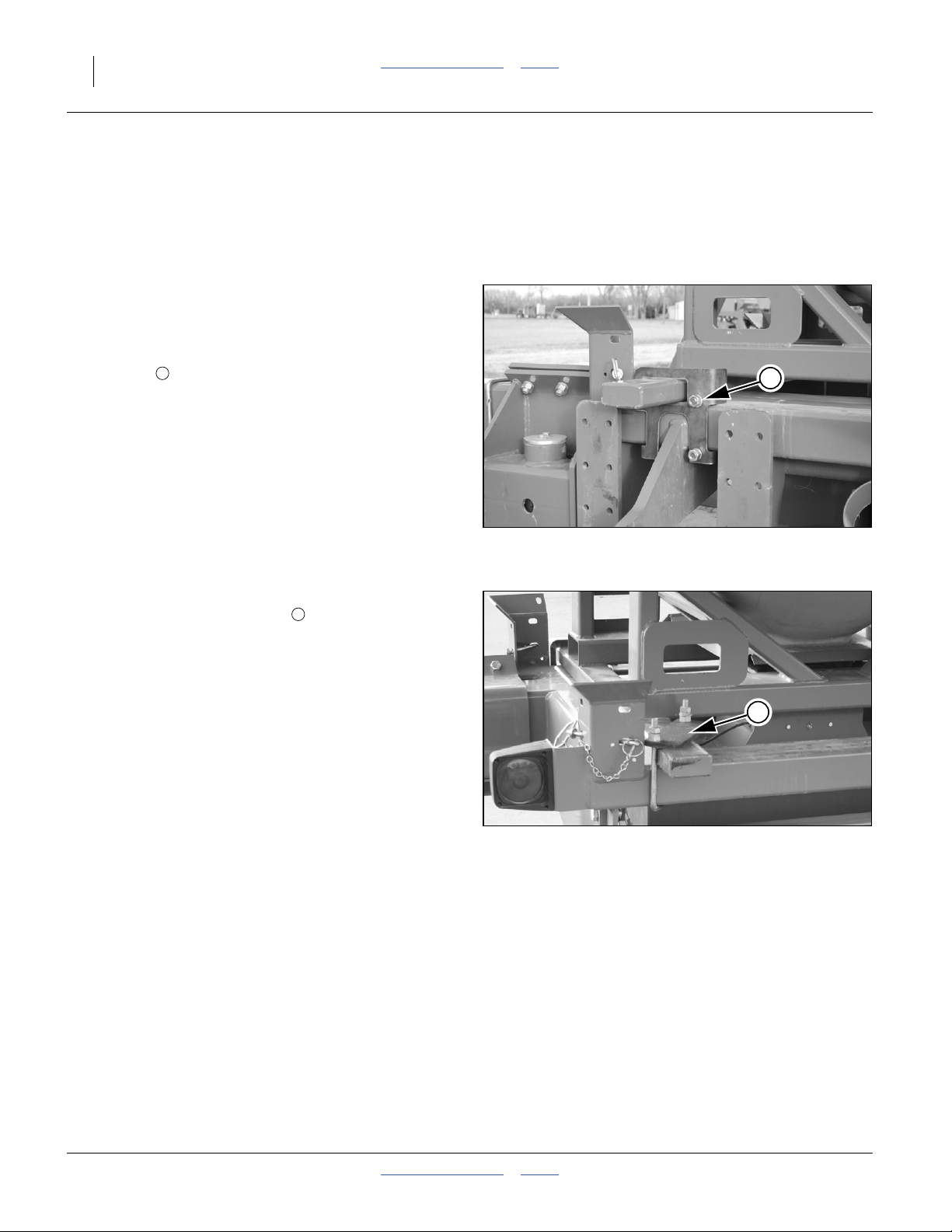
Refer to Figure 42
57. Remove the bolts holding the hopper shipping
bracket . The bracket and bolts are not reused.
1
1
Refer to Figure 43
58. Remove the U-bolt and bar restraining the
hopper on the opposite side. The bar and fasteners
are not reused.
59. Use a fork lift to remove the hopper and set it out of
the way temporarily.
Note: For shipping, the hopper was installed sideways on
the seed support structure. It must be removed and
correctly remounted before use. Remount is done
at step 110.
2
Figure 42
Hopper Shipping Bracket
Figure 43
Hopper Shipping U-Bolt
25369
2
25370
401-647Q Table of Contents Index 2012-08-08
Page 31
Great Plains Manufacturing, Inc. Table of Contents Index Planter Assembly 27
Connect Steering Hoses
Note: Hose and harness installation consumes cable ties
provided in the parts crate. Use the shortest tie
length at each point.
ST2
ST2
ST1
ST1
60. Locate the two steering hoses coiled up at the rear
left end of the center frame. Cut the tie holding the
coil.
Refer to Figure 44 and Figure 45
61. Route the hoses:
under the upper cross tube at the mainframe
parallel arm pivot weldment,
over the upper forward arm pivot tube,
along the inside of the lower left parallel arm,
over the lower rear arm pivot tube,
beneath the steering tie rods,
down to the rod end of the left steering cylinder.
62. To help in the connecting of the steering hoses, the
two hoses have different size connector fittings.
Connect each hose to its mating fitting attached to
the seed carrier structure just to the inside of the left
parallel arm bracket (see photo).
63. Check that all steering hose and fitting connections
are tight.
64. Secure the hoses with ties.
Route Steering Sensor Lead
Refer to Figure 46
65. Identify the seed cart steering sensor lead . It is a
4-pin circular connector that is part of the harness
Find:
315-032 HARNESS IMPLEMENT F/FWD STEER
14
Route this lead along the ST1 and ST2 hoses.
66. Connect the steering sensor lead to the left end
of the left steering cylinder
14
1
14
14
Figure 44
Identify Steering Hoses
Figure 45
Steering Hose Routing
1
31680
31696
Figure 46
Steering Sensor Routing
2012-08-08 Table of Contents Index 401-647Q
31697
Page 32

28 3PYPA Table of Contents Index Great Plains Manufacturing, Inc.
Route Lighting/Seed Box Leads
Refer to Figure 47
67. Uncoil the lighting and seed box sensor harnesses.
Route them along the steering hoses, and under the
main cart cross tube.
Note: There are two cable clamps attached to the
inside of the cart side frames, near the main cross
tube, shown as gray “J” shapes in Figure 47.
68. Using a cable tie, loosely secure the harness bundle
to the left cable clamp.
69. Identify the Right light harness . Route it along the
back side of the main cross tube, to the right side
cable clamp . Using a cable tie, loosely secure the
C
harness at that side.
Refer to Figure 48
70. At each tail light assembly, route the lead through
the nearby hole in the cart side frame.
H
71. Route the Right light harness along the inside of
the right side frame and connect it to the right tail
light lead.
72. Route the Left light harness along the inside of
the left side frame and connect it to the left tail light
lead.
73. Route the seed box sensor harness along the left
light harness, and then to the seed box sensor lead.
Use a cable tie to secure the sensor harness to the
light harness. Plug sensor harness and cable
together.
74. Check that steering hoses, and all cables have
adequate slack for parallel arm movement (at both
ends or arms). Tighten the other cable ties.
C
R
R
L
S
S
R
C
Figure 47
Lighting and Seed Box Harnesses
H
Figure 48
Tail Light Lead
L
C
25371
29169
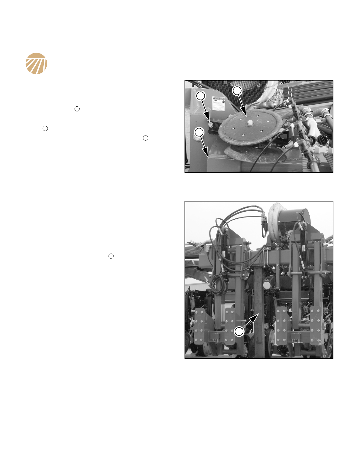
Adjust Air Box Pads
Refer to Figure 49
If the planter was delivered without a hopper, verify pad
positions.
If the planter was ordered with a seed hopper, two corner
1
pads will have been lowered to allow transport
mounting of the hopper.
75. Loosen two bolts on each corner pad bracket.
2
76. Raise the pads until their top surfaces are 1 inch
higher than the perimeter pad .
3
77. Tighten the bolts.
401-647Q Table of Contents Index 2012-08-08
1
3
2
Figure 49
Air Box Pads
25371
Page 33

Great Plains Manufacturing, Inc. Table of Contents Index Planter Assembly 29
Connect Seed Hose Rack
Refer to Figure 51
For shipping, the seed tube hoses and rack ( or )
that interconnect the air box and mainframe are strapped
to the walkboard. The seed tubes/rack need to be
dismounted and connected between the air box manifold
and the inner ends of the wing tubes.
Refer to Figure 50
78. Dismount the rack assembly from walkboard. It may
have a tag with the part number of the tube rack:
401-367K SEED TUBE RACK ASSY REAR 16
15
401-368K SEED TUBE RACK ASSY REAR 12
16
79. Identify rack orientation:
Ends: The hose lengths and mounting hardware are
different for each end of the rack. The end with the
longer hoses connects to the wing tubes. The end
with the shorter hoses connects to the air box. The
air box end also has pivot holes in the frame.
1
15 16
Wings
2
1
15
16
Figure 50
Seed Tube Rack, Dismounted
Air Box
29944
Bottom: At the front (wing) end of the rack, the
bottom side frame has a short rail on each side.
Refer to Figure 51
80. Note the idler spools on each side of the inner
rear portion of the parallel arm brackets. The
forward end of the rack rests on these and is free to
slide during vertical movement of planter
components.
Refer to Figure 52
The rear ends of the outside tubes of the seed tube rack
have large holes to accept a pivot sleeve for mounting.
1
3
2
2
3
Figure 51
Seed Tube Rack, Below Forward
1
Figure 52
Rear Rack Pivot Hole
2
3
29170
25379
2012-08-08 Table of Contents Index 401-647Q
Page 34

30 3PYPA Table of Contents Index Great Plains Manufacturing, Inc.
Refer to Figure 53 and Figure 54
The hardware for this mount is normally pre-installed on
the rear parallel arm flange weldments, but may be in the
miscellaneous crate.
81. Select or remove two sets of:
46
803-020C NUT HEX 1/2-13 PLT
56
804-015C WASHER LOCK SPRING 1/2 PLT
11
120-306D TUBE RND 1 OD X 7/32W X 2.13
58
802-042C HHCS 1/2-13X3 3/4 GR5
and two (four total):
62
804-113C WASHER FLAT 1/2 USS HARD PLT
Place the lock washer on the bolt.
82. Place a flat washer , than a spacer tube , on
each bolt .
83. From the inside of the rack, pass each bolt
assembly through the hole at the lower/rear pivot
end of the rack. Add another flat washer .
84. Align the rack holes with the weldment holes .
Pass the bolt thread through the weldment holes.
Secure each bolt with a lock washer and nut .
The next activities (connecting seed hoses to the air box
manifold and wing tubes) require the port mapping tables
on the following two pages. Installation steps resume on
page 33.
58
62 11
1
62
1 3
56 46
58
3
56
46
Rack Pivot Hardware
62
Figure 53
1
11
62
29839
58
Figure 54
Rack Pivot Installed
58
29173
401-647Q Table of Contents Index 2012-08-08
Page 35

Great Plains Manufacturing, Inc. Table of Contents Index Planter Assembly 31
Seed Hose Routing
Port Identification: “12 Port”
Air Box Ports (P) Splitter
LR
L
P01
P06
P11
“12 Port” Seed Hose Connection Stations (Facing Forward)
R
P16
Figure 55
T07 T12
T01 T06
Hose Rack Tubes (T)
Y
()
No
Splitter
(|)
29174
Port Assignments: 12, 23 and 24-Row
3PYP-1236: 12-Row, 36in 3PYP-1238: 12-Row, 38in 3PYP-1240: 12-Row, 40in
Left Wing Center Section Right Wing
Box Port P04 P05 P06 P01 P02 P03 P16 P15 P14 P13 P12 P11
Rack Tube T07 T08 T09 T01 T02 T03 T06 T05 T04 T12 T11 T10
Splitter
Row Unit R01 R02 R03 R04 R05 R06 R07 R08 R09 R10 R11 R12
|||||||||||
|
3PYP-2320: 23-Row 20in
Left Wing Center Section Right Wing
Box Port P04 P05 P06 P01 P02 P03 P16 P15 P14 P13 P12 P11
Rack Tube T07 T08 T09 T01 T02 T03 T06 T05 T04 T12 T11 T10
Splitter
Row Unit 01 02 03 04 05 06 07 08 09 10 11 12 13 14 15 16 17 18 19 20 21 22 23
3PYP-24TR36: 24-Row (12 Twin), 36in 3PYP-24TR38: 24-Row (12 Twin), 38in 3PYP-24TR40: 24-Row (12 Twin), 40in
YYYYYY
|
YYYYY
Left Wing Center Section Right Wing
Box Port P04 P05 P06 P01 P02 P03 P16 P15 P14 P13 P12 P11
Rack Tube T07 T08 T09 T01 T02 T03 T06 T05 T04 T12 T11 T10
Splitter
Row Unit 01 02 03 04 05 06 07 08 09 10 11 12 13 14 15 16 17 18 19 20 21 22 23 24
YYYYYYYYYYYY
2012-08-08 Table of Contents Index 401-647Q
Page 36

32 3PYPA Table of Contents Index Great Plains Manufacturing, Inc.
Port Identification: “16 Port”
Air Box Ports (P) Splitter
L
P01
R
P16
Figure 56
“16 Port” Seed Hose Connection Stations (Facing Forward)
Hose Rack Tubes (T)
T09 T16
L
T01 T08
R
Y
()
No
Splitter
(|)
29174
Port Assignments: 16, 31 and 32-Row
3PYP-1630: 16-Row, 30in
Left Wing Center Section Right Wing
Box Port P05 P06 P07 P08 P01 P02 P03 P04 P16 P15 P14 P13 P12 P11 P10 P09
Rack Tube T09 T10 T11 T12 T01 T02 T03 T04 T08 T07 T06 T05 T16 T15 T14 T13
Splitter
Row Unit R01 R02 R03 R04 R05 R06 R07 R08 R09 R10 R11 R12 R13 R14 R15 R16
3PYP-3115: 31-Row 15in
Box Port P05 P06 P07 P08 P01 P02 P03 P04 P16 P15 P14 P13 P12 P11 P10 P09
Rack Tube T09 T10 T11 T12 T01 T02 T03 T04 T08 T07 T06 T05 T16 T15 T14 T13
Splitter
Row Unit 010203040506070809101112131
||||||||||||||||
Left Wing Center Section Right Wing
YYYYYYY|YYYYYYYY
1617181920212223242526272829303
15
4
1
3PYP-32TR30: 32-Row (16 Twin), 30in
Left Wing Center Section Right Wing
Box Port P05 P06 P07 P08 P01 P02 P03 P04 P16 P15 P14 P13 P12 P11 P10 P09
Rack Tube T09 T10 T11 T12 T01 T02 T03 T04 T08 T07 T06 T05 T16 T15 T14 T13
Splitter
Row Unit 010203040506070809101112131415161718192021222324252627282930313
401-647Q Table of Contents Index 2012-08-08
YYYYYYYYYYYYYYYY
2
Page 37

Great Plains Manufacturing, Inc. Table of Contents Index Planter Assembly 33
Connect Seed Hoses
Connect Hoses at Air Box Manifold
Refer to tables on page 31 or page 32
85. To ease the connection process, mark the free end
of each hose with its rack Tube number and Port or
Row assignment. Check that each hose has a
clamp.
P16
T06
Rack Tubes are numbered from T01 (bottom row,
planter left) to T12 or T16 (top row, planter right).
Air box manifold ports are numbered from P01
(planter left) to P16 (planter right).
Obtain the Tube-to-Port assignment from the tables
on page 31 (12 port) or page 32 (16_port).
86. Remove any slip-on shipping caps on the manifold
ports. On a 12 port planter, ports P07-P10 are
unused, and have caps secured with clamps. Leave
these caps in place.
Refer to Figure 57
The free ends of the flexible seed hoses are guided
under the frame tube but above the steering gear.
It is generally easier to start at the center manifold ports
(P08 and P09), and work outwards.
87. Slide each hose fully onto its assigned manifold
port.
88. Slide the clamp toward the end of the hose and
secure it at3⁄4inch (1.9 cm) from the face of the air
box.
89. Repeat step 87 and step 88 for all hoses.
P11
P06
P01
Figure 57
Rack to Air Box Seed Hoses
T01
29952
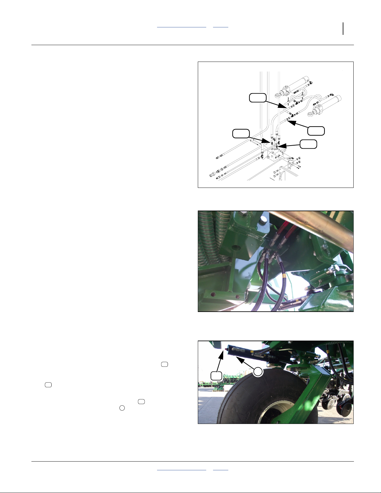
Connect Hoses at Wing Tubes
Refer to Figure 58 (which depicts wings folded for routing
clarity - make these connections prior to first wing fold)
90. Route hoses from lower rack tubes to center section
tubes and rows. In general, the outermost rack tube
is connected to the rear-most section tube. The
center rack tubes connect directly to Y-tube or rows.
Secure with clamps.
91. Route hoses from upper rack tubes to wing tubes.
The outermost rack tube is connected to the rear-most wing tube. Secure with clamps.
2012-08-08 Table of Contents Index 401-647Q
Rack to Wing Tube Hoses
Figure 58
29945
Page 38

34 3PYPA Table of Contents Index Great Plains Manufacturing, Inc.
Connect Air Box Inlet Hose
Install Hose Routing Clamp
Refer to Figure 59, Figure 60 and Figure 61
92. Select two (2) each:
25
403-579D CLAMP, HOSE ROUTE 6 INCH
64
806-192C U-BOLT 5/16-18X1 1/2X2 1/2 RND
and four (4) sets:
59
804-036C WASHER FLAT 5/16 SAE PLT
49
803-084C NUT HEX NYLOCK 5/16-18 PLT
93. Loosely assemble the clamps to the top side of the
top level rack tube that is just right of center. Slide
the clamp down the tube, to a position
7 inches (18 cm) from the rear end of the tubes
(measured from rear edge of clamps to just beyond
hose clamps on tubes).
94. Route the large hose from the lower outlet of the fan
manifold, through the fan frame cradles and the
routing clamp .
95. Locate one (not shown):
31
800-151C CLAMP WRM DRV #96SS (4.75-6.5)
This may be on the hose or in a crate.
96. Add the clamp to the hose. Slide the hose end
onto the air box inlet. Secure with hose clamp.
97. Adjust the routing clamps so that they just keep
the hose from sliding in the clamps. Tighten the lock
49
nuts just enough to keep the clamps from sliding
on the tube. Do not over-tighten the nuts, or the rack
tube may be damaged.
25
31
25
1
49
59
64
Figure 59
Air Box Inlet Hose Clamp
2
1
1
25
25
25
29839
Figure 60
Fan Outlet Hose Route
25
2
25
29949
7 in.
Figure 61
Fan Outlet Hose
401-647Q Table of Contents Index 2012-08-08
29946
Page 39
Great Plains Manufacturing, Inc. Table of Contents Index Planter Assembly 35
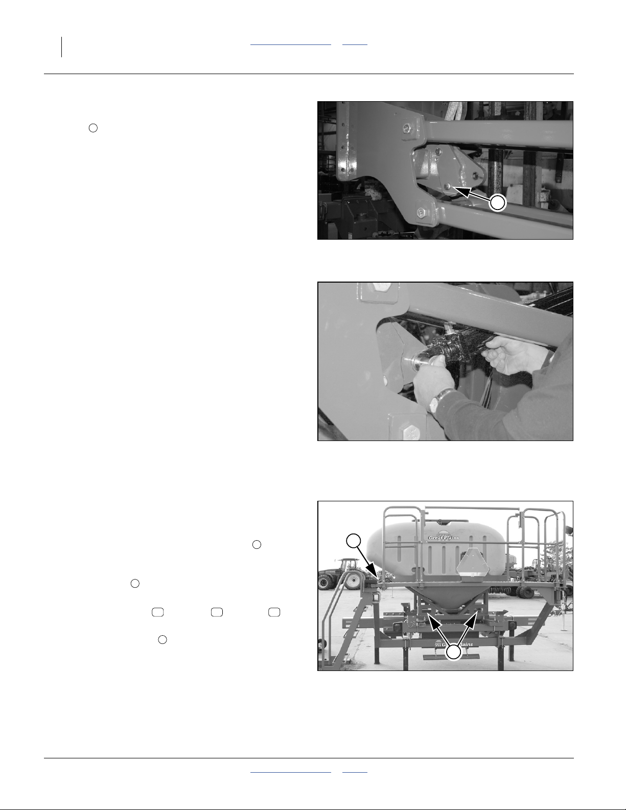
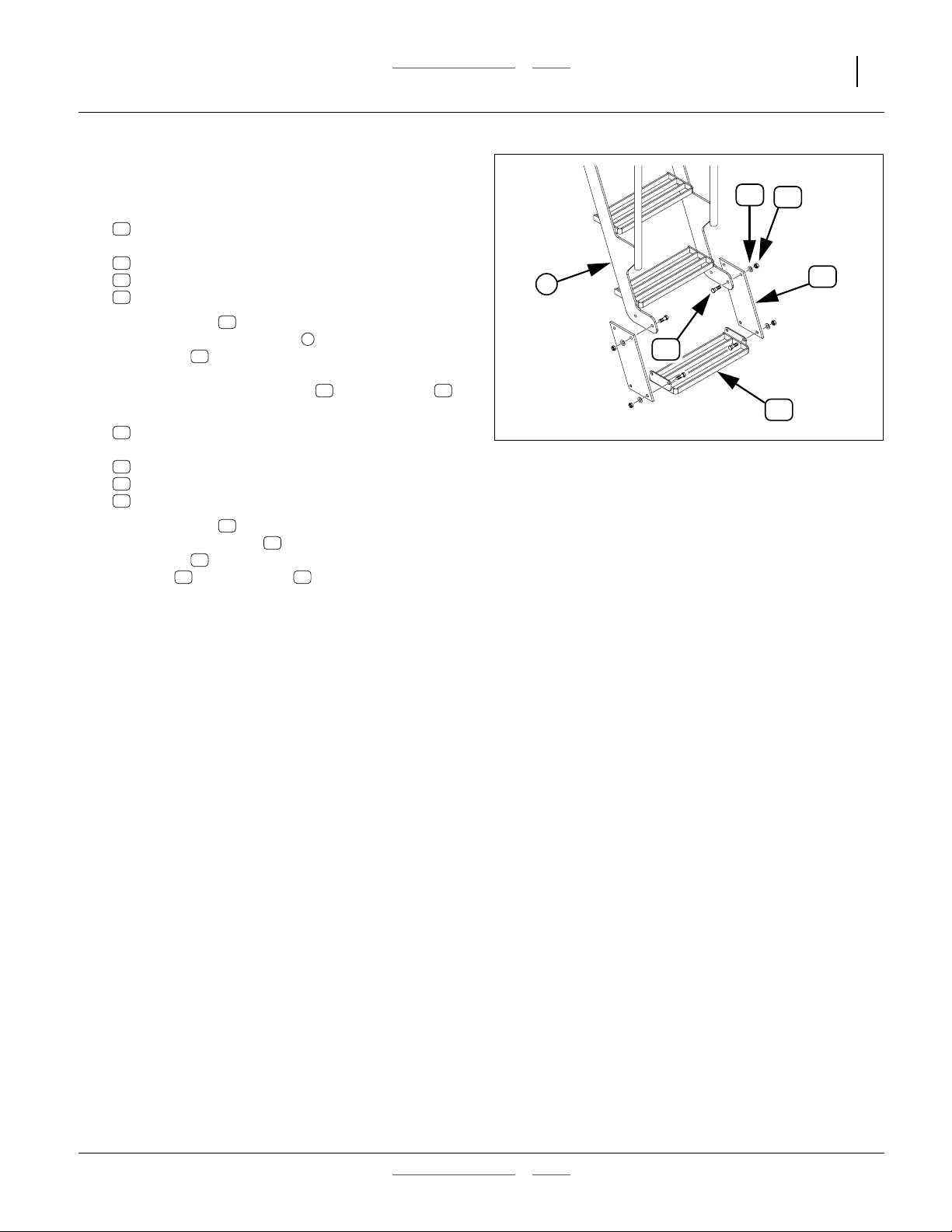
Install Lower Walkboard Step
Refer to Figure 62
98. Select two:
67
816-634C STEP EXTENSION RUBBER
and four (4) sets:
38
802-091C HHCS 1/2-13X1 1/2 GR5
57
804-016C WASHER FLAT 1/2 SAE PLT
45
803-019C NUT LOCK 1/2-13 PLT
99. Insert the bolts from the inside of the bottom four
holes of the existing ladder . Align the rubber
extensions to cant out (following the angle of the
38
3
67
ladder) and place them over the bolt threads.
Loosely secure with washers and lock nuts .
57 45
100. Select one:
18
401-591H STEP SINGLE BOLT-ON
and four (4) sets:
38
802-091C HHCS 1/2-13X1 1/2 GR5
57
804-016C WASHER FLAT 1/2 SAE PLT
45
803-019C NUT LOCK 1/2-13 PLT
101. Insert the bolts from the inside of the bottom four
holes of the new step . Align the rubber
extensions over the bolt threads. Add
washers and lock nuts . Secure all nuts
38
18
67
57 45
(tighten to Grade 2 torque specification).
57
45
3
67
38
18
Figure 62
Step Installation
29104
2012-08-08 Table of Contents Index 401-647Q
Page 40

36 3PYPA Table of Contents Index Great Plains Manufacturing, Inc.
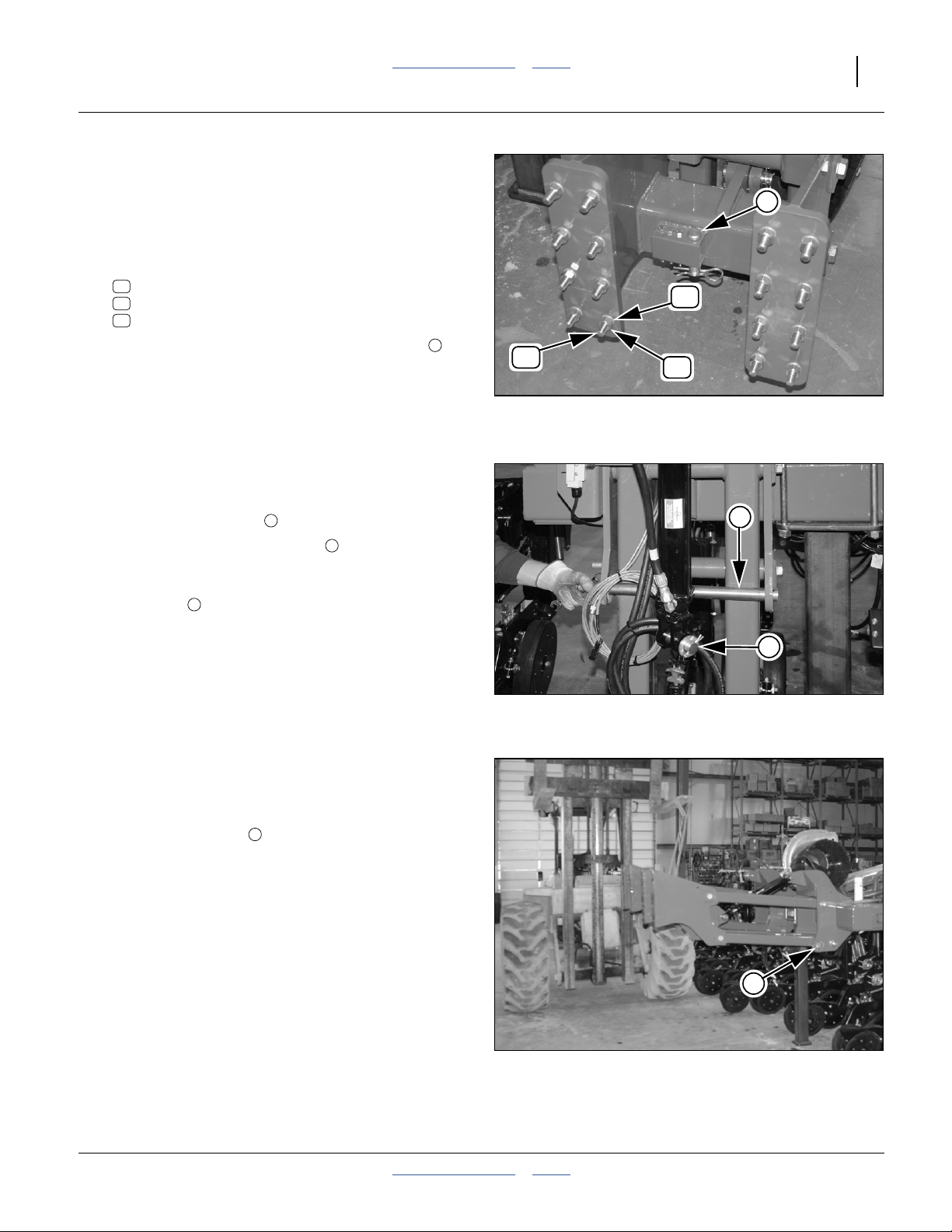
Install Press Wheel Assemblies
Refer to Figure 63 and Figure 64
If any press wheel assemblies were shipped
separately, or removed at step 22, install them now.
Note: With twin row planters, long and short press wheel
arm mount boxes are alternated every other row.
The long box is identified by the notches on its side
plate. The long box belongs on the right hand row
of a set of twins.
102. Remove and save the
and washer at the back of one of the center row
6
units .
Avoid Alignment Disturbance:
There are four bolts at this location. Remove only the hex head
bolts. Do not loosen or remove the square head bolts forward.
103. Remove and save the1⁄2-13 × 11⁄2inch hex head
7
bolt , washer, and eccentric adjuster nut.
104. Align the1⁄2in holes in the press wheel assembly
with the1⁄2-13 tapped holes in the row unit, loosely
assemble with the1⁄2-13 × 1 inch hex head bolt and
washer .
105. Loosely screw in the1⁄2-13 × 11⁄2inch hex head
7
bolt , washer, and eccentric adjuster nut. Rotate
the adjuster to visually align the press wheel
assembly with the row unit, and tight the adjust and
both bolts.
5
5
4
8
1
⁄2-13 × 1 inch hex head bolt
6
7
Figure 63
Press Wheel Installation
8
Figure 64
Notches Identify Long Press
Wheel Box
4
8
5
25383
32191
401-647Q Table of Contents Index 2012-08-08
Page 41

Great Plains Manufacturing, Inc. Table of Contents Index Planter Assembly 37
Install Row Unit Side Wheels
This applies to Model 3PYPA-3115 only. For all other
models, skip to step 110.
On 3PYPA planters with 15-inch single row spacings, the
side depth gauge wheels are left uninstalled on four
rows, to permit the wing gauge wheel to fold under the
wing for shipment.
Refer to Figure 65
106. Select one of the side depth gauge wheels, which
may be one of:
69
814-173C 4 X 16 GAUGE TIRE ASSY-PLASTIC
69
814-257C 2.5X16 SIDE DEPTH WHEEL ASSY
69
814-260C 3X16 SIDE DEPTH WHEEL ASSY
107. Select one each:
42
802-646C HHCS 5/8-11 X 3 GR8
58
804-022C WASHER LOCK SPRING 5/8 PLT
63
804-195C WASHER FLAT 1.31ODX.65IDX.188T
and six (6) each:
60
804-040C WASHER MACH 1.19 X .63 X 18GA
108. Place the lock washer and three (3) of the
machine washers on the bolt . Insert the bolt
assembly through the outside face of the wheel .
109. Add the flat washer and the remaining machine
washers to the bolt. Secure the wheel assembly
to the arm .
60
26
58
60 42
69
63
69
63
58
42
{
60
Figure 65
Side Gauge Wheel Installation
26
{
60
29954
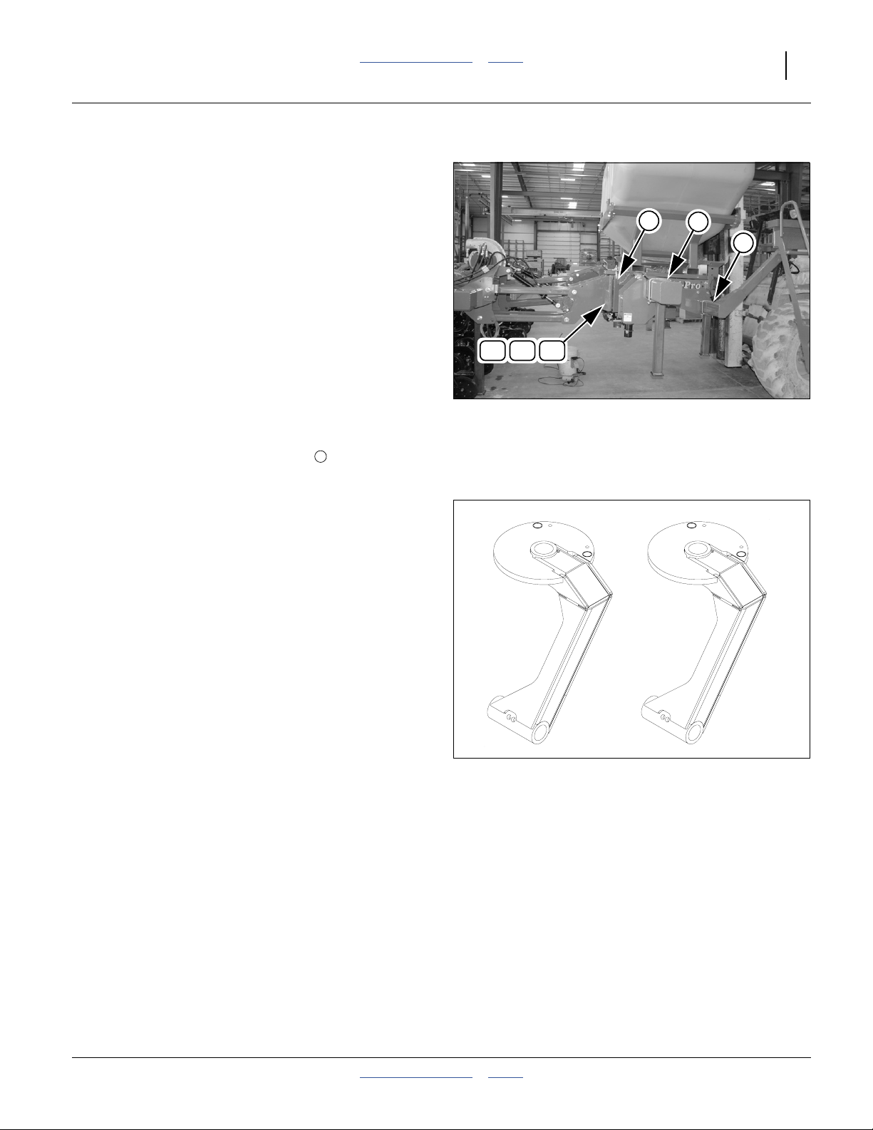
Hopper Installation
Refer to Figure 66
110. If the 82 bushel hopper is included, set it on the
support structure with the slide gate facing to the
rear. Secure it in place with the pins. See Operator
Manual for mounting instructions.
111. If the standard 833-253C level sensor is installed on
the hopper, and a 466820710S3 extension cable is
available, route the extension cable along the
steering hose/cable bundle to the mainframe.
Connect the forward end to the mainframe harness
lead “HOPPER 2”. Secure extension cable to
existing bundle with tie wraps.
112. Close and secure the walkboard.
3
Figure 66
Hopper Sensor Lead
25382
2012-08-08 Table of Contents Index 401-647Q
Page 42

38 3PYPA Table of Contents Index Great Plains Manufacturing, Inc.
Hopper Level Sensor Installation
Regardless of hopper/seed box used, the 3PYPA planter
includes a factory-installed seed level sensor in the
airbox.
If a 403-143K 82 bushel hopper was ordered with the
planter, it includes an 833-235C hopper level sensor
which is not factory-installed. This sensor can provide a
second, earlier, low seed level alarm.
An optional 466820710S3 extension cable is required to
connect the hopper level sensor to the 3PYPA seed
monitor harness.
Use of the hopper level sensor is optional, and level
placement is at your discretion. To install:
113. Perform the installation before first use of the
hopper. The sensor body is mounted inside the
hopper. It can be dangerous to enter a hopper if it
contains any seed, or has ever been used with
treated seed.
114. Refer to Figure 68 for placement elevations based
on remaining hopper capacity. Great Plains
suggests mounting the sensor on the lower front
wall of the hopper.
115. Follow the steps in DICKEY-john®instruction sheet
110011126 to install the sensor.
116. Use silicone to seal the cable at the grommet, and
around the grommet, to prevent air leaks which can
interfere with consistent seed delivery.
117. Connect the sensor lead to the harness installed at
step 111 on page 37.
Figure 67
833-235C Hopper Level Sensor
Approximate capacity of bulk seed hopper,
in bushels, at 10 inch increments
29328
Figure 68
Hopper Capacity (bushels)
29869
Row Unit Options
Optional row unit capabilities that are not
factory-installed include their own installation
instructions, or rely on instructions in the planter
Operator manual.
401-647Q Table of Contents Index 2012-08-08
Page 43

Great Plains Manufacturing, Inc. Table of Contents Index Planter Assembly 39
Planter Closeout
118. Using the lift assist cylinders, lift the planter and
remove the rear main frame shipping stand. Save it
for customer use.
Emergency Moves Without Steering
To move the planter with a tractor lacking 3PYPA planter
steering components, or to move a planter with a
steering system malfunction, the casters must be in
Float. Steps below describe methods for several
situations.
Force Caster Float
Any of these configurations will float the casters.
1. Normal Caster Float
(for forward travel only - do not back up)
a. Shut off tractor. Power-Beyond cannot be
connected with tractor running.
b. Make all normal hydraulic and electrical
connections, including steering. Start tractor.
c. Set “STEER” switch on steering switch box OFF.
d. If casters do not float, try step 2.
Steering Not Yet Set Up:
The planter is now safe to move, forward only, or hitch to any
3-point tractor of sufficient capability. Make no reverse moves
until hitched to the tractor on which the steering sensor is
installed.
Equipment Damage Risk:
Make only careful forward moves with casters in Float. With
options 1- 3, do not make reverse moves. The casters
immediately swivel to a hard turn state, usually opposite to
any tractor turn. Damage to planter and tractor is likely.
2. ECU-Disconnected Caster Float
(for forward travel only - do not back up)
a. Shut off tractor. Power-Beyond cannot be
connected with tractor running.
b. Make all normal hydraulic connections, including
steering. Start tractor.
c. Make all normal electrical connections, EXCEPT
steering.
3. Mechanical Float
(for forward travel and for backing up)
a. Remove 11⁄4inch pin locking the caster
weldment and steering arm weldment together.
b. Make all normal hydraulic and electrical
connections EXCEPT power beyond pressure
line.
2012-08-08 Table of Contents Index 401-647Q
Page 44

40 3PYPA Table of Contents Index Great Plains Manufacturing, Inc.
Console Installation
If the tractor to be used with this planter is not available
prior to customer delivery, provide this manual to the
customer for installation of the console.
Seed Monitor Console Installation
The planter’s standard seed monitor system includes a
virtual terminal and switch panel that must be mounted in
the tractor cab. As supplied by DICKEY-john®, the kit
includes a flat bracket for the modules, and a ball swivel
for mounting the bracket in the tractor.
Transport and Field Safety Risk:
Mount the modules so that they are easy to monitor during
planting, but do not interfere with safe operation of the tractor
in the field or on public roads.
The ball swivel includes four 10-32 screws. You or your
dealer must provide the mounting holes for the screws.
Your dealer may have alternate suction cup or clamping
brackets available if you prefer to avoid drilling holes.
Refer to the included DICKEY-john®manual for harness
connections.
Figure 69
Terminal and Switch Panel
26303
401-647Q Table of Contents Index 2012-08-08
Page 45

Great Plains Manufacturing, Inc. Table of Contents Index 41
p74p
Tractor Steering
Integration of tractor steering and planter steering is
required. The tractor must be a model listed under
“Compatible Tractors” on page 5, and must meet the
requirements listed under Specifications and Capacities,
“Appendix A - Reference Information” on page 64.
Seed cart steering is hydraulically controlled to match
steering of the tractor based on data from a steering
sensor.
There are five sensor data configurations. All require
some optional hardware. See table below.
If the tractor is not have one of the brands and models
listed, consult your Great Plains dealer. At time of
publication, this 3PYPA planter steering system is not
compatible with articulated tractors.
Steering Signal Source Requires Description
Great Plains linear sensor
a
Tractor ISObus data
Case IH® tractor steering sensor
John Deere® tracked tractor steering sensor
John Deere® wheeled tractor steering sensor
a. Additional tractor-specific mounting hardware is included with the standard planter.
401-748A
401-747A
401-747A
833-544C
401-747A
833-546C
401-747A
833-548C
LINEAR STEERING SENSOR OPT
HARNESS ASY STEER SNSR ADAPTOR
HARNESS ASY STEER SNSR ADAPTOR
HARNESS CNH WHEEL ANGLE SENSOR WHEEL TYPE
HARNESS ASY STEER SNSR ADAPTOR
HARNESS JD WHEEL ANGLE SENSOR TRACK TYPE
HARNESS ASY STEER SNSR ADAPTOR
HARNESS JD WHEEL ANGLE SENSOR WHEEL TYPE
Install Switchbox
70p
Refer to Figure 70
The switchbox is used in all sensor configurations.
4. Select one:
70
833-437C SWITCH CAB
70
70s
Mount the switchbox in any convenient location
70
that allows easy access to switches in the field,
observation of fault indications, and does not
obstruct safe operation of the tractor. Set the
STEER switch to Off.
5. Connect the battery power leads to an
70b
unswitched 12Vdc source. Red+, Black-.
6. Route the main harness to the hitch, where it
70h
mates with the Steering ECU harness from the
planter.
The next step depends on the tractor steering signal
70b
70
Figure 70 833-437C
Steering Switch Box & Harness
Lead Function
70h
31783
source:
Ring tongue terminals: 12Vdc Battery Power in
• For a Great Plains linear sensor, continue at “Install
GP Linear Sensor” on page 42.
• For a tractor ISObus signal source, or native tractor
steering sensor, continue at “Install Electronic
Module” on page 51.
2012-08-08 Table of Contents Index 401-647Q
70b
10-pin: Steering Harness to Hitch
70h
3-pin: normalized PWM steering sensor input
70s
(from linear sensor or electronic module)
3-pin (2 used): Power out to harness
70
Page 46

42 3PYPA Table of Contents Index Great Plains Manufacturing, Inc.
Install GP Linear Sensor
The linear sensor is installed when not using native
tractor steering sensor or CANbus steering data.
Major subassemblies to install are:
• tractor steering sensor , with brand-model-specific
brackets, which detects tractor wheel pointing; and
• the cab steering switch console which controls
operation and calibration of the steering system.
81
81
70
89
84
88
88
87
87
95
85
88
Case IH MX
90
86
90
Components are not Universal:
Install only on listed tractors (page 5).
Contact Great Plains if any fitting issues are encountered.
Note: The parts illustrated and listed below are supplied
for tractor installation. Only two of the six provided
“BRKT SENSOR” brackets are used, depending
on tractor brand and model.
92
83
93
81
Deere RFS
82
Deere ILS
94
Figure 71
Steering Components for Tractor
Linear Sensor Parts
Callout Part Number Descriptor Comment
401-748A
81 401-541S
82 411-575D
83 411-580D
84 411-581D
85 411-582D
86 802-097C
87 802-167C
88 803-255C
89 803-305C
90 804-007C
91 833-438C
Parts included with planter
92 411-576D
93 411-577D
94 411-578D
95 411-579D
LINEAR STEERING SENSOR OPT
SENSOR LIN
BRKT SENSOR JD FIXED
BRKT SENSOR ROD END CASE MX
COLLAR
YOKE
HHCS 1/4-20X2 1/2 GR5
HHCS 1/4-20X1 1/2 GR5
NUT HEX NYLOCK 1/4-20
NUT HEX NYLOCK 3/8-24 PLT
WASHER FLAT 1/4 SAE PLT
HARNESS TRACTOR POSITION
BRKT SENSOR JD WHL
BRKT SENSOR JD SUSPEN FIXED
BRKT SENSOR JD SUSPEN WHL
BRKT SENSOR BASE TRACTOR
for John Deere® 8000 rigid front suspension (RFS)
for Case IH® MX/Magnum™
for John Deere® 8000 rigid front suspension (RFS)
for John Deere® 8000 ILS
for John Deere® 8000 ILS
for Case IH® MX/Magnum™
29202
401-647Q Table of Contents Index 2012-08-08
Page 47

Great Plains Manufacturing, Inc. Table of Contents Index Tractor Steering 43
Assemble Tractor Sensor
Refer to Figure 72
If the sensor is pre-assembled, loosen collar bolt and
skip to step 13.
7. Select one each:
85
411-582D YOKE
87
802-167C HHCS 1/4-20X1 1/2 GR5
90
804-007C WASHER FLAT 1/4 SAE PLT
8. Insert the shorter bolt into the flat washer ,
and then into the yoke from the lug side.
87 90
85
9. Select one each:
84
411-581D COLLAR
86
802-097C HHCS 1/4-20X2 1/2 GR5
88
803-255C NUT HEX NYLOCK 1/4-20
10. Align yoke side holes with collar base holes
and insert bolt . Secure with lock nut . Tighten
85 84
86 88
to allow free pivoting of the yoke with little or no
side-to-side slack.
11. Select one each:
81
401-541S SENSOR LIN
Gently extend the rod to full length. Measure and
record the overall length of the sensor. Gently push
the rod fully into the cylinder sleeve. Measure and
record the overall length. Add those measurement
and divide by 2. Record this [centered] length.
CenteredLength
MaxLength MinLength+
------------------------------------------------------------=
2
87
88
1 inch (2.5 cm)
84
81
87
88
87
85
90
86
Figure 72
Tractor Steering Sensor Assembly.
Equipment Damage Risk:
Handle the linear displacement sensor carefully.
81
It is a precision instrument.
Note: Final collar position is determined at installation.
29203
12. Select one each:
87
802-167C HHCS 1/4-20X1 1/2 GR5
88
803-255C NUT HEX NYLOCK 1/4-20
13. Slide collar about 1 inch (2.5 cm) onto base end
of sensor , with vent hole near cylinder base
pointing down, and loosely secure with bolt and
lock nut through collar clamp holes.
84
81
87
88
Install Tractor Steering Sensor
Instructions for the next step depend on the brand and
model of tractor:
Case IH MX or Magnum Skip to “Case IH® MX/Magnum™ Installation” on page 44.
John Deere 8000 Series RFS Skip to “John Deere® 8000 (RFS) Installation” on page 46.
John Deere 8000 Series ILS Skip to “John Deere® 8000 ILS Installation” on page 48.
2012-08-08 Table of Contents Index 401-647Q
Page 48

44 3PYPA Table of Contents Index Great Plains Manufacturing, Inc.
Case IH® MX/Magnum™ Installation
Refer to Figure 73 and Figure 74
The sensor is installed at the forward top of the left
front axle.
14. Turn the tractor to the left to open room to work.
15. Select one:
95
Case IH
Refer to Figure 74
16. Remove the existing forward bolt .
Loosen the rear bolt .
17. Insert the long tab of the bracket with the short
tab facing left. If possible, align the inner hole
under the tractor bolt hole. If not possible, use the
end hole . Secure with removed bolt .
Case IH
Refer to Figure 73 and Figure 75 on page 45
18. Select one:
83
19. Remove existing bolt . Using that bolt, secure the
short tab (with the larger holes) of the bracket
with the long tab facing forward and right. Use the
corner large hole for the initial trial mounting.
20. It may be necessary to use the alternate large
hole when the sensor is fitted in the next steps.
Case IH®: Check Sensor Extension
21. Turn the tractor front wheels straight ahead. Shut off
tractor.
22. Select the sensor assembly . Loosen the gimbal
collar . Gently pull the sensor rod to centered
extension, as determined at step 11 on page 43,
with yoke center bolt down, and rod-end bolt up.
Note: When trial fitting, make sure sensor does not
23. Determine which bracket holes sensor fits. Mark
those holes, but do not mount the sensor at this
time. At the inboard end, use the left tab hole if
possible.
81
411-579D BRKT SENSOR BASE TRACTOR
®
: Mount Inside (Base End) Bracket
a
b
95
4
®
: Mount Outside (Rod End) Bracket
411-580D BRKT SENSOR ROD END CASE MX
c
7
8
81
84
contact any tractor components. Use alternate
mount and pivot holes as necessary to obtain
clearance.
a
3
83
5
95
8
7
89
84
83
9
3
4
81
87
90
5
88
6
Figure 73
Case IH® Components
b
a
29202
95
Figure 74
Case IH®/MX Inboard Bracket
29208
If sensor is too short, move collar toward connector
end (base) of sensor. Do not block vent hole.
If sensor is too long, move outboard bracket to
alternate mounting hole. If sensor is still too long,
move collar toward rod end of sensor.
Note holes and collar position with a marker.
401-647Q Table of Contents Index 2012-08-08
83
Page 49

Great Plains Manufacturing, Inc. Table of Contents Index Tractor Steering 45
24. Remove the sensor assembly. Check that vent hole
is unobstructed and facing down. Tighten bolt at
top of collar to Grade 2 torque specification.
25. Turn the tractor front wheels fully to the left. Shut off
87
84
c
81
tractor.
26. Using marked holes and collar position, extend
89
sensor rod until rod end bolts align with marked
holes. Measure the overall length of the sensor. It
must be at least3⁄8inch (1 cm) shorter than the
maximum length (and can be substantially less than
that).
83
27. Turn the tractor front wheels fully to the right. Shut
off tractor.
28. Using marked holes and collar position, extend
sensor rod until rod end bolts align with marked
holes. Measure the overall length of the sensor. It
must be at least3⁄8inch (1 cm) longer than the
minimum length (and can be substantially more
Figure 75
Case IH®/MX Outboard Bracket
29204
than that).
Install to Specification Only:
If it is not possible to obtain reserve lengths of at least
3
⁄8inch (1 cm) at full left and right turn, have your Great
Plains dealer consult the factory. Insufficient reserve will
result in sensor damage.
Case IH®: Mount Sensor
Refer to Figure 73 (page 44) and Figure 75
29. Select the sensor assembly , and one each:
88
803-255C NUT HEX NYLOCK 1/4-20
90
804-007C WASHER FLAT 1/4 SAE PLT
Place the flat washer on the lower yoke bolt.
81
90
Insert the bolt, from above, through the marked hole
at the inboard bracket. Secure with lock nut .
88
Tighten to allow lateral pivoting but not rocking of
gimbal assembly.
30. Select one:
89
803-305C NUT HEX NYLOCK 3/8-24 PLT
Insert the threaded rod-end bolt, from below,
through the marked hole in the outboard bracket.
Secure with lock nut to Grade 2 torque spec.
89
31. Resume at “Install Harness for Linear Sensor”on
page 50.
2012-08-08 Table of Contents Index 401-647Q
Page 50

46 3PYPA Table of Contents Index Great Plains Manufacturing, Inc.
John Deere® 8000 (RFS) Installation
Refer to Figure 76 and Figure 77
The sensor is installed at the forward top of the left
front axle.
32. Turn the tractor to the left to open room to work.
JD RFS: Mount Inside (Base End) Bracket
33. Select one:
82
34. Remove the existing bolt . With the short tab of
the bracket (bracket hole ) facing to the right
and down, insert the removed bolt and re-secure to
tractor.
JD RFS: Mount Outside (Rod End) Bracket
35. Select one:
92
36. Remove existing bolts . Using the same bolts,
secure the long tab (with larger holes ) of the
bracket with the short tab facing forward/right.
JD RFS: Check Sensor Extension
37. Turn the tractor front wheels straight forward. Shut
off tractor.
38. Select the sensor assembly . Loosen the gimbal
collar . Gently pull the sensor rod to centered
extension, as determined at step 11 on page 43,
with yoke center bolt down, and rod-end bolt up.
Note: When trial fitting, make sure sensor does not
39. Determine which bracket holes sensor fits. Mark
those holes, but do not mount the sensor at this
time. At the inboard end, use the left end tab hole
if possible. At the outboard end, use center tab
hole if possible.
81
411-575D BRKT SENSOR JD FIXED
a
82 3
411-576D BRKT SENSOR JD WHL
b
4
92
81
84
contact any tractor components. Use alternate
mount and pivot holes as necessary to obtain
clearance.
8
4
92
4
84
89
9
8
9
81
87
82
90
5
88
3
John Deere® (RFS) Components
84
5
82
6
Figure 76
81
29202
b
b
89
If sensor is too short, move collar toward connector
end (base) of sensor. Do not block vent hole. If
sensor is still too short, use an alternate hole at
outboard bracket.
If sensor is too long, move collar toward rod end of
sensor.
Note holes and collar position with a marker.
Note: Sensor will tilt up slight from inboard to outboard.
40. Remove the sensor assembly. Check that vent hole
is unobstructed and facing down. Tighten bolt at
top of collar to Grade 2 torque specification.
41. Turn the tractor front wheels fully to the left. Shut off
tractor.
401-647Q Table of Contents Index 2012-08-08
9
92
a
Figure 77
John Deere® RFS Installation
87
29205
Page 51

Great Plains Manufacturing, Inc. Table of Contents Index Tractor Steering 47
42. Using marked holes and collar position, adjust
sensor rod until yoke and rod-end bolts align with
marked holes. Measure the overall length of the
sensor. It must be at least3⁄8inch (1 cm) shorter
than the maximum length (and can be substantially
less than that).
43. Turn the tractor front wheels fully to the right. Shut
off tractor.
44. Using marked holes and collar position, extend
sensor rod until rod end bolts align with marked
holes. Measure the overall length of the sensor. It
must be at least3⁄8inch (1 cm) longer than the
minimum length (and can be substantially more
than that).
Install to Specification Only:
If it is not possible to obtain reserve lengths of at least
3
⁄8inch (1 cm) at full left and right turn, have your Great
Plains dealer consult the factory. Insufficient reserve will
result in sensor damage.
JD RFS: Mount Sensor
Refer to Figure 76 and Figure 77 (both page 46)
45. Select the sensor assembly , and one each:
88
803-255C NUT HEX NYLOCK 1/4-20
90
804-007C
WASHER FLAT 1/4 SAE PLT
Place the flat washer on the lower yoke bolt.
81
90
Insert the bolt, from above, through the marked hole
at the inboard bracket. Secure with lock nut .
88
Tighten to allow lateral pivoting but not rocking of
gimbal assembly.
46. Select one:
89
803-305C NUT HEX NYLOCK 3/8-24 PLT
Insert the threaded rod-end bolt, from below,
through the marked hole in the outboard bracket.
Secure with lock nut to Grade 2 torque spec.
89
47. Resume at “Install Harness for Linear Sensor”on
page 50.
2012-08-08 Table of Contents Index 401-647Q
Page 52

48 3PYPA Table of Contents Index Great Plains Manufacturing, Inc.
John Deere® 8000 ILS Installation
Refer to Figure 78 and Figure 79
The sensor is installed at the rear of the right front
axle, close to the drive shaft.
48. Turn the tractor to the left to open room to work.
JD ILS: Mount Inside (Base End) Bracket
49. Select one:
94
50. Loosen the existing bolt just aft and lower at the
inboard universal joint. Slide the bracket tab with the
open slotted hole under the bolt head. Align so the
other tab is up and horizontal. Re-secure bolt .
JD ILS: Mount Outside (Rod End) Bracket
Refer to Figure 78 and Figure 80 on page 49
51. Select one:
93
52. Remove the existing bolt . Using the same bolt,
secure the long tab (with the larger hole) of the
bracket with the short tab facing forward and
right.
53. Turn the tractor front wheels straight forward.
Shut off tractor.
JD ILS: Check Sensor Extension
54. Select the sensor assembly . Loosen the gimbal
collar . Gently pull the sensor rod to centered
extension, as determined at step 11 on page 43,
with yoke center bolt down, and rod-end bolt up.
Note: When trial fitting, make sure sensor does not
55. Determine which bracket holes sensor fits. Mark
those holes, but do not mount the sensor at this
time. At the inboard end, use the left end tab hole
if possible. At the outboard end, use center tab
hole if possible.
81
411-578D BRKT SENSOR JD SUSPEN WHL
a
a
411-577D BRKT SENSOR JD SUSPEN FIXED
a
93
81
84
contact any tractor components. Use alternate
mount and pivot holes as necessary to obtain
clearance.
8
89
4
93
84
9
8
81
6
87
94
90
5
3
88
Figure 78
John Deere® ILS Components
94
84
29202
81
88
5
a
If sensor is too short, move collar toward connector
end (base) of sensor. Do not block vent hole. If
sensor is still too short, use alternate hole at
outboard bracket.
If sensor is too long, move collar toward rod end of
sensor.
Note holes and collar position with a marker.
Note: Sensor will tilt up slight from inboard to outboard.
401-647Q Table of Contents Index 2012-08-08
9
John Deere® ILS Installation,
Figure 79
Inboard
29206
Page 53

Great Plains Manufacturing, Inc. Table of Contents Index Tractor Steering 49
56. Remove the sensor assembly. Check that vent hole
is unobstructed and facing down. Tighten bolt at
top of collar to Grade 2 torque specification.
87
2
57. Turn the tractor front wheels fully to the right.
Shut off tractor.
58. Using marked holes and collar position, adjust
93
sensor rod until yoke and rod-end bolts align with
marked holes. Measure the overall length of the
sensor. It must be at least3⁄8inch (1 cm) shorter
than the maximum length (and can be substantially
less than that).
81
59. Turn the tractor front wheels fully to the right. Shut
off tractor.
89
60. Using marked holes and collar position, extend
sensor rod until rod end bolts align with marked
holes. Measure the overall length of the sensor. It
must be at least3⁄8inch (1 cm) longer than the
minimum length (and can be substantially more
than that).
Figure 80
John Deere® ILS Installation,
Outboard
29207
Install to Specification Only:
If it is not possible to obtain reserve lengths of at least
3
⁄8inch (1 cm) at full left and right turn, have your Great
Plains dealer consult the factory. Insufficient reserve will
result in sensor damage.
JD ILS: Mount Sensor
Refer to Figure 78, 79 (page 48) and Figure 80
61. Select the sensor assembly , and one each:
88
803-255C NUT HEX NYLOCK 1/4-20
90
804-007C WASHER FLAT 1/4 SAE PLT
Place the flat washer on the lower yoke bolt.
81
90
Insert the bolt, from above, through the marked hole
at the inboard bracket. Secure with lock nut .
88
Tighten to allow lateral pivoting but not rocking of
gimbal assembly.
62. Select one:
89
803-305C NUT HEX NYLOCK 3/8-24 PLT
Insert the threaded rod-end bolt, from below,
through the marked hole in the outboard bracket.
Secure with lock nut to Grade 2 torque spec.
89
2012-08-08 Table of Contents Index 401-647Q
Page 54

50 3PYPA Table of Contents Index Great Plains Manufacturing, Inc.
Install Harness for Linear Sensor
Refer to Figure 82 and Figure 81
The harness is only used if the Great Plains linear
sensor is used . This page does not apply to
91
81
configurations using the tractor’s own steering sensor, or
tractor CANbus steering data.
63. At the tractor steering sensor just installed,
81
remove the plastic cap protecting the connector at
the inboard end.
64. Select one:
91
833-438C HARNESS TRACTOR POSITION
Connect the round connector of the tractor
sensor harness to the output of the linear
steering sensor .
91
81
91a
81a
Refer to Figure 82 and Figure 83
65. Route the steering harness to the rear hitch.
Mate the 3-pin weatherpak connector to
switchbox harness sensor input connector .
91
91s
70s
Allow slack at sensor for steering and vertical axle
movement (if possible). Keep cable clear of hot parts and
moving parts of tractor. Route cable through center-line
of any pivot points.
Allow slack at hitch for hitch movement.
Secure harnesses with cable ties.
Continue at “Steering Calibration” on page 59.
81a
91s
91
91
91a
Figure 81
Linear Steering Harness & Sensor
Figure 82 833-438C
Linear Harness
81
29208
91a
32121
Lead Function
3-pin round:
91a
input from linear sensor
3-pin weatherpak:
91s
output to master harness lead
81
70s
Figure 83
Sensor Input Lead
74r
31783
401-647Q Table of Contents Index 2012-08-08
Page 55

Great Plains Manufacturing, Inc. Table of Contents Index Tractor Steering 51
p74p
Install Electronic Module
Refer to Figure 84
This module is used in configurations that take
ISObus steering data, or native tractor steering sensor
data. It is not used with the Great Plains linear sensor.
66. Select one:
71
The electronic module reads the steering angle
information from either the CANbus or from the tractor’s
own sensor, and converts the information to a PWM
(percent duty cycle) signal that emulates the Great
Plains linear sensor, then outputs the signal to the
planter steering system.
Place the electronic module in a location in the tractor
cab where:
• the front face can be accessed for observation during
some diagnostics,
• it will not get damaged, and;
• it is close enough to the System Switch Box to
mate the power leads ( and ).
71
833-541C SENSOR MODULE WHEEL ANGL
71
70
70
71
71i
Figure 84 833-541C
Electronic Sensor Module
Port Function
12-pin Gray: Input
71i
12-pin Black: Output
71o
71o
31832
2012-08-08 Table of Contents Index 401-647Q
Page 56

52 3PYPA Table of Contents Index Great Plains Manufacturing, Inc.
p70p
p70p
Install Gray Module Harness
The gray (input) module harness is used in
74G
configurations that take ISObus steering data, or native
tractor steering sensor data. It is not used with the Great
Plains linear sensor.
Not all of the leads are connected, and only two are
connected at this step.
Refer to Figure 85, and Figure 86
67. From the harness set:
74
833-547C HARNESS CANBUS STEERING MODULE
select the cable with the Gray 12-pin Deutsch
74G
connector.
Plug the Gray 12-pin Deutsch lead into the
Gray input port receptacle of the sensor
module .
71
Connect the power input lead to the switch box
74G
71i
74
power output lead .
74c
74r
74G
Figure 85
Gray Module Harness
Signal / Power IN
Lead Function
9-pin (2 used): CANbus from tractor
74c
ISO 11786 port (if used)
12-pin: data to sensor module input
74G 71i
3-pin (2 used): power from console
74
3-pin: input from tractor wheel angle sensor
74r
harness , or (if used)
72r 73r 75r
74G
74p
31833
Continue at one of:
• If using native CANbus steering data, continue at
“ISObus Compatible Connection” on page 53.
• If using the tractor’s existing (native) steering sensor,
continue at “Install Harness for Native Steering
Sensor” on page 54.
70
71i
70p
74p
Figure 86
Switchbox , Module ,
70
Gray Module Harness
71
74G
71
74G
31840
401-647Q Table of Contents Index 2012-08-08
Page 57
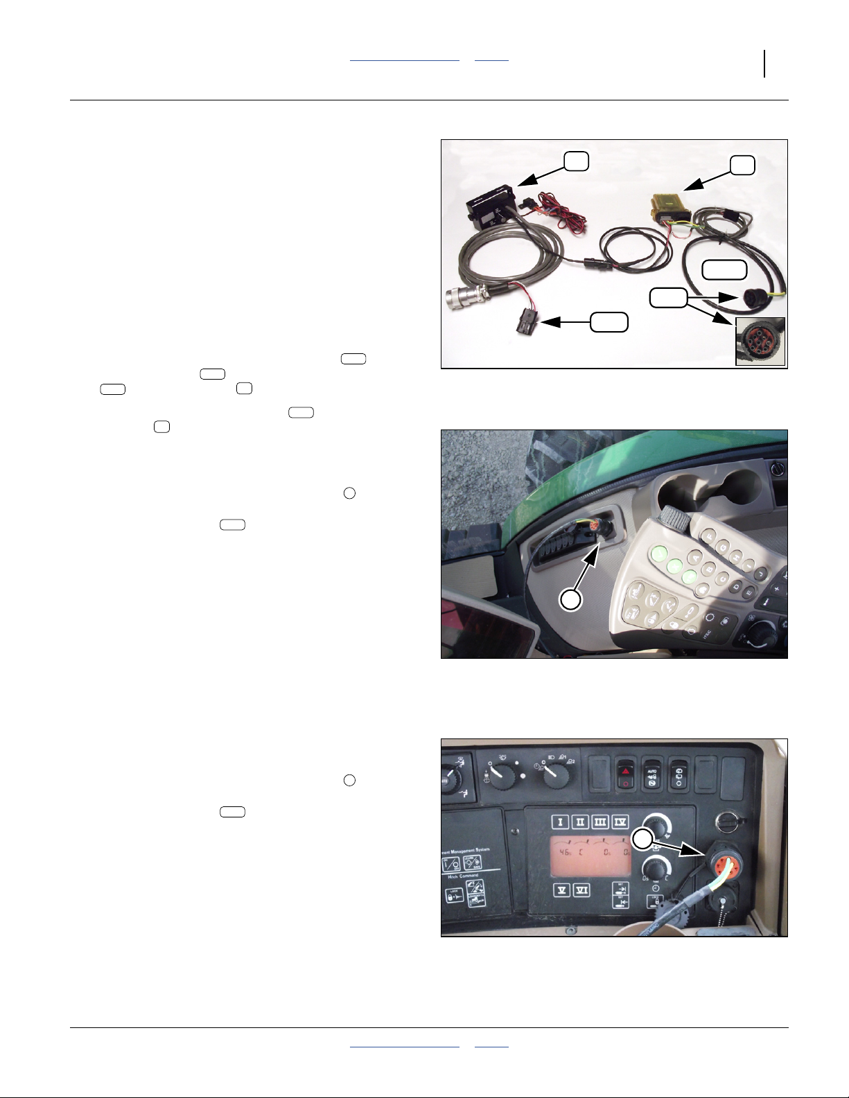
Great Plains Manufacturing, Inc. Table of Contents Index Tractor Steering 53
ISObus Compatible Connection
This connection is used only where ISObus steering data
is used. It is not used with the Great Plains linear sensor,
nor with taking native tractor steering sensor data.
The planter steering system can take CANbus/ISObus
steering data on the following tractor models:
• John Deere® R-Series (except tracked)
• John Deere® 8000 Series
This configuration requires no optional sensor or
harness.
Refer to Figure 87
In this configuration, the CANbus connector on the
gray master harness is used, and the sensor input
lead on the switchbox harness is unused.
70s
68. Locate the CANbus connector on the master
harness .
74
74G
70
74c
74c
70
74c
70s
Figure 87
Master Harness for CANbus
71
74G
31840
31819
John Deere® R-Series ISObus
Refer to Figure 88
69. Locate the ISO 11786 Diagnostics Port on the
right side console. Plug the master harness
CANbus connector into this port.
Continue at “Install Module Output Harness” on
page 58.
74c
1
John Deere® 8000 Series ISObus
Refer to Figure 89
70. Locate the ISO 11786 Diagnostics Port on the
right side console. Plug the master harness
CANbus connector into this port.
Continue at “Install Module Output Harness” on
page 58.
74c
2
1
Figure 88
John Deere® R Series Tractor
ISObus Port
2
31849
Figure 89
John Deere® 8000 Tractor
ISObus Port
2012-08-08 Table of Contents Index 401-647Q
31821
Page 58
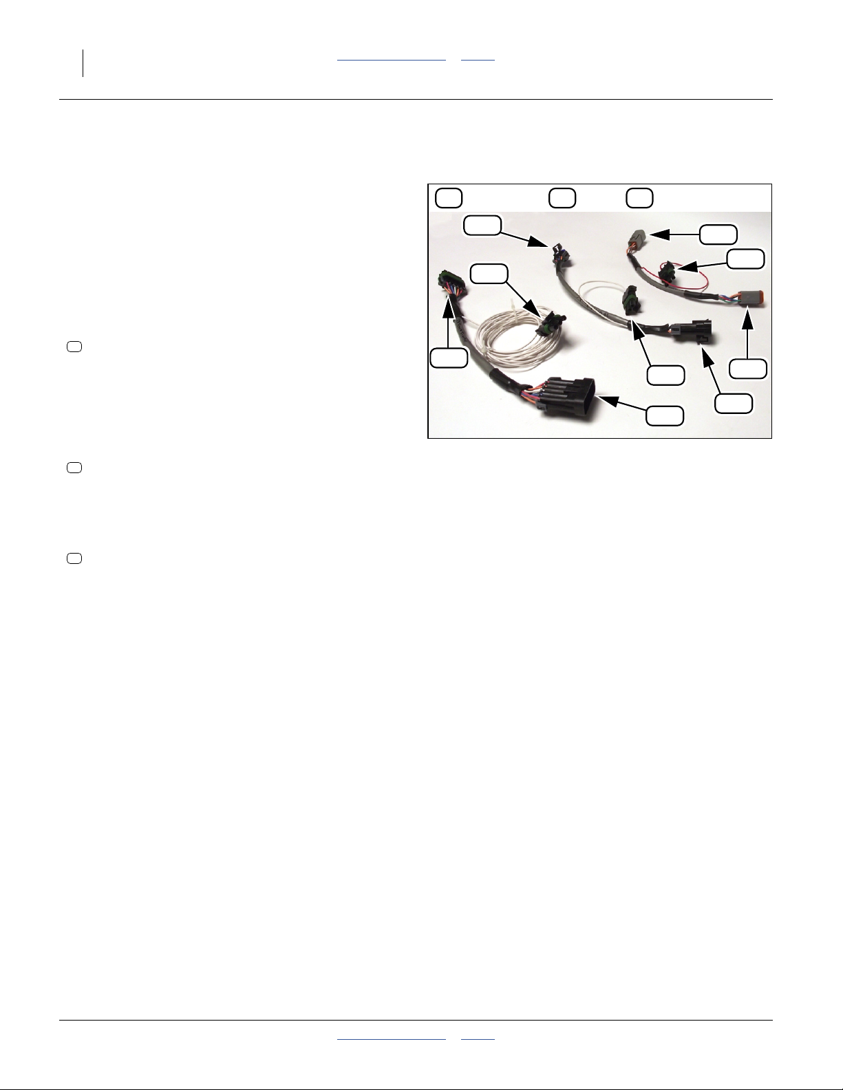
54 3PYPA Table of Contents Index Great Plains Manufacturing, Inc.
Install Harness for Native Steering Sensor
One of the following harnesses, ordered separately, is
used only when the tractor’s own (native) wheel angle
sensor (raw sensor data) is used for planter steering.
These harnesses are not used when the Great Plains
linear sensor is used, nor when CANbus steering data is
used.
Refer to Figure 90
71. Locate and select one of, and continue at the page
indicated:
833-544C
72
HARNESS CNH WHEEL ANGLE SENSOR WHEEL TYPE
for Case/New Holland Wheel Tractors - required for
all Case and New Holland tractors that are factory
equipped as auto-steer ready or have factory
installed auto-steer.
Continue at “Case or New Holland Native Sensor
Harness” on page 55.
833-546C
73
HARNESS JD WHEEL ANGLE SENSOR TRACK TYPE
for John Deere® Track Tractors - required for all
John Deere® tracked tractors.
Continue at “John Deere® Wheeled Native
Sensor Harness” on page 57.
833-548C
75
HARNESS JD WHEEL ANGLE SENSOR WHEEL TYPE
for John Deere® Wheel Tractors - required for
non-ISO compatible John Deere® wheeled
tractors.Continue at “John Deere®Tracked Native
Sensor Harness” on page 56.
73 75 72
75b
73r
73b
Figure 90
Optional Adaptor Harnesses
75r
73a
72b
72r
72a
75a
31816
401-647Q Table of Contents Index 2012-08-08
Page 59
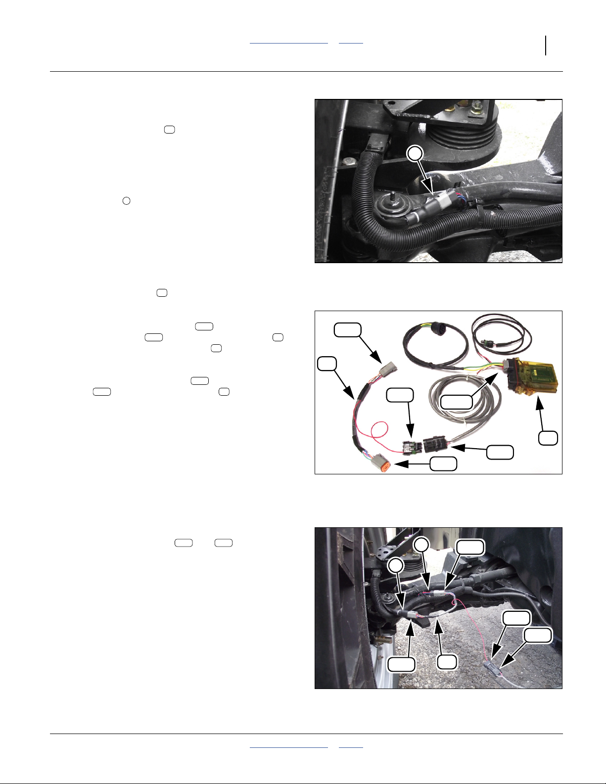
Great Plains Manufacturing, Inc. Table of Contents Index Tractor Steering 55
Case or New Holland Native Sensor Harness
Optional adaptor harness for Case/New Holland
wheeled tractors is necessary when the tractor wheel
angle signal cannot be obtained from the CANbus on the
tractor.
Refer to Figure 91 and Figure 92
72. Locate the tractor Wheel Angle Sensor harness
connectors , on the left side of the tractor
positioned just behind the axle and wheel kingpin.
They are inside a plastic wire protector.
• Peel back the wire protector.
• Disconnect the wheel sensor harness
(see Figure 91).
• Reconnect the disconnected leads using the
adaptor harness .
Refer to Figure 92 and Figure 93
73. Route the sensor input lead of the master
module harness from the sensor module in
the cab, to the adaptor harness just installed at
step 72.
Mate the sensor input lead to the sensor tap
lead on the adaptor harness .
1
72r
74G
72
72
74r
74r
72
72
71
72
72b
1
Figure 91
Case Tractor LH Axle
72r
74G
31853
Refer to Figure 93
74. Dress the sensor leads and along existing
harnesses, tubing, hoses and tractor fittings. Allow
slack near moving parts, routing through pivot
center-lines where possible. Avoid hot parts. Protect
the harness against strikes from brush and tall
stubble. Secure with cable ties.
Continue at “Install Module Output Harness” on
page 58.
72r 74r
74r
72a
Figure 92
Case/NH Wheeled Tractors
Adaptor Harness Connection
1
72b
1
72a
Case Adaptor Harness Installed
72
Figure 93
71
31839
72r
74r
31827
2012-08-08 Table of Contents Index 401-647Q
Page 60

56 3PYPA Table of Contents Index Great Plains Manufacturing, Inc.
John Deere® Tracked Native Sensor Harness
Optional adaptor harness for John Deere®tracked
tractors is necessary when the tractor wheel angle signal
cannot be obtained from the CANbus on the tractor.
Refer to Figure 94
75. Locate the Steering Angle Sensor . It is mounted
on the bottom of the steering column, and is
accessible from the right side of the tractor just in
front of the cab.
Refer to Figure 96
76. Disconnect the sensor lead (not shown) and tractor
harness .
Refer to Figure 95 and Figure 96
77. Reconnect the disconnected leads using the
adaptor harness .
2
73
1
73
73
John Deere
Steering Sensor Location
73b
1
Figure 94
®
Tracked Tractor
74G
31850
Refer to Figure 95
78. Route the sensor input lead of the gray master
module harness from the sensor module in
the cab, to the adaptor harness just installed at
step 77.
Mate the sensor input lead to the sensor tap
lead on the adaptor harness .
73r
79. Dress the sensor leads and along existing
harnesses, tubing, hoses and tractor fittings. Allow
slack near moving parts, routing through pivot
center-lines where possible. Avoid hot parts. Protect
the harness against strikes from brush and tall
stubble. Secure with cable ties.
Continue at “Install Module Output Harness” on
page 58.
74G
74r
71
73
74r
73
73r 74r
73r
73a
Figure 95
John Deere® Tracked Tractors
Adaptor Harness
74r
73a
73
73b
Figure 96
John Deere® Tracked Tractor
Adaptor Harness Installed
71
31837
2
31829
401-647Q Table of Contents Index 2012-08-08
Page 61

Great Plains Manufacturing, Inc. Table of Contents Index Tractor Steering 57
John Deere® Wheeled Native Sensor Harness
Optional adaptor harness for John Deere® tracked
tractors is necessary when the tractor wheel angle signal
cannot be obtained from the CANbus on the tractor.
Refer to Figure 97
80. The tractor Wheel Angle Sensor lead and harness
connection can be found on the left side of the
1
tractor just below the air cleaner canister.
• Uncouple the connectors at the wheel angle
sensor harness leads .
• Insert the 833-548C adaptor harness ,
reconnecting the lead and harness through the
adaptor.
Refer to Figure 97 and Figure 98
81. Route the sensor input lead of the master
module harness from the sensor module in
the cab, to the adaptor harness just installed at
step 77.
74G
75
2
75
Figure 97
1
31949
John Deere Wheeled Tractor
74r
75
71
75
75b
74G
Mate the sensor input lead to the sensor tap
lead on the adaptor harness .
75r
82. Dress the sensor leads and along existing
74r
75
75r 74r
harnesses, tubing, hoses and tractor fittings. Allow
slack near moving parts, routing through pivot
center-lines where possible. Avoid hot parts. Protect
the harness against strikes from brush and tall
stubble. Secure with cable ties.
75r
75a
Figure 98
John Deere Wheeled Tractors
Adaptor Harness
74r
71
31850
2012-08-08 Table of Contents Index 401-647Q
Page 62
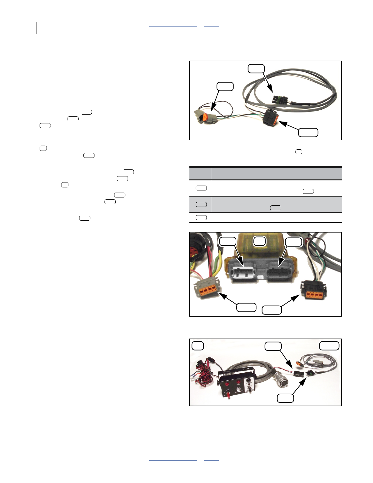
58 3PYPA Table of Contents Index Great Plains Manufacturing, Inc.
Install Module Output Harness
This harness is only used for configurations taking
ISObus steering data, or taking native tractor steering
sensor data. It is not used with the Great Plains linear
sensor.
Refer to Figure 99, and Figure 100 and Figure 101
The output harness provides a normalized PWM
steering signal to the planter, via the sensor
lead at the hitch connection. it also provides a USB
70s
port form service use.
83. From the harness set:
74
833-547C HARNESS CANBUS STEERING MODULE
select the cable with the Black 12-pin Deutsch
connector.
Plug the Black 12-pin Deutsch lead into the
Black output port receptacle of the sensor
module .
Route the PWM signal lead to the hitch. Mate it
to the sensor input lead of the switchbox
harness.
The USB lead is not used at this time. Leave
the connector capped.
71
74K
74s
74K
74K
71o
74s
70s
74u
74s
74u
Figure 99
Module Output Harness
Signal Power OUT (Black end)
Lead Function
12-pin black:
74K
data from sensor module output
3-pin weatherpak: PWM steering data to
74s
switch harness lead
3-pin wedge: USB
74u
70s
74K
31814
74
71o
74G
71
74K
Figure 100
70s
71o
31812
71i
Electronic Module Ports
70 74K
74s
Figure 101
PWN Lead to Hitch
31834
401-647Q Table of Contents Index 2012-08-08
Page 63

Great Plains Manufacturing, Inc. Table of Contents Index Tractor Steering 59
Steering Calibration
Steering System Hydraulic Bleeding
The steering system is self-purging and never requires
bleeding if operated with all four hoses correctly
connected.
Calibration
The hydraulic steering system has two calibration
modes:
a. one for caster wheel sensor calibration
b. one for tractor wheel sensor calibration.
After initial wheel calibration at delivery of the planter,
periodic re-calibration is necessary in the following
circumstances:
• Re-calibrate for use with a different tractor.
• Re-calibrate if maintenance required dismounting any
steering sensor, tire size or tractor tire size and/or
wheel arrangement has changed.
• Great Plains recommends seasonal re-calibration.
• Re-calibrate if steering software is updated.
Steering Configuration Switch
This cab-mounted switch box controls both normal and
field calibration of the hydraulic steering system. It has
2 switches, 1 button, three indicator lamps and one knob
that perform the following functions.
32
1
7
Figure 102: Calibration
Steering Control Module
Front View(top) Rear View(bottom)
5
6
4
29850
31698
Steering Control Module
Function
STEER Toggle Switch:
1
Steering System Power
LED:
2
Power / Fault
FLOAT LED:
3
Float / Caster
CALIBRATION Toggle Switch:
4
Calibration Modes
LEARN Button:
5
Calibration (Learn)
LED: Calibration Off: Normal (non-Calibration) operation
6
Rotary Switch Knob (backside) Vertical position: Normal operation - steering system active while
7
On (up): Steering enabled (casters match or float)
Off (down): Steering disabled (casters in Float)
On steady: Steering system active (casters match or float)
Blinking: Steering system fault (casters in Float)
Off: Normal operation - steering system active if STEER on
On: Casters in Float (if STEER LED is steady)
L: Caster aspect sensor (casters in Float)
C: Center-off: Calibration mode off (normal transport/field mode)
R: Tractor aspect sensor (casters in Float)
First press: Learn tight Right turn
Next press: Learn Straight ahead
Next press: Learn tight Left turn
Dim: Either Calibration mode selected
Bright Flash: Button press acknowledged
planting as well as raised
Horizontal position: Used when tractor is utilizing auto steer - steering
system floats while planting - active only when planter is raised
Switch Positions and Indications
5
2012-08-08 Table of Contents Index 401-647Q
Page 64

60 3PYPA Table of Contents Index Great Plains Manufacturing, Inc.
Wheel Sensor Calibration
The planter must be completely connected to the tractor,
and leveled, before beginning the procedure. You need a
reasonably level area large enough for completely
turning and straightening the rig.
Refer to Figure 102 and the table on page 59
1. Raise the planter. Folding is also suggested if the
test area is small, or uneven enough to cause wing
openers to touch the ground.
2. Ensure the hydraulic steering ECU is connected to
the cab switch box, and powered-up (switch ).
Caster Right Calibration
3. Put the steering in caster wheel sensor calibration
mode, by setting Calibration switch to the
4
“CASTER” position.
Note: Do not move the Calibration toggle switch from the
“CASTER” position until step 10, or the new caster
calibration is ignored.
4. Make a complete forward right circle, as tight as the
rig permits, with all wheels in a hard right turn.
Stop.
5. Press and hold the “learn” button on the switch
box, until the LEARN indicator flashes. Normally.
5
6
the illumination response takes less than a second.
Steering Mismatch Risk:
Do not press the LEARN button more than once for each
orientation (right, straight, left). If pressed more than once,
invalid steering data is stored. You must re-start the sequence
(see “Errors and Re-Tries”).
Caster Straight Calibration
6. Drive straight forward until the entire rig is running in
a straight line. Stop, with all wheels straight ahead.
7. Press and hold the “learn” button on the switch
box, until the LEARN indicator flashes.
5
6
Caster Left Calibration
8. Make a complete forward left hand circle, as tight as
the rig permits, with all wheels in a hard left turn.
Stop.
9. Press and hold the “learn” button on the switch
box, until the LEARN indicator flashes.
5
6
10. Complete the caster wheel sensor calibration mode,
by setting Calibration switch to “OFF”.
4
1
Wheel Tractors and Alternate Method for Tracked
Tractors
Tractor Right Calibration
11. Put the steering in tractor wheel sensor calibration
mode, by setting Calibration switch to the
4
“TRACTOR” position.
Note: Do not move the Calibration toggle switch from the
“TRACTOR” position until step 18, or the new
tractor calibration is ignored.
12. Make a complete forward right turn, as tight as the
rig permits, with all wheels in a hard right turn.
Stop.
13. Press and hold the “learn” button on the switch
box, until the LEARN indicator flashes.
5
6
Steering Mismatch Risk:
Do not press the LEARN button more than once for each
orientation (right, straight, left). If pressed more than once,
invalid steering data is stored. You must re-start the sequence
(see “Errors and Re-Tries”).
Tractor Straight Calibration
14. Drive straight forward until the entire rig is running in
a straight line. Stop, with all wheels straight ahead.
15. Press and hold the “learn” button on the switch
box, until the LEARN indicator flashes.
5
6
Tractor Left Calibration
16. Make a complete forward left turn, as tight as the rig
permits, with all wheels in a hard left turn.
Stop.
17. Press and hold the “learn” button on the switch
box, until the LEARN indicator flashes.
5
6
18. Complete the tractor wheel sensor calibration mode,
by setting Calibration switch to “OFF”.
4
Errors and Re-Tries
If you are unable to complete a sequence, set the
Calibration switch to “OFF”, and restart the calibration
4
sequence from the beginning (step 3 for caster or
step 11 for tractor). Do not attempt to start from where
you left off.
If you need to re-try a sequence (for example, you run
out of room to complete a circle or straight run), set the
Calibration switch to “OFF”, reposition the rig and
4
begin again.
It is not necessary to re-calibrate caster steering, if only
the tractor steering needs to be re-done.
401-647Q Table of Contents Index 2012-08-08
Page 65

Great Plains Manufacturing, Inc. Table of Contents Index Tractor Steering 61
Track Tractor Preferred Method of Tractor Steering Sensor Calibration
19. Turn the Ignition Switch to the ON position. DO NOT
START the ENGINE.
20. Put the Steer Toggle switch to the ON position. The
power light on the steering switch box and the LED’s
on the electronic steering module should all be
illuminated.
21. Put the steering in the tractor sensor calibration
mode by setting Calibration switch to the
4
TRACTOR position.
Note: Do not move the Calibration toggle switch from the
TRACTOR position until step 28 or the new tractor
calibration is ignored.
22. Turn the steering wheel all the way to the right and
hold in this position to simulate a hard right hand
23. Press and hold the LEARN button on the switch
box until the LEARN indicator flashes.
5
6
24. Release the steering wheel. It should return to the
center position.
25. Press and hold the LEARN button on the switch
box until the LEARN indicator flashes.
5
6
26. Turn the steering wheel all the way to the left and
hold in this position to simulate a hard left hand turn.
27. Press and hold the LEARN button on the switch
box until the LEARN indicator flashes.
5
6
28. Complete the tractor sensor calibration mode by
setting Calibration switch to OFF. Only at this point
4
are the new calibration values accepted by the
system.
turn.
Steering Troubleshooting
See Operator manual for general planter
troubleshooting.
Always check any steering switch box flash error codes
before searching for other causes of problems.
See Operator manual for switch box operations.
Then see “Steering Flash Error Codes” on page 63.
The chart below presumes that the switch box is
reporting normal operation.
Steering Troubleshooting (other than flash error codes)
Problem Cause Solution
Any
Casters turn
abruptly at
system
power-up
No steering
Most that cannot be corrected in
place
This is normal if the tractor steering
at hitching is substantially different
from that at unhitching
Hydraulic hoses not connected Correctly connect steering hydraulics.
Steering sense line not connected Correctly connect steering hydraulics.
Power-Beyond hoses reversed Correctly connect steering hydraulics.
Power-Beyond sense line
disconnected
No pressure at Power-Beyond port Unless there is a valve for the port, that is shut off, this is a
Steering manifold valve malfunction Have dealer check solenoid coils and plungers.
Tractor sensor failed (other than
open circuit or short to ground)
Caster sensor failed (other than
open circuit or short to ground)
If the planter must be moved for repairs, make ONLY
careful forward moves unless caster pins are removed (see
Operator manual).
Keep all persons away from casters at power-up. Allow no
one on the walkboard at power-up.
Note: To minimize caster movement at power-up, unhitch
and re-hitch with the tractor steering in a consistent
orientation, usually straight ahead.
Correctly connect steering hydraulics.
tractor system malfunction
Check for obvious mechanical problems (such as loose
fasteners). Replace failed or damaged sensor.
Check for obvious mechanical problems (such as loose
fasteners). Replace failed or damaged sensor.
2012-08-08 Table of Contents Index 401-647Q
Page 66

62 3PYPA Table of Contents Index Great Plains Manufacturing, Inc.
Steering Troubleshooting (other than flash error codes)
Problem Cause Solution
ECU does not
power up
(no lights on
switch box)
Steering
doesn’t match
tractor
No caster
float in
transport
Steering
reversed
Fuse blown Check fuse, located at + battery terminal. If blown, check
for underlying problem before using system:
1. Set STEER switch off on console.
2. Disconnect harness to ECU
(ECU has standby power, even with console off).
3. Replace fuse.
4. Switch on console - check fuse.
If OK, switch off console and continue.
5. Connect ECU harness. Check fuse. If OK, continue.
6. Switch on console and check fuse.
Power input disconnected or
damaged.
Low battery voltage Check tractor voltage. Must be between 10 and 16Vdc.
Calibration needed Perform a steering calibration (page 59). If calibration does
No radar signal (seen by ECU as
0 mph)
Disengage speed not set to proper
value in ECU setup
Sensor installed on incorrect tractor
side or incorrect location on axle
ST1 and ST2 connections reversed
at manifold valve
Hoses to steering cylinders reversed
at left cylinder
Harness connections reversed at
valve coils
Check voltage at 70-pin ECU plug, with console on:
Pins 1 and 2, then Pins 2 and 3
not solve the problem, check for damaged sensor.
Check radar Y-cable connection and radar function
Contact Great Plains support. If the ECU firmware was
recently updated, there may be other incorrect settings.
Re-install sensor at location specified in Pre-Delivery
manual 401-647Q.
Check entire hydraulic system against diagrams in Parts
manual. Correct connections as necessary. If the
mis-connection was not the result of local maintenance,
report problem to dealer or Great Plains.
Check entire hydraulic system against diagrams in Parts
manual. Correct connections as necessary. If the
mis-connection was not the result of local maintenance,
report problem to dealer or Great Plains.
Swap connections at ST1 and ST2. If the mis-connection
was not the result of local maintenance, report problem to
dealer or Great Plains.
401-647Q Table of Contents Index 2012-08-08
Page 67

Great Plains Manufacturing, Inc. Table of Contents Index Tractor Steering 63
Steering Flash Error Codes
Failure and errors detected by the self-diagnostics in the
steering ECU are presented to the operator as a series
of flashes of the Power LED.
There are 2 to 12 flashes, interrupted by a short pause.
Multiple errors are flashed in rotation, with a long pause
between each error code. A maximum of five error states
are reported in any single rotation.
Any of these errors causes the ECU to default the
hydraulic steering to Float.
Code Diagnostic Corrective Action
1 - 1 Float valve HS short to battery
1 - 1 Float valve LS short to battery
1 - 2 Float valve HS short to ground
1 - 2 Float valve LS short to ground
1 - 3 Float valve open circuit
2 - 1 ST1 valve HS short to battery
2 - 1 ST1 valve LS short to battery
2 - 2 ST1 valve HS short to ground
2 - 2 ST1 valve LS short to ground
2 - 3 ST1 valve open circuit
3 - 1 ST2 valve HS short to battery
3 - 1 ST2 valve LS short to battery
3 - 2 ST2 valve HS short to ground
3 - 2 ST2 valve LS short to ground
3 - 3 ST2 valve open circuit
Check float valve coil and cable to ECU.
ECU is detecting an unexpected voltage in the circuit.
Check float valve coil and cable to ECU.
ECU is detecting a short to ground.
Check float valve coil and cable to ECU.
ECU is failing to detect presence of coil - no circuit continuity.
Check ST-1 valve coil and cable to ECU.
ECU is detecting an unexpected voltage in the circuit.
Check ST-1 valve coil and cable to ECU.
ECU is detecting a short to ground.
Check ST-1 valve coil and cable to ECU.
ECU is failing to detect presence of coil - no circuit continuity.
Check ST-2 valve coil and cable to ECU.
ECU is detecting an unexpected voltage in the circuit.
Check ST-2 valve coil and cable to ECU.
ECU is detecting a short to ground.
Check ST-2 valve coil and cable to ECU.
ECU is failing to detect presence of coil - no circuit continuity.
Check tractor wheel sensor for:
5 - 1 Tractor sensor short to ground
A. travel limits of sensor.
B. cable to ECU
C. function of sensor
5 - 2 Tractor sensor open circuit ECU not detecting tractor sensor. Use same steps as for 5 - 1.
6 - 1 Caster sensor short to ground Check caster wheel sensor, using same steps as for 5 - 1.
6 - 2 Caster sensor open circuit ECU not detecting caster sensor. Use same steps as for 5 - 1.
8 - 1 ECU low voltage
Check tractor voltage above 10Vdc.
Check connections to ECU. Check harnesses and switchbox connections.
Certain Machine Damage:
Do not back up if ANY of these errors occurs.
Steering is disabled.
The wheels cannot fully caster and machine damage will result. If the
problem cannot be corrected in the field, drive forward to remove the
planter from the field.
29894
2012-08-08 Table of Contents Index 401-647Q
Page 68

64 3PYPA Table of Contents Index Great Plains Manufacturing, Inc.
Appendix A - Reference Information
Specifications and Capacities, 1 of 2
Model 3PYPA -1236 -1238 -1240 -1630 -24TR36
Row Count
Row Spacing
Working Width
Span (width between end rows)
Swath (Channel Width)
Seed Capacity
Transport Width
Working Length
Transport Length
Working Height
Transport Height, no Markers
Transport Height, with Markers
Transport Clearance
Minimum Tractor HP Requirement¹
Hitch
Hydraulic Circuits Required
Weight (empty, base)²
Weight (maximum, full)³
Transport Tire Size
Hydraulic Drive Tire
Ground Drive Tire
Opener Down Pressure
Opener Travel (Up - Down)
Opener Depth Range
1. Power requirements vary significantly with conditions and practices.
2. No seed container, markers, coulters or row cleaners
3. Weight can vary by thousands of pounds depending on options installed.
12 12 12 16 24 (12 twin)
36 in 38 in 40 in 30 in 36 in
40ft 0in
396 in 418 in 440 in 450 in 396 in
432 in 456 in 480 in 480 in 432 in
Optional 82bu hopper or PROBOX® 50 unit bulk seed box
25ft 2in 25ft 2in 25ft 2in 25ft 2in 25ft 2in
16ft 10in
16ft 10in
12ft 4in
12ft 6in
12ft 8in
14.00
220 - 240 hp 220 - 250 hp 220 - 250 hp 230 - 260 hp 260 - 300 hp
3-Point semi-mounted
Closed-Center, 5 Remotes (1 Power-Beyond), 2250 psi, 23 gal/min
14500 lbs 14500 lbs 14500 lbs 15300 lbs 17000 lbs
22700 lbs 22700 lbs 22700 lbs 23800 lbs 25900 lbs
16.51-16.1 FI 14 Ply Implement
9.5L x 15 6 Ply Rib Implement
7.60-145 6 Ply Lug
235 to 475 lbs
10 in
0 to 3.5 in
401-647Q Table of Contents Index 2012-08-08
Page 69

Great Plains Manufacturing, Inc. Table of Contents Index Appendix A - Reference Information 65
Specifications and Capacities, 2 of 2
Model 3PYPA -24TR38 -24TR40 -3115 -32TR30
Row Count
Row Spacing
Working Width
Span (width between end rows)
Swath (Channel Width)
Seed Capacity
Transport Width
Working Length
Transport Length
Working Height
Transport Height, no Markers
Transport Height, with Markers
Transport Clearance
Minimum Tractor HP Requirement¹
Hitch
Hydraulic Circuits Required
Weight (empty, base)²
Weight (maximum, full)³
Transport Tire Size
Hydraulic Drive Tire
Ground Drive Tire
Opener Down Pressure
Opener Travel (Up - Down)
Opener Depth Range
1. Power requirements vary significantly with conditions and practices.
2. No seed container, markers, coulters or row cleaners
3. Weight can vary by thousands of pounds depending on options installed.
24 (12 twin) 24 (12 twin) 31 32 (16 twin)
38 in 40 in 15 in 30 in
40ft 0in
418 in 440 in 450 in 458 in
456 in 480 in 465 in 480 in
Optional 82bu hopper or PROBOX® 50 unit bulk seed box
25ft 2in 25ft 2in 25ft 2in 24ft 6in
16ft 10in
16ft 10in
12ft 4in
12ft 6in
12ft 8in
14.00
260 - 300 hp 260 - 300 hp 290 - 320 hp 290 - 330 hp
3-Point semi-mounted
Closed-Center, 5 Remotes (1 Power-Beyond), 2250 psi, 23 gal/min
17000 lbs 17000 lbs 18400 lbs 18700 lbs
25900 lbs 25900 lbs 27800 lbs 28100 lbs
16.51-16.1 FI 14 Ply Implement
9.5L x 15 6 Ply Rib Implement
7.60-145 6 Ply Lug
235 to 475 lbs
10 in
0 to 3.5 in
Tire Inflation Chart Tire Warranty Information
Wheel Tire Size Inflation
Transport/
Caster
Ground
Drv.Gauge
Wheel
Hyd. Drive
Gauge
Wheel
2012-08-08 Table of Contents Index 401-647Q
16.51-16.1 FI
14-Ply Implement
7.60-145 6-Ply
Lug
9.5L x 15 6-Ply
Rib Implement
60 psi
(414 kPa)
32 psi
(221 kPa)
35 psi
(241 kPa)
All tires are warranted by the original manufacturer of the tire.
Tire warranty information is found in the brochures included with
your Operator’s and Parts Manuals or online at the
manufacturer’s web sites listed below. For assistance or
information, contact your nearest Authorized Farm Tire Retailer.
ManufacturerWeb site
Firestonewww.firestoneag.com
Gleasonwww.gleasonwheel.com
Titanwww.titan-intl.com
Page 70

66 3PYPA Table of Contents Index Great Plains Manufacturing, Inc.
Torque Values Chart
Bolt
Size
in-tpi
1
⁄4-20
1
⁄4-28
5
⁄16-18
5
⁄16-24
3
⁄8-16
3
⁄8-24
7
⁄16-14
7
⁄16-20
1
⁄2-13
1
⁄2-20
9
⁄16-12
9
⁄16-18
5
⁄8-11
5
⁄8-18
3
⁄4-10
3
⁄4-16
7
⁄8-9
7
⁄8-14
1-8
1-12
1
⁄8-7
1
1
1
⁄8-12
1
1
⁄4-7
1
1
⁄4-12
3
⁄8-6
1
3
1
⁄8-12
1
1
⁄2-6
1
1
⁄2-12
Bolt Head Identification
Grade 2 Grade 5 Grade 8 Class 5.8 Class 8.8 Class 10.9
a
b
d
N-m
ft-lb
7.4 11 16
8.5 13 18
15 24 33
17 26 37
27 42 59
31 47 67
43 67 95
49 75 105
66 105 145
75 115 165
95 150 210
105 165 235
130 205 285
150 230 325
235 360 510
260 405 570
225 585 820
250 640 905
340 875 1230
370 955 1350
480 1080 1750
540 1210 1960
680 1520 2460
750 1680 2730
890 1990 3230
1010 2270 3680
1180 2640 4290
1330 2970 4820
N-m N-m
5.6 8 12
61014 5 811
11 17 25 12 19 27
13 19 27 13 21 29
20 31 44 24 39 53
22 35 49 29 45 62
32 49 70 42 67 93
36 55 78 44 70 97
49 76 105 66 77 105
55 85 120 68 105 150
70 110 155 73 115 160
79 120 170 105 165 230
97 150 210 115 180 245
110 170 240 145 230 300
170 265 375 165 260 355
190 295 420 205 325 450
165 430 605 230 480 665
185 475 670 355 560 780
250 645 910 390 610 845
275 705 995 705 1120 1550
355 795 1290 785 1240 1710
395 890 1440 1270 1950 2700
500 1120 1820 1380 2190 3220
555 1240 2010
655 1470 2380
745 1670 2710
870 1950 3160
980 2190 3560
Bolt Head Identification
Bolt
Size
ft-lb ft-lb ft-lb ft-lb ft-lb
mm x pitch
M 5 X 0.8
M 6 X 1
M 8 X 1.25
M 8 X 1
M10 X 1.5
M10 X 0.75
M12 X 1.75
M12 X 1.5
M12 X 1
M14 X 2
M14 X 1.5
M16 X 2
M16 X 1.5
M18 X 2.5
M18 X 1.5
M20 X 2.5
M20 X 1.5
M24 X 3
M24 X 2
M30 X 3.5
M30 X 2
M36 X 3.5
M36 X 2
a. in-tpi = nominal thread diameter in inches-threads per inch
b. N· m = newton-meters
c. mm x pitch = nominal thread diameter in mm x thread pitch
d. ft-lb = foot pounds
c
5.8 8.8 10.9
N-m N-m N-m
357
71115
17 26 36
18 28 39
33 52 72
39 61 85
58 91 125
60 95 130
90 105 145
92 145 200
99 155 215
145 225 315
155 240 335
195 310 405
220 350 485
280 440 610
310 650 900
480 760 1050
525 830 1150
960 1510 2100
1060 1680 2320
1730 2650 3660
1880 2960 4100
946
Torque tolerance + 0%, -15% of torquing values. Unless otherwise specified use torque values listed above.
401-647Q Table of Contents Index 2012-08-08
25199m
25199
Page 71

Great Plains Manufacturing, Inc. Table of Contents Index Appendix A - Reference Information 67
Hydraulic Diagrams
Lift Hydraulics (Wing Lock)
U
R
B
F
L
D
29112
2012-08-08 Table of Contents Index 401-647Q
Page 72

68 3PYPA Table of Contents Index Great Plains Manufacturing, Inc.
Lift Hydraulics (Wing Flex)
U
R
B
F
L
D
29113
401-647Q Table of Contents Index 2012-08-08
Page 73
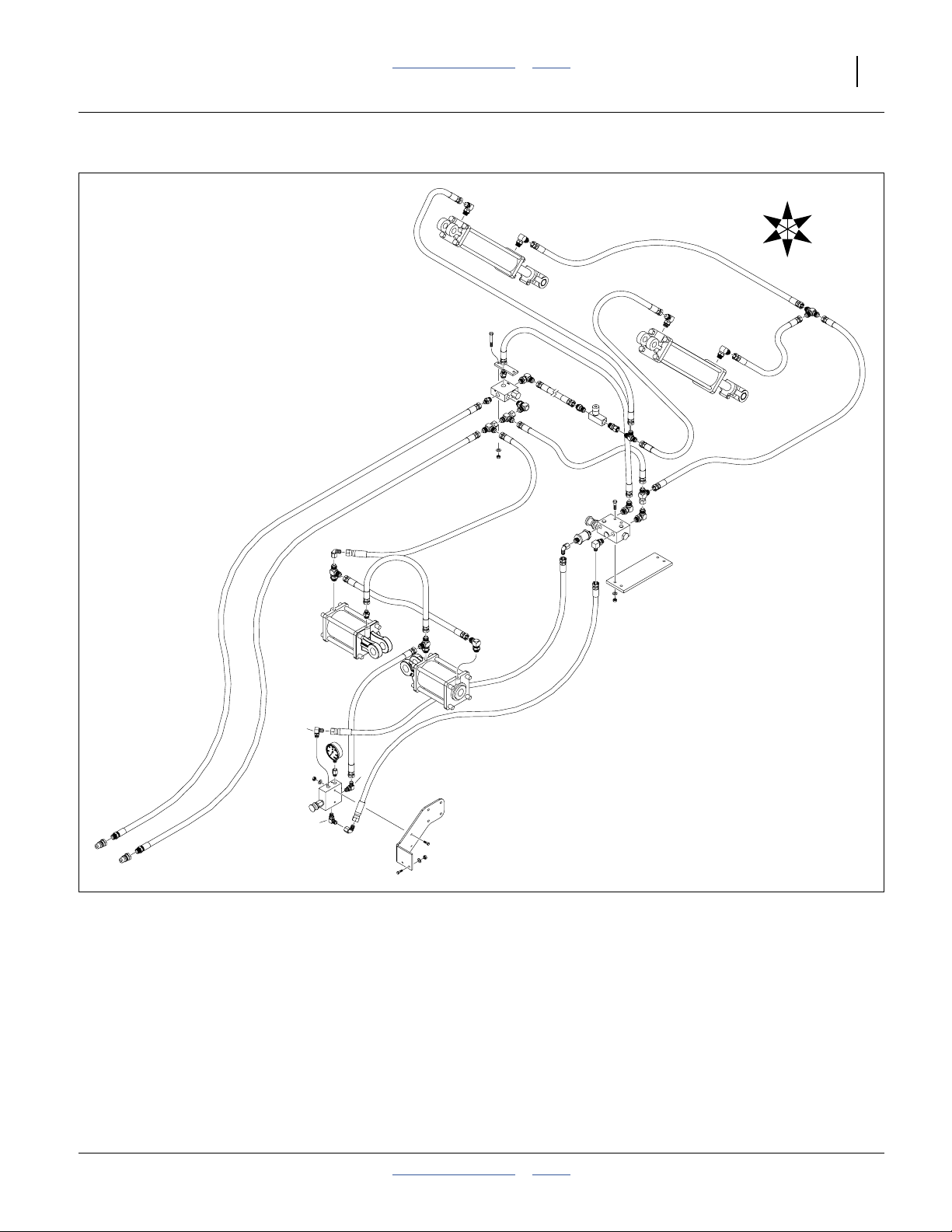
Great Plains Manufacturing, Inc. Table of Contents Index Appendix A - Reference Information 69
Lift Hydraulics (Weight Transfer)
U
R
B
F
L
D
27484
2012-08-08 Table of Contents Index 401-647Q
Page 74
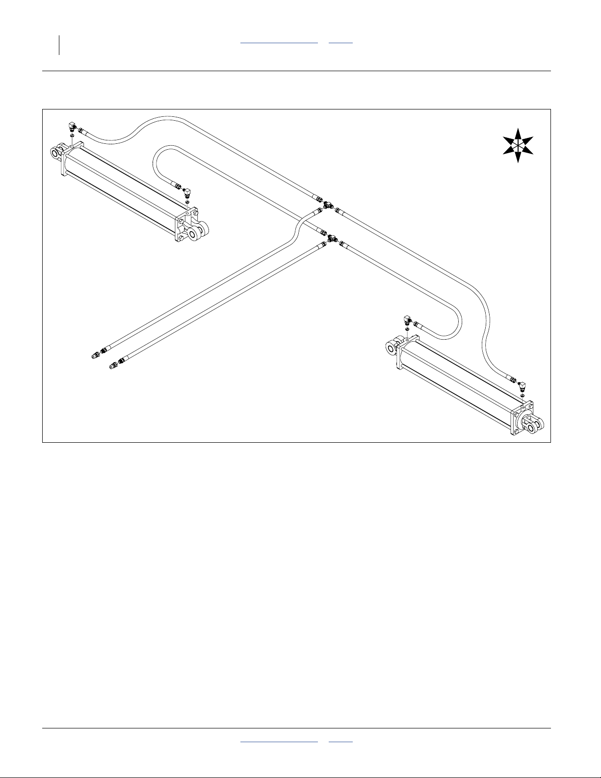
70 3PYPA Table of Contents Index Great Plains Manufacturing, Inc.
Wing Fold Hydraulics (no Markers)
U
R
B
25195
F
L
D
401-647Q Table of Contents Index 2012-08-08
Page 75
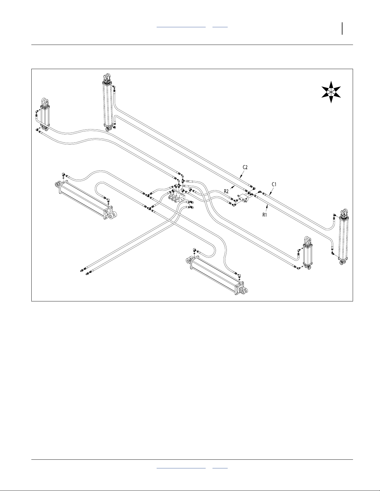
Great Plains Manufacturing, Inc. Table of Contents Index Appendix A - Reference Information 71
Wing Fold and Marker Hydraulics
U
R
B
F
L
D
25062
2012-08-08 Table of Contents Index 401-647Q
Page 76

72 3PYPA Table of Contents Index Great Plains Manufacturing, Inc.
Fan and Steering Hydraulics
U
R
B
F
L
D
31472
401-647Q Table of Contents Index 2012-08-08
Page 77
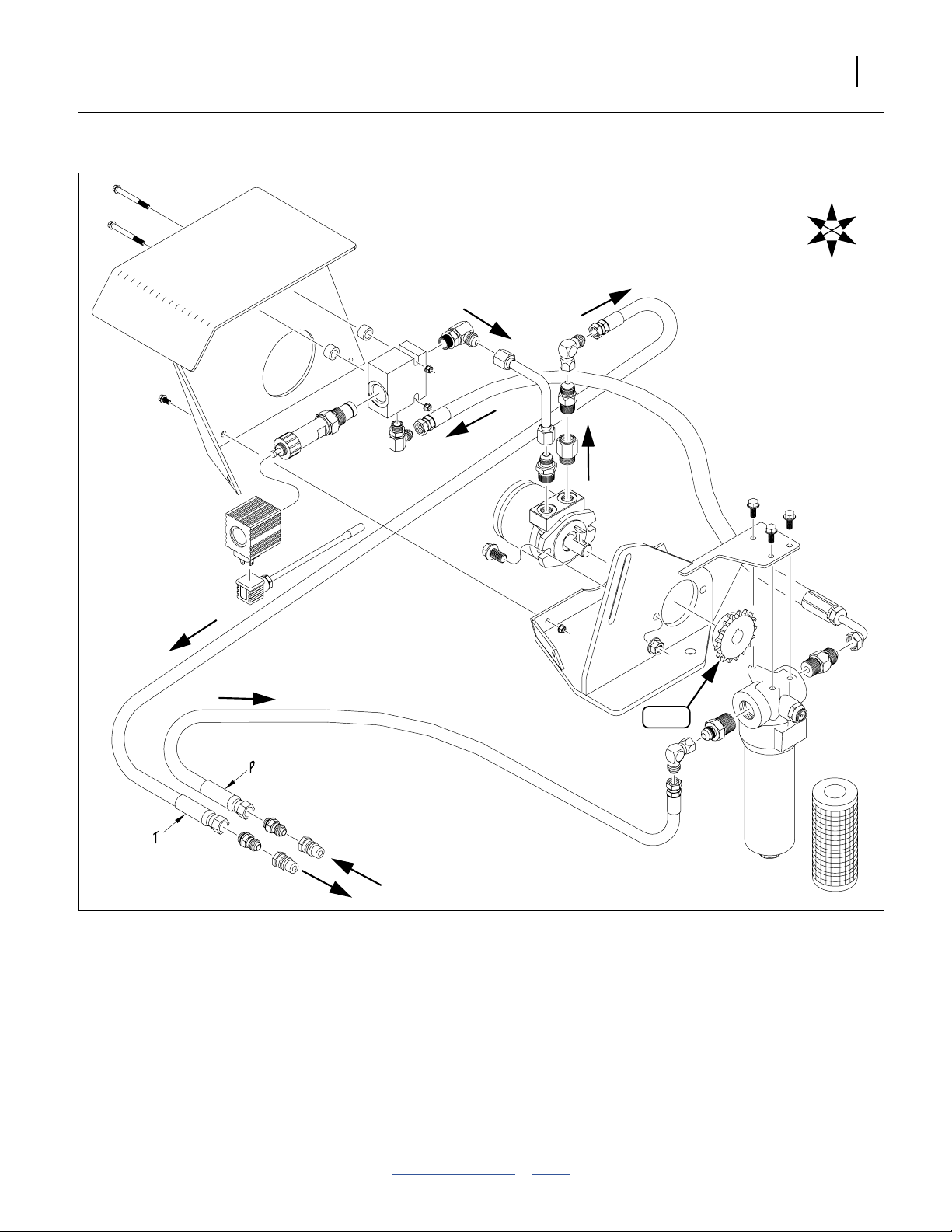
Great Plains Manufacturing, Inc. Table of Contents Index Appendix A - Reference Information 73
Hydraulic Drive (Option)
U
R
B
F
L
D
17T
25120
2012-08-08 Table of Contents Index 401-647Q
Page 78
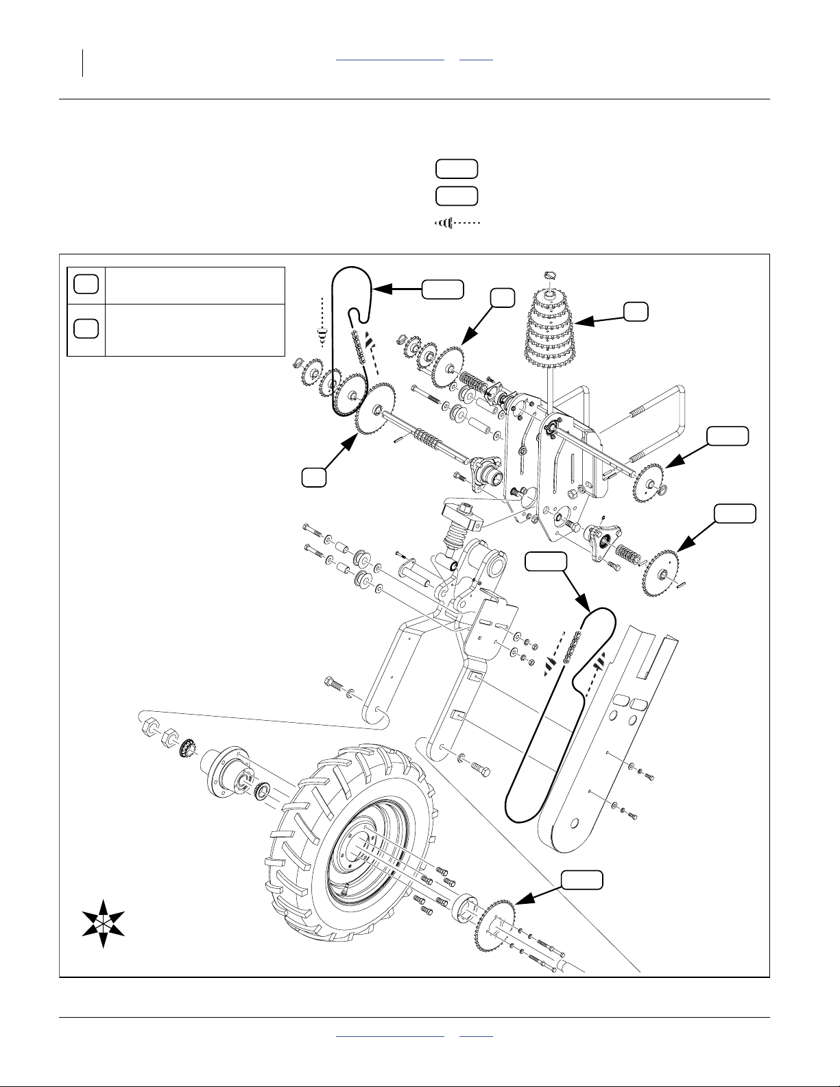
74 3PYPA Table of Contents Index Great Plains Manufacturing, Inc.
Chain Routing
Gauge Wheel (Ground Drive) Chains
Range Sprockets:
A
15T, 18T, 19T, 20T, 30T, 38T
Transmission Sprockets:
17T, 19T, 2@23T, 24T, 25T,
B
26T, 27T, 28T
A
Legend:
34T
56P
107
Sprocket or idler Tooth count
Chain Pitch count
Direction of chain in motion
A
B
28T
34T
R
F
U
D
120
38T
B
L
25061
401-647Q Table of Contents Index 2012-08-08
Page 79
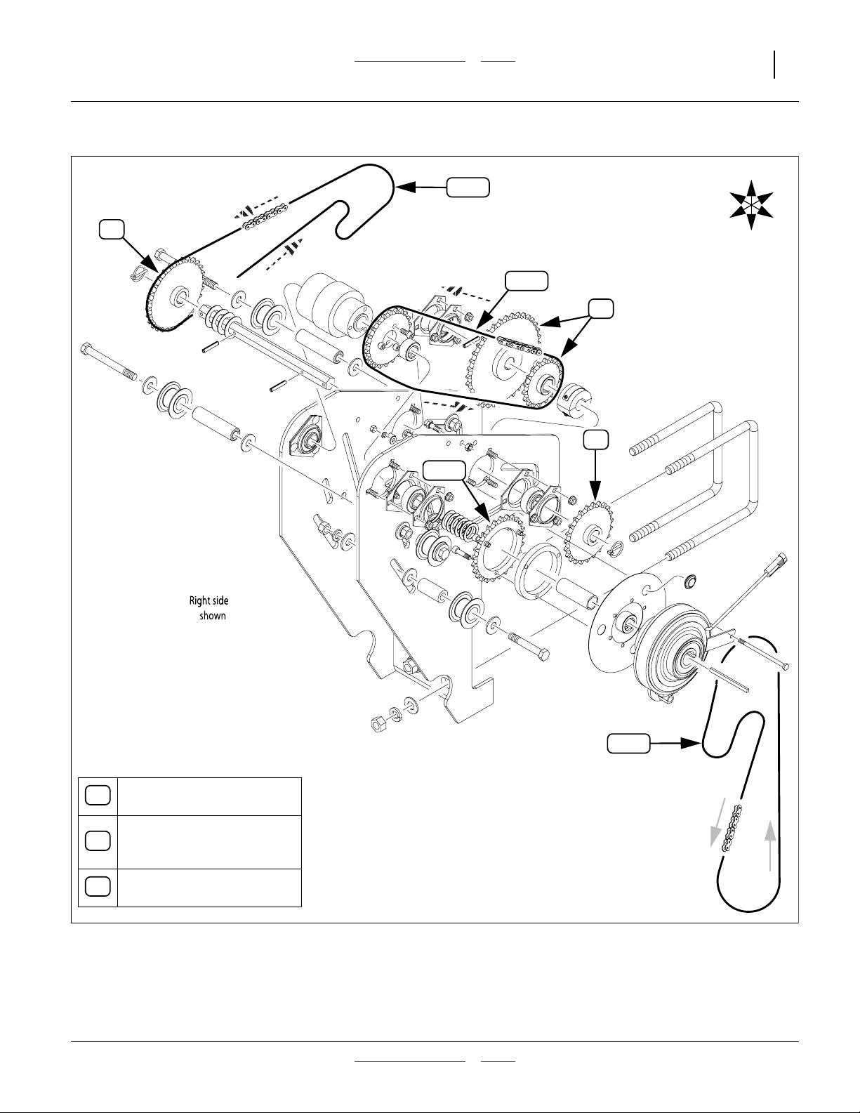
Great Plains Manufacturing, Inc. Table of Contents Index Appendix A - Reference Information 75
Transmission (Ground Drive) Chains
U
82P
R
B
B
25T
70P
A
C
F
L
D
105
Range Sprockets:
A
15T, 18T, 19T, 20T, 30T, 38T
Transmission Sprockets:
17T, 19T, 2@23T, 24T, 25T,
B
26T, 27T, 28T
Upper Drive Sprockets:
C
18T or 36T, captive
2012-08-08 Table of Contents Index 401-647Q
25073
Page 80

76 3PYPA Table of Contents Index Great Plains Manufacturing, Inc.
Ground Drive Chain
U
R
B
25T
109
F
L
D
25229
401-647Q Table of Contents Index 2012-08-08
Left side
shown
Page 81

Great Plains Manufacturing, Inc. Table of Contents Index Appendix A - Reference Information 77
Hydraulic Drive Chain (Option)
25T
30T
63P
23T
17T
25T
R
F
U
B
L
D
78P
109
30T
30T
30T
105
25060
2012-08-08 Table of Contents Index 401-647Q
Page 82

78 3PYPA Table of Contents Index Great Plains Manufacturing, Inc.
25AP Final Meter Drive
0
1
Legend:
34T
56P
Sprocket or idler Tooth count
Chain Pitch count
Direction of chain in motion
19T
12T
94P
2
19T
29619
25P: Meter Drive (Front type)
Note: No idlers on mount.
0
1
top chain passes over single idler on shank
2
be sure to reconnect idler spring
3
4
19T
4
12T
2
120
29620
2
148
3
12T
29621
25P: Meter Drive (Mid type)
Note: be sure to reconnect idler spring
401-647Q Table of Contents Index 2012-08-08
2
3
top chain passes between 2 idlers at mount
4
top chain passes between 2 idlers at shank
Note: be sure to reconnect idler spring
25P: Meter Drive (Rear type)
2
3
top chain passes between 2 idlers at mount
4
top chain passes between 2 idlers at shank
Page 83

Great Plains Manufacturing, Inc. Table of Contents Index 79
Index
A
address, Great Plains .......................... 8
air box ................................................ 28
air box pads........................................ 28
Air-Pro™ .............................................. 5
arm locking bar .................................. 21
arm, side depth .................................. 37
articulated tractors ............................... 5
assembly location................................. 9
B
battery ................................................ 41
bleeding
steering ........................................ 59
BRKT SENSOR ................................. 42
bushel ................................................ 38
C
cab, tractor .................................. 40,42
CALIBRATION ................................... 59
calibration
steering ........................................ 59
CANbus .............................................. 53
capacities ........................................... 64
capacity, hopper ................................. 38
Case ............................................ 54
Case IH ....................................... 42,44
CASTER ............................................ 60
caster ................................................. 23
caster assemblies ................................ 7
caster float ......................................... 39
caster movement................................ 61
CAUTION, defined ............................... 1
center of gravity.................................. 11
chain routing ...................................... 74
chains ................................................. 16
gauge wheel ................................. 74
ground drive ................................. 76
hydraulic drive .............................. 77
meter drive ................................... 78
transmission ................................. 75
clamp, routing..................................... 34
clothing ................................................. 2
compatible tractor................................. 5
console
seed monitor ................................ 40
contact Great Plains ............................. 8
conventional till..................................... 5
covered models .................................... 5
cradle ................................................. 34
crane .................................................... 1
crate ..................................................... 8
cross-bolt ........................................... 24
cylinder, steering ................................ 27
,55
D
DANGER, defined ................................ 1
Deere ............................... 5, 42,46,48
definitions ............................................. 6
delivery, final ........................................ 6
DICKEY-john® .............................. 6, 40
directions ............................................. 6
E
eccentric adjuster .............................. 36
ECU ................................................... 63
ECU fuse ........................................... 62
email, Great Plains .............................. 8
emergency moves ............................. 39
error code, steering ........................... 63
extensions, rubber ............................. 35
F
final delivery ......................................... 6
fire ........................................................ 1
flanges ............................................... 22
flash error code .................................. 63
FLOAT ................................................ 59
fork lift ................................................ 11
four lift ................................................ 14
fuse, ECU .......................................... 62
G
gauge wheel, row............................... 37
gauge wheel, wing ............................. 37
grease zerk ........................................ 18
H
headphones ......................................... 2
hearing ................................................. 2
high pressure fluids ............................. 2
hoist ..................................................... 9
hoist points ........................................ 10
hopper ............................. 7,26, 37,38
hopper level sensor ............................. 6
HOPPER 2 ........................................ 37
hose ................................................... 33
hose rack .....................................31, 32
hoses, seed ....................................... 33
hose, air box inlet............................... 34
hose, steering .................................... 27
hydraulic diagram .............................. 67
hydraulic safety .................................... 2
hydraulics
fan ................................................ 72
lift (down pressure) ...................... 69
lift (wing flex) ................................ 68
lift (wing lock) ............................... 67
markers ........................................ 71
meter drive ................................... 73
steering ........................................ 72
wing fold ....................................... 70
wing fold & markers ..................... 71
I
ILS ...............................................42,48
ILS (Independent Live Suspension)... 42
Independent Live Suspension ............. 5
inflation .............................................. 65
inlet hose ........................................... 34
installation
hopper sensor .............................. 38
monitor console............................ 40
IntelliAg® .............................................. 6
intended usage ..................................... 5
inventory ............................................... 7
ISO 11786 ..........................................53
ISObus ............................................... 53
J
John Deere .......................5, 42, 46, 48
John Deere® ........................ 54,56, 57
L
leaks ..................................................... 2
LEARN ........................................ 59,60
left-hand, defined ................................. 6
lift assist cylinders .............................. 39
lift assist wheels ................................... 7
lift points .............................................11
lift-assist ............................................. 23
lifters ................................................ 1,9
light no-till .............................................5
lighting ................................................ 28
lights ..................................................... 3
location, assembly ................................9
lock-down pins....................................10
lug nut.................................................24
M
Magnum ........................................ 5,42
Magnum™ .......................................... 44
main frame ........................................... 7
maintenance safety ..............................3
manuals ................................................ 6
medical assistance ...............................2
meter drive chain ................................ 78
minimum-till ..........................................5
miscellaneous crate............................15
MX .......................................... 5,42, 44
N
New Holland ................................54,55
Note, defined ........................................ 6
NOTICE, defined ..................................6
no-till ..................................................... 5
no-till, light ............................................5
O
orientation rose .................................... 6
P
pads, air box ....................................... 28
parallel arms ....................................... 21
parking stands .................................... 20
pavement..............................................9
phone number, GP ............................... 8
pin, lift-assist.......................................22
pin, parallel arm ..................................21
Planter/Drill Control ..............................6
ports ............................................ 31,32
press wheel ................................. 20,36
protective equipment ............................2
P01-P16 ............................................. 33
R
rack, hose ........................................... 29
2012-08-08 Table of Contents 401-647Q
Page 84

80 3PYPA Table of Contents Index Great Plains Manufacturing, Inc.
RFS ............................................. 42,46
RFS (rigid front suspension) .............. 42
right-hand, defined ............................... 6
rigid front suspension ......................... 42
rose, orientation ................................... 6
routing clamp ..................................... 34
row unit .............................................. 38
R-Series ............................................. 53
rubber extensions .............................. 35
S
safety information................................. 1
safety symbol ....................................... 1
seed box frame .................................. 22
seed box sensor................................. 28
seed frame ......................................... 15
seed frame stands ............................. 20
seed hoses......................................... 29
seed monitor console ......................... 40
seed support structure .................. 7,22
seed tube ........................................... 29
semi-mounted implement..................... 5
sensor ...................................43, 44,46
sensor, hopper level ............................. 6
sensor, seed box ................................ 28
shipping stand ............................. 20,23
shutdown.............................................. 4
side gauge wheel ............................... 37
single-lift ............................................. 12
space required ..................................... 9
specifications ..................................... 64
spindle................................................ 24
splitter ......................................... 31, 32
stands, parking................................... 20
stand, shipping ................................... 20
STEER ............................................... 59
steering .............................................. 41
steering calibration ............................. 59
steering cylinder ................................. 27
steering error code ............................. 63
steering hose ..................................... 27
steering switch ................................... 50
step .................................................... 35
storage ................................................. 4
ST1 .................................................... 62
ST2 .................................................... 62
support ................................................. 8
switch box ................................... 59,60
switch panel ....................................... 40
switchbox ........................................... 41
symbol, safety ...................................... 1
T
tables
document family ............................. 6
models covered .............................. 5
specifications(1) ........................... 64
specifications(2) ........................... 65
steering flash errors ..................... 63
steering switch ............................. 59
steering troubleshooting ............... 61
supported tractors .......................... 5
tire inflation ................................... 65
torque values................................ 66
tractor steering parts .................... 42
12 port hoses ................................31
16 port hoses ................................32
tail light ...............................................28
team......................................................9
three lift ...............................................13
thrust washer ......................................24
tie-down straps ...................................16
tire inflation .........................................65
tire pressure........................................26
tires .......................................................2
torque
fastener .........................................66
tracked tractors .....................................5
TRACTOR ..........................................60
tractor cab...........................................40
tractor compatibility...............................5
transport speed ....................................3
troubleshooting ...................................61
steering .........................................61
tubes ............................................31
tube, wing ...........................................33
two lift .................................................12
T01-T12 ..............................................33
,32
U
U-bolt, hopper .....................................26
unload .................................................15
URLs, tires ..........................................65
USB ....................................................58
User Level 1..........................................6
User Level 2..........................................6
V
virtual terminal ....................................40
W
walkboard ...................... 22,29, 35,37
WARNING, defined...............................1
warranty ..............................................65
washer, thrust .....................................24
welding .................................................3
wing tube ............................................33
wings ..................................................10
Y
YP4025A ..............................................5
Y-tube .................................................33
Z
zerk .....................................................18
Numerics
11001-1126, manual...................... 6, 38
110011501, manual ..............................6
110011508, manual ..............................6
110011528, manual ..............................6
110011529, manual ..............................6
110011530, manual ..............................6
110011531, manual ..............................6
120-306D, tube ...................................30
13 mph..................................................3
16.51-16.1 ..........................................65
20 mph..................................................3
22 kph ...................................................3
3PYPA-1236 .................................... 5, 6
3PYPA-1238 .................................... 5, 6
3PYPA-1240 .................................... 5, 6
3PYPA-1630 .................................... 5
3PYPA-24TR36 ............................... 5, 6
3PYPA-24TR38 ............................... 5
3PYPA-24TR40 ............................... 5
3PYPA-3115 ..............................5,6, 37
3PYPA-32TR30 ............................... 5, 6
3PYP-1236 ......................................... 31
3PYP-1238 ......................................... 31
3PYP-1240 ......................................... 31
3PYP16 ................................................5
3PYP-1630 ......................................... 32
3PYP-2320 ......................................... 31
3PYP-24TR36 ....................................31
3PYP-24TR38 ....................................31
3PYP-24TR40 ....................................31
3PYP-3115 ......................................... 32
3PYP-32TR30 ....................................32
315-032, harness ............................... 27
32 kph .................................................. 3
401-367K, rack ................................... 29
401-368K, rack ................................... 29
401-541S, sensor ........................ 42,43
401-591H, step................................... 35
401-647B, manual ................................ 6
401-647M .............................................5
401-647M, manual ............................... 6
401-647P, manual ................................ 6
401-647Q, manual ............................... 6
401-747A, harness ............................. 41
401-748A, sensor kit ................... 41,42
402-209H, pin..................................... 18
403-143K, hopper .............................. 38
403-579D, clamp ................................ 34
411-575D, bracket ....................... 42,46
411-576D, bracket ....................... 42,46
411-577D, bracket ....................... 42,48
411-578D, bracket ....................... 42,48
411-579D, bracket ....................... 42,44
411-580D, bracket ....................... 42,44
411-581D, collar .......................... 42,43
411-582D, yoke ........................... 42,43
466820710S3, cable ................... 37,38
7.60-145 .............................................65
70-pin plug ......................................... 62
8000 Series ................................... 5,53
800-151C, clamp ................................ 34
802-042C, bolt.................................... 30
802-057C, bolt.................................... 21
802-091C, bolt.................................... 35
802-097C, bolt............................. 42,43
802-167C, bolt............................. 18,43
802-360C, bolt.................................... 24
802-646C, bolt.................................... 37
803-006C, nut..................................... 18
803-019C, nut..................................... 35
803-020C, nut..................................... 30
803-021C, nut..................................... 21
803-026C, nut..................................... 24
803-084C, nut..................................... 34
803-219C, lug nut............................... 24
803-255C, nut.......... 42,43, 45, 47, 49
803-305C, nut................. 42, 45,47,49
804-006C, washer .............................. 18
804-007C, washer ..........43, 45, 47, 49
,6
,6
,6
401-647Q Table of Contents Index 2012-08-08
Page 85

Great Plains Manufacturing, Inc. Table of Contents Index Index 81
804-015C, washer .............................. 30
804-016C, washer .............................. 35
804-022C, lock washer ...................... 37
804-022C, washer .............................. 21
804-036C, washer .............................. 34
804-040C, washer .............................. 37
804-102C, washer .............................. 24
804-113C, washer .............................. 30
804-195C, washer .............................. 37
806-192C, U-bolt ............................... 34
814-173C, wheel................................ 37
814-257C, wheel................................ 37
814-260C, wheel................................ 37
816-634C, extension.......................... 35
833-235C, sensor .............................. 38
833-253C, sensor .............................. 37
833-437C, switch ............................... 41
833-438C, cable ................................ 42
833-438C, harness ............................. 50
833-541C, module .............................. 51
833-544C, harness ...................... 41
833-546C, harness ...................... 41
833-547C, harness ...................... 52,58
833-548C, harness ...................... 41,54
9.5L x 15 ............................................ 65
,54
,54
2012-08-08 Table of Contents Index 401-647Q
Page 86

82 3PYPA Table of Contents Index Great Plains Manufacturing, Inc.
401-647Q Table of Contents Index 2012-08-08
Page 87

Table of Contents Index
Table of Contents Index
Page 88

Table of Contents Index
Great Plains Manufacturing, Inc.
Corporate Office: P.O. Box 5060
Salina, Kansas 67402-5060 USA
 Loading...