

Page 1
Table of Contents Index
3-Point 40-Foot Yield-Pro® Planter
Operator Manual
3PYP
Manufacturing, Inc.
www.greatplainsmfg.com
Read the operator manual entirely. When you see this symbol, the
subsequent instructions and warnings are serious - follow without
exception. Your life and the lives of others depend on it!
25050
Illustrations may show optional equipment not supplied with standard unit or may
depict similar models where a topic is identical.
ORIGINAL INSTRUCTIONS
© Copyright 2014 Printed 2014-09-09 401-312M
Table of Contents Index
EN
Page 2

Table of Contents Index
Table of Contents Index
Page 3

Great Plains Manufacturing, Inc. Cover Index iii
Table of Contents
Important Safety Information......................................1
Introduction ................................................................10
Description of Unit........................................................10
Intended Usage........................................................10
Document Family......................................................10
Covered Models...........................................................10
Using This Manual........................................................10
Definitions.................................................................10
Owner Assistance ........................................................11
Product Support .......................................................11
Preparation and Setup...............................................12
Initial Setup...................................................................12
Pre-Setup Checklist......................................................12
Hitching Tractor to Planter............................................13
3-Point Hitching........................................................13
Electrical Hookup .........................................................15
Hydraulic Hose Hookup................................................16
Protecting Hydraulic Motor Seals.............................17
Frame Height and Leveling..........................................18
Raise Parking Stands...................................................19
Marker Extension .........................................................20
Operating Instructions...............................................21
Pre-Start Checklist .......................................................21
Monitor Operation.........................................................22
Raising/Lowering Planter .............................................22
Folding the 3PYP .........................................................23
Locking Pins.................................................................24
Lift Assist Cylinder Lock-Up......................................26
Transport the 3PYP to the field....................................26
Steering....................................................................27
Unfolding The 3PYP.....................................................28
Electric Clutch Operation..............................................30
Electric Clutch Lock-Up............................................30
Marker Operation .........................................................33
Marker Tilt-Up...........................................................34
Marker Unfold (one side)..........................................34
Row Marker Operation .............................................34
Folding The Markers.................................................34
Marker Tilt-Down......................................................34
Unusual Marker Operations......................................34
Airbox Operation ..........................................................35
Fan Operation ..........................................................35
Y-Tubes........................................................................35
82 bu.Hopper Operation..............................................36
Adding Seed to 82 bu. Hopper.................................36
Changing the Seed Box or 82 bu. Hopper...................37
Steering........................................................................39
Steering Configuration Switch..................................40
Field Set-Up Checklist ................................................. 41
Field Operation ............................................................ 43
Planting........................................................................43
Checking Planting Rate ............................................... 43
Short-Term Parking......................................................44
Long-Term Storage......................................................45
Adjustments ...............................................................46
Setting Seed Rate........................................................47
Indexing....................................................................47
Gauge Wheel Sprocket Selection............................ 47
Drive Range Sprockets ........................................48
Upper Drive Sprocket...........................................49
Transmission Sprockets.......................................49
Transmission Adjustments...................................50
Gauge Wheel Adjustments..........................................50
Gauge Wheel Tension .............................................51
Contact Drive Adjustments.......................................51
Hydraulic Down Pressure ............................................ 52
Cart Weight Transfer................................................53
Priority Flow Hydraulic Systems...............................53
Marker Adjustments.....................................................54
Marker Disk Adjustment...........................................54
Height Switch Adjustment............................................55
Fan Adjustments..........................................................56
Fertilizer Setup.............................................................57
Liquid Fertilizer Strainer........................................... 57
Fertilizer Orifice Plates.............................................58
Fertilizer Row Shut-Off.........................................58
Fertilizer Relief Valve............................................... 59
25 Series Row Units ................................................... 60
Row Unit Down Pressure.........................................61
Adjusting Down-Pressure..................................... 62
Row Unit Shut-Off.................................................... 63
Row Unit Lock-Up.................................................... 64
Unit-Mount Cleaner Adjustments............................. 65
Coulter Adjustments.................................................66
Row-Unit Opener Adjustments.................................67
Setting Planting Depth .........................................67
Disk Angle and Side Depth Wheels .....................67
Adjusting Disk Angle & Side Depth Wheels.........68
© Copyright 2007, 2008, 2009, 2010, 2011, 2012, 2014 All rights Reserved
Great Plains Manufacturing, Inc. provides this publication “as is” without warrantyofanykind,eithere xpressedorimplied.Whilee v ery precaution has been
takeninthe preparation of this manual, Great Plains Manufacturing,Inc. assumes no responsibility forerrors oromissions. Neither is any liability assumed for
damages resulting from the use of the information contained herein. Great Plains Manufacturing,Inc. reserves the rightto revise and improveits products as
it sees fit. This publication describes the state of this product at the time of its publication, and may not reflect the product in the future.
2014-09-09 Cover Index 401-312M
Trademarks of Great Plains Manufacturing, Inc. include: Singulator Plus, Swath Command, Terra-Tine.
Registered Trademarks of Great Plains Manufacturing, Inc. include:
Air-Pro, Clear-Shot, Discovator,Great Plains, Land Pride, MeterCone, Nutri-Pro, Seed-Lok, Solid Stand,
Terra-Guard, Turbo-Chisel,Turbo-Chopper, TurboMax, Turbo-Till, Ultra-Till, Verti-Till, Whirlfilter, Yield-Pro.
Brand and Product Names that appear and are owned by others are trademarks of their respective owners.
Printed in the United States of America
Page 4

iv 3PYP Table of Contents Index Great Plains Manufacturing, Inc.
Row-Unit Opener Disk Adjustments.........................69
Opener Disc Contact Region ............................... 69
Adjusting Disc Contact.........................................69
Adjusting Depth Wheel Scrapers.........................70
Seed Meter Setup and Adjustment.......................... 70
Meter Removal.....................................................70
Singulator Plus™ Meter Wheel Replacement..........72
Meter Installation..................................................73
Finger Meter Adjustments....................................74
Finger Meter Brush Adjustment ........................... 74
Finger Meter Inserts.............................................75
Sunflower Meter Configurations...........................75
Sprocket Indexing (Stagger) ................................ 76
Seed Firmer Adjustments ........................................76
Keeton
Seed-Lok
®
Seed Firmer Adjustment........................76
®
Seed Firmer Lock-Up ........................76
Press Wheel Adjustment.......................................... 77
Press Wheel Down Pressure...............................78
Press Wheel Stagger...........................................78
Press Wheel Centering........................................78
Press Wheel Assembly with Cast Wheels ........... 79
Troubleshooting......................................................... 80
General Troubleshooting ............................................. 80
Airbox Troubleshooting................................................84
Steering Error Flash Codes ......................................... 85
Maintenance and Lubrication...................................86
Maintenance ................................................................ 86
Seed Clean-Out........................................................... 87
Cleaning Out Air System.......................................... 87
Cleaning Out Meters............................................87
Marker Maintenance.................................................... 88
Marker Shear Bolt Replacement..............................88
Marker Chain Length Adjustment ............................88
Dual Marker Speed Adjustment............................... 89
Hitch Shims..................................................................89
Chain Maintenance.................................................. 90
Chain Slack..............................................................90
Meter Drive Chain.................................................... 90
Meter Maintenance...................................................... 91
Finger Pickup Meter Maintenance ...........................91
Finger Set Inspection...........................................91
Finger Meter Re-Assembly Steps........................91
Precautions..........................................................91
Population Max™ Annual Maintenance...............92
Population Max™ Installation...............................92
Skip Stop™ Annual Maintenance........................93
Skip Stop™ Installation........................................93
Exchanging Finger Sets...........................................94
Install Corn Finger Set ......................................... 97
25 Series Disk Spreaders and Scrapers..................98
25 Series Row-Unit Side Wheels.............................98
Hydraulic Filter......................................................... 99
Replacing Hydraulic Filter....................................99
Bleeding Hydraulics................................................... 100
Bleeding Lift Hydraulics .........................................100
Bleeding Fold Cylinder Hydraulics..........................100
Bleeding Marker Hydraulics....................................100
Bleeding Lift Hydraulics..........................................101
Bleeding Marker Fold Hydraulics............................105
Seed Flap Replacement (s/n A1055S-)......................106
Seed Flap Replacement (s/n A1056S+).....................106
Lubrication..................................................................107
Seed Lubricants..........................................................114
Options......................................................................115
Planter Options...........................................................116
Row Unit Options........................................................119
Appendix A: Reference Information .......................124
Specifications and Capacities.....................................124
Tire Inflation Chart......................................................125
Torque Values Chart ..................................................126
Hydraulic Diagrams....................................................127
Chain Routing.............................................................136
Row Unit Placement...................................................140
Appendix B - Option Installation.............................146
Appendix C: Initial Setup.........................................148
Post-Delivery Checklist...............................................148
Seed Monitor Console Installation..............................148
Radar Calibration....................................................149
Install Tractor Steering Components..........................149
Compatible Tractors ...............................................149
Steering Setup........................................................150
Steering .....................................................................151
Steering System Hydraulic Bleeding ......................151
Steering System Modes of Operation.....................151
Steering Calibration................................................151
Steering Configuration Switch ................................152
Wheel Sensor Calibration.......................................152
Emergency Moves Without Steering ......................154
Force Caster Float..............................................154
Hydraulic Down Pressure Calibration........................155
PC Closed Down Pressure.....................................155
LS Closed/PFC Down Pressure .............................156
Center Section Leveling .............................................157
Wing Leveling.............................................................157
Appendix D: Older Equipment ................................158
Hitching with Row Mode Spacer.................................158
Hydraulic Down Pressure Calibration.........................159
PC Closed Down Pressure.....................................159
PC Closed Down Pressure (S/N A1006S-).............160
PC Closed Down Pressure (S/N A1025S+)............160
LS Closed/PFC Down Pressure .............................161
LS Closed/PFC Down Pressure (S/N A1025S+)....162
A1006S- Hydraulic Bleeding.......................................163
A1006S-, A1007S-A1024S Lift System......................165
Appendix R - Row Pro..............................................168
Warranty.....................................................................175
Index ..........................................................................177
401-312M Table of Contents Index 2014-09-09
Page 5
Great Plains Manufacturing, Inc. Table of Contents Index 1
Important Safety Information
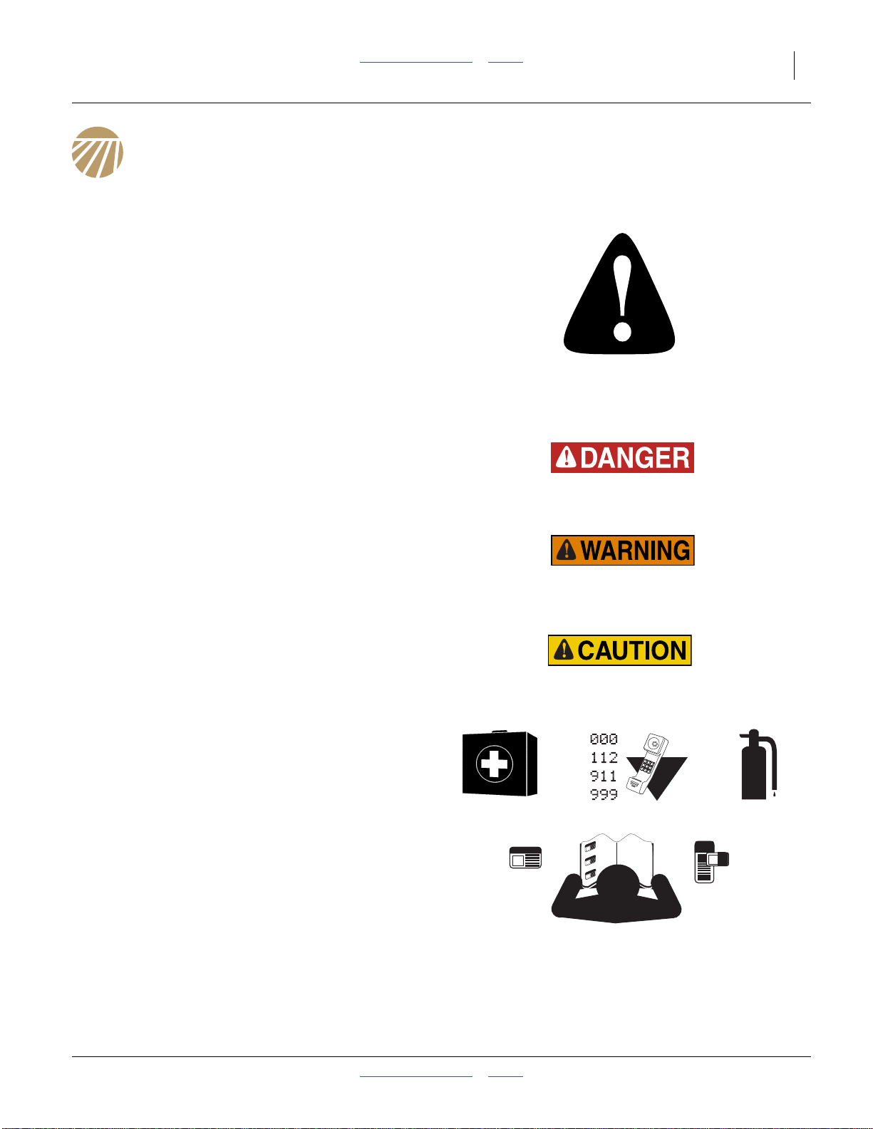
Look for Safety Symbol
The SAFETY ALERT SYMBOL indicates there is a
potential hazard to personal safety involved and extra
safety precaution must be taken. When you see this
symbol, be alert and carefully read the message that
follows it. In addition to design and configuration of
equipment, hazard control and accident prevention are
dependent upon the awareness, concern, prudence and
proper training of personnel involved in the operation,
transport, maintenance and storage of equipment.
Be Aware of Signal Words
Signal words designate a degree or level of hazard
seriousness.
DANGER indicates an imminently hazardous situation
which, if not avoided, will resultin death or serious injury.
This signal word is limitedto themost extreme situations,
typically for machine components that, for functional
purposes, cannot be guarded.
WARNING indicates a potentially hazardous situation
which, if not avoided, could result in death or serious
injury, and includes hazards that are exposed when
guards are removed.It may also be used to alert against
unsafe practices.
CAUTION indicates a potentially hazardous situation
which, if not avoided, may result in minor or moderate
injury. It may also be used to alert against unsafe
practices.
Prepare for Emergencies
▲ Be prepared if a fire starts
▲ Keep a first aid kit and fire extinguisher handy.
▲ Keep emergency numbers for doctor, ambulance, hospital
and fire department near phone.
Be Familiar with Safety Decals
▲ Read and understand “Safety Decals” on page 5,
thoroughly.
▲ Read all instructions noted on the decals.
▲ Keep decals clean. Replace damaged, faded and illegible
decals.
2014-09-09 Table of Contents Index 401-312M
Page 6
2 3PYP Table of Contents Index Great Plains Manufacturing, Inc.
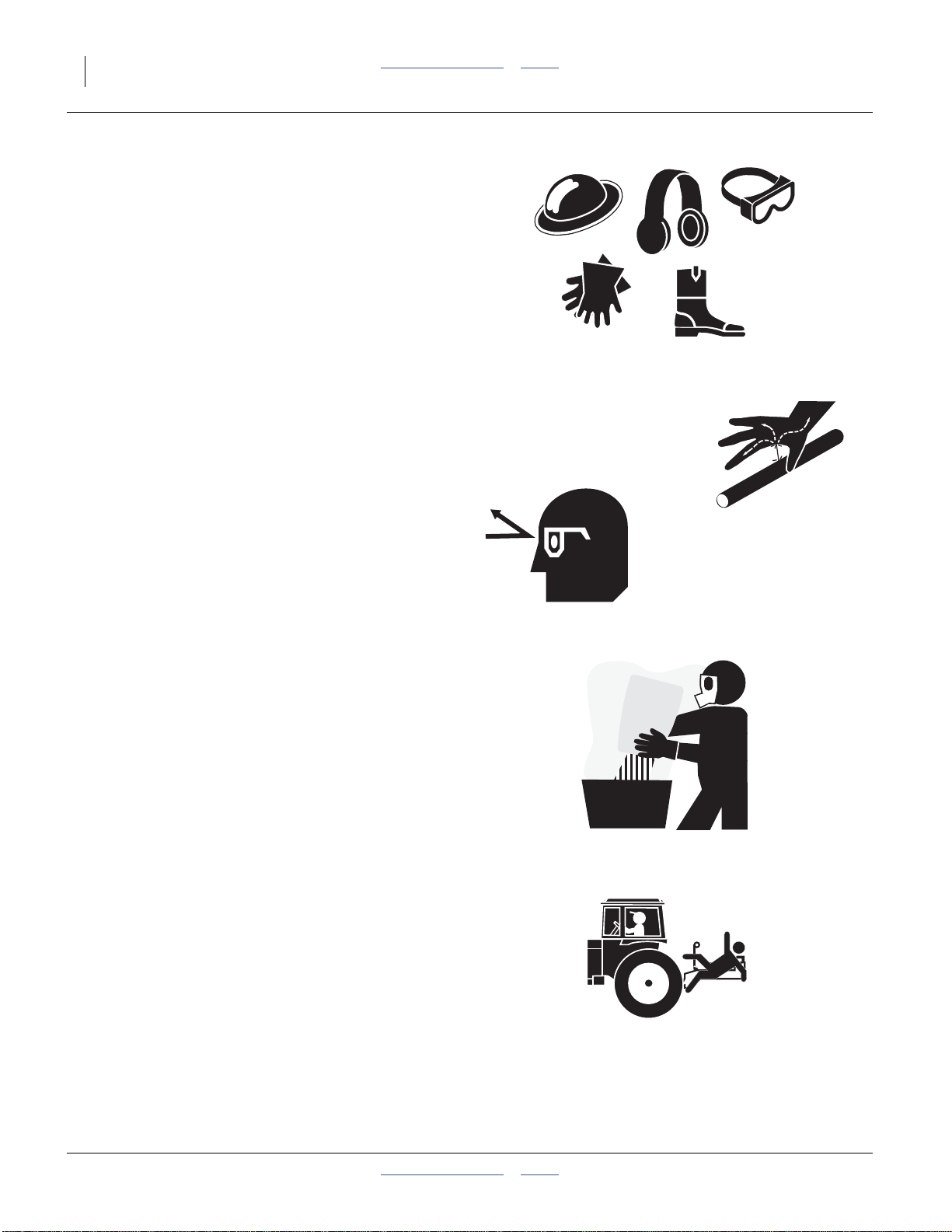
Wear Protective Equipment
▲ Wear protective clothing and equipment.
▲ Wear clothing and equipment appropriate for the job. Avoid
loose-fitting clothing.
▲ Because prolonged exposure to loud noise can cause
hearing impairment or hearing loss, wear suitable hearing
protection such as earmuffs or earplugs.
▲ Because operating equipment safely requires your full
attention, avoid wearing entertainment headphones while
operating machinery.
Avoid High Pressure Fluids
Escaping fluid under pressure can penetrate the skin,
causing serious injury.
▲ Avoid the hazard byrelieving pressure before disconnecting
hydraulic lines.
▲ Use a piece of paper or cardboard, NOT BODY PARTS, to
check for suspected leaks.
▲ Wear protective gloves and safety glasses or goggles when
working with hydraulic systems.
▲ If an accident occurs, seek immediate medical assistance
from a physician familiar with this type of injury.
Handle Chemicals Properly
Agricultural chemicals can be dangerous. Improper use
can seriously injure persons, animals, plants, soil and
property.
▲ Read and follow chemical manufacturer’s instructions.
▲ Wear protective clothing.
▲ Handle all chemicals with care.
▲ Avoid inhaling smoke from any type of chemical fire.
▲ Store or dispose of unused chemicals as specified by
chemical manufacturer.
Keep Riders Off Machinery
Riders obstruct the operator’s view. Riders could be
struck by foreign objects or thrown from the machine.
▲ Never allow children to operate equipment.
▲ Keep all bystanders away from machine during operation.
401-312M Table of Contents Index 2014-09-09
Page 7
Great Plains Manufacturing, Inc. Table of Contents Index Important Safety Information 3
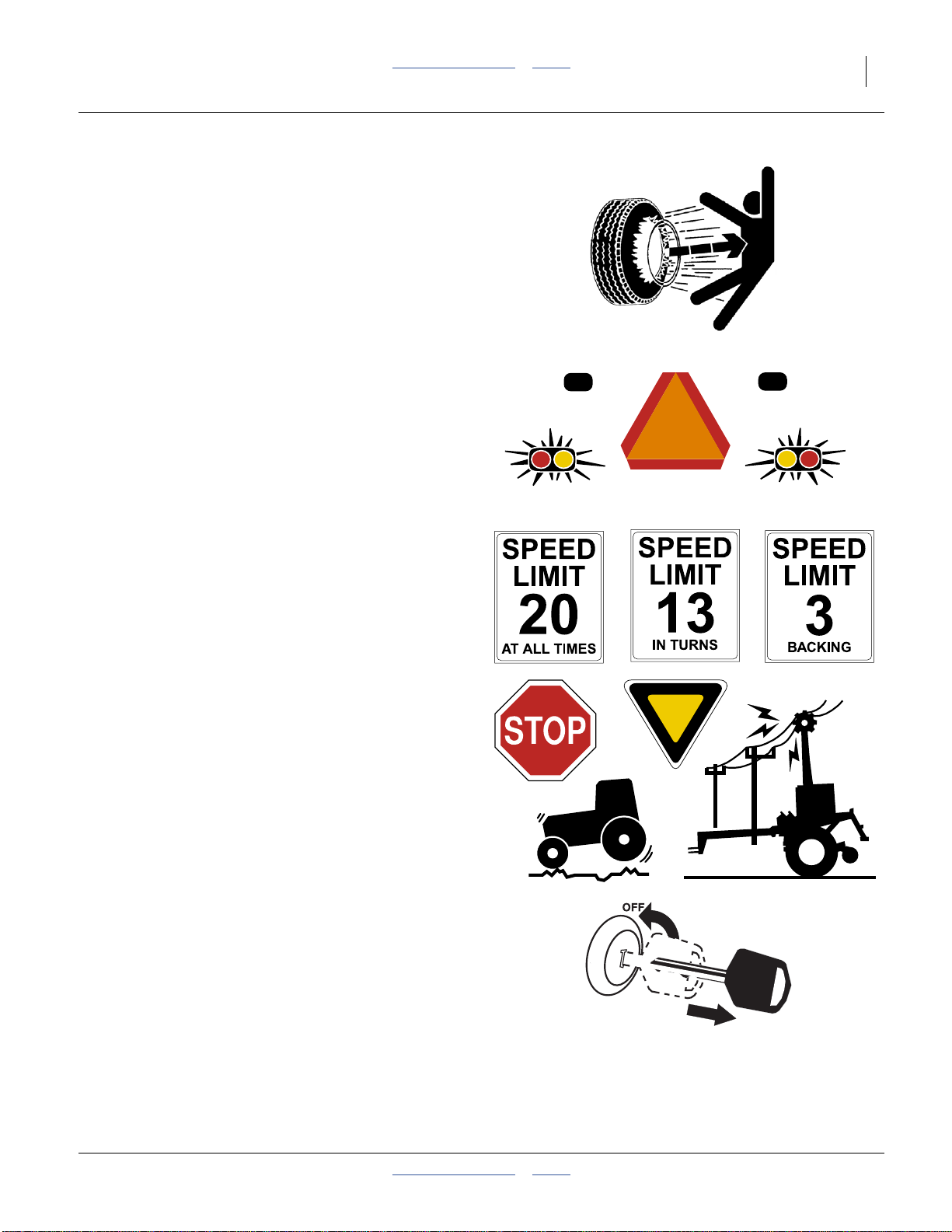
Tire Safety
Tire changing can be dangerous and should be
performed by trained personnel using correct tools and
equipment.
▲ When inflating tires, use a clip-on chuck and extension hose
long enough for you to stand to one side–not in front of or
over tire assembly. Use a safety cage if available.
▲ When removing and installing wheels, use wheel-handling
equipment adequate for weight involved.
Use Safety Lights and Devices
Slow-moving tractors and towed implements can create
a hazard when driven on public roads. They are difficult
to see, especially at night.
▲ Use flashing warning lights and turn signals whenever
driving on public roads.
Use lights and devices provided with implement
Transport Machinery Safely
Maximum transport speed for implement is 20 mph
(32 kph), 13 mph (22 kph) in turns. Some rough terrains
require a slower speed. Sudden braking can cause a
towed load to swerve and upset.
▲ Do not exceed 20 mph. Never travel at a speed which does
not allow adequate controlof steering and stopping. Reduce
speed if towed load is not equipped with brakes.
▲ Comply with state and local laws.
▲ Do not tow an implement that, when fully loaded, weighs
more than 1.5 times the weight of towing vehicle.
▲ Carry reflectors or flags to mark planter in case of
breakdown on the road.
▲ Keep clear of overhead power lines and other obstructions
when transporting. Refer to transport dimensions under
“Specifications and Capacities” on page 124.
▲ Do not fold or unfold the planter while the tractoris moving
Shutdown and Storage
▲ Lower planter, put tractor in park, turn off engine, and
remove the key.
▲ Secure planter using blocks and supports provided.
▲ Detach and store planter in an area where children
normally do not play.
2014-09-09 Table of Contents Index 401-312M
Page 8
4 3PYP Table of Contents Index Great Plains Manufacturing, Inc.
Practice Safe Maintenance
▲ Understand procedure before doing work. Use proper tools
and equipment. Refer to this manual for additional
information.
▲ Work in a clean, dry area.
▲ Lower the planter, put tractor in park, turn off engine, and
remove key before performing maintenance.
▲ Make sure all moving parts have stopped and all system
pressure is relieved.
▲ Allow planter to cool completely.
▲ Disconnect battery ground cable (-) before servicing or
adjusting electrical systems or before welding on planter.
▲ Inspect allparts. Make sure parts are in good condition and
installed properly.
▲ Remove buildup of grease, oil or debris.
▲ Remove all tools and unused parts from planter before
operation.
Safety At All Times
Thoroughly read and understand the instructions in this
manual before operation. Read all instructions noted on
the safety decals.
▲ Be familiar with all planter functions.
▲ Operate machinery from the driver’s seat only.
▲ Do not leave planter unattended with tractor engine
running.
▲ Do not dismount a moving tractor. Dismounting a moving
tractor could cause serious injury or death.
▲ Do not stand between the tractor and planter during
hitching.
▲ Keep hands, feet and clothing away from power-driven
parts.
▲ Wear snug-fitting clothing to avoid entanglement with
moving parts.
▲ Watch out for wires, trees, etc., when folding and raising
planter. Make sure all persons are clear of working area.
401-312M Table of Contents Index 2014-09-09
Page 9
Great Plains Manufacturing, Inc. Table of Contents Index Important Safety Information 5
Safety Decals
Safety Reflectors and Decals
Your implement comes equipped with all lights, safety
reflectors and decals in place. They were designed to
help you safely operate your implement.
▲ Read and follow decal directions.
▲ Keep lights in operating condition.
▲ Keep all safety decals clean and legible.
▲ Replace all damaged or missing decals. Order new decals
from your Great Plains dealer. Refer to this section for
proper decal placement.
▲ When ordering new parts or components, also request
corresponding safety decals.
818-055C
To install new decals:
1. Clean the area on which the decal is to be placed.
2. Peel backing from decal. Press firmly on surface,
being careful not to cause air bubbles under decal.
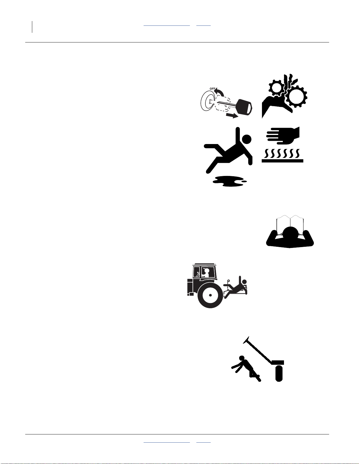
Slow Moving Vehicle Reflector
On the back of the planter walkboard;
one total
838-266C
Red Reflectors
On the back of seed box support structure each end
(above wheels) and on the back of the wing tool bars,
each end, two each side:
four total
25051
25051
2014-09-09 Table of Contents Index 401-312M
Page 10
6 3PYP Table of Contents Index Great Plains Manufacturing, Inc.
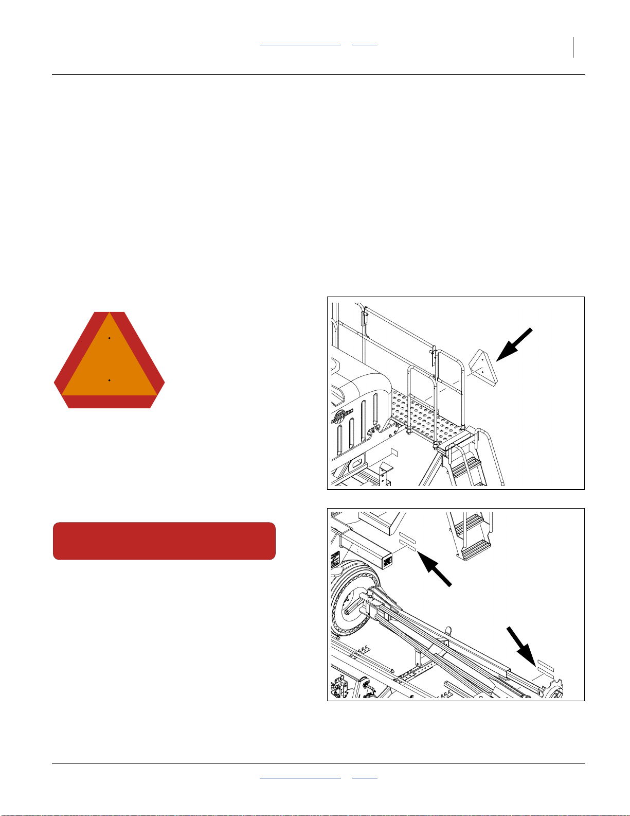
838-265C
Amber Reflectors
On the front of tool bar, at each end and near wing
separation point;
four total.
25051
838-267C
Daytime Reflectors
On the back of seed box support structure each end
(above wheels) and on the back of the wing tool bars,
each end and near separation;
six total.
818-590C
Danger: Crushing Hazard
On tool bar inboard of parking stand,
each side, two total
25051
25051
401-312M Table of Contents Index 2014-09-09
Page 11
Great Plains Manufacturing, Inc. Table of Contents Index Important Safety Information 7
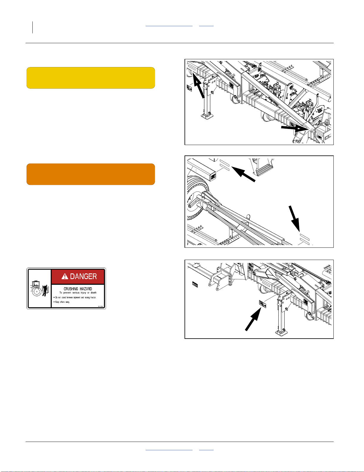
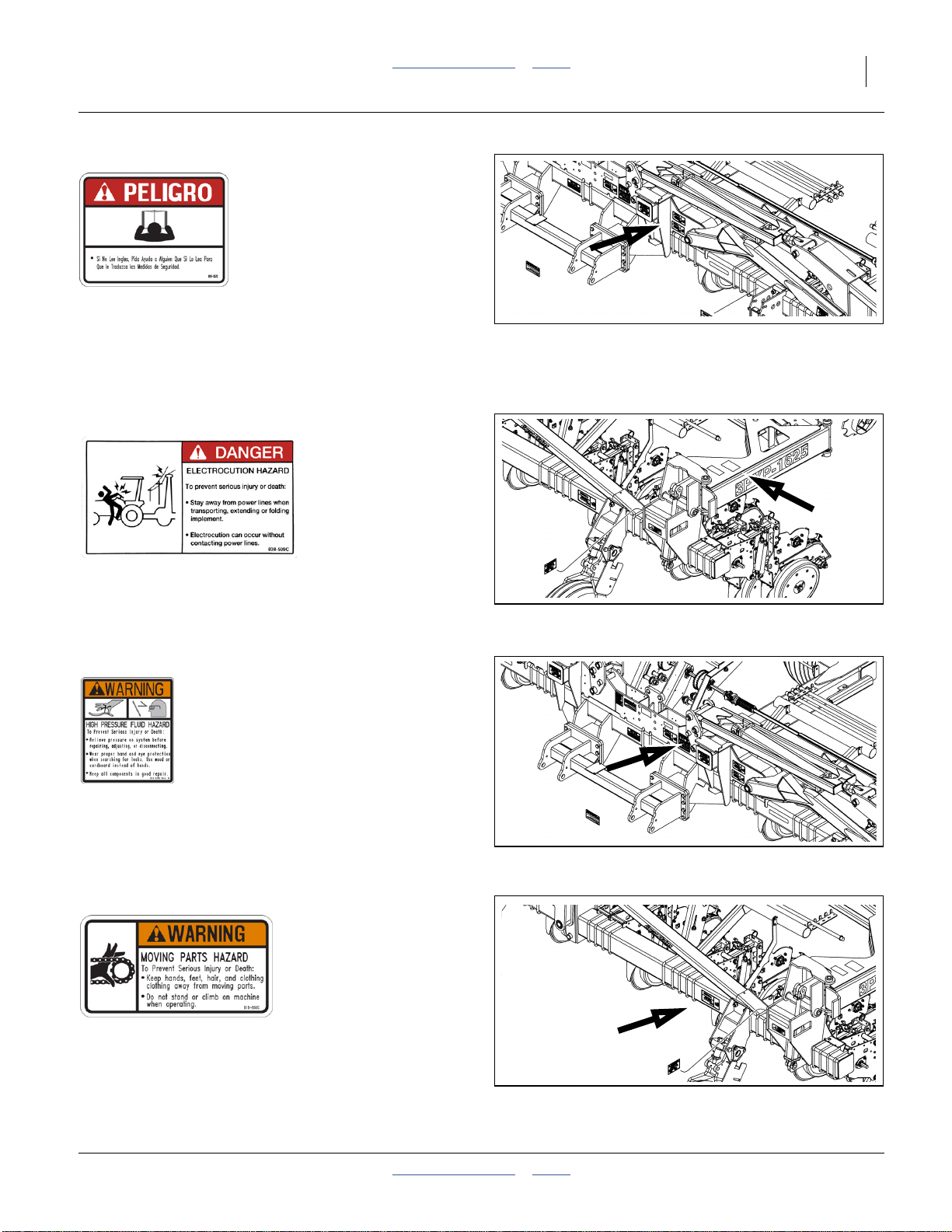
818-557C
25051
Danger (in Spanish):
Advising non-English readers to seek translation.
On front of center section;
one total
838-599C
Warning: Electrocution Hazard
On marker section each end;
two total
818-339C
Warning: High Pressure Fluid Hazard
On on each end of center tool bar, and front of center
section;
three total
818-860C
25051
25051
Warning: Moving Parts
On tool bar inboard of gauge wheel each side,
two total
2014-09-09 Table of Contents Index 401-312M
25051
Page 12
8 3PYP Table of Contents Index Great Plains Manufacturing, Inc.
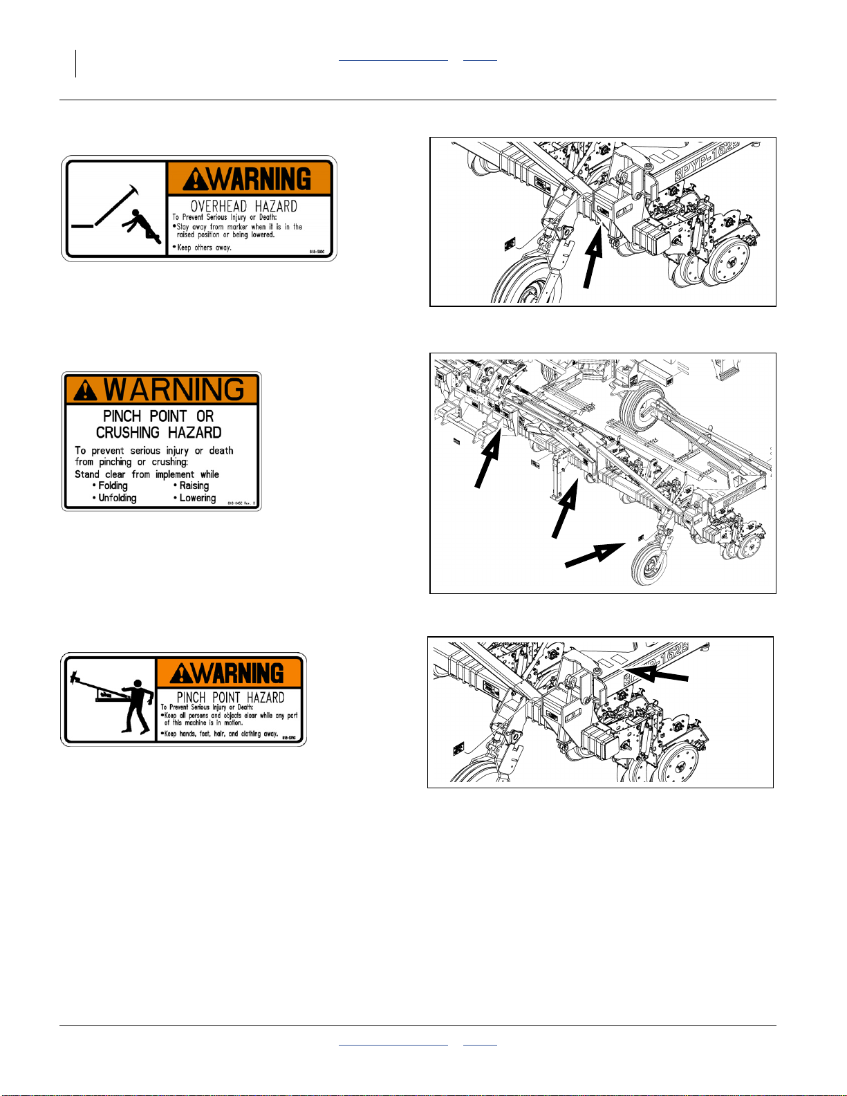
818-580C
Warning: Overhead Hazard
On marker section each end;
two total
818-045C
Warning: Pinch/Crush
On marker base, inside face, each end,
On wing arm link, each side
On wing rest, each side;
six total
818-579C
25051
25051
Warning: Pinch/Shear Hazard
Front face of marker base bracket;
two total
401-312M Table of Contents Index 2014-09-09
25051
Page 13
Great Plains Manufacturing, Inc. Table of Contents Index Important Safety Information 9
818-188C
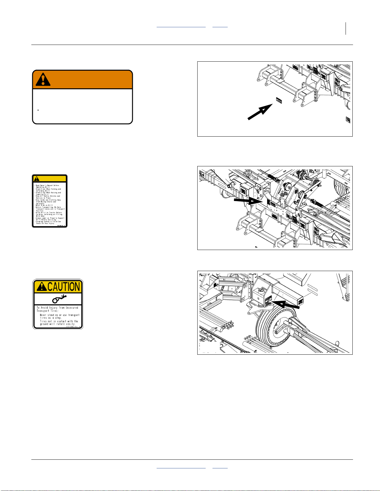
WARNING
EXCESSIVE SPEED HAZARD
To Prevent Serious Injury or Death:
Do Not exceed 20 mph maximum transport
speed. Loss of vehicle control and/or machine
can result.
Warning: Speed
On front of center section;
one total
818-078C
CAUTION
818-188C Rev. C
25051
Caution: Read Operator’s Manual
On center tool bar;
one total
818-398C
Caution: Tires Not A Step
Above all four tires;
four (4) total
25051
25051
2014-09-09 Table of Contents Index 401-312M
Page 14
10 3PYP Table of Contents Index Great Plains Manufacturing, Inc.
Introduction
Great Plains welcomes you to its growing family of new
product owners. The 3-Point 40-Foot Yield-Pro® Planter
(3PYP) has been designed with care and built by skilled
workers using quality materials. Proper setup,
maintenance, and safe operating practices will help you
get years of satisfactory use from the machine.
Description of Unit
The 3PYP is a semi-mounted implement for use in
conventional till, minimum-till, or light no-till conditions.
The 3PYP accepts optional unit mounted coulters. The
unit mounted coulters make it suitable for light to
moderate no-till conditions only. The 3PYP is outfitted
with 25 Series, side-depth-control row-units. The 3PYP
stack-folds for transport.
Intended Usage
Use the 3PYP to seed production-agriculture crops only.
Do not modify the planter for use with attachments other
than Great Plains options and accessories specified for
use with the 3PYP.
Note: This manual covers allvintages of3PYP planters
(does not include model 3PYPA with Air-Pro
meters). Not all illustrations and photographs
represent the most recent products.
®
Document Family
401-312M Operator Manual (this document)
401-312B Seed Rate Charts
401-312P Parts Manual
401-312Q Pre-Delivery Manual
110011425 Quick-Start Guide, 24 twin row
110011427 Quick-Start Guide, 32 twin row
110011468 Quick-Start Guide, 16-row
110011469 Quick-Start Guide, 12-row
110011375 IIntelliAg® Operator manual
Covered Models
3PYP-1236 12 Row, 36-Inch Spacing
3PYP-1238 12 Row, 38-Inch Spacing
3PYP-1240 12 Row, 40-Inch Spacing
3PYP-1630 16 Row, 30-Inch Spacing
3PYP-2320 23 Row, 20-Inch Spacing
3PYP-24TR36 24 Row (12 Twin), 36-Inch Spacing
3PYP-24TR38 24 Row (12 Twin), 38-Inch Spacing
3PYP-24TR40 24 Row (12 Twin), 40-Inch Spacing
3PYP-3115 31 Row, 15-Inch Spacing
3PYP-32TR30 32 Row (16 Twin), 30-Inch Spacing
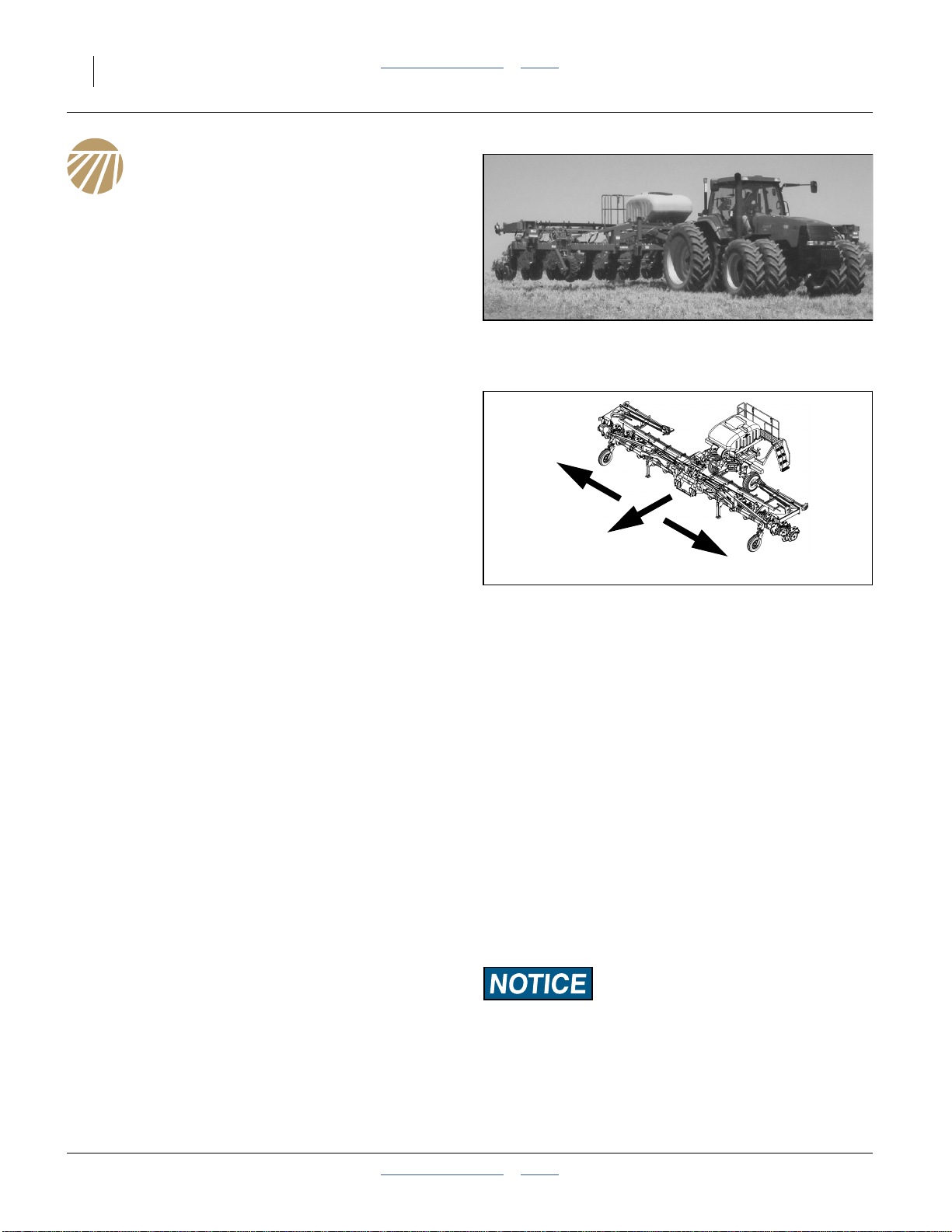
Figure 1
3PYP Planter
29192
R
L
Figure 2
Right / Left
Using This Manual
This manual will familiarize you with safety, assembly,
operation, adjustments, troubleshooting, and
maintenance. Read this manual and follow the
recommendations to help ensure safe and efficient
operation.
The information in this manual is current at printing.
Some parts may change to assure top performance.
Definitions
The following terms are used throughout this manual.
Right-hand and left-hand as used in this manual are
determined by facing the direction the machinewill travel
while in use unless otherwise stated.
A crucial point of information related to the pr eceding topic.
Read and follow the directions to r emain safe , avoid serious
damage to equipment and ensure desired field results.
Note: Useful information related to the preceding topic.
25050
401-312M Table of Contents Index 2014-09-09
Page 15
Great Plains Manufacturing, Inc. Table of Contents Index Introduction 11
Owner Assistance
If you need customer service or repair parts, contact a
Great Plains dealer. They have trained personnel, repair
parts and equipment specially designed for Great Plains
products.
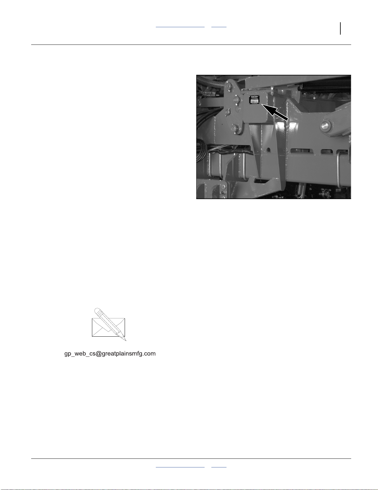
Refer to Figure 3
Your machine’s parts were specially designed and
should only be replaced with Great Plains parts. Always
use the serial and model number when ordering parts
from your Great Plains dealer.The serial-number plate is
located on the front face of the left wing rest near
machine center.
Record your 3PYP model and serial number here for
quick reference:
Model Number:__________________________
Serial Number: __________________________
Your Great Plains dealer wants you to be satisfied with
your new machine. If you do not understand any part of
this manual orare not satisfiedwith the service received,
please take the following actions.
1. Discuss the matter with your dealership service
manager.Make sure they areawareof any problems
so they can assist you.
2. If you are still unsatisfied, seek out the owner or
general manager of the dealership.
For further assistance write to:
Figure 3
Serial Number Plate
29189
Product Support
Great Plains Mfg. Inc., Service Department
Salina, KS 67402-5060
PO Box 5060
785-823-3276
2014-09-09 Table of Contents Index 401-312M
Page 16

12 3PYP Table of Contents Index Great Plains Manufacturing, Inc.
Preparation and Setup
This section helpsyou prepare your tractor and3PYP for
use, and covers tasks thatneed tobe doneonly onceper
hitch, seasonally, or when the tractor/planter
configuration changes.
Before using the 3PYP in the field, you must hitch the
planter to a suitable tractor, inspect systems, level the
planter. Before using the planter for the first time, and
periodically thereafter, certain adjustments and
calibrations are required.
Initial Setup
Prior to first use, and if the tractor changes, these items
need to be completed:
• Install tractor cab consoles (page 148).
• Set initial down-pressure (option, page 155).
• Check center section and wing level (page 157).
• Install Options not factory- or dealer-installed.
Pre-Setup Checklist
1. Read and understand “Important Safety
Information” on page 1.
2. Check that all working parts are moving freely, bolts
are tight, and cotter pins are spread.
3. Check that all grease fittings are in place and
lubricated. Refer to “Lubrication” on page 107.
4. Check that all safety decals and reflectors are
correctly located and legible. Replace if damaged.
See “Safety Decals” on page 5.
5. Inflate tires to pressure recommended and tighten
wheel bolts as specified. See “Tire Inflation Chart”
on page 125.
401-312M Table of Contents Index 2014-09-09
Page 17
Great Plains Manufacturing, Inc. Table of Contents Index Preparation and Setup 13
Hitching Tractor to Planter
Crushing Hazard:
Do not stand or place any body part between planter and
moving tractor. You may be severely injured or killed by being
crushed between the tractor and planter. Stop tractor engine
and set parking brake before attaching cables and hoses.
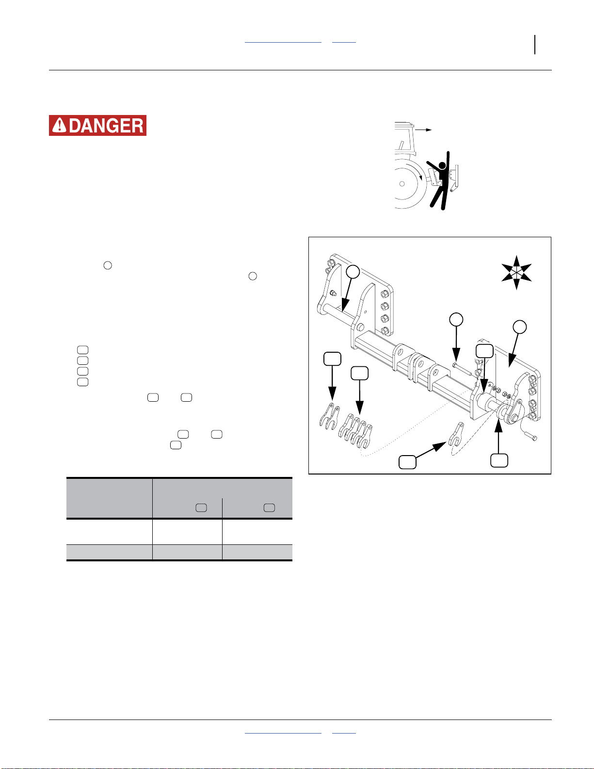
3-Point Hitching
Refer to Figure 4
For older planterswith rowmode spacers, see“Hitching
with Row Mode Spacer” on page 158.
11
12
13
14
Tractor
1
Model
®
11 14
12 13
11
Spacers
14 12
Tube
to Left 1 to Left
1
2
⁄2in
The left arm of the tractor 3-point hitch is secured and
prevented from shifting laterally. The right arm is
allowed to float on the pin.
The objective is to align the planter center-line with the
tractor center-line.
1. The planter includes several spacers to position and
secure the left arm of the 3-point hitch:
1 401-630H SPACER 3 PT 1 1/2 X 2
2 411-442D LOWER 3PT PIN SPACER 1/2 THK
5 411-448D LOWER 3PT PIN SPACER 1/4 THK
1 411-449D TUBE 3" X 1 1/2" X 1/2" LONG
2. The tubespacers ( and ) are always used, and
are typically positioned on the right and left of the
tractor hitch arm.
3. Insert open-end spacers ( and ) to the left of
the smaller tube spacer to achieve center-line
alignment. The following table has recommendations
for specific tractors.
Case IH
Magnum™/MX
John Deere 8000 to Left None
2
3
11
13
12
12
Figure 4
Hitch Spacers
R
F
14
U
B
L
D
1
29861
4. Add a combination of the remaining spacers to
eliminate any slack space on the pin, and minimize
side-to-side play during operations.
5. Secure both sets of spacers with theprovided1⁄2-13
bolts, lock washers and nuts.
2014-09-09 Table of Contents Index 401-312M
Page 18
14 3PYP Table of Contents Index Great Plains Manufacturing, Inc.
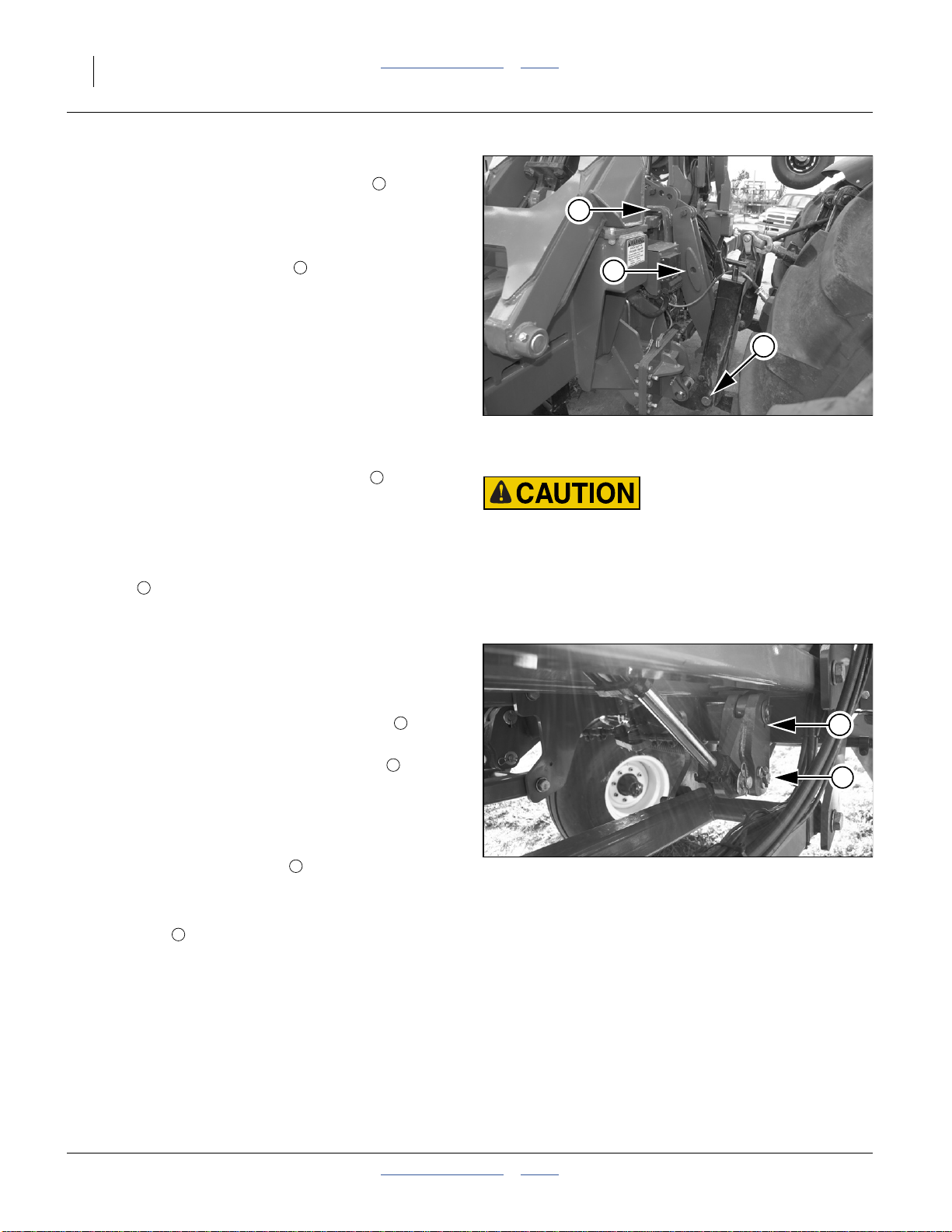
Refer to Figure 5
6. Connect your lower tractor 3-point arms to the
planter 3-point hitch. If using quick hitch be sure
planter locks into hitch securely.
2
4
This is a semi-mounted implement.
• Older models have no top link .
3
3
• 2007+ models have a flexible top link which may be
used, with care, in certain situations.
• If the top link is not used, you may optionally use
lift-assist weight transfer to apply some of the cart
2
weight to the openers during planting.
Refer to Figure 6
If using lift-assist weight-transfer (and not using the
3-point top link), make sure the parallel arms are
configured as follows:
7. Install the lift-assist weight-transfer pins . Thepins
5
Figure 5
Hitching Planter
(Top Link Not In Use)
29211
are stored in a plate behind the cart parallel arm
pivot weldment. Install them in the large holes at the
bottom of the rod-endlug inthe frame-to-cart parallel
arms.
8. Remove the lift-assist shear bolts from the small
6
holes below the lift-assist rod-end lug upper pivot
Excess 3-point weight and steering hazard:
Do not use the top-link and weight-transfer capabilities at the
same time. Planter caster wheels may lift off ground. Tractor
steering wheels may lose effectiveness. An accident is possible,
resulting in serious injury or death, and planter damage.
pin. Store the bolts in the plates behind the cart
parallel arm pivot weldments.
If using the 3-point top link, make sure the parallel arms
are configured as follows:
9. Install the lift-assist shear bolts. Spare bolts are
stored in a plate behind the cart parallel arm pivot
weldment. Secure the bolt in the smallhole below
6
6
the lift-assist rod-end lug upper pivot pin.
10. Removethe lift-assist weight-transfer pins . These
are located at the bottom of the rod-end lug in the
5
5
frame-to-cart parallel arms. The pin is stored in a
plate behind the cart parallel arm pivot weldment.
Refer to Figure 5
11. Connect the flexible top link only for field
operations and maintenance (never for transport).
3
Figure 6
29201
Rod-End Lug Parallel Arm Lug
Adjust the top link with the tractor turnbuckle and the
sliding link .
4
For field operations, adjust the top link so that it is
slack with the planter lowered, and taut near the top
of hitch travel with the planter raised. The goal is to
reduce the weight borne by the rear lift assist
cylinders, and reduce any tendency for the tires to
dig on end-of-pass turns and during backing.
12. Raise tractor 3-point just enough to relieve pressure
from the bases of the parking stands.
401-312M Table of Contents Index 2014-09-09
Page 19
Great Plains Manufacturing, Inc. Table of Contents Index Preparation and Setup 15
Electrical Hookup
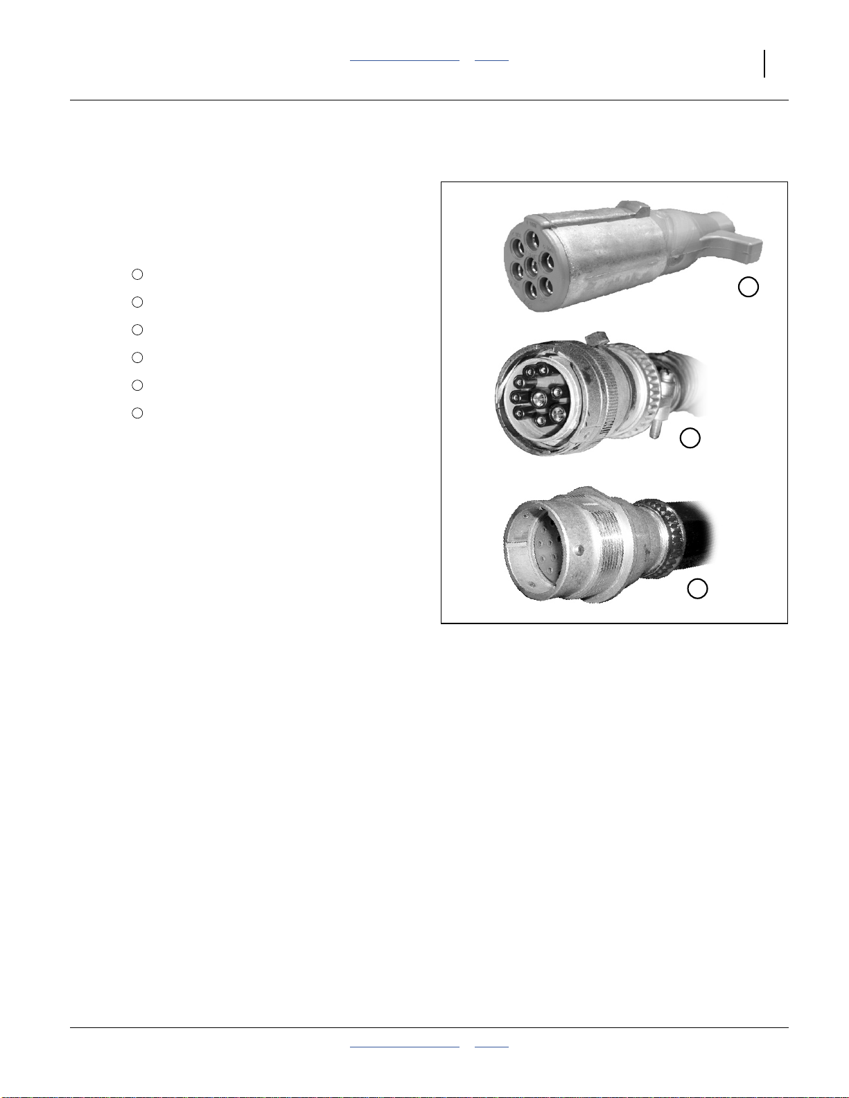
Refer to Figure 7
Your 3PYP is equipped with several standard and
optional devices that require separate electrical
connections. For future reference, note any optional
connections on this checklist.
✔
✔
✔
❑
❑
❑
Lights
1
DICKEY-john
2
Steering ECU
3
___________________________
4
___________________________
5
___________________________
6
®
Planter Control
Make sure tractor isshut down with accessory power off
before making connections.
These connections may be made in any order. The key
requirement is that all connections be made prior to
planter movement.
Note: Switch control boxes should be mounted in your
tractor cab in a location with easy access. Route
wiring harnesses with enough slack to allow for
tractor movement, especially on articulating
tractors.
Figure 7
Connector Identification
1
2
3
25236
25237
25238
2014-09-09 Table of Contents Index 401-312M
Page 20
16 3PYP Table of Contents Index Great Plains Manufacturing, Inc.
Hydraulic Hose Hookup
Only trained personnel should work on system hydraulics!
High Pressure Fluid Hazard:
Escaping fluid under pressure can have sufficient pressure to
penetrate the skin causing serious injury. Avoid the hazard by
relieving pressure before disconnecting hydraulic lines. Use a
piece of paper or cardboard, NOT BODY PARTS, to check for
leaks. Wear protective gloves and safety glasses or goggles
when working with hydraulic systems. If an accident occurs,
seek immediate medical assistance from a physician familiar
with this type of injury.
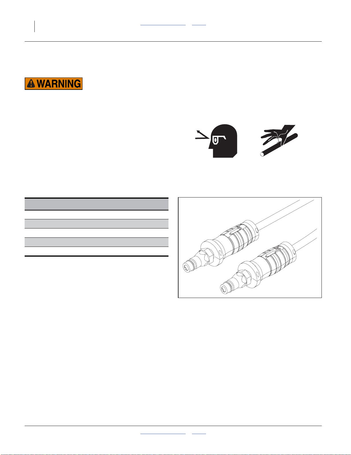
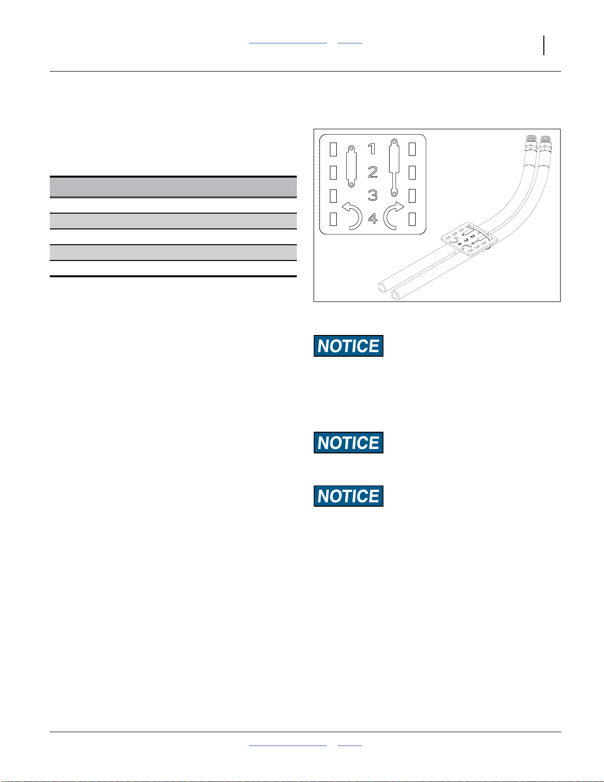
Refer to Figure 8
Great Plains hydraulic hoses are color coded handle
grips to help you hookup hoses to your tractor outlets.
Hoses that go to the same remotevalve are markedwith
the same color.
Current Style Color Coded Hose Handles
Color Hydraulic Function
Steering (no color code)
Black Fan
Green Wing Fold / Marker Tilt/Fold
Blue Lift / Down Pressure
Yellow Hydraulic Drive
To distinguish hoses on the same hydraulic circuit, refer
to the symbol molded intothe handle grip. Hoses with an
extended-cylinder symbol feed cylinder base ends.
Hoses with a retracted-cylinder symbol feed cylinder rod
ends.
For hydraulic fan and drive motors, connect the hose
under the retracted cylinder symbol to the pressure side
of the motor. Connect the hose under the extended
cylinder symbol to the return side of the motor.
The fan motor further requires hookup of a third line,
which returns hydraulic fluid from the fan motor case.
Figure 8
Color Coded Hose Handles
31733
401-312M Table of Contents Index 2014-09-09
Page 21
Great Plains Manufacturing, Inc. Table of Contents Index Preparation and Setup 17
Older Style Hoses with Color Ties
Refer to Figure 9
Great Plains hydraulichoses are color coded to help you
hookup hoses to your tractor outlets. Hoses that go to
the same remote valve are marked with the same color
tie.
Color Hydraulic Function
Steering (no color code)
Orange Fan
White Wing Fold / Marker Tilt/Fold
Blue Lift / Down Pressure
Yellow Hydraulic Drive
To distinguish hoses on the same hydraulic circuit, refer
to plastic hose label. The hose under an
extended-cylindersymbol feeds a cylinder baseend. The
hose under a retracted-cylinder symbol feeds a cylinder
Figure 9
Older Style Hoses with Label
817-348c
17641
rod end.
For hydraulic fan and drive motors, connect the hose
under the retracted cylinder symbol to the pressure side
of the motor. Connect the hose under the extended
cylinder symbol to the return side of the motor.
Motor Seal Damage Risk:
Case Drain Hose must be attached first,
prior to inlet and return hoses being connected.
Protecting Hydraulic Motor Seals
Low Pressure (Case) Drain Connection
1. Attach case drain hose to low pressure drain
connection.
2. Connect low pressure return hose to low pressure
return connector.
3. Connect hydraulic hoses to tractor remotes.
Case Drain Hose must be detached last,
to prevent damage to the fan motor.
Case drain hose must be hooked up first and unhooked
last to prevent damage to hydraulic motor seals.
Hydraulic Motor Performance Risk:
DO NOT connect the case drain line to a
power-beyond-port.
2014-09-09 Table of Contents Index 401-312M
Page 22
18 3PYP Table of Contents Index Great Plains Manufacturing, Inc.
Frame Height and Leveling
All frame sections must beat the correct height and level
to maintain even planting depth.
Periodic frame-leveling adjustments should not be
necessary unless the depth control stop has changed
since last leveling. If you are having problems with
uneven depth, check planter levelness and follow these
procedures.
1. Complete the steps under “BleedingHydraulics”on
page 100, before proceeding.
2. Before first use, and as necessary thereafter,
complete or check:
“Center Section Leveling” on page 157,
“Wing Leveling” on page 157, and
“Hydraulic Down Pressure Calibration” on
page 159.
3. Unfold the planter fully. See “Unfolding The 3PYP”
on page 28.
Note: Older planters with rephasing cylinders need to
have the cylinder rephrased as the first step. See
page 165.
Note: Level frame in planting conditions.
Failure to do so may result in machinery not
producing desired results.
Set Initial Planter Height
The planter is designed to operate with the main tool bar
26 inches (66 cm) above the planting surface (level
ground or bed peaks).
Note: Tractor 3-pointcontrol must be in Depth Control
mode, and not Draft Control mode.
When lowering the planter for the first time on the
planting ground:
4. Completely lower the 3-point.
5. Completely lower the Lift Assist. If necessary, first
raise lift off transport locks, remove and stow locks.
6. Raise the 3-point untilthe toolbar is26 inches above
the planting surface.
7. Set the cab 3-point lever stop to capture this
“lowered” height.
On beds, it will further be necessary to use
customer-supplied blocks to raisethe down-stopposition
of the lift assist cylinders. One way to accomplish this is:
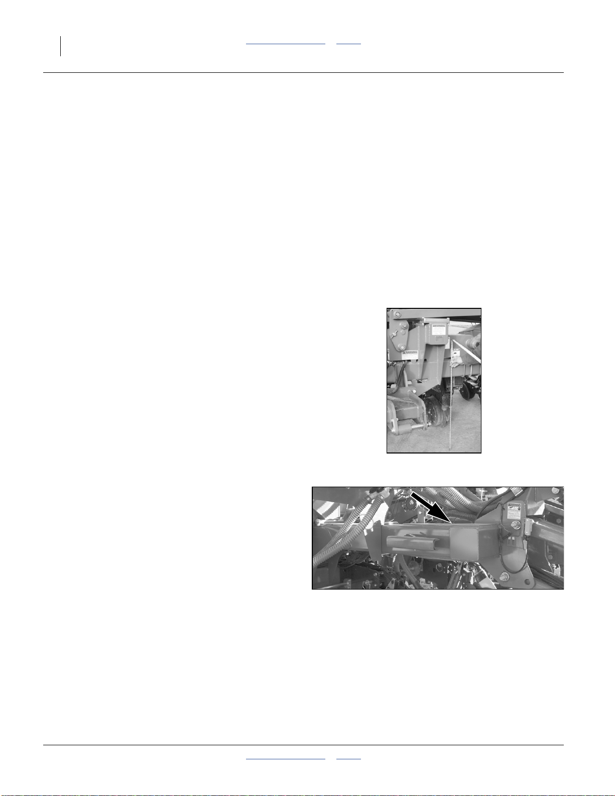
Refer to Figure 11
8. Place a carpenter’s level on aside tube of the center
frame (pointed to in Figure 11). Have an assistant
stand a safe distance away and observe it.
9. With the 3-point lowered to the 26 inch stop,
incrementally raise the lift assist until the frame is
level.
10. Check that the front tool bar is at 26 inches above
planting surface. If not, adjust stop and repeat
step 9.
Figure 10
Setting Hitch/Center Height
Figure 11
Leveling on Beds
11. Measure the length of exposed rod on the lift
cylinders. Provision two (sets of)blocksin that length
(or stacked to that length).
12. Fully raise the lift assist and insert the blocks.
25435
29193
401-312M Table of Contents Index 2014-09-09
Page 23
Great Plains Manufacturing, Inc. Table of Contents Index Preparation and Setup 19
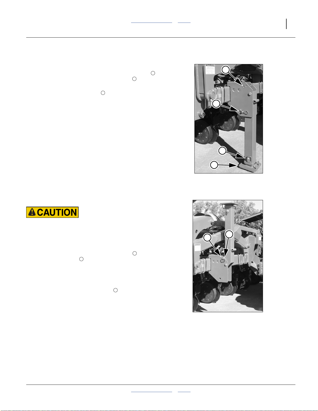
Raise Parking Stands
Refer to Figure 12
1. If not already atminimum length,remove lower pin
of parking stand, fully retract the inner leg , and
re-insert pin.
2. Remove upper (holding) pin of parking stand (at
bottom of hinge bracket).
3
2
1
4
3
1
2
Refer to Figure 13
Falling Object Hazard:
Do not stand directly in front of the stand while raising it. You
need to have one hand free to insert the pin, and if you lose
your grip on the stand, it can swing down and inflict injury.
3. Swing the parking stand forward and up until it is
above the rear hole. Place the holding pin in the
rear-most top hole of the hinge plate. This is the
parking stand position for transport and field
operation.
Note: If 3PYP is equipped with row cleaners, the stand
may not be able toget fullyvertical. It may be
necessary to use front top hole .
4. Secure hosesand cables to that theyhave sufficient
slack for hitch movements, but cannot get caught
between moving parts of planter. Failure to safely
route and secure hoses and cables could result in
damage requiring component repair/replacement,
and lost field time.
4
5
1
Figure 12
Raising Parking Stand
4
Parking Stand Raised
5
Figure 13
25240
25241
2014-09-09 Table of Contents Index 401-312M
Page 24
20 3PYP Table of Contents Index Great Plains Manufacturing, Inc.
Marker Extension
Marker extension needs to beadjusted oncefor the initial
3PYP setup, and later only if changing row spacing
(including locking up row units for single-row operation
on a twin-capable planter).
1. If changing between single- and twin-row operation
on older planters, be sure the Row Mode Spacer
blocks are first set correctly before adjusting
markers. See page 158.
2. Move the planter to a location where both markers
may be safely unfolded. Unfold the planter. Lower
the planter. Tilt up and unfold one marker.
3. Find thesuggested initial marker Extension inthe
following tables.
E
Figure 14
Marker Extension
E
25265
Row Spacing Marker Extension Row Spacing Marker Extension
15 in. (38.1 cm) Single 240 in. (609.6 cm) 36 in. (91.4 cm) Twin-Row 230 in. (584.2 cm)
20 in. (50.8 cm) Single 240 in. (609.6 cm) 38 in. (96.5 cm) Single 247 in. (627.4 cm)
30 in. (76.2 cm) Single 255 in. (647.7 cm) 38 in. (96.5 cm) Twin-Row 243 in. (617.2 cm)
30 in. (76.2 cm) Twin-Row 251 in. (637.5 cm) 40 in. (101.6 cm) Single 260 in. (660.4 cm)
36 in. (91.4 cm) Single 234 in. (594.4 cm) 40 in. (101.6 cm) Twin-Row 256 in. (650.2 cm)
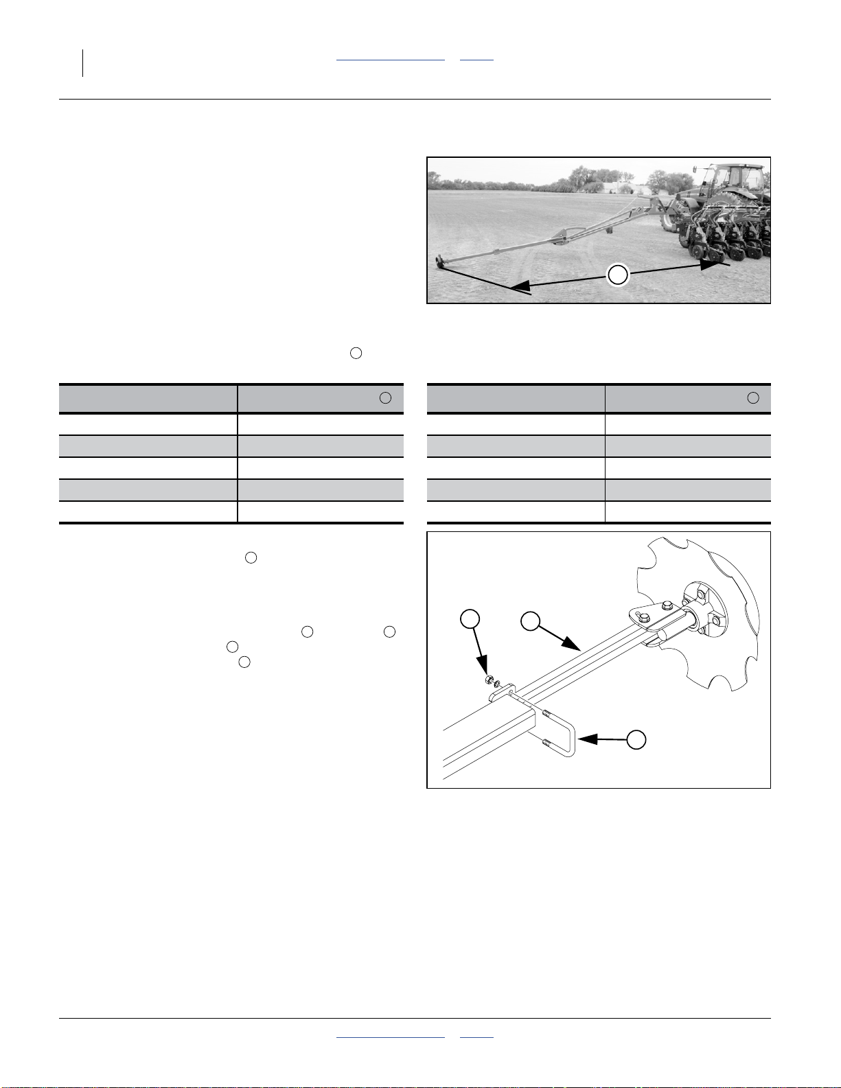
Refer to Figure 14 and Figure 15
4. Measure out the Extension distance from each
outside end row unit (or row unit in use for twin-row
in lock-up). Do not measure to center of row pair.
5. Mark the ground at this point.
6. To adjustmarker width, loosen nuts on U-bolts .
Move marker disk tube in or out to get the proper
adjustment. Tighten nuts .
7. Repeat steps 4 and 6 for the other side.
8. With the planterstill lowered, driveforward a few feet
for each side.
9. Check the mark locations. Adjust to obtain the table
value.
E
1 2
3
1
E E
1
3
2
Figure 15
Marker Extension Adjustment
401-312M Table of Contents Index 2014-09-09
18878
Page 25
Great Plains Manufacturing, Inc. Table of Contents Index 21
Operating Instructions
This section covers general operating procedures.
Experience, machine familiarity, and the following
information will lead to efficient operation and good
working habits. Always operate farm machinery with
safety in mind.
Pre-Start Checklist
Performthe following steps before transportingthe 3PYP
to the field.
High Pressure Fluid Hazard:
Escaping fluid under pressure can have sufficient pressure to
penetrate the skin. Check all hydrauliclines and fittingsbefore
applying pressure. Fluid escaping from a very small hole can
be almost invisible. Use paper or cardboard, not body parts,
and wear heavy gloves to check for suspected leaks. If an
accident occurs, seek immediate medical assistance from a
physician familiar with this type of injury.
❑ Carefully read “Important Safety Information” on
page 1.
❑ Install seed rate meters appropriate for crop. To
change meters, see “Seed Meter Setup and
Adjustment” on page 70.
❑ Install seed wheels appropriate for crop. To change
wheels, see “Singulator Plus™ Meter Wheel
Replacement” on page 72. Make sure correct 6- or
12-finger units are installed for the intended row
spacing.
❑ Lubricate planter as indicated under “Lubrication”
on page 107.
❑ Check all tires for proper inflation. See “Tire
Inflation Chart” on page 125.
❑ Check all bolts, pins, and fasteners. Torque as
shown in “Torque Values Chart” on page 126.
❑ Check planter for worn or damaged parts. Repair or
replace parts before going to the field.
❑ Check hydraulic hoses, fittings, and cylinders for
leaks. Repair or replace before going to the field.
2014-09-09 Table of Contents Index 401-312M
Page 26
22 3PYP Table of Contents Index Great Plains Manufacturing, Inc.
Monitor Operation
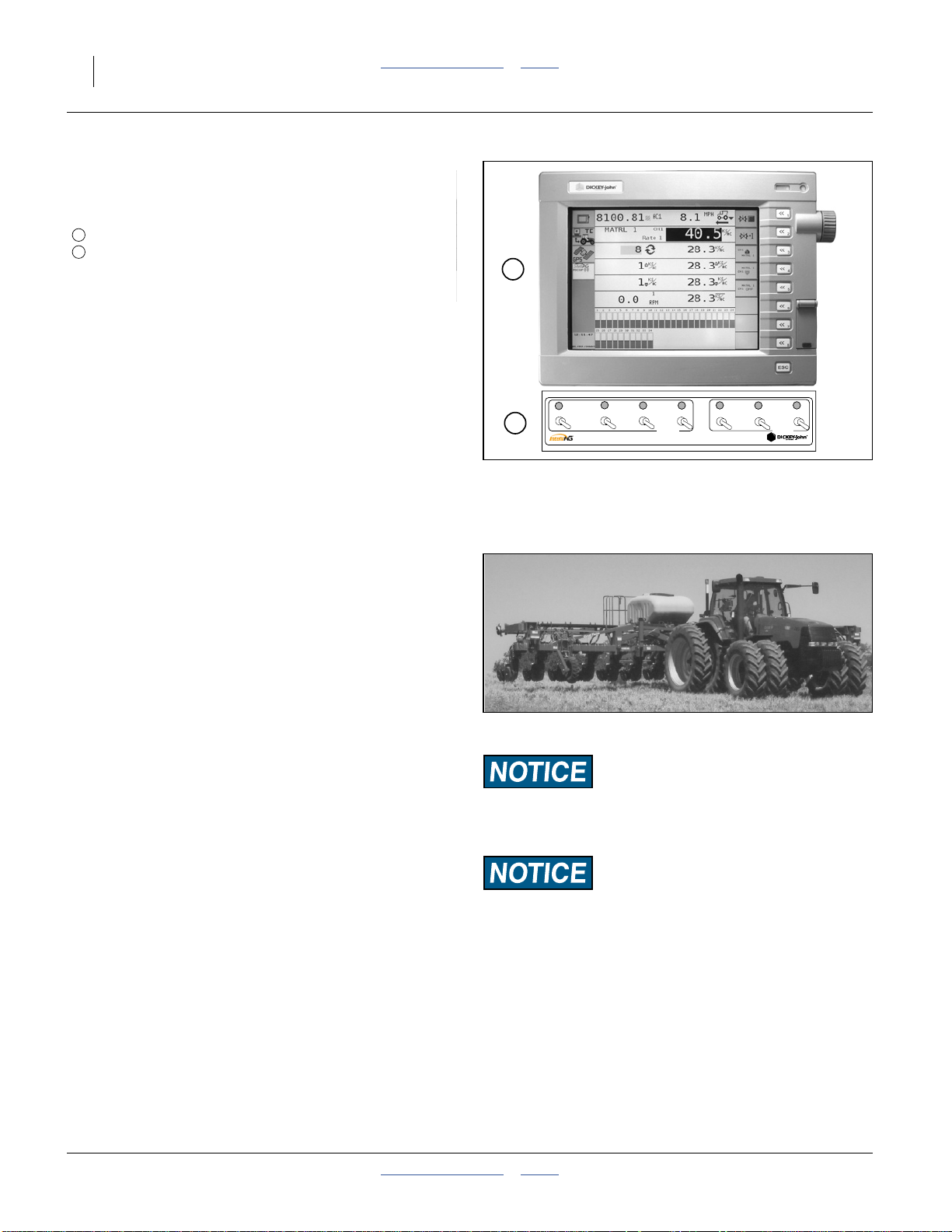
Refer to Figure 16
The monitor system includes two cab components:
1
IntelliAg® seed monitor console, and
2
IntelliAg
Switch panel operations are described in this section.
Monitor console operation is described in a separate
manual supplied with your 3PYP. Operations covered in
that manual (and therefore not in this manual) include:
®
clutch-folding module (switch panel)
1
• hydraulic drive control
(option)
• setting rate limits and
detecting out-of-limits
• seed rate calibration • GPS integration
• planting rate • fan rpm
• fertilizer rate
Raising/Lowering Planter
Refer to Figure 17
(which depicts theplanter bothraised and unfolded)
Planter raising relies on the3-point hitch in front, andthe
Lift Assist cylinders in back. Toraise or lower the planter,
move the levers for both the Lift circuit and the 3-point
hitch.
Great Plains recommends this sequence (to prevent
lateral dragging of wing components):
• in Raising, operate the planter Lift circuit first, and
• in Lowering, operate the hitch circuit first.
The planter may be raisedor lowered in either the folded
or unfolded configuration.
The lift assist circuit may also include the optional down
pressure system. This system engages and disengages
automatically.
MASTER
Left
2
Monitor Console & Panel
Right
Center
CLUTCH
Figure 16
Figure 17
Wing Fold
Marker Tilt
Marker Fold
FRAME
25421
25246
29192
Planter Raised
Machine Damage Risk:
Do not raise orlower whileany planterfolding operations are
underway or partially complete.
Machine Damage Risk:
Always raise planter for reverse/backing operations.
401-312M Table of Contents Index 2014-09-09
Page 27
Great Plains Manufacturing, Inc. Table of Contents Index Operating Instructions 23
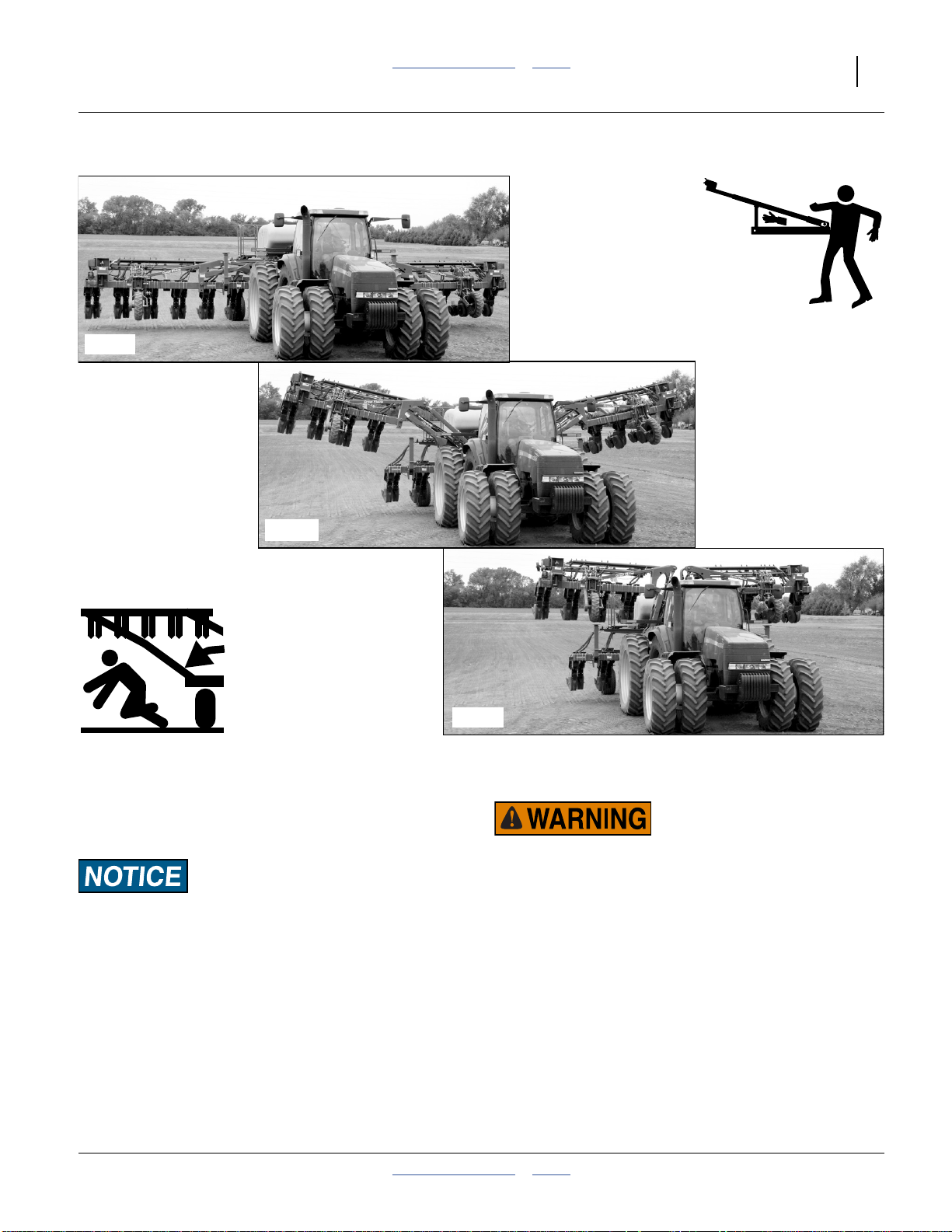
Folding the 3PYP
25243
25244
Figure 18
Planter Folding
Fold the 3PYP for moves between fields and over public
roads. Fold the planter on level ground with the tractor in
park.
Certain Machine Damage:
Machine damage will occur if wing flex and lock pins are not
properly configured for folding. Follow the instructions on the
following pages carefully.
25245
Pinch Point and Crushing Hazard.
To prevent serious injury or death:
▲ Donot allow anyone to beon or near the planter,or beyond
the ends of the planter during unfolding. Numerous pinch
and crush points exist in the mechanism. The wings are
massive. Coulters and row openers are sharp.
▲ Fold only with markers resting in transport cradles.
▲ Fold only if hydraulics are bled free of airand fully charged
with hydraulic oil.
▲ Stay away from frame sections when they are being raised.
▲ Keep away and keep others away when folding planter.
2014-09-09 Table of Contents Index 401-312M
Page 28
24 3PYP Table of Contents Index Great Plains Manufacturing, Inc.
Locking Pins
Refer to Figure 19
Each wing has two removable pins, stored in the parking
1
stand when not in use:
• Wing Lock Pin
Used to connectthe wingtool bar tothe center section
tool barduring planting operations, and keep the wing
tool bar at the same height as the mainframe tool bar.
When this pin is installed at the coupling, the outer
wing is either rigid, or can flex (depending on the
planter “flex” configuration)
• Wing Flex Lock Pin
2
3
1
3
2
Required to stabilize pivot during folding and
unfolding. Used during planting to prevent wing flex.
The following table summarizes pin use.
The
INNER pins must be IN
and the
OUTER pins must be OUT
during folding and unfolding,
or machine damage will result.
Figure 19
Wing Lock Pin Locations
1
2
Figure 20
Wing Lock & Pin Storage
2 1
25248
25247
Pin Location During Comments
Wing Lock Stowed • Planter Folded Must be removed from coupling during folding
Wing Lock Tool bar Coupling • Planting Must be removed from coupling during folding
Flex Lock Stowed • Planting Must be present in pivot during folding and
Flex Lock Wing Arm Pivot • Folding/Unfolding
2
and unfolding or machine damage will result.
2
and unfolding or machine damage will result.
3
unfolding or machine damage will result.
3
• At all times on “Flex Lock”
planters
Must be present in pivot during folding and
unfolding or machine damage will result.
401-312M Table of Contents Index 2014-09-09
Page 29
Great Plains Manufacturing, Inc. Table of Contents Index Operating Instructions 25
MASTER
Left
Center
CLUTCH
Figure 21
Cab Selector Controls
1. Put tractor in Park.
Refer to Figure 19 and Figure 20 onpage 24
2. Make sure the inner wing flex lock pins are in place
in the pivot.
3. Make sure the outer wing lock pinsare out ofthe tool
bar coupling.
Machine Damage Risk:
Wing pins must be inner-in and outer-out during folding and
unfolding wings or machine damage will occur.
Note: No pins are requiredtolockthe planter inthefolded
configuration.
Refer to Figure 24
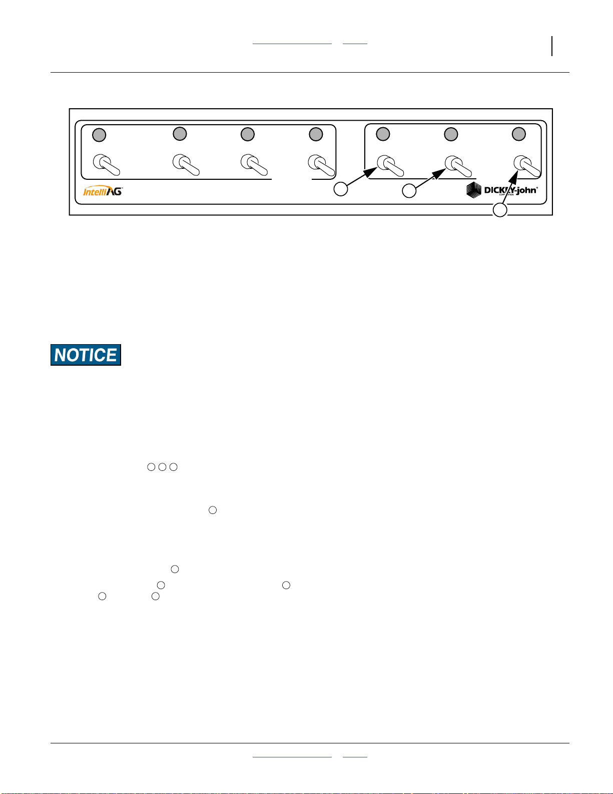
4. Set all DICKEY-john® selector switch module
FRAME switches to off (down).
1 2 3
5. Raise planter (see “Raising/Lowering Planter” on
page 22).
6. Set FRAME switch “Wing Fold” to on (up).
1
7. Activate (normally Extend) tractor hydraulic circuit to
unfold wings.
8. When fully folded, set hydraulic circuit to off.
9. Set “Wing Fold” switch to off.
Note: Wing Fold switch has priority over switches
and . If switch is left on, markeroperations are
3 1
1
1 2
disabled.
Right
2
Marker Tilt
Marker Fold
FRAME
Wing Fold
1
3
25246
2014-09-09 Table of Contents Index 401-312M
Page 30

26 3PYP Table of Contents Index Great Plains Manufacturing, Inc.
Lift Assist Cylinder Lock-Up
When moving the raised planter more than a short
distance, or over any paved surface, do not rely solelyon
the lift cylinders to keep it raised. Install transport locks.
Refer to Figure 22
1. Remove the transport locks from their storage
positions. Do not store the locking pinson theempty
storage tabs.
2. Fully raise the planter (using both 3-point and lift
assist).
3. Remove any height adjusting blocks from the lift
assist cylinders.
4. Install the transport locks on the cylinder rods ,
securing them with the same pins used for storage.
5. Lower the lift assist cylinders onto the locks. Leave
the 3-point raised.
1
2
1
Figure 22
Transport Lock Storage
2
25439
Transport the 3PYP to the field.
Do so only with wings folded and markers stowed.
1. Disconnect 3-point top link
(on 2008+ models with flexible top link).
Loss of Steering Control Hazard:
Never transport with top link connected. When the top link is
adjusted for field work, some of the weight of the planter
mainframe is carried by the top link, which can dangerously
reduce tractor front wheel traction and steering control.
2. Make sure tractor is fueled for the work planned.
3. Before departing, ensure that opener depth and
seed rate have been determined, or that the
necessary data is with you.
4. Close slide gate on hopper or seed box.
Reduction of Control Risk:
Seed may be loaded prior to travel, but increases stopping
distance, increases the need for caution in turns and braking,
and increases tire wear.
5. Hitch, making electrical and hydraulic connections.
These steps are described beginning at “Hitching
Tractor to Planter” on page 13.
6. If markers are unfolded, fold them per the
instructions on page 34. If markers are tilted up, tilt
them down intotheir cradles per “Marker Tilt-Down”
on page 34.
7. Raise planter.
25249
401-312M Table of Contents Index 2014-09-09
Page 31

Great Plains Manufacturing, Inc. Table of Contents Index Operating Instructions 27
8. Install cylinder lock-up channels on lift assists. See
“Lift Assist Cylinder Lock-Up” on page 26
9. If planter wings are unfolded, fold them. See
“Folding the 3PYP” on page 23
10. Always have lights on for highway operation.
11. Comply with all federal, state and local safety laws
when traveling on public roads.
12. Travel with caution.
Transport Hazard:
Do not exceed 20 mph, or the posted speed limit (whichever is
lower) when driving straight.
Transport Hazard:
Do not exceed 13 mph, or the posted speed limit (whichever is
lower) in turns.
13. Keep Clearances in mind. Folded, your 3PYP may
be over 25 ft wide and over 121⁄2ft. high.
Steering
Never exceed 13 mph (22 kph) in turns. The 3PYP is
extremely heavy, and can cause “over-steer” with most
tractors. Above 8 mph the rear wheels caster and
provide only modest resistance to side sway by the
planter.
If not equipped with Steering, the rear wheels on the
3PYP are full castering at all times.
If your 3PYP is equipped with hydraulic Steering, it is
normally engaged at all times when speed is less than
8 mph. Although not used during forward motion in
transport, it MUST be engaged for any backing. See
“Steering” on page 151
Never exceed 3 mph (5 kph) in reverse.
Machine Damage Risk:
Never back up with the planter lowered.
Machine Damage Risk:
If planter has optional steering, never back up without
steering engaged.
2014-09-09 Table of Contents Index 401-312M
Page 32

28 3PYP Table of Contents Index Great Plains Manufacturing, Inc.
Unfolding The 3PYP
25245
25244
25243
Figure 23
Planter Unfolding
Crushing, Pinch-Point and Overhead Hazards To prevent serious injury or death:
▲ Do notallow anyone tobe on or nearthe planter, orbeyond
the ends of the planter during unfolding. Numerous pinch
and crush points exist in the mechanism. The wings are
massive. Coulters and row openers are sharp.
▲ Unfold only if hydraulics are bled free of air and fully
charged with hydraulic oil.
▲ Unfold only with markers resting in transport cradles.
401-312M Table of Contents Index 2014-09-09
Page 33

Great Plains Manufacturing, Inc. Table of Contents Index Operating Instructions 29
MASTER
Left
Center
CLUTCH
Figure 24
Cab Selector Controls
1. Move planter to an area of level ground.
Put tractor in Park.
2. Unless rechecked recently, level the planter per the
instructions on “Frame Height and Leveling” on
page 18.
Refer to Figure 25
3. Make sure wing flex lock pins are in place.
4
Certain Machine Damage:
Wing flex lock pins must be in place during folding and
4
unfolding wings or machine damage will occur.
4. Verify that the wing lock pins are available, and
5
are not in the wing lock-down holes. Normally, in
storage, transport and set-up, these pins are stored
in dedicated holes in the parking stand bracket .
6
Note: If the lock pins are stored in the lock holes, the
wings will not fully deploy.
Refer to Figure 24
5. Set all DICKEY-john® selector switch module
FRAME switches to off (down).
1 2 3
6. Raise planter.
7. Set FRAME switch “Wing Fold” to on (up).
3
8. Activate (normally Extend) tractor hydraulic circuit to
unfold wings.
9. When fully unfolded, set hydraulic circuit to off.
10. Set“Wing Fold” switch to off (ormarker operations
3
will be disabled).
Refer to Figure 26
11. Insert wing lock pins .
5
If operation willbe over uneven ground, remove wing flex
lock pins , and store in parking stand bracket holes.
4
Right
2
Marker Tilt
Marker Fold
FRAME
Wing Fold
1
3
25246
6
5
Figure 25
Flex Lock & Pin Storage
25247
4
4
Figure 26
Wing Lock Pin Locations
25248
2014-09-09 Table of Contents Index 401-312M
Page 34

30 3PYP Table of Contents Index Great Plains Manufacturing, Inc.
Electric Clutch Operation
MASTER
Left
Center
CLUTCH
Figure 27
Cab Selector Controls
Your planter has two or three clutches in the meter drive
system. Each clutch enables or disables groups of row
units (see table next page). This mode of operation may
be needed, for example, for planting a pass that isn’t the
full width of the machine.
Which row units are controlled by the clutch switches
depends on how your row units are driven.On
ground-drive machines, the Left/Right switches control
only the wingrow units. Onhydraulic-drive machines, the
Left/Right switches each control half the row units (and
the Center switch has no function).
The Master switch controls all row units, regardless of
drive type. For all switches, “OFF” (down) removes power
from the clutch, disengaging that set of row units.
Electric Clutch Lock-Up
In case of electric clutch failure, an electric clutch can be
mechanically engaged.
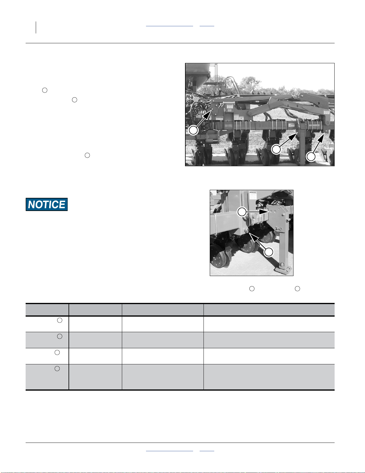
Refer to Figure 28 and Figure 29
1. Remove the three M8-1.25x14 mm metric bolts
from their storagelocations nearthe clutch.Savethe
nuts.
2. At the clutch, align the cutouts with the holes .
3. Insert the M8-1.25×14 mm metric bolts .
2 3
1
If you observe half the hole obstructed by a metal
4
disc , you are not at a cutout.
If the entire hole is obstructed by ametal disc , you are
not at a cutout.
When at a cutout, the bolt will screw in with minimal
resistance until the bolt head reaches the clutch face.
Note: Use only the provided 14 mm length bolts. Longer
bolts will damagethe clutch.Shorterbolts may not
effect a lock-up. Replacement bolts are Great
Plains part number 802-782C.
1
4
Right
Wing Fold
Marker Tilt
FRAME
Figure 28
Electric Clutch Lockup
4
3
2
Figure 29
Clutch Plate Nearly at Cutout
Marker Fold
25246
1
29329
26168
401-312M Table of Contents Index 2014-09-09
Page 35

Great Plains Manufacturing, Inc. Table of Contents Index Operating Instructions 31
CLUTCH
Right
Wing Fold
MASTER
Left
Center
Clutch Switch Coverage
12-row Ground Drive (36 in. Single, 38 in. Single, 40 in. Single)
Left Center
123456789
Right
10111
2
12-Row Hydraulic Drive (36 in. Single, 38 in. Single, 40 in. Single)
Left Right
123456789
16-row Ground Drive (30 in. Single)
10111
2
Left Center Right
123456789
16-Row Hydraulic Drive (30 in. Single)
1011121314151
6
Left Right
123456789
23-Row Ground Drive (20 in. Single)
1011121314151
6
Left Center Right
123456789
23-Row Hydraulic Drive (20 in. Single)
101112131415161718192021222
Left Right
123456789
24-Row (12 Twin) Ground Drive (36 in. Twin, 38 in. Twin, 40 in. Twin)
101112131415161718192021222
Left Center Right
123456789
24-Row (12 Twin) Hydraulic Drive (36 in. Twin, 38 in. Twin, 40 in. Twin)
10111213141516171819202122232
Left Right
123456789
31-Row Ground Drive (15 in. Single)
10111213141516171819202122232
Left Center Right
123456789
1011121314151617181920212223242526272829303
3
3
Marker Tilt
4
4
Marker Fold
FRAME
25246
1
2014-09-09 Table of Contents Index 401-312M
Page 36

32 3PYP Table of Contents Index Great Plains Manufacturing, Inc.
MASTER
Left
Center
Clutch Switch Coverage
31-Row Hydraulic Drive (15 in. Single)
Left Right
123456789
32-Row (16-Twin) Ground Drive (30 in. Twin)
1011121314151617181920212223242526272829303
Left Center Right
123456789
32-Row (16-Twin) Hydraulic Drive (30 in. Twin)
101112131415161718192021222324252627282930313
Left Right
123456789
101112131415161718192021222324252627282930313
CLUTCH
Right
Wing Fold
Marker Tilt
Marker Fold
FRAME
25246
1
2
2
401-312M Table of Contents Index 2014-09-09
Page 37

Great Plains Manufacturing, Inc. Table of Contents Index Operating Instructions 33
Marker Operation
MASTER
Left
Center
CLUTCH
Figure 30
Cab Selector Controls
Overhead Hazard:
To prevent serious injury or death, do not allow anyone to
stand near or beyond the end of the wings during marker
operations. Marker arms are heavy and marker discs may be
sharp.
If your 3PYP has markers, unfolding of the markers is
performed only after unfolding the wings.
The Wing switch must be OFF during all marker
operations. When Wing Fold is ON, marker switches are
disabled.
The tilt operation is performed before the unfold
operation. The tiltswitch must beOFF during markerfold
operations. When Marker Tilt is ON, the Marker Fold
switch is disabled.
Before operating markers, make sure cylinders are
properly bled. See “Bleeding Hydraulics” on page 100.
This section presumes correct marker length for your
pass spacing. If this has not been set, or needs to be
changed, see “Marker Extension” on page 20.
This section presumes a factory marker chain
configuration. If your chain has been replaced, or
stretched, adjust the linksto thecorrect slacklength. See
“Marker Chain Length Adjustment” on page 88
Right
Wing Fold
Marker Tilt
Marker Fold
FRAME
Dual markers are equipped with an automatic sequence
valve that controls which side activates, as well as
marker deployment.
Folding speed ofdual markers is adjusted via set screws
on the sequence valve body. Excessive folding speed
may damage markers. See “Dual Marker Speed
Adjustment” on page 89
25246
2014-09-09 Table of Contents Index 401-312M
Page 38

34 3PYP Table of Contents Index Great Plains Manufacturing, Inc.
Marker Tilt-Up
Refer to Figure 30 and Figure 31
®
1. On the DICKEY-john
FRAME switches off (down).
2. Set “Marker Tilt” switch to on (up).
3. Movetractor hydraulic control (lever or switch) forthe
marker circuit to Retract. Hold until marker is raised.
Do not leave control in detent.
4. Set “Marker Tilt” switch to off (down), and leave it in
off position during normal field operations.
selector switch module, setall
Marker Unfold (one side)
Refer to Figure 30 and Figure 32
1. On the DICKEY-john® selector switch module, set
“Marker Fold” to on (up).
2. Movetractor hydraulic control (lever or switch) forthe
marker circuit to Extend. Hold until marker
completely unfolded. Do not leave tractor control in
detent.
3. If the marker side operating is not the desired side,
let it unfold part way, and move the tractor’s circuit
control to “Retract”. Whenthe markeris folded, move
the circuit control to Extendto activate the other side.
On the DICKEY-john® selector switch module leave the
“Marker Fold” switch on during normal field operations.
The other FRAME switches must be OFF.
Figure 31
Marker Tilted Up
25250
Row Marker Operation
To alternate which side is marked:
1. Movethe tractor’s circuit control toRetract. Hold until
marker is folded.
2. Movethe tractor’s circuit control to Extend.Hold until
the new side’s marker is fully unfolded.
3. Return tractor control to neutral/off.
Folding The Markers
If your planter has markers, they must be folded and
secured before folding the wings.
1. Movethe tractor’s circuit control toRetract. Hold until
marker is folded.
Marker Tilt-Down
With both markers in the upright and folded
configuration, and the tractor circuit control off/neutral:
1. On the DICKEY-john® selector switch module, set
“Marker Fold” to off (down).
Figure 32
One Marker Unfolded
2. On the DICKEY-john® selector switch module, set
“Marker Tilt” to ON.
3. Move tractor circuit control to Extend. Hold until
markers are resting in transport cradles.
25251
Unusual Marker Operations
Both Sides Unfolded
With both markers in the upright/tilted positions:
1. Unfolded either side, and when completely
deployed…
2. Movelever/switch to Retract momentarily, and return
to Extend to deploy other side.
401-312M Table of Contents Index 2014-09-09
Page 39

Great Plains Manufacturing, Inc. Table of Contents Index Operating Instructions 35
Airbox Operation
Refer to Figure 33
The function of the airbox is tomix seed with turbulent
air from the hydraulic fan, which exit through a manifold
to the seed tubes which serve the row unit meters.
1
Fan Operation
The hydraulic fan must hook up to the case drain line
first. Check with tractor manufacturer for proper
connection of oil sump return line.
Use tractor remote hydraulic valve flow control to set fan
speed. Start with flow on low setting. 8 to 12 gallons per
minute is average flow.
Note: Do not apply pressure to thereturn lineor operate
with restricted return line or motor seals will be
damaged.
Recommended butterfly valve setting is 0°.
Recommended fan speed depends on planter
configuration:
3800 rpm 2008+ planters using 2008+ 82 bu. hoppers
(or older hoppers with the vent line update)
3500 rpm 2006- planters, or any planter using bulkseed
boxes or unvented hoppers
Do not run the fan at speeds over 4500 rpm or speeds
under 3000 rpm. Fans operating at too high a speed
create too much air flow causing seed to plug up the air
box. Fans operating too slowly do not create enough air
flow to push theseed tothe meter, causingthe seedtube
to plug. If air system does not operate suitably with fan
speeds between 3000-4500 rpm, refer to the
troubleshooting chart, and then adjust the fan butterfly
valve. See “Fan Adjustments” on page 56
Watch monitor and adjust fan speed by increasing or
decreasing hydraulic flow from tractor.
When starting empty you must blow seed out to the
meters for two to four minutes to fill meters.
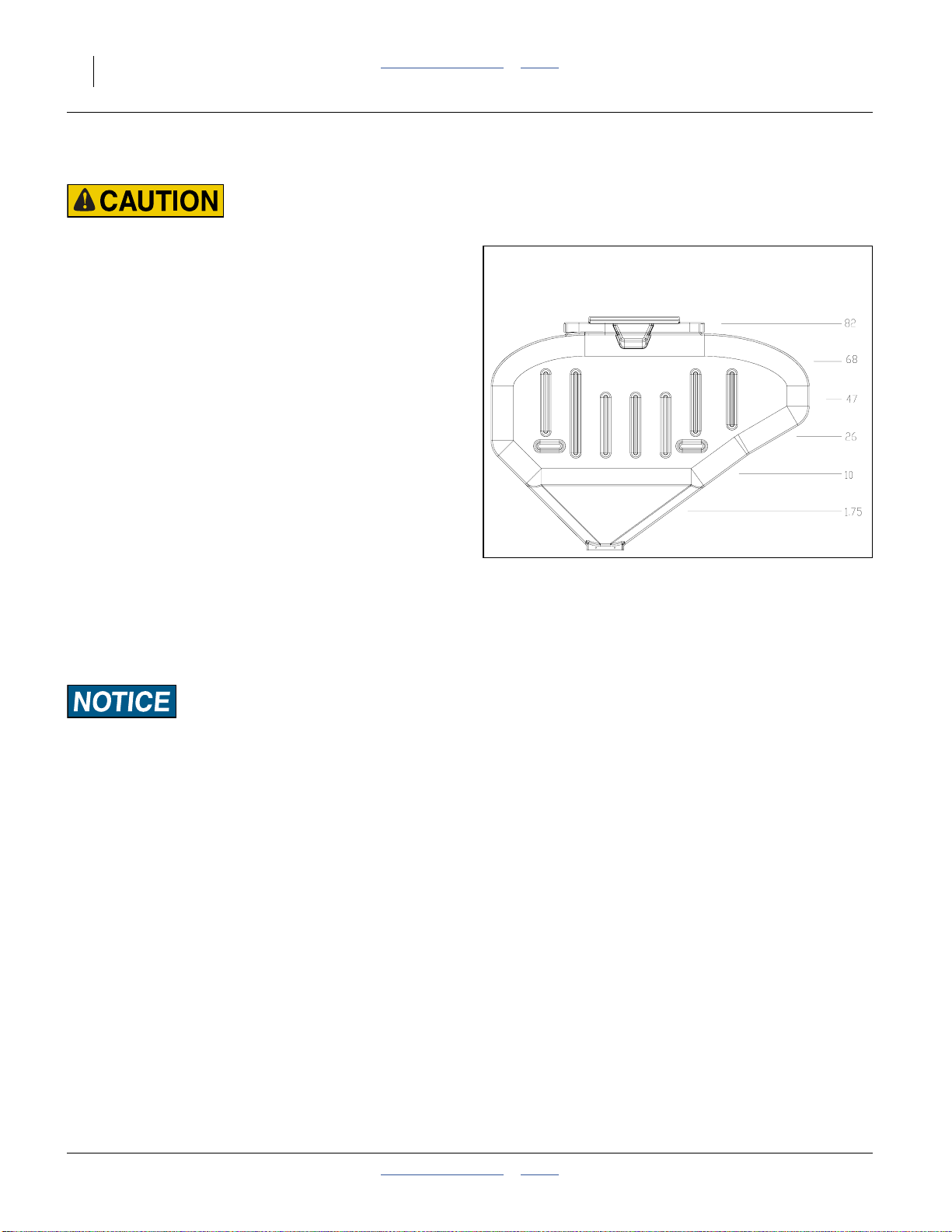
The monitor hasa level sensor below the hopperor seed
box to warn when seed box is empty. There are three to
four acres of seed in the system when the sensor first
indicates box empty.
Before the firstplanting each season, orwhen using new
meters or meter wheels for the firsttime, for thefirst time
at the start of each season, add
bottom of airbox.
1
⁄3cup graphite to
1
Figure 33
Air Box Seed Inlet
27412
Y-Tubes
Figure 34
Seed Y-Tube
Refer to Figure 34
Y-tube gates can be shut off to feed only one row for
single-row planting on 15 inch, 20 inch, or twin-row
machines. In the photograph, bothmeter tubes are open.
Note: For precise centerline alignment, it is also
advisable to offset the hitch. See “Hitching
Tractor to Planter” on page 13
22843
You can alsoshut offthe Y-tube gatesto cleanout the air
system and meters. Referto “CleaningOut AirSystem”
on page 87.
2014-09-09 Table of Contents Index 401-312M
Page 40
36 3PYP Table of Contents Index Great Plains Manufacturing, Inc.
82 bu.Hopper Operation
Tipping Hazard:
Load the 82 bu.hopper only when mounted on the cart. A full
hopper can weigh over 5000 lbs, which is above the liftingand
balance capability of most tractors and farm forklifts.
Adding Seed to 82 bu. Hopper
1. If using new meters for the first time, measure out
approximately 3 gallons of seed into a pail. Add
1
⁄3cup of lubricant. Mix and pour into air box before
mounting hopper.
2. If no seed container is present, or the previous
operation was using a bulk seed box, mount the
empty 82 bu. hopper on cart. See “Changing the
Seed Box or 82 bu. Hopper” on page 37.
3. Put tractor in Park.
4. Set FRAME hydraulic switches to OFF.
5. Turn offseed boxfan. This alsoturnsoff the Steering
(if installed).
6. Make sure walkboard is locked closed (unless it
needs to be opened for seed loading).
7. Close slide gate at base of hopper. Open lid.
8. Measure the lubricant required, and if loading seed
by bag, determine the amount of lubricant per bag.
Approximate capacity of bulk seed hopper,
in bushels, at 10 inch increments.
Figure 35
Hopper Capacities (bu.)
Note: An update kit is availablefor older 82 bu. hoppers,
providing consistent seed flow at higher fan
speeds. See page 118.
22958
Observe all safety precautions for use of loading equipment,
particularly augers.
9. Add seed, mixing in lubricant continuously or per
bag.
10. Close lid. Open slide gate.
401-312M Table of Contents Index 2014-09-09
Page 41

Great Plains Manufacturing, Inc. Table of Contents Index Operating Instructions 37
Changing the Seed Box or 82 bu. Hopper
Note: The 3PYPaccepts only the Great Plains82 bushel
hopper or bulk seed boxes that meet the Pioneer
PROBOX®specification.
a
1
Tipping Hazard:
Place or remove an 82 bushel hopper only when empty. A full
hopper can weigh over 5000 pounds, which is above the lifting
and balance capability of most tractors and farm forklifts.
1. Park the planter in an area with level ground and
sufficient room to maneuver a tractor or fork-loader.
2. Turn off the seed box fan.
3. Put the towing tractor in Park. Shut off engine.
Remove key.
4. Close the slide gate at the base of the hopper or
seed box.
Refer to Figure 36
5. Remove the walkboard lock pin .
Refer to Figure 37
6. Swing the walkboard completely open and secure
with keeper.
Refer to Figure 36
7. Remove the two pins , one back left, one right
front, used toretain the seedboxor hopper. Remove
these pins even if no container is presently mounted.
2
1
2
Figure 36
Walkboard and
Seed Box Lock Pins
2
25252
Figure 37
Walkboard Open
a. PROBOX® is a registered trademark of Pioneer Hi-Bred International, Inc.
2014-09-09 Table of Contents Index 401-312M
25253
Page 42

38 3PYP Table of Contents Index Great Plains Manufacturing, Inc.
Refer to Figure 38
8. Align the lifting forks with the slots in the rear of the
seed box or hopper. Slowly drive forward until the
forks are completely under the container.
9. Slowly lift the seed container above the bracket, and
back away from the planter.
10. Lower the container to the ground for exchange with
the next seed box.
11. If mounting a seed box, open the new seed box and
measure out approximately 3 gallons of seed into a
pail. Add
1
⁄3cup of lubricant. Mix and pour into air
box before mounting new seed box.
12. If mounting a seedbox, add lubricant to the seedbox
at this time.It may beeasier to add itwhile the boxis
still at ground level.
Plugging and Inconsistent Population Risk:
Talc+graphite lubricant is mandatory for all seed, especially
treated or inoculated seed when using precision meters.
However, DO NOT use talc with finger pickup meters. Use only
graphite lubricant with finger pickup meters. See “Seed
Figure 38
Removing/Mounting Hopper
25254
Lubricants” on page 114
Refer to Figure 39
13. Approach the hopper or seed box fromthe back (the
side with the slide gate).
Tipping Hazard:
A full seed box can weigh over 2500 pounds. Make sure your
tractor or fork lift is rated for and configured to liftthis weight.
Do not let anyone stand under or in front of the elevated seed
box.
It is possibleto liftthe hopper or seed box from any side, but it
will only function properly if the seed gate is to the rear of the
planter.
14. Slowly lift the full seed box or empty hopper, and
place it in the planter air box frame.
15. Install the box retaining pins in frame corners.
16. It may be necessary to make a one-time adjustment
to the seal on the top of the air box, to obtain full
Figure 39
Approaching Hopper
25255
contact between air box and seed box/hopper.
17. If installing an empty hopper for planting, load seed
(and lubricant).
19. Return the walkboard to the closed position and
install the latching pin.
18. Open the slide gate.
401-312M Table of Contents Index 2014-09-09
Page 43

Great Plains Manufacturing, Inc. Table of Contents Index Operating Instructions 39
Steering
(APPLIES TO ALL PLANTERS
serial numbers A1055S- through A1056S+)
Hydraulic-powered planter steering is standard on 3PYP
planters. Before using the system for transport or field
operations, calibrate the ECU
Steering controls caster position. When the hydraulic
steering system is active, the casters steer to match the
turning radius of the tractor. This prevents wheel digging
in soft soils, and minimizes field damage when backing
and turning on beds.
Refer to Figure 40
When engaged (via switch ), the system functions
automatically, and is active for all forward and reverse
movements up to 8.0 mph. Casters float during any
movement above 8.0 mph (12.9 km/h).
a
(page 151).
1
32
1
Figure 40
Steering Control Module
5
6
4
29850
Equipment Damage Risk:
All reverseplanter movements requirethe tractor for which the
planter steering is calibrated. The casters match steering only
with that tractor, and only with steering engaged. See
“Emergency Moves Without Steering” on page 154.
Equipment Damage Risk:
If the Power LED is not on and steady, do not move the
planter or make only careful forward moves. If the LED is
blinking, there is a steering malfunction, and steering is NOT
engaged. See “Steering Error Flash Codes” on page 85.
2
Figure 41
s/n A1055S- Module Rear View
7
31775
Figure 42
s/n A1056S+ Module Rear View
a. Electronic Control Unit - Steering matchrelies on sensors mountedon both planterand tractor, and calibration of the ECU(page 151).
The tractor sensor is normally dealer- installed, a topic covered in the 3PYP Pre-Delivery Manual, publication 401-312Q.
2014-09-09 Table of Contents Index 401-312M
31698
Page 44

40 3PYP Table of Contents Index Great Plains Manufacturing, Inc.
Steering Configuration Switch
This cab-mounted switch box controls both normal
operation and field calibration ofthe Steering system. It
has 4 switches and 3 indicator lamps. See page 151for
calibration details. In normal operations, only the
STEER switch and indicators and are employed.
1 2 3
Steering Control Module
Function
STEER Toggle Switch:
1
Steering System Power
LED:
2
Power / Fault
FLOAT LED:
3
Float / Caster
CALIBRATION Toggle Switch:
4
Calibration Modes
On (up): Steering enabled (casters match or float)
Off (down): Steering disabled (casters in Float)
On steady: Steering system active (casters match or float)
Blinking: Steering system fault (casters in Float)
Off: Normal operation - steering system active if STEER on
On: Casters in Float (if STEER LED is steady)
L: Caster aspect sensor (casters in Float)
C: Calibration mode off (normal transport/field mode)
Switch Positions and Indications
R: Tractor aspect sensor (casters in Float)
LEARN Button:
5
Calibration (Learn)
First press: Learn tight Right turn
Next press: Learn Straight ahead
Next press: Learn tight Left turn
LED: Calibration Off: Normal (non-Calibration) operation
6
Rotary Switch Knob
7
(ONLY APPLIES TO s/n A1056S+)
Dim: Either Calibration mode selected
Bright Flash: Button press acknowledged
5
Vertical position: Normal operation - steering system active while
planting as well as raised
Horizontal position: Used when tractor is utilizing auto-steer - steering
system floats while planting - active only when planter is raised
401-312M Table of Contents Index 2014-09-09
Page 45

Great Plains Manufacturing, Inc. Table of Contents Index Operating Instructions 41
Field Set-Up Checklist
Use the following tables to develop a final checklist for
your tractor/planter configuration. Additional or fewer
steps may be necessary depending on tractor features,
planter options and planting accessories.
Mechanical Checklist Page
Tongue height preset on 3-point 18
3-point top link adjusted (if used) 14
Planter unfolded 28
Front-to-rear level 18
Side-to-side level at gauge wheels 18
Marker tilt complete 34
Marker initial length set 20
Marker disc angle set 54
Markers folded (unless already at start of
first planting row)
Electrical Checklist Page
Verify electrical hookups solid 15
Power up monitor and observe any
diagnostic messages
With hydraulic circuits in neutral, check
switchesand indicatorlights on CLUTCH
and FRAME switch panel. Return all
switches to OFF.
If equipped with hydraulic planter drive,
verify that radar speed sensor is pointed
at ground, atan angle approximately 35°
below horizontal.
a. Refer to monitor manual.
b. Refer to sensor documentation.
Air System Checklist Page
Manifold to seed box or hopper seal Seed loaded 36
Seed lubricated 36
Tube gates turned on to correct rows 35
No air leaks (except from seed box) Hose routings - no sags, no pinches
(check wing-folded & field positions)
Clean-out doors closed at meters 87
Hoses fully connected to meters and
locked
34
a
25
b
73
Row Units Checklist Page
Preset depth handlesto 7 holesshowing
above “T”
Preset down force springs to first notch
(lightest) setting formost conditions, 2nd
notch otherwise)
Set all unit-mounted coulters to
1
⁄
in
4
shallower than opener blades.
Check coulter alignment to row 66
Check closing wheel alignment 77
Set closing wheels to first notch (light
setting)
Engage meter clutch for all desired rows 30
Check action and contact of side depth
wheels
Gauge wheel scraper gap (if installed) 70
67
61
66
77
68
Row Cleaners Checklist Page
Outer wing cleaners clear of center
section hoses (wings folded). Observe
cleaners during wing unfold to ensure
23
none catch on hoses.
Cleaner depth setting 65
Fertilizer (Option) Checklist Page
Check tractor-mounted components
Check for correct orifice plates
Check unused rows correctly closed off 57
Fill system half full withwater, and check
for leaks - run pump if possible
Check all row unit lines are connected,
free of kinks, and discharge tube/nozzles
are clear
a. Check supplier manual for tanks and pump.Check
-
fertilizer section of monitor manual.
b. Check Seed Rate manual, and manual for fertilizer
pump system.
a
b
-
-
2014-09-09 Table of Contents Index 401-312M
Page 46

42 3PYP Table of Contents Index Great Plains Manufacturing, Inc.
Hydraulic System Checklist Page
Check hydraulic reservoir full Inspect connections for leaks Perform a raise and lower operation 22
Check fan speed and airflow direction
a
If equipped, set CLUTCH Master switch
off, and check hydraulic planter drive
30
rotation
Ensure all FRAME switches are OFF
except Marker Fold
a. Operate fan briefly and observe rotor blades
spinning toward exit port. Check rpm on seed
monitor.
25
Gauge Wheel Planter Drive Checklist Page
Check gauge wheel inflation and tread
condition
Set range, transmission and upper drive
sprockets for desired seed rate
Check all chains for lubrication and
proper slack
Lubricate slider joints on drive shafts 107
Check clutch operation 30
125
47
107
Hydraulic Planter Drive Checklist Page
Check chain lubrication and slack 107
Input initial values for desired seed rate
Pre-run system using seed monitor
Calibration mode to verify hydraulic
a
b
action
Lubricate slider joints on drive shafts 107
Check clutch operation 30
a. Refer to seed monitor manual and Seed Rate
manual.
b. Refer to seed monitor manual.
Meters Checklist Page
Correct meters for seed
Correct wheels for seed *
Correct fingers for seed *
Close clean-out doors 87
Corn?
Check timing of meters for twin-row
Check chain tension
Check meter assemblies secured 73
Engage drive couplers 73
Add lubricant to seed if not already done 36
a
*
a. Refer to Seed Rate manual.
401-312M Table of Contents Index 2014-09-09
Page 47

Great Plains Manufacturing, Inc. Table of Contents Index Operating Instructions 43
Field Operation
Perform all steps in “Pre-Start Checklist” on page 21
and “Field Set-Up Checklist” on page 41.
First Pass Operation Page
Fold up marker. 34
Raise planter and line upat start offirst
planting row
Set tool bar height to 26 inches. 18
Set tractor 3-point hitch to “depth
control” operation (and not load control)
If tractor hitch is set for load control,
planting depth will be uneven.
Unfold marker on next-row side. 33
Turn on seed fan. Adjust hydraulic flow
for 3800 rpm.
If planter is equipped with hydraulic
drive, engage drive via seed monitor.
Refer to seed monitor manual.
If planter hasa fertilizer system, turn on
the pump. Refer to pump manual.
On CLUTCH switch control panel, set
all switches to ON.
Pull forward, lower planter, and begin
planting for a short distance.
Stop. Assess:
planting depth
seed spacing
press wheel operation
Make necessary adjustments 46
Turns
1. Stop at completion of row
2. Fold marker 34
3. Raise planter 22
4. Make turn
5. Lower planter 22
6. Unfold marker on next-row side. 33
7. Begin planting.
22
35
30
Page
Suspending Planting
1. Stop tractor
2. Shut off seed fan 35
3. Shut off fertilizer pump
4. Raise planter 22
5. Shut off hydraulic drive (if equipped)
6. Fold Marker 34
7. Tilt Marker down 34
Ending Planting
1. Suspend operations as above, then
2. Install lift assist locks 26
3. Steering OFF 39
4. Lights ON
5. Transport 26
Page
Page
Planting
When all checklist items are complete, a planting pass
normally consists of a few simple steps:
Pass 1 (with marker extended)
1. Lower planter (Hitch then Lift)
2. Drive forward
3. Scan monitors and controls. Check for errors, alerts
and out-of-limits events. Check planting rate reports.
4. At end of pass, stop.
5. Raise planter (Lift then Hitch)
6. Extend/retract marker as needed for next pass
7. Turn
Subsequent Passes
8. Resume at step 1.
When reloading seed and fertilizer, check consumption
against anticipated use to that point.
Checking Planting Rate
Although your seed monitor reports useful full pass
results, cautious practice includesmanually checking the
seed rate early in the first pass.
2014-09-09 Table of Contents Index 401-312M
The Seed Rate Chart book for this planter (manual part
number 401-312B) contains sampling instructions.
Page 48

44 3PYP Table of Contents Index Great Plains Manufacturing, Inc.
Short-Term Parking
1. Fold markers and tilt them down. See “Folding The
Markers” on page 34
2. Choose a location with level firm ground. Do not
unhitch on a steep slope.
3. Unfold the planter. If there is ample space, Great
Plains recommends parking the planter unfolded.
This allows easiest access for routine maintenance,
particularly on the folding mechanism. Do not insert
wing lock pins.
Refer to Figure 43 and Figure 44
2
1
3
Falling Object Hazard:
Do not stand in front of stand while swinging it down. If you
lose control of the motion, the stand can seriously injure you.
4. Remove pin holding each parking stand up.
Swing stands down. They may not be fully vertical at
this point.
5. Fully raise planter.
6. The load on the parking stands is as much as
5700 pounds each (or 116 psi). If the ground is soft
or uncertain, place boards or concrete pads under
the parking stand locations.
7. Insert pin in the lower hole , locking the stand in
the parking position.
8. Remove pin and extend inner parking leg to the
ground.
9. Slowly raise the leg until the hole in the outer leg
aligns with a hole in the inner leg. Re-insert pin .
10. Install lift assist lock if not already present.
11. Lower planter until hitch is not resting on tractor
3-point.
12. Disconnect hydraulic lines. Secure them sothat they
do not touch the ground.
13. Disconnect electrical cables, capping where
provisioned.
1 2
1 3
4 5
4
Figure 43
Parking Stand Raised
Figure 44
Raising Parking Stand
25241
3
4
5
25240
401-312M Table of Contents Index 2014-09-09
Page 49

Great Plains Manufacturing, Inc. Table of Contents Index Operating Instructions 45
Long-Term Storage
14. Park the 3PYP indoors if possible, per the steps
above. Great Plains recommends parking/storing in
the raised position, unfolded, on extended parking
stands and with lift-assist cylinder locks in place.
15. If no hopper or seed box is mounted, cap the air box.
16. If empty seed box or hopper is mounted, close the
seed gate and the lid.
17. If partially-loaded seed box or hopper is mounted,
close seed gate, and remove seedbox. Store planter
only without seed.
18. Open air box clean-out door. Clean out residual
seed.
19. Dismount meters. Open meter clean-outs. Invert
meters and shake out loose seed.
20. Clean out air delivery system. Run fan with meters
disconnected.
21. Tie or tape a small plastic bag over ends of all seed
delivery tubes to prevent insects from entering or
nesting.
Figure 45
Planter Parked
25256
If meters are dismounted, tie or tape a small plastic
bag over ends of all air tubes, and block openings
where meters attach to row units.
22. Apply grease to exposed cylinder rods to prevent
rust.
23. Flush fertilizer lines (if present).
24. Empty and clean fertilizer filter.
25. Plug or cap fertilizer line to tractor.
26. Clean planter of mud, dirt, excess oil and grease.
2014-09-09 Table of Contents Index 401-312M
Page 50

46 3PYP Table of Contents Index Great Plains Manufacturing, Inc.
Adjustments
To get full performance from your 3PYP, you need an
understanding of all component operations, and many
provide adjustments for optimal field results. Some of
these have already been covered earlier in this manual.
Even if your planting conditions rarely change, some of
these items need periodic adjustment due to normal
wear.
Adjustment Page The Adjustment Affects
Frame height 18 Planting depth
Frame level 18 Planting consistency
Height Switch Adjustment 55 Correct off/on state of meter drive
Wing Leveling 157 Planting consistency
Gauge Wheel Tension 51 Planting depth; reliable row unit operation
Gauge Wheel Sprocket Selection (ground drive) 47 Reliable row unit operation
Hydraulic Drive (option) Adjustments - Refer to 3PYP Seed Rate manual
Gauge Wheel Sprocket Selection (ground drive) - Refer to 3PYP Seed Rate manual
Marker Extension 20 Intended row spacing
Marker Chain Length Adjustment 88 Visibility of centerline mark
Dual Marker Speed Adjustment 89 Reliable marker operation
Fan Adjustments 56 Consistent seed flow to meters
Fertilizer Setup (option) 57 Seed germination and growth
Fertilizer Orifices (option) - Refer to 3PYP Seed Rate manual
Hydraulic Down Pressure 60 Consistent planting depth
25 Series Row Units 60
Row Unit Lock-Up 64 Single/twin-row operation
Row Unit Down Pressure 61 Planting depth
Unit-Mount Cleaner Adjustments (Option) 65 Row preparation
Coulter Adjustments (Option) 66 Row pre-groove depth
Row-Unit Opener Adjustments 67 Seed groove depth and width
Adjusting Depth Wheel Scrapers 70 Consistent seed groove depth
Seed Meter Setup and Adjustment 70 Consistent seed population
Finger Meter Indexing - Refer to 3PYP Seed Rate manual
Seed Firmer Adjustments (Option) 76 Seed-soil contact
Press Wheel Adjustment 77 Effective soil coverage
Monitor Adjustments - Refer to Seed Monitor manual
Older Planters
Row mode spacer 158 Intended row-group spacing
Hydraulic Down Pressure 159 Consistent planting depth
401-312M Table of Contents Index 2014-09-09
Page 51

Great Plains Manufacturing, Inc. Table of Contents Index Adjustments 47
Setting Seed Rate
The procedure for setting seed rate dependson whether
the planter has ground (contact) drive or hydraulic drive.
Rate setting details are found in other manuals. Some
general information is found in this manual.
Regardless of howrate is set,rate is preciselymeasured
by the seed monitor, for most seed types.
Indexing
In twin-row operations with finger pickup meters,
seed-to-seed spacing between pairs of a “row” can be
controlled by sprocket indexing (see page 76).
Gauge Wheel Sprocket Selection
On 3PYPs without hydraulic drive, the row units are
driven by the gauge wheels, in ground drive.
Refer to Figure 46
The ground drive assembly has three chains that are
user adjustable:
1. Range
2 of 6 sprockets, stored on shafts
both ends may adjust
2. Transmission
2 of 10 sprockets, stored on vertical spindle
both ends may adjust
3. Upper drive
1 of 2 sprockets, selected by spacer
only one end adjusts
For a specific row-spacing, meter and seed, the starting
sprocket settings for all three chains are found in the
Seed Rate Chart book for this planter (manual part
number 401-312B).
Fine adjustment to planting rate is made by the
Transmission chain .
Sprocket pairings are identified in the Charts both by
sprocketsize andby which sprocketis mounted onwhich
shaft.
Sprockets are sized by tooth count, stamped on the
sprocket.The same shaft can be both a driving and
driven shaft depending on the required combinations.
The DRIVINGshaft on any chainis the one closer to the
gauge wheel (lower in the assembly).
The DRIVEN shaft on any chain is the one further from
the gauge wheel (higher in the assembly).
1
Seed
Rate
Control
Coarse
Fine
Planter Drive Type
Contact Hydraulic
Range Sprockets
(see page 48 and
Seed Rate Manual)
Upper, Transmission
Drive Sprockets
(see page 49 and
Seed Rate Manual)
Console Data Entry
(see Monitor Manual)
3
1
Figure 46
Ground Drive Chains
Seed Monitor
2
25259
2014-09-09 Table of Contents Index 401-312M
Page 52

48 3PYP Table of Contents Index Great Plains Manufacturing, Inc.
For All Ground Drive Adjustments
Steps:
1. Raise the planter and install lift-assist cylinder locks.
2. Rotate each gauge wheel. Check that seed meters,
seed tubes and drives are working properly and are
clear of debris and obstructions.
3. Check tire pressure, per “Tire Inflation Chart” on
page 125.
Drive Range Sprockets
1. Obtain the sprocket pairing from the Seed Rate
Chart.
2. Loosen the bolt on the forward idler , and slide the
idler to the bottom of its track.
3. Remove the lynch pins from both the driving , and
driven shafts.
4. Remove the four alternate sprockets, and set them
on the tool bar.
5. Remove the chain and hang it behind a lynch pin on
the transmission.
6. Exchange the existing low range sprockets for those
called out in the Seed Rate Chart.
3
1
2
The 3PYP must be unfolded,and the tractoror planter parked,
before making any of these adjustments.
Equipment Damage/Misapplication Risks:
Any setup and adjustments must be made identically on each
of the two gauge wheel drives. If there are any differences,
there will be excess clutch wear, and unpredictable seed rate
results.
3
Driven
1
Equipment Damage/Misapplication Risks:
Make sure the correct sprockets are mounted on the driving or
driven shafts as called for by the Charts.
7. Slide the idler up, and tighten its bolt, allowing
1
⁄4inch slack in the longest chain span.
8. Store the four alternate sprockets on the shafts and
re-pin.
1
2
Figure 47
Lower Range Sprockets
Driving
25260
401-312M Table of Contents Index 2014-09-09
Page 53

Great Plains Manufacturing, Inc. Table of Contents Index Adjustments 49
Upper Drive Sprocket
1. Obtain the driven sprocket selection from the Seed
Rate Chart. Make sure your configuration actually
needs to be changed.
2. Loosen the bolt on the forward idler , and slide the
idler to the bottom of its track.
3. Remove split plastic spacer . It will be to the left of
the smaller (18 tooth)sprocket if the18T was in use,
and to theright ofthe larger (36 tooth) sprocket if the
36T was in use.
4. Move the spacer (part number 120-337S) to the
other side of the sprocket pair, sliding the sprocket
pair left or right to make room.
c
5. Lift the chain off the sprocket formerly in use, and
move it to the sprocket to be used.
6. Slide the idler up, and tighten its bolt, allowing
1
⁄4inch slack in the longest chain span.
Transmission Sprockets
1. Obtain the initial sprocket pairingfrom the Seed Rate
Chart.
2. Loosen the bolt on the forward idler , and slide the
idler to the bottom of its track.
3. Remove the lynch pins from both the driving , and
driven shafts.
4. Remove the chain and hang it behind a lynch pin on
the low range.
5. As needed, exchange the existing sprocket pair for
the new pair, using alternate sprockets from the
vertical storage spindle .
3
a
b
4
a
1
2
Driven
c
a
b
Driving
Figure 48
Upper Drive Sprocket
4
25261
Driven
3
2
1
Equipment Damage/Misapplication Risks:
Make sure the correct sprockets are mounted on the driving or
driven shafts as called for by the Charts.
6. Slide the idler up, and tighten its bolt, allowing
1
⁄4inch slack in the longest chain span.
7. Store the removed and any loose sprockets on the
spindle shaft and re-pin it. Make sure all eight
alternative sprockets are accounted for.
2014-09-09 Table of Contents Index 401-312M
1
Transmission Sprockets
Driving
Figure 49
25262
Page 54

50 3PYP Table of Contents Index Great Plains Manufacturing, Inc.
Transmission Adjustments
For singulating and finger pickup meters, rate
adjustments should never be necessary. If the seed
spacing is not correct, it is likely that there is a planter
configuration error or malfunction. Find and correct the
problem. Do not attempt to compensate for it by
adjusting the target population rate.
For volumetric seeds, after checking initial planting rate,
per the Seed Rate manual, it may be necessary to make
changes to the transmission sprocket configuration.
If the error is small, a few percent, choose a slightly
higher or lower target population from the Seed Rate
chart, and install new sprockets for that rate.
If the error is large, it is likely that there is a planter
configuration error or malfunction. Find and correct the
problem. Do not attempt to compensate for it by
adjusting the target population rate.
Gauge Wheel Adjustments
The gauge wheels, which may also be contact drive
wheels, serve three functions:
1. Regardless of meter drive type, the gauge wheels
each establish the heights of their respective wings.
A spring-loaded yoke assembly provides some
flexibility over rocks and uneven ground. See
“Gauge Wheel Tension” on page 51 to set this
spring.
2. In ground-drive (contact-drive), the gauge wheels
mutually contribute drive power for the row unit
mechanisms. See “Gauge Wheel Sprocket
Selection” on page 47.
3. In ground-drive, the gauge wheels control the
planting rate at the meters, via three sprocket setup
positions. See “Gauge Wheel Sprocket Selection”
on page 47.
Figure 50
Gauge Wheel - Ground Drive
25257
Figure 51
25434
Gauge Wheel - Hydraulic Drive
401-312M Table of Contents Index 2014-09-09
Page 55

Great Plains Manufacturing, Inc. Table of Contents Index Adjustments 51
Gauge Wheel Tension
Refer to Figure 52
Beforeperforming this step, the3PYP centersection and
wings must be level and aligned, and the tool bar height
must be set to 26 inches. If these steps have not been
performed, “Frame Height and Leveling” on page 18
and “Wing Leveling” on page 157.
As the gauge wheeltire wears, this adjustment may need
periodic attention.
The planter must be on firm, level ground for this step
(which may be performed when the planter leveling is
done). The planter must be unfolded.
1. Raise the planter so that the gauge wheels are just
off the ground.
2. Loosen the nut above the yoke block .
1 2
3. Raise or lower the planterso that the base ofthe tool
bar is 26 inches from the ground.
4. Using an open-end or adjustable wrench at the
integral hex nut of the adjustment link , rotate
the link until the spring is just touching the yoke
block , with neither gap nor compression.
4
2
5. Tighten the top nut .
3 4
1
4
3
Figure 52
Adjusting Gauge Wheel Tension
1
2
6
5
25258
Contact Drive Adjustments
When planting, if the monitor indicates under-seeding,
check for slippage of the gauge wheels. If they are
slipping:
1. Raise the planter so that the gauge wheels are just
off the ground.
2. Loosen the nut above the yoke block .
3. Using an open-end or adjustable wrench at the
integral hex nut of the adjustment link , rotate
the link to adjust the gauge wheel tension. Using
4
the base of the link flange , and the pivot grease
zerk as a reference, increase this distance to
5 6
increase down-force on the wheel.
4. Tighten the top nut .
1 2
3 4
4
1
2014-09-09 Table of Contents Index 401-312M
Page 56
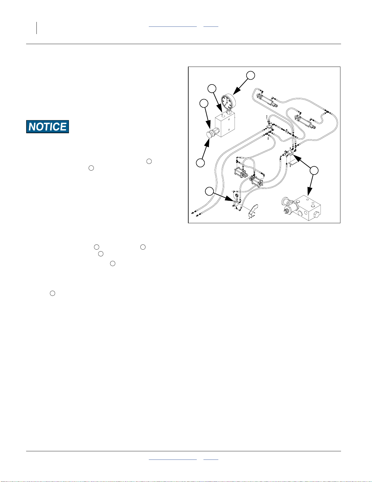
52 3PYP Table of Contents Index Great Plains Manufacturing, Inc.
Hydraulic Down Pressure
Refer to Figure 53
If the desired opener depth cannot be consistently
achieved using spring adjustment (page 62), or the
gauge wheel is slippingat theforce required,the optional
hydraulic down pressure may remedy the problem. It
uses two cylinders to transfer more weight to the wings.
Equipment Damage Risk:
The current hydraulic down pressure option is compatible only
with “closed center” tractor hydraulics.
Before making depth adjustments with valve , make
sure the system (valve ) has been calibrated. See
“Hydraulic Down Pressure Calibration” on page 159.
To adjust hydraulic down pressure:
1. Set the mechanical (cam spring) down pressure to
notch 3. See “Row Unit Down Pressure” on
page 61.
2. The remote lever must be LOCKED OPEN in this
position to provide constant pressure/flow to the
openers.
3. With the tractor hydraulic lever locked forward,
release the lock disk , turn the knob on the
pressure control valve .
4. Watch the pressure gauge and set the desired
pressure. Clockwise increases the pressure and
counterclockwise decreases pressure.
5. Once the pressure is set, lock the knob with the lock
2
disk .
Note: Refer to“Hydraulic Down Pressure Calibration”
on page 159 toknow what to expect the planter to
do as hydraulics are cycled.
The recommended pressure range for planting is
between 400 psi and 600 psi.
The opener pressure setting controls the soil firming
pressure on the press wheel as well as the disk
penetrating force. DO NOT use more opener down
pressure than necessary to obtain the desired opener
penetration and to maintain the proper firming action
over the seed. Excessive opener force will lead to
excessive wear and damage of the opener components.
c
2 3
1
4
1
4
1
2
3
c
1
Figure 53: s/n A1025S+
Hydraulic Down Pressure Valves
John Deere 8000 Series tractors:
Set timer to continuous. Push lever forward until detent
clicks.
Case IH®Magnum™ tractors:
Lock lever forward in detent position. You may need to
turn up detent pressure to its maximum setting. Do not
tie hydraulic lever past detent position with a strap. See
your tractor dealer for hydraulic-system details.
Other tractors:
Lock lever forward in detent position. You may need to
turn up detentpressure tomaximum or usea mechanical
detent holder to hold lever forward. See your tractor
dealer for providing constant flow to openers.
29194
401-312M Table of Contents Index 2014-09-09
Page 57

Great Plains Manufacturing, Inc. Table of Contents Index Adjustments 53
Cart Weight Transfer
On s/n A1025S+ planters, some of the cart weight can
be transferred to the mainframe by retraction of the
lift-assist cylinders, with a weight-transfer pin in place.
This operating mode is compatible with wing-lock,
wing-flex and hydraulic down-pressure planters.
1. Disconnect the 3-point top link.
Refer to Figure 54
2. Install the lift-assist weight-transfer pins . The pins
are stored in a plate behind the cart parallel arm
pivot weldment. Install them in the large holes at the
bottom of the rod-endlug inthe frame-to-cart parallel
arms.
3. Remove the lift-assist shear bolts from the small
2
holes below the lift-assist rod-end lug upper pivot
pins. Store the bolts in the plates behind the cart
parallel arm pivot weldments.
4. Fully retract the lift-assist cylinders when lowering
the planter in the field.
1
Figure 54
Weight Transfer Pin
2
1
29201
Priority Flow Hydraulic Systems
On some tractors with load-sensing hydraulics, the
tractor remote circuit #1 is capable of taking nearly
100 percent of available hydraulic flow. Operating the
openers or markers on circuit #1 will starve the other
circuit, making one function inoperable.
To operate markers and constant opener down pressure
at the same time, connect the lift assist to circuit #2 and
the markers to circuit #3.
Note: On some tractors with very positive remote
hydraulicchecks,aslightincrease inthereading on
the pressure gauges may occur after the tractor
remote lever isreturned to neutral. This is caused
byback pressure on theopener cylindersand may
beignored. The NET OPERATINGPRESSUREon
the opener cylinders is maintainedat the pressure
you selected while the tractor remote lever was
held forward–not at the “apparently increased”
pressure. Reactivating the tractor lever forward
confirms this.
2014-09-09 Table of Contents Index 401-312M
Page 58

54 3PYP Table of Contents Index Great Plains Manufacturing, Inc.
Marker Adjustments
There are five adjustments for markers:
• Disk Angle
Even if your row spacing rarely changes, you may
need to adjust disk angle for soil conditions and
planting speed.
• Marker Width
Once set for a specific row spacing, this only needs
periodic checking to ensure the clamp is secure.
See page 20.
• Shear Bolt Replacement
If a marker hangs up on an obstruction, a bolt at the
fold is designed to fail. Positions are provided nearby
for storage of replacement shear bolts. See page 88.
• Chain Length
Depending on marker width, you may want to adjust
the chain length to ensure the markers are off the
ground when the planter is raised. See page 88.
• Marker Speed
Once initially set by your dealer, this rarely needs
modification. See page 89.
Crushing and Sharp Object Hazards:
You may be injured if hit by a folding or unfolding marker.
Markers may fall quickly and unexpectedly if the hydraulics
fail. Never allow anyone near the planter when folding or
unfolding the markers.
Marker Disk Adjustment
Sharp Object Hazard:
Marker disks may be sharp. Use caution when making
adjustments in this area.
Refer to Figure 55
To change angleof cut,and thewidth ofthe mark,loosen
1
⁄2inch bolts holding disk assembly.
For a wider mark (W), increase the angle of the marker
with respect to the tube . For a narrower mark (N),
reduce the angle.
Tighten bolts .
Note: The direction of travel(T) tendsto drive the disk
angle to Wide. If bolts are not tight enough, or
loosen over time,the diskwill slipinto theWide
mark configuration.
2
1
2
W
N
2
Figure 55
Marker Disk Angle
1
T
11757
401-312M Table of Contents Index 2014-09-09
Page 59

Great Plains Manufacturing, Inc. Table of Contents Index Adjustments 55
Height Switch Adjustment
Refer to Figure 56
The 3PYP includes a sensing switch that signals the
seed monitor (and activates the meter drives), when the
planter is lowered for planting.
Although factory-preset for typical planting conditions,
Great Plains recommends adjusting this switch for your
exact field conditions and planting depth. Check the
switch seasonally thereafter, or when plantingconditions
change. Also perform this adjustment if the switch is
replaced or dislodged.
The switch is located on theparallel arms connecting the
planter mainframe to the air cart.
Refer to Figure 57
1. Lower the planter to the height at which seed
delivery is to begin.
2. Loosen bolts holding switch bracket to frame.
3. Movebracket and switch upor downso switch toggle
4 5
arm makes contact with upper parallel arm .
4. Move switch/bracket down
Note: It may be necessary to loosen the screws
holding the switch to the bracket and rotate the
switch slightly on the bracket.
Note: If theswitchisevercompletely removed,be sure to
replace it with the cable exit atthe bottom.If the
cableis atthetop,switchoperationisreversed,and
moisture will accumulate in the switch, causing
eventualswitch failure.
2 3
1
1
⁄4inch. Tighten bolts.
6
1
Figure 56
Height Switch Location
5
2
Figure 57
Height Switch Adjustments
6
29193
4
1
3
25442
2014-09-09 Table of Contents Index 401-312M
Page 60

56 3PYP Table of Contents Index Great Plains Manufacturing, Inc.
Fan Adjustments
Recommended fan butterfly valve setting is 0°.
Recommended fan speed depends on planter
configuration:
3800 rpm 2008+ planters using 2008+ 82 bu. hoppers
(or older hoppers with the vent line update)
3500 rpm 2006- planters, or any planter using bulkseed
boxes or unvented hoppers
Adjust the basicfan rate withthe tractorhydraulicsystem
and fan rpm display on seed monitor. Do not run the fan
over 4500 rpm or under 3000 rpm.
Fans operating at too high a speed create too much air
flow causing seed to plug up the meter box. Fans
operating too slowly do not create enough air flow to
push the seed to the meters, causing the seed tube to
plug. If air system does not operate suitably with fan
speeds between 3000-4500 rpm, refer to the
troubleshooting chart, and then adjust the fan butterfly
valve.
The butterfly valve may be helpful if your tractor can
maintain a high, but irregular fan rpm. Set the rpm to
above 3500 rpm with the valve completely open (0°).
Adjust the valve angle in the 20-30° range until you
achieve the desired seed flow consistency.
Figure 58
Fan Butterfly Valve
25267
401-312M Table of Contents Index 2014-09-09
Page 61

Great Plains Manufacturing, Inc. Table of Contents Index Adjustments 57
Fertilizer Setup
Agricultural Chemical Hazard:
Some chemicals will cause serious burns, lung damage, and
death. Avoid contact with skin or eyes. Wear proper protective
equipment as required by chemical manufacturer. Avoid
prolonged breathing of chemical fumes. Wear respirator as
required by chemical manufacturer. Seek medical assistance
immediately if accident occurs. Know what to do in case of
accident.
A fertilizer distribution system is optional on the 3PYP.
The Great Plains provisioned components include:
• the lines to the row units (connected to Keeton® seed
firmers if present),
• orifice fittings for each row
• distribution lines
• manifold
• pressure gauge
• relief valve
• inlet (1 inch female NPT) from pump systemon tractor
(Refer to Figure 60 on page 59)
If installed, there are five points of fertilizer setup and/or
adjustment:
1. Pump drive connection and valves
These are separately provisioned tractor-mounted
components, and are not described in this manual.
2. Strainer setup
This is a separately provisioned tractor-mounted
component, but the mesh screen size must be
compatible with the orifice plates in the distribution
system. See this page and “Fertilizer Orifice
Plates” on page 58.
3. Relief valve setting
See “Fertilizer Relief Valve” on page 59
4. Pump drive rate
This is a separately provisioned tractor-mounted
capability. Rate setting is described in this manual,
but system operation is not.
5. Row orifice setup
See “Fertilizer Orifice Plates” on page 58
Great Plains recommends checking with your local
agronomist as soil conditionsvary. Soilconditions inyour
area may needless or more fertilizerthan represented in
these charts. Do not exceed 12 gallons per acre in any
case.
The liquid fertilizer system is designed to operate
(ideally) between 15 and 40 psi, but in no case more
than 85 psi. Several system elements affect system
pressure, and need initial setup, periodic maintenance,
and adjustment when changing seed rates.
Liquid Fertilizer Strainer
A strainer is normally supplied with the fertilizer pump
option and is plumbed between the tank(s) and the
pump.
The strainer will have been delivered with a mesh
screen. You need to check that it is an appropriate size
for the orifice plates you plan to use.
The standard orifice plates for the 3PYP are size 48.
If changing screen sizes, keep in mind the following:
• Generally, select a mesh screen the same or slightly
smaller than the orifice size.
• A substantially smaller mesh (e.g. 100) will reduce
manifold orifice plates plugging so often, but the
strainer screen will have to be cleaned more often.
• A much larger mesh (e.g. 50 or 30) will pass more
material but should only be considered when using
large manifold orifice plates.
• A plugged or partially plugged screen will starve the
pump and will result in a reduced application rate.
2014-09-09 Table of Contents Index 401-312M
Page 62

58 3PYP Table of Contents Index Great Plains Manufacturing, Inc.
Fertilizer Orifice Plates
Refer to Figure 59
To install,insert theplate inside the gasket supplied
with the nozzle . Insert the gasketed plate with the
legend side facing out the nozzle outlet (typically up).
In general, the orifice needs to be small enough to
create enough pressure in the manifold to operate the
check valves in the boomclamps, but notso muchthat
the system dumps product at the boom relief valve.
The recommend operating pressure is: 15 to 40 psi
Using an orifice size too large can result in unequal flow
at rows, intermittent flow, and flow stoppage at rows
where pressure fallsbelow the8 psirequired to open the
clamp check valve. Using a size too small can cause
excess back-pressure resulting in material dumping at
the boom relief valve.
Use the same size at all active rows.
Exception: If one or two outside “zone coulter”
3
4
applicators re-trace the same furrow on
opposing passes, you can halve the rate at
these rows (only) by using a smaller orifice
plate (see table at right)
1 2
1
5
4
Figure 59
Fertilizer Orifice Plate
1
3
2
29984
Alternate orifice plates are listed under “Fertilizer
Orifice Plates” on page 118.
The Seed Rate Chart book for this planter (manual part
number 401-312B) contains a table of orifice sizes in
gallons per acre.
Fertilizer Row Shut-Off
Refer to Figure 59
Unused drop lines may be shut off by replacing the
nozzle with a Great Plains 832-042C cap . Twin row
boom systems separately include caps for half the rows.
When installing a cap:
• It is not necessary to remove the gasketedorifice plate
• Use atie wrap orother lineto securethe loose nozzle
• Adjust pump and/or orifice plates for new rate and row
Material Loss Risk:
Do not apply materials without first reviewing setup. Shutting
off rowsdoes not change the application rate. Unless the pump
is reset, it operates at the prior rate, doubling the flow at each
nozzle. This can result in excess pressure, and material loss at
the relief valve.
3 5
from inside the clamp. The capincludes itsown gasket
that seals at the end of the clamp port.
and drop line tubing to the boom.
spacing.
Note: Replacement nozzles include gaskets.
Gaskets may also be orderedseparately asGreat
Plains part number CP18999-EPR.
Agricultural Chemical Hazard:
Wear protective gloves when changing orifice plates and
strainer screens. Consult material manufacturer or supplier
documents for proper handling and steps to take if skincontact
occurs.
Orifice Part Port Port
Size Number Diameter Area
20 832-052C 0.020 in 0.20 mm²
28* 832-056C 0.028 in
34* 832-053C 0.034 in 0.59 mm²
48* 832-054C 0.048 in 1.17 mm²
59 832-057C 0.059 in
80 832-055C 0.080 in 3.24 mm²
98 832-059C 0.098 in 4.87 mm²
Check your accessories before ordering.
0.40 mm²
1.76 mm²
29993* Sizes standard in many fertilizer bundles.
401-312M Table of Contents Index 2014-09-09
Page 63

Great Plains Manufacturing, Inc. Table of Contents Index Adjustments 59
Fertilizer Relief Valve
Refer to Figure 60
A relief valve and pressure gauge are mounted at
the fertilizer inlet connection point to the tractor, and
provides the fertilizer feed to the manifold (manifold
not shown). The relief valve protects the manifold, lines
and fittings from excessive pressure. Any product that
dumps over the relief valve willdischarge from the dump
➄ in relative safety, rather than appearing
line
unpredictably at some random point in the system.
To set relief valve:
1. Unlock plastic jam nut from relief valve knob.
2. Unscrew knob clockwise (looking down) until it
loses contact with internal spring.
3. Screw knob counterclockwise two turns.
Start at this setting.
4. Observe manifold gauge and watch for relief valve
dump line discharge while operating in the field.
5. If valve is dumping product and gauge reads under
85 psi, stop tractor and turn knob clockwise
1
⁄4turn. Continue operating at normal field speed.
Repeat this step as needed until no product is
discharged from relief valve dump line .
6. If thepressure gaugereads above 85 psi, change to
a larger orifice. Go to step 2 and repeat.
1 2
3
4
3
7
7
2
5
2
3
4
1
5
6
7
7
Figure 60
5
Fertilizer Relief Valve
25164
Ground Drive Fertilizer Pump
Planters ordered without a fertilizer pump system, or
which have an oldershaft-driven pumpmay be upgraded
to ground drive CDS-John Blue® piston pump:
Option Packages
3PYP JB GND DRV PSITON PMP ASM 407-422A
For operations, see the Seed Rate manual.
Part
Number
28416
2014-09-09 Table of Contents Index 401-312M
Page 64

60 3PYP Table of Contents Index Great Plains Manufacturing, Inc.
25 Series Row Units
Refer to Figure 61 (which depicts a row unit fully
populated with alloptional accessoriessupportedforuse
with the 3PYP planter)
Note: All row-unit components are unit-mounted.
The 3PYP does not support frame-mounted
components other than the row unit itself.
Fromfront to back,a Great Plains25 Series row unit can
include the following capabilities (some optional):
0
Row Unit Lock-Up: (standard, pin not shown)
In twin-row configurations, the rear row unit may be
locked up to reduce wear in single-row operations,
using a pin stored in a hole in the upper forward
mount, which is transferred to a hole below the rear
end of the lower parallel arms. See “Row Unit
Lock-Up” on page 64
1
Parallel arms: standard
Each row unit ismounted on the planter with parallel
arms which allow each row unit to independently
move up and down while staying horizontal. See
“Row Unit Down Pressure” on page 61
0
0
2
3
1
6
7
4
Figure 61
25 Series Row Unit
8
5
9
18287
25193
2
Row cleaners: optional
Row cleaners clear trash from the row. Twin-row
planters support single-arm cleaners. Single-row
planters supportsingle- or double-arm cleaners. See
“Unit-Mount Cleaner Adjustments” on page 65
3
Coulter: optional, choice of wheels
Coulters cut any remaining trash, and create a
pre-groove for light no-till planting. The down force
needed to cut and widen the coulter groove is
supplied by the row unit. The depth relative to the
opener is setby achoice ofhub mounting holes.See
“Coulter Adjustments” on page 66
4
Openers: standard, 2 per row unit
Openers double disks widen the coulter groove,
creating the seed bed. Setup controls depth, width
and sidewall angle. See “Row-Unit Opener
Adjustments” on page 67
5
The depth gauge wheels also accept an optional
scraper.See “Adjusting DepthWheel Scrapers”on
page 70
6
Seed meter: required, choice of models/features
Meters deliver singulated or volumetric seed. See
“Seed Meter Setup and Adjustment” on page 70
7
Seed delivery tube: standard (not shown)
No adjustments are necessary.
8
Seed firmer (optional):
Keeton® seed firmer (shown mounted)
Improves seed-soil contact, and provides a stable
arm for a low-rate liquid fertilizer delivery tube. See
“Keeton® Seed Firmer Adjustment” on page 76
Seed-Lok® firming wheel (shown in inset)
Improves seed-soil contact. See “Seed-Lok® Seed
Firmer Lock-Up” on page 76
9
Press wheels: standard (choice of types)
These close the seed trench. See “Press Wheel
Adjustment” on page 77
Certain Machine Damage:
Do not back up with row units in the ground. To do so will
cause severe damage and row unit plugging.
401-312M Table of Contents Index 2014-09-09
Page 65
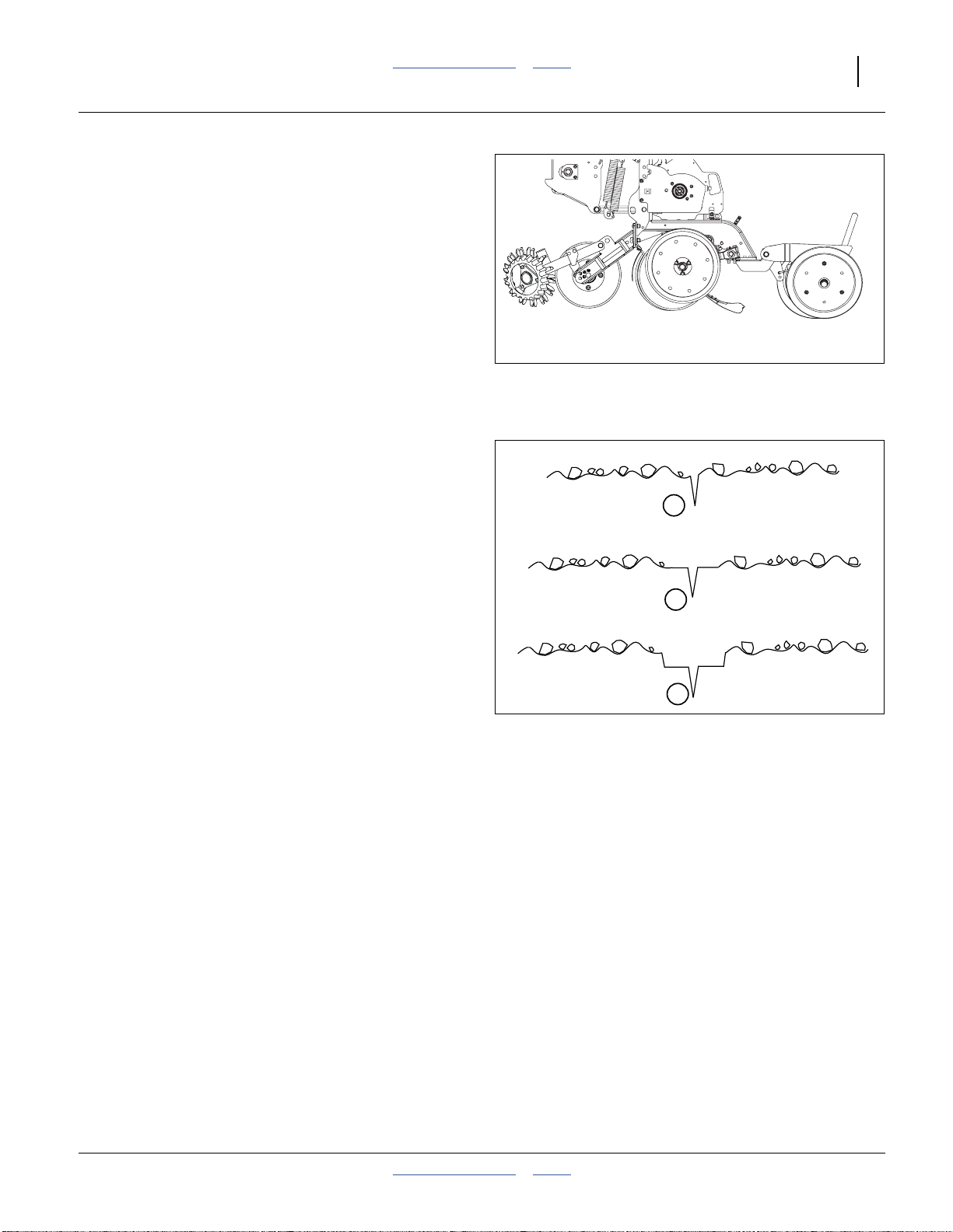
Great Plains Manufacturing, Inc. Table of Contents Index Adjustments 61
Row Unit Down Pressure
Refer to Figure 62
The ideal amount of down-force causes the side gauge
wheels to compress any loosesurface soil, butnot press
a trench into subsoil.
To assess down-force, operate the planter for a short
distance on typical ground (with or without seeding), and
stop. Leave the planter lowered (row units in ground).
At several row units, inspect the furrow created by the
opener discs, but prior to furrow closing by the press
wheels.
Note: Be sure to inspect rows both in and out of tire
tracks.
Refer to Figure 63
1. If the side gauge wheels are leaving no tracks, or
light tracks, increase down-force.
2. If the wheels are compressing trash and loose soil,
and leaving clear tracks right at the top of the
subsoil, down-force is probably correctand needsno
adjustment.
3. If the wheels are creating a trench into the subsoil,
down-force is too high and needs to be reduced.
Figure 62
Checking Furrow
Light or no side gauge
wheel tracks
Gauge wheels compress
loose soil only
Inspect Furrow Here
Insufficient down-force
Increase down-force
1
Ideal
No adjustment required
2
{
25193
Side gauge wheels
making deep tracks
Assessing Down-force
Down-force too high
Reduce down-force
3
Figure 63
2014-09-09 Table of Contents Index 401-312M
Page 66

62 3PYP Table of Contents Index Great Plains Manufacturing, Inc.
Refer to Figure 65
An adjuster cam sets down pressure individually for
2
each row unit. This isuseful for penetrating hard soiland
planting in tire tracks. For best results always adjust
tractor tires so they are not ahead of 30 inch rows.
Cam Notch Down-Force
a
2
3
zero (out of notch) Maintenance Only
one 345 lbs (156 kg)
5
two 370 lbs (168 kg)
three 400 lbs (181 kg)
four 450 lbs (204 kg)
6
five 500 lbs (227 kg)
six 550 lbs (249 kg)
4
tip Do Not Use
a. Includes both spring force and row unit weight.
Use only enough down pressure to cut the seed trench
and maintain proper soil-firming over seed. Excessive
row unit down force will lead to premature wear on row
unit components, uneven seed depth and gauge wheel
Figure 64
25 Series Row Unit
Spring Adjustment
25268
slippage (unless hydraulic down force is used).
Adjusting Down-Pressure
Refer to Figure 64 (on page 62,shown atcam setting 2),
Figure 65 and Figure 66
To adjust down pressure, use a 11⁄8inch (29 mm) open
end wrench or the tool stored under the walkboard.
3
3PYP must be unfolded for this adjustment.
1. Raise the planter. Although this adjustment can be
made with the planter lowered, the springs will be in
tension, and will require more effort. The extra force
required may also damage tools.
2. Install lift assist cylinder locks.
3. Put tractor in Park and shut it off.
4. Position wrench on the fixed nut near or slightly
4
Figure 65
Row Unit Minimum Cam (one)
27065
forward of vertical.
5. Pull upper spring link back.
5
6. Move the adjustment cam to the new setting on the
spring adjust bar .
6
Note: Do not set all rows higher than notch four. Using
high settings across all rows causes uneven
planting. Individual rows may be set higher if
running intire tracks.
Figure 66
27065
Row Unit Maximum Cam (six)
401-312M Table of Contents Index 2014-09-09
Page 67

Great Plains Manufacturing, Inc. Table of Contents Index Adjustments 63
Row Unit Shut-Off
Skip-row operations, such as planting from every other
row when switching from 30 inch twin-row to 30 inch
single-row, requires shutting down unused rows.
Refer to Figure 67
Shutting off seeding at a row involves 4 to 7 steps:
1. Identify the rows to shut off.
2. Disengage row unit drive coupler.
3. Close seed flow to row at Y-tube (if present).
4. Lock up row unit to reduce wear (optional).
5. Reset marker extension (if used).
6. Reset monitor active row pattern and row spacing to
avoid nuisance alarms (always done).
7. Shut off fertilizer drop lines (Option, see Seed and
Fertilizer Rate manual 401-312B for details).
8. Identify Rows to Shut Off
On twin-row planters, openers are installed with short
and long opener mounts. If locking up unused rows of a
twin-row planter, shut off the rear (long mount) rows.
On single-row planterswith mid-length mounts, any rows
may be locked up.
9. Close Y-Tubes
Refer to Figure 68
If any shut-off rows are served by a Y-tube, close the
valvefor the branchto that row. Rotate the valve capuntil
the indicator/handle is perpendicular to the tubes.
Closing the Y-tube prevents seed from entering an
unused hose, reducing waste and simplifying clean-out.
Figure 67
Row Unit Drive Coupler
Engaged (Left) and
Disengaged (right)
26171
Figure 68
29758
Y-Tube Open and Closed
2014-09-09 Table of Contents Index 401-312M
Page 68

64 3PYP Table of Contents Index Great Plains Manufacturing, Inc.
Row Unit Lock-Up
Alternate twin-row units (the rear units) can be pinned in
the up position to accommodate single-row spacing.
Refer to Figure 69
The lock-up pins for each rearrow unit arelocated in a
storage hole in the row unit mount. To lock up a unit,
the unit must be raised, and the pin moved to thelock-up
hole in the row unit shank.
3
Note: If you lose a pin, the replacement part number is
805-033C
1. Raise the planter. Although this adjustment can be
made with the planter lowered, the springs will be in
tension, and will require more effort. The extra force
may also damage tools.
2. Install lift assist cylinder locks. Lower parking stands.
3. Unhitch tractor. Move row mode spacer on an older
planter (see page 158).
4. Set the down pressure springs be set to the
minimum setting, per the instructions on page 61.
5. Raise the row unit high enough that the hole for the
pin is above the lower parallel arm. This can be done
in several ways, including:
a. use a hoist at the rear of the shank
b. use a jack under the shank extension
1
2
4
5
3
2
5
Figure 69
25 Series Row Unit
Lock-Up Pin
3
1
4
25269
25118
Machine Damage Risk:
Raising a row unit on a block by lowering the planter is risky.
Full lowering can easily damage components, and hydraulic
failure is a safety hazard.
Crushing and Sharp Object Hazards:
Do not attempt to lift the row unit by hand. The weight of the
unit, plus the force of the springs (even at minimum) is too
great (plus, a free hand is needed for pin insertion). Even with
multiple people lifting, hand-lifting is unsafe - there are
numerous sharp edges, and the row unit will snap down
violently if a grip is lost.
Refer to Figure 70
6. Remove the pin from the storage hole and insert
and secure it in the lock-up hole .
7. Lower row unit until lower parallel arm rests on
lock-up pin.
8. Shut off Y-tube port for the current row unit.
9. Disengage meter coupler.
10. Repeat for all rows needing lock-up.
2
3
Figure 70
25 Series Row Unit
Locked Up
Machine Damage Risk:
Do not pin the row unit while it is in the lowered position.
If the pin is inserted below the parallel arm, unit damage will
occur when planting begins.
25270
401-312M Table of Contents Index 2014-09-09
Page 69

Great Plains Manufacturing, Inc. Table of Contents Index Adjustments 65
Unit-Mount Cleaner Adjustments
Refer to Figure 71 and Figure 72
Optional Martin row cleaners are unit-mounted, using:
UMRC: Unit-Mount Row Cleaner (stand-alone), or
UMC-RC: Unit-Mount Coulter RC (on coulter bracket,
with or without a coulter disk present).
There are two adjustments:
1. Wheel placement (forward or aft mounting hole, for
more or less aggressive cleaning), and
2. Wheel height, adjusted by a stop. Cleaner arms
float. The stop only sets the lowest position.
In UMRC mount, a pinned cross-tube on the mount
3
adjusts the depth. In UMC-RC (coulter) mount, a sliding
down-stop block adjusts how close to the ground the
6
row cleaners operate.
The row cleaner needs to be adjusted for your
conditions, crop changes, and as coulters and openers
wear.Ideally, cleaners contactonly the trash, and do not
disturb the soil. If allowed to “dig”, row cleaners can
reduce seed coverage.
Suggested initial depth is tine tips at ground level.
Make the adjustment with the planter raised. Install
lift-assist cylinder locks. Also check bolt tightnessprior
5
to each planting session, to avoid down-stop slippage.
To adjust the row cleaner:
1. Determine the height adjustment required. Measure
from the lowest tine to the ground. Determine the
desired new measurement.
2. Support most or all of the weight of the arm to
prevent injury and ease the adjustment. Loosen
5 2
bolts on UMC-RC. Remove bent pin on UMRC.
3. Support arm at desired height.
4. UMRC: Slide adjustment tube until cross-tube
contacts arm at target height. Insert bent pin in
1 3
2
whichever hole pair is most in alignment. Each
possible hole pairing adjusts thetine height byabout
3
⁄4inch (19 mm).
5. UMC-RC: Slide the down-stop on the arm :
6 4
- back toward the pivot for shallower cleaning, or
- forward toward the tines for deeper cleaning.
Tighten the bolts .
5
6. Check the new height measurement.
Refer to Row Cleaner manual 204-085M-A for further
information on use, adjustment and maintenance of row
cleaners.
Sharp Object Hazard:
Row cleaner tines, castingedges and coulterblades are sharp.
Wear hand protection when working in this area.
UMC-RC: Row Cleaner Adjust
1
2
Figure 71
UMRC: Cleaner Adjust
4
5
6
Figure 72
3
27308
27341
2014-09-09 Table of Contents Index 401-312M
Page 70

66 3PYP Table of Contents Index Great Plains Manufacturing, Inc.
Coulter Adjustments
The ideal operating depth for coulters is1⁄4inch (6 mm)
above opener depth. Although they may have originally
been set to this depth, coulter (and opener) blades wear
with time, and may need adjusting.
Adjusting the coulter depth is accomplished by
re-mounting the coulter blade in one of the six mounting
holes arranged in a staggered pattern in the coulter
bracket.
Refer to Figure 73 and Figure 74
Raise planter andinstall cylinderlocks before working on
coulters. Row unit may be fully lowered or locked up. Do
not attempt to move blade when the current or new
position causes it to contact the ground during the
adjustment. Becareful around the front end of row units.
Row clear tines and coulter blades may be sharp.
To adjust coulter depth:
1. Determine the present opener and coulter depths.
2. Note which bracket hole the coulter is presently
using.
3. Determine which new hole will position the coulter
closer to the
below. If none, don’t move it.
4. Remove the5⁄8-11×4 inch bolt, lock washer and nut
( inFigure 73).
7
5. Move the blade to the new position. Insert the bolt,
and tighten on the lock washer and nut.
Hole
Number
1
⁄4inch above depth. See the table
Depth of (new) coulter bladerelative
to (new) opener blades
Figure 73
25 Series Unit-Mounted Coulter
2
3
5
1
4
6
7
29124
2 1 inch (2.5 cm) above
3
5
1 0
4
6
6. Re-adjust openers, if installed.
If a worn coulter cannot be adjusted to satisfactory
operating depth, replace coulter.
401-312M Table of Contents Index 2014-09-09
5
⁄8inch (1.6 cm) above
1
⁄4inch (6.4 mm) above
3
⁄8inch (9.5 mm) below
3
⁄4inch (1.9 cm) below
Figure 74
Coulter Blade Mounting Holes
29125
Page 71
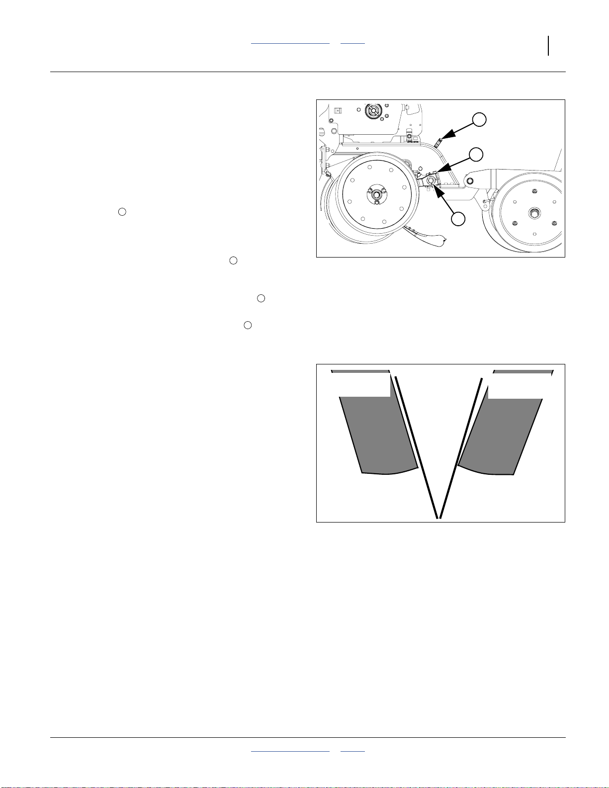
Great Plains Manufacturing, Inc. Table of Contents Index Adjustments 67
Row-Unit Opener Adjustments
25 Series openers have three adjustments:
1. Planting/seed depth.
2. Gauge wheel/opener disk clearance.
3. Opener disk angle.
Setting Planting Depth
Refer to Figure 75
The “T” handle sets planting depth by limiting the how
high the side depth gauge wheels ride relative to the
opener disks. The position of the seed tube itself is fixed
relative to the disks, and is not adjusted.
To adjust seed depth, pull the “T” handle up and back,
move it forward or aft, andset it back in adifferent pair of
holes in the scale.
• The shallower planting, move the “T” handle
forward.
• For deeper planting, move the “T” handle back.
Changing plantingdepth may also require changing disk
angle.
Disk Angle and Side Depth Wheels
Refer to Figure 76
Disk angle affects seed groove angle/width, and may
need to be narrowed to achieve the desired seed depth
in some conditions.
Disk-to-wheel angle and clearance ideally has the wheel
just touching the disk when the wheel is raised to
planting depth (is up against the stop set by the “T”
handle). The goal is to have both disks and wheels turn
freely, butkeep soil andtrash from getting between them.
These two adjustments interact with each other.
Changing one requires at least checking the other.
In addition to changing the disk angle due to changing
depth or new field conditions, these two settings may
need attention over time as the disk and wheels wear
from normal use. This adjustment will also need to be
made if any opener components are replaced.
1
1
1
1
Figure 75
Opener Adjustments
Side Depth
Wheel
Opener
Disks
Incorrect
Figure 76
Disk/Depth Wheel Alignment
1
2
3
25118
Side Depth
Wheel
Correct
2014-09-09 Table of Contents Index 401-312M
Page 72

68 3PYP Table of Contents Index Great Plains Manufacturing, Inc.
Adjusting Disk Angle & Side Depth Wheels
Refer to Figure 77
For 2 inch planting depth, adjust side depth wheel angle
so wheels contact row unit disks at the bottom of wheel.
Check with row units in soil so wheels are held up.
At the same time, keep side gauge wheels close to
opener disks so openers do not plug with soil or trash.
Note: Wheels should be out far enough so disks and
wheels turn freely.
Refer to Figure 78
To adjust side gauge wheels:
1. Raise planter slightly removing weight from side
gauge wheels.
2. Loosen hex-head bolt . Move wheel and arm out
1
Contact Within this Area
Figure 77
Opener-Depth Wheel Contact
22531
on O-ring bushing.
3. Loosen pivot bolt . Turn hex adjuster so indicator
notch is at 5 o’clock to 7 o’clock.
4
2 3
1
Note: Use this as the starting point foradjustment.
4. Move wheel arm in so side gauge wheel contacts
row unit disk. Tighten hex-head bolt to clamp arm
1
around bushing and shank.
5. Checkwheel-to-disk contact at 2 inch planting depth.
1
3
2
Lift wheel 2 inch and release. When let go, wheel
should fall freely.
• If wheel does not contact disk atbottom to area where
blade leaves contact with soil, move hex adjuster until
wheel is angled for proper contact with disk.
• If wheel does not fall freely, loosen hex-head bolt
and slide wheelarm outjust until wheel and arm move
freely. Retighten hex-head bolt according to grade:
1
⁄2inch Grade 5 bolt on 25 series, 75 foot-pounds.
1
⁄2inch Grade 8 bolt on 25 series, 110 foot-pounds.
1
1
4
Starting Point
Disk/Depth Wheel Adjustment
4
Figure 78
22524
22525
Note: Use “Torque Values Chart” onpage 126 for
reference.
6. Keep turning hex adjuster and moving wheel arm
until the wheel is adjusted properly. When satisfied,
tighten pivot bolt to 110 foot-pounds.
2
401-312M Table of Contents Index 2014-09-09
Page 73

Great Plains Manufacturing, Inc. Table of Contents Index Adjustments 69
Row-Unit Opener Disk Adjustments
Opener Disc Contact Region
Refer to Figure 79
Opener disc angle and stagger is not adjustable, but
disc-to-disc spacing is, and may need attention as discs
experience normal wear. Spacers will need to be reset
when blades are replaced.
The ideal spacing causes the blades to be in contact for
about one inch . If you insert two pieces of paper
between the blades, they should slide to within zero
(touching) to 1.5 inch (3.8 cm) of each other. If zero, the
gap between the blades should not be significantly
greater than the thickness of two sheets of paper.
If the contact region is significantly larger or there is a
large gap, it needsto be adjustedby moving one ormore
spacer washers.
Adjusting Disc Contact
Refer to Figure 79 and Figure 80
1. Raise the planter and install lift cylinder locks.
2. Remove the side gauge wheels on the row unit in
need of adjustment.
3. Remove the bolt retaining the opener disc on
one side. Carefully remove the disc. Do not lose the
hub components and spacer washers , . Make
note of how many spacer washers are between
the disk and the nut bar .
Note: When thebolt is fully removed from the disk, adust
cap or hold-down bracket will be loose.
4. To reduce thespacing betweenthe discs(the normal
case), move one spacerwasher from theinside to
the outside of the disc. Do not discard any
spacers. They will be moved to the inside upon
eventual replacement of a completely worn out
blade.
5. Re-assemble and check disk contact.
1
2
3 4
5 6
5
7
8
5
6
Opener Disc Contact Region
7
1
Figure 79
8
5
4
Figure 80
Opener Disc Spacers
2
26127
6
3
26128
2014-09-09 Table of Contents Index 401-312M
Page 74

70 3PYP Table of Contents Index Great Plains Manufacturing, Inc.
Adjusting Depth Wheel Scrapers
Refer to Figure 77
Scrapers are optional, and may be useful in moist or
sticky soils that tendto accumulateon gauge wheelsand
2
reduce intended planting depth.
To adjust scrapers:
1. Loosen nut .
2. Slide scraper toward gauge wheel until scraper
1
2 3
touches tire.
3. Slide scraper away from wheel leaving a
1
⁄8inch (3.2 mm) gap at .
2 3
4
4
3
1
4. Rotate scraper left and right around bolt, making
sure it cannot touch tire if bumped in field. If it can
touch tire, back scraper away from wheel until it
Figure 81
Gauge Wheel Scraper
25273
cannot.
5. Center scraper angle on bolt until gap is
1 4
constant.
6. Tighten nut .
1
Seed Meter Setup and Adjustment
Your 3PYP was originally supplied with a specific seed
meter type and internal components optimized for a
particular crop. Depending on the meter type and
configuration, there may be adjustments available.
You can also entirely change the meter, or swap internal
components, as your crop mix changes. This manual
section assumes that you need to install new meters,
then describes their internalconfiguration, andfinally any
adjustments.
Meter Removal
1. Clean out the meter. See “Meter Removal” on
page 70.
Refer to Figure 82
2. Slide the retaining ring up on the seed hose, and
remove the seed hose.
The 3PYP supports
• Great Plains Singulator Plus™ meters and
• Finger-pickup meters.
The 3PYP does not support feeder cups. Use a
Singulator Plus™ meter with specific wheels for
volumetric applications.
Figure 82
Seed Hose Retaining Ring
22883
401-312M Table of Contents Index 2014-09-09
Page 75

Great Plains Manufacturing, Inc. Table of Contents Index Adjustments 71
Refer to Figure 83
3. Release the lower latch.
Refer to Figure 84
4. Release the upper latch and swing the meter mount
away from the meter.
Refer to Figure 85
5. Lift up, then back, and remove the meter.
Figure 83
Lower Meter Latch
Figure 84
Upper Meter Latch
22911
22911
Figure 85
22912
Singulator Meter Removal
Refer to Figure 86
6. While the meter is removed, take time to inspect the
meter drive chain , idlers and drive sprocket ,
1 2 3
and perhaps perform the periodic chain lubrication.
3
1
2
Idlers are spring-loaded, so no slack adjustment is
required.
Figure 86
21917
Inspect Meter Drive
2014-09-09 Table of Contents Index 401-312M
Page 76

72 3PYP Table of Contents Index Great Plains Manufacturing, Inc.
Singulator Plus™ Meter Wheel Replacement
Choose the correct seed meter wheel for the type of
seed you will be using. Be sure to use the same wheel
type on all meters.
25 Series Meter Wheels Not Interchangeable:
Seed meter wheels for the 25 Series row units are made of a
green color material and are not interchangeable with the
other Great Plains seed meter wheels, discs and plates for
other machines. Use only green wheels in 25 Series row units.
1. Clean out meter. For more information, see “Meter
Removal” on page 70
Refer to Figure 87
2. Push in spring-loaded wheel retainer and make
1
⁄4turn. Pull off wheel retainer and spring.
Refer to Figure 88
3. Pry the seed meter wheel out about1⁄4inch using
the tool stored under the walkboard, and spin
backward to clean out seeds from top pockets.
Figure 87
Singulator Plus™ Wheel Retainer
Figure 88
Pry Meter Wheel
22911
22913
Refer to Figure 89
4. Remove seed meter wheel.
Refer to Figure 90
Note: With the seed meter wheel removed,youmay want
to check the meter forinternal damage or trash.
Note: Some wear on topedge of slide isnormal. Excess
wear is cause for replacement.
5. When changing crops be sure to clean out air
system before installing new meters or wheels. See
“Cleaning Out Air System” on page 87
6. Place new wheel on meter wheel shaft. Seat wheel
fully on cross-pin.
7. Replace spring-loaded wheel retainer. Make1⁄4turn
to seat cross-pin in shallow groove of retainer.
Figure 89
Remove Wheel
Figure 90
Inspect Meter
25274
22884
401-312M Table of Contents Index 2014-09-09
Page 77

Great Plains Manufacturing, Inc. Table of Contents Index Adjustments 73
Meter Installation
Installation is the reverse of the removal process, with
two steps omitted.
Refer to Figure 91
1. Insert the meter.
Insert the top meter tab (with the hook).
1
Align the meter base with the latch plate ears.
2
Insert the bottom meter tab.
3
1
Mind the lower latch, as it tends to swing under the
meter base and block mating with the latch plate.
Refer to Figure 84 on page 71
2. Engage the upper latch.
Refer to Figure 83 on page 71
3. Engage the lower latch, and swing the mounting
plate into engagement with the meter. it may be
2
3
necessary to spin the drive coupler to ease this.
Refer to Figure 82 on page 70
4. Slide the seed hose over the meter inlet tube, and
then slide the retaining ring down the seed hose.
Refer to Figure 92
5. Release the upper latch.
Figure 91
Install Meter
Figure 92
Upper Meter Latch
25275
21922
2014-09-09 Table of Contents Index 401-312M
Page 78

74 3PYP Table of Contents Index Great Plains Manufacturing, Inc.
Finger Meter Adjustments
The finger pick-up meter has an adjustable brush, and
alternate inserts are available for the backing plate. The
brush has been pre-set to the optimum setting for most
seed sizes. The factory-installed insert is the “A” insert.
1
Optimum planting speed is 4
⁄2to 5 miles per hour
(7.2-8 km/h). Excess speed causes poor spacing
performance due to seed tube bounce, and may also
cause improper depth control due to row unit bounce.
Finger Meter Brush Adjustment
The brush reduces or eliminates “doubles” (delivering
two seeds per finger), but if set too aggressively can
cause “skips” (delivering no seed on some fingers). As
needed, adjust for minimal doubles and skips.
Note: These instructions describe the current finger
pickup meter shipped with new Great Plains
planters, which has anintegrated adjustment lever
forthe brush.If youhave added pre-existingfinger
meters after purchase, there is some chance that
you may have the previousmodel meter, adjusted
by screwdriver ratherthan lever. If so,rely on
counting detents to determine the setting. Not all
have 9 detents.
Refer to Figure 93
The adjustable brush provides additional flexibility to
accommodate a wide range of seed sizes. Use lever (L)
to gently rotate the brush into position.
The settings range from 1 to 5 with detents at each half
step, for a total of 9 detents. The factory default setting is
1
2
⁄2. Although the numbers are molded into the meter
housing, only “1” and “5” may be visible. To ensure
consistency, rotate the lever fully counter-clockwise
L
(1), and count detents as you advance it to the desired
setting.
Always pay attention to your planter monitor. Compare
actual seed usage to your estimates.
Fine-tune your planter by thoroughly checking all key
components including: seed tubes, chains, sprockets,
tire pressure, seed monitor, double disk openers, gauge
wheels, seed firmer, closing wheels, parallel arms, and
the row unit itself.
L
3
4
2
5
1
Figure 93
25276
Finger Meter Brush Lever
Use the general guidelines in the table at right to adjust
the brush position to your seed size and shape. The
numbers listed correspondto thenumbers printed onthe
outer housing of your meter. If there is a decal on your
meter, its units are seed size in pounds per 80,000 seed
bag.
Bag Weight Seeds Per Brush Seeds Per Bag Weight
(80,000 seeds) Pound Setting Kilogram (80,000 seeds)
Rounds
65 lbs 1230 or less 1 2710 or less 29.5 kg
65 to 55 lbs 1230 to 1450 2 2710 to 3195 29.5 to 24.9 kg
55 to 45 lbs 1450 to 1780 3 3195 to 3925 24.9 to 20.4 kg
45 to 35 lbs 1780 to 2300 4 3925 to 5070 20.4 to 15.9 kg
35 lbs 2300 or more 5 5070 or more 15.9 kg
Flats
45 lbs 1780 or less 1 3925 or less 20.4 kg
45 to 35 lbs 1780 to 2300 2 3925 to 5070 20.4 to 15.9 kg
35 lbs 2300 or more 3 5070 or more 15.9 kg
29633
401-312M Table of Contents Index 2014-09-09
Page 79

Great Plains Manufacturing, Inc. Table of Contents Index Adjustments 75
Finger Meter Inserts
Refer to Figure 94
The backing plate is equipped with an “A” insert for
Corn, and a “C” insert for Sunflower. In tests, these
inserts providethe best performance in mostseed sizes.
2
2
3
However, there are alternate inserts that can be used.
Before changing to a different insert, please consult with
a Great Plains service representative for a
recommendation.
The inserttype ismolded intothe back. Changing inserts
requires meter disassembly.
1
Meter Reliability Risk:
Be cautious in using seed treatments, additives, and other
chemicals when possible. They can cause meter performance
problems and premature wear. If graphite is used, use
Precision Planting® planting graphite or Great Plains
graphite, which is less abrasive. Generally, seeds treated with
Maxi, Captan, and similar coatings benefit from graphite.
Always store meters in a dry, secure place. Moisture,
Figure 94
Finger Meter Insert
22908
temperature, nest-building insects and rodents can create
problems. Always pay attention to your seed monitor and
operating manual. Monitor the amount of seed you are
planting compared to expectations. Investigate abnormalities!
Sunflower Meter Configurations
Review the finger pickup meter configuration, based on
the seed size. See chart below. See “Exchanging
Finger Sets” on page 94 for component removal and
installation instructions.
The standard Sunflower configuration is suitable for
#4 and #3 seed sizes. Larger seeds may require the
Corn meter configuration.Using a fingerpickup meterfor
Confection seeds is not recommended.
Finger Pickup Configurations for Sunflower
Oil Seed Size Confection Seed
#4 #3 #2
Meter Component
Finger Set
~16500 seeds/kg
(~7500 seeds/pound)
343067
s
~14300 seeds/kg
(~6500 seeds/pound)
343067
s
~12100 seeds/kg
(~5500 seeds/pound)
343029
c
(12-finger sunflower) (12-finger sunflower) (12-finger corn)
Backing Plate
342108
s
342108
s
342110
c
(Insert C) (Insert C) (Insert A)
Brush Block
343091
(brushless
s
343091
(brushless
block)
c. These components are included in the standard 890-856C Corn meter. 34573
s. These components are included in the standard 890-912C Sunflower meter, and the 403-659A Conversion Kit.
2014-09-09 Table of Contents Index 401-312M
block)
s
343052
c
(adjustable
brush block)
(long, narrow, XL)
~6600 seeds/kg
(~3000 seeds/pound)
Not
recommended
for XL
confection
seed
Page 80

76 3PYP Table of Contents Index Great Plains Manufacturing, Inc.
Sprocket Indexing (Stagger)
(Applies to both ground and hydraulic drive)
28420
If you are planting:
• finger-metered,
• twin-row crops,
• at seed interval spacings above 61⁄2inches,
you can synchronize each pair of adjacent meters in a
twin row sothat you achieve the maximum seed-to-seed
spacing between the units of the pair.
Refer to the Seed Rate manual for details.
Seed Firmer Adjustments
25 Series row units include a standard seed flap, and
accept one of two optional seed firmers.
Keeton® Seed Firmer Adjustment
The optional Keeton® Seed Firmer is an engineered
polymer shape that slides down the seed furrow. It traps
seeds as they exit the seed tube and firms them into the
bottom of the “V”.
Refer to Figure 95
The firmer is provided with a preset tension which is
recommended for using the first year. The tension
screw can be tightened in subsequent years
according to your needs. Firmers should provide just
enough tension to push seeds to the bottom of the
trench.
Measure the distance from the ground to the head of the
tension screw. This distance should be 4 to 41⁄2inches If
not, loosen the bolts in the mounting bracket and select
different holes until the proper measurement is attained.
Seed-Lok® Seed Firmer Lock-Up
Optional Seed-Lok® firming wheels provide additional
seed-to-soil contact. The wheels are spring loaded and
do not require adjusting. In some wet and sticky
conditions the wheels may accumulate soil. To avoid
associated problems, you can lock-up the firmers.
s
Sharp Object Hazard:
Row unit disk blades may be sharp. Use caution when making
adjustments in this area. To adjust the Keeton® seed firmer,
lower the planter until the disks of the row units are resting on
the ground.
s
Figure 95
Keeton® Seed Firmer
20327
401-312M Table of Contents Index 2014-09-09
Page 81

Great Plains Manufacturing, Inc. Table of Contents Index Adjustments 77
Refer to Figure 96 (which depicts a rowunit with discs, side
depth wheels/arms andpress wheels removed for illustrative
purposes - removal is notnecessary for lock/unlock)
To lock up Seed-Lok® wheels:
1. Raise planter. Insert lift assist cylinder locks.
®
2. Lift Seed-Lok
free to rotate.
3. Rotate lever stop to side/idle position . Release
lock-up handle .
4. Push up on Seed-Lok® wheel until wheel arm
latches up .
To release a locked-up Seed-Lok®:
1. Insert a
handle . Alternatively, lift up on the wheel .
2. Rotate the handle clockwise (handle arm up) until
the Seed-Lok® wheel releases at the latch point
and falls free.
3. While holding the handleup, rotate the raisedportion
of the lever stop under bothsides of the handle
at the arm end. Remove the tool.
Note: Engage the lever stopunder thehandle when
1 4
Seed-Lok®is in use. Ifleft disengaged , afurrow
obstruction could cause unintendedlock-up.
lock-up handle untilleverstop is
1
5
1
⁄4in. tool drive tip in the tool hole of the
2 2
1 2
3
4
6
5
2
3
6
1
3
2
4
5
Figure 96
Seed-Lok® Lock-Up
31543
Press Wheel Adjustment
The press wheels close the furrow which gently presses
the soil over the seed to ensure good seed-to-soil
contact for even emergence.
To provideconsistent seedfirming, the press wheels are
free to move downward from their normal operating
position. This system maintains pressing action even if
the row unit arm is lifted when the disks encounter
obstructions.
Refer to Figure 97, 98 and 99
There are three adjustments available on the press
wheel assembly and a fourth option on press wheel
assemblies with cast wheels:
1. Down pressure (shown at maximum)
2. Wheel stagger (shown staggered)
3. Centering (see Figure 99 on page 78)
4. Cast Wheel Plow Angle (see Figure 100 on page 79)
3
2
Figure 97
Press Wheel Adjustments
1
25118
2014-09-09 Table of Contents Index 401-312M
Page 82

78 3PYP Table of Contents Index Great Plains Manufacturing, Inc.
Press Wheel Down Pressure
Handle sets down pressure, which may need
adjustment for different soil types and field conditions.
• Relax the handle forward (in the direction of travel)for
• Pull the handle back for increased down pressure.
Note: Higher press wheel down pressures reduce the
Press Wheel Stagger
The factory stagger setting has been found optimal for
residue flow. If your conditions appear to require even
press wheels, you might try one row before reconfiguring
the entire planter. To change the stagger:
1. Raise the planter and install the lift assist cylinder
2. Remove the bolt , nut and lock-washer for the
3. Move the spacer and wheel to the forward of
4. Re-install the bolt, lock washer and nut. Tighten.
1
decreased down pressure.
1
down force on the main row unitshank
components, such as the openers. High press
wheel settings may require an increase in overall
row unit down force. See page 61.
locks. See “Lift Assist Cylinder Lock-Up” on
page 26
5 6 7
left press wheel .
the two mounting holes at .
9
8 9
2
3
Press Wheel Force & Stagger
1
6
7
Figure 98
2
8
9
5
22907
Press Wheel Centering
If one press wheel is running in the seed trench, or the
wheels are not centered over the trench, the angle of
the press wheel assembly can be adjusted as follows:
1. Determine how far, and in which direction, the press
wheel assembly needs to move tocenter the wheels.
2. Raise planter andinstall liftassist cylinderlocks.See
“Lift Assist Cylinder Lock-Up” on page 26
3. Pick some reference points on the unit to be
adjusted and an adjacent row unit. Measure the
distance between them.
4. Loosen the rear1⁄2inch hex-head bolts .
Note: Do not loosen thetwobolts forwardof the hex-head
bolts.One of the forward bolts is square-head. The
other may be hex orsquare.
5. Turn the hex head cam under the forward hex
head bolt , and obtain the new distance between
the reference points.
6. Tighten both hex head bolts .
b
c
b
b
a
b
b
c
Figure 99
Press Wheel Centering
a
25277
401-312M Table of Contents Index 2014-09-09
Page 83

Great Plains Manufacturing, Inc. Table of Contents Index Adjustments 79
Press Wheel Assembly with Cast Wheels
Tight soil may require the need to drag/plow the trench
closed. The factory setting on press wheel assemblies
with cast wheels is 4° (maximum plow). If the conditions
in your region appear to require less plow, there are two
additional settings: 2° (less plow) and 0° (no plow). To
change the plow setting:
Refer to Figure 100
1. Raise planter andinstall liftassist cylinderlocks.See
“Lift Assist Cylinder Lock-Up” on page 26.
2. Remove the bolt , lock-washer and spacers
for the press wheel .
3. Remove bolt , flat washer and hex nut for
casting .
4. Place a3⁄4inch open end wrench on tab of
casting. Rotate casting untilthe desiredangle setting
(4°, 2° or 0°) hole lines up with a hole on the press
wheel mount weldment (only one set of holes will
line up for each setting).
5. With holes lined up replace casting bolt and flat
washer . Secure with hex nut .
6. Reinstall press wheel.
If press wheel adjustments do not provide satisfactory
furrow closing, your conditions may require alternate
press wheels. A variety of wheel assemblies are
available. Consult your Great Plains dealer.
7
5 6
1 2 3
9
4 5 6
7
8
4
5
4
2
1
Figure 100
Press Wheel Plow Angle Setting
6
8
7
3
9
34011
2014-09-09 Table of Contents Index 401-312M
Page 84

80 3PYP Table of Contents Index Great Plains Manufacturing, Inc.
Troubleshooting
General Troubleshooting
Problem Cause Solution
Planting too
much
Planting too
little
Incorrect seed rate. Check seed rate information in the seed monitor manual.
Actual field size is different. Verify field size.
Excessive overlap.
Irregular shaped field.
Incorrect tire size or air pressure. Correct tire size and air pressure, page 125.
Improper sprocket. Check sprockets
Improper gap on speed sensor. Checkspeed sensor on planter for1⁄16inch to1⁄8inch gap
Meter wheel or finger pickup has more
cells than indicated on seed rate chart.
Incorrect seed rate. Check seed rate information.
Excessive field speed. Reduce field speed.
Seed size and weight may vary. Adjust seed rate handle.
Incorrect tire size or air pressure. Correct tire size and air pressure, page 125.
Actual field size is different. Verify field size.
Excessive gaps between planter
passes.
Plugged row-unit seed tube. Lift planter, expose bottom of seed tube and clean out.
Thrown or worn drive chains Check drive chains.
Worn sprockets and/or chain idlers. Replace sprockets and/or chain idlers.
Improper sprocket. Check sprockets
Improper gap on speed sensor. Check speedsensor on planterfor1⁄16inch to1⁄8inch gap
Meter wheelor fingerpickup has fewer
cells than indicated on seed rate chart.
Adjust marker, page 54.
from wheel. Improper gap can cause erratic speed signal
causing monitor to falsely report improper planting rate.
Monitor may also falsely report a low rate onsoybeans by
as much as5 percentdue to difficulty in countingall of the
seeds.
Charts are based on either 6 finger or 12 finger meters or
various wheel counts.
401-312M Table of Contents Index 2014-09-09
Page 85

Great Plains Manufacturing, Inc. Table of Contents Index Troubleshooting 81
Problem Cause Solution
Uneven seed
spacing.
Uneven seed
depth
Row-unit
disks not
turning freely.
Hydraulic meter drive motor rpm too
low for reliable control by proportional
valve.
Excessive field speed. Reduce field speed.
Unclean seed. Use clean seed.
Seed-Lok
Row-unit disks not turning. See “Row-unit disks not turning freely.” in this
Plugged row-unit seed tube. Lift up planter, expose bottom of seed tube and clean out.
Worn/rusted sprockets and/or chain
idler.
Partially plugged row-unit seed tube. Lift up planter, expose bottom of seed tube and clean out.
Lack of proper seed lubrication on
seed.
Use of excessively sticky or wet seed
treatment.
Inadequate contact wheel spring
pressure.
Air pressure in contact wheel incorrect. Check for correct tire air pressure, page 125.
Excessive field speed. Reduce field speed.
Planting conditions too wet. Wait until drier weather.
Incorrect coulter depth setting. See coulter manual.
Excessive or improper row unit down
pressure spring setting.
Damaged seed tubes. Check seed tubes for damage.
Seed-Lok® building up with dirt. Lock up Seed-Lok®, page 76.
Row-unit not penetrating low spots. Adjust row-unit, page 62.
Rough planting conditions. Rework the field.
Seed firmer not in place and set to
correct tension.
Row-unit plugged with dirt. Clean row-unit.
Planting conditions too wet. Wait until drier weather.
Seed-Lok® is plugging row-unit. Lock up Seed-Lok®, page 76.
Failed disk bearings. Replace disk bearings.
Bent or twisted row-unit frame. Replace row-unit frame.
Partially plugged row-unit seed tube. Lift up planter, expose bottom of seed tube and clean out.
®
plugging. Lock up Seed-Lok®, page 76.
1. Increase field speed.
2. Use a seed wheel with lower cell count.
Switch from 12 finger meters to 6 finger meters.
3. Install a low speed kit (page 115).
Troubleshooting chart.
Check and replace any worn/rusted sprockets or chain
idlers.
Refer to Seed Lubricant, page 119.
Check your treatment.
Check for correct tire air pressure, page 125.
See 25 Series row-units, page 62.
Refer to Keeton® Seed Firmer, page 76.
2014-09-09 Table of Contents Index 401-312M
Page 86

82 3PYP Table of Contents Index Great Plains Manufacturing, Inc.
Problem Cause Solution
Press wheels
not
compacting
the soil as
desired.
Excessive
seed
cracking.
Press wheel
or row-units
plugging
Air lines
plugging
between air
box and Y
splitters
Too wet or cloddy. Wait until drier weather or rework ground.
Use of incorrectly shaped tire for your
conditions.
Incorrect press wheel depth. Reset press wheel depth, page 77.
Excessive field speed. Reduce field speed.
Unclean seed. Use clean seed.
Damaged, old or dry seed. Use clean, new seed.
Planting conditions too wet. Wait until drier weather.
Too much pressure on row-units. Reduce down pressure on row-units.
Coulters set too deep, bring up excess
dirt and moisture.
Planter not set to run level from frontto
rear, carrying enough weight on gauge
wheels to prevent “nosing over”, or set
too low on rear caster eyeboltsallowing
it to run “nose high”.
Backed up with planter in the ground. Clean out and check for damage.
Failed disk bearings. Replace disk bearings.
Disk blades worn. Replace disk blades.
Scraper worn or damaged. Replace scraper.
Fan too slow. Speed up fan.
Wedge shaped wheelswork best on narrow spacingsand
in wet conditions. Round edge wheels work best in wider
row spacings and drier conditions.
Check coulter adjustment.
Check see “Frame Height and Leveling” on page 18
Seed blowing
Fan too fast. Slow down fan.
out of
pro-box door
area
401-312M Table of Contents Index 2014-09-09
Page 87

Great Plains Manufacturing, Inc. Table of Contents Index Troubleshooting 83
Problem Cause Solution
Air line plug
between
Y-tube &
meter
Air lines
plugging
above air box
at fold area
Hydraulic
marker
functioning
improperly
Marker disk
does not
mark
Improper air hose routing. With machine folded the air lines should be tight. With it
unfolded they should form a gentle horizontal “S” shape
through the holders with no big sags.
Fan too slow. Speed up fan.
Improper air hose routing. With machine folded the air lines should be tight. With it
unfolded they should form a gentle horizontal “S” shape
through the holders with no big sags.
Air or oil leaks in hose fittings or
connections.
Low tractor hydraulic oil level. Check tractor hydraulic oil level.
Loose or missing bolts or fasteners. Check all bolts and fasteners.
Needle valve plugged. Open needle valve, cycle markersslowly andreset needle
Needle valve(s) in sequence valve
plugged.
Wing Fold Switch ON Turn Wing Fold switch OFF
Marker folding linkage does not have
enough slack to allow marker disk to
drop into field depressions.
Check all hose fittings and connections for air or oil leaks.
valve, refer to page 54.
Open needle valves, cycle markers slowly and reset
needle valves, refer to page 54.
Maximum down float should be limited by the slot at the
rod end of the marker cylinder, refer to page 54.
Reverse marker disk to pull or throw dirt.
2014-09-09 Table of Contents Index 401-312M
Page 88

84 3PYP Table of Contents Index Great Plains Manufacturing, Inc.
Airbox Troubleshooting
Problem Cause Fix
Single row doesn’t fill or keep up
with other rows.
Both rows on one meter outletlow
or not keeping up withother rows.
Note: This is more likely to occur
on end outlets.
Multiple rows fail for lack of seed. Fan speed too high/too low. Check/adjust fan speed.
Single or multiple hoses plugging
just ahead of airbox.
All rows fail. Lack of seed. Add seed.
1, 2, 3, or more outlets fail.
Note: Outlets can beside-by-side
or random. Plugging may
also move from one outlet
to another.
Little or no seed to many rows,
with heavily treated seed.
Y-tube is bent/angled off feed pipe. Loosen and rotate pipe so the bend is
straight down andY-tube is not pointing to
front or rear of air pipe.
Blockage in air slot in top of airbox. Clear by using a long slim tool and taking
hose off hose outlet or clean-out door.
Note: May be necessary to take top off
airbox to clear debris from slot.
Bad hose routing between delivery
hose and airbox on wing.
Out of seed. Add seed.
Fan speed too high/too low. Check/adjust fan speed.
Possible air leak. Check for air leak downstream between
Fan speed too high. Adjust fan speed.
Foreign matter in seed chamber in
bottom of airbox.
Seed treatment sticky. Add talc to seed to dry out seed treatment.
Correct hose routing.
box and top of meter.
Extremely high populations may require
slightly reduced field speed.
Clean out seed chamber.
401-312M Table of Contents Index 2014-09-09
Page 89

Great Plains Manufacturing, Inc. Table of Contents Index Troubleshooting 85
Steering Error Flash Codes
Failure and errors detected by the self-diagnostics in the
steering ECU are presented to the operator as a series
of flashes of the Power LED.
There are 2 to 12 flashes, interrupted by a short pause.
Multiple errors are flashed in rotation, with a long pause
between each errorcode. A maximum of fiveerror states
are reported in any single rotation.
Any of these errors causes the ECU to default the
hydraulic steering to “float”.
Code Diagnostic Corrective Action
1 - 1 Float valve HS short to battery
1 - 1 Float valve LS short to battery
1 - 2 Float valve HS short to ground
1 - 2 Float valve LS short to ground
1 - 3 Float valve open circuit
2 - 1 ST1 valve HS short to battery
2 - 1 ST1 valve LS short to battery
2 - 2 ST1 valve HS short to ground
2 - 2 ST1 valve LS short to ground
2 - 3 ST1 valve open circuit
3 - 1 ST2 valve HS short to battery
3 - 1 ST2 valve LS short to battery
3 - 2 ST2 valve HS short to ground
3 - 2 ST2 valve LS short to ground
3 - 3 ST2 valve open circuit
Check float valve coil and cable to ECU.
ECU is detecting an unexpected voltage in the circuit.
Check float valve coil and cable to ECU.
ECU is detecting a short to ground.
Check float valve coil and cable to ECU.
ECU is failing to detect presence of coil - no circuit continuity.
Check ST-1 valve coil and cable to ECU.
ECU is detecting an unexpected voltage in the circuit.
Check ST-1 valve coil and cable to ECU.
ECU is detecting a short to ground.
Check ST-1 valve coil and cable to ECU.
ECU is failing to detect presence of coil - no circuit continuity.
Check ST-2 valve coil and cable to ECU.
ECU is detecting an unexpected voltage in the circuit.
Check ST-2 valve coil and cable to ECU.
ECU is detecting a short to ground.
Check ST-2 valve coil and cable to ECU.
ECU is failing to detect presence of coil - no circuit continuity.
Check tractor wheel sensor for:
5 - 1 Tractor sensor short to ground
A. travel limits of sensor.
B. cable to ECU
C. function of sensor
5 - 2 Tractor sensor open circuit ECU not detecting tractor sensor. Use same steps as for 5 - 1.
6 - 1 Caster sensor short to ground Check caster wheel sensor, using same steps as for 5 - 1.
6 - 2 Caster sensor open circuit ECU not detecting caster sensor. Use same steps as for 5 - 1.
8 - 1 ECU low voltage
Check tractor voltage above 10Vdc.
Check connections to ECU. Check harnesses and switchbox connections.
Certain Machine Damage:
Do not back up if ANY of these errors occurs.
Steering is disabled.
The wheels cannot fully caster and machine damage will
result. If the problem cannot be corrected in the field, drive
forward to remove the planter from the field.
29894
2014-09-09 Table of Contents Index 401-312M
Page 90

86 3PYP Table of Contents Index Great Plains Manufacturing, Inc.
Maintenance and Lubrication
Maintenance
Proper servicing and maintenance is the key to long
implement life. With careful and systematic inspection,
you can avoid costly maintenance, downtime, andrepair.
Alwaysturnoff and removethe tractor key before making
any adjustments or performing any maintenance.
Crushing Hazard:
You may be severely injured or killed by being crushed under
the falling implement. Always have transport locks in place
and frame sufficiently blocked up when working on implement.
High Pressure Fluid Hazard:
Escaping fluid under pressure can have sufficient pressure to
penetrate the skin. Check all hydrauliclines and fittingsbefore
applying pressure. Fluid escaping from a very small hole can
be almost invisible. Use paper or cardboard, not body parts,
and wear heavy gloves to check for suspected leaks. If an
accident occurs, seek immediate medical assistance from a
physician familiar with this type of injury.
1. After using your planter for several hours, check all
bolts to be sure they are tight.
2. Remove excess slack from chains. Clean and use
chain lube on all roller chains as needed.
3. Maintain proper air pressure in planter tires.
4. Keep disk scrapers properly adjusted.
5. Clean planter on a regular basis. Regular and
thorough cleaning will lengthen equipment life and
reduce maintenance and repair.
6. Lubricate areas listed under “Lubrication” on
page 107.
7. Replace any worn, damaged, or illegible safety
labels by obtaining new labels from your Great
Plains dealer.
OFF
401-312M Table of Contents Index 2014-09-09
Page 91

Great Plains Manufacturing, Inc. Table of Contents Index Maintenance and Lubrication 87
Seed Clean-Out
Cleaning Out Air System
1. Shut off sliding door at bottom of seed box or bean
hopper.
2. Place a pan or tarp under the manifold to catch the
seed.
3. Open manifold door to empty seed from manifold.
Note: If needed, additional access doors are provided.
4. Shut door under manifold.
Refer to Figure 101
5. Close all Y-tubes.
6. If seed meters were cleaned out first, leave the
hoses disconnected at the meters.
7. Turn on the air fan and let it run.
8. Start at one end of planter and place a bucket under
the hose or meter to catch the seed. If hose is
connected, open clean-out door.
9. Open the Y-tube gate feeding that meter. Let the air
blow seed out. Keep the meter open for a couple of
minutes after the seed stops blowing out.
10. Close the Y-tube gate feeding that meter. Close the
meter clean out door.
11. Repeatprocedure on the next meter in line. Continue
with this procedure until you have reached the
opposite end of the planter.
Cleaning Out Meters
Refer to Figure 102
1. Place a bucketor pan undermeter to catchany seed
during clean-out.
2. Slide the retaining ring up and remove seed hose.
Singulating Meter
Refer to Figure 103
3. Pull clean-out door away from the opening and allow
seed to fall.
4. Removethe seedmeter wheel for thoroughcleaning.
Refer to “Seed Meter Setup and Adjustment” on
page 70 for more information.
Finger Pickup Meter
Refer to Figure 104
5. Pull clean-out door away from the opening and allow
seed to fall.
Figure 101
Cleaning: Y-Tubes
Figure 102
Disconnect Seed Tube
Figure 103
Singulating Clean-out Door
22843
22883
22885
Figure 104
21920
Finger Meter Clean-out Door
2014-09-09 Table of Contents Index 401-312M
Page 92

88 3PYP Table of Contents Index Great Plains Manufacturing, Inc.
Marker Maintenance
2
Marker Shear Bolt Replacement
Refer to Figure 105
If a marker gets caught or hits an obstruction, it is
designed to fail a shear bolt at the fold, pivot on a
second bolt , and swing back.
The shear bolt is a hex head cap screw,7⁄16-14×2 inch
Grade 5, Great Plains part number 802-589C, plus a
7
⁄16-14 lock nut, Great Plains part number 803-200C.
Install a replacement shear bolt on the vertical faces on
the side opposite from the pivot bolt . Do not use a
higher grade bolt, or marker hang-ups may result in
machine damage. Do not use a lower grade bolt, or you
may experience nuisance shears.
Refer to Figure 106
If your planting frequentlyencounters shear hazards,you
can store 6 spare shear bolts/nuts per marker side, in
storage holes at the fold point.
2
3
1
2
Figure 105
Marker Shear Bolt
1
25263
Marker Chain Length Adjustment
Great Plains suggests checking marker chain slack
every few years. If any maintenance orrepairs causethe
chain to be disconnected, correct slack needs to be set
on reinstallation.
Perform any checks and adjustments with the marker
folded and tilted down into its cradle.
Refer to Figure 107
At the midpoint in the exposed chain, pull it toward the
front of the planter.
Measure the distance between that mid-point and the
nearest point on either of the two parallel tubes of the
marker intermediate arm. The target value is:
18 inches (46 cm).
If theslack is outside this range, remove the bolt and nut
at the lower end of the chain and adjust the length.
3
1
Figure 106
Marker Shear Bolt Storage
Figure 107
Marker Chain Slack
A chain length too short or too long can result in marker
damage.
25264
25266
401-312M Table of Contents Index 2014-09-09
Page 93

Great Plains Manufacturing, Inc. Table of Contents Index Maintenance and Lubrication 89
Dual Marker Speed Adjustment
Crushing and Sharp Object Hazards:
You may be injured if hit by a folding or unfolding marker.
Markers may fall quickly and unexpectedly if the hydraulics
fail. Never allow anyone near the planter when folding or
unfolding the markers.
Refer to Figure 108 and Figure 109
Adjust folding speed for dual markers with hex
adjustment screws on the sequence valve body. The
valvesequence bodyis topleft center section, nearfront.
Loosen jam nuts before making adjustments.
There is one adjustment screw for fold-out speed and
one for fold-down speed . You can identify adjustment
2
1
screws by markings stamped in valve body.
Turn adjustment screws clockwise (S: slower) to
decrease folding speed and counterclockwise (F: faster)
to increase folding speed.
With tractor idling at a normal operating speed, adjust
marker folding to a safe speed. Excessive folding speed
could damage markers and void the warranty.
After adjusting thefolding speed, tightenjam nutson hex
adjustment screws to hold settings.
Figure 108
Marker Sequence Valve Location
S
1
2
Figure 109
Marker Extension Adjustment
25440
F
S
14048
Hitch Shims
Refer to Figure 110
(an exploded view- remove only specifiedparts)
If the planter tends to pull to the right or left, inserting,
moving or stacking hitch shims may correct the problem.
The standard planter hasone shim installed onthe left. A
spare hitch shim was shipped with the planter.
To remove or insert a shim:
1. Loosen the eight nuts and bolts on the lower
hitch, only on the side to be changed.
2. At the four set screws , loosen the four jam nuts.
Drive the set screws in until the existing shim is
free, or the gap is large enough to insert a shim.
3. From the top, insert or remove:
15
401-943D SHIM HITCH FLANGE
4. Back out the four set screws. Tighten the eight nuts
and bolts. Turn the set screws in until they make
contact. Secure them with the four jam nuts.
1 2
3
15
1
3
2
Figure 110
Remove Right Hitch Shim
15
29859
2014-09-09 Table of Contents Index 401-312M
Page 94

90 3PYP Table of Contents Index Great Plains Manufacturing, Inc.
Chain Maintenance
Inspect and lubricate chains regularly. The slack of new
chains tends to increase during the first few hours of
operation due to seating.
1
Chain Slack
Check slack within the first 8 hours of operation and
tighten idlers as necessary.
Refer to Figure 111, which, for clarity, greatly exaggerates
slack, and omitsthe idlers.
1. Measure the span for allowable slack:
Locate the longest span of each chain (usually the
span which does not run through the idlers).
2. Determine the ideal slack:
Long chains (over 36 in./91 cm):
1
⁄4inch per foot (2.1 cm/m)
Vertical short chains:
1
⁄4inch per foot (2.1 cm/m)
Horizontal short chains:
1
⁄2in. per foot (4.2 cm/m).
3. Measure the current slack :
Acting at aright angle tothe chain spanat the center
of the span, deflect the chain in both directions. The
slack is the distance of the movement.
4. Adjust the idlers for ideal slack.
Whenever mounting a chain, make sure the clip at the
removable link is oriented to minimize snags.
Refer to Figure 112 (gray or stripedarrows show chain
direction in chainrouting diagrams)
Install clip with open end facing away from direction of
chain travel.
1
2
2
Figure 111
Measuring Chain Slack
Figure 112
Chain Clip Orientation
27264
26482
Meter Drive Chain
Refer to Figure 113
Remove the seed meter and check the chain and
sprocket for wear. Refer to “Seed Meter Setup and
Adjustment” on page 70, for more information.
Figure 113
Meter Drive Inspection
401-312M Table of Contents Index 2014-09-09
21917
Page 95
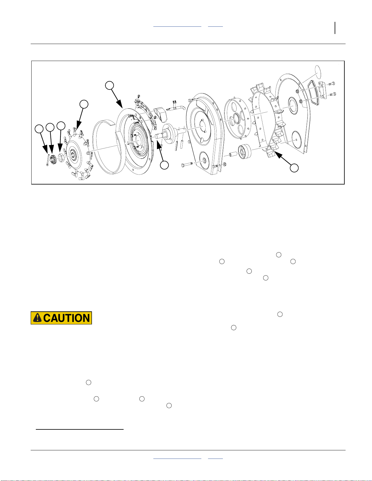
Great Plains Manufacturing, Inc. Table of Contents Index Maintenance and Lubrication 91
4
2
5
6
7
3
Figure 114
Finger Meter Assembly
Meter Maintenance
Finger Pickup Meter Maintenance
Finger Set Inspection
Finger sets should be inspected on an annual basis.
After cleaning, carefully inspect the fingers and springs
for wear or other abnormalities that may develop.
Excessive wear may disrupt singulation performance.
Great Plains recommends having the meter service
performed by a recognized professional repair facility,
such as a certified MeterMax®a representative. If you
choose to servicethem yourself, follow these procedures
when installing the finger sets.
See page 70 for meter removal.
Agricultural Chemical Hazard:
Follow material supplier recommendations carefully. Handle
the meter as if it were treated seed. use supplier-recommended
cleaning agents. Any seed treatment build-up inside a meter is
likely to be at a higher concentration than on the actual seed.
Finger Meter Re-Assembly Steps
Refer to Figure 114
1. Be sure the belt is oriented as shown in
Figure 114.
2. Slide the finger set over the shaft and rotate
clockwise until it sits against the backing plate .
1
2 3
4
1
22507
3. One click will sound when the holder engages the
roll pin and a second click will sound when the cam
engages the bearing housing.
4. Firmly press the finger set against the backing
4 5
plate while tightening the nut .
5. Tighten the nut until contact is made between the
nut and the finger set . Turn1⁄4to1⁄2 flat
(1⁄24to1⁄12 of a turn) (a flat is one of the six sides of
the nut) after contact is made. See page 96 for
details. This equals about 0.45 N-m (4 inch-pounds)
of torque on the nut.
6. Place the slotted nut cover on and carefully align
the slotted nut cover with the shaft hole. Insert the
cotter pin .
7. Rotate the finger set clockwise and make sure the
fingers open and close properly. Rotate the meter
and make sure the meter turns freely and that there
is no air gap between the outer rim of the ashtray
and the backing plate. Fingers should be closed at
the 8:00 to 2:00 position (exit hole) and open at the
2:00 to 8:00 position.
Precautions
Visually check that thereis novisible airgap between the
holder and backing plate.
Make sure the finger set is properly torqued against the
backing plate. Improperly torquedfinger setsmay disrupt
seed singulation.
5
7
2
2
6
a. MeterMax® is a registered trademark of Precision Planting®, Inc.
2014-09-09 Table of Contents Index 401-312M
Page 96

92 3PYP Table of Contents Index Great Plains Manufacturing, Inc.
Population Max™ Annual Maintenance.
Population Max™a insert should be inspected annually.
Inspect plate for wear or other abnormalities that may
develop. The action site area might also eventually
show some wear. When signs of wear appear, simply
replace insert.
Make sure transition between the Population Max™
backing plate and the insert is smooth. A slight incline
from backing plate to insert (clockwise motion) may
cause seeds to catch. Readjust insert if necessary.
Be cautious in using seed treatments, additives, and
other chemicals. They can cause meter performance
problems, premature wear to meter parts, and may
cause undesired chemical reactionor deteriorationto the
Population Max™ material.When using seedtreatments
always use graphite.
If Population Max™ plates are not installed in meter,
store in a vertical position on a cylindrical rod or face to
face.
Population Max™ Installation
Refer to Figure 115
1. Remove brush screws and brush. Gently pull
1
insert out.
2. Select appropriate insert and carefully slide into the
window. Insert may catch on a finger or two. It may
be necessary to lift the fingers up with a small
screwdriver or rotate the fingers backward while
sliding insert in. Insert will slide in without any
unnecessary force.
3. Make sure insertslides in allthe way and firmlylocks
in place.
4. Secure insert to backing plate by fastening the two
screws through the insert.
5. Reinstall brush and screws . Be careful! Do not
tighten brush too tightly or plastic lip may crack.
2
3
4
4
2
4
Figure 115
Population Max™ Insert
3
1
4
24031
a. Population Max™ is a trademark of Precision Planting, Inc.
401-312M Table of Contents Index 2014-09-09
Page 97

Great Plains Manufacturing, Inc. Table of Contents Index Maintenance and Lubrication 93
Skip Stop™ Annual Maintenance
Skip Stop™a should be inspected on an annual basis.
Inspect cushion forwear,pockets, or otherabnormalities
that may develop. Excessive wear or pocket formation
may cause seeds to become trapped and disrupt
1
5
7
singulation performance. As a general rule, if there is a
pocket that is large enough to hold one or more seeds
after the belthas passedby,Skip Stop™ Cushion should
be replaced.
Skip Stop™ Installation
Refer to Figure 116
1. Remove back metal cover by removing five bolts.
Four bolts attach cover to metal housing and one
2 4 3
bolt holds idler wheel and bushing .
2. Align new Skip Stop™ metal cover over
housing .
1
6
1
6
Note: Skip Stop™ metalcover has a hole cut out for
Skip Stop™Cushion . Make sure idler wheel
and bushing remain properly aligned and insert
1
⁄4×2 inchbolt . Secure bolt loosely.
3
2
7 4
4
2
3
Figure 116
Skip Stop™
8
6
24032
3. Insert remaining three1⁄4×1⁄2inch bolts to fasten
metal cover to housing. Tighten all bolts securely.
4. Tighten bolt that secures idler wheel and turn belt
via the bearing shaft by hand to verify that belt is
centered between housing. If necessary, loosen bolt
and slide cover to adjust and re-center belt.
5. Place Skip Stop™ Cushion over the opening.
Insert two1⁄4×3⁄4inch bolts to secure Skip Stop™
Cushion to housing.
2
Meter Performance Risk:
Make sure Skip Stop™ Cushion is secured tightly to back
7
metal cover and cannot turn or rotate. Make sure Skip Stop™
7
7
Cushion does not interfere with belt rotation in any
manner. A loose Skip Stop™ Cushion may result in seed
leakage, poor meter performance, and planting errors.
7 5
7
a. Skip Stop™ is a trademark of Precision Planting, Inc.
2014-09-09 Table of Contents Index 401-312M
Page 98

94 3PYP Table of Contents Index Great Plains Manufacturing, Inc.
Exchanging Finger Sets
Althoughtime-consuming, cornmeters maybe, with care,
converted to sunflower meters, and vice-versa
with factory-supplied corn meters,order quantity16 of:
403-659A SUNFLOWER 12 FINGER CONV KIT
Refer to Figure 117
This kit contains a sunflower finger set , Insert C
and brushless block .
Note: Meter conversion isavailableonly for finger pickup
meters that were originallycorn meters.
Factory-supplied sunflower meters cannot be
converted to corn meters,as they lack a brush
adjustment decal, which requires a factory
alignment fixture.
3
Remove Meter Cover
1. Remove the finger pickup meters from the rows
(page 70).
2. Remove three sets of bolts and nuts securing the
cover to the meter.
a
. Starting
1 2
3
1
Figure 117
Sunflower Conversion Kit
7
6
2
34530
Remove Adjustment Lever
Refer to Figure 118
3. Remove the E-clip closer to the brush block .
4. Withdrawthe adjustment lever . Store the removed
e-clip on it.
Note: Sunflower meters use a brushless block(installed
at step 13). Thebrushless block cannot be
installed with the adjustment leverpresent.
6 7
7
Remove Brush Block
5. Remove the two screws that secure the brush
7
block , then remove the brush block.
9
9
9
Figure 118
Remove Adjustment Lever
8
34527
a. Larger sunflower sizes plant with the standard Corn configuration. See “Sunflower Meter Configurations” on page 75.
401-312M Table of Contents Index 2014-09-09
Page 99

Great Plains Manufacturing, Inc. Table of Contents Index Maintenance and Lubrication 95
Remove Corn Finger Set
Refer to Figure 119
6. Straighten and remove the cotter pin .
7. Remove the nut cover .
8. Remove the nut .
9. Remove the corn finger set .
2
3
4
1
3
4
2
1
Remove Insert “A”
Refer to Figure 120
10. Remove the two screws that secure the Insert
to the backing plate.
11. Lift the insert out of the backing plate.
5 6
Install Insert “C”
12. Select a meterinsert from the conversion kit. Inspect
the back for a legend identifying it as “C”. Install it in
the backing plate. Secure with screws .
5
Install Brushless Block
13. Select a brushless block from the conversion kit.
This block, in additionto havingno brushes,also has
a single mounting screw hole (the removed brush
block has two holes).
Install the block as shown, using one screw through
the center outer hole in the backing plate.
Note: Do notre-install theadjustment lever. Itis notused
with sunflower meters.
7
8
Figure 119
Remove Corn Finger Set
5
6
5
Figure 120
Remove/Install Meter Insert
7
34528
34529
8
Figure 121
Install Brushless Block
2014-09-09 Table of Contents Index 401-312M
34531
Page 100

96 3PYP Table of Contents Index Great Plains Manufacturing, Inc.
Install Sunflower Finger Set
Refer to Figure 122
14. Select the finger set from the conversion kit.
Sunflower fingers have short square “flags” at the
ends of the fingers, compared to corn finger sets,
which have longer rounded flags.
1
5
3
Place the finger set on the meter shaft. Rotating the
finger set and shaft as needed, seat the finger set
fully against the back plate. There should be no air
gap between the hub rim and the backing plate.
4
2
1
The shaft cross-pin seats in deep detents in the
finger set hub. The bearing housing has a
rectangular notch that engages a rectangular tab
projection in the finger set.
Note: If the finger set does not seat fully, this is usually
because the notch and projection are not mated.
Rotate the finger set clockwise until you feel two
clicks.Thefingersshould dipintothe seed dropexit
port, then lift, withoutcatching on the backing plate.
15. Select the nut from step 8. Spin it onto the shaft. Do
not tighten at this step.
5
2 3
4
Set Finger Set Torque
Refer to Figure 123
16. Loosen the nut .
Press the finger sethub firmlyagainst the back plate,
checking that it is fully seated and has no wobble.
Turn thenut until it contacts the finger set hub(this is
the nut position shown as a dashed hexagon in the
upper right illustration).
Tighten the nut by1⁄2to3⁄4of a nut “flat” (this is the
nut position shown as a solid hexagon). This equals
about 0.45 N-m (4 inch-pounds) of torque on the nut.
Refer to Figure 122
17. Place the nut cover on the shaft, making sure to
align it so that the shaft pinhole is not obscured bya
castellation.
18. Insert the cotter pin , but do not secure it.
19. Verify that the finger set turns with aslight amount of
resistance, and that the fingers operate correctly.
Every finger flag must be closed between 8:00 and
2:00 o’clock, and open between 2:00 and 8:00.
20. Secure the cotter pin.
21. Reinstall the meter cover. Reinstall the meter
(page 73).
6
7
8
8
Figure 122
Install Sunflower Finger Set
Field Results and Equipment Damage Risks:
Set the nut torque only as specified. If the
nut is too loose, doubles result during
seeding. If the nut is too tight, it creates
excess drag on the drive system, and the
finger set hub wears out prematurely.
Figure 123
Set Torque
6
7
34530
34532
34534
34533
401-312M Table of Contents Index 2014-09-09
 Loading...