

Great Plains 3PNG15 Operator Manual
Operator Manual
3PNG12 and 3PNG15
3-Point Native Grass Drills
Manufacturing, Inc.
www.greatplainsmfg.com
Read the operator’s manual entirely. When you see this symbol, the subsequent
instructions and warnings are serious - follow without exception. Your life and
!
the lives of others depend on it!
22521
Cover illustration may show optional equipment not supplied with standard unit.
© Copyright 2008 Printed 10/06/2008 202-553M


Great Plains Manufacturing, Inc.
Table of Contents
Important Safety Information............................ 1
Safety Decals ...............................................................5
Introduction ........................................................ 9
Description of Unit ........................................................9
Intended Usage ........................................................9
Models Covered .......................................................9
Document Family......................................................9
Using This Manual........................................................9
Definitions.................................................................9
Owner Assistance ......................................................10
Preparation and Setup..................................... 11
Initial Setup.................................................................11
Pre-Planting Setup .....................................................11
Pre-Setup Checklist................................................11
Hitching Tractor to Drill...........................................12
Hydraulic Connections (Marker Option) .............12
Electrical Connections (Option) ..........................12
Gauge-Wheel Adjustment ..................................12
Operating Instructions .................................... 13
Pre-Start Checklist .....................................................13
Drill Lift/Lower.............................................................13
Transporting ...............................................................14
Typical 3PNG12 and 3PNG15 Weights by Configu-
ration...............................................................14
Loading Seed .............................................................15
Main Seed Box Loading .........................................15
Loading Native Grass Box......................................15
Loading Small Seeds Box ......................................15
Seed Rates Overview.................................................16
Seeding Depth Overview............................................16
Acremeter Operation ..................................................17
Normal Operating Sequence..................................17
Dormant Display .................................................17
Field Operation...........................................................18
Marker Operation .......................................................18
Shaft Monitor Operation .............................................19
Parking .......................................................................19
Storage.......................................................................20
Adjustments......................................................21
Seed Rate .............................................................. 21
Planting Depth........................................................ 21
Calibration Overview.................................................. 22
Calibrate with Drill Raised ...................................... 22
Calibrate for
1
/10th Acre or Hectare....................... 22
Calibration Crank Storage...................................... 22
Using Calibration Crank ......................................... 22
Calibration Rotations.......................................... 22
Marker Adjustments ................................................... 23
Marker Disk Angle.................................................. 23
Marker Speed......................................................... 23
Folding Speed with Needle Valves .................... 23
Leveling Drill .............................................................. 24
Gauge-Wheel Adjustment ...................................... 24
Row Unit Adjustments................................................ 25
Disc Blade Adjustments ......................................... 26
Adjusting Disc Contact ....................................... 26
Opener Adjustments .................................................. 27
Opener Down Pressure.......................................... 27
Disc Scraper Adjustment........................................ 27
Seed-Lok™ Lock-Up.............................................. 28
Opener Depth (Press Wheel Height) .....................28
Troubleshooting ...............................................29
Maintenance and Lubrication..........................31
Maintenance .............................................................. 31
Marker Shear Bolt ...................................................... 32
Seed Clean-Out ......................................................... 32
Main Box Clean-Out............................................... 32
Native Grass Box Clean-Out.................................. 33
Small Seeds Box Clean-Out ..................................33
Disc Maintenance................................................... 33
Opener Disc Replacement ................................. 33
Chain Maintenance .................................................... 34
Chain Slack ............................................................ 34
Seed Flap Replacement ............................................ 34
Lubrication ................................................................. 35
© Copyright 2004, 2005, 2006, 2008. All rights Reserved.
Great Plains Manufacturing, Inc. providesthis publication “as is” without warranty of any kind, eitherexpressed or implied. While every precaution has been taken in the preparation
of this manual, Great Plains Manufacturing, Inc. assumes no responsibility for errors or omissions. Neither is any liability assumed for damages resulting from the use of the information contained herein. Great Plains Manufacturing, Inc. reserves the right to revise and improve its products as it sees fit. This publication describes the state of this product at
the time of its publication, and may not reflect the product in the future.
The following are trademarks of Great Plains Mfg., Inc.: Application Systems, Ausherman, Land Pride, Great Plains
All other brands and product names are trademarks or registered trademarks of their respective holders.
10/06/2008 202-553M
Great Plains Manufacturing, Incorporated Trademarks
Printed in the United States of America.

3PNG12 and 3PNG15 Great Plains Manufacturing, Inc.
Options..............................................................37
Accessory Hitches ..................................................... 37
Hitch Setback Kit........................................................ 37
Markers ...................................................................... 38
Seed Tube Plug (Main Seeds)................................... 38
Shaft Monitor.............................................................. 38
Seed Lubricants ..................................................... 39
Small Seeds Attachment............................................ 39
Seed Tube Plug (Small Seeds).............................. 39
Removable Partition............................................... 40
Carbide Disc Scraper................................................. 40
Seed Firmers ............................................................. 40
Seed-Lok® Seed Firmer ........................................ 40
Press Wheels............................................................. 41
Acremeter .................................................................. 41
Appendix A....................................................... 42
Specifications and Capacities.................................... 42
Torque Values ........................................................... 43
Tire Inflation Chart ..................................................... 43
Hydraulic Diagram ..................................................... 44
Appendix B....................................................... 45
Initial Marker Setup (Option)...................................... 45
Terminate Marker Hoses ....................................... 45
Charge Hydraulic System ...................................... 45
Marker Extension Setup ........................................ 45
Marker Extensions ............................................. 46
Marker Extension Adjustment................................ 46
Scraper Installation ................................................ 47
Warranty .................................................................... 48
Index ................................................................. 49
202-553M 10/06/2008
Great Plains Manufacturing, Inc. 1
Important Safety Information
Look for Safety Symbol
The SAFETY ALERT SYMBOL indicates there is a
potential hazard to personal safety involved and extra
safety precaution must be taken. When you see this
symbol, be alert and carefully read the message that follows it. In addition to design and configuration of equipment, hazard control and accident prevention are
dependent upon the awareness, concern, prudence and
proper training of personnel involved in the operation,
transport, maintenance and storage of equipment.
Be Aware of Signal Words
Signal words designate a degree or level of hazard seriousness.
DANGER indicates an imminently hazardous situation
which, if not avoided, will result in death or serious injury.
This signal word is limited to the most extreme situations,
typically for machine components that, for functional purposes, cannot be guarded.
WARNING indicates a potentially hazardous situation
which, if not avoided, could result in death or serious
injury, and includes hazards that are exposed when
guards are removed. It may also be used to alert against
unsafe practices.
CAUTION indicates a potentially hazardous situation
which, if not avoided, may result in minor or moderate
injury. It may also be used to alert against unsafe practices.
DANGER
!
WARNING
!
CAUTION
!
!
Prepare for Emergencies
▲ Be prepared if a fire starts
▲ Keep a first aid kit and fire extinguisher handy.
▲ Keep emergency numbers for doctor, ambulance, hospital
and fire department near phone.
Be Familiar with Safety Decals
▲ Read and understand “Safety Decals” on page 5, thor-
oughly.
▲ Read all instructions noted on the decals.
▲ Keep decals clean. Replace damaged, faded and illegible
decals.
10/06/2008 202-553M
911
2 3PNG12 and 3PNG15 Great Plains Manufacturing, Inc.
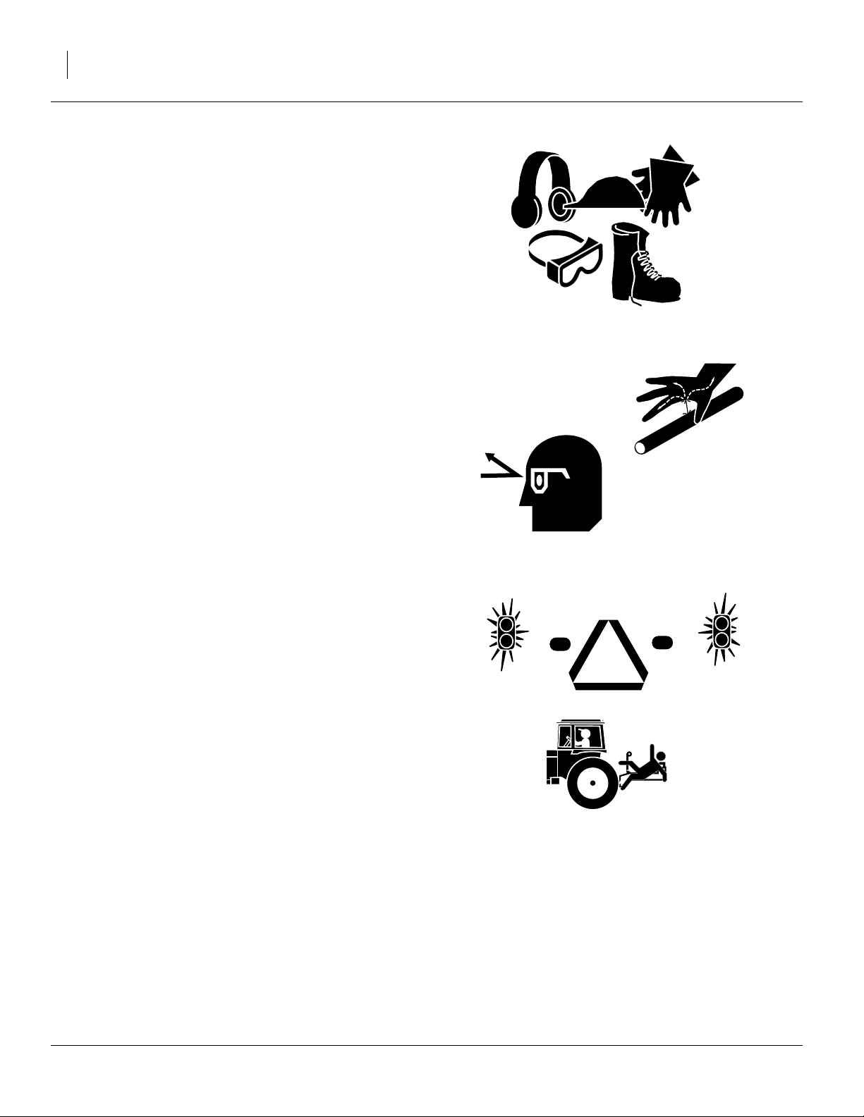
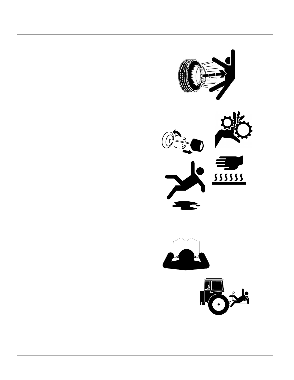
Wear Protective Equipment
▲ Wear protective clothing and equipment.
▲ Wear clothing and equipment appropriate for the job. Avoid
loose-fitting clothing.
▲ Because prolonged exposure to loud noise can cause hear-
ing impairment or hearing loss, wear suitable hearing protection such as earmuffs or earplugs.
▲ Because operating equipment safely requires your full
attention, avoid wearing entertainment headphones while
operating machinery.
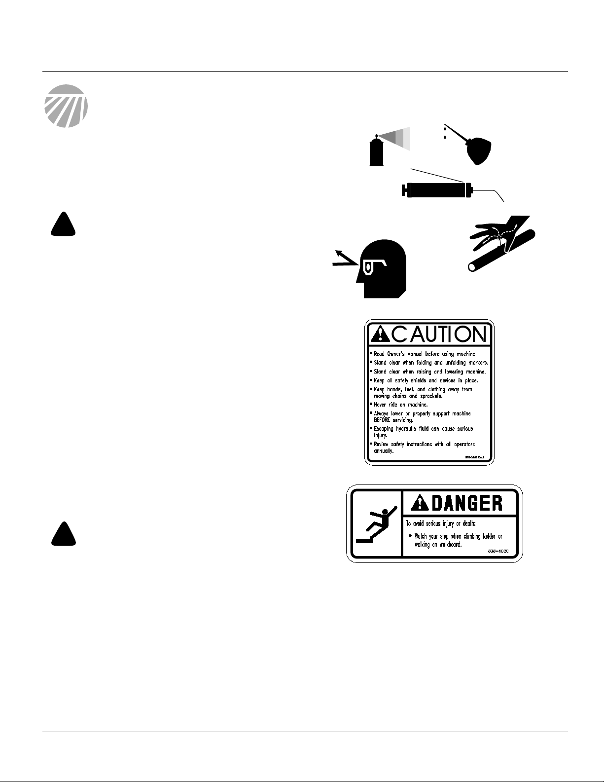
Avoid High Pressure Fluids
Escaping fluid under pressure can penetrate the skin,
causing serious injury.
▲ Avoid the hazard by relieving pressure before disconnecting
hydraulic lines.
▲ Use a piece of paper or cardboard, NOT BODY PARTS, to
check for suspected leaks.
▲ Wear protective gloves and safety glasses or goggles when
working with hydraulic systems.
▲ If an accident occurs, seek immediate medical attention
from a physician familiar with this type of injury.
Use Safety Lights and Devices
Slow-moving tractors and towed implements can create
a hazard when driven on public roads. They are difficult
to see, especially at night.
▲ Use flashing warning lights and turn signals whenever driv-
ing on public roads.
Keep Riders Off Machinery
Riders obstruct the operator’s view. Riders could be
struck by foreign objects or thrown from the machine.
▲ Never allow children to operate equipment.
▲ Keep all bystanders away from machine during operation.
202-553M 10/06/2008
Great Plains Manufacturing, Inc. 3
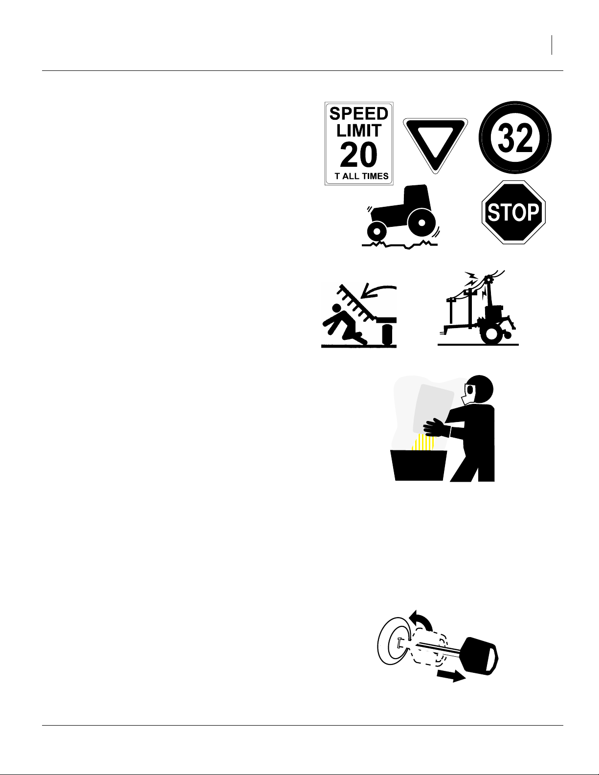
Transport Machinery Safely
Maximum transport speed for implement is 20 mph (32
kph). Some rough terrains require a slower speed. Sudden braking can cause a towed load to swerve and
upset.
▲ Do not exceed 20 mph. Never travel at a speed which does
not allow adequate control of steering and stopping.
▲ Comply with state and local laws.
▲ Do not tow a 3-point implement that, when loaded for
transport, weighs more than the towing vehicle.
▲ Carry reflectors or flags to mark drill in case of breakdown
on the road.
A
Marker Safety
▲ Keep clear of overhead power lines and other obstructions
when transporting. Refer to transport dimensions under
“Specifications and Capacities” on page 42.
▲ Keep all persons well clear of drill during marker opera-
tions.
Handle Chemicals Properly
Agricultural chemicals can be dangerous. Improper use
can seriously injure persons, animals, plants, soil and
property.
▲ Do not use liquid treatments with drill (unless using a fertil-
izer hitch).
▲ Read and follow chemical manufacturer’s instructions.
▲ Wear protective clothing.
▲ Handle all chemicals with care.
▲ Avoid inhaling smoke from any type of chemical fire.
▲ Never drain, rinse or wash dispensers within 100 feet (30m)
of a freshwater source, nor at a car wash.
▲ Store or dispose of unused chemicals as specified by chemi-
cal manufacturer.
▲ Dispose of empty chemical containers properly. Laws gen-
erally require power rinsing or rinsing three times, followed
by perforation of the container to prevent re-use.
Shutdown and Storage
▲ Lower drill, put tractor in park, turn off engine, and remove
the key.
▲ Secure drill using blocks.
▲ Detach and store drill in an area where children normally
do not play.
10/06/2008 202-553M
OFF
4 3PNG12 and 3PNG15 Great Plains Manufacturing, Inc.
Tire Safety
Tire changing can be dangerous and should be performed by trained personnel using correct tools and
equipment.
▲ When inflating tires, use a clip-on chuck and extension hose
long enough for you to stand to one side–not in front of or
over tire assembly. Use a safety cage if available.
▲ When removing and installing wheels, use wheel-handling
equipment adequate for weight involved.
Practice Safe Maintenance
▲ Understand procedure before doing work. Use proper tools
and equipment. Refer to this manual and your Parts Manual
for additional information.
▲ Work in a clean, dry area.
▲ Lower the drill, put tractor in park, turn off engine, and
remove key before performing maintenance.
OFF
▲ Make sure all moving parts have stopped and all system
pressure is relieved.
▲ Allow drill to cool completely.
▲ Disconnect battery ground cable (-) before servicing or
adjusting electrical systems or before welding on drill.
▲ Inspect all parts. Make sure parts are in good condition and
installed properly.
▲ Remove buildup of grease, oil or debris.
▲ Remove all tools and unused parts from drill before opera-
tion.
Safety At All Times
Thoroughly read and understand the instructions in this
manual before operation. Read all instructions noted on
the safety decals.
▲ Be familiar with all drill functions.
▲ Operate machinery from the driver’s seat only.
▲ Do not leave drill unattended with tractor engine running.
▲ Do not dismount a moving tractor. Dismounting a moving
tractor could cause serious injury or death.
▲ Do not stand between the tractor and drill during hitching.
▲ Keep hands, feet and clothing away from power-driven
parts.
▲ Wear snug-fitting clothing to avoid entanglement with mov-
ing parts.
202-553M 10/06/2008

Great Plains Manufacturing, Inc. 5
Safety Decals
Your implement comes equipped with all safety reflectors
and decals in place. They were designed to help you
safely operate your implement.
▲ Read and follow decal directions.
▲ Keep lights in operating condition.
▲ Keep all safety decals clean and legible.
▲ Replace all damaged or missing decals. Order new decals
from your Great Plains dealer. Refer to this section for
proper decal placement.
▲ When ordering new parts or components, also request cor-
responding safety decals.
To install new decals:
1. Clean the area on which the decal is to be placed.
2. Peel backing from decal. Press firmly on surface,
being careful not to cause air bubbles under decal.
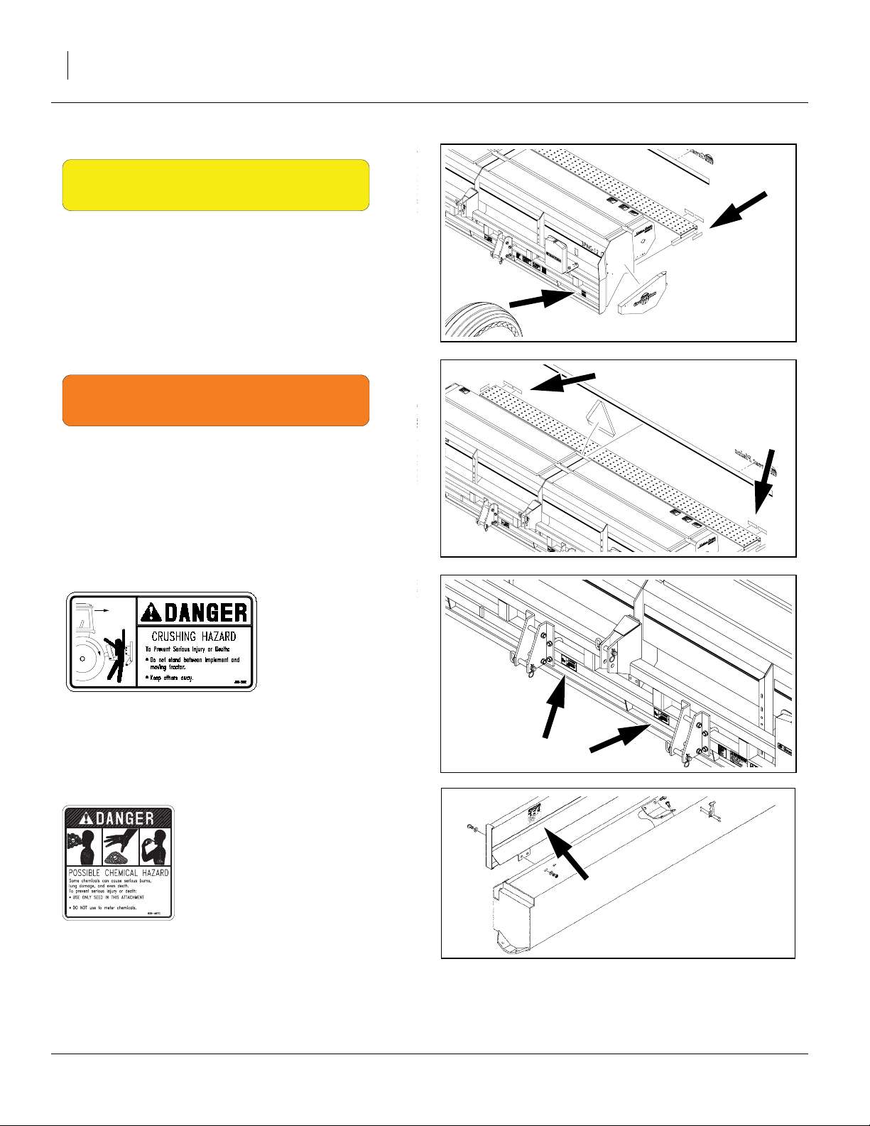
818-003C
Slow Moving Vehicle Reflector
On back of last seedbox, near center;
one total
838-266C
Red Reflectors
Rear face, outside ends of walkboard;
two total
22520
22520
10/06/2008 202-553M
6 3PNG12 and 3PNG15 Great Plains Manufacturing, Inc.
838-265C
Amber Reflectors
Outside ends walkboard,
front face of frame, outside corners,
four total
22520
838-267C
Daytime Reflectors
Rear face walkboard, inboard of red reflectors;
two total
818-590C
Danger: Hitch Crush Hazard
Front of frame, inside each lower hitch point;
two total
22520
22520
838-467C (Option)
Danger: Possible Chemical Hazard
Inside lid of optional Small Seeds boxes;
two total
202-553M 10/06/2008
21730
Great Plains Manufacturing, Inc. 7
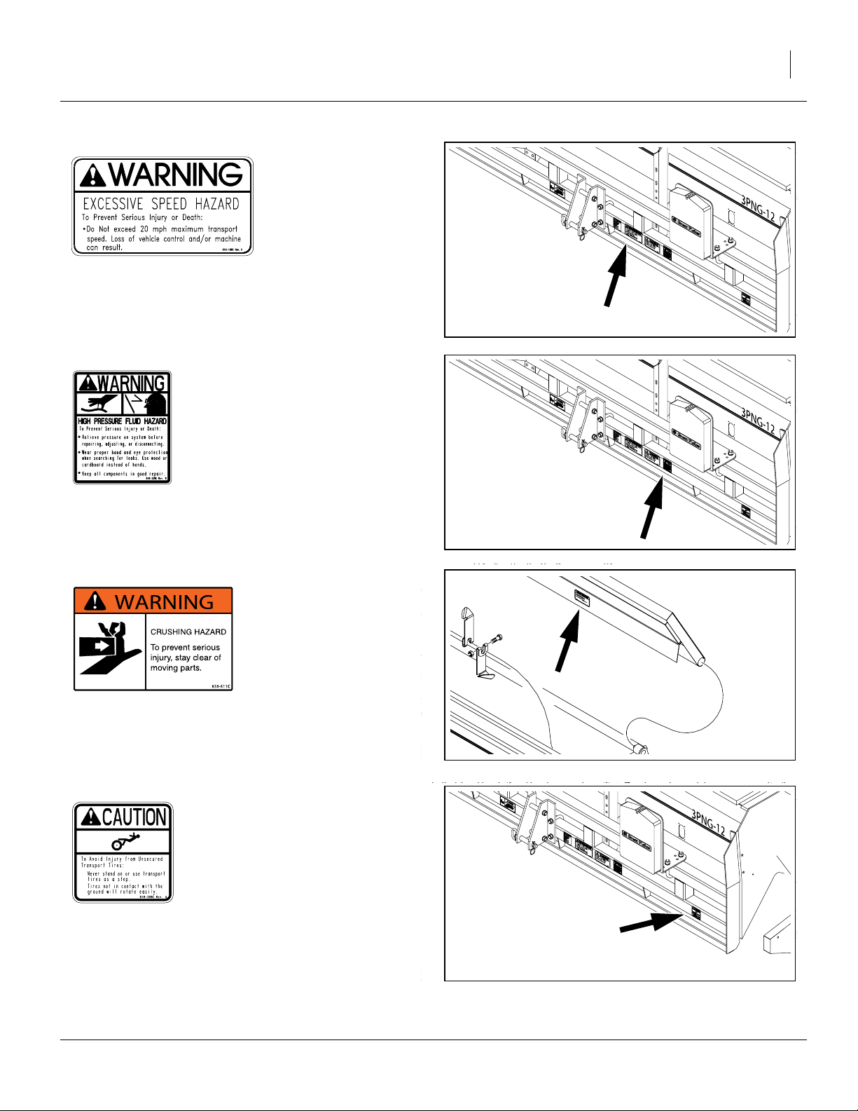
818-188C
Warning: Excessive Speed Hazard
On frame to left of left lower hitch;
one total
22520
818-339C
Warning: High Pressure Fluid Hazard
On frame to left of left lower hitch;
one total
838-611C (Option)
Warning: Hand Crushing Hazard
Inside lid, each Native Grass seed box;
two total
818-398C
22520
28221
Caution: Tires Not a Step
One front frame, outside of each ground drive;
two total
10/06/2008 202-553M
22520
8 3PNG12 and 3PNG15 Great Plains Manufacturing, Inc.
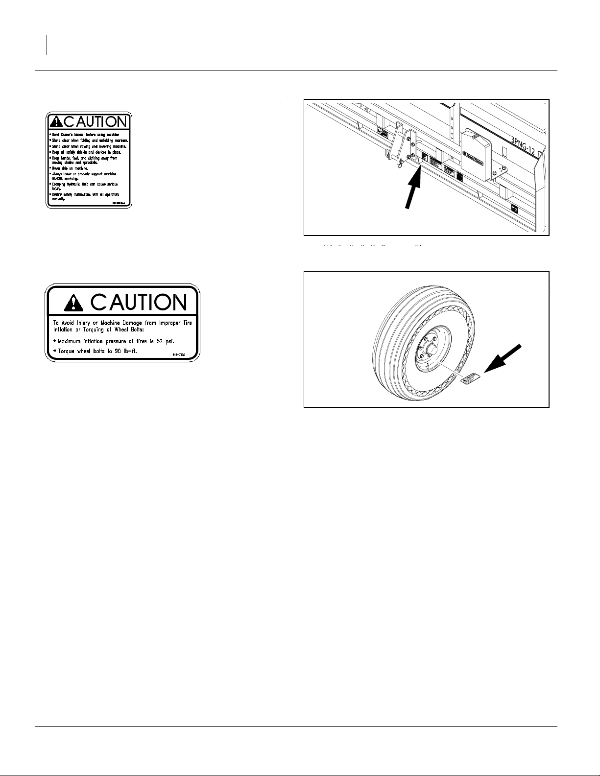
818-587C
Caution: General Instructions
Front frame, left of left lower hitch; one total
818-752C
Caution: Tire Inflation
Outside face of each wheel tire rim; two or four total
22520
22520
202-553M 10/06/2008
Great Plains Manufacturing, Inc. Introduction 9
Introduction
Great Plains welcomes you to its growing family of new
product owners. This drill has been designed with care
and built by skilled workers using quality materials.
Proper setup, maintenance and safe operating practices
will help you get years of satisfactory use from the
machine.
Description of Unit
The 3PNG12 and 3PNG15 is a 12- or 15-foot 3-point
seeding implement designed for seeding grasses and
grass mixes. The drill is equipped with offset double-disk
openers mounted on the drill frame with straight arms.
The openers are staggered for easy residue flow. Downpressure springs can be adjusted individually for each
opener. A T-handle adjustment on the depth-controlling
press wheels allows for easy depth adjustment. The
seeding rate can be adjusted from 2 to 240 pounds per
acre.
When combined with the bedded irrigation option, the
drill can be used to seed in furrows and ridges simultaneously.
Intended Usage
This drill is intended for use in conventional- and some
minimum-till applications.
Models Covered
3PNG12-1410 12-Foot, 14-Row, 10in
3PNG12-1975 12-Foot, 19-Row, 7.5in
3PNG15-1810 15-Foot, 18-Row, 10in
3PNG15-2475 15-Foot, 24-Row, 7.5in
Document Family
202-553M Operator manual (this manual)
202-579B Seed Rate manual (2007+)
202-553B Seed Rate manual (2006-)
202-553P Parts manual
U
R
R
F
D
Figure 1
Model 3PNG12 and 3PNG15
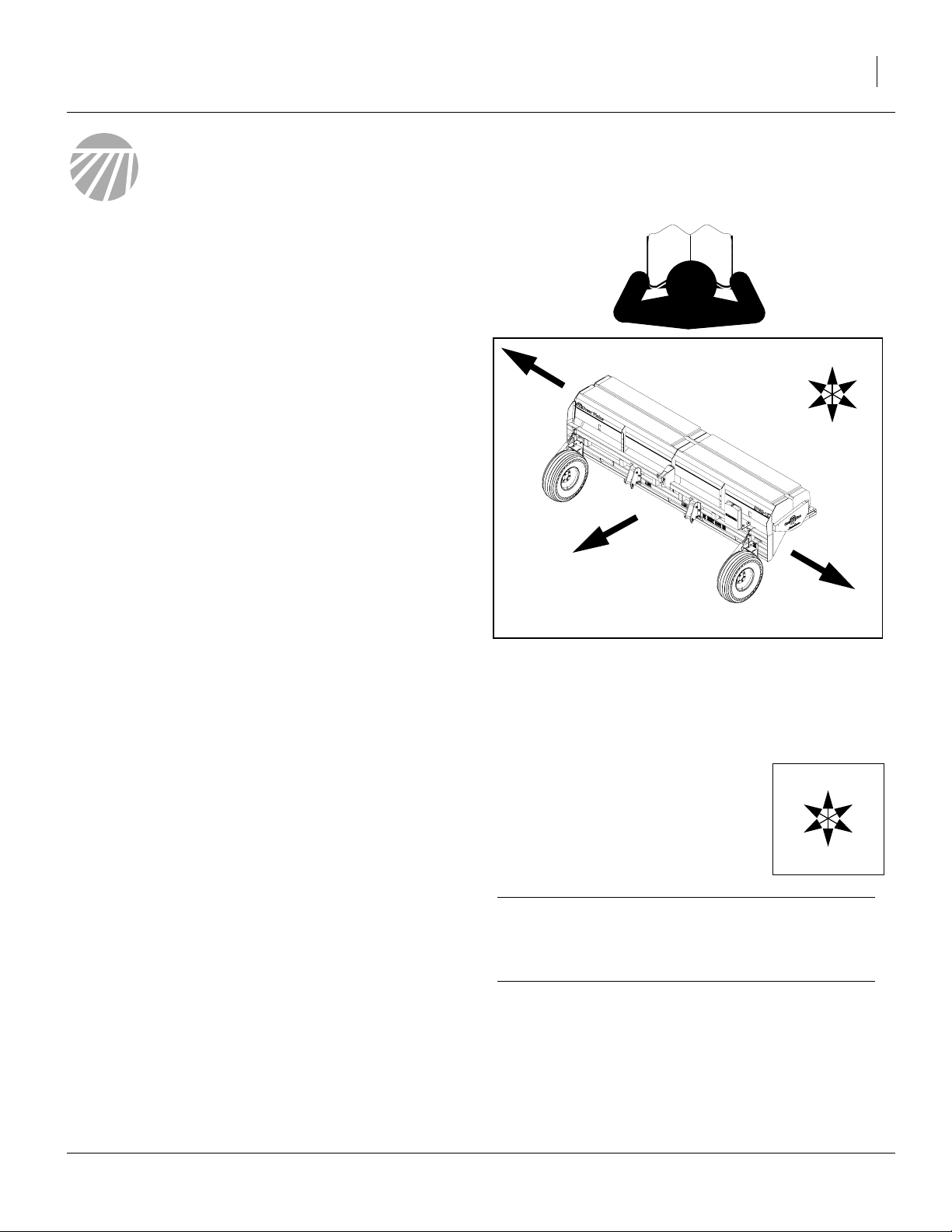
Definitions
The following terms are used throughout this manual.
Right-hand and left-hand as used in
this manual are determined by facing
the direction the machine will travel
while in use unless otherwise stated.
An orientation rose in some line art
illustrations shows the directions of:
Up, Back, Left, Down, Front, Right.
22521
U
R
F
D
B
L
L
B
L
Using This Manual
This manual will familiarize you with safety, assembly,
operation, adjustments, troubleshooting and maintenance. Read this manual and follow the recommendations to help ensure safe and efficient operation.
The information in this manual is current at printing.
Some parts may change to assure top performance.
10/06/2008 202-553M
A crucial point of information related to the preceding
topic. For safe and correct operation, read and follow
the directions provided before continuing.
Note: Useful information related to the preceding topic.
IMPORTANT !
10 3PNG12 and 3PNG15 Great Plains Manufacturing, Inc.
Owner Assistance
If you need customer service or repair parts, contact a
Great Plains dealer. They have trained personnel, repair
parts and equipment specially designed for Great Plains
products.
Your machine’s parts were specially designed and
should only be replaced with Great Plains parts. Always
use the serial and model number when ordering parts
from your Great Plains dealer.
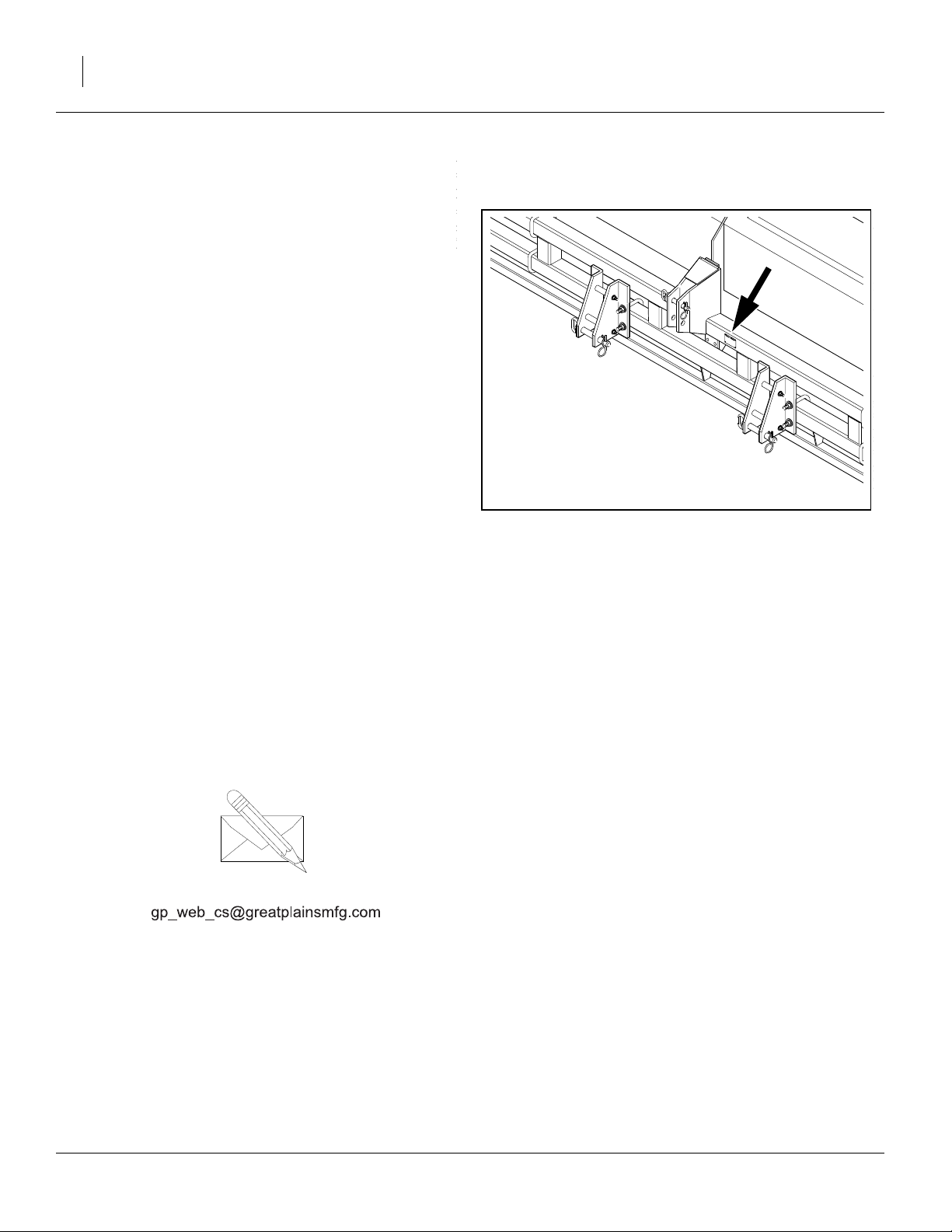
Refer to Figure 2
The serial-number plate is located on the front face of the
frame.
Record your drill model and serial number here for quick
reference:
Model Number:________________________________
Serial Number: ________________________________
Your Great Plains dealer wants you to be satisfied with
your new machine. If you do not understand any part of
this manual or are not satisfied with the service received,
please take the following actions.
1. Discuss the matter with your dealership service
manager. Make sure they are aware of any problems
so they can assist you.
2. If you are still unsatisfied, seek out the owner or general manager of the dealership.
3. For further assistance write to:
Figure 2
Serial Number Plate
16404
Product Support
Great Plains Mfg. Inc., Service Department
PO Box 5060
Salina, KS 67402-5060
785-823-3276
202-553M 10/06/2008

Great Plains Manufacturing, Inc. Preparation and Setup 11
Preparation and Setup
This section helps you prepare your tractor and drill for
use.
Initial Setup
If the drill has just been delivered, or broken down for reshipment, these items need to be completed prior to first
field use:
•“Initial Marker Setup (Option)” on page 45
You may also need to install features, options and accessories that are not factory-installed, such as Markers or
Shaft Monitor.
Pre-Planting Setup
The balance of this section covers items that need to be
completed or checked prior to each field use of the drill.
Pre-Setup Checklist
1. This drill requires a tractor with adequate weight and
a Category II, III or IIIN 3-point hitch.
2. Read and understand “Important Safety Informa-
tion” on page 1.
3. Check that all working parts are moving freely, bolts
are tight, and cotter pins are spread.
4. Check that all grease fittings are in place and lubricated. Refer to “Lubrication” on page 35.
5. Check that all safety decals and reflectors are correctly located and legible. Replace if damaged. See
“Safety Decals” on page 5.
6. Inflate tires to pressure recommended and tighten
wheel bolts as specified. See “Torque Values” on
page 43.
10/06/2008 202-553M
12 3PNG12 and 3PNG15 Great Plains Manufacturing, Inc.
Hitching Tractor to Drill
!
DANGER
You may be severely injured or killed by being crushed
between the tractor and drill. Do not stand or place any part of
your body between drill and moving tractor. Stop tractor
engine and set park brake before installing hitch pins.
7. Raise or lower the 3-point links as needed.
8. Install the lower hitch pins.
9. Pin the top link to the drill and adjust so it remains
loose in normal field conditions.
10. Check that all three-point links are securely pinned,
then slowly raise the drill. Watch for cab interference.
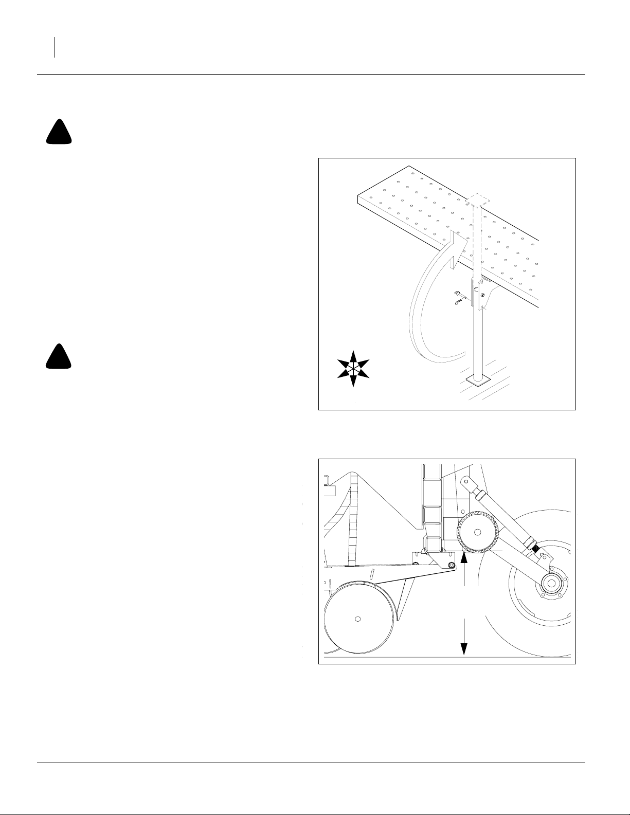
Refer to Figure 3
11. Unpin the parking stands as shown. Rotate the
stands up into field position and re-pin.
Hydraulic Connections (Marker Option)
U
D
F
F
Figure 3
Parking Stand
18
46.4cm
Figure 4
Opener Tool Bar Height
12151
1
⁄
in
4
22546
!
WARNING
Escaping fluid under pressure can have sufficient pressure to
penetrate the skin. Check all hydraulic lines and fittings before
applying pressure. Fluid escaping from a very small hole can
be almost invisible. Use paper or cardboard, not body parts,
and wear heavy gloves to check for suspected leaks. If injured,
seek immediate medical attention from a physician familiar
with this type of injury.
The standard 3PNG12 and 3PNG15 drill does not have
hydraulic circuits. If equipped with marker(s), the drill
requires one remote circuit for each side.
12. Connect each base end hose to an extend port, and
the rod end hose to a retract port.
Electrical Connections (Option)
13. Connect lighting harness.
14. Connect any optional electrical harnesses, such as
shaft monitor.
Gauge-Wheel Adjustment
Gauge-wheel adjustments affect the operating height of
your drill, and drill height directly affects the working
range of the openers.The drill must be adjusted so your
openers can travel up and down and follow the ground
contour.
Refer to Figure 4
15. Before using in the field, with drill level front-to-back,
adjust so the opener mount tube runs 18
above ground. Further adjustments to compensate
for field conditions are likely. See page 24.
1
⁄
inches
4
L
B
202-553M 10/06/2008
Great Plains Manufacturing, Inc. Operating Instructions 13
Operating Instructions
This section covers general operating procedures. Experience, machine familiarity and the following information
will lead to efficient operation and good working habits.
Always operate farm machinery with safety in mind.
Pre-Start Checklist
!
WARNING
Escaping fluid under pressure can have sufficient pressure to
penetrate the skin. Check all hydraulic lines and fittings before
applying pressure. Fluid escaping from a very small hole can
be almost invisible. Use paper or cardboard, not body parts,
and wear heavy gloves to check for suspected leaks. If injured,
seek immediate medical attention from a physician familiar
with this type of injury.
1. Carefully read “Important Safety Information” on
page 1.
2. Lubricate drill as indicated under “Lubrication” on
page 35.
3. Check all tires for proper inflation. See
Chart
” on page 43.
4. Check all bolts, pins and fasteners. Torque as shown
in “Torque Values” on page 43.
5. Check drill for worn or damaged parts. Repair or
replace parts before going to the field.
6. Check hydraulic hoses, fittings and cylinders for
leaks. Repair or replace before going to the field.
7. Rotate each ground drive wheel to see that the
drives and meters are working properly and free
from foreign material.
“Tire Inflation
!
DANGER
Watch your step when walking on drill ladder and walkboard.
Falling from drill could cause severe injury or death.
Drill Lift/Lower
Raising and lowering the drill relies on the tractor 3-point
hitch.
To safely raise the drill, the tractor must weigh more than
the drill, and tractor weight must be distributed so front
tractor wheels remain in solid contact with the ground.
Add weights at tractor front as needed (see page 14).
Lowered position is initially set to 18
as adjusted per page 24. Set a stop or operate the hitch
in Float.
10/06/2008 202-553M
1
⁄
inches (page 12),
4
14 3PNG12 and 3PNG15 Great Plains Manufacturing, Inc.
Transporting
Before transporting with a tractor, check these items:
1. Check that tractor is sufficient for towing the drill
(page 42). Use a tractor with adequate weight relative to drill. See the tables below for typical drill
weights.
You may need to add ballast to the tractor front end.
2. Check that 3-point hitch links are securing pinned to
the tractor.
3. Unload drill boxes. The drill can be transported with
full boxes of material (other than native Grass), but
the added weight increases stopping distance,
reduces steering effectiveness and generally
decreases maneuverability. Unload before transporting if possible.
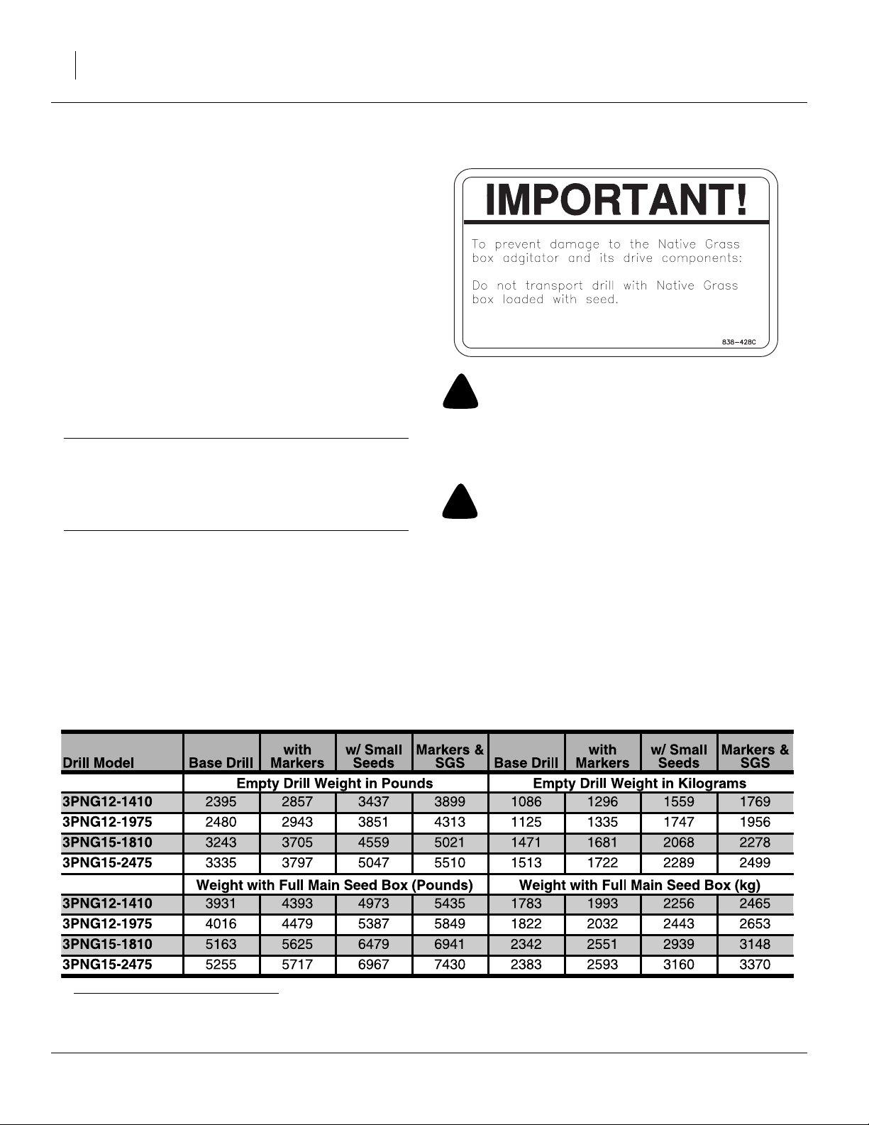
IMPORTANT !
Do not transport with Native Grass box loaded. Heavier
mix components settle to the bottom, which can prevent drive system from operating or cause irregular
seed rate and population distribution.
4. Raise drill completely (page 13).
5. Turn on lights.
Keep Clearance in Mind
Remember that the drill may be wider than the tractor.
Allow safe clearance.
Observe Road Rules
Comply with all national, regional and local safety laws
when traveling on public roads.
!
DANGER
Unstable Load Hazard:
Tow the drill only with a tractor with sufficient power and that
weighs more than the drill, and has ample weight on steering
wheels at all times.
!
WARNING
Excessive Speed Hazard:
Towing the drill at high speeds can lead to loss of vehicle control and a serious road accident, injury and death. To reduce
the hazard, do not exceed 20 mph.
Typicala 3PNG12 and 3PNG15 Weights by Configuration
a. Weights are approximate, and can vary by hundreds of pounds based on material density, press wheel options, accessories and user
modifications. Weight kit figures presume dual markers (vs. single) and dual gauge wheels on 3PNG15.
202-553M 10/06/2008
 Loading...