

Great Plains 3PNG15 User Manual

Manufacturing, Inc.
www.greatplainsmfg.com
Seed, Small Seeds, and Native Grass Rate Charts for 2007+ 3PNG12 and 3PNG15 Native Grass Drills
The following pages are to assist in the proper setting of seeding and fertilizer application rates for the 12ft and 15ft Native Grass 3-Point drills. The
rates indicated in the charts are approximate values. To assure the most
accurate seeding rate it is recommended that the drill be calibrated for the
desired seed at the time of planting.
© Copyright 2007 Printed 12/01/2010 202-579B

3PNG12 & 3PNG15 Great Plains Manufacturing, Inc.
Table of Contents
Introduction ................................................................ 1
Products Covered ........................................................ 1
Document Family ......................................................... 1
Setting Planting Rate ................................................... 1
Main Seed Box Planting ............................................ 2
Main Seed Box Rate .................................................... 2
Setting Drive Type ................................................... 2
Changing Double Sprocket .................................. 3
Changing Jackshaft Sprocket .............................. 3
Main Seed Box Rate Handle.................................... 4
Position Seed Cup Doors......................................... 4
Checking Main Seed Box Rate .................................... 5
Rate Charts, Main Seed Box ....................................... 6
Alfalfa or Rape ..................................................... 6
Barley ................................................................... 6
Buckwheat............................................................ 6
Buffalograss (1 of 4)............................................. 6
Flax or Sudan....................................................... 7
Millet..................................................................... 7
Milo....................................................................... 7
Oats or Safflower ................................................. 7
Peas ..................................................................... 7
Pinto Beans.......................................................... 7
Rice, Short Grain (1 of 2) ..................................... 8
Rice, Long Grain (1 of 2)...................................... 8
Rye....................................................................... 8
Soybeans (1 of 3)................................................. 8
Sunflower ............................................................. 9
Wheat (1 of 2) ...................................................... 9
Wheatgrass .......................................................... 9
Smalls Seeds Box Planting .................................... 10
Small Seeds Box Rate............................................... 10
Small Seeds Drive Type ........................................ 10
Changing Double Sprocket................................ 11
Changing Jackshaft Sprocket ............................ 11
Checking Small Seeds Box Rate............................... 12
Rate Charts, Small Seeds Box .................................. 13
Alfalfa, Red Alsike, Crimson Clover................... 13
Kentucky Bluegrass,
Fescue, Annual Rye Grass ............................ 13
Bermuda, Red Top, Lespedeza Unhulled,
Sercia, Sand, Weeping Love Grass............... 14
Red & Sweet Clover, Lespedeza Hulled............ 14
Orchard Grass ................................................... 14
Millet, Reed Canary ........................................... 14
Ladino Clover, Canary Grass,
Timothy, Canola............................................. 14
Birdsfoot, Trefoil, Sudan .................................... 14
Native Grass Planting ............................................. 15
Series II Native Grass Calibration ............................. 15
Native Grass Calibration Formulas/Example......... 18
Native Grass Box Cup Rates..................................... 19
Model 3PNG12 (12-foot)........................................ 19
Model 3PNG15 (15-foot)........................................ 19
Great Plains Graphite Lubricant: ....................... 19
Seeding Brome Grass
with Native Grass Box ........................................... 20
Brome Native Grass Rates .................................... 22
7.5in Spacing: Model 3PNG12 or 3PNG15 ....... 22
10in Spacing: Model 3PNG15 or 3PNG15 ........ 22
© Copyright 2004, 2006, 2007. All rights Reserved.
Great Plains Manufacturing, Inc. provides this publication “as is” without warranty of any kind, either expressed or implied. While every precaution has been taken in the preparation
of this manual, Great Plains Manufacturing, Inc. assumes no responsibility for errors or omissions. Neither is any liability assumed for damages resulting from the use of the information contained herein. Great Plains Manufacturing, Inc. reserves the right to revise and improve its products as it sees fit. This publication describes the state of this product at
the time of its publication, and may not reflect the product in the future.
The following are trademarks of Great Plains Mfg., Inc.: Application Systems, Ausherman, Land Pride, Great Plains
All other brands and product names are trademarks or registered trademarks of their respective holders.
202-579B 12/01/2010
Great Plains Manufacturing, Incorporated Trademarks
Printed in the United States of America.
Great Plains Manufacturing, Inc. Introduction 1
Introduction
This manual is your guide to drill adjustments for achieving specific seed population targets. Although some
setup/adjustment material herein is repeated from the
Operator’s Manual, you need to be thoroughly familiar
with drill operations and adjustments before applying this
Seed Rate manual and its table data.
Products Covered
3PNG12 12ft 3-Point Native Grass Drill, 2007+
3PNG15 15ft 3-Point Native Grass Drill, 2007+
Document Family
202-553M Operator’s Manual
202-553P Parts Manual
202-579B Seed Rate Charts (this manual)
This manual relies on information found only in your
Operator’s Manual. Have both available when preparing
to plant.
Setting Planting Rate
There are four steps to obtaining the desired number of
seeds per acre:
1. Know the characteristics of the seed.
Consult your seed supplier’s reference documents.
2. Find your settings in the charts:
• Main Seed Box, page 6.
• Small Seeds Box, page 13.
• Native Grass Seeds Box, page 15 (Native Grass
mixes other than Brome require calibration).
3. Set the rate for the seed box in use:
• Main Seed Box, page 2.
• Small Seeds Box, page 10.
• Native Grass Seeds Box, page 15.
4. Check planting rate:
• Main Seed Box, page 5.
• Small Seeds Box, page 12.
• Native Grass Seeds Box, page 15.
The charts are based on original factory tires, and
cleaned, untreated seed of average size and test weight.
Many factors affect field results, including field conditions, foreign material, seed size, seed treatment and tire
pressure. Minor adjustments are likely to be needed.
26253
12/01/2010 202-579B
2 3PNG12 & 3PNG15 Great Plains Manufacturing, Inc.
Main Seed Box Planting
Main Seed Box Rate
Initial seeding rate from the main box is controlled by:
• Drive Type on the ground drive,
• Main box Seed Rate Handle, and
• Seed Cup Door setting
Note: The main seed box rate is unaffected by the Small
Seed Rate Handle and Small Seed/Native Grass
sprocket settings.
Setting Drive Type
Main seed box Drive Type is a ground drive sprocket
combination. There are no sprocket changes at the main
seed box itself.
All necessary sprockets are already on the shafts, and
need only be inverted and/or shifted into place.
2
1
Lower double 20T+35T sprocket.
1
Invert on shaft to change.
Upper single jackshaft sprockets (19T or 39T).
2
Slide aside to change.
Before setting the drive type, rotate the gauge wheels.
Check that seed cups, seed tubes and drives are working properly and free from foreign material.
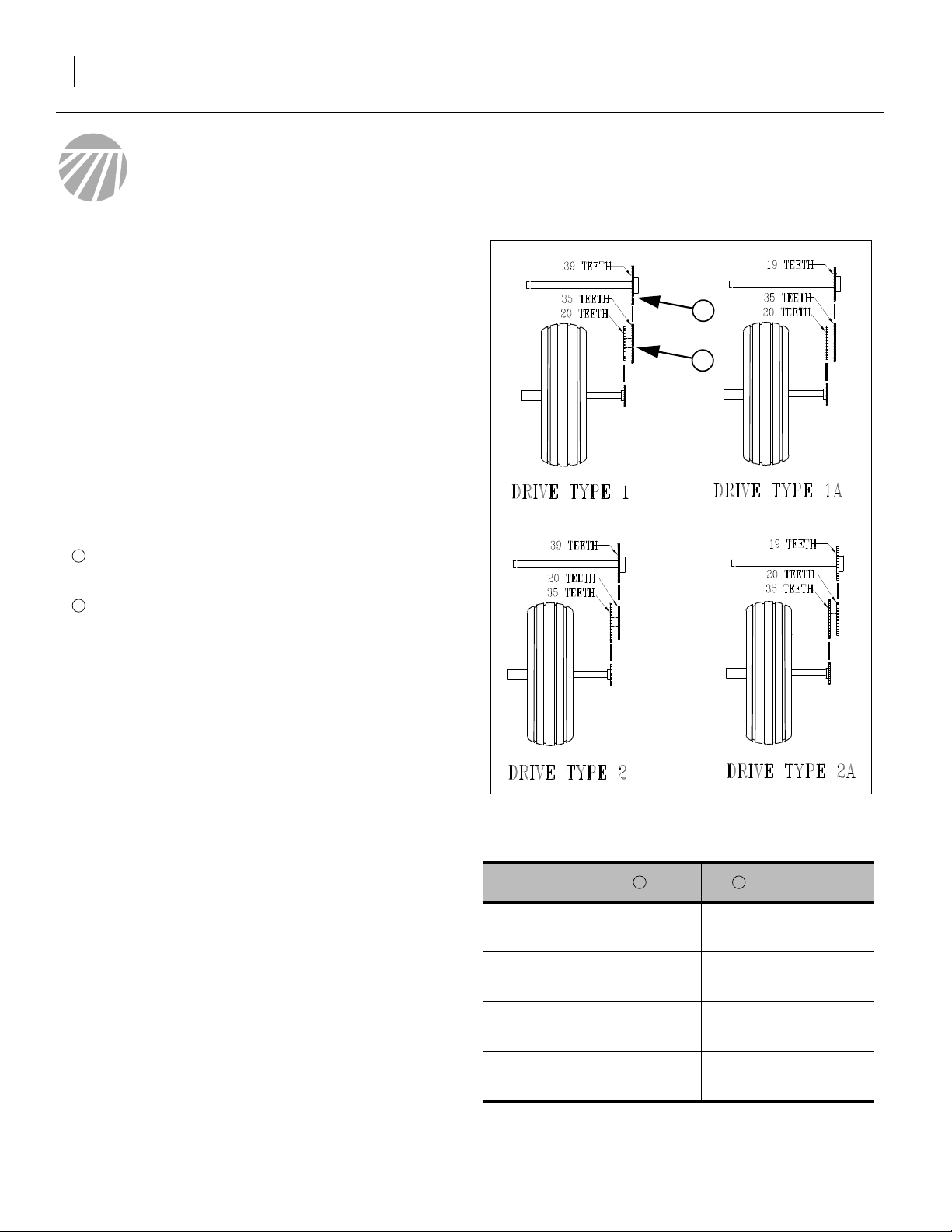
Select the drive type from the seed rate charts. The drive
type varies by seed type and intended population.
Refer to Figure 1
1. Find your drive type in the seed rate charts of this
manual.
2. Find the drive type sprocket set required in Figure 1
or the table at right.
Note: Whether sprockets are changed or not, verify
chain slack, and check that clip openings on
removable links are facing away from the direction
of chain travel.
3. If the double sprocket is already configured as
needed, skip to step 12.
Figure 1
Drive Type Sprockets
Type Speed
Type 1 20T Driven
Type 1A 20T Driven
1 2
35T Driving
35T Driving
39T -
19T 2x Type 1
16400
Type 2 35T Driven
20T Driving
Type 2A 35T Driven
20T Driving
202-579B 12/01/2010
39T
19T
1
⁄
Type 1
3
2
⁄
Type 1
3
Great Plains Manufacturing, Inc. Main Seed Box Planting 3
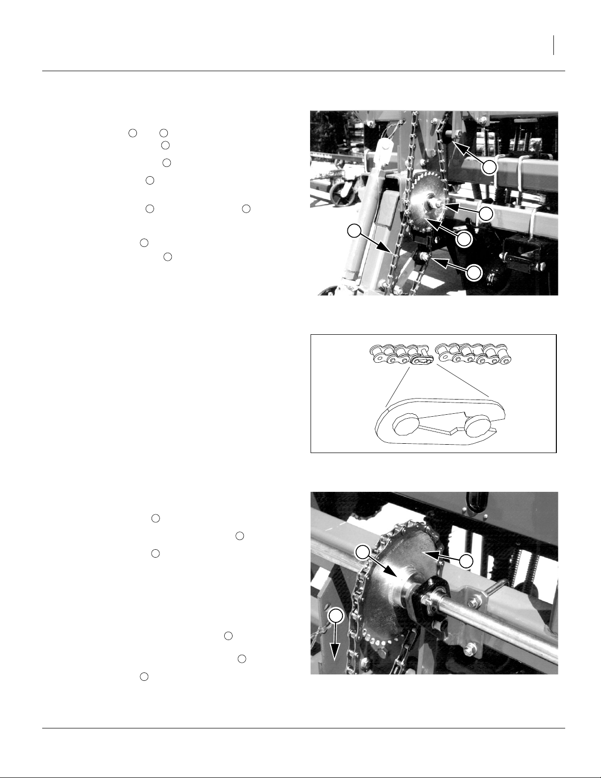
Changing Double Sprocket
Refer to Figure 2
4. Loosen idlers and , and remove both chains
from double sprocket .
3 4
1
5. Remove retaining pin from shaft.
6. Remove sprocket from shaft, and reverse orienta-
5
1
tion of which disk is in/out.
7. Replace sprocket on shaft and re-pin .
1 5
8. Place chains back on sprockets.
9. Re-engage idler and tighten, leaving
forward span of chain .
3
6
3
⁄
in slack in
4
10. If jackshaft sprocket does not need to be changed,
skip to step 17.
Changing Jackshaft Sprocket
It may be necessary to shorten or lengthen the upper
chain. It has removable links for this purpose.
Refer to Figure 3
When re-assembling a chain, make sure the open end of
the clip faces away from the direction of chain travel, to
reduce chain fouling from debris caught in the clip.
3
5
6
1
4
Figure 2
Double Sprocket
16409
Figure 3
26482
Chain Link and Clip
CRefer to Figure 4
11. If the double sprocket did not need to be changed,
loosen upper idler ( in Figure 2).
12. Remove chain from jackshaft sprocket .
13. Loosen set screws on both upper sprockets (only
one of two shown in figure).
3
2
7
7
2
14. Slide current sprocket aside. Position it so that it
does not rub on any fixed machine parts. Re-tighten
the set screw.
15. Slide new sprocket into approximate position.
16. Re-mount chain, and align sprocket so that chain
2
8
is perpendicular to the jackshaft (parallel to the
ground drive frame). Tighten set screw .
17. Re-engage idler and tighten it until there is
3
slack in the forward span.
12/01/2010 202-579B
7
1
⁄
in
2
Figure 4
16412
Jackshaft Sprockets
4 3PNG12 & 3PNG15 Great Plains Manufacturing, Inc.
Main Seed Box Rate Handle
Refer to Figure 5
There is one seed rate handle for the entire main seed
box, located on the left front of the drill above the ground
drive. The seed rate handle controls the percent engagement of the seed sprocket in each seed cup.
1
1
1. Loosen wing nut under handle.
2. Move indicator to about 10 past desired value
from calibration or seed rate chart, then return handle to desired value.
3. Tighten wing nut.
Note: Setting the handle to zero (0) stops all seed flow.
This is useful for making certain row unit adjustments without planting seed.
2
1
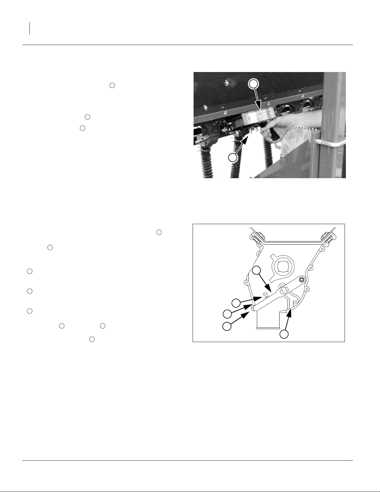
Position Seed Cup Doors
Refer to Figure 6,
which depicts the seed cup door handle in position .
At each seed box seed tube, adjust the seed cup door
handle for the seed size.
The handle has three normal operating position detents:
1
2
3
Note: Handle position is used for cleanout, not plant-
4
(top detent) is for the smallest seeds.
Use it for wheat and similar small seeds.
(middle detent) is for larger seeds.
Use it for soybeans and similar larger seeds.
(bottom detent) is for oversize or fragile seeds.
If you experience excessive cracking with
setting , use setting .
2 3
5
ing. If set to this positionwith seed loaded, it may be
difficult to reset it to a normal operating position.
3
2
Figure 5
Main Seed Box Rate Handle
4
1
2
3
5
Figure 6
Seed Cup Door Handle
17618
26211
202-579B 12/01/2010
Great Plains Manufacturing, Inc. Main Seed Box Planting 5
p
c
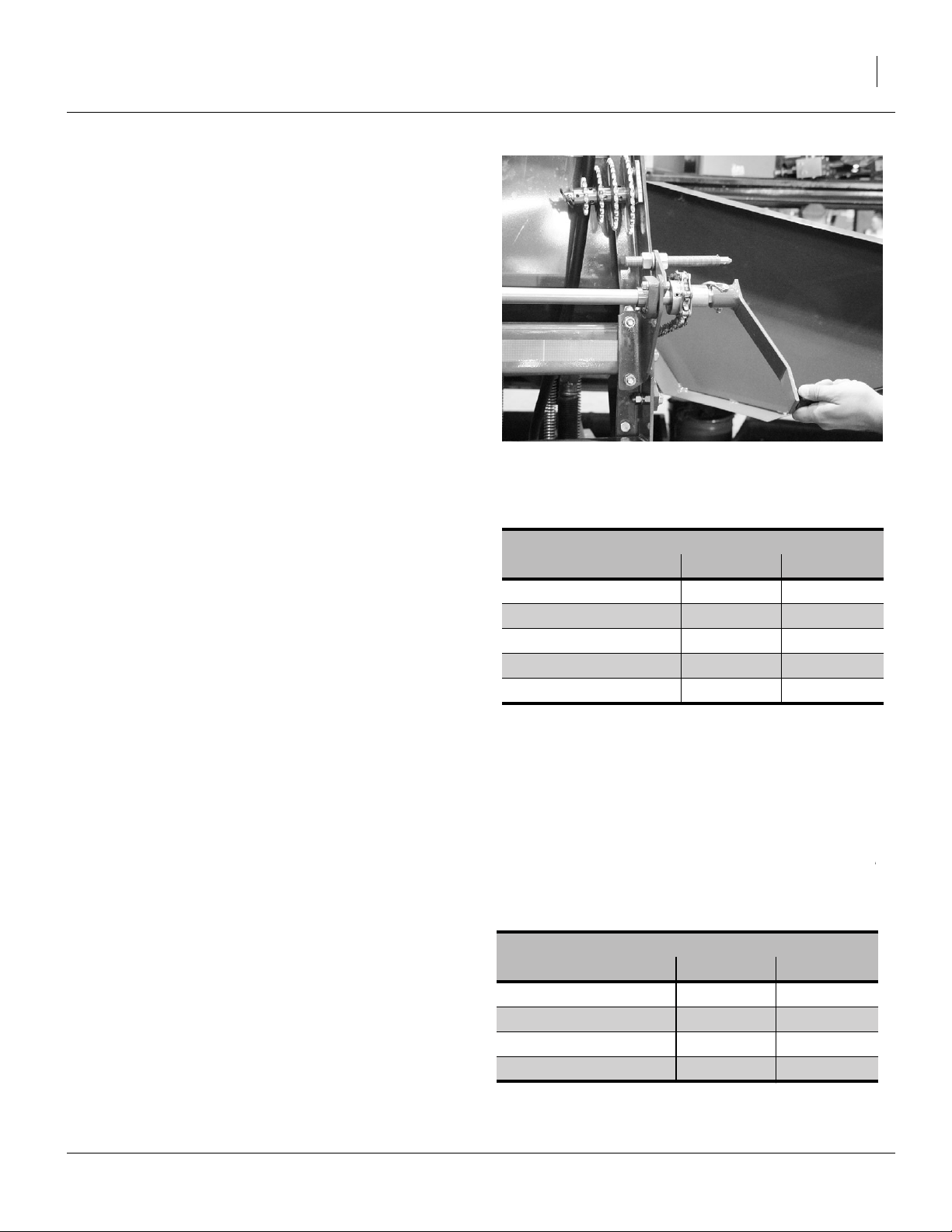
Checking Main Seed Box Rate
1. Set the Drive Type and Seed Rate Handle to the
table value (or leave them at your adjusted value).
2. Record the weight of an empty container large
enough to hold seed metered from the seed box.
3. Raise drill to get drive wheel off the ground. To calibrate using calibration crank, attach crank to upper
jackshaft.
4. Fill three or more compartments at least
seed in the main seed box. Pull seed hoses off open-
ers under the compartments.
Refer to Figure 7
5. To calibrate using calibration crank, disengage
gauge wheel lockout, and attach calibration crank to
coupler on left-hand side of gauge wheel jackshaft
using retaining pin.
1
/
2
full of
Figure 7
3PNG Calibration Crank
and Native Grass Sprockets
23467
6. Turn gauge wheel or crank several times to fill seed
cups with seed. Continue to turn gauge wheel or
crank until seed falls to the ground from each cup.
7. Place the empty container under three seed hoses to
gather the seed as it is metered.
8. Rotate gauge wheel or calibration crank one acre, as
tallied on Acremeter, or as counted based on values
from table at right.
Note: These settings are based on 9.5L-15 tires inflated
to factory specifications.
Note: You can also rotate the gauge wheel jackshaft by
means of a wrench or socket. If rotating gauge
wheel jackshaft, disengage the lockout on the drive
wheel and use same number of rotations as for rotating drive wheel.
9. Check that the three seed cups have plenty of seed
coming into them.
10. Weight metered seed. Subtract initial weight of container. Divide by three.
11. Multiply by the number of openers on the drill to
determine total pounds seeded per acre. If this figure
is different than desired, change your rate handle
and drive type accordingly.
Note: You may want to repeat the calibration proce-
dure if your results vary greatly from seed rate
chart.
Revolutions for One Acre
3PNG12 3PNG15
Crank: Drive Type 1 302 245
Crank: Drive Type 1A 621 502
Crank: Drive Type 2 99 80
Crank: Drive Type 2A 203 164
Gauge Wheel 450 364
easuredSeed EmptyContainer–
----------------------------------------------------------------------------------------- -
undsPerSeedCup NumberOfOpeners× PoundsPerA
Total Row Units
Model Spacing Rows
3PNG12-1410 10 inch 14
3PNG12-1975 7.5 inch 19
3PNG15-1810 10 inch 18
3PNG15-2475 7.5 inch 24
3
PoundsPerSeedCu
=
=
12/01/2010 202-579B
6 3PNG12 & 3PNG15 Great Plains Manufacturing, Inc.
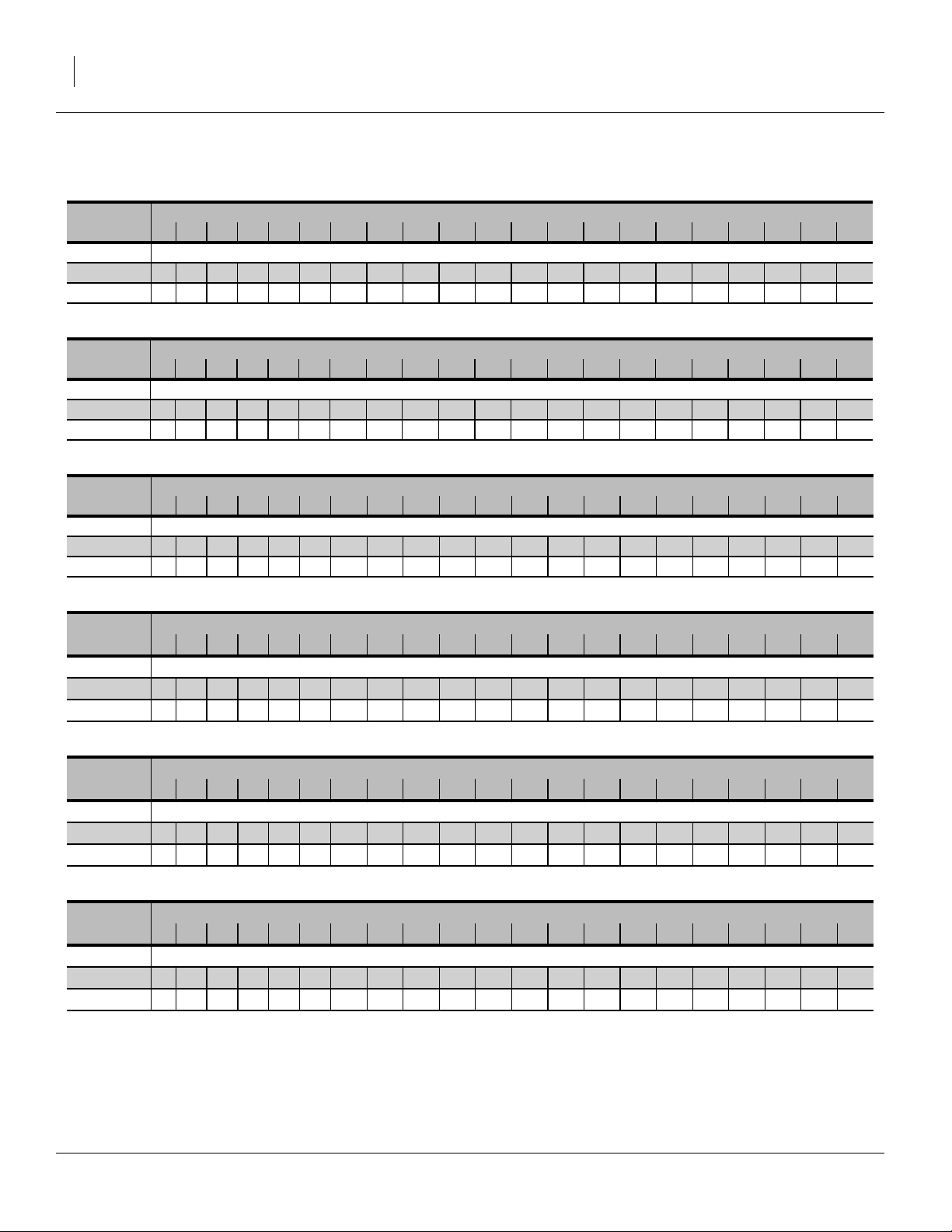
Rate Charts, Main Seed Box
Alfalfa or Rape
Drive Type Seed Rate Handle Setting
2 0 5 10 15 20 25 30 35 40 45 50 55 60 65 70 75 80 85 90 95 100
Rows Seed Rate in Pounds Per Acre (based on 60 pound
7.5 inch 0 3 5 7 9 12 14 16 18 21 23 26 28 30 32 34 36 38 40 41 43
10 inch 0 2 3 5 7 9 10 12 14 16 18 19 21 22 24 25 27 28 30 31 32
Barley
Drive Type Seed Rate Handle Setting
1 0 5 10 15 20 25 30 35 40 45 50 55 60 65 70 75 80 85 90 95 100
Rows Seed Rate in Pounds Per Acre (based on 46.4 pounds/bushel)
7.5 inch 0 0 6 11 16 21 26 31 36 40 44 50 55 60 66 70 75 79 81 84 86
10 inch 0 0 4 8 12 16 20 23 27 30 33 37 41 45 49 53 56 59 61 63 64
Buckwheat
Drive Type Seed Rate Handle Setting
1 0 5 10 15 20 25 30 35 40 45 50 55 60 65 70 75 80 85 90 95 100
Rows Seed Rate in Pounds Per Acre
7.5 inch 0 6 11 16 21 26 32 37 44 50 56 62 68 75 82 89 94 99 102 107 111
10 inch 05 8121520242833374246515661677174778083
s/bushel)
Buffalograss (1 of 4)
Drive Type Seed Rate Handle Setting
2 0 5 10 15 20 25 30 35 40 45 50 55 60 65 70 75 80 85 90 95 100
Rows Seed Rate in Pounds Per Acre
7.5 inch 0 0.1 0.5 1.0 1.6 2.4 3.2 4.1 5.1 6.1 7.1 8.1 9.1 10.1 11.0 11.9 12.7 13.4 13.9 14.4 14.7
10 inch 0 0.0 0.3 0.7 1.2 1.8 3.1 3.8 4.6 5.3 6.1 6.9 7.6 8.3 8.9 8.9 9.5 10.0 10.5 10.8 11.0
(based on 23 pounds/bushel)
Buffalograss (2 of 4)
Drive Type Seed Rate Handle Setting
2A 0 5 10 15 20 25 30 35 40 45 50 55 60 65 70 75 80 85 90 95 100
Rows Seed Rate in Pounds Per Acre
7.5 inch 0 0.1 0.9 2.0 3.3 4.9 6.6 8.5 10.5 12.5 14.6 16.7 18.7 20.7 22.6 24.4 26.0 27.4 28.6 29.5 30.1
10 inch 0 0.1 0.7 1.5 2.5 3.7 5.0 6.4 7.8 9.4 10.9 12.5 14.1 15.6 17.0 18.3 19.5 20.6 21.4 22.1 22.6
(based on 23 pounds/bushel)
Buffalograss (3 of 4)
Drive Type Seed Rate Handle Setting
1 0 5 10 15 20 25 30 35 40 45 50 55 60 65 70 75 80 85 90 95 100
Rows Seed Rate in Pounds Per Acre
7.5 inch 0 0.0 1.4 3.0 5.0 7.3 9.9 12.6 15.6 18.6 21.7 24.9 27.9 30.9 33.8 36.4 38.8 40.9 42.6 44.0 44.8
10 inch 0 0.0 1.0 2.3 3.7 5.5 7.4 9.5 11.7 14.0 16.3 18.6 21.0 23.2 25.3 27.3 29.1 30.7 32.0 33.0 33.6
(based on 23 pounds/bushel)
202-579B 12/01/2010
 Loading...