

Great Plains 3P806NT Operator Manual
Table of Contents Index
Semi-Mounted 8-Foot No-Till Drill
Operator Manual
Model 3P806NT
Manufacturing, Inc.
www.greatplainsmfg.com
Read the operation manual entirely. When you see this symbol, the
subsequent instructions and warnings are serious - follow without
exception. Your life and the lives of others depend on it!
28357
Illustrations may show optional equipment not supplied with standard unit.
ORIGINAL INSTRUCTIONS
© Copyright 2011 Printed 2011-12-20 151-143M
Table of Contents Index
EN

Table of Contents Index
Table of Contents Index

Great Plains Manufacturing, Inc. Cover Index iii
Table of Contents
Important Safety Information ......................................1
Safety Decals .................................................................5
Introduction ................................................................11
Description of Unit ........................................................11
Intended Usage ........................................................11
Models Covered .......................................................11
Using This Manual........................................................11
Owner Assistance ........................................................12
Preparation and Setup ...............................................13
Pre-Delivery Setup .......................................................13
Pre-Planting Setup .......................................................13
Pre-Setup Checklist.................................................. 13
Hitching Tractor to Drill.................................................14
Hydraulic Hose Hookup............................................ 15
Hydraulic Hose Hookup (s/n A1057V+)................ 15
Hydraulic Hose Hookup (s/n A1056V-).................15
Electrical Connection................................................ 15
Leveling the Drill...........................................................16
Stroke Control Spacers (s/n A1057V+) ................17
Check Level..........................................................17
Stroke Control Spacers (s/n A1056V-) .................18
Operating Instructions...............................................19
Pre-Start Checklist .......................................................19
Drill Lift/Lower (s/n A1057V+) ......................................20
Drill Lift/Lower (s/n A1056V-)....................................21
Lowering...................................................................22
Caster Pivot Locks (s/n A1057V+) ...............................23
Caster Pivot Locks (s/n A1056V-) ............................24
Transporting .................................................................25
Semi-Mounted 3-Point Transport .............................25
Typical 3P806NT Weights by Configuration.........26
Trailer Transport.......................................................26
Loading Materials .........................................................27
Main Seed Box Loading ..........................................27
Loading Native Grass Box ....................................... 27
Loading Small Seeds Box .......................................27
Loading Dual Seed Box............................................ 27
Loading Fertilizer......................................................27
Material Rates Overview ..............................................28
Seeding Depth Overview..............................................28
Acremeter Operation ....................................................29
Normal Operating Sequence....................................29
Dormant Display ...................................................29
Field Operation.............................................................30
Parking .........................................................................30
Storage ........................................................................ 30
Adjustments ............................................................... 31
Seed and Fertilizer Rate .......................................... 31
Planting Depth.......................................................... 31
Coulter Adjustments..................................................... 32
Coulter Depth (All Rows).......................................... 32
Coulter Down Pressure ............................................ 33
Available Coulter Force Per Row ......................... 33
Coulter Spring Length .............................................. 33
Coulter Depth (Individual Rows) .............................. 34
Drill Weight Adjustment................................................ 34
Row Unit Adjustments.................................................. 35
Disc Blade Adjustments ........................................... 36
Opener Adjustments .................................................... 37
Opener Down Pressure............................................ 37
Disc Scraper Adjustment.......................................... 37
Small Seeds Tube Adjustment (Option)................... 38
Seed-Lok® Lock-Up ................................................. 38
Opener Depth (Press Wheel Height) ....................... 39
Troubleshooting......................................................... 40
Maintenance and Lubrication ................................... 43
Caster Brake Adjustment ............................................. 44
Caster Brake Adjustment (s/n A1057V+) ................. 44
Pressure Plate Adjustment................................... 44
Caster Brake Adjustment (s/n A1056V-) .................. 45
Materials Clean-Out ..................................................... 46
Main Box and Dual Box Clean-Out .......................... 46
Native Grass Box Clean-Out.................................... 46
Fertilizer Box Clean-Out........................................... 47
Small Seeds Box Clean-Out .................................... 47
Disc Maintenance..................................................... 47
Opener Disc Replacement ................................... 47
Coulter Disc Replacement ................................... 47
Chain Maintenance .................................................. 48
Seed Flap Replacement........................................... 48
Eyebolt Adjustment .................................................. 50
Eyebolt Adjustment (s/n A1057V+) ...................... 50
Eyebolt Adjustment (s/n A1056V-) ....................... 51
Bleeding Hydraulics (s/n A1057V+) .........................52
Lubrication and Scheduled Maintenance..................... 54
Options ....................................................................... 59
Appendix A - Reference Information........................ 65
Specifications and Capacities ...................................... 65
Tire Inflation Chart ....................................................... 65
Torque Values Chart.................................................... 66
© Copyright 2006, 2007, 2008, 2010, 2011 All rights Reserved
Great Plains Manufacturing, Inc. provides this publication “as is” without warranty of any kind, either expressed or implied. While every precaution has been
taken in the preparation of this manual, Great Plains Manufacturing, Inc. assumes no responsibility for errors or omissions. Neither is any liability assumed for
damages resulting from the use of the information contained herein. Great Plains Manufacturing, Inc. reserves the right to revise and improve its products as
it sees fit. This publication describes the state of this product at the time of its publication, and may not reflect the product in the future.
2011-12-20 Cover Index 151-143M
Trademarks of Great Plains Manufacturing, Inc. include: Singulator Plus, Swath Command, Terra-Tine.
Registered Trademarks of Great Plains Manufacturing, Inc. include:
Air-Pro, Clear-Shot, Discovator, Great Plains, Land Pride, MeterCone, Nutri-Pro, Seed-Lok, Solid Stand,
Terra-Guard, Turbo-Chisel, Turbo-Chopper, Turbo Max, Turbo-Till, Ultra-Till, Ver ti-Till, Whirlfilter, Yield-Pro.
Brand and Product Names that appear and are owned by others are trademarks of their respective owners.

iv 3P806NT Table of Contents Index Great Plains Manufacturing, Inc.
Hydraulic Diagrams...................................................... 67
Chain Routing .............................................................. 68
Appendix B - Pre-Delivery......................................... 78
Attach Meter Hoses at Rows ....................................... 86
Appendix C - Accessory Installation........................ 88
Carbide Disc Scraper Installation .................................88
Hitch Extension Installation ..........................................89
Weight Bracket Installation ...........................................90
Warranty ......................................................................91
Index ............................................................................93
151-143M Table of Contents Index 2011-12-20
Great Plains Manufacturing, Inc. Table of Contents Index 1
Important Safety Information
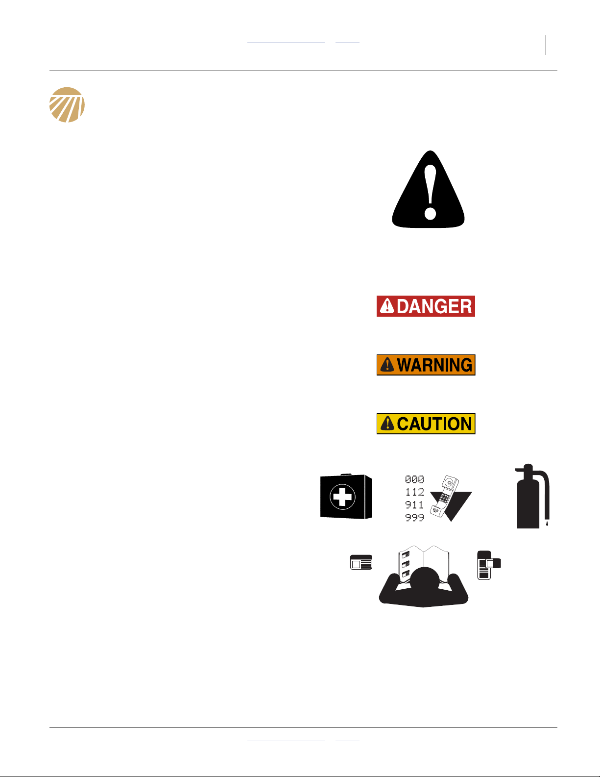
Look for Safety Symbol
The SAFETY ALERT SYMBOL indicates there is a
potential hazard to personal safety involved and extra
safety precaution must be taken. When you see this
symbol, be alert and carefully read the message that
follows it. In addition to design and configuration of
equipment, hazard control and accident prevention are
dependent upon the awareness, concern, prudence and
proper training of personnel involved in the operation,
transport, maintenance and storage of equipment.
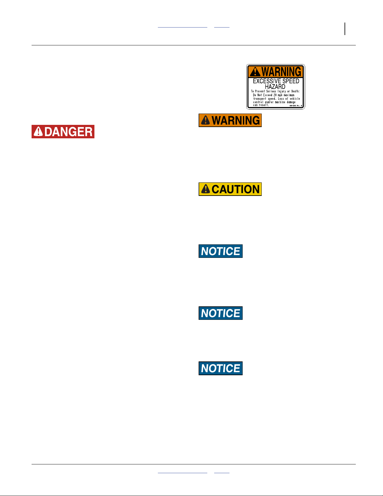
Be Aware of Signal Words
Signal words designate a degree or level of hazard
seriousness.
DANGER, and the color Safety Red, indicate an
imminent hazard which, if not avoided, will result in death
or serious injury. This signal word is limited to the most
extreme situations, typically for machine components
that, for functional purposes, cannot be guarded.
WARNING, and the color Safety Orange, indicate a
potential hazard which, if not avoided, could result in
death or serious injury, and includes hazards that are
exposed when guards are removed. It may also be used
to alert against unsafe practices.
CAUTION, and the color Safety Yellow, indicate a
potential hazard which, if not avoided, may result in
minor or moderate injury. It may also be used to alert
against unsafe practices.
Prepare for Emergencies
▲ Be prepared if a fire starts
▲ Keep a first aid kit and fire extinguisher handy.
▲ Keep emergency numbers for doctor, ambulance, hospital
and fire department near phone.
Be Familiar with Safety Decals
▲ Read and understand “Safety Decals” on page 5,
thoroughly.
▲ Read all instructions noted on the decals.
▲ Keep decals clean. Replace damaged, faded and illegible
decals.
2011-12-20 Table of Contents Index 151-143M

2 3P806NT Table of Contents Index Great Plains Manufacturing, Inc.
Wear Protective Equipment
▲ Wear protective clothing and equipment.
▲ Wear clothing and equipment appropriate for the job. Avoid
loose-fitting clothing.
▲ Because prolonged exposure to loud noise can cause
hearing impairment or hearing loss, wear suitable hearing
protection such as earmuffs or earplugs.
▲ Because operating equipment safely requires your full
attention, avoid wearing entertainment headphones while
operating machinery.
Handle Chemicals Properly
Agricultural chemicals can be dangerous. Improper use
can seriously injure persons, animals, plants, soil and
property.
▲ Do not use liquid seed treatments with the 3P806NT.
▲ Read and follow chemical manufacturer’s instructions.
▲ Wear protective clothing.
▲ Handle all chemicals with care.
▲ Avoid inhaling smoke from any type of chemical fire.
▲ Never drain, rinse or wash dispensers within 100 feet (30m)
of a freshwater source, nor at a car wash.
▲ Store or dispose of unused chemicals as specified by
chemical manufacturer.
▲ Dispose of empty chemical containers properly. Laws
generally require power rinsing or rinsing three times,
followed by perforation of the container to prevent re-use.
Avoid High Pressure Fluids
Escaping fluid under pressure can penetrate the skin,
causing serious injury.
▲ Avoid the hazard by relieving pressure before disconnecting
hydraulic lines.
▲ Use a piece of paper or cardboard, NOT BODY PARTS, to
check for suspected leaks.
▲ Wear protective gloves and safety glasses or goggles when
working with hydraulic systems.
▲ If an accident occurs, seek immediate medical attention
from a physician familiar with this type of injury.
Keep Riders Off Machinery
Riders obstruct the operator’s view. Riders could be
struck by foreign objects or thrown from the machine.
▲ Never allow children to operate equipment.
▲ Keep all bystanders away from machine during operation.
151-143M Table of Contents Index 2011-12-20

Great Plains Manufacturing, Inc. Table of Contents Index Important Safety Information 3
Use Safety Lights and Devices
Slow-moving tractors and towed implements can create
a hazard when driven on public roads. They are difficult
to see, especially at night.
▲ Use flashing warning lights and turn signals whenever
driving on public roads.
▲ Use lights and devices provided with implement
Transport Machinery Safely
Maximum transport speed for implement is 20 mph
(30 kph). Some rough terrains require a slower speed.
Sudden braking can cause a towed load to swerve and
upset.
▲ Do not exceed 20 mph (30 kph). Never travel at a speed
which does not allow adequate control of steering and
stopping. Reduce speed if drill is not equipped with brakes.
▲ Comply with state and local laws.
▲ Carry reflectors or flags to mark drill in case of breakdown
on the road.
▲ Semi-mounted implements reduce weight on steering tires.
Verify that tractor is correctly ballasted. Watch for signs of
poor steering traction.
Tires Not a Step
Do not use gauge wheel or lift-assist tires as steps. A tire
could spin underfoot, resulting in a fall onto the
implement or ground, possibly causing serious injury.
▲ The gauge wheel tire can be in poor ground contact at any
time, even with the drill lowered in the field. It can appear
to be in ground contact, and spin easily, in multiple
conditions.
▲ The lift-assist tires can be in poor ground contact, or out of
ground contact, whenever the drill is lowered.
Shutdown and Storage
▲ Park on level ground.
▲ Secure drill using blocks.
▲ Unhitch and store the drill in an area where children
normally do not play.
Tire Safety
Tire changing can be dangerous and should be
performed by trained personnel using correct tools and
equipment.
▲ When inflating tires, use a clip-on chuck and extension hose
long enough for you to stand to one side–not in front of or
over tire assembly. Use a safety cage if available.
▲ When removing and installing wheels, use wheel-handling
equipment adequate for weight involved.
2011-12-20 Table of Contents Index 151-143M
4 3P806NT Table of Contents Index Great Plains Manufacturing, Inc.
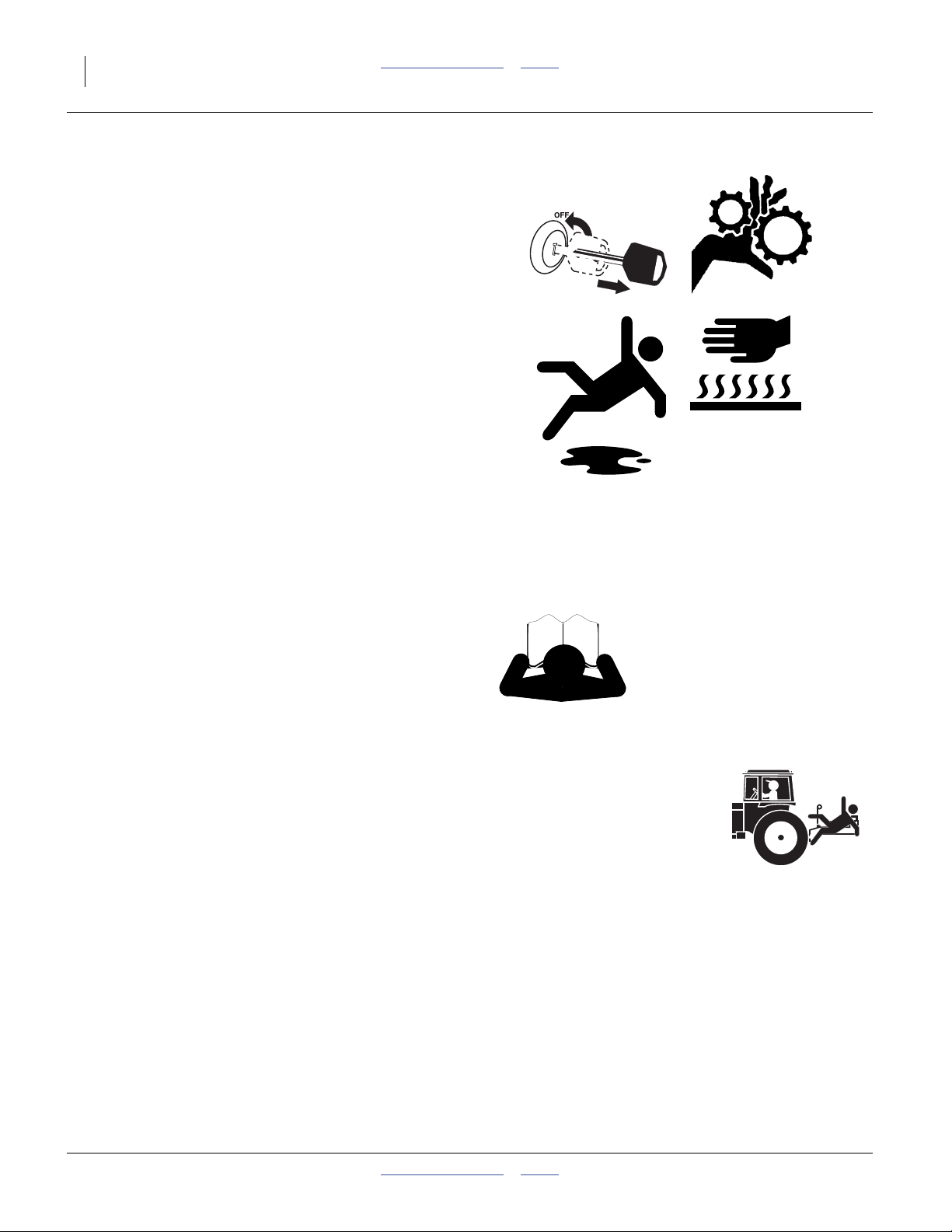
Practice Safe Maintenance
▲ Understand procedure before doing work. Use proper
tools and equipment. Refer to this manual.
▲ Work in a clean, dry area.
▲ Lower the drill, put tractor in park, turn off engine, and
remove key before performing maintenance. If work must
be performed with implement raised, use blocks or
jackstands rated for the drill weight.
▲ Make sure all moving parts have stopped and all system
pressure is relieved.
▲ Allow drill to cool completely.
▲ Disconnect battery ground cable (-) before servicing or
adjusting electrical systems.
▲ Welding: Disconnect battery ground. Avoid fumes from
heated paint.
▲ Inspect all parts. Make sure parts are in good condition
and installed properly.
▲ Remove buildup of grease, oil or debris.
▲ Remove all tools and unused parts from drill before
operation.
Safety At All Times
Thoroughly read and understand the instructions in this
manual before operation. Read all instructions noted on
the safety decals.
▲ Be familiar with all drill functions.
▲ Operate machinery from the driver’s seat only.
▲ Do not leave drill unattended with tractor engine running.
▲ Do not stand between the moving tractor and drill during
hitching.
▲ Keep hands, feet and clothing away from power-driven
parts.
▲ Wear snug-fitting clothing to avoid entanglement with
moving parts.
▲ Make sure all persons are clear of working area.
151-143M Table of Contents Index 2011-12-20
Great Plains Manufacturing, Inc. Table of Contents Index Important Safety Information 5
Safety Decals
Safety Reflectors and Decals
Your implement comes equipped with all lights, safety
reflectors and decals in place. They were designed to
help you safely operate your implement.
▲ Read and follow decal directions.
▲ Keep lights in operating condition.
▲ Keep all safety decals clean and legible.
▲ Replace all damaged or missing decals. Order new decals
from your Great Plains dealer. Refer to this section for
proper decal placement.
▲ When ordering new parts or components, also request
corresponding safety decals.
To install new decals:
1. Clean the area on which the decal is to be placed.
2. Peel backing from decal. Press firmly on surface,
being careful not to cause air bubbles under decal.
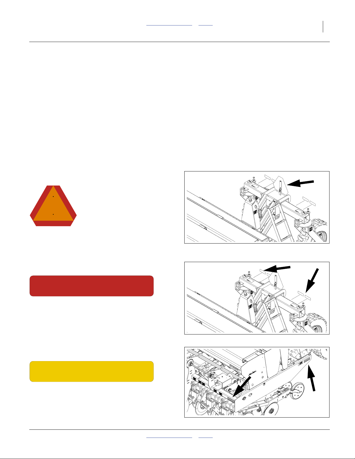
Reflector: Slow Moving Vehicle (SMV)
818-055C
On top of lift assist pivot weldment;
1 total
See “Transporting” on page 25.
Reflectors: Red
838-266C
On rear face of lift assist cross tube, outside daytime
reflectors;
2 total
See “Transporting” on page 25.
32546
32546
Reflectors: Amber
838-266C
On side frames at walkboard ends,
on front face of lower front tool bars, outside ends;
4 total
See “Transporting” on page 25.
2011-12-20 Table of Contents Index 151-143M
32546
6 3P806NT Table of Contents Index Great Plains Manufacturing, Inc.
Reflectors: Daytime
838-267C
On rear face of lift assist cross tube, inside red reflectors;
2 total
See “Transporting” on page 25.
Danger: Moving Chain (Option)
818-518C
DANGER
MOVING CHAIN HAZARD
To prevent serious injury from moving chain:
DO NOT operate with inclosure missing
Dual Seed: On outside of box end wall, under both
covers;
2 total
818 518C
32055
32763
Danger: Moving Chain (Option)
818-518C
DANGER
MOVING CHAIN HAZARD
To prevent serious injury from moving chain:
DO NOT operate with inclosure missing
818 518C
Native Grass: On outside of box end wall, under both
covers;
2 total
Danger: Moving Chain (Option)
818-518C
DANGER
MOVING CHAIN HAZARD
To prevent serious injury from moving chain:
DO NOT operate with inclosure missing
Small Seeds: On chain guard of Small Seeds option;
1 total
818 518C
32760
32610
151-143M Table of Contents Index 2011-12-20
Great Plains Manufacturing, Inc. Table of Contents Index Important Safety Information 7
Danger: Hitch Crush
818-590C
On front face of frame, right of each hitch;
2 total
See “Hitching Tractor to Drill” on page 14.
32546
Danger: Possible Chemical Hazard
838-467C
Under lid of Small Seeds box;
1 total
See “Loading Materials” on page 27.
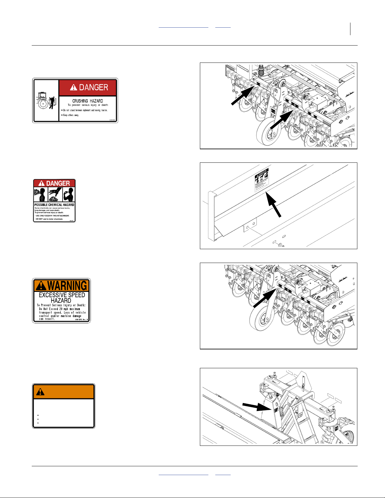
Warning: Speed
818-337C
On front face of upper front cross tube, left of gauge
wheel;
1 total
See “Transporting” on page 25.
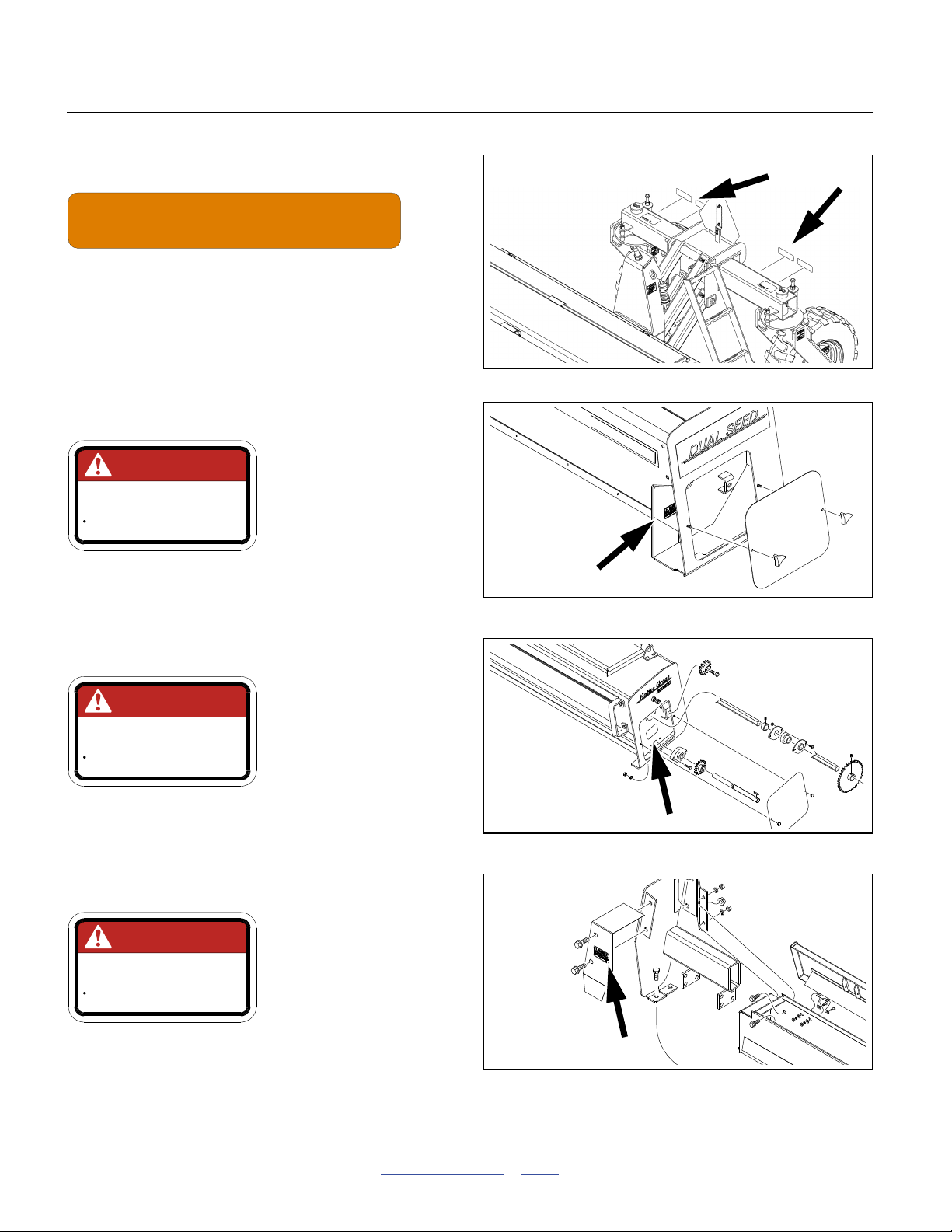
Warning: Transport Locks
838-057C
WARNING
CRUSHING HAZARD
To Avoid Serious Injury or Death,
Install Transport Locks:
Before Performing Maintenance.
Before Adjusting Drill.
Before Transporting.
On left face of lift assist mount weldment;
1 total
838 057C REV
32546
2011-12-20 Table of Contents Index 151-143M
8 3P806NT Table of Contents Index Great Plains Manufacturing, Inc.
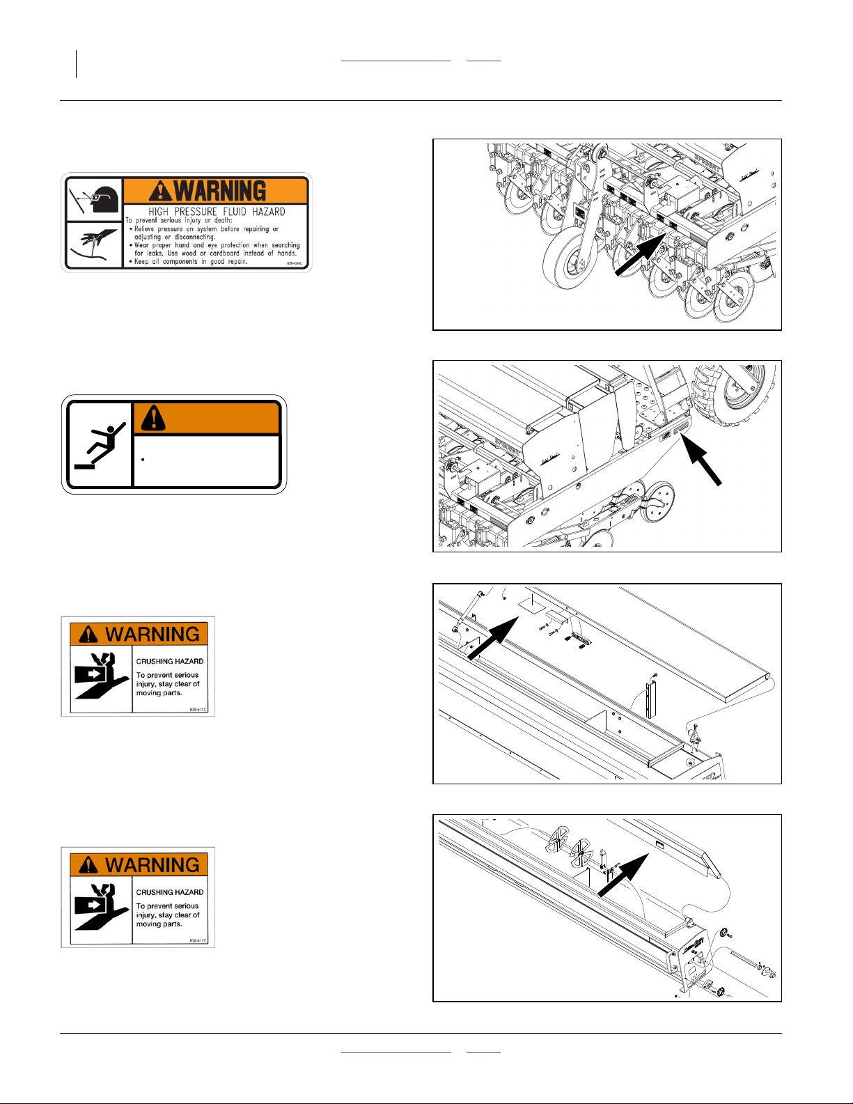
Warning: High Pressure Fluid
838-094C
On front face of upper front cross-tube, left of hitch;
1 total
See “Hitching Tractor to Drill” on page 14.
32546
Warning: Falling Hazard
838-102C
WARNING
To avoid serious injury or death:
Watch your step when climbing ladder or
walking on walkboard.
838-102C
On left side frame at ladder;
1 total
See “Loading Materials” on page 27.
Warning: Hand Crush (Option)
838-611C
Dual Seed: Under lid;
1 total
See “Loading Materials” on page 27.
Warning: Hand Crush (Option)
838-611C
32763
32760
Native Grass: Under lid;
2 total
See “Loading Materials” on page 27.
151-143M Table of Contents Index 2011-12-20
Great Plains Manufacturing, Inc. Table of Contents Index Important Safety Information 9
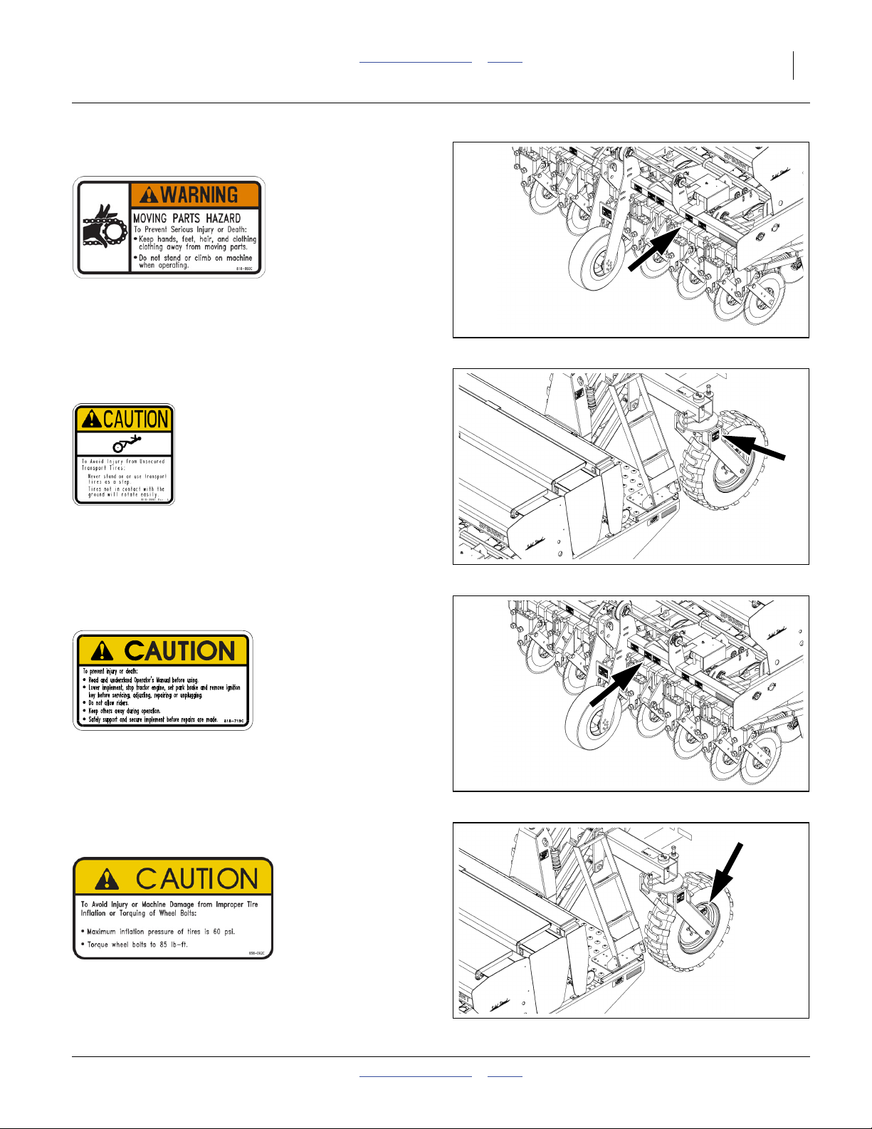
Warning: Moving Parts
818-860C
On front face of upper front cross tube at gearbox;
1 total
32546
Caution: Tires Not A Step
818-398C
On outside face of caster arms above tires;
2 total
See “Tires Not a Step” on page 3.
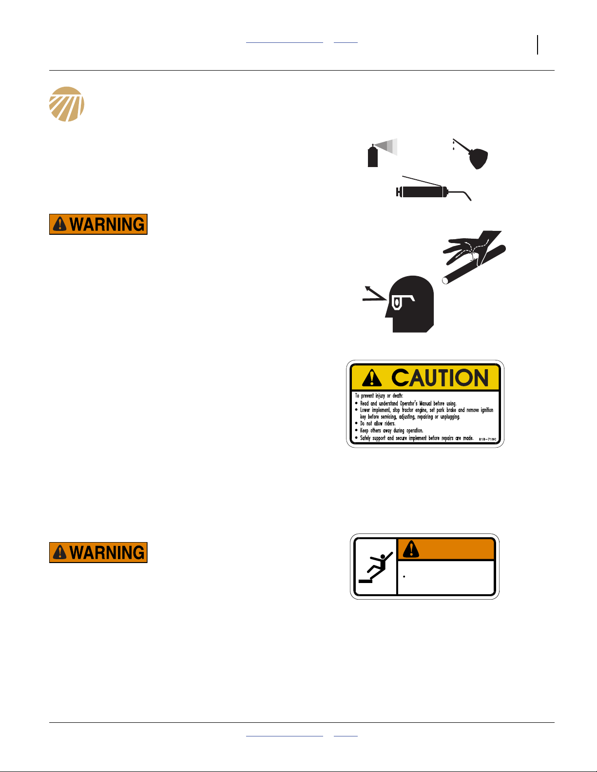
Caution: General
818-719C
On front face of upper front cross tube, left of center;
1 total
See “Important Safety Information” on page 1.
Caution: Tire Pressure and Torque
838-092C
32546
32546
On rim of each lift assist wheel;
2 total
2011-12-20 Table of Contents Index 151-143M
32546
10 3P806NT Table of Contents Index Great Plains Manufacturing, Inc.
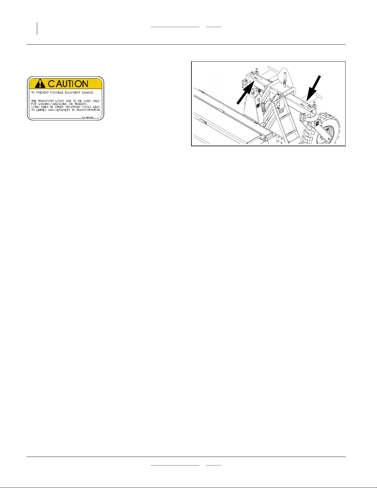
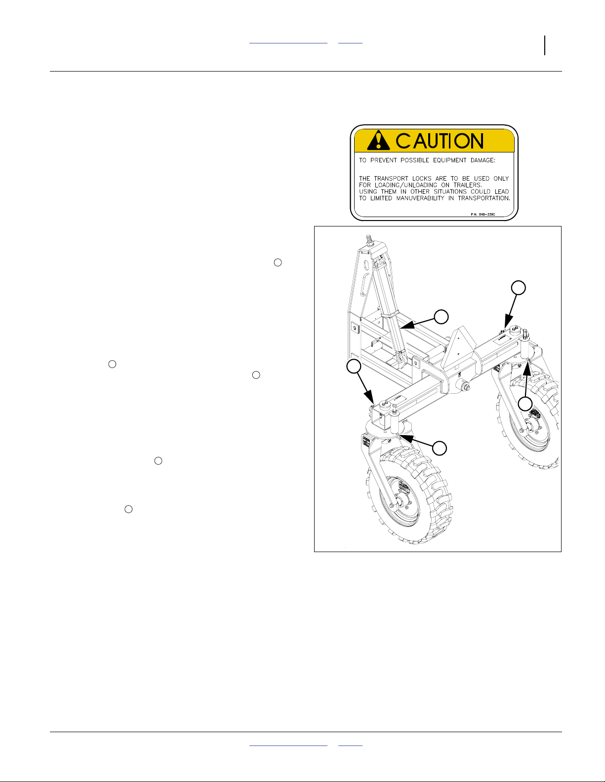
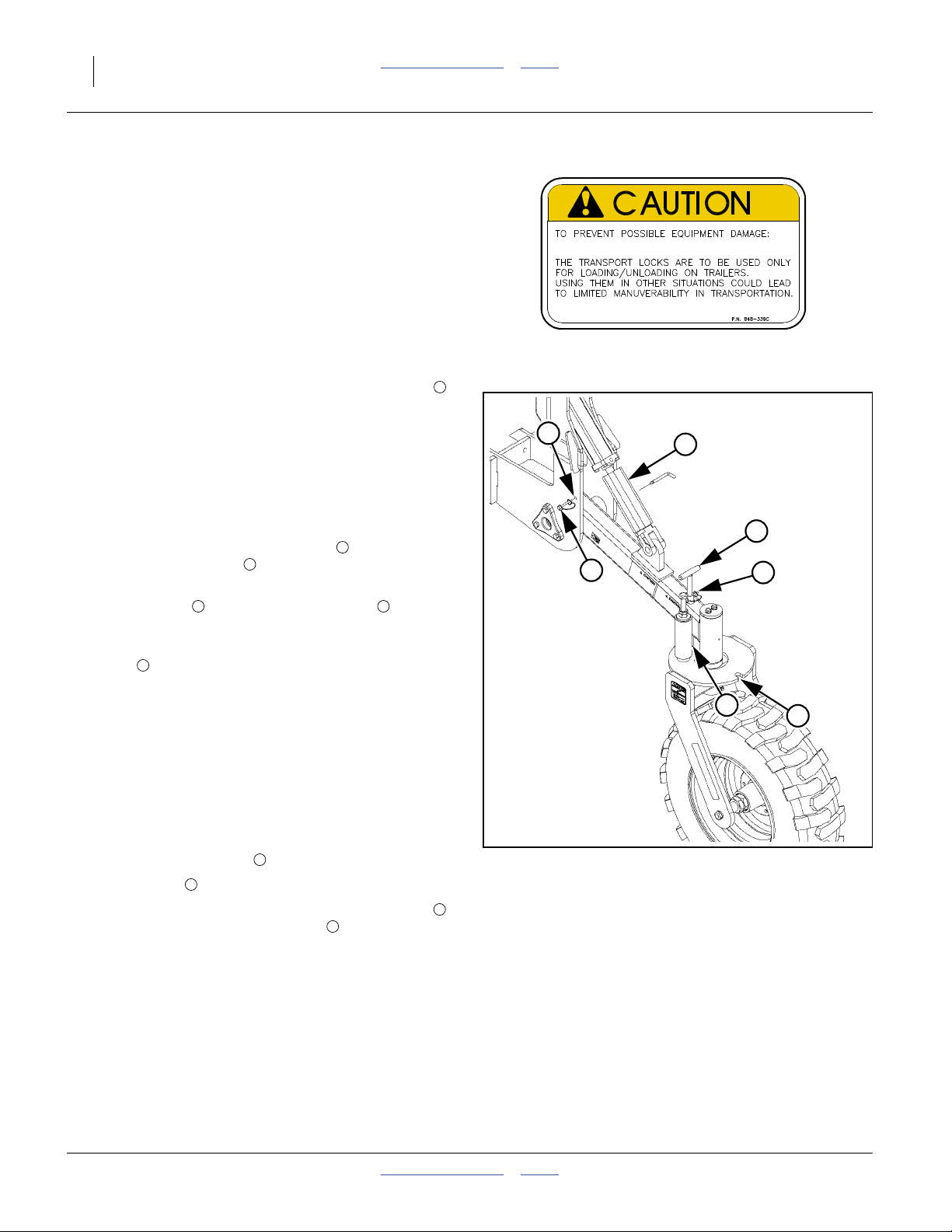
Caution: Transport Locks
848-339C
On top face of caster cross tube;
2 total
32546
151-143M Table of Contents Index 2011-12-20
Great Plains Manufacturing, Inc. Table of Contents Index 11
Introduction
Great Plains welcomes you to its growing family of new
product owners. Your Semi-Mounted 8-Foot No-Till Drill
has been designed with care and built by skilled workers
using quality materials. Proper setup, maintenance, and
safe operating practices will help you get years of
satisfactory use from the machine.
Description of Unit
The 3P806NT is a towed seeding implement. This drill
has a working width of 8 feet (2.5 m). The drill has
straight arm, double disc 06 Series openers. The opener
discs make a seed bed, and seed tubes mounted
between the discs place seed in the furrow. Press
wheels following the opener discs close the furrow and
gauge opener seeding depth. A T-handle on the opener
body makes seeding depth adjustments.
The metering system is driven from the forward gauge
wheel. Seeding rates are set by rate adjustment handles
and a Drive Type gear box for a main seed box. Native
Grass rates are set by sprocket selection.
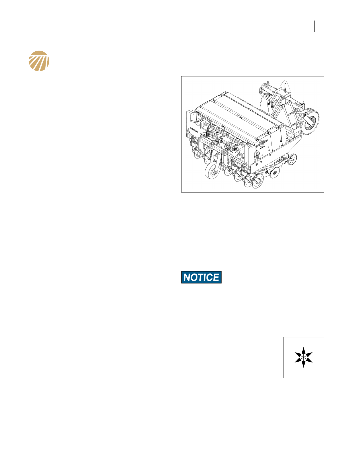
Figure 1: A1057V+
3P806NT Semi-Mounted No-Till Drill
28357
Intended Usage
Use this drill to seed grasses or production-agriculture
crops or to seed over existing grass stands, in ground
conditions that are flat to semi-flat or gently rolling.
Models Covered
This manual applies to Great Plains drill model:
3P806NT-1375 15-row 7.5-inch (19.1 cm)
Standard 3P806NT Models have a main seed box. A
second main seed box (Dual Seed), Fertilizer, Native
Grass and/or Smalls Seeds capability may be added.
This manual covers both current and previous
Great Plains 3P806NT models. Some significant
operating differences are noted by headings with serial
number breaks A1056V- and A1057V+ (“-” is “and
lower”, “+” is “and higher”).
Using This Manual
This manual familiarizes you with safety, assembly,
operation, adjustments, troubleshooting, and
maintenance. Read this manual and follow the
recommendations to help ensure safe and efficient
operation.
The information in this manual is current at printing.
Some parts may change to assure top performance.
Document Family
151-143M Operator Manual (this document)
151-143P 3P806NT Parts Manual
151-143B Seed Rate Manual
Identifies an Economic (not a Safety) Risk:
NOTICE provides a crucial point of information related to the
current topic. Read and follow the instructions to avoid damage
to equipment and ensure desired field results.
Note: This form sets off useful information related to the
current topic, or forestalls possible
misunderstanding.
Right-hand and left-hand as used in
this manual are determined by facing
the direction the machine will travel
while in use unless otherwise stated.
An orientation rose in some line art
illustrations shows the directions of:
Up, Back, Left, Down, Front, Right.
R
F
U
B
L
D
2011-12-20 Table of Contents Index 151-143M
12 3P806NT Table of Contents Index Great Plains Manufacturing, Inc.
Owner Assistance
If you need customer service or repair parts, contact a
Great Plains dealer. They have trained personnel, repair
parts and equipment specially designed for Great Plains
products.
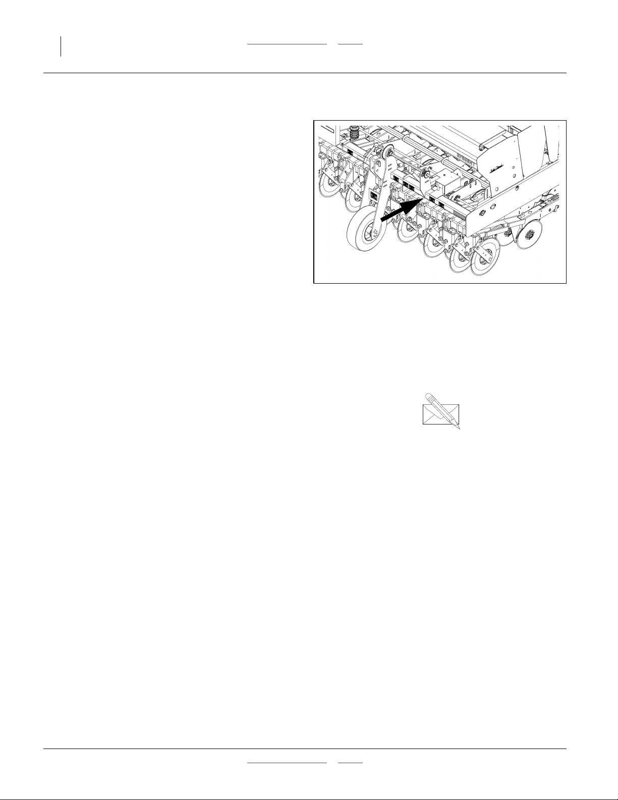
Refer to Figure 2
Your machine’s parts were specially designed and
should only be replaced with Great Plains parts. Always
use the serial and model number when ordering parts
from your Great Plains dealer. The serial-number plate is
located on the top front cross-tube, near the gearbox.
Record your drill model and serial number here for quick
reference:
Model Number:__________________________
Serial Number: __________________________
Figure 2
Serial Number Location
32546
Your Great Plains dealer wants you to be satisfied with
your new machine. If you do not understand any part of
this manual or are not satisfied with the service received,
please take the following actions.
1. Discuss the matter with your dealership service
manager. Make sure they are aware of any problems
so they can assist you.
2. If you are still unsatisfied, seek out the owner or
general manager of the dealership.
For further assistance write to:
Product Support
Great Plains Mfg. Inc., Service Department
PO Box 5060
Salina, KS 67402-5060
gp_web_cs@greatplainsmfg.com
785-823-3276
151-143M Table of Contents Index 2011-12-20

Great Plains Manufacturing, Inc. Table of Contents Index 13
Preparation and Setup
This section helps you prepare your tractor and drill for
use.
Pre-Delivery Setup
If the drill has just been delivered, or has been broken
down for re-shipment, this item needs to be completed
prior to first field use:
• See “Appendix B - Pre-Delivery” on page 78.
You may also need to install features, options and
accessories that are not factory-installed, including:
•“Carbide Disc Scraper Installation” on page 88.
•“Weight Bracket Installation” on page 90
• Native Grass Seed Rate Reduction installation, found
in manual 202-583M in the Reduction kit.
Pre-Planting Setup
The balance of this section covers items that need to be
completed or checked prior to each field use of the drill.
Pre-Setup Checklist
1. Read and understand “Important Safety
Information” on page 1.
2. Check that all working parts are moving freely, bolts
are tight, and cotter pins are spread.
3. Check that all grease fittings are in place and
lubricated. See “Lubrication and Scheduled
Maintenance” on page 54.
4. Re-connect any seed or fertilizer hoses
disconnected for storage. See “Attach Meter Hoses
at Rows” on page 86.
5. Check that all safety decals and reflectors are
correctly located and legible. Replace if damaged.
See “Safety Decals” on page 5.
6. Inflate tires to pressure recommended and tighten
wheel bolts as specified. See “Appendix A -
Reference Information” on page 65.
2011-12-20 Table of Contents Index 151-143M
14 3P806NT Table of Contents Index Great Plains Manufacturing, Inc.
Hitching Tractor to Drill
The 3P806NT is a 3-Point Category II hitch implement,
employed in 2-point Semi-Mounted mode.
Note: The top link of the tractor 3-point is not used for
transport or field operation. Full 3-point mode is
incompatible with lift-assist.
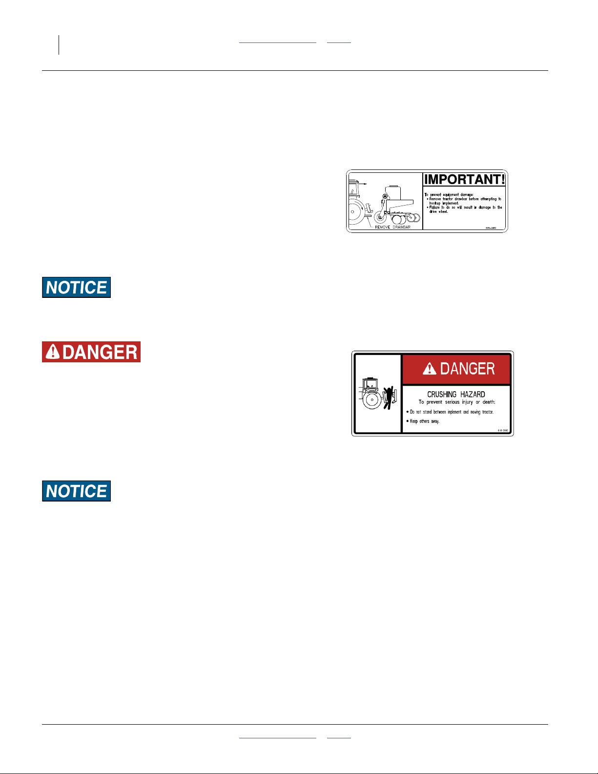
1. Remove tractor drawbar before hitching. The drill
gauge wheel tire or assembly will be damaged if it
contacts the drawbar during hitching, raising or
lowering operations.
2. If a hitch extension is required, install the extension
or setback on the drill, per the instructions at “Hitch
Extension Installation” on page 89, before
continuing with hitching.
Equipment Damage Risk:
Great Plains CPH, PFH or SSH accessory hitches are not
compatible with the 3P806NT.
Crushing Hazard:
You may be severely injured or killed by being crushed
between the tractor and drill. Do not stand or place any part of
your body between drill and moving tractor. Stop tractor
engine and set park brake before installing hitch pins.
3. Raise or lower tractor 3-point lift arms, or hitch
extension, as needed and pin lower arms to drill.
Upper arm is unused.
4. Set your tractor 3-point draft control to Float position.
Equipment Damage Risk:
Do not raise tractor 3-point lift arms until after hydraulic and
electrical connection have been made.
151-143M Table of Contents Index 2011-12-20

Great Plains Manufacturing, Inc. Table of Contents Index Preparation and Setup 15
Hydraulic Hose Hookup
Hydraulic Hose Hookup (s/n A1057V+)
Applies to drills with serial numbers A1057V+
Connect hydraulic system to tractor before lifting the drill.
The hydraulic system of the 3P806NT drill has one
single-acting lift-assist cylinder. (This cylinder has a
larger capacity than the dual cylinders used in the
previous hydraulic system with models A1056V-.) The
cylinder raises the rear of the drill during lift (tractor
3-point lift arms raise the front).
Refer to Figure 3
5. Determine which tractor remote to use for lift assist,
and set the lever for that circuit to Float (to relieve
any pressure).
6. Connect the single lift hose to the Extend port of the
tractor remote.
Note: Prior to first use, adapt the1⁄2in. male NPT hose
1
fitting to a connector compatible with the tractor.
Use liquid pipe thread sealant (not tape) on NPT.
A poppet style QD (Quick Disconnect) to1⁄2in. FNPT
coupler is available as part number 811-856C.
Bleeding Hydraulics
When the hydraulic system is first charged, and if air is
later allowed in the system, it is necessary to bleed it, or
lift may be uneven side to side. See “Bleeding
Hydraulics (s/n A1057V+)” starting on page 52.
High Pressure Fluid Hazard:
Escaping fluid under pressure can have sufficient pressure to
penetrate the skin. Check all hydraulic lines and fittings before
applying pressure. Fluid escaping from a very small hole can
be almost invisible. Use paper or cardboard, not body parts,
and wear heavy gloves to check for suspected leaks. If injured,
seek immediate medical attention from a physician familiar
with this type of injury.
1
Figure 3
Drill Hydraulic System
(s/n A1057V+)
32056
Hydraulic Hose Hookup (s/n A1056V-)
Applies to drills with serial numbers A1056V-
Refer to Figure 4
The hydraulic system of the 3P806NT drill (models with
serial number A1056V-) has two single-acting lift-assist
cylinders. These cylinders raise the rear of the drill
during lift (tractor 3-point lift arms raise the front).
Electrical Connection
Refer to Figure 5
7. Plug the drill lighting connector into tractor outlet.
8. Coil-up and tie-up excess cable, allowing enough
slack for the drill to tilt back if the tractor 3-point lift
arms happen to be raised prior to the lift-assist
circuit.
1
Figure 4
Drill Hydraulic System
(s/n A1056V-)
Figure 5
Lighting Connector
28224
26467
2011-12-20 Table of Contents Index 151-143M
16 3P806NT Table of Contents Index Great Plains Manufacturing, Inc.
Leveling the Drill
Perform leveling in representative field conditions. On
hard ground or pavement, coulters and openers may
prevent determination of drill level.
9. If caster swivel locks were engaged, retract the rods
and pin them up. See “Transporting” on page 25.
10. Extend lever for lift circuit to extend lift-assist
cylinders. See “Drill Lift/Lower (s/n A1057V+)” on
page 20.
11. Remove transport lock channels from lift assist
cylinders. See “Drill Lift/Lower (s/n A1057V+)” on
page 20.
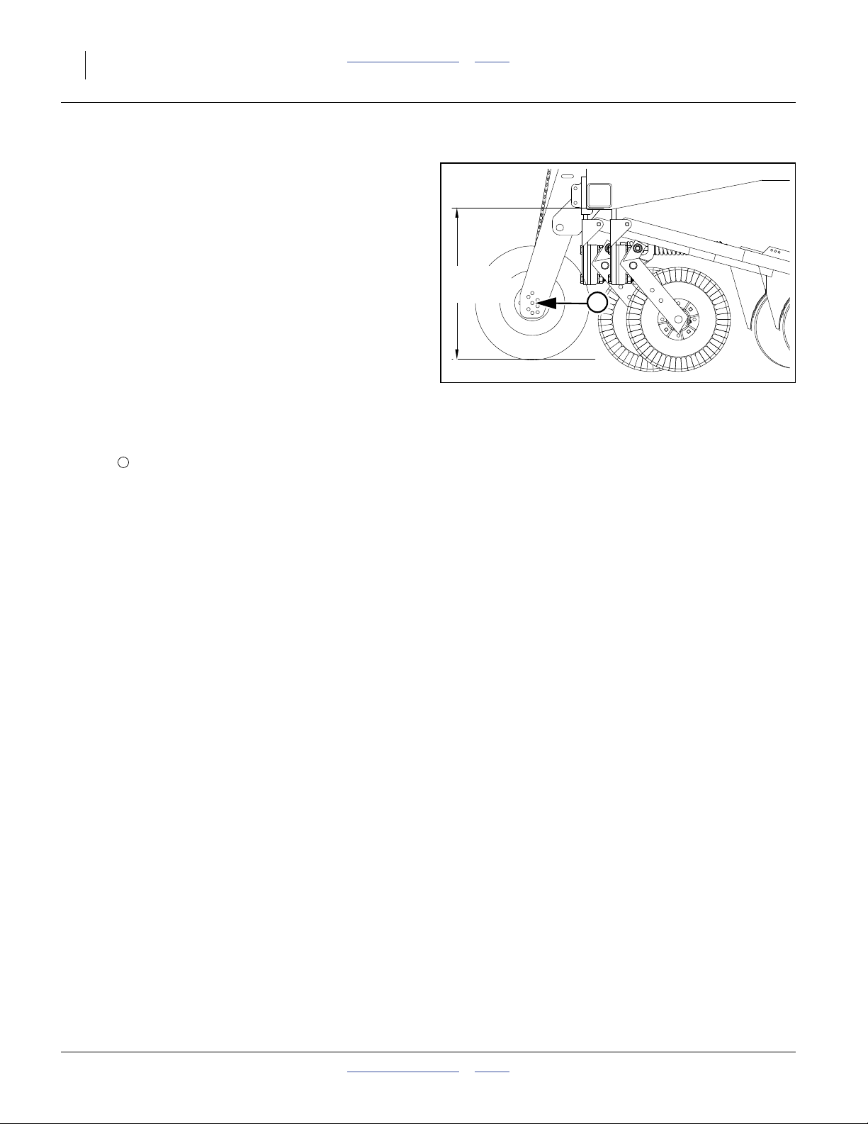
Refer to Figure 6
12. Initially adjust tractor 3-point lift arms so opener tube
runs at the recommended initial height above ground
when drill is lowered in the field.
13. The drive wheel should be in the fourth mounting
1
hole from the top. This is the factory configuration.
Note: The drive wheel axle height may need to be
adjusted due to ground conditions. See page 34.
14. Check level of frame front-to-rear. If not level, adjust
the rear height with the stroke control spacers.
243⁄4 in
62.9 cm
1
Figure 6
Initial Operating Height
18546
151-143M Table of Contents Index 2011-12-20
Great Plains Manufacturing, Inc. Table of Contents Index Preparation and Setup 17
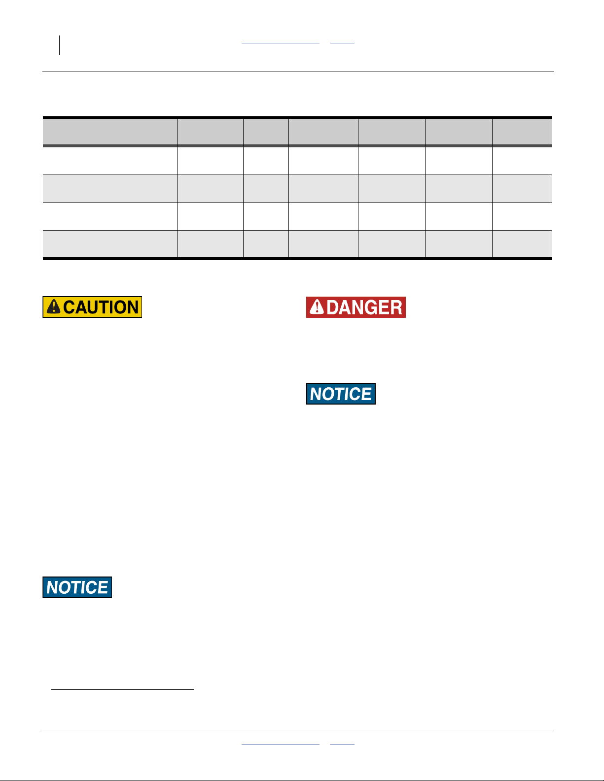
Spacer Sizes
Stack Length 1 in. 1¼ in. 1½ in. 1¾ in.
inches mm 25 mm 32 mm 38 mm 44 mm
Stroke Control Spacers (s/n A1057V+)
(Applies to drills with serial numbers A1057V+
For serial number A1056V-, see page 18.)
The height of the drill at rear (when lowered) is adjusted
with a set of stroke control spacers (part no.
4
810-442C) included with the drill. Five snap-around
spacers are stored on the storage rod for a combined
length of 61⁄2inches (165 mm).
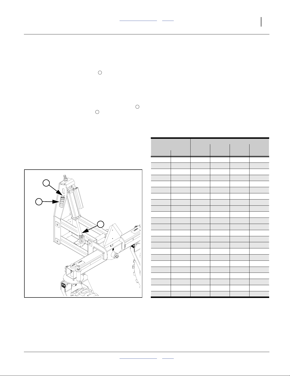
Refer to Figure 7 and the table in Figure 8
15. Remove the desired combination of stroke control
spacers from the lift-assist weldment storage rod
and install on the cylinder rod . There is no factory
6
5
recommendation for this, as it depends on the tractor
used.
Check Level
16. Lower drill until the cylinders rest on the stroke
control spacers. See “Drill Lift/Lower (s/n
A1057V+)” on page 20.
17. Pull drill forward to put coulters and openers in
ground, and assure that lift-assist casters are in
trailing position. Set tractor brakes.
18. When correct level has been achieved, set a stop,
lock or reference indicator on the tractor’s hitch
control to prevent lowering below drill-level.
19. Check level of frame front-to-rear. If not level, adjust
the rear height with the stroke control spacers. If
changed, re-check front tool bar height, and
re-adjust tractor 3-point lift arms. Repeat until level.
Note: If planting in rolling terrain, it may be necessary
to adjust the lift assist cylinders manually with the
tractor hydraulics to allow the machine to float
backwards.
1.00 25 1
1.25 32 1
1.50 38 1
1.75 44 1
5
2.00 51 2
2.25 57 1 1
2.50 64 1 1
4
2.75 70 1 1
2.75 70 1 1
3.00 76 1 1
3.25 83 2 1
6
3.25 83 1 1
3.50 89 2 1
3.75 95 2 1
3.75 95 1 1 1
4.00 102 1 1 1
4.25 108 1 1 1
4.50 114 1 1 1
4.75 121 2 1 1
5.00 127 2 1 1
5.25 133 2 1 1
5.501401111
6.501652111
Figure 7
Stroke Control Spacers (A1057V+)
32057
Figure 8
Stroke Control Spacer Combinations
28359
2011-12-20 Table of Contents Index 151-143M
18 3P806NT Table of Contents Index Great Plains Manufacturing, Inc.
Spacer Sizes
Stack Length 1 in. 1¼ in. 1½ in. 1¾ in.
inches mm 25 mm 32 mm 38 mm 44 mm
Stroke Control Spacers (s/n A1056V-)
(Applies to drills with serial numbers A1056V-
For serial number A1057V+, see page 17.)
The height of the drill at rear (when lowered) is adjusted
with a set of stroke control spacers (part no.
4
810-242C) included with the drill. Five snap-around
spacers stored on each side combine for 20 different
lengths.
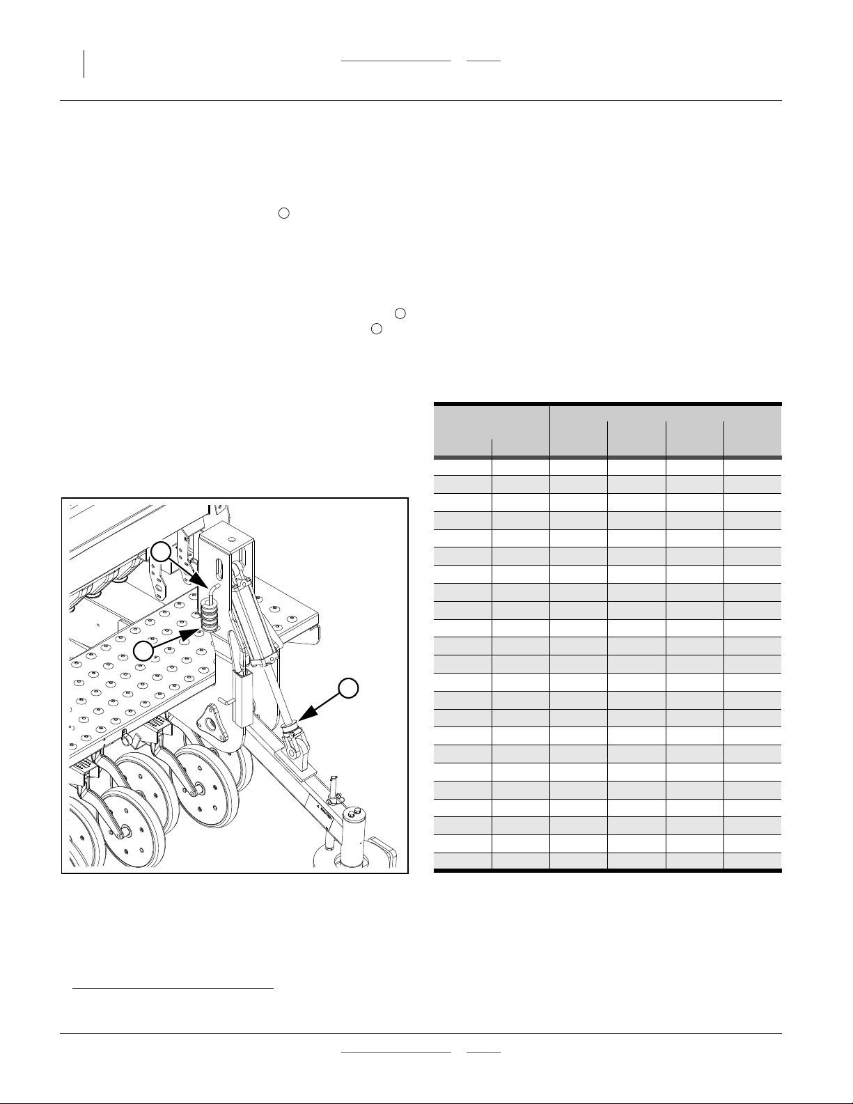
Refer to Figure 7 and the table in Figure 7
1. Remove the desired combination of stroke control
spacers from each lift-assist weldment storage rod
and install the same set
a
on each cylinder rod .
6
There is no factory recommendation for this, as it
depends on the tractor used.
2. Lower drill until the cylinders rest on the stroke
control spacers.
See “Drill Lift/Lower (s/n A1056V-)” on page 21.
3. Pull drill forward to put coulters and openers in
ground, and assure that lift-assist casters are in
trailing position. Set tractor brakes.
4. When correct level has been achieved, set a stop,
lock or reference indicator on the tractor’s hitch
control to prevent lowering below drill-level.
5
5. Check level of frame front-to-rear. If not level, adjust
the rear height with the stroke control spacers. If
changed, re-check front tool bar height, and
re-adjust tractor 3-point lift arms. Repeat until level.
Check Level
Note: If planting in rolling terrain, it may be necessary to
adjust the lift assist cylinders manually with the
tractor hydraulics to allow the machine to float
backwards.
1.00 25 1
1.25 32 1
1.50 38 1
1.75 44 1
2.00 51 2
5
2.25 57 1 1
2.50 64 1 1
2.75 70 1 1
2.75 70 1 1
3.00 76 1 1
4
3.25 83 2 1
3.25 83 1 1
6
3.50 89 2 1
3.75 95 2 1
3.75 95 1 1 1
4.00 102 1 1 1
4.25 108 1 1 1
4.50 114 1 1 1
4.75 121 2 1 1
5.00 127 2 1 1
5.25 133 2 1 1
5.501401111
6.501652111
Figure 9
Stroke Control Spacers (A1056V-)
28361
Figure 10
Stroke Control Spacer Combinations
28359
a. If unequal spacer counts are ever needed to achieve side-to-side level, see “Eyebolt Adjustment” on page 50.
151-143M Table of Contents Index 2011-12-20
Great Plains Manufacturing, Inc. Table of Contents Index 19
Operating Instructions
This section covers general operating procedures.
Experience, machine familiarity and the following
information will lead to efficient operation and good
working habits. Always operate farm machinery with
safety in mind.
Pre-Start Checklist
High Pressure Fluid Hazard:
Escaping fluid under pressure can have sufficient pressure to
penetrate the skin. Check all hydraulic lines and fittings before
applying pressure. Fluid escaping from a very small hole can
be almost invisible. Use paper or cardboard, not body parts,
and wear heavy gloves to check for suspected leaks. If injured,
seek immediate medical attention from a physician familiar
with this type of injury.
1. Carefully review “Important Safety Information”
starting on page 1.
2. Lubricate drill as indicated under “Lubrication and
Scheduled Maintenance” on page 54.
3. Check all tires for proper inflation. See “Tire
Inflation Chart” on page 65.
4. Check all bolts, pins and fasteners. Torque as shown
in “Torque Values Chart” on page 66.
5. Check drill for worn or damaged parts. Repair or
replace parts before going to the field.
6. Check hydraulic hoses, fittings and cylinders for
leaks. Repair or replace before going to the field.
7. Rotate the each ground drive wheel to see that the
drive system and meters are working properly and
free from foreign material.
8. Check that the caster pivots are unlocked.
WARNING
Falling hazard:
Watch your step when walking on drill ladder and walkboard.
Falling from drill could cause severe injury or death.
2011-12-20 Table of Contents Index 151-143M
To avoid serious injury or death:
Watch your step when climbing ladder or
walking on walkboard.
838-102C
20 3P806NT Table of Contents Index Great Plains Manufacturing, Inc.
Drill Lift/Lower (s/n A1057V+)
(applies to drills with serial numbers A1057V+
For serial number A1056V-, see page 21)
Raising and lowering the drill relies on the tractor 3-point
lift arms in front, and hydraulic lift-assist cylinder at rear.
When setup for field use, the hitch and lift circuits may be
operated in any order, or simultaneously. Both, however,
must be lowered for planting, and the lowered hitch
height must be as established at step 14 on page 16.
Raising
1. Raise the tractor 3-point lift arms fully.
2. Activate the lift circuit lever to Extend the lift-assist
cylinder fully. Set circuit to Neutral.
Crushing Hazard:
Rely on circuit Neutral to hold the drill raised only for field
turns. Use parking stands and lock channel for all other raised
operations, transport, parking, maintenance and storage.
Raising after Transport, Parking or Storage
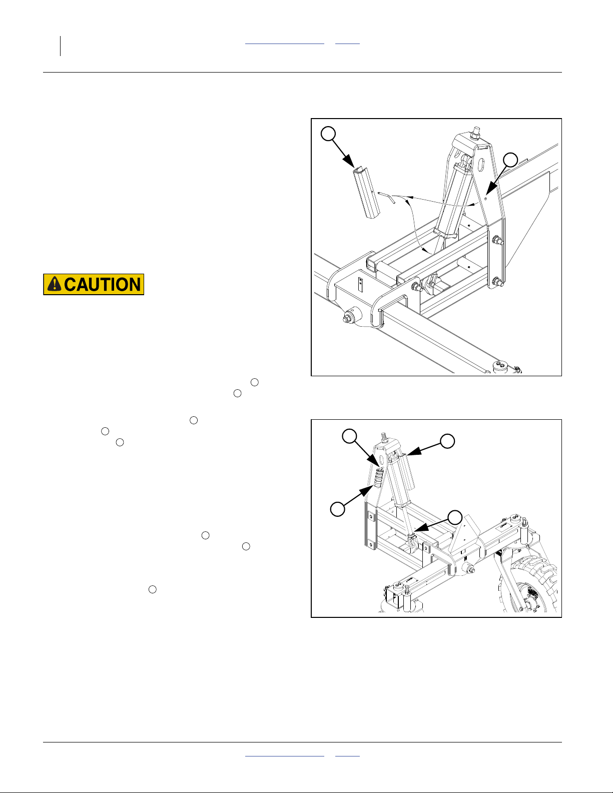
Refer to Figure 11 and Figure 12
3. If raising for planting, remove lock channel from
lift-assist cylinder. Store in the pin hole of the right
1
2
side of lift assist weldment.
4. Install stroke control spacers . Remove needed set
from rod on lift-assist weldment and clamp around
cylinder rod . Use a locally developed spacer
4
5
3
combination (see page 17).
Raising for Transport, Parking or Storage
Refer to Figure 11 and Figure 12
5. If raising for transport or storage, set lift circuit to
neutral to hold at raised. Set tractor parking brake
and shut off tractor.
6. Remove stroke control spacers from lift-assist
cylinder. Store spacers on weldment rod .
5
4
Note: If recently developed or changed, make a note of
the combination removed.
7. Install lock channel on cylinder rod. Secure with
1
pin.
8. Re-start tractor. Slowly move the lift circuit lever to
Retract, allowing the cylinder to settle on the lock
(and relieving pressure from the hydraulic system).
1
2
Figure 11
Lock Channels (s/n A1057V+)
4
1
31920
3
5
Figure 12
Stroke Control Spacers (A1057V+)
32057
151-143M Table of Contents Index 2011-12-20
Great Plains Manufacturing, Inc. Table of Contents Index Operating Instructions 21
Drill Lift/Lower (s/n A1056V-)
(applies to drills with serial numbers A1056V-
for serial number A1057V+, see page 20)
Raising and lowering the drill relies on the tractor 3-point
arms in front, and hydraulic lift-assist cylinders at rear.
When setup for field use, the hitch and lift circuits may be
operated in any order, or simultaneously. Both, however,
must be lowered for planting, and the lowered hitch
height must be as established at step 14 on page 16.
Raising
1. Raise the tractor 3-point lift arms fully.
2. Activate the lift circuit lever to Extend the lift-assist
cylinders fully. Set circuit to Neutral.
Crushing Hazard:
Rely on circuit Neutral to hold the drill raised only for field
turns. Use lock channels for all other raised operations,
transport, parking, maintenance and storage.
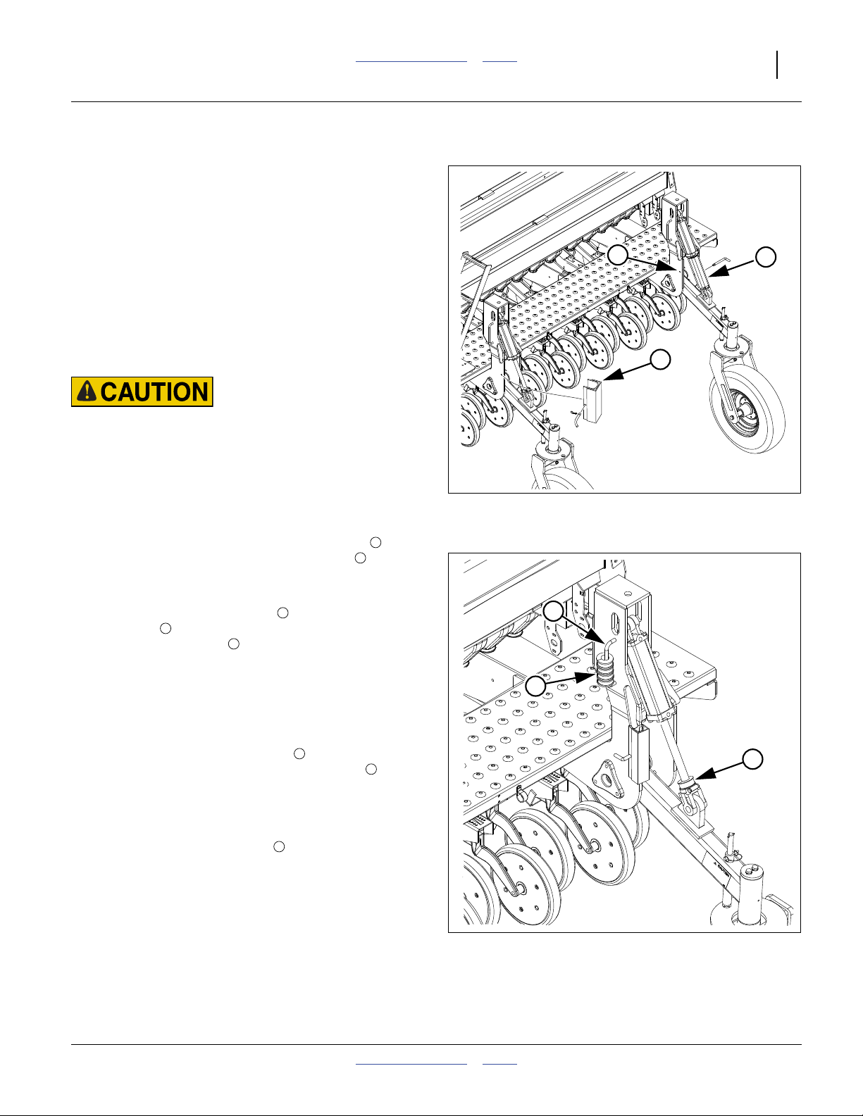
Raising after Transport, Parking or Storage
Refer to Figure 13
3. If raising for planting, remove lock channels from
lift-assist cylinders. Store in the pin holes of the
1
2
inside plates of the lift assist riser weldments.
Refer to Figure 14
4. Install stroke control spacers . Remove needed set
from rods on lift-assist weldments and clamp
around cylinder rods . Use a locally developed
4
5
3
spacer combination (see page 18).
Raising for Transport, Parking or Storage
5. If raising for transport or storage, set tractor parking
brake and shut off tractor.
Refer to Figure 14
6. Remove stroke control spacers from lift-assist
cylinders. Store spacers on weldment rods .
3
4
Note: If recently developed or changed, make a note of
the combination removed.
Refer to Figure 13
7. Remove lock channels from the riser weldments.
1
Install them on the cylinder rods. Secure with pins.
8. Slowly move the lift circuit lever to Retract, allowing
the cylinders to settle on the locks (and relieving
pressure from the hydraulic system).
Lock Channels (s/n A1056V-)
4
3
2
Figure 13
1
1
28353
5
Figure 14
28361
Stroke Control Spacers (A1056V-)
2011-12-20 Table of Contents Index 151-143M

22 3P806NT Table of Contents Index Great Plains Manufacturing, Inc.
Lowering
The lift-assist cylinder(s) is(are) single-acting. Move the
tractor remote circuit lever to Retract. The drill to settles
by gravity. The cylinder piston drives oil back to the
tractor reservoir.
Note: Do not use Float to lower, or the drill will settle
suddenly.
If lowering from transport, parking or storage, it is first
necessary to raise the drill, remove the lock channel(s),
and install the stroke control spacers. See “Leveling the
Drill” on page 16.
1. Slowly move the lift circuit lever to Retract, until each
list-assist cylinder fully settles.
2. Lower the tractor 3-point lift arms to the stop, block
or reference indicator established at step 14 on
page 16.
3. Move lift-assist circuit lever to Float.
4. If about to begin planting, set tractor 3-point hitch to
Float (and not Draft or Depth Control mode).
151-143M Table of Contents Index 2011-12-20
Great Plains Manufacturing, Inc. Table of Contents Index Operating Instructions 23
Caster Pivot Locks (s/n A1057V+)
(applies to drills with serial numbers A1057V+
for serial number A1056V-, see page 24)
To prevent side movement of the drill when transported
by trailer, the lift-assist casters may be locked in their
full-reversing orientation. The lift assist ONLY locks in
reverse.
Use this feature only for trailer transport. Do not use
these locks for semi-mounted towing or field operations.
Locking Casters
Refer to Figure 15
1. With drill hitched, raise both tractor 3-point lift arms
and lift assist (page 20). Install lift lock channel .
2. Pull or back drill onto trailer bed.
Note: On extremely narrow trailer beds, it may be
necessary to lock the casters before moving the
drill onto the trailer. Make sure drill is precisely
aligned for the final move, as maneuverability is
greatly reduced with lock pins in place.
3. On both casters lIft and turn spring loaded lock pin
plungers 90 degrees. Move in reverse, lock pins
snap into place in the caster plate cutouts when
aligned under each lock tube.
4. Lower drill.
Unlocking Casters
Refer to Figure 15
1. Hitch drill before unlocking.
2. Leave the lock pins in place until the drill is
removed from the trailer, unless the trailer bed has
more than ample width to permit casters to safely
make a full turn.
3. Lift lock pins out of lock plate holes and turn 90
degrees to hold in the unlock position.
2
2
2
1
2
1
3
2
3
3
Figure 15
Caster Pivot Locked (s/n A1057V+)
2011-12-20 Table of Contents Index 151-143M
32058
24 3P806NT Table of Contents Index Great Plains Manufacturing, Inc.
Caster Pivot Locks (s/n A1056V-)
(applies to drills with serial numbers A1056V-
for serial number A1057V+, see page 23)
To prevent side movement of the drill when transported
by trailer, the lift-assist casters may be locked in their
full-trailing or full-reversing orientations.
Use this feature only for trailer transport. Do not use
these locks for semi-mounted towing or field operations.
Locking Casters
Refer to Figure 16
1. With drill hitched, raise both tractor 3-point lift arms
and rear ends (page 21). Install lift lock channels .
2. Pull or back drill onto trailer bed.
Note: On extremely narrow trailer beds, it may be
necessary to lock the casters before moving the
drill onto the trailer. Make sure drill is precisely
aligned for the final move, as maneuverability is
greatly reduced with lock pins in place.
3. Pull forward, or reverse, until casters are in desired
orientation, and a lock plate cutout is aligned
under each lock tube .
4. At both left and right lift assist arms, remove the
retaining pins , allowing the locking pin to fall
into the lock plate cutout.
5. Store the retaining pins in the lock channel storage
6
holes of the lift assist riser weldment.
6. Lower drill.
Unlocking Casters
Refer to Figure 16
1. Hitch drill before unlocking.
2. Leave the lock pins in place until the drill is removed
from the trailer, unless the trailer bed has more than
ample width to permit casters to safely make a full
turn.
3. Retrieve retaining pins from storage locations.
4. Lift lock pins out of lock plate holes.
5. Align hole in lock pin with hole in upper lock tube .
Secure lock pin with retaining pin .
4 5
5
3
4
2
4
1
6
1
5
4
Figure 16
Caster Pivot Locked (s/n A1056V-)
3
4
3
2
31633
151-143M Table of Contents Index 2011-12-20
Great Plains Manufacturing, Inc. Table of Contents Index Operating Instructions 25
Transporting
Instructions and advisories for transport depend on the
method of transport. Towing behind a tractor is covered
on this page under “Semi-Mounted 3-Point Transport”.
Transport via trailer is covered under “Trailer Transport”
on page 26.
Semi-Mounted 3-Point Transport
Excessive Speed Hazard:
Loss of Control Hazard:
Tow the drill on its own tires only with a 3-point tractor.
Towing with any other hitch type is likely to result in loss of
control and a serious accident, with risk of injury or death,
and almost certain major equipment damage.
Before transporting with a tractor, check these items:
1. Check that tractor is sufficient for towing the drill.
Tractor must have at least 80 horsepower (60 kW).
Use a tractor with adequate lift capacity, and that is
weighted to maintain steering control. See the table
on next page for weights of typical drill
configurations. Tractor must have sufficient front-end
weights.
2. Unload drill boxes. The drill can be transported with
full boxes of material (other than native Grass), but
the added weight increases stopping distance and
decreases maneuverability. Unload before
transporting if possible.
3. Raise drill completely (page 20).
4. Install lock channels on lift cylinders (page 20).
Note: The cylinder lock can be secured or removed only
after the drill is fully raised.
5. Check that caster locks are disengaged (page 23).
Keep Clearance in Mind
Remember that the drill may be wider than the tractor.
Allow safe clearance.
Observe Road Rules
Comply with all national, regional and local safety laws
when traveling on public roads.
Towing the drill at high speeds or with a vehicle that is too
light can lead to loss of vehicle control and a serious road
accident, injury and death. To reduce the hazard, do not
exceed 20 mph. Check that your tractor has enough ballast to
handle the weight of the drill. Refer to your tractor operator’s
manual for ballast requirements.
Road Accident Hazard:
Failure of hydraulic cylinders or tractor circuit during
transport will cause drill to drop suddenly, which could lead to
serious road accidents, injury or death. To prevent an
accident, always install cylinder locks before transporting
drill.
Equipment Damage Risk:
Do not tow on drill wheels with caster locks installed. They are
unnecessary in semi-mounted towing and dramatically reduce
turning ability. Tractor towing with caster locks is likely to
result in equipment damage. If locks are installed, remove
them (page 23).
Operator Confusion Risk:
Semi-mounted implements with rear lift-assist wheels
maneuver differently in field and highway transport, compared
to pull-type implements. Observe caution when turning and
transporting.
Seeding Risk:
Do not transport with seed loaded in Native Grass box.
Heavier mix components settle to the bottom, which can
prevent drive system from operating, and results in irregular
seed rate and population distribution.
2011-12-20 Table of Contents Index 151-143M
26 3P806NT Table of Contents Index Great Plains Manufacturing, Inc.
Typicala 3P806NT Weights by Configuration
Standard Drill
Option (40)
Drill with
Fertilizer
Drill with NG
(Native Grass)
Drill with SGS
(Small Seeds)
Drill with
Fert. and SGS
Drill with
NG and SGS
All Boxes Empty 4054 lbs 4269 lbs 4386 lbs 4166 lbs 4340 lbs 4500 lbs
1839 kg 1936 kg 1990 kg 1890 kg 1969 kg 2041 kg
Full Main Box and 5078 lbs 5851 lbs 5410 lbs 5190 lbs 5922 lbs 5524 lbs
Full Fertilizer (if present)
2303 kg 2654 kg 2454 kg 2354 kg 2686 kg 2506 kg
All Boxes Empty 5213 lbs 5429 lbs 5546 lbs 5326 lbs 5500 lbs 5659 lbs
with Weights
2365 kg 2462 kg 2516 kg 2416 kg 2495 kg 2567 kg
Full Main Box, Weights, 6237 lbs 7011 lbs 6570 lbs 6350 lbs 7082 lbs 6683 lbs
Full Fertilizer (if present)
2829 kg 3180 kg 2980 kg 2880 kg 3212 kg 3032 kg
32337A
Trailer Transport
Load Maneuvering Hazard - Use care and planning when
loading or unloading the drill in trailer transport. The rear
casters may turn and force the drill off the trailer.
▲ Make sure the trailer is rated for the load.
▲ Make the trailer is wide enough for the load.
▲ Make sure the load is secured properly.
Loading Trailer
1. Hitch suitable 3-point tractor with available hydraulic
remote (page 15).
2. Raise drill (page 20).
Unstable Load Hazard - Do not transport on a trailer of
insufficient width or length. Unless both caster tires are on the
bed, too few openers are supporting the entire drill. The load
may spill, with risk of serious injury or death to anyone
nearby, and certainty of major equipment damage.
Equipment Damage Risk - The drill must be hitched to a
3-point tractor for any movement. Coulter or opener damage
is likely if unhitched movement is attempted. Observe all
hitching precautions.
Loading with Casters Locked
3. Carefully line-up the tractor, drill and trailer, so that:
a. no turns are needed for the final movement, and
b. the casters are fully reversed.
4. Install caster swivel lock pins (page 23).
5. Carefully back the drill onto the trailer bed.
6. Lower the drill (page 22).
7. Secure the load with cargo straps or chains.
Unloading Trailer
1. Check that casters are still locked.
2. Release cargo straps or chains.
3. Hitch suitable 3-point tractor with available hydraulic
remote (page 15).
4. On a narrow trailer, confirm that caster pivot swivel
locks are still in place (page 23).
5. Raise drill (page 20).
6. Carefully tow drill from trailer.
7. Remove caster pivot swivel locks (if engaged,
Great Plains recommends locking casters prior to loading for
trailer transport, and leaving them locked for transport and
unloading. This reduces the risk of loading and transport
accidents which could result in significant implement damage.
a. Weights are for serial number A1057V+, are approximate, and can vary by hundreds of pounds based on material density, press wheel
options, accessories and user modifications. Weight kit figures presume 10 each 100 pound suitcase weights.
151-143M Table of Contents Index 2011-12-20
page 23).
8. Unless arriving at planting ground, install lift-assist
cylinder transport locks (page 20).
 Loading...