

Page 1
Great Plains Mfg., Inc.
s
Installation Instructions 1
Small Seeds Option
5- and 6-Foot Drills
Used with:
• 3P500, 3P600
• 605NT, 606NT
• 3P605NT, 3P606NT
General Information
These instructions explain how to install a Small Grass
Seeds (SGS) assembly on a compatible drill.
The Small Seeds option adds the capability to meter the
smallest of seeds at rates more precise than using the
main seed box for those seeds.
These instructions apply to an installation of:
Kit Kit Description
133-124A 605NT 7 1/2" SGS ASSEMBLY
133-131A 3P605NT 7 1/2" SGS ASSEMBLY
133-133A 6’ 6" SGS
133-134A 6’ 7 1/2" SGS
133-150A 5’ 6" SGS
133-151A 5’ 7 1/2" SGS
133-369A 3P605NT FIELD SGS ON NG
133-370A 605NT FIELD SGS ON NG
When you see this symbol, the subsequent instruction
and warnings are serious - follow without exception.
!
Your life and the lives of others depend on it!
One kit updates one drill.
Drill Model Uses Kit
3P500-0775 (7.5 in) 133-151A
3P500-0906 (6 in) 133-150A
3P500V (any spacing) (SGS not available)
3P600-0975 (7.5 in) 133-134A
3P600-1106 (6 in) 133-133A
3P605NT-0975 (7.5 in) 133-131A or 133-369A
3P606NT-0975 (7.5 in) 133-131A or 133-369A
605NT-0975 (7.5 in) 133-124A or 133-370A
606NT-0975 (7.5 in) 133-124A or 133-370A
Related Documents
Have the Operator Manual at hand for drill movements.
118-794M 3P500-3P600 OPERATORS MANUAL
151-061M MANUAL 605NT OPERATOR
Have the current Parts Manual at hand for parts ID.
118-794P 3P500-3P600 PARTS MANUAL
151-061P MANUAL 605NT PARTS
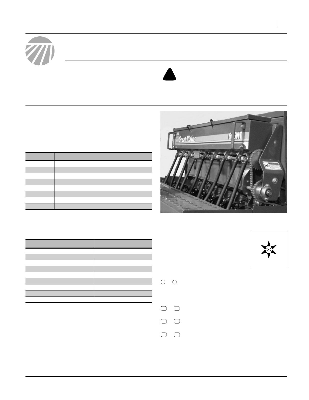
Figure 1
Small Seeds Box and Hoses
Notations and Conventions
“Left” and “Right” are facing in the
direction of machine travel. An orientation rose in the line art illustrations
shows the directions of Left, Right,
Front, Back, Up, Down.
Call-Outs
1 9
to
11 45
to
and
61 67
to
81 96
to
Single-digit callouts identify components in
the currently referenced Figure or Figures.
These numbers may be reused for different
items from page to page.
Two-digit callouts in the ranges:
11 to 45 reference kit parts, and
61 to 67 reference optional parts from the
new parts lists beginning on page 18.
Two-digit callouts in the range 81 to 96 reference affected existing parts from the table on
page 20. The descriptions match those in
your Parts Manual. The narrative and table
indicate any re-use of the parts.
18484
U
F
L
R
B
D
©Copyright 2000, 2006, 2009 Printed 04/02/2009 133-140M
Page 2

2 Small Seeds Option
Before You Start
Compatibility
Refer to Figure 2
1. Make sure that the drill is a compatible model for the
kit. See table on page 1. The full model number for
the drill is found on the serial number plate.
2. If the drill is a model 605NT or 606NT, you may want
to replace the ‘606 decal in the kit with the correct
decal for your drill. It is not necessary to have these
decals on hand during the kit installation.
Order one of:
67
838-207C DECAL 605NT
838-203C DECAL 3P605NT
Inventory
3. Make sure all parts are present. Remove all parts
and any packing material from inside the new Small
Seeds box.
Great Plains Mfg., Inc.
Comprehension
4. Review these instructions. Make sure the installers
understand where each part or assembly is
installed, and what tools are required for the task.
Note: Illustrations in this manual, based on the parts
manuals for this family of drills, may show
exploded views that are fully disassembled. Rely
on the instructions for required disassembly and reassembly steps.
Pre-Assembly Preparation
Tools Required
• updated drill Parts Manual (see page 1)
• suitable tractor for positioning and lowering drill
• blocks for securing transport tires if drill will be
unhitched for the work
• two people or a hoist - several longs parts are suitable
for unassisted single-person removal/installation
• chain lube
• basic hand tools, including:
snap ring pliers
Figure 2
Serial Number Plate
18515
133-140M 04/02/2009
Page 3
Great Plains Mfg., Inc.
Work Location
5. Move the drill to a location with:
• room to maneuver large parts around it,
• access to tractor or hydraulic power,
• adequate illumination, and;
• clear surface beneath for recovery of any falling
or dropped parts - if the surface is not clear, have
a tarp or drop cloth available.
6. Park the drill per the instructions in the Operator
Manual.
7. Lower the drill and the openers
8. Shut off tractor if left hitched.
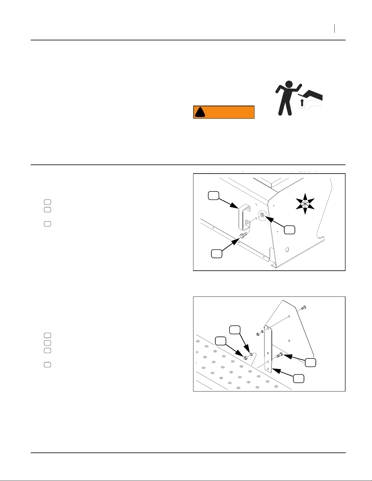
Remove Existing Parts
Refer to Figure 3
9. At each grab handle on the back corners of the rearmost seed box, remove and save two sets (four sets
total) of:
88
802-203C HFSS 1/2-13X1 1/2 GR5
92
803-169C NUT HEX FLG. LOCK 1/2-13 PLT.
and two:
81
119-190D HANDLE
These are re-mounted on the new SGS box at
step 15 on page 4.
Note: Existing hardware may vary slightly from parts
called out in these instructions. For example,
instead of flange nuts, there may be separate
washers and there may be a 133-045D strap. Note
such changes, so that parts are correctly reinstalled.
Refer to Figure 4
Step 10 is required only for drills with existing Native
Grass boxes, but is recommended for all drills, to clear
access for mounting the SGS box.
10. At the SMV placard remove and save two sets:
85
802-007C HHCS 5/16-18X3/4 GR5
93
804-009C WASHER LOCK SPRING 5/16 PLT
89
803-008C NUT HEX 5/16-18 PLT
and then remove the still-assembled SMV
96
890-153C SMV MOUNTING BLADE
Installation Instructions 3
WARNING
!
Negative tongue weight hazard:
Lower the openers on pull-type drills. The weight of a person
on raised openers can cause an unhitched tongue to fly up,
causing a fall and possible serious injury.
U
81
L
B
F
R
D
92
88
Figure 3
Dismount Grab Handle
18651
93
89
85
96
Figure 4
Dismount SMV
04/02/2009 133-140M
18565
Page 4
4 Small Seeds Option
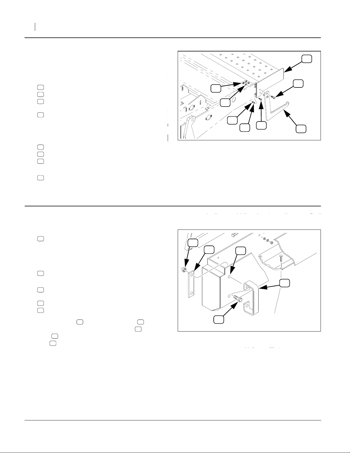
Refer to Figure 5
Step 11 through step 13 are performed only if the drill
has a Native Grass seed box installed. For Main-box-only
drills, skip to step 16 on page 5.
11. At each end of the walkboard, remove and save two
sets (four sets total):
87
802-091C HHCS 1/2-13X1 1/2 GR5
95
804-015C WASHER LOCK SPRING 1/2 PLT
91
803-020C NUT HEX 1/2-13 PLT
then remove and save two steps:
82
119-192D STEP
Note: Two people or a hoist are required for this step.
12. At each end of the walkboard, remove and save four
sets (eight sets total):
86
802-079C HHCS 3/8-16X1 1/4 GR5
89
804-013C WASHER LOCK SPRING 3/8 PLT
90
803-014C NUT HEX 3/8-16 PLT
13. Remove the walkboard:
83
119-272H SEED & SGS WALKBOARD WELDMENT
The walkboard is not re-used.
Great Plains Mfg., Inc.
91
95
90
86
89
Figure 5
Dismount Walkboard (NG only)
83
87
82
18565
Attach SGS box & Final Drive
Re-Install Grab Handles
Refer to Figure 6
14. Select the SGS box from your kit, one of:
16
133-129L 6’ 7 1/2" SGS BOX ASSY
133-135L 6’ 6" SGS BOX ASSEMBLY
133-148L 5’ 6" SGS BOX ASSEMBLY
133-149L 5’ 7 1/2" SGS BOX ASSEMBLY
and two new:
15
133-045D SGS BOX SUPPORT STRAP
15. Select two saved:
81
119-190D HANDLE
and four sets saved hardware, typically:
88
802-203C HFSS 1/2-13X1 1/2 GR5
92
803-169C NUT HEX FLG. LOCK 1/2-13 PLT.
Insert the bolts through the handles , then
through the rear holes of the SGS box . Add a
15
strap to each handle assembly, and secure with
92
nuts (and any washers removed at step 9).
88 81
16
92
15
16
88
Figure 6
Re-install grab Handles
81
18568
133-140M 04/02/2009
Page 5
Great Plains Mfg., Inc.
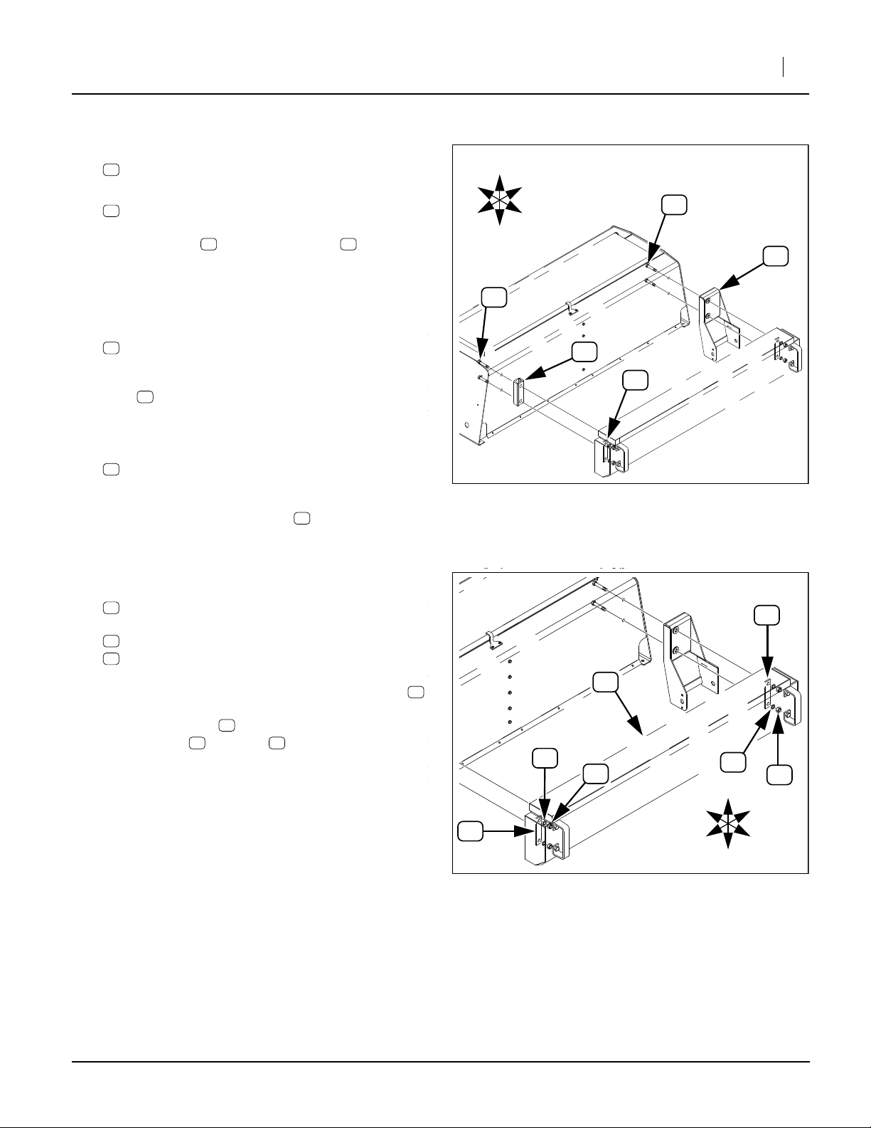
Attach SGS Box
Refer to Figure 7
16. If removed at step 9, select two saved:
84
133-045D SGS BOX SUPPORT STRAP
17. Select four new:
28
802-041C HHCS 1/2-13X3 1/2 GR5
Insert the bolts through the straps (if present
- newer drills have internal stiffener plates and do
not require straps). From the inside of the box,
insert the bolts, or bolt/strap assemblies, through
the holes previously used for the grab handles.
18. Select one new:
24
202-186D NG/SGS BOX SPACER
28 84
Installation Instructions 5
U
F
R
28
L
B
D
17
28
24
Place this spacer over the threaded ends of the
28
bolts at the left end of the existing seed box. If it
tends to fall off, use saved 1/2-13 nuts to temporarily
hold it.
19. Select one new:
17
133-130K 6’ SGS DRIVER ASSY
With the sprocket drive end down, place this over
the threaded ends of the bolts at the right end of
the existing seed box. If it tends to fall off, use saved
1/2-13 nuts to temporarily hold it.
Refer to Figure 8
20. Select two new
15
133-045D SGS BOX SUPPORT STRAP
and four sets new:
35
804-015C WASHER LOCK SPRING 1/2 PLT
31
803-020C NUT HEX 1/2-13 PLT
Remove any temporary nuts. Place the SGS box
over the bolts inserted at step 17. Inside the SGS
box, place a strap over the same bolts. Secure
with washers and nuts .
15
35 31
28
16
15
84
Figure 7
Prepare for SGS Box Install
16
35
31
Figure 8
Install SGS Box
18566
15
35
31
U
F
L
R
B
D
18566
04/02/2009 133-140M
Page 6
6 Small Seeds Option
Install SGS Drive
Install 3P500/3P600 Drive Components
Install 3P500/3P600 Shaft Bearings
For 3P605NT, 3P606NT, 605NT or 606NT, skip to
“Install 3P/605/606NT Drive Components” on page 10.
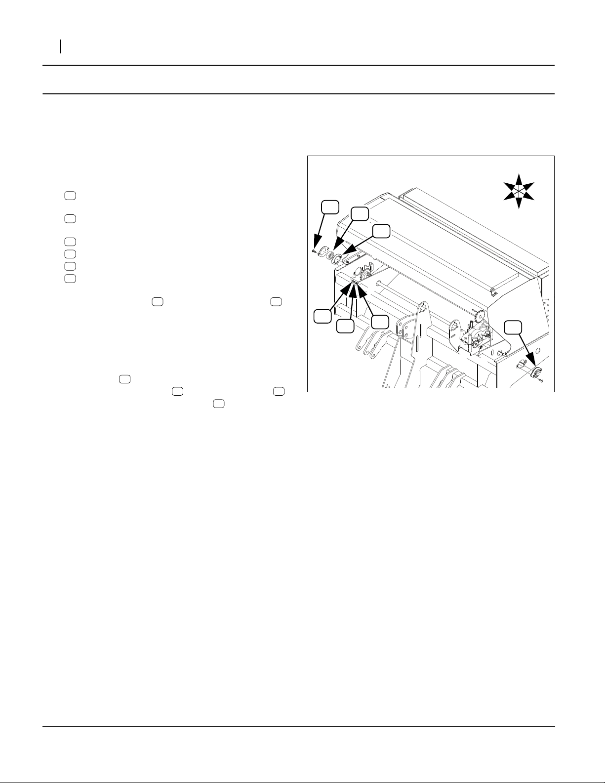
Refer to Figure 9
21. Select two (2) new:
43
822-040C BRG INS .75IDX1.85OD SPH LCK
four new:
44
822-041C FLANGETTE 47 MST
and four sets new:
29
802-282C RHSNB 5/16-18X1 GR5
37
804-036C WASHER FLAT 5/16 SAE PLT
34
804-009C WASHER LOCK SPRING 5/16 PLT
30
803-008C NUT HEX 5/16-18 PLT
29
43
44
Great Plains Mfg., Inc.
U
R
F
B
L
D
Place each bearing between two flangettes .
As necessary, back out set screws in lock collars so
that bearings can slide freely on shaft. Bearing lock
collars (not shown) are oriented to drill center
(inside). Mount each flangette on the forward bearing opening on the outside of the end panels.
Insert a bolt through the flangettes and the
panel. Add a flat washer , then a lock washer ,
and secure to finger-tight with nut .
29
43 44
37 34
30
37
34
30
Figure 9
Install 3P500/600 Bearings
44
18655
133-140M 04/02/2009
Page 7
Great Plains Mfg., Inc.
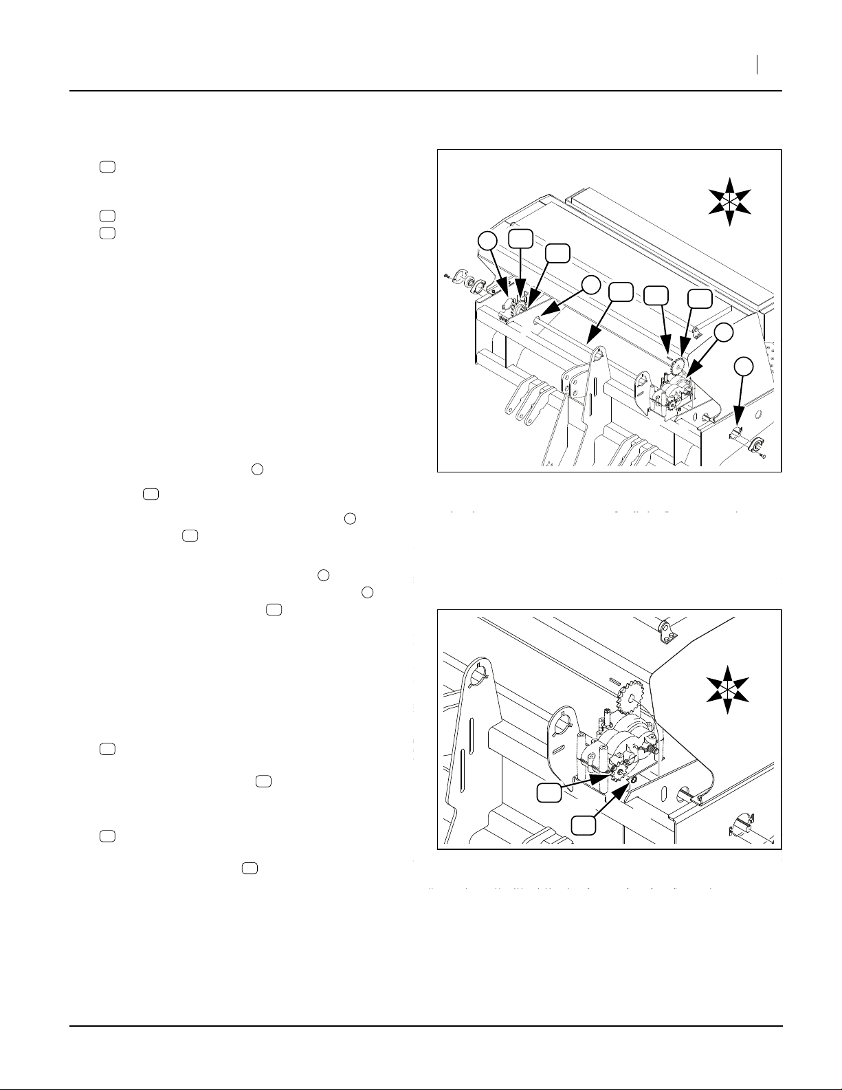
Install 3P500/3P600 Shaft and Sprockets
Refer to Figure 10
22. Select the shaft in your kit, one of:
14
133-037D SGS/AUXILLARY DRIVE SHAFT
133-052D 5’ SGS DRIVE SHAFT
and one each new:
40
808-170C SPKT 40B17 X 3/4BORE W/KW&SS
38
808-100C SPKT 40B22 3/4B W/K.W. &SS
As necessary, back out the set screws in the
sprockets so that the sprockets can slide freely on
the shaft.
Note: The shaft has keyways of different lengths on each
end. The end with the shorter keyway is the right
end. The end with the longer keyway is the left
(gearbox) end. The shaft may be inserted in the
drill from either side, as long as the sprockets are
correctly oriented. These steps use the left side.
Note: The sprockets are not symmetrical. For ease of
future maintenance, the set-screw side is oriented
to drill center.
23. Insert the right (short keyway) end of the shaft
through the new bearing .
Note: Keys are installed at step 31 and step 35.
24. As the shaft passes behind the gearbox , add the
22T sprocket , with the set screw side facing
right.
23
38
1
2
Installation Instructions 7
U
R
F
40
4
B
L
D
23
3
14
23
38
2
1
Figure 10
Install 3P500/600 Shaft
18655
25. As the shaft nears the right bearing (and after
passing through the right-most brace-plate , if
any), add the 17T sprocket , with the set screw
side facing left.
26. Adjust lateral shaft position so that about equal
lengths of shaft end are exposed at the end panels.
Rotate shaft to ensure it spins freely. Secure both
bearing lock collars.
Refer to Figure 11
27. Select one each new:
39
808-160C SPKT 40B12 X 36T SPLINE BORE
Place the spline sprocket , raised hub side first,
onto the left front gearbox shaft.
28. Select one each new:
25
800-141C SNAP RING EXT F/PEERLESS G.B.
Secure spline sprocket to gearbox shaft with
snap ring.
40
39
39
4
3
39
25
Figure 11
3P500/600 Gearbox Sprocket
R
F
U
B
L
D
18655
04/02/2009 133-140M
Page 8

8 Small Seeds Option
Install 3P500/3P600 Drive Idlers
3P500/3P600 Right Idler
Refer to Figure 12
29. Select one set new:
28
802-041C HHCS 1/2-13X3 1/2 GR5
42
817-025C NO. 40 12T IDLER SPKT.
32
803-036C NUT HEX JAM 1/2-13 PLT
36
804-017C WASHER FLAT 1/2 USS PLT
33
803-169C NUT HEX FLG. LOCK 1/2-13 PLT.
Place the idler on the bolt . Thread the jam
32
nut all the way on, then back off one turn. Add
the flat washer .
30. Using the flange lock nut , loosely secure the
idler assembly to the idler weldment at drill right
(near the new 17T sprocket ).
31. Select one new:
23
168-127D 3/16 X 1 KEY (not shown)
42 28
36
33
5
40
33
40
Great Plains Mfg., Inc.
U
R
B
5
36
32
F
L
D
42
28
28
42
32
36
Adjust the position of the 17T sprocket until the
teeth are in the same rotational plane as those of
the new idler . Insert the key in the 17T
sprocket. Secure the set screw in that sprocket.
42 23
40
3P500/3P600 Left (Gearbox) Idler
32. Locate the idler slot to use. Align the new 22T
sprocket with the new spline sprocket on the
gearbox. Locate the nearest
ward of the 22T sprocket and on an adjacent brace
plate.
33. Select one set new:
28
42
32
36
33
Place the idler on the bolt . Thread the jam
nut all the way on, then back off one turn. Add
the flat washer ,
34. Using the flange lock nut , loosely secure the
idler assembly at the slot identified in step 32.
35. Select one new:
23
38 39
1
⁄
in slot that is for-
2
802-041C HHCS 1/2-13X3 1/2 GR5
817-025C NO. 40 12T IDLER SPKT.
803-036C NUT HEX JAM 1/2-13 PLT
804-017C WASHER FLAT 1/2 USS PLT
803-169C NUT HEX FLG. LOCK 1/2-13 PLT.
42 28
32
36
33
6
168-127D 3/16 X 1 KEY (not shown)
6
39
Figure 12
3P500/600 Idlers
38
6
33
18719
Adjust the position of the 22T sprocket until the
teeth are in the same rotational plane as those of
the new left idler and the new gearbox sprocket .
Insert the key in the 22T sprocket. Secure the
set screw in that sprocket.
133-140M 04/02/2009
23
38
39
Page 9

Great Plains Mfg., Inc.
Install 3P500/3P600 Chains
Three new chains are installed to connect the gearbox to
the Small Seeds meter shaft.
36. Review “Chain Installation” on page 17 before
mounting chains.
Refer to Figure 13
3P500/600 Gearbox to SGS Chain
37. Select the gearbox chain from your kit, one of:
21
136-104D CHAIN RL #40 62 PITCHES
136-172D CHAIN RL #40 63 PITCHES
Route the chain around the new 12T gearbox
sprocket , the new accessory shaft input
sprocket , and above the new left idler .
Adjust left idler for
chain .
3P500/600 SGS Transmission Chain
39
38 42
1
42
21
⁄
in slack in the top span of
2
39
21
F gur S
LEFT
Installation Instructions 9
U
F
B
FINAL
3
D
18
4
20
2
38. Select one new:
20
136-063D CHAIN RL #40 94 PITCHES
Route the chain around the new accessory shaft
output sprocket , around the final drive jackshaft
input sprocket , and above the new right idler .
Adjust right idler for
20
chain .
40
142
3
42
⁄
in slack in the top span of
4
3P500/600 SGS Final Drive Chain
39. Select one new:
18
136-017D CHAIN RL #40 49 PITCHES
Route the chain around the final drive jackshaft output sprocket , around the final drive meter shaft
input sprocket , and behind the final drive idler .
Adjust final drive idler for
span of chain .
40. Continue at “Install Seed Delivery Hardware” on
page 14.
2
3 4
1
4
⁄
in slack in the rear
4
18
42
RIGHT
38
42
40
Figure 13
3P500/3P600 New Chain Routing
1
18656
04/02/2009 133-140M
Page 10

10 Small Seeds Option
Install 3P/605/606NT Drive Components
For 3P500 or 3P600, return to “Install 3P500/3P600
Drive Components” on page 6.
Install 3P/605/606NT Shaft Bearings
Refer to Figure 14
41. Select one new:
43
822-040C BRG INS .75IDX1.85OD SPH LCK
two new:
44
822-041C FLANGETTE 47 MST
and two sets new:
29
802-282C RHSNB 5/16-18X1 GR5
37
804-036C WASHER FLAT 5/16 SAE PLT
34
804-009C WASHER LOCK SPRING 5/16 PLT
30
803-008C NUT HEX 5/16-18 PLT
Place the bearing between two flangettes . As
necessary, back out set screws in lock collars so
that bearing can slide freely on shaft.
Mount the first flangette assembly on the forward
bearing opening on the outside of the right end
panel. Orient the bearing lock collar (not shown) to
the left/inside.
Insert a bolt through the flangettes and the
panel. Add a flat washer , then a lock washer ,
and secure to finger-tight with nut .
Refer to Figure 15
42. Select one new:
43
822-040C BRG INS .75IDX1.85OD SPH LCK
two new:
44
822-041C FLANGETTE 47 MST
and two sets new:
29
802-282C RHSNB 5/16-18X1 GR5
37
804-036C WASHER FLAT 5/16 SAE PLT
34
804-009C WASHER LOCK SPRING 5/16 PLT
30
803-008C NUT HEX 5/16-18 PLT
43 44
29
37 34
30
R
F
29
43
U
37
B
L
34
D
Figure 14
Install 3P/605/606NT Bearing (R)
29
44
Great Plains Mfg., Inc.
44
30
44
43
44
1
18649
Place the bearing between two flangettes . As
necessary, back out set screws in lock collars so
that bearing can slide freely on shaft.
Mount this flangette assembly on the right side of
the forward bearing opening on the brace plate to
the right of the gearbox. Orient the bearing lock collar (not shown) to the right (toward drill center).
Insert a bolt through the flangettes and the
panel. Add a flat washer , then a lock washer ,
and secure to finger-tight with nut .
133-140M 04/02/2009
43 44
29
37 34
30
R
F
U
37
B
L
D
Figure 15
Install 3P/605/606NT Bearing (L)
34
30
18649
Page 11

Great Plains Mfg., Inc.
Install 3P/605/606NT Shaft and Sprockets
Refer to Figure 16
43. Select one new:
14
133-052D 5’ SGS DRIVE SHAFT
and one each new:
40
808-170C SPKT 40B17 X 3/4BORE W/KW&SS
38
808-100C SPKT 40B22 3/4B W/K.W. &SS
As necessary, back out the set screws in the
sprockets so that the sprockets can slide freely on
the shaft.
Note: The shaft has keyways of different lengths on each
end. The end with the shorter keyway is the right
end. The end with the longer keyway is the left
(gearbox) end.
Note: The sprockets are not symmetrical. For ease of
future maintenance, the set-screw side is oriented
to drill center.
44. Insert the left (long keyway) end of the shaft
through the new right bearing .
2
14
Installation Instructions 11
U
2
23
40
R
F
14
23
B
L
D
38
3
45. Add the 17T sprocket , with the set screw side
facing left.
46. Pass the left end of the shaft through the new
left bearing at the gearbox.
47. Add the 22T sprocket , with the set screw side
facing right.
Note: Keys are installed at step 54 and step 58.
Refer to Figure 17
48. Select one each new:
39
808-160C SPKT 40B12 X 36T SPLINE BORE
Place the spline sprocket , raised hub side first,
onto the right front gearbox shaft.
49. Select one each new:
25
800-141C SNAP RING EXT F/PEERLESS G.B.
Secure spline sprocket to gearbox shaft with
snap ring .
Refer to Figure 16 and Figure 17
50. Adjust the position of the new 22T shaft input (left
end) sprocket to be in the same plane as the
new 12T gearbox sprocket .
51. While keeping sprocket in plane, adjust lateral
shaft position so that about equal lengths of shaft
end are exposed beyond the new right bearing
and the new left sprocket . Rotate shaft to ensure
it spins freely. Secure both bearing lock collars.
3
23
25
38
40
14
38
39
39
39
38
38
18649
25
Figure 16
Install 3P/605/606NT Shaft
39
U
R
F
B
L
D
Figure 17
3P/605/606NT Gearbox Sprocket
2
18650
04/02/2009 133-140M
Page 12

12 Small Seeds Option
Install 3P/605/606NT Drive Idlers
3P/605/606NT Right Idler
Refer to Figure 18
52. Select two sets new:
28
802-041C HHCS 1/2-13X3 1/2 GR5
42
817-025C NO. 40 12T IDLER SPKT.
32
803-036C NUT HEX JAM 1/2-13 PLT
36
804-017C WASHER FLAT 1/2 USS PLT
33
803-169C NUT HEX FLG. LOCK 1/2-13 PLT.
Place the idlers on the bolt . Thread the jam
32
nuts all the way on, then back off one turn. Add
the flat washer .
42 28
36
33
Great Plains Mfg., Inc.
4
42
36
42
53. Using the flange lock nut , loosely secure each
idler assembly to the idler weldment at drill right
(near the new 17T sprocket ).
54. Select one new:
23
168-127D 3/16 X 1 KEY (not shown)
Adjust the position of the 17T sprocket until the
teeth are in the same rotational plane as those of
the new idler . Insert the key in the 17T
sprocket. Secure the set screw in that sprocket.
42 23
33
4
40
40
3P/605/606NT Left (Gearbox) Idler
55. Select the remaining 1/2IN bolt, one of:
28
802-041C HHCS 1/2-13X3 1/2 GR5
802-045C HHCS 1/2-13X5 GR5
56. Select one set new:
42
817-025C NO. 40 12T IDLER SPKT.
32
803-036C NUT HEX JAM 1/2-13 PLT
36
804-017C WASHER FLAT 1/2 USS PLT
33
803-169C NUT HEX FLG. LOCK 1/2-13 PLT.
Place the idler on the bolt . Thread the jam
32
nut all the way on, then back off one turn. Add
the flat washer .
42 28
36
R
F
40
U
D
32
B
L
3P/605/606NT Idlers
28
33
5
36
Figure 18
32
39
42
28
18650
57. Using the flange lock nut , loosely secure the
idler assembly at the right side of the angled slot
forward of the new shaft input sprocket (not
shown in Figure 18).
Refer to Figure 16 on page 11
58. Select one new:
23
168-127D 3/16 X 1 KEY
Adjust the position of the 22T sprocket until the
teeth are in the same rotational plane as those of
the new left idler and the new gearbox sprocket .
Insert the key in the 22T sprocket. Secure the
set screw in that sprocket.
133-140M 04/02/2009
23
33
5
38
38
39
Page 13

Great Plains Mfg., Inc.
Install 3P/605/606NT Chains
Three new chains are installed to connect the gearbox to
the Small Seeds meter shaft.
59. Review “Chain Installation” on page 17 before
mounting chains.
Refer to Figure 19
3P/605/606NT Gearbox to SGS Chain
60. Select the new gearbox chain, one of:
19
136-057D CHAIN RL #40 42 PITCHES
136-170D CHAIN RL #40 40 PITCHES
Route the chain around the new 12T gearbox
sprocket , the new accessory shaft input
sprocket , and above the new left idler .
Adjust left idler for
span of chain .
3P/605/606NT SGS Transmission Chain
39
38 42
1
42
21
⁄
in (12mm) slack in the top
2
39
LEFT
19
Installation Instructions 13
U
F
B
FINAL
D
18
22
9
7
38
RIGHT
8
61. Select the new transmission chain, one of:
22
136-115D CHAIN RL #40 142 PITCHES
136-163D CHAIN RL #40 217 PITCHES
Route the chain around the new accessory shaft
output sprocket , around the final drive jackshaft
input sprocket , above the new right rear idler
and below the new right front idler .
Adjust right idlers for 1in (2.5cm) slack in the top
span of chain .
40
642
42
42
22
3P/605/606NT SGS Final Drive Chain
62. Select one new:
18
136-017D CHAIN RL #40 49 PITCHES
Route the chain around the final drive jackshaft output sprocket , around the final drive meter shaft
input sprocket , and behind the final drive idler .
Adjust final drive idler for
rear span of chain .
7
8 9
1
9
⁄
in (6mm) slack in the
4
18
42
40
3P/605/606NT New Chain Routing
42
42
Figure 19
6
18653
04/02/2009 133-140M
Page 14

14 Small Seeds Option
Install Seed Delivery Hardware
Refer to Figure 20
63. Select one new per row:
13
123-939H SMALL SEEDS TUBE WELDMENT
and two per row:
27
801-002C SCREW HEX SLT10-16X1/2P.THD CT
Insert a seed tube in the open hole directly ahead of
the T-handle adjustment slot , in each opener
frame. The seed tube may be pointed forward or
back. Great Plains recommends angling the bent
lower tube to face to the rear.
Secure each seed tube to each opener with the selftapping screws.
Seed Hose Installation
1
Great Plains Mfg., Inc.
27
13
1
Refer to Figure 21
64. Start with row 1 (left-most row), and work to the
right, one row at a time, to assure correctly connecting each meter to its assigned row (row units are not
necessarily directly below their meters).
65. Select one per row:
41
816-513C SGS HOSE 85 RIBS
and two per row:
26
800-321C HOSE CLAMP NO.12 3/4 ID
Slide one clamp onto each end of the hose, about
2in (5cm) from the end of the hose.
Slide one end of the hose fully onto the meter
2
outlet . The end of the hose should touch the conical section of the meter.
Squeeze the clamp to release it, and slide the
clamp to about
(or about the same distance above the end of the
outlet). Release the clamp.
Slide the lower end of the hose fully over the
exposed top of the small seeds delivery tube .
Squeeze the clamp to release it, and slide the
clamp to about
hose (halfway between the bump and the flange).
Release the clamp.
66. If the drill is not equipped with Native Grass, continue at step 69 on page 15.
1
⁄
in (6mm) from the end of the hose
4
1
⁄
in (13mm) from the end of the
2
41
13
Figure 20
Seed Tube Installation
26
26
Figure 21
Seed Hose Installation
18721
2
41
13
18721
133-140M 04/02/2009
Page 15

Great Plains Mfg., Inc.
Install Walkboard (NG only)
Refer to Figure 22
67. Select one new:
12
119-274H
and eight sets saved:
86
802-079C HHCS 3/8-16X1 1/4 GR5
89
804-013C WASHER LOCK SPRING 3/8 PLT
90
803-014C NUT HEX 3/8-16 PLT
Attach the new walkboard to the rear of the drill end
panels. Insert bolts from outside.
68. Select two saved:
82
119-192D STEP
and four sets saved:
87
802-091C HHCS 1/2-13X1 1/2 GR5
95
804-015C WASHER LOCK SPRING 1/2 PLT
91
803-020C NUT HEX 1/2-13 PLT
SEED,SGS,&NG WALKBOARD WELD
90
89
Installation Instructions 15
91
95
87
12
86
82
Attach the steps near the front of the new walkboards. Insert bolts from outside.
Close-Out
Refer to Figure 23
69. Select the decal from your kit, one of:
45
838-253C DECAL 3P500
838-202C DECAL 3P600
848-094C DECAL 606NT
848-093C DECAL 3P606NT
or one of these separately-ordered optional decals:
67
838-207C DECAL 605NT
838-203C DECAL 3P605NT
Clean and dry the right rear face of the SGS box.
Determine the location for the decal, typically with:
lower edge aligned with top of the yellow stripe ,
and right edge at the same distance from the
right end of the box as the left edge of the Great
Plains log is from the left end of the box.
Remove the release paper from the decal. Carefully
apply the decal on the box. Smooth out any air bubbles, from center to edge of decal.
4
5
Figure 22
Install NG Walkboard
18717
5
3
3
Figure 23
Model Decal
4
29465
04/02/2009 133-140M
Page 16

16 Small Seeds Option
Refer to Figure 24
70. If this is a Native Grass drill, locate the center of the
new walkboard. Otherwise, use the same walkboard
hole from which the SMV was removed at step 10.
71. Select one saved:
96
890-153C SMV MOUNTING BLADE
and two sets saved set:
85
802-007C HHCS 5/16-18X3/4 GR5
93
804-009C WASHER LOCK SPRING 5/16 PLT
89
803-008C NUT HEX 5/16-18 PLT
Great Plains Mfg., Inc.
93
89
85
Re-install the still-assembled SMV at walkboard
center.
Check System Function
72. Lubricate new chains.
73. Hitch tractor.
74. Raise and lower drill, checking for excess tension or
slack in new seed hoses.
75. Raise drill. Exercise the calibration procedure for
the drill, checking for correct operation of all new
sprockets and chains.
Small Seeds Operation
Make sure you have the latest Operator and Seed Rate
manuals for your drill. Details of Small Seeds box adjustment and calibration are covered in the Seed Rate manual.
Small Seeds rate is set entirely by the rate handle on the
new SGS box and is unaffected by the Drive Type setting
used for the Main seed box.
Unless also metering from the Main box and/or Native
Grass box at the same time, prevent wear by disconnecting chains, or reduce Main box wear by setting the Drive
Type to 1.
Figure 24
Re-mount SMV
96
18565
133-140M 04/02/2009
Page 17

Great Plains Mfg., Inc.
Small Seeds Maintenance
Chain Installation
Whenever mounting a chain, make sure the clip at the
removable link is oriented to minimize snags.
Refer to Figure 25 (arrow shows chain direction)
Install clip with open end facing away from direction of
chain travel (striped arrows in routing diagrams).
Chain Slack
Check slack within the first 8 hours of operation and
tighten idlers as necessary.
Refer to Figure 26, which, for clarity, greatly exaggerates slack, and omits the idlers.
1. Measure the span for allowable slack:
Locate the longest span of each chain (usually the
span which does not run through the idlers).
2. Determine the ideal slack:
Long chains (over 36in/91cm):
Vertical short chains:
Horizontal short chains:
3. Measure the slack by acting at a right angle to the
chain span at the center of the span, and deflecting
in both directions. The slack is the distance of the
movement.
4. Adjust the idlers for ideal slack.
1
1
⁄
in per foot
1
⁄
in per foot (2.1cm/m)
4
1
⁄
2
4
in per foot (4.2cm/m).
2
Installation Instructions 17
Figure 25
Chain Clip Orientation
1
2
Figure 26
Measuring Chain Slack
26482
27264
Small Seeds Drive Sprocket Hanger Bearing
15
Type of Lubrication: Grease
Quantity = Until grease emerges
Drive Chains
As
Required
This installation adds three (3) chains.
Type of Lubrication: Chain Lube
Quantity = Coat thoroughly.
12225
12227
04/02/2009 133-140M
Page 18

18 Small Seeds Option
Appendix
New Parts
This manual covers the installation of several kits. Not all
parts are in all kits.
Quantities are units (“ea”).
Kit Contents
Great Plains Mfg., Inc.
The part call-out numbers in this list match all Figures in
these installation instructions. Part descriptions match
those in your updated Parts Manual.
Quantity in Kit 133-
Call
124A 131A 133A 134A 150A 151A 369A 370A
-out
11
12
13
14
14
15
16
16
16
16
17
18
19
19
20
21
21
22
22
23
24
25
26
27
28
28
29
30
31
32
33
34
35
36
37
11111111133-140M
991199799123-939H
1 1 133-037D
11 1111133-052D
2 2 2 2 2 2 2 2 133-045D
1 1 1 1 1 133-129L
1 133-135L
1 133-148L
1 133-149L
11111111133-130K
1 1 1 1 1 1 1 1 136-017D
1 1 136-057D
1 1 136-170D
1111 136-063D
1 1 136-104D
1 1 136-172D
1 1 136-115D
2 2 2 2 2 2 2 2 168-127D
11111111202-186D
1 1 1 1 1 1 1 1 800-141C
18 18 22 18 18 14 18 18 800-321C
18 18 22 18 18 14 18 18 801-002C
67666676802-041C
1 1 802-045C
44444444802-282C
4 4 4 4 4 4 4 4 803-008C
44444444803-020C
3 3 2 2 2 2 3 3 803-036C
33222233803-169C
4 4 4 4 4 4 4 4 804-009C
44444444804-015C
3 3 2 2 2 2 3 3 804-017C
44444444804-036C
Part
Number
1 1 119-274H
1 1 136-163D
Part Description
MANUAL 6’ SMALL SEED INSTALL
SEED,SGS,&NG WALKBOARD WELD
SMALL SEEDS TUBE WELDMENT
SGS/AUXILLARY DRIVE SHAFT
5’ SGS DRIVE SHAFT
SGS BOX SUPPORT STRAP
6’ 7 1/2" SGS BOX ASSY
6’ 6" SGS BOX ASSEMBLY
5’ 6" SGS BOX ASSEMBLY
5’ 7 1/2" SGS BOX ASSEMBLY
6’ SGS DRIVER ASSY
CHAIN RL #40 49 PITCHES
CHAIN RL #40 42 PITCHES
CHAIN RL #40 40 PITCHES
CHAIN RL #40 94 PITCHES
CHAIN RL #40 62 PITCHES
CHAIN RL #40 63 PITCHES
CHAIN RL #40 142 PITCHES
CHAIN RL #40 217 PITCHES
3/16 X 1 KEY
NG/SGS BOX SPACER
SNAP RING EXT F/PEERLESS G.B.
HOSE CLAMP NO.12 3/4 ID
SCREW HEX SLT10-16X1/2P.THD CT
HHCS 1/2-13X3 1/2 GR5
HHCS 1/2-13X5 GR5
RHSNB 5/16-18X1 GR5
NUT HEX 5/16-18 PLT
NUT HEX 1/2-13 PLT
NUT HEX JAM 1/2-13 PLT
NUT HEX FLG. LOCK 1/2-13 PLT.
WASHER LOCK SPRING 5/16 PLT
WASHER LOCK SPRING 1/2 PLT
WASHER FLAT 1/2 USS PLT
WASHER FLAT 5/16 SAE PLT
133-140M 04/02/2009
Page 19

Great Plains Mfg., Inc.
Installation Instructions 19
Quantity in Kit 133-
Call
124A 131A 133A 134A 150A 151A 369A 370A
-out
38
39
40
41
42
43
44
45
45
45
45
1 1 1 1 1 1 1 1 808-100C
11111111808-160C
1 1 1 1 1 1 1 1 808-170C
991199799816-513C
3 3 2 2 2 2 3 3 817-025C
22222222822-040C
4 4 4 4 4 4 4 4 822-041C
1 1 838-202C
1 1 838-253C
1 1 848-093C
1 1 848-094C
Number
Optional Items
These items are not included in the kits above, and may
be order from your Great Plains dealer or directly from
Great Plains.
Manuals are available in Adobe Portable Document Format (PDF) on the Great Plains web site:
www.greatplainsmfg.com
Callout Part No. Optional Part Description
61
62
63
64
65
66
67
67
118-794B
118-794M
118-794P
151-061B
151-061M
151-061P
838-203C
838-207C
3P500 & 3P600 SEEDRATE BOOK
3P500-3P600 OPERATORS MANUAL
3P500-3P600 PARTS MANUAL
6’ NO-TILL SEEDRATE BOOK
MANUAL 605NT OPERATOR
MANUAL 605NT PARTS
DECAL 3P605NT
DECAL 605NT
Part
Part Description
SPKT 40B22 3/4B W/K.W. &SS
SPKT 40B12 X 36T SPLINE BORE
SPKT 40B17 X 3/4BORE W/KW&SS
SGS HOSE 85 RIBS
NO. 40 12T IDLER SPKT.
BRG INS .75IDX1.85OD SPH LCK
FLANGETTE 47 MST
DECAL 3P600
DECAL 3P500
DECAL 3P606NT
DECAL 606NT
04/02/2009 133-140M
Page 20

20 Small Seeds Option
Existing Parts Affected
The following existing parts are involved in the kit installation. The Disposition column indicates whether the part
is left in place, moved or not re-used.
The part call-out numbers in the list matches all Figures
in the installation instructions. The general descriptions
match those in your drill Parts manual.
Great Plains Mfg., Inc.
The part numbers are representative of parts found on
older drills, but may not exactly match those on your drill.
This is not a concern for undamaged parts re-installed or
not re-used at all. If you need to replace any parts not in
the kit, older the current part number called for in the latest Parts manual.
Callout
81
82
83
84
85
86
87
88
89
90
91
92
93
94
95
96
Typical
Part No.
119-190D
119-192D
119-272H
133-045D
802-007C
802-079C
802-091C
802-203C
803-008C
803-014C
803-020C
803-169C
804-009C
804-013C
804-015C
890-153C
Abbreviations
##T
3P
ASSY
BRG
F/
FLG
G.B.
GR5
HEX
HHCS
ID
INS
K.W.
LCK
MST
Tooth count
Three Point (hitch)
Assembly
Bearing
Fits
Flanged
Gear Box
Grade 5
Hexagonal
Hex Head Cap Screw (Bolt)
Inside Diameter
Inside
Keyway
Lock (collar)
Metric Spherical Two-hole
Typical Part Description Part Disposition
HANDLE Removed and re-installed.
STEP Re-installed if removed.
SEED & SGS WALKBOARD WELDMENT Not re-used if removed.
SGS BOX SUPPORT STRAP Re-installed if removed.
HHCS 5/16-18X3/4 GR5 Removed and re-installed.
HHCS 3/8-16X1 1/4 GR5 Re-installed if removed.
HHCS 1/2-13X1 1/2 GR5 Re-installed if removed.
HFSS 1/2-13X1 1/2 GR5 Removed and re-installed.
NUT HEX 5/16-18 PLT Removed and re-installed.
NUT HEX 3/8-16 PLT Re-installed if removed.
NUT HEX 1/2-13 PLT Re-installed if removed.
NUT HEX FLG. LOCK 1/2-13 PLT. Removed and re-installed.
WASHER LOCK SPRING 5/16 PLT Removed and re-installed.
WASHER LOCK SPRING 3/8 PLT Re-installed if removed.
WASHER LOCK SPRING 1/2 PLT Re-installed if removed.
SMV MOUNTING BLADE Removed and re-installed.
NG
NO.
NT
OD
PLT
RHSNB
SAE
SGS
SLT
SPH
SPKT
SS
THD CT
USS
W/
X
Native Grass
Number
No Till
Outside Diameter
Plated
Round Head Shank Neck Bolt
Society of Automotive Engineers (std.)
Small Grass Seeds
Slotted
Spherical
Sprocket
Set Screw
Thread Cutting (self-tapping)
United States Standard (HD std.)
with
by
133-140M 04/02/2009
Page 21

Great Plains Mfg., Inc.
Torque Values
Installation Instructions 21
Bolt
Size
in-tpi
1
⁄4-20
1
⁄4-28
5
⁄16-18
5
⁄16-24
3
⁄8-16
3
⁄8-24
7
⁄16-14
7
⁄16-20
1
⁄2-13
1
⁄2-20
9
⁄16-12
9
⁄16-18
5
⁄8-11
5
⁄8-18
3
⁄4-10
3
⁄4-16
7
⁄8-9
7
⁄8-14
1-8
1-12
11⁄8-7
11⁄8-12
11⁄4-7
11⁄4-12
13⁄8-6
13⁄8-12
11⁄2-6
11⁄2-12
Bolt Head Identification
Bolt Head Identification
Bolt
Size
Grade 2 Grade 5 Grade 8 Class 5.8 Class 8.8 Class 10.9
1
N-m2ft-lb
7.4 5.6 11 8 16 12
8.5 6 13 10 18 14
15 11 24 17 33 25
17 13 26 19 37 27
27 20 42 31 59 44
31 22 47 35 67 49
43 32 67 49 95 70
49 36 75 55 105 78
66 49 105 76 145 105
75 55 115 85 165 120
95 70 150 110 210 155
105 79 165 120 235 170
130 97 205 150 285 210
150 110 230 170 325 240
235 170 360 265 510 375
260 190 405 295 570 420
225 165 585 430 820 605
250 185 640 475 905 670
340 250 875 645 1230 910
370 275 955 705 1350 995
480 355 1080 795 1750 1290
540 395 1210 890 1960 1440
680 500 1520 1120 2460 1820
750 555 1680 1240 2730 2010
890 655 1990 1470 3230 2380
1010 745 2270 1670 3680 2710
1180 870 2640 1950 4290 3160
1330 980 2970 2190 4820 3560
Torque tolerance + 0%, -15% of torquing values. Unless otherwise specified use torque values listed above.
3
N-m ft-lb N-m ft-lb
mm x pitch
M 5 X 0.8
M 6 X 1
M 8 X 1.25
M 8 X 1
M10 X 1.5
M10 X 0.75
M12 X 1.75
M12 X 1.5
M12 X 1
M14 X 2
M14 X 1.5
M16 X 2
M16 X 1.5
M18 X 2.5
M18 X 1.5
M20 X 2.5
M20 X 1.5
M24 X 3
M24 X 2
M30 X 3.5
M30 X 2
M36 X 3.5
M36 X 2
1. in-tpi = nominal thread diameter in inches-threads per inch
2. N· m = newton-meters
3. ft-lb = foot pounds
4. mm x pitch = nominal thread diameter in millimeters x thread
pitch
4
5.8 8.8 10.9
N-m ft-lb N-m ft-lb N-m ft-lb
43659 7
7 5 11 8 15 11
17 12 26 19 36 27
18 13 28 21 39 29
33 24 52 39 72 53
39 29 61 45 85 62
58 42 91 67 125 93
60 44 95 70 130 97
90 66 105 77 145 105
92 68 145 105 200 150
99 73 155 115 215 160
145 105 225 165 315 230
155 115 240 180 335 245
195 145 310 230 405 300
220 165 350 260 485 355
280 205 440 325 610 450
310 230 650 480 900 665
480 355 760 560 1050 780
525 390 830 610 1150 845
960 705 1510 1120 2100 1550
1060 785 1680 1240 2320 1710
1730 1270 2650 1950 3660 2700
1880 1380 2960 2190 4100 3220
04/02/2009 133-140M
Page 22

22 Small Seeds Option
Great Plains Mfg., Inc.
EOD
Great Plains Manufacturing, Inc.
Corporate Office P.O. Box 5060
Salina, Kansas 67402-5060 USA
133-140M 04/02/2009
 Loading...