

Page 1
Great Plains Mfg., Inc.
Installation Instructions 1
Native Grass Rate Reduction Kit
Great Plains 3-Point No-Till Drills
Used with:
• 605NT and 3P605NT drills
• 606NT and 3P606NT drills
• 3P806NT and 3P1006NT drills
General Information
These instructions explain Native Grass Rate Reduction
Kit installation. This feature supports lower Native Grass
rates than are possible with the standard drill. Each kit
converts an entire drill.
These instructions apply to:
Kit Product Description
202-580A Native Grass Rate Reduction Kit
Tools Required
• Basic hand tools, including snap ring pliers
• Chain oil
Before You Start
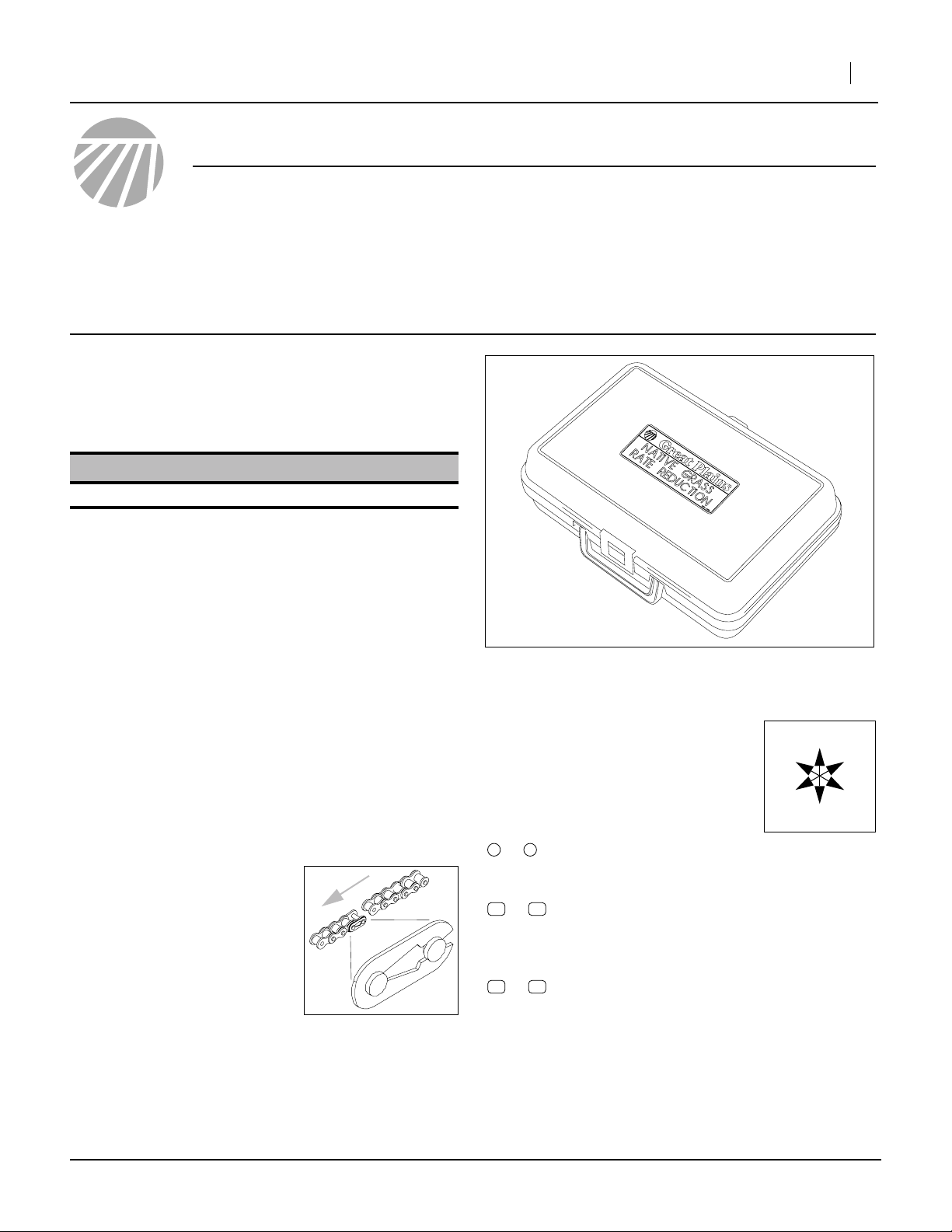
Refer to Figure 1
Remove all contents of the kit case (the case is used to
receive parts removed from the drill).
1. Inventory the new parts per “Parts List” on page 7.
Note: The drill must have Native Grass capability,
Series I or Series II.
Figure 1
Kit Storage Case
28377
Refer to the drill Operator Manual for these steps:
2. Hitch the drill to a suitable tractor.
3. Move the drill to a dry well-lighted location suitable
for disassembly.
4. Lower the drill.
5. Disconnect hydraulic and electrical power to the drill.
Note: Whenever mounting a
chain, make sure the clip at
the removable link is oriented to minimize snags.
Install clip with open end
facing away from direction
of chain travel (often shown
by arrows in the chain
routing diagrams of the
Operator Manual).
©Copyright 2008 Printed 08/25/2008 202-583M
Notations and Conventions
“Left” and “Right” are facing in the
direction of machine travel. An orientation rose in the line art illustrations
shows the directions of: Up, Back, Left,
Down, Front, Right.
1 9
to
12 21
to
51 55
to
callouts identify components in the currently
referenced Figure or Figures. These numbers
may be re-used from page to page.
document-wide callouts reference existing
parts exchanged or temporarily removed. The
descriptions match those in a current drill
Parts Manual.
document-wide callouts reference new parts
from the list on page 7. The descriptions
match those on the cartons, bags or item tags,
as well the current Parts Manual.
R
F
U
B
L
D
Page 2
2 Native Grass Rate Reduction Kit
Installation
Great Plains Mfg., Inc.
Remove Gearbox Cover
Native Grass gearbox location:
605NT Drill left (main gearbox)
3P605NT Drill left (main gearbox)
3P806NT Drill left (main gearbox)
3P1006NT Drill right (dedicated NG gearbox)
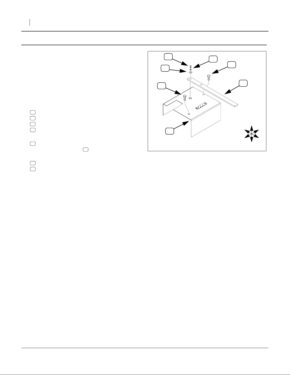
Refer to Figure 2 (depicting a 117-360D cover)
6. At the Native Grass gearbox,
remove and save one set:
16
802-300C HHCS 1/4-28X3/8 GR5
17
804-006C WASHER LOCK SPRING 1/4 PLT
18
804-007C WASHER FLAT 1/4 SAE PLT
12
120-237D GEARBOX SHIFT HANDLE
7. Remove and save two:
15
801-076C SCR SELF TAPPING 3/8X1
that attach the box cover to the gearbox.
8. Remove and save the cover, one of:
11
117-360D CONVENTIONAL GEARBOX COVER
11
151-157D NT GEARBOX COVER
11
Exchange Sprockets
Part locations are slightly different for 6-ft, 8-ft and 10-ft
drills. Each is covered separately. Skip to the page for
your drill:
Page Drill Model
605NT below (step 9, page 3)
3P605NT below (step 9, page 3)
3P806NT step 9, page 4
3P1006NT step 9, page 5
15
16
18
11
17
15
Figure 2
Remove Gearbox Cover
12
R
F
U
B
L
D
25161
202-583M 08/25/2008
Page 3
Great Plains Mfg., Inc.
Exchange 6ft (605NT or 3P605NT) Sprockets
Installation Instructions 3
On 6-foot models, the Native Grass drive shares the single Drive Type gearbox, and uses the left rear output
shaft. The right rear shaft is Main Seed box.
Remove 6ft Gearbox Output Sprocket
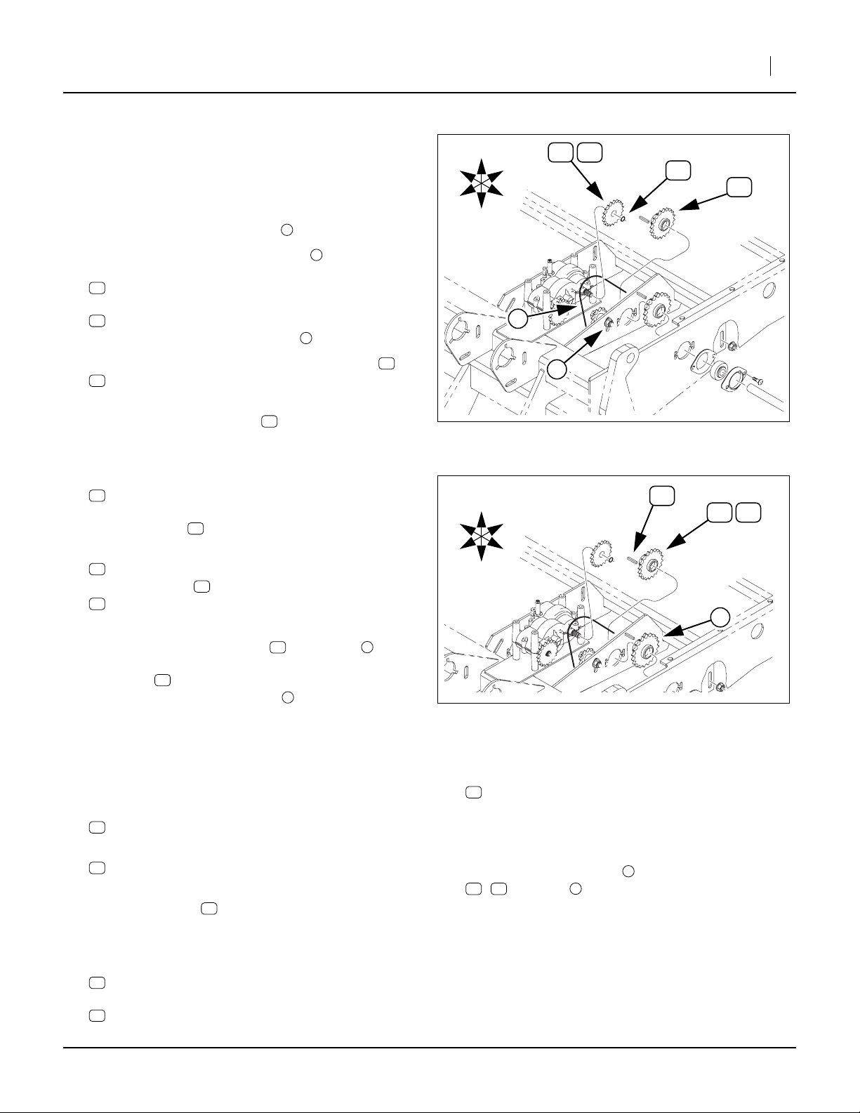
Refer to Figure 3
9. Loosen the bolt and relax idler .
10. Remove the existing 45-pitch chain from both the
existing left rear gearbox output sprocket:
21
808-271C SPKT 40B16 X 36T SPLINE BORE
and from the Native Grass jackshaft input sprocket:
20
808-170C SPKT 40B17 X 3/4BORE W/KW&SS
The chain may be left on the idler .
11. Remove and save the snap ring from sprocket :
14
800-141C SNAP RING EXT F/PEERLESS G.B.
This snap ring is reused during the installation.
12. Remove and save sprocket . Store it in the kit
case for possible future use.
Install New 6ft Output Sprocket
13. Select one new:
53
808-160C SPKT 40B12 X 36T SPLINE BORE
Place this sprocket on the gearbox output shaft
where sprocket was just removed at step 12.
14. Select one saved:
14
800-141C SNAP RING EXT F/PEERLESS G.B.
Secure sprocket on the shaft with the snap ring
14
.
Remove 6ft NG Jackshaft Input Sprocket
The Native Grass jackshaft input and output ends
have otherwise identical 17T keyway sprockets. The
input sprocket is to the right, closer to the gearbox.
Do not remove the output sprocket .
Note: For sufficient clearance, you may need to loosen
other sprocket or bearing collar set screws, and
temporarily slide the jackshaft to the left.
Refer to Figure 4
15. Loosen one or two set screws in the 17T jackshaft
input sprocket:
20
808-170C SPKT 40B17 X 3/4BORE W/KW&SS
16. Remove and save the key:
13
168-127D 3/16 X 1 KEY
The key is re-used during this installation.
17. Remove sprocket . Store the sprocket in the kit
case for possible future use.
Install New 6ft NG Jackshaft Input Sprocket
18. Select one new:
52
808-100C SPKT 40B22 3/4B W/K.W. &SS
Place the sprocket on the jackshaft where sprocket
20
was just removed at step 17.
21
53
20
20
1
2
1
21
21
20 3
3
R
U
B
21
53
14
20
F
L
D
2
1
R
F
Figure 3
6-Foot Gearbox Output Sprocket
U
B
L
13
20
25162
52
D
3
Figure 4
6-Foot NG Jackshaft Input Sprocket
19. Select one saved:
13
168-127D 3/16 X 1 KEY
Insert it in the sprocket and shaft keyways.
If the shaft was moved, slide it back to the right.
20. Secure all set screws.
21. Re-mount 45-pitch chain around new sprockets
52 53 1
, and idler .
22. Adjust chain slack to1⁄4in (6mm).
23. Skip to “Closeout”, step 23, page 6.
2
25162
08/25/2008 202-583M
Page 4

4 Native Grass Rate Reduction Kit
Exchange 8ft (806NT) Sprockets
Continuing from step 8 on page 2. On 8-foot models, the
Native Grass drive shares the single Drive Type gearbox,
and uses the right rear output shaft. The left rear shaft is
Main Seed box.
Remove 8ft Gearbox Output Sprocket
Refer to Figure 5
9. Loosen the bolt and relax idler .
10. Remove the existing 42-pitch chain from both the
existing right rear gearbox output sprocket:
21
808-271C SPKT 40B16 X 36T SPLINE BORE
and from the Native Grass jackshaft input sprocket:
20
808-170C SPKT 40B17 X 3/4BORE W/KW&SS
The chain may be left on the idler .
11. Remove and save the snap ring from sprocket :
14
800-141C SNAP RING EXT F/PEERLESS G.B.
This snap ring is reused during the installation.
12. Remove and save sprocket . Store it in the kit
case for possible future use.
Install New 8ft Gearbox Output Sprocket
13. Select one new:
53
808-160C SPKT 40B12 X 36T SPLINE BORE
Place this sprocket on the gearbox output shaft
where sprocket was just removed at step 12.
14. Select one saved:
14
800-141C SNAP RING EXT F/PEERLESS G.B.
Secure sprocket on the shaft with the snap ring
14
.
Remove 8ft NG Jackshaft Input Sprocket
Refer to Figure 6
15. Loosen one or two set screws in the 17T jackshaft
input sprocket:
20
808-170C SPKT 40B17 X 3/4BORE W/KW&SS
16. Remove and save the key:
13
168-127D 3/16 X 1 KEY
The key is re-used during this installation.
17. Remove sprocket . Store the sprocket in the kit
case for possible future use.
Install New 8ft NG Jackshaft Input Sprocket
18. Select one new:
52
808-100C SPKT 40B22 3/4B W/K.W. &SS
Place the sprocket on the jackshaft where sprocket
20
was just removed at step 17.
19. Select one saved:
13
168-127D 3/16 X 1 KEY
Insert it in the sprocket and shaft keyways.
If the shaft was moved, slide it back to the right.
20. Secure all set screws.
21
53
20
1
2
1
21
21
Great Plains Mfg., Inc.
14
21
53
1
20
U
R
2
F
D
Figure 5
8-Foot Gearbox Output Sprocket
28340
2
52
1
20
Figure 6
8-Foot Jackshaft Input Sprocket
21. Re-mount 45-pitch chain around new sprockets
52 53 1
, and idler .
22. Adjust chain slack to1⁄4in (6mm).
23. Skip to “Closeout”, step 23, page 6.
2
13
28340
B
L
202-583M 08/25/2008
Page 5

Great Plains Mfg., Inc.
Exchange 10ft (3P1006NT) Sprockets
Continuing from step 8 on page 2. On 10-foot models,
the Native Grass drive has a dedicated gearbox, at drill
right. The NG drive system uses the right rear output
shaft.
Remove 10ft Gearbox Output Sprocket
Refer to Figure 7
9. Loosen the bolt and relax idler .
10. Remove the existing 42-pitch chain from both the
existing right rear gearbox output sprocket:
21
808-271C SPKT 40B16 X 36T SPLINE BORE
and from the Native Grass jackshaft input sprocket:
20
808-170C SPKT 40B17 X 3/4BORE W/KW&SS
The chain may be left on the idler .
1
2
1
R
U
B
Installation Instructions 5
53
21
14
20
1
2
11. Remove and save the snap ring from sprocket :
14
800-141C SNAP RING EXT F/PEERLESS G.B.
This snap ring is reused during the installation.
12. Remove and save sprocket . Store it in the kit
case for possible future use.
Install New 10ft Gearbox Output Sprocket
13. Select one new:
53
808-160C SPKT 40B12 X 36T SPLINE BORE
Place this sprocket on the gearbox output shaft
where sprocket was just removed at step 12.
14. Select one saved:
14
800-141C SNAP RING EXT F/PEERLESS G.B.
Secure sprocket on the shaft with the snap ring
14
.
Remove 10ft NG Jackshaft Input Sprocket
Refer to Figure 4
15. Loosen one or two set screws in the 17T jackshaft
input sprocket:
20
808-170C SPKT 40B17 X 3/4BORE W/KW&SS
16. Remove and save the key:
13
168-127D 3/16 X 1 KEY
The key is re-used during this installation.
17. Remove sprocket . Store the sprocket in the kit
case for possible future use.
21
53
20
21
21
F
L
D
Figure 7
10-Foot Gearbox Output Sprocket
2
20
52
1
Figure 8
10-Foot Jackshaft Input Sprocket
Install New 10ft NG Jackshaft Input Sprocket
18. Select one new:
52
808-100C SPKT 40B22 3/4B W/K.W. &SS
Place the sprocket on the jackshaft where sprocket
20
was just removed at step 17.
19. Select one saved:
13
168-127D 3/16 X 1 KEY
Insert it in the sprocket and shaft keyways.
If the shaft was moved, slide it back to the right.
20. Secure all set screws.
28298
13
28298
21. Re-mount 45-pitch chain around new sprockets
52 53 1
, and idler .
22. Adjust chain slack to1⁄4in (6mm).
08/25/2008 202-583M
2
Page 6

6 Native Grass Rate Reduction Kit
Great Plains Mfg., Inc.
Closeout
Refer to Figure 9
23. Replace gear box cover and install the two
self-tapping screws .
24. Place the gear box handle so that the sight hole
is over the Drive Type plate, and secure handle with
1
⁄4-28 bolt , washer and lock washer .
25. Return these instructions to the kit case. Store the
case for future use.
16 18 17
11
15
12
3
⁄8in
Using Reduced Seed Rate
15
18
16
11
17
Figure 9
Install Gearbox Cover
15
12
R
F
U
B
L
D
25161
The components installed reduce the population rate, for
Native Grass only, by 42%, which is an adjustment factor
of 0.58.
The Seed Rate Reduction kit does not affect the population rates of:
• main seed box
• small seeds box
Not all Seed Rate manuals include both standard and
Reduced Rate charts.
Use your existing Seed Rate charts for native grass, and
apply the correction factor.
Maintenance
Re-check chain slack after first few hours or operation,
due to seating.
The installation of this kit requires no other changes to
the regular maintenance of the drill as specified in the
Operator’s Manual.
For Series I Native Grass Seeding
The chart rates, in pounds-per-acre, need to be adjusted
by multiplying by 0.58.
ReducedPoundsPerAcre ChartPoundsPerAcre 0.58×=
For Series II Native Grass Seeding
The chart rates, in cup-revolutions-per-acre, need to be
adjusted by multiplying by 0.58.
ReducedCupRevsPerAcre ChartCupRevsPerAcre 0.58×=
202-583M 08/25/2008
Page 7

Great Plains Mfg., Inc.
Installation Instructions 7
Appendix
Parts List
202-580A Native Grass Rate Reduction Kit
Your kit includes:
Callout Part Number Quantity Description
51
52
53
54
55
Abbreviations
EXT External SAE Society of Automotive Engineers (standard)
GR5 Grade 5 SCR Screw
HHCS Hex Head Cap Screw SPKT Sprocket
KW Keyway SS Set Screw
NG Native Grass W/ with
PLT Plated X by
202-582M 1
808-100C 1
808-160C 1
817-814C 1
817-814C 1
MANUAL 706/1006 RATE REDUCTION (this manual)
SPKT 40B22 3/4B W/K.W. &SS
SPKT 40B12 X 36T SPLINE BORE
CASE, PLASTIC 12X8X3 3/4
DECAL, NG RATE REDUCTION
08/25/2008 202-583M
Page 8

8 Native Grass Rate Reduction Kit
Great Plains Mfg., Inc.
Great Plains Manufacturing, Inc.
Corporate Office: PO Box 5060
Salina, KS 67402-5060 USA
202-583M 08/25/2008
 Loading...