

Great Plains 3P600 Operator Manual
Table of Contents Index
3-Point 5-Foot and 6-Foot Drills
Operator Manual
3P500, 3P500V and 3P600
Manufacturing, Inc.
www.greatplainsmfg.com
Read the operation manual entirely. When you see this symbol, the
subsequent instructions and warnings are serious - follow without
exception. Your life and the lives of others depend on it!
18556
Illustrations may show optional equipment not supplied with standard unit, and may
show 3P500, 3P500V or 3P600 models.
ORIGINAL INSTRUCTIONS
© Copyright 2011 Printed 2011-10-21 118-794M
Table of Contents Index
EN
Rev. B

Table of Contents Index
Table of Contents Index

Great Plains Manufacturing, Inc. Cover Index iii
Table of Contents
Important Safety Information ......................................1
Safety Decals .................................................................5
Introduction ..................................................................9
Description of Unit ..........................................................9
Intended Usage ..........................................................9
Models Covered .........................................................9
Document Family........................................................9
Using This Manual........................................................10
Owner Assistance ........................................................10
Preparation and Setup ...............................................11
Pre-Setup Checklist......................................................11
Hitching Tractor to Drill.................................................11
Electrical Connection (Option)......................................12
Height and Leveling the Drill ........................................12
Operation Instructions...............................................13
Pre-Start Checklist .......................................................13
Transporting .................................................................14
Use an Adequate Tractor (3-Point)...........................14
3P500 Example Weights .......................................... 14
3P500V Example Weights........................................ 14
3P600 Example Weights .......................................... 14
Loading Seed ............................................................... 15
Main Seed Box Loading ...........................................15
Loading Small Seeds Box ........................................15
Acremeter Operation ....................................................16
Normal Operating Sequence....................................16
Dormant Display.......................................................16
Field Operation.............................................................17
Parking .........................................................................17
Storage.........................................................................17
Adjustments................................................................18
Adjusting 3-Point Height...............................................19
00 Series Row Unit Adjustments..................................20
Opener Springs ........................................................21
Disc Blade Adjustments ........................................... 22
Disc Scraper Adjustment.......................................... 23
Seed Firmer Adjustments......................................... 23
Seed-Lok® Lock-Up (Option) ............................... 23
Keeton® Seed Firmer Adjustment (Option) .......... 24
Small Seeds Tube Adjustment (Option)................... 24
Opener Depth (Press Wheel Height) ....................... 25
Troubleshooting......................................................... 26
Maintenance and Lubrication ................................... 28
Maintenance ................................................................ 28
Seed Clean-Out ....................................................... 29
Main Box Clean-Out............................................. 29
Small Seeds Box Clean-Out ................................ 29
Seed Flap Replacement........................................... 30
Current Drill Model Flap .......................................30
Older Drill Model Flap .......................................... 30
Chain Maintenance .................................................. 31
Chain Slack .......................................................... 31
Gearbox Maintenance..............................................31
Lubrication and Scheduled Maintenance..................... 32
Options ....................................................................... 34
Seed-Lok® Seed Firmer........................................... 37
Appendix A - Reference Information........................ 39
Specifications and Capacities: 3P500 and 3P600 ....... 39
Specifications and Capacities: 3P500V ....................... 40
Tire Pressures.............................................................. 40
Torque Values Chart.................................................... 41
Drive System Diagrams ............................................... 42
Appendix B - Pre-Delivery......................................... 44
Appendix C - Accessory Installation........................ 46
Carbide Disc Scraper Installation................................. 46
Warranty ..................................................................... 51
Index............................................................................ 53
© Copyright 2000, 2002, 2008, 2011 All rights Reserved
Great Plains Manufacturing, Inc. provides this publication “as is” without warranty of any kind, either expressed or implied. While every precaution has been
taken in the preparation of this manual, Great Plains Manufacturing, Inc. assumes no responsibility for errors or omissions. Neither is any liability assumed for
damages resulting from the use of the information contained herein. Great Plains Manufacturing, Inc. reserves the right to revise and improve its products as
it sees fit. This publication describes the state of this product at the time of its publication, and may not reflect the product in the future.
2011-10-21 Cover Index 118-794M
Trademarks of Great Plains Manufacturing, Inc. include: Singulator Plus, Swath Command, Terra-Tine.
Registered Trademarks of Great Plains Manufacturing, Inc. include:
Air-Pro, Clear-Shot, Great Plains, Land Pride, MeterCone, Nutri-Pro, Seed-Lok, Solid Stand, Whirlfilter, Yield-Pro.
Brand and Product Names that appear and are owned by others are trademarks of their respective owners.
Printed in the United States of America

iv 3P500, 3P500V & 3P600 Table of Contents Index Great Plains Manufacturing, Inc.
118-794M Table of Contents Index 2011-10-21
Great Plains Manufacturing, Inc. Table of Contents Index 1
Important Safety Information
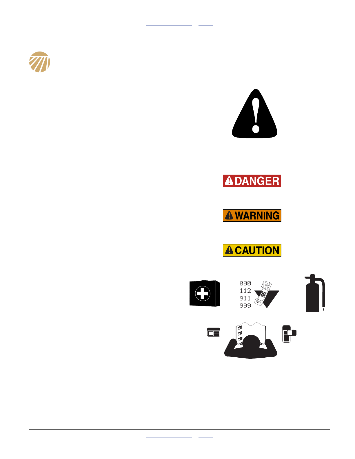
Look for Safety Symbol
The SAFETY ALERT SYMBOL indicates there is a
potential hazard to personal safety involved and extra
safety precaution must be taken. When you see this
symbol, be alert and carefully read the message that
follows it. In addition to design and configuration of
equipment, hazard control and accident prevention are
dependent upon the awareness, concern, prudence and
proper training of personnel involved in the operation,
transport, maintenance and storage of equipment.
Be Aware of Signal Words
Signal words designate a degree or level of hazard
seriousness.
DANGER, and the color Safety Red, indicate an
imminent hazard which, if not avoided, will result in death
or serious injury. This signal word is limited to the most
extreme situations, typically for machine components
that, for functional purposes, cannot be guarded.
WARNING, and the color Safety Orange, indicate a
potential hazard which, if not avoided, could result in
death or serious injury, and includes hazards that are
exposed when guards are removed. It may also be used
to alert against unsafe practices.
CAUTION, and the color Safety Yellow, indicate a
potential hazard which, if not avoided, may result in
minor or moderate injury. It may also be used to alert
against unsafe practices.
Prepare for Emergencies
▲ Be prepared if a fire starts
▲ Keep a first aid kit and fire extinguisher handy.
▲ Keep emergency numbers for doctor, ambulance, hospital
and fire department near phone.
Be Familiar with Safety Decals
▲ Read and understand “Safety Decals” on page 5,
thoroughly.
▲ Read all instructions noted on the decals.
▲ Keep decals clean. Replace damaged, faded and illegible
decals.
2011-10-21 Table of Contents Index

2 3P500, 3P500V & 3P600 Table of Contents Index Great Plains Manufacturing, Inc.
Wear Protective Equipment
▲ Wear protective clothing and equipment.
▲ Wear clothing and equipment appropriate for the job. Avoid
loose-fitting clothing.
▲ Because prolonged exposure to loud noise can cause
hearing impairment or hearing loss, wear suitable hearing
protection such as earmuffs or earplugs.
▲ Because operating equipment safely requires your full
attention, avoid wearing entertainment headphones while
operating machinery.
Handle Chemicals Properly
Agricultural chemicals can be dangerous. Improper use
can seriously injure persons, animals, plants, soil and
property.
▲ Do not use liquid seed treatments with the drill.
▲ Read and follow chemical manufacturer’s instructions.
▲ Wear protective clothing.
▲ Handle all chemicals with care.
▲ Avoid inhaling smoke from any type of chemical fire.
▲ Never drain, rinse or wash dispensers within 100 feet
(30 m) of a freshwater source, nor at a car wash.
▲ Store or dispose of unused chemicals as specified by
chemical manufacturer.
▲ Dispose of empty chemical containers properly. Laws
generally require power rinsing or rinsing three times,
followed by perforation of the container to prevent re-use.
Use an Adequate Tractor
▲ Ensure that the tractor is rated for, and correctly ballasted
for the drill’s 3-point loading. Check that drill plus ballast
does not exceed the tractor’s capability.
▲ Avoid transport with material loaded in boxes.
Keep Riders Off Machinery
Riders obstruct the operator’s view. Riders could be
struck by foreign objects or thrown from the machine.
▲ Never allow children to operate equipment.
▲ Keep all bystanders away from machine during operation.
Use Safety Lights and Devices
Slow-moving tractors and towed implements can create
a hazard when driven on public roads. They are difficult
to see, especially at night.
▲ Use flashing warning lights and turn signals whenever
driving on public roads.
▲ Use lights and devices if provided with implement.
Table of Contents Index 2011-10-21

Great Plains Manufacturing, Inc. Table of Contents Index Important Safety Information 3
Transport Machinery Safely
Maximum transport speed for the implement on its own
tires is 20 mph (30 kph). Rough terrain may require a
slower speed. Sudden braking can cause a towed load to
swerve and upset.
▲ Do not exceed 20 mph (30 kph). Travel only at a speed
which allows adequate control of steering and stopping.
▲ Comply with state and local laws.
▲ Carry reflectors or flags to mark drill in case of breakdown
on the road.
▲ 3-point implements reduce weight on steering tires. Verify
that tractor is correctly ballasted. Watch for signs of poor
steering traction.
Shutdown and Storage
▲ Park on level ground.
▲ Unhitch and store the drill in an area where children
normally do not play.
Tire Safety
Tire changing can be dangerous and should be
performed by trained personnel using correct tools and
equipment.
▲ When inflating tires, use a clip-on chuck and extension hose
long enough for you to stand to one side–not in front of or
over tire assembly. Use a safety cage if available.
▲ When removing and installing wheels, use wheel-handling
equipment adequate for weight involved.
2011-10-21 Table of Contents Index

4 3P500, 3P500V & 3P600 Table of Contents Index Great Plains Manufacturing, Inc.
Practice Safe Maintenance
▲ Understand procedure before doing work. Use proper
tools and equipment. Refer to this manual.
▲ Work in a clean, dry area.
▲ Lower the drill, put tractor in park, turn off engine, and
remove key before performing maintenance. If work must
be performed with implement raised, use blocks or
jackstands rated for the drill weight.
▲ Make sure all moving parts have stopped and all system
pressure is relieved.
▲ Allow drill to cool completely.
▲ Disconnect lighting connector before servicing or
adjusting electrical systems.
▲ Welding: Disconnect battery ground. Avoid fumes from
heated paint.
▲ Inspect all parts. Make sure parts are in good condition
and installed properly.
▲ Remove buildup of grease, oil or debris.
▲ Remove all tools and unused parts from drill before
operation.
Safety At All Times
Thoroughly read and understand the instructions in this
manual before operation. Read all instructions noted on
the safety decals.
▲ Be familiar with all drill functions.
▲ Operate machinery from the driver’s seat only.
▲ Do not leave drill unattended with tractor engine running.
▲ Do not stand between the moving tractor and drill during
hitching.
▲ Keep hands, feet and clothing away from power-driven
parts.
▲ Wear snug-fitting clothing to avoid entanglement with
moving parts.
▲ Make sure all persons are clear of working area.
Table of Contents Index 2011-10-21
Great Plains Manufacturing, Inc. Table of Contents Index Important Safety Information 5
Safety Decals
Safety Reflectors and Decals
Your implement comes equipped with all lights, safety
reflectors and decals in place. They were designed to
help you safely operate your implement.
▲ Read and follow decal directions.
▲ Keep lights in operating condition.
▲ Keep all safety decals clean and legible.
▲ Replace all damaged or missing decals. Order new decals
from your Great Plains dealer. Refer to this section for
proper decal placement.
▲ When ordering new parts or components, also request
corresponding safety decals.
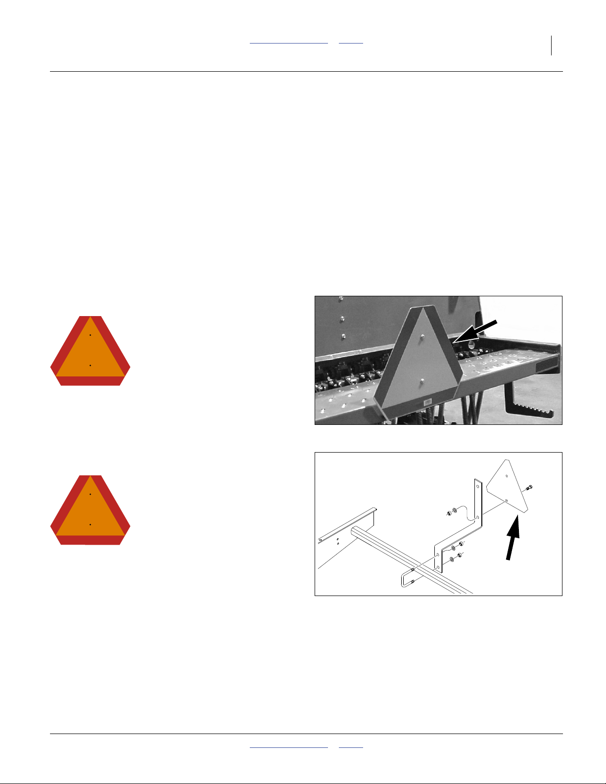
Reflector: Slow Moving Vehicle (SMV)
818-055C
To install new decals:
1. Clean the area on which the decal is to be placed.
2. Peel backing from decal. Press firmly on surface,
being careful not to cause air bubbles under decal.
18490
Models 3P500 and 3P600
At center of walkboard;
1 total
See transport topic on page 14.
Reflector: Slow Moving Vehicle (SMV)
818-055C
Model 3P500V
At center of walkboard;
1 total
See transport topic on page 14.
32717
2011-10-21 Table of Contents Index
6 3P500, 3P500V & 3P600 Table of Contents Index Great Plains Manufacturing, Inc.
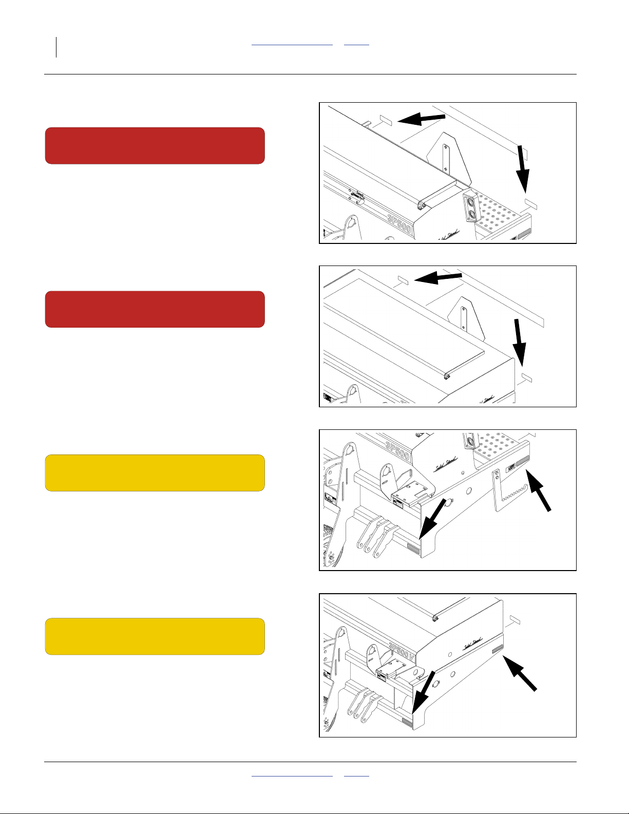
Reflectors: Red
838-266C
Models 3P500 and 3P600 (standard) Model 3P500V (Option)
On rear face of walkboard, left and right ends;
2 total
See transport topic on page 14.
Reflectors: Red
838-266C
Model 3P500V (Standard)
On rear face of seed box, left and right ends;
2 total
See transport topic on page 14.
32713
32727
Reflectors: Amber
838-265C
Models 3P500 and 3P600
On outside face of side frames, at rear below walkboard
face of walkboard, and on front face of lower front tool
bar, at ends;
4 total
See transport topic on page 14.
Reflectors: Amber
838-265C
Model 3P500V
On outside face of side frames, at rear, and
on front face of lower front tool bar, at ends;
4 total
See transport topic on page 14.
32713
32727
Table of Contents Index 2011-10-21
Great Plains Manufacturing, Inc. Table of Contents Index Important Safety Information 7
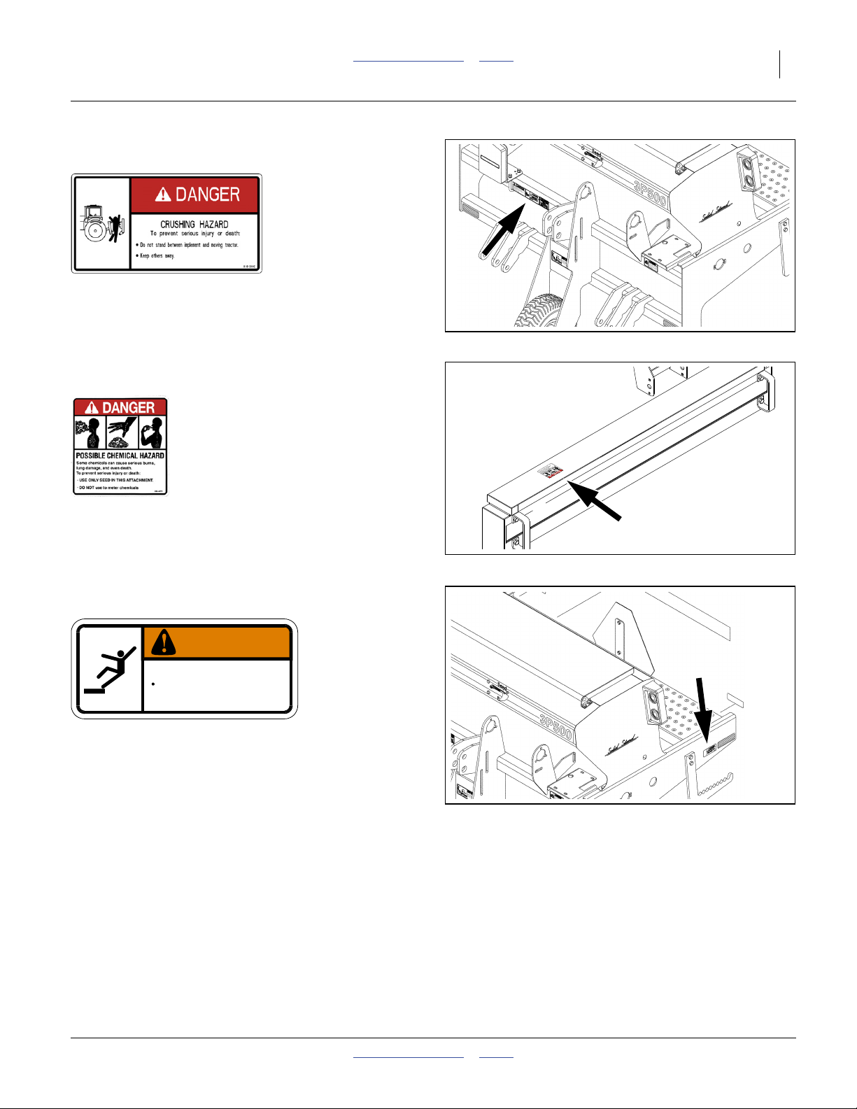
Danger: Hitch Crush
818-590C
All Models
Front face, top front tool bar, right of center;
32713
2 total
Danger: Possible Chemical Hazard (Option)
838-467C
(with Small Seeds Option only)
Under lid;
1 total
Warning: Falling Hazard
838-102C
WARNING
To avoid serious injury or death:
Watch your step when climbing ladder or
walking on walkboard.
Models 3P500 and 3P600 (standard) Model 3P500V (Option)
On side frames at walkboard ends;
2 total
See “Loading Seed” on page 15.
838-102C
32696
32713
2011-10-21 Table of Contents Index
8 3P500, 3P500V & 3P600 Table of Contents Index Great Plains Manufacturing, Inc.
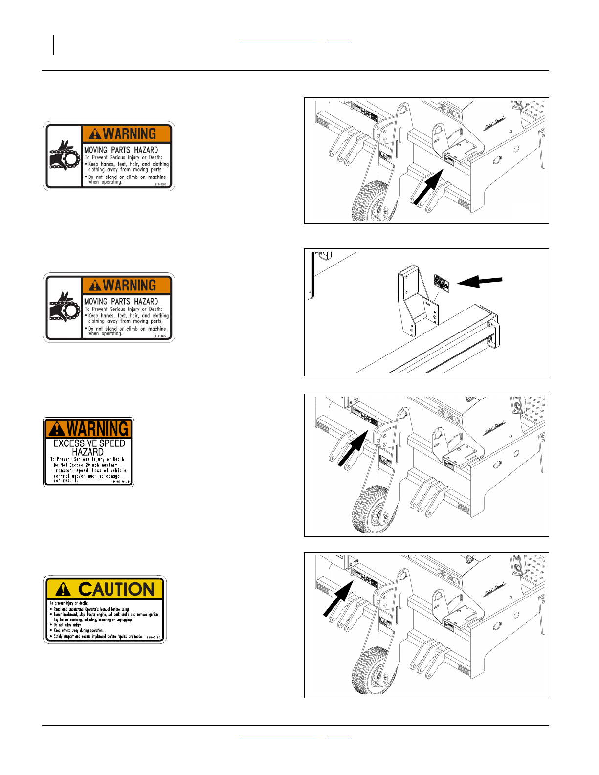
Warning: Moving Parts (standard)
818-860C
All Models
On front face, upper front frame tube, below gearbox;
1 total
32713
Warning: Moving Parts (Option)
818-860C
(with Small Seeds Option only)
On front face, upper front frame tube, below gearbox;
1 total
Warning: Speed
818-337C
All Models
On front face, upper front frame tube, right of center;
1 total
See transport topic on page 14.
Caution: General
818-719C
32696
32713
All Models
On front face, upper front frame tube, right of center;
1 total
See “Important Safety Information” on page 1.
Table of Contents Index 2011-10-21
32713
Great Plains Manufacturing, Inc. Table of Contents Index 9
Introduction
Great Plains welcomes you to its growing family of new
product owners. Your no-till drill has been designed with
care and built by skilled workers using quality materials.
Proper setup, maintenance, and safe operating practices
will help you get years of satisfactory use from the
machine.
Description of Unit
The 3P500, 3P500V and 3P600 are 3-point seeding
implements. The drill has straight arm, double disc
00 Series openers. The opener discs make a seed bed,
and seed tubes mounted between the discs place seed
in the furrow. Press wheels following the opener discs
close the furrow and gauge opener seeding depth.
A T-handle on the opener body makes seeding depth
adjustments.
The metering system is driven from the gauge wheel.
Seeding rates are set by rate adjustment handles and a
Drive Type gearbox for the main seed box.
Intended Usage
Use this implement to seed production-agriculture crops
in conventional or minimum tillage applications.
Models Covered
This manual applies to Great Plains drill models:
3P500-0775 7-Row 7.5 in. (19.1 cm)
3P500-0906 9-Row 6 in. (15.2 cm)
3P500V-0775 7-Row 7.5 in. (19.1 cm)
3P500V-0872 8-Row 7.25 in. (18.4 cm)
3P500V-0906 9-Row 6 in. (15.2 cm)
3P600-0975 9-Row 7.5 in. (19.1 cm)
3P600-1106 11-Row 6 in. (15.2 cm)
Standard drills have a Main Seed box. Small Seeds
capability may be added to Models 3P500 or 3P600.
The Model 3P500V (Vineyard) is a low-profile version of
the 3P500.
Document Family
118-794M Operator Manual (this document)
118-794P Parts Manual
118-794B Seed Rate Manual
152-314M Electronic Acremeter Manual
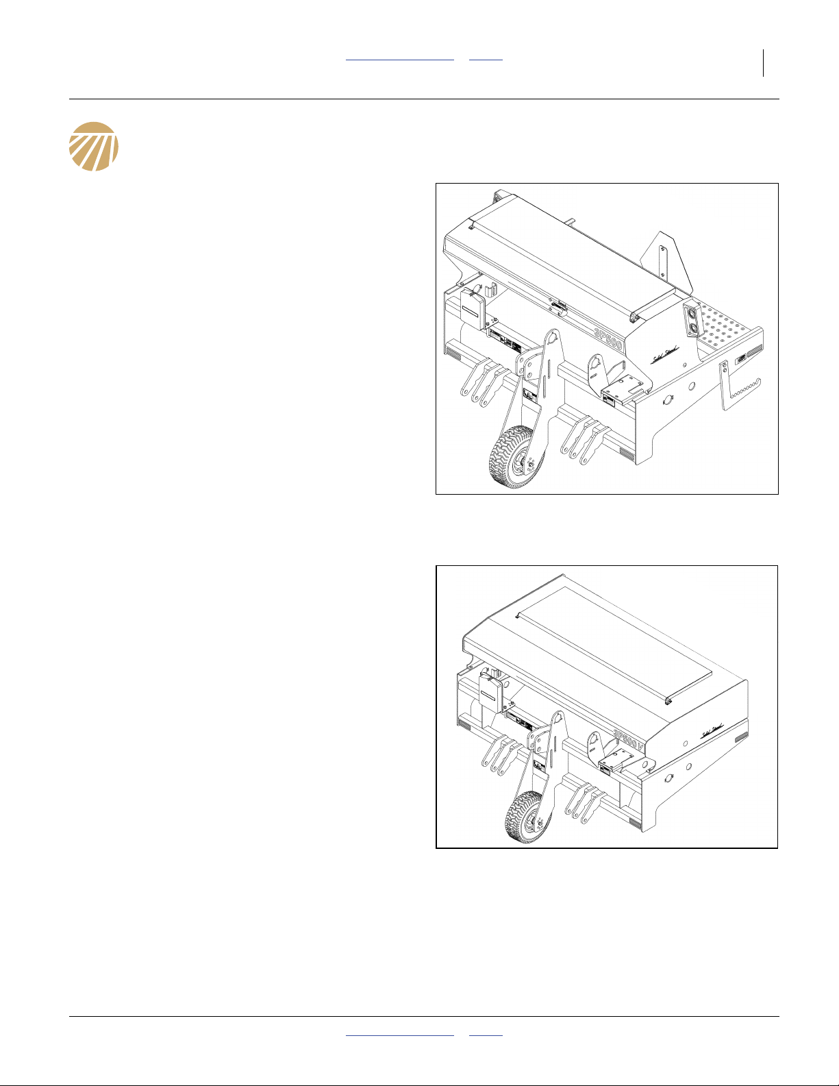
Figure 1
3P500 No-Till Drill
Figure 2
3P500V No-Till Drill
32713
32727
2011-10-21 Table of Contents Index
10 3P500, 3P500V & 3P600 Table of Contents Index Great Plains Manufacturing, Inc.
Using This Manual
This manual familiarizes you with safety, assembly,
operation, adjustments, troubleshooting, and
maintenance. Read this manual and follow the
recommendations to help ensure safe and efficient
operation.
Right-hand and left-hand as used in
this manual are determined by facing
the direction the machine will travel
while in use unless otherwise stated.
An orientation rose in some line art
illustrations shows the directions of:
Up, Back, Left, Down, Front, Right.
U
R
F
D
B
L
Identifies an Economic (not a Safety) Risk:
NOTICE provides a crucial point of information related to the
current topic. Read and follow the instructions to avoid damage
to equipment and ensure desired field results.
Note: This form sets off useful information related to the
current topic, or forestalls possible
misunderstanding.
The information in this manual is current at printing.
Some parts may change to assure top performance.
Owner Assistance
If you need customer service or repair parts, contact a
Great Plains dealer. They have trained personnel, repair
parts and equipment specially designed for Great Plains
products.
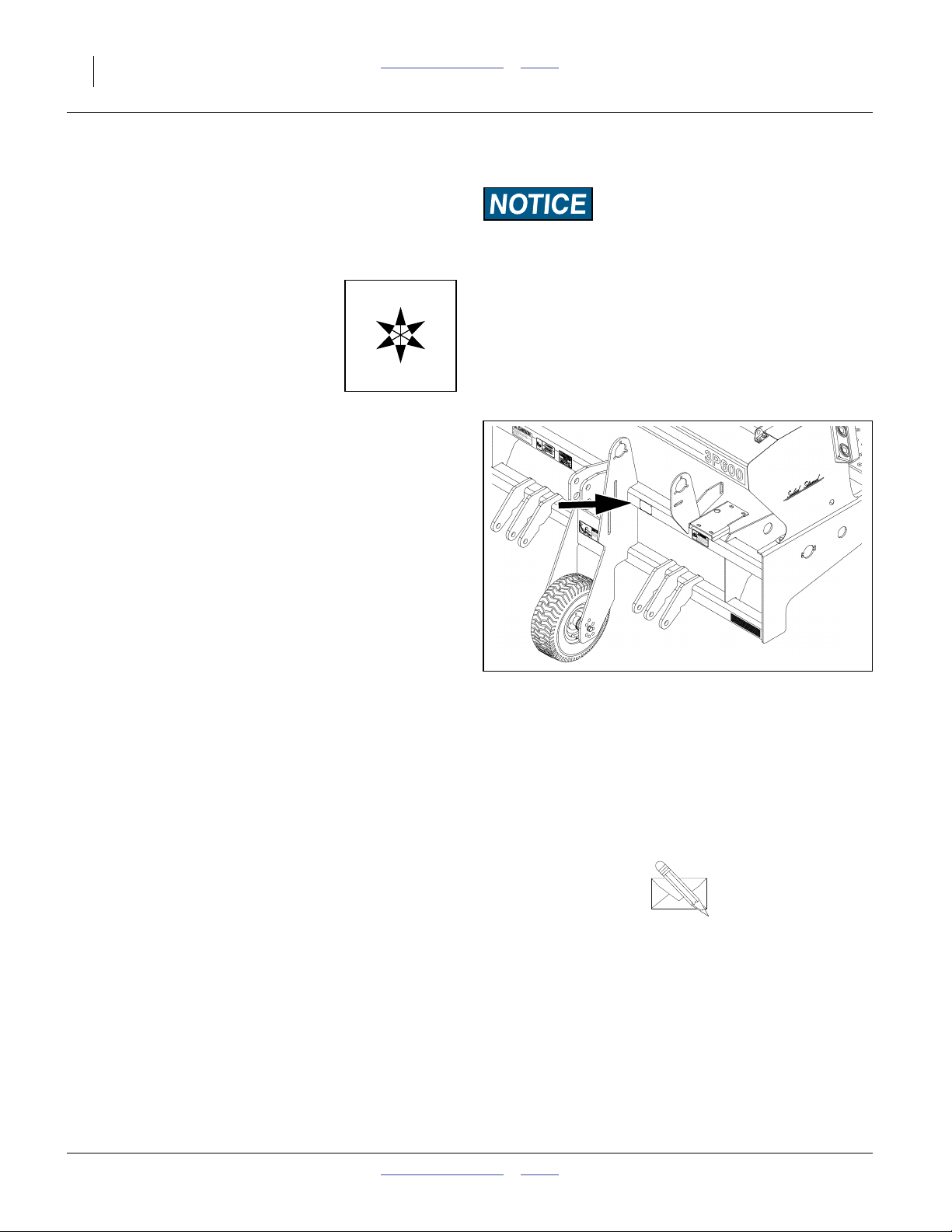
Refer to Figure 3
Your machine’s parts were specially designed and
should only be replaced with Great Plains parts. Always
use the serial and model number when ordering parts
from your Great Plains dealer. The serial-number plate is
located on the upper front frame tube, left of center.
Record your drill model and serial number here for quick
reference:
Model Number:__________________________
Serial Number: __________________________
Figure 3
Serial Number Location
18709
Your Great Plains dealer wants you to be satisfied with
your new machine. If you do not understand any part of
this manual or are not satisfied with the service received,
please take the following actions.
1. Discuss the matter with your dealership service
manager. Make sure they are aware of any problems
so they can assist you.
2. If you are still unsatisfied, seek out the owner or
general manager of the dealership.
Table of Contents Index 2011-10-21
For further assistance write to:
Product Support
Great Plains Mfg. Inc., Service Department
PO Box 5060
Salina, KS 67402-5060
gp_web_cs@greatplainsmfg.com
785-823-3276
Great Plains Manufacturing, Inc. Table of Contents Index 11
Preparation and Setup
This section helps you prepare your tractor and drill for
use. Before using the drill in the field, you must hitch the
drill to a suitable tractor and also setup the drill.
Pre-Setup Checklist
1. Verify that dealer pre-delivery is complete (page 44)
and optional accessories are installed (page 46).
2. Read and understand “Important Safety
Information” on page 1.
3. Check that all working parts are moving freely, bolts
are tight, and cotter pins are spread.
4. Check that all grease fittings are in place and
lubricated. See “Lubrication and Scheduled
Maintenance” on page 32.
5. Check that all safety decals and reflectors are
correctly located and legible. Replace if damaged.
See “Safety Decals” on page 5.
6. Inflate tires and tighten wheel bolts as at “Tire
Pressures” on page 40.
Hitching Tractor to Drill
Crushing Hazard:
You may be severely injured or killed by being crushed
between the tractor and drill. Do not stand or place any part of
your body between drill and moving tractor. Stop tractor
engine and set park brake before installing the hitch pin.
Certain Machine Damage:
Remove tractor draw bar before hitching. The drill drive wheel
will be damaged if drawbar is not removed.
1. Raise or lower tractor 3-point arms as needed and
pin lower arms to drill.
2. Pin upper arm to drill.
3. Slowly raise drill. Watch for cab interference.
4. Adjust top 3-point link so the top edge of drill box is
parallel with the ground when drilling.
Note: Do not use link to adjust opener depth. For opener
adjustments, refer to “Opener Depth (Press
Wheel Height)” on page 25. Set your tractor
3-point draft control to Float position for planting.
Equipment Damage Risk:
Due to interference with the gauge wheel assembly, drill
models 3P500, 3P500V and 3P600 are not compatible with
Great Plains accessory hitches CPH, PFH and SSH, nor with
the Great Plains hitch set-back kit.
2011-10-21 Table of Contents Index
12 3P500, 3P500V & 3P600 Table of Contents Index Great Plains Manufacturing, Inc.
Electrical Connection (Option)
Refer to Figure 4
5. Plug drill electrical lead into tractor seven-pin
connector. If your tractor is not equipped with an
SAE-J560B seven-pin connector, contact your dealer
for installation.
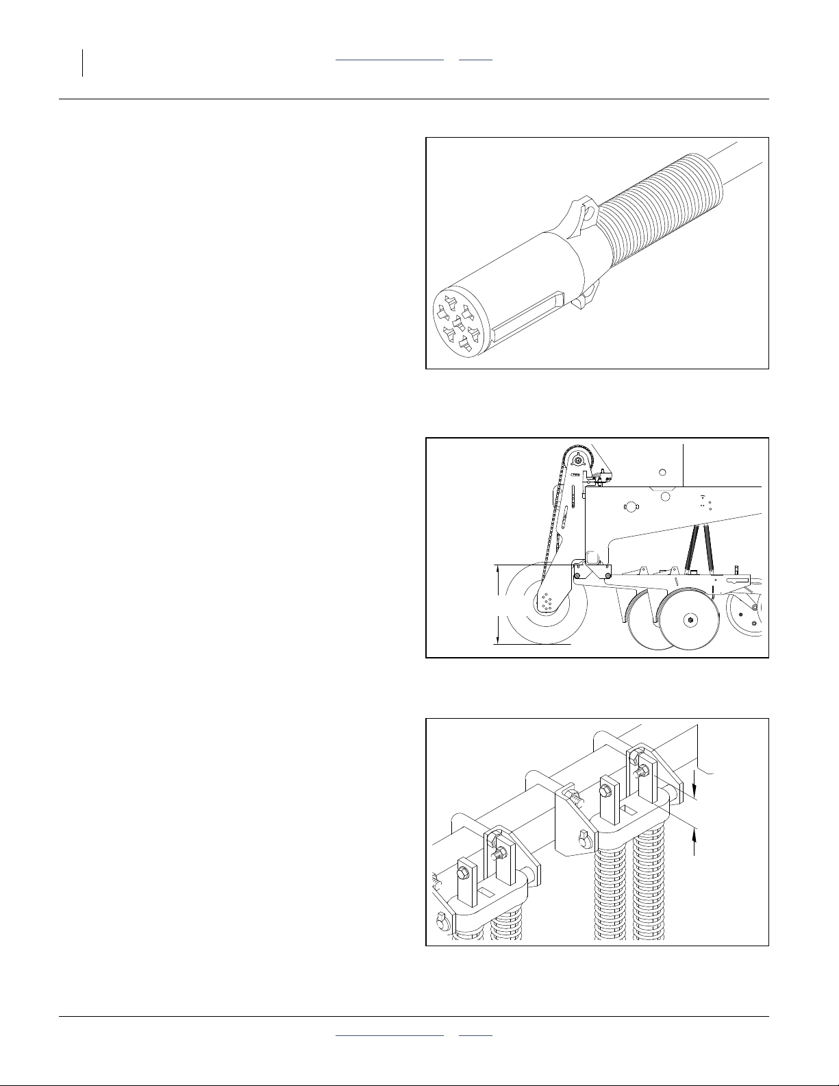
Height and Leveling the Drill
Refer to Figure 5 and Figure 9 on page 19
1. Initially adjust drill so opener tool bar runs
18 in. (45.7 cm) above ground when drill is lowered
in the field.
2. The drive wheel should be in the fourth mounting
hole from the top (factory setting).
Note: The drive may need to be adjusted due to ground
conditions.
3. Level the drill frame with the top 3-point link.
Refer to Figure 6
4. When drill is level, the gap between the spring-rod
casting and the cross bolt will be about 2 inches.
This is a general dimension that will vary with the
amount of down pressure required for your planting
conditions.
18 in. (45.7 cm)
Figure 4
Lighting Connector
Figure 5
Initial Field Height
26467
18545
2.0 in.
5.1 cm
Figure 6
Initial Spring Rod Reveal
Table of Contents Index 2011-10-21
10548
Great Plains Manufacturing, Inc. Table of Contents Index 13
Operation Instructions
This section covers general operating procedures.
Experience, machine familiarity and the following
information will lead to efficient operation and good
working habits. Always operate farm machinery with
safety in mind.
Pre-Start Checklist
1. Carefully read “Important Safety Information”
starting on page 1.
2. Lubricate drill per “Lubrication and Scheduled
Maintenance” starting on page 32.
3. Check all tires for proper inflation. See “Tire
Pressures” on page 40.
4. Check all bolts, pins and fasteners. See “Torque
Values Chart” on page 41.
5. Check drill for worn or damaged parts. Repair or
replace faulty parts before going to the field.
6. Rotate both drive wheel to verify that the drive and
meters are working properly and free from foreign
material.
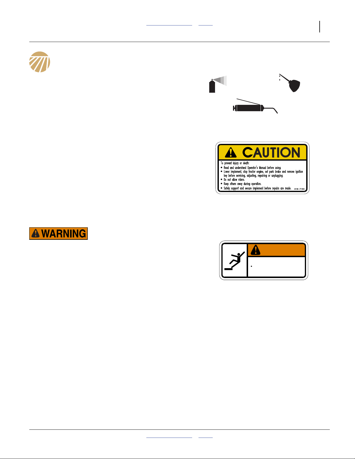
Falling Hazard:
Watch your step when walking on drill steps and walkboard.
Falling from drill could cause severe injury or death.
WARNING
To avoid serious injury or death:
Watch your step when climbing ladder or
walking on walkboard.
838-102C
2011-10-21 Table of Contents Index
14 3P500, 3P500V & 3P600 Table of Contents Index Great Plains Manufacturing, Inc.
Transporting
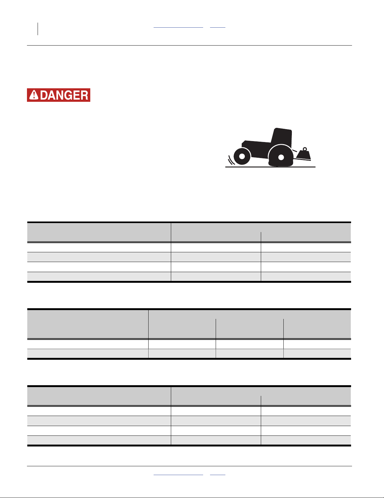
Use an Adequate Tractor (3-Point)
Loss of Control Hazard:
Insufficient weight on tractor steering tires can dangerously
reduce steering authority, particularly during acceleration and
ascending hills. You can lose directional control entirely,
which could result in a major accident, serious injury, or
death. Adding too much ballast could lead to brake or other
mechanical failures, tire failures and loss of control.
▲ Ensure that the tractor is rated for, and correctly ballasted
for the drill’s 3-point loading. Check that drill plus ballast
does not exceed the tractor’s capability.
▲ Avoid transport with material loaded in boxes.
The total drill weight and center of gravity vary with drill
configuration and material load. See tables below.
3P500 Example Weights
Standard Drill (Main Seed Only), Empty
Standard Drill with Main Seed Loaded
Drill with Small Seeds option, Empty
Drill with Main and Small Seeds Loaded
3P500V Example Weights
Standard Drill (Main Seed Only), Empty
Standard Drill with Main Seed Loaded
3P600 Example Weights
Standard Drill (Main Seed Only), Empty
Standard Drill with Main Seed Loaded
Drill with Small Seeds option, Empty
Drill with Main and Small Seeds Loaded
3P500 Configuration
7-Row 7.5 inch (19.1 cm)
1100 lbs. (500 kg) 1300 lbs. (590 kg)
1700 lbs. (770 kg) 1900 lbs. (860 kg)
1170 lbs. (530 kg) 1370 lbs. (620 kg)
1840 lbs. (840 kg) 2040 lbs. (930 kg)
3P500V Configuration
7-Row 7½ in. 8-Row 7¼ in.
(19.1 cm) (18.4 cm) (15.2 cm)
1100 lbs. (500 kg) 1200 lbs. (540 kg) 1300 lbs. (590 kg)
1700 lbs. (270 kg) 1800 lbs. (270 kg) 1900 lbs. (270 kg)
3P600 Configuration
9-Row 7.5 inch (19.1 cm)
1380 lbs. (630 kg) 1500 lbs. (680 kg)
2100 lbs. (950 kg) 2220 lbs. (1010 kg)
1470 lbs. (670 kg) 1590 lbs. (720 kg)
2270 lbs. (1030 kg) 2390 lbs. (1090 kg)
9-Row 6 inch (15.2 cm)
32807D
9-Row 6 in.
32807E
11-Row 6 inch (15.2 cm)
32807G
Table of Contents Index 2011-10-21
 Loading...