

Page 1

Part Lists Great Plains Manufacturing, Inc. 1
Caster Wheel Update Kit
3P806NT and 3P1006NT Drills
Used with:
• 3P806NT (S/N A1034V-)
• 3P1006NT (S/N A1047-)
General Information
These instructions explain how to install a Caster Wheel
Update Kit. One kit updates an entire drill:
Kit Kit Description
124-047A Caster Wheel Update Kit
Related Documents
Have the Operator and Parts Manuals at hand.
151-143M Operator, 3P806NT
151-143P Parts, 3P806NT
151-144M Operator, 3P1006NT
151-144P Parts, 3P1006NT
When you see this symbol, the subsequent instructions
and warnings are serious - follow without exception.
Your life and the lives of others depend on it!
Tools Required
• basic hand tools
• grease and grease gun
Work Location
1. Move the implement to a location with:
• flat, smooth surface
• adequate illumination
Prepare Drill
2. Block the tires and install the parking jack.
3. Disconnect all hydraulic and electrical conections at
the hitch. Secure hoses and cables to prevent
ground contact.
Notations and Conventions
U
F
L
D
“Left” and “Right” are facing in the
direction of machine travel. An orienta-
R
tion rose in the line art illustrations
shows the directions of Left, Right,
Front, Back, Up, Down.
B
Figure 1
Caster Wheel Update Kit
High Pressure Fluid Hazard:
Releive pressure from all lines before
working on hydraulic connections. Wear
eye protection and gloves when opening hydraulic
connections. Open connections slowly. Use a piece of
paper or cardboard, NOT BODY PARTS, to check for leaks. Escaping
fluid under pressure can have sufficient pressure to penetrate the skin
causing serious injury. If an accident occurs, seek immediate medical
assistance from a physician familiar with this type of injury.
29969
Call-Outs
1 9
to
11
to
51
Single-digit callouts identify components in
the currently referenced Figure. These numbers may be reused for different items from
page to page.
21
Two-digit callouts in the range 11 to 21 reference new parts from the list on page 4.
This callout references an existing part from
page 4.
© Copyright 2009 Printed 12/22/2009 Part Lists 124-049M
Page 2
2 Great Plains Manufacturing, Inc. Front Page Part Lists Caster Wheel Update
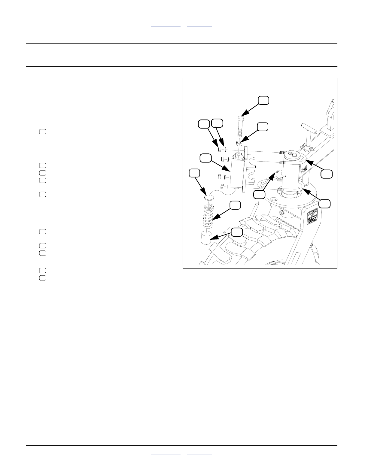
Caster Wheel Update
Installation
Refer to Figure 2
These instructions are for both caster wheels.
1. Remove existing straight grease zerk from lift assist
arm.
2. Replace with 90 degree zerk from kit:
15
800-073C GREASE ZERK 1/4-28 X90-DEG
3. Using grease gun apply one or two shots of grease
to zerk.
4. Select one each:
13
266-012D PLATE RND 3/16" THK 1 7/8"
21
807-143C SPRING COMP 1.88OD X .362W
14
266-020D UHMW RND 2.0 DIA X 2.0 LONG
Install in bottom of caster disk weldmount
12
124-048H CASTER DISC MOUNT.
5. Leaving room for grease zerk maintenance, rotate
assembly to the left and install on lift assist arm.
13
17
12
19
21
16
18
20
15
20
Select two:
20
806-217C U-BOLT ROUND 1/2-13 X 3 9/3
Select four washers and nuts:
19
804-015C WASHER LOCK SPRING 1/2 PLT
17
803-020C NUT HEX 1/2-13 PLT
6. Select one bolt and nut:
18
803-048C NUT HEX JAM 3/4-10 PLT
16
802-067C HHCS 3/4-10X4 GR5 FTHD
Install in top of caster disk mount.
7. Repeat steps 1 through 7 for opposite caster wheel.
14
Figure 2
Caster Disk Mount
29968
124-049M Front Page Part Lists 12/22/2009
Page 3

Caster Wheel Update Front Page Part Lists Great Plains Manufacturing, Inc. 3
Final Adjustments
The function of this new drill feature is to dampen caster
motion. This avoids oscillation in transport and possible
furrow damage in the field.
Refer to Figure 3
Initial Adjustment
1
⁄
The initial adjustment should be about 1
inches from
2
the bracket base to bolt head top.
Field and Road Adjustments
Check castering in both field and road transport. Adjust
as needed.
The caster brake may need to be adjusted as field and
road conditions vary. Factors affecting the caster brake
adjustment include: field residue, no-till or min-till conditions and moisture.
Check Adjustments
It may also be necessary to adjust when switching from
field to road transport or vice versa.
1.5 in.
Figure 3
29967
Final Caster Brake Adjustments
12/22/2009 Front Page Part Lists 124-049M
Page 4

4 Front Page Part Lists
Appendix
Part Lists
New Parts
The part call-out numbers in this list match all Figures in
these installation instructions. Part descriptions match
those in your updated Parts Manual.
Quantities are units (“ea”).
Kit Contents
124-047A Caster Wheel Update Kit
Callout Quantity Part Number Part Description
11 1 124-049M MANUAL CASTER DISC MOUNT
12 2 124-048H CASTER DISC MOUNT
13 2 266-012D PLATE RND 3/16" THK 1 7/8"
14 2 266-020D UHMW RND 2.0 DIA X 2.0 LONG
15 2 800-073C GREASE ZERK 1/4-28 X 90-DEG
16 2 802-067C HHCS 3/4-10X4 GR5 FTHD
17 8 803-020C NUT HEX 1/2-13 PLT
18 2 803-048C NUT HEX JAM 3/4-10 PLT
19 8 804-015C WASHER LOCK SPRING 1/2 PLT
20 4 806-217C U-BOLT ROUND 1/2-13 X 3 9/3
21 2 807-143C SPRING COMP 1.88OD X .362W
Existing Parts Affected
The following existing parts are involved in the kit installation. The Disposition column indicates whether the part
is left in place, moved or not re-used.
The part call-out numbers in the list matches all Figures
in the installation instructions. The descriptions match
those in your implement Parts manual.
Callout Part No. Part Description Part Disposition
51 800-001C GREASE ZERK STRAIGHT 1/4-28 Removed. Not reused.
Abbreviations
3P, 3-PT Three Point (hitch) NT No-Till
DEG Degree OD Outside Diameter
DIA Diameter PLT Plated
F/ For RND Round
FTHD Full Thread THK Thick
GR5 Grade 5 UHMW Ultra High Molecular Weight
HEX Hexagonal (6-sided) W Wide/Width
HH Hydraulic Hose W/ With
HHCS Hex Head Cap Screw (Bolt) X by
JIC Joint Industry Conference (Fitting)
Great Plains Manufacturing, Inc.
Corporate Office P.O. Box 5060
Salina, Kansas 67402-5060 USA
124-049M Front Page Part Lists 12/22/2009
 Loading...