

Page 1

Great Plains Mfg., Inc.
Installation Instructions
No-Till Drill
Box Support Update
Used with:
• 40P and 40F
General Information
When you see this symbol, the subsequent instructions and
warnings areserious- follow without exception. Your life and
!
!
the lives of others depend on it!
These instructions explain how to install the Box
Support Update Kit.
These instructions apply to:
197-006A 3N-40 Box Support UpdateKit
197-007A 3N-40P Box Support UpdateKit
Manual Update
Refer to thedrill operator’s manual for detailed information on safely operating, adjusting,
troubleshootingand maintaining the drill. Refer to
the parts manual for part identification.
196-286M Operator’sManual
196-286M Parts Manual
196-359M Operator’sManual
196-359M Parts Manual
Assembly Instructions
Refer to Figure 1
1. Removetwoboltsfromend of trayon rear side
of box.
Before You Start
Page4is a detailed listing ofpartsincluded in the
Box Support Update Kit package. Use this list to
inventory parts received.
Tools Required
• electric drill
• basic hand tools
Definitions
Right-hand and left-hand as used in this manual
are determined by facing thedirection themachine will travelwhile inuse unlessotherwise
stated.
2. Install hole template with bolts removed in
step one and tighten.
3. Drill three 5/16"holes using the templateas a
guide.
4. Remove template and install five1/4" x 5/8"
bolts and 1/4" flange nuts reusing two nuts
andboltsremovedin steps oneandthreenuts
and bolts supplied in kit.
5. Repeatthis process on both ends ofeach tray
on the back side of each box.
© Copyright 2004 Printed
4/6/2004
Template
22533
Figure 1
Using template
197-008M
Page 2
Box Support Update
2
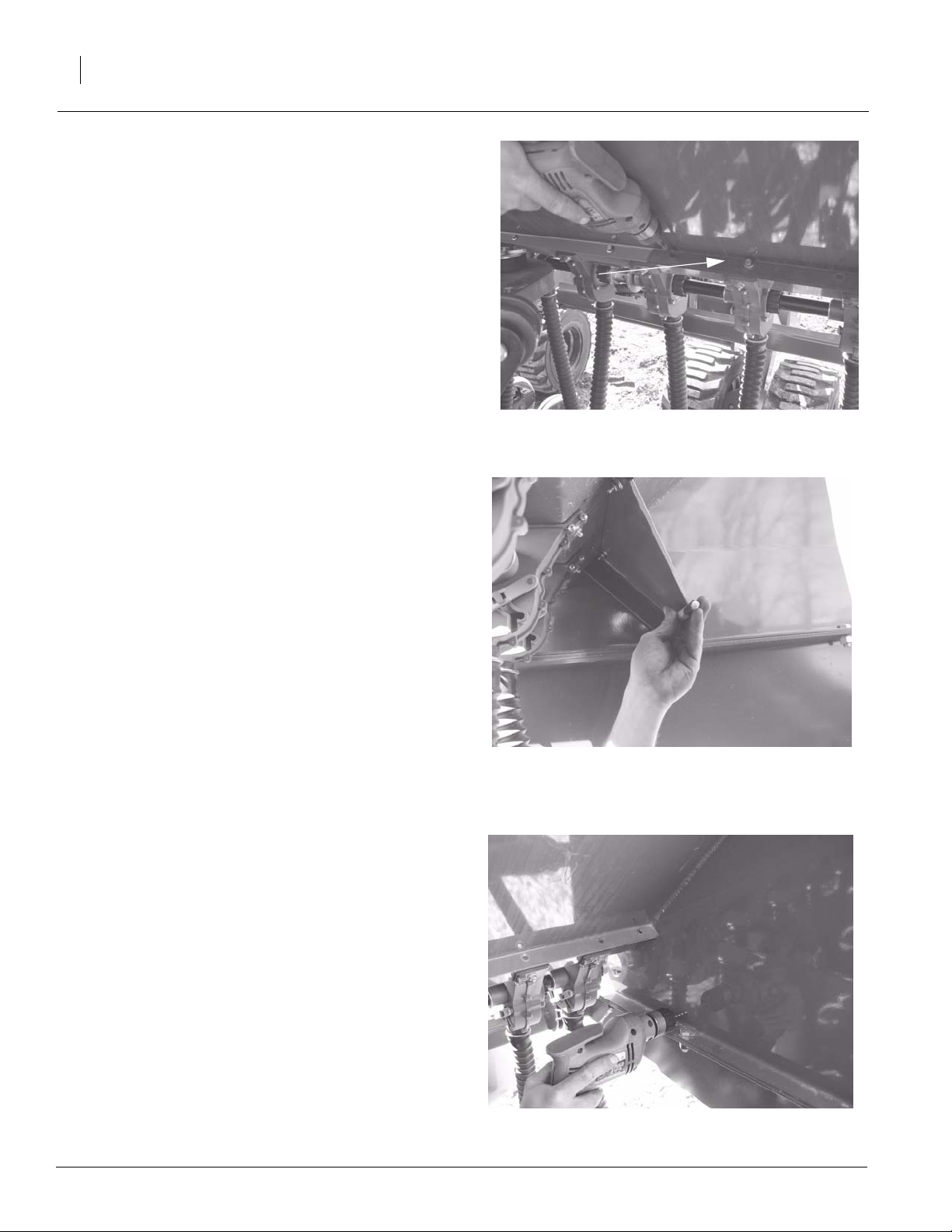
Refer to Figure 2
6. Repeat steps one through three on the front
side of box.
7. Remove template and install the two bolts
used to hold the template, in the two inside
holes, leaving three holes blank at the end of
the tray.
Great Plains Mfg., Inc.
Template
Refer to Figure 3
8. Install the gusset using the 1/4"x 1" boltsand
1/4" flange nuts on thebottom sideof thetray
flange and tighten. Using a transfer punch or
centerpunch,markthe 9/16"holelocationsin
the end panel.
Refer to Figure 4
9. Removea gusset anddrill apilotholethrough
the end panel.
22534
22535
Figure 2
Using template on Front Side
Figure 3
Using Transfer Punch
22536
197-008M 6/1/2004
Figure 4
Drilling Pilot Hole
Page 3

Great Plains Mfg., Inc.
Refer to Figure 5
10. Drill a 9/16" hole from the outside of the end
panel.
Refer to Figure 6
11. Reinstall the gusset using the 1/4" x 1" bolts
and 1/4" flange nuts and 1/2" x 1 1/4" bolts,
1/2" lock washers and 1/2" nuts. Repeatthis
process on each end of the trays.
22537
Installation Instructions
Figure 5
Drilling 9/16" Hole
3
Refer to Figure 7
12. Remove the box partition top nut (1) on front
side of box and install thepartition upperpad
(2). Reinstall the nut leaving loose. Level the
pad and tighten the nut.
6/1/2004
22538
Figure 6
Gusset
22543
Figure 7
Partition Upper Pad
197-008M
Page 4

Great Plains Mfg., Inc.
197-006A 3N-40 BOX SUPPORT UPDATE KIT
Qty. Part No. Part Description
6 118-052H BOX PARTITION UPPER PAD
1 197-008M 3N-40 BOX UPDATE MANUAL
3 197-197D 3N-40F BOX GUSSET LH
3 197-288D 3N-40F BOX GUSSET RH
1 197-296D HOLE TEMPLATE
12 802-083C HFSS 1/2-13X1 1/4 GR8
18 802-196C HFSS 1/4-20X5/8 GR5
18 802-375C HFSS 1/4-20X1 GR5
12 803-020C NUT HEX 1/2-13 PLT
36 803-088C NUT HEX LOCK 1/4-20 FLG
12 804-015C WASHER LOCK SPRING 1/2 PLT
Installation Instructions
4
197-007A 3N-40P BOX SUPPORT UPDATE KIT
Qty. Part No. Part Description
6 118-052H BOX PARTITION UPPER PAD
1 197-008M 3N-40 BOX UPDATE MANUAL
3 197-290D 3N-40P BOX GUSSET RH
3 197-289D 3N-40P BOX GUSSET LH
1 197-296D HOLE TEMPLATE
12 802-083C HFSS 1/2-13X1 1/4 GR8
18 802-196C HFSS 1/4-20X5/8 GR5
18 802-375C HFSS 1/4-20X1 GR5
12 803-020C NUT HEX 1/2-13 PLT
36 803-088C NUT HEX LOCK 1/4-20 FLG
12 804-015C WASHER LOCK SPRING 1/2 PLT
197-008M6/1/2004
 Loading...