

Page 1
Table of Contents Index
Operator Manual
3N-4010P, 3N-4010HDP, 3N-4020P and 3N-4025P
3-Section 40-Foot No-Till Precision Drills
Manufacturing, Inc.
www.greatplainsmfg.com
Read the operator manual entirely. When you see this symbol, the subsequent
instructions and warnings are serious - follow without exception. Your life and
!
the lives of others depend on it!
20293
Illustrations may show optional equipment not supplied with standard unit or may
depict similar models where a topic is identical.
ORIGINAL INSTRUCTIONS
© Copyright 2014 Printed 2014-01-29 196-538M
Table of Contents Index
EN
Page 2

3N-40P Table of Contents Index
196-538M Table of Contents Index 2014-01-29
Page 3

Great Plains Manufacturing, Inc. Cover Index iii
Table of Contents
Important Safety Information ...................................... 1
Safety Decals ................................................................. 6
Introduction ................................................................11
Document Family .........................................................11
Description of Unit ........................................................11
Models Covered by this Manual ...............................11
Intended Usage ........................................................12
Using This Manual........................................................12
Definitions................................................................. 12
Owner Assistance ........................................................12
Preparation and Setup ...............................................13
Pre-Setup Checklist......................................................13
Hitching ........................................................................13
Make Electrical Connections ....................................13
Make Hydraulic Connections.................................... 14
Hydraulic Circuit Connections ..................................14
Electrical Hookup .........................................................16
Initial Setup...................................................................17
Initial Tractor Setup ..................................................17
Veris Controller.....................................................17
Seed Monitor Console ..........................................18
Point Row Switch Module.....................................20
Drill Setup Checks....................................................20
Hydraulic Bleed ....................................................20
Drill Level..............................................................20
Drill Option Setup .....................................................20
Scrapers (Option) ................................................. 20
Marker Setup (Option) ..........................................21
Install Weight Brackets (Option)...............................21
Install Outer Brackets ........................................... 22
Install Mid-Wing Brackets .....................................23
Operating Instructions...............................................24
Pre-Start Checklist .......................................................24
Lift / Lower....................................................................25
Opener Operation Lowered......................................25
Rephasing Lift System..............................................25
Lift Cylinder Lock-Up ................................................26
Folding the Drill ............................................................26
Unfolding the Drill .........................................................28
Transport ......................................................................29
Pre-Transport Checklist............................................ 29
Typical Drill Weights.................................................30
Loading Seed ............................................................... 31
Seed Lubricants ...........................................................32
Planting ........................................................................33
Seed Rate ................................................................ 33
About Hydraulic Drive Rate.................................. 33
Seeding Depth ......................................................... 33
Point Row Switches ..................................................... 34
Point Row CAL Mode...............................................34
Field Operations........................................................... 35
Final Field Checklist ................................................. 35
Planting Sequence ................................................... 35
Marker Operation (Option) ........................................... 36
Parking......................................................................... 37
Storage ........................................................................ 37
Hydraulic Drive Operation......................................... 38
Drive Operational Requirements.................................. 38
Hydraulic System: .................................................... 38
Electrical System:..................................................... 38
Tractor Hookup ............................................................ 38
Hydraulics: ............................................................... 38
Electrical:.................................................................. 38
Controller Menu ........................................................... 39
Console Functions ....................................................... 40
Basic Operation ........................................................... 40
Power Up ................................................................. 40
Seed Rate ................................................................ 40
Power Off ................................................................. 40
Hydraulic Drive Field Operations ................................. 41
Seed Rate Calibration.................................................. 42
Seed Rate Calibration Steps....................................42
Prime Seed Meters .............................................. 46
Full Calibration .....................................................49
Speed Calibration ........................................................ 53
Varying Rates with Pre-set Function............................ 56
GPS-Based Planting .................................................... 57
FarmWorks SiteMate ............................................... 57
GP Precision Population Settings ............................ 58
Ag Leader PF3000 ................................................... 59
Precision Population Settings .............................. 60
Seeding Charts ............................................................ 61
Adjustments ............................................................... 71
Planting Depth ............................................................. 71
Frame Level ................................................................. 72
Frame Height ............................................................... 72
Frame Height without Frame-Mounted Coulters.......... 72
Frame-Mounted Coulters ............................................. 75
Frame Height - Frame Mounted Coulters ................ 75
© Copyright 2014 All rights Reserved
Great Plains Manufacturing, Inc. provides this publication “as is” without warranty of any kind, either expressed or implied. While every precaution has been
taken in the preparation of this manual, Great Plains Manufacturing, Inc. assumes no responsibility for errors or omissions. Neither is any liability assumed for
damages resulting from the use of the information contained herein. Great Plains Manufacturing, Inc. reserves the right to revise and improve its products as
it sees fit. This publication describes the state of this product at the time of its publication, and may not reflect the product in the future.
2014-01-29 Cover Index 196-538M
Trademarks of Great Plains Manufacturing, Inc. include: Singulator Plus, Swath Command, Terra-Tine.
Registered Trademarks of Great Plains Manufacturing, Inc. include:
Air-Pro, Clear-Shot, Discovator, Great Plains, Land Pride, MeterCone, Nutri-Pro, Seed-Lok, Solid Stand,
Terra-Guard, Turbo-Chisel, Turbo-Chopper, Turbo Max, Turbo-Till, Ultra-Till, Ver ti-Till, Whirlfilter, Yield-Pro.
Brand and Product Names that appear and are owned by others are trademarks of their respective owners.
Printed in the United States of America
Page 4

iv 3N-40P Table of Contents Index Great Plains Manufacturing, Inc.
Individual Frame-Mounted Coulter Depth ................ 77
Frame-Mounted Coulter Force................................. 78
Row Unit Shut-Off ........................................................ 79
Seed Meter Setup and Adjustment .......................... 79
10HD, 25 Series Meter Removal ......................... 79
Disengage Meter.................................................. 80
10HD, 25 Series Meter Wheel Replacement ....... 80
Meter Installation.................................................. 82
10HD, 25 Series Finger Meter Adjustments......... 82
Finger Meter Brush Adjustment ........................... 83
Finger Meter Inserts................................................. 84
Finger Meter Sprocket Indexing (Stagger)................... 85
Sprocket Indexing Charts......................................... 86
Indexing Fine Adjustment ........................................ 87
6-Finger Meter Stagger Adjustment ..................... 87
12-Finger Meter Stagger Adjustment ................... 88
10 and 20 Series Meter Wheel Replacement .......... 89
Unit-Mount Cleaner Adjustments ............................. 90
Implement Lift Switch Adjustment................................ 91
Frame Weight .............................................................. 93
Available Down Force .............................................. 93
Marker Adjustments ..................................................... 94
Marker Disk Adjustment........................................... 94
Adjusting Mark Width ........................................... 94
10P Series Row Unit Adjustments ............................... 95
10P Series Row Unit Down Pressure ...................... 96
10 Series Disk Blade Adjustments........................... 97
10 Series Seed Firmer Adjustments ........................ 98
10 Series Opener Depth .......................................... 99
10HD Series Row Unit Adjustments .......................... 100
Unit-Mounted Coulter Adjustments ........................ 101
10HD Row Unit Down Pressure............................. 103
Row Unit Down Pressure....................................... 104
10HDP Series Down-Pressure........................... 104
10HD Row Unit Lock-Up .................................... 105
10HD Disk Blade Adjustments............................... 105
10HD Seed Firmer Adjustments ............................ 106
10HD Press Wheel Adjustments............................ 107
20P Series Row-Unit Adjustments............................. 109
20P Series Row-Unit Down Pressure .................... 110
20P Series Row-Unit Planting Depth ..................... 110
20P Series Disk Blade Adjustments....................... 111
Side Gauge Wheel Adjustments ............................ 111
20P Series Seed Firmer Adjustments.................... 113
20P Series Press Wheel Adjustments ................... 114
25 Series Row-Unit Adjustments ............................... 115
25 Series Row Unit Down-Pressure....................... 116
Row Unit Shut Off .................................................. 118
25 Series Opener Depth ........................................ 119
25 Series Disk Blade Adjustments......................... 119
25 Series Side Gauge Wheel Scrapers ................. 120
25 Series Seed Firmer Adjustments .......................121
25 Series Seed-Lok® Lock-Up................................121
Seed-Lok® Seed Firmer Lock-Up (2010+)..........122
25 Series Press Wheel Adjustments ......................122
Troubleshooting .......................................................124
General Drill Troubleshooting.....................................124
Point Row Troubleshooting ........................................129
Hydraulic Drive Troubleshooting ................................130
Calibration Troubleshooting:...................................132
Hydraulic Drive Troubleshooting Flow Chart ..............133
Hydraulic Drive Electronics Troubleshooting..............134
GPS Troubleshooting .................................................135
Maintenance and Lubrication..................................137
Welding.......................................................................137
Cleaning Out Meters...................................................138
10 and 20 Series Meter Slide Maintenance................140
Frame Alignment and Level........................................142
Tongue Spacer Block .................................................144
Bleeding Hydraulics....................................................145
Bleeding Lift Hydraulics ..........................................145
Bleeding Fold Hydraulics ........................................146
Marker Maintenance...................................................147
Bleeding Markers....................................................147
Marker Speed .........................................................147
Marker Shear Bolt Replacement.............................148
Marker Chain Length ..............................................149
Electric Clutch Lockup ................................................149
Hydraulic Drive Maintenance......................................150
To change the element: ..........................................150
Row Unit Maintenance ...............................................151
Seed Flap Replacement (s/n 1054PP+) .................151
Seed Flap Replacement (s/n 1053PP-) ..................151
10HD Opener Maintenance ....................................152
20 Series Opener Maintenance ..............................152
Lubrication ..................................................................154
Options ......................................................................160
Appendix ...................................................................170
Specifications and Capacities.....................................170
3N-4010P Specifications and Capacities................170
3N-4010HDP Specifications and Capacities ..........171
3N-4020P Specifications and Capacities................172
3N-4025P Specifications and Capacities................173
Tire Inflation Chart ......................................................174
Torque Values Chart ..................................................175
Row Spacing Data......................................................176
Hydraulic Diagram ......................................................179
Sprocket Indexing Charts (Metric) ..............................180
Warranty .....................................................................181
Index ..........................................................................183
196-538M Table of Contents Index 2014-01-29
Page 5
Great Plains Manufacturing, Inc. Table of Contents Index 1
Important Safety Information
Look for Safety Symbol
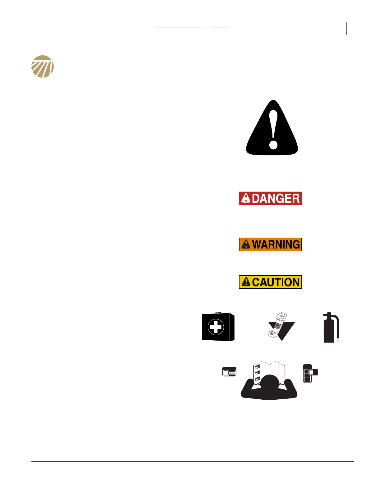
The SAFETY ALERT SYMBOL indicates there is a
potential hazard to personal safety involved and extra
safety precaution must be taken. When you see this
symbol, be alert and carefully read the message that
follows it. In addition to design and configuration of
equipment, hazard control and accident prevention are
dependent upon the awareness, concern, prudence and
proper training of personnel involved in the operation,
transport, maintenance and storage of equipment.
Be Aware of Signal Words
Signal words designate a degree or level of hazard
seriousness.
DANGER indicates an imminently hazardous situation
which, if not avoided, will result in death or serious injury.
This signal word is limited to the most extreme situations,
typically for machine components that, for functional
purposes, cannot be guarded.
WARNING indicates a potentially hazardous situation
which, if not avoided, could result in death or serious
injury, and includes hazards that are exposed when
guards are removed. It may also be used to alert against
unsafe practices.
CAUTION indicates a potentially hazardous situation
which, if not avoided, may result in minor or moderate
injury. It may also be used to alert against unsafe
practices.
Prepare for Emergencies
▲ Be prepared if a fire starts
▲ Keep a first aid kit and fire extinguisher handy.
▲ Keep emergency numbers for doctor, ambulance, hospital
and fire department near phone.
000
112
911
999
Be Familiar with Safety Decals
▲ Read and understand “Safety Decals” on page 6,
thoroughly.
▲ Read all instructions noted on the decals.
▲ Keep decals clean. Replace damaged, faded and illegible
decals.
2014-01-29 Table of Contents Index 196-538M
Page 6

2 3N-40P Table of Contents Index Great Plains Manufacturing, Inc.
Wear Protective Equipment
▲ Wear protective clothing and equipment.
▲ Wear clothing and equipment appropriate for the job. Avoid
loose-fitting clothing.
▲ Because prolonged exposure to loud noise can cause
hearing impairment or hearing loss, wear suitable hearing
protection such as earmuffs or earplugs.
▲ Because operating equipment safely requires your full
attention, avoid wearing entertainment headphones while
operating machinery.
Handle Chemicals Properly
Agricultural chemicals can be dangerous. Improper use
can seriously injure persons, animals, plants, soil and
property.
▲ Do not use liquid treatments with drill.
▲ Read and follow chemical manufacturer’s instructions.
▲ Wear protective clothing.
▲ Handle all chemicals with care.
▲ Avoid inhaling smoke from any type of chemical fire.
▲ Never drain, rinse or wash dispensers within 100 feet
(30 m) of a freshwater source, nor at a car wash.
▲ Store or dispose of unused chemicals as specified by
chemical manufacturer.
▲ Dispose of empty chemical containers properly. Laws
generally require power rinsing or rinsing three times,
followed by perforation of the container to prevent re-use.
Avoid High Pressure Fluids
Escaping fluid under pressure can penetrate the skin,
causing serious injury.
▲ Avoid the hazard by relieving pressure before disconnecting
hydraulic lines.
▲ Use a piece of paper or cardboard, NOT BODY PARTS, to
check for suspected leaks.
▲ Wear protective gloves and safety glasses or goggles when
working with hydraulic systems.
▲ If an accident occurs, seek immediate medical attention
from a physician familiar with this type of injury.
196-538M Table of Contents Index 2014-01-29
Page 7
Great Plains Manufacturing, Inc. Table of Contents Index Important Safety Information 3
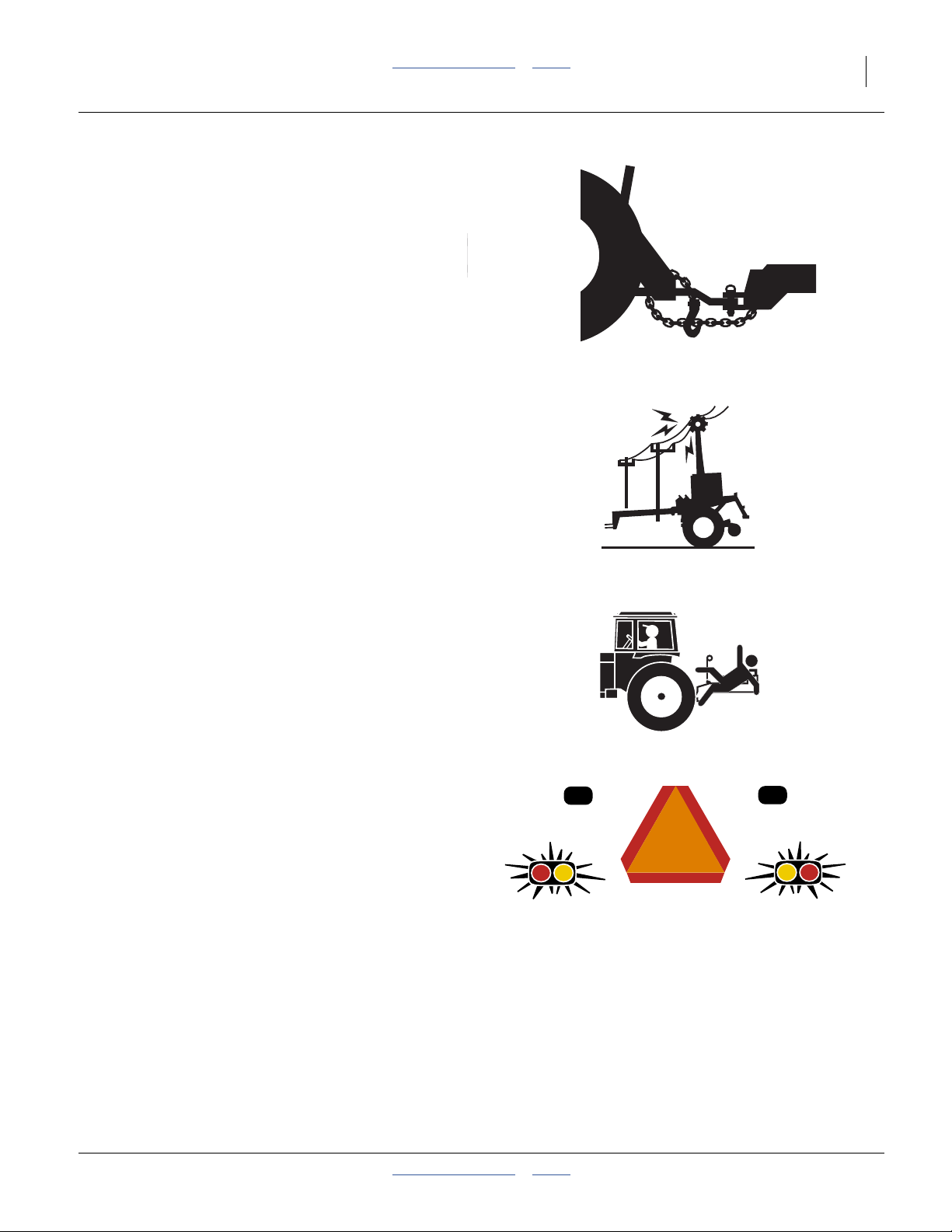
Use A Safety Chain
▲ Use a safety chain to help control drawn machinery should
it separate from tractor drawbar.
▲ Use a chain with a strength rating equal to or greater than
the gross weight of towed machinery.
▲ Attach chain to tractor drawbar support or other specified
anchor location. Allow only enough slack in chain to permit
turning.
▲ Replace chain if any links or end fittings are broken,
stretched or damaged.
▲ Do not use safety chain for towing.
Check for Overhead Lines
Drill markers contacting overhead electrical lines can
introduce lethal voltage levels on drill and tractor frames.
A person touching almost any metal part can complete
the circuit to ground, resulting in serious injury or death.
At higher voltages, electrocution can occur without direct
contact.
▲ Avoid overhead lines during seed loading and marker
operations.
Keep Riders Off Machinery
Riders obstruct the operator’s view. Riders could be
struck by foreign objects or thrown from the machine.
▲ Never allow children to operate equipment.
▲ Keep all bystanders away from machine when
folding/unfolding, raising/lowering markers,
raising/lowering openers, and transporting.
Use Safety Lights and Devices
Slow-moving tractors and towed implements can create
a hazard when driven on public roads. They are difficult
to see, especially at night.
▲ Use flashing warning lights and turn signals whenever
driving on public roads.
▲ Use lights and devices provided with drill.
2014-01-29 Table of Contents Index 196-538M
Page 8
4 3N-40P Table of Contents Index Great Plains Manufacturing, Inc.
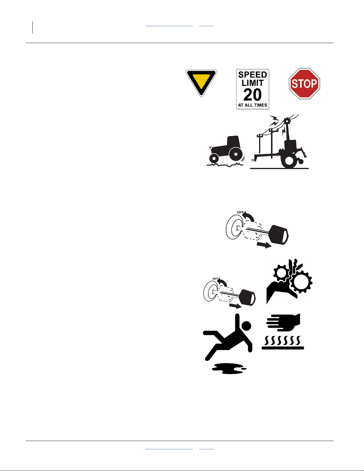
Transport Machinery Safely
Maximum transport speed for drill is 20 mph (32 kph).
Some rough terrains require a slower speed. Sudden
braking can cause a towed load to swerve and upset.
▲ Drill must be raised, locked-up, folded and locked for
transport.
▲ Do not exceed 20 mph (32 kph). Never travel at a speed
which does not allow adequate control of steering and
stopping. Reduce speed if towed load is not equipped with
brakes.
▲ Comply with national, regional and local laws.
▲ Do not tow a load that weighs more than 1.5x the weight of
the tractor. See page 29 for details.
▲ Carry reflectors or flags to mark drill in case of breakdown
on the road.
▲ Keep clear of overhead power lines and other obstructions
when transporting. Refer to transport dimensions under
“Specifications and Capacities” on page 170.
Shutdown and Storage
▲ Clean out and safely store or dispose of residual chemicals.
▲ Secure drill using blocks and transport locks. Lower
openers if not locked up.
▲ Store in an area where children normally do not play.
Practice Safe Maintenance
▲ Understand procedure before doing work. Use proper tools
and equipment. Refer to this manual on the Parts manual
for additional information.
▲ Work in a clean, dry area.
▲ Put tractor in park, turn off engine, and remove key before
performing maintenance.
▲ Make sure all moving parts have stopped and all system
pressure is relieved.
▲ Disconnect battery ground cable (-) before servicing or
adjusting electrical systems or before welding on drill.
▲ Inspect all parts. Make sure parts are in good condition and
installed properly.
▲ Remove buildup of grease, oil or debris.
▲ Remove all tools and unused parts from drill before
operation.
196-538M Table of Contents Index 2014-01-29
Page 9

Great Plains Manufacturing, Inc. Table of Contents Index Important Safety Information 5
Tire Safety
Tire changing can be dangerous and should be
performed by trained personnel using correct tools and
equipment.
▲ When inflating tires, use a clip-on chuck and extension hose
long enough for you to stand to one side–not in front of or
over tire assembly. Use a safety cage if available.
▲ When removing and installing wheels, use wheel-handling
equipment adequate for weight involved.
Safety At All Times
Thoroughly read and understand the instructions in this
manual before operation. Read all instructions noted on
the safety decals.
▲ Be familiar with all drill functions.
▲ Operate machinery from the driver’s seat only.
▲ Do not leave drill unattended with tractor engine running.
▲ Do not dismount a moving tractor. Dismounting a moving
tractor could cause serious injury or death.
▲ Do not stand between the tractor and drill during hitching.
▲ Keep hands, feet and clothing away from power-driven
parts.
▲ Wear snug-fitting clothing to avoid entanglement with
moving parts.
2014-01-29 Table of Contents Index 196-538M
Page 10
6 3N-40P Table of Contents Index Great Plains Manufacturing, Inc.
Safety Decals
Safety Reflectors and Decals
Your drill comes equipped with all lights, safety reflectors
and decals in place. They were designed to help you
safely operate your drill.
▲ Read and follow decal directions.
▲ Keep lights in operating condition.
▲ Keep all safety decals clean and legible.
▲ Replace all damaged or missing decals. Order new decals
from your Great Plains dealer. Refer to this section for
proper decal placement.
▲ When ordering new parts or components, also request
corresponding safety decals.
818-055C
To install new decals:
1. Clean the area on which the decal is to be placed.
2. Peel backing from decal. Press firmly on surface,
being careful not to cause air bubbles under decal.
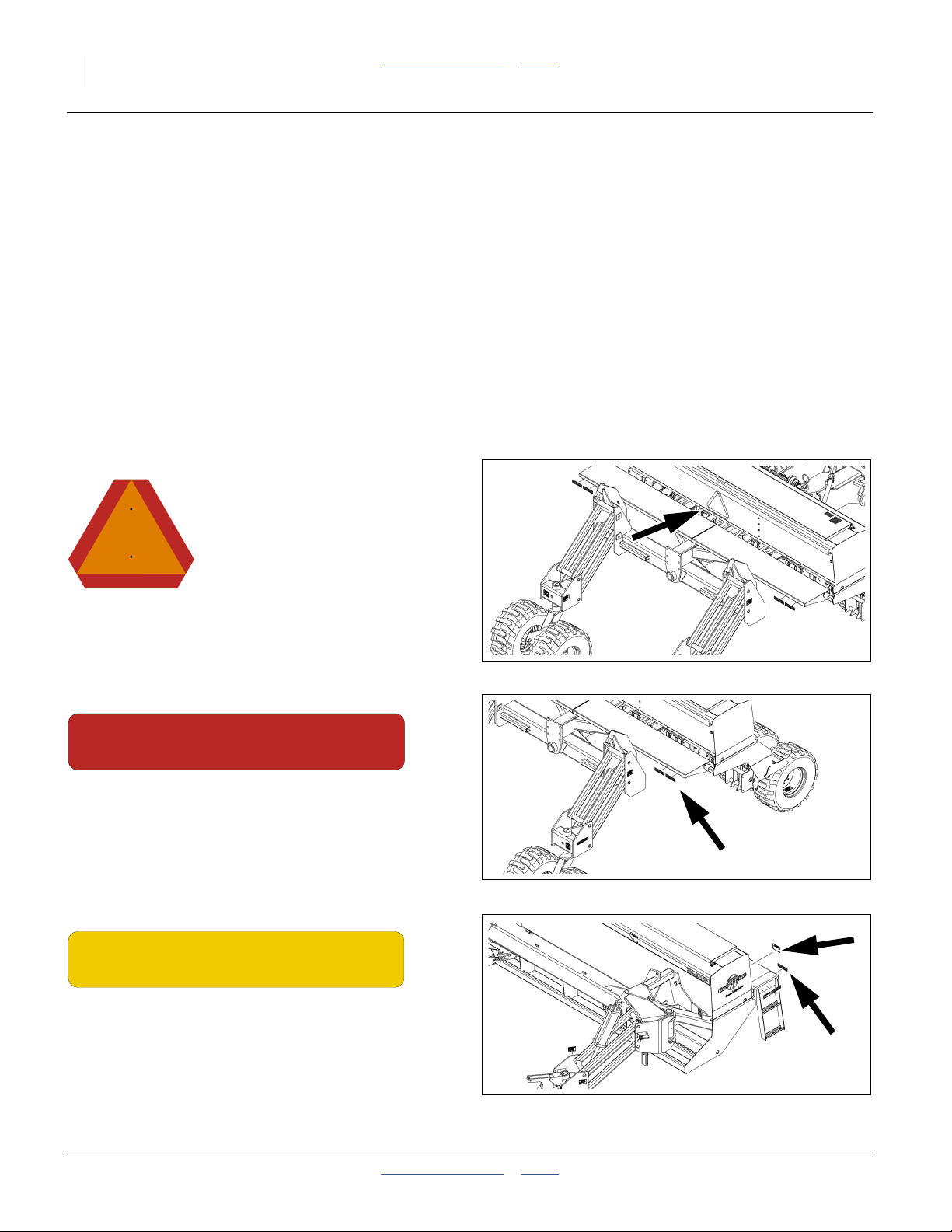
Slow Moving Vehicle Reflector
Center rear of center box;
1 total
838-266C
Red Reflectors
On the outside edge of center walkboard each end;
4 total
838-265C
Amber Reflectors
On the ends and back edges of walkboards on both
wings;
2 total
21791
21791
21791
196-538M Table of Contents Index 2014-01-29
Page 11
Great Plains Manufacturing, Inc. Table of Contents Index Important Safety Information 7
838-267C
Daytime Reflectors
On the outside edge of center walkboard each end;
2 total
21791
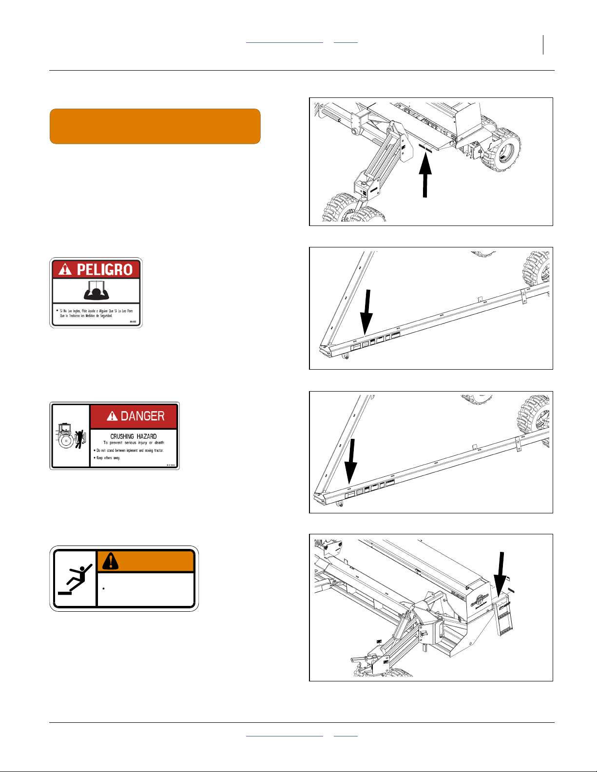
818-557C
Danger: Cannot Read English
On tongue near hitch;
1 total
818-590C
Danger: Crushing Hazard
On tongue near hitch;
1 total
838-102C
WARNING
To avoid serious injury or death:
Watch your step when climbing ladder or
walking on walkboard.
838-102C
21791
21791
Danger: Falling Hazard
Outside edge of wing walkboards;
2 total
21791
2014-01-29 Table of Contents Index 196-538M
Page 12

8 3N-40P Table of Contents Index Great Plains Manufacturing, Inc.
818-045C
Warning: Pinch/Crush
On transport wheel assembly;
4 total
818-188C
WARNING
EXCESSIVE SPEED HAZARD
To Prevent Serious Injury or Death:
Do Not exceed 20 mph maximum transport
speed. Loss of vehicle control and/or machine
can result.
818-188C Rev. C
21791
21791
Warning: Speed Hazard
On tongue near hitch;
1 total
21791
818-339C
Warning: High Pressure Fluid Hazard
On tongue near hitch;
1 total
196-538M Table of Contents Index 2014-01-29
21791
Page 13
Great Plains Manufacturing, Inc. Table of Contents Index Important Safety Information 9
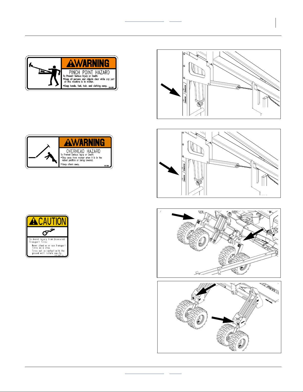
818-579C (Option)
Warning: Pinch Point
On marker, two with single, four with dual marker option;
2 or 4 total
20306
818-580C (Option)
Warning: Overhead Hazard
On marker, two with single, four with dual marker option;
2 or 4 total
818-398C
Caution: Tires Not A Step
Above all sets of tires;
6 total
20306
21791
21791
2014-01-29 Table of Contents Index 196-538M
Page 14
10 3N-40P Table of Contents Index Great Plains Manufacturing, Inc.
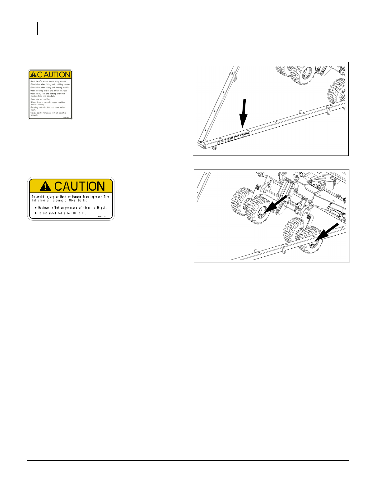
818-587C
Caution: General
On tongue near hitch;
1 total
21791
838-426C
Caution: Pressure/Torque
On the rim of each tire;
12 total
21791
196-538M Table of Contents Index 2014-01-29
Page 15
Great Plains Manufacturing, Inc. Table of Contents Index 11
Introduction
Great Plains welcomes you to its growing family of new
product owners. Your 3-Section 40-Foot No-Till Precision
Drill has been designed with care and built by skilled
workers using quality materials. Proper setup,
maintenance, and safe operating practices will help you
get years of satisfactory use.
Document Family
196-538M Operator Manuala (this manual)
196-286P Parts Manual
11001-1359-200605 Seed Monitor Manual
R
Description of Unit
The 3N-4010P, 3N-4010HDP, 3N-4020P and 3N-4025P
are pull-type singulated seeding implements outfitted
with hydraulic drive metering and seed monitor for use in
no-till or minimum-till conditions. Features:
3N-4010P 10 Series, parallel-arm openers.
3N-4010HDP 10HD (Heavy Duty) openers.
3N-4020P 20 Series side-depth-control openers
3N-4025P 25 Series side-depth-control openers
All models fold for transport.
Models Covered by this Manual
10 Series Openers:
3N-4010P-3115 31 Rows, 15 in/38 cm
3N-4010P-32TR 32 Rows/16 Twin, 30in/76 cm pairs
3N-4010P-32TRF 32 Rows/16 Twin, 30in/76 cm pairs
fertilizer coulters
3N-4010P-4810 48 Rows, 10 inch/25 cm
3N-4010P-6475 64 Rows, 7.5in/19 cm
10HD (Heavy Duty) Series Openers:
3N-4010HDP-32F 32 Rows, 15 in/38 cm
fertilizer coulters
3N-4010HDP-32TR 32 Rows/16 Twin, 30in/76 cm pairs
3N-4010HDP-3315 33 Rows, 15 inch/38 cm
3N-4010HDP-4810 48 Rows, 10 inch/25 cm
3N-4010HDP-49TS 49 Rows/16 Twin, 30 in/76 cm pairs
3N4010HDP-6475 64 Rows, 7.5 inch/19 cm
L
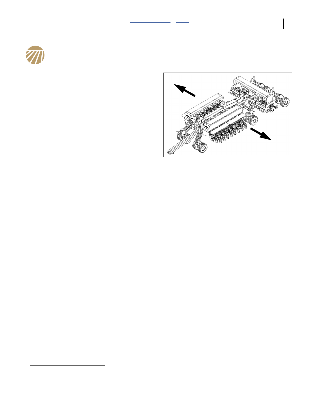
Figure 1
Left/Right Notation
20 Series Openers:
3N-4020P-3115 31 Rows, 15 inch/38 cm
3N-4020P-32TR 32 Rows/16 Twin, 30 in/76 cm pairs
3N-4020P-32TRF 32 Rows/16 Twin, 30 in/76 cm pairs
fertilizer coulters
3N-4020P-4810 48 Rows, 10 inch/25 cm
3N-4020P-6475 64 Rows, 7.5 inch/19 cm
25 Series Openers:
3N-4025P-3315 33 Rows, 15 inch/38 cm
3N-4025P-32TR 32 Rows/16 Twin, 30 in/76 cm pairs
3N-4025P-49TRS 49 Rows/16 Twin, 30 in/76 cm pairs
Previous 3N-40P models are covered in manual part
number 196-286 m.
20293
a. This manual also covers seeding rate. There is no separate Seed Rate manual.
2014-01-29 Table of Contents Index 196-538M
Page 16

12 3N-40P Table of Contents Index Great Plains Manufacturing, Inc.
Intended Usage
Use the drill to seed production-agriculture crops only.
Do not modify the drill for use with attachments other
than Great Plains options and accessories specified or
recommended for use with the drill.
Using This Manual
This manual will familiarize you with safety, assembly,
operation, adjustments, troubleshooting, and
maintenance. Read this manual and follow the
recommendations to help ensure safe and efficient
operation.
The information in this manual is current at printing.
Some parts may change to assure top performance.
Definitions
The following terms are used throughout this manual.
Right-hand and left-hand as used in this manual are
determined by facing the direction the machine will travel
while in use unless otherwise stated.
Paragraphs in this format present a crucial point of information
related to the current topic.
Read and follow the directions to:
- remain safe,
- avoid serious damage to equipment and
- ensure desired field results.
Note: Paragraphs in this format provide useful
information related to the current topic.
Figure 2
Serial Number Plate
Model Number:__________________________
Serial Number: __________________________
Your Great Plains dealer wants you to be satisfied with
your new machine. If you do not understand any part of
this manual or are not satisfied with the service received,
please take the following actions.
1. Discuss the matter with your dealership service
manager. Make sure they are aware of any problems
so they can assist you.
2. If you are still unsatisfied, seek out the owner or
general manager of the dealership.
For further assistance write to:
20270
Owner Assistance
If you need customer service or repair parts, contact a
Great Plains dealer. They have trained personnel, repair
parts and equipment specially designed for Great Plains
products.
Refer to Figure 2
Your machine’s parts were specially designed and
should only be replaced with Great Plains parts. Always
use the serial and model number when ordering parts
from your Great Plains dealer. The serial number plate is
located on the front of the left hand side of the center
section.
Record your drill model and serial number here for quick
reference:
196-538M Table of Contents Index 2014-01-29
Product Support
Great Plains Mfg. Inc., Service Department
PO Box 5060
Salina, KS 67402-5060
785-823-3276
Page 17
Great Plains Manufacturing, Inc. Table of Contents Index 13
Preparation and Setup
This section will help you prepare your tractor and drill for
use. Before using the drill in the field, you must hitch the
drill to a suitable tractor and level the drill.
Pre-Setup Checklist
1. Read and understand “Important Safety
Information” on page 1.
2. Check that all working parts are moving freely, bolts
are tight, and cotter pins are spread.
3. Check that all grease fittings are in place and
lubricated. See “Lubrication” on page 154.
4. Check that all safety decals and reflectors are
correctly located and legible. Replace if damaged.
See “Safety Decals” on page 6.
5. Inflate tires to pressure recommended and tighten
wheel bolts as specified. “Appendix” on page 170.
Hitching
There are three hitch options (see page 160). Check that
the tractor and drill are compatible before hitching.
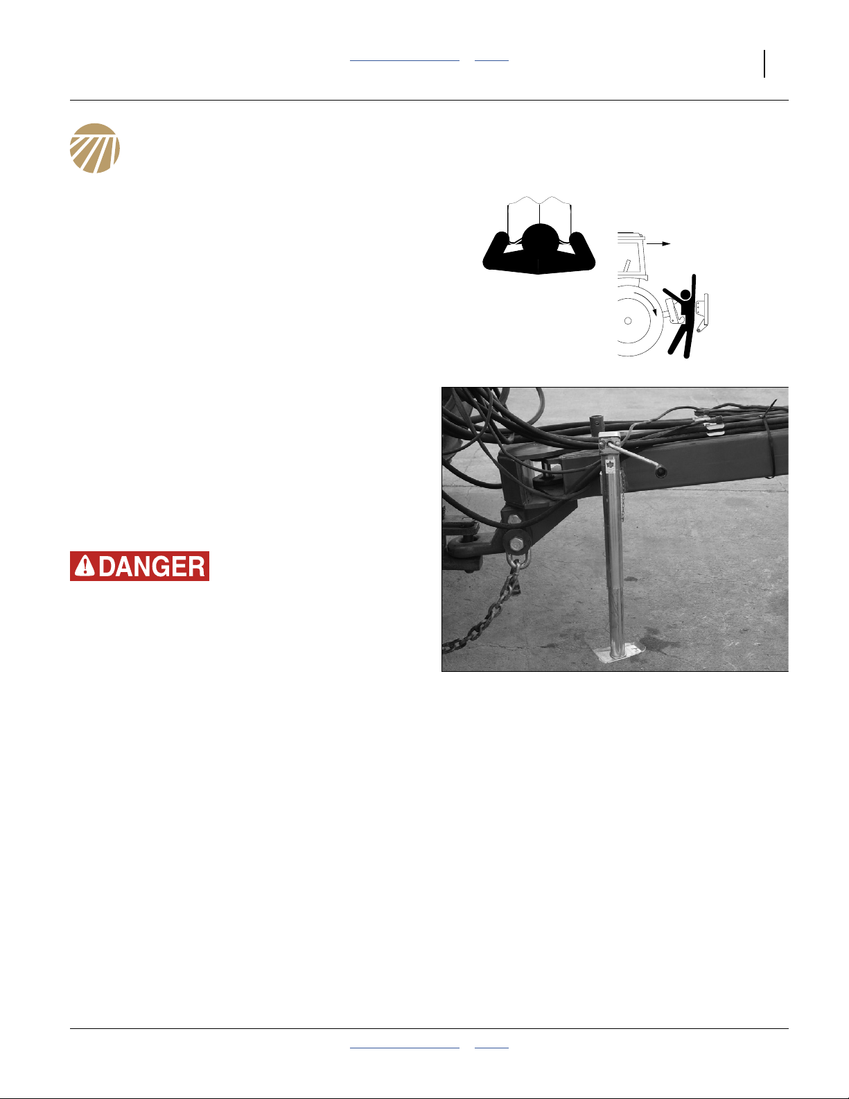
Crushing Hazard:
You may be severely injured or killed by being crushed
between the tractor and drill. Do not stand or place any part of
your body between machines being hitched. Stop tractor
engine and set park brake before installing hitch pins.
Refer to Figure 3
1. Use drill parking jack to raise or lower tongue as
needed. Hitch drill to tractor using a hitch pin of
adequate strength - minimum diameter 11⁄2inch
(38 mm).
2. Install a retaining clip on the hitch pin to prevent it
from working up.
3. Use jack to lower drill hitch onto tractor drawbar.
4. Securely attach drill safety chain to tractor drawbar.
5. Remove jack and store on stob at top of tongue.
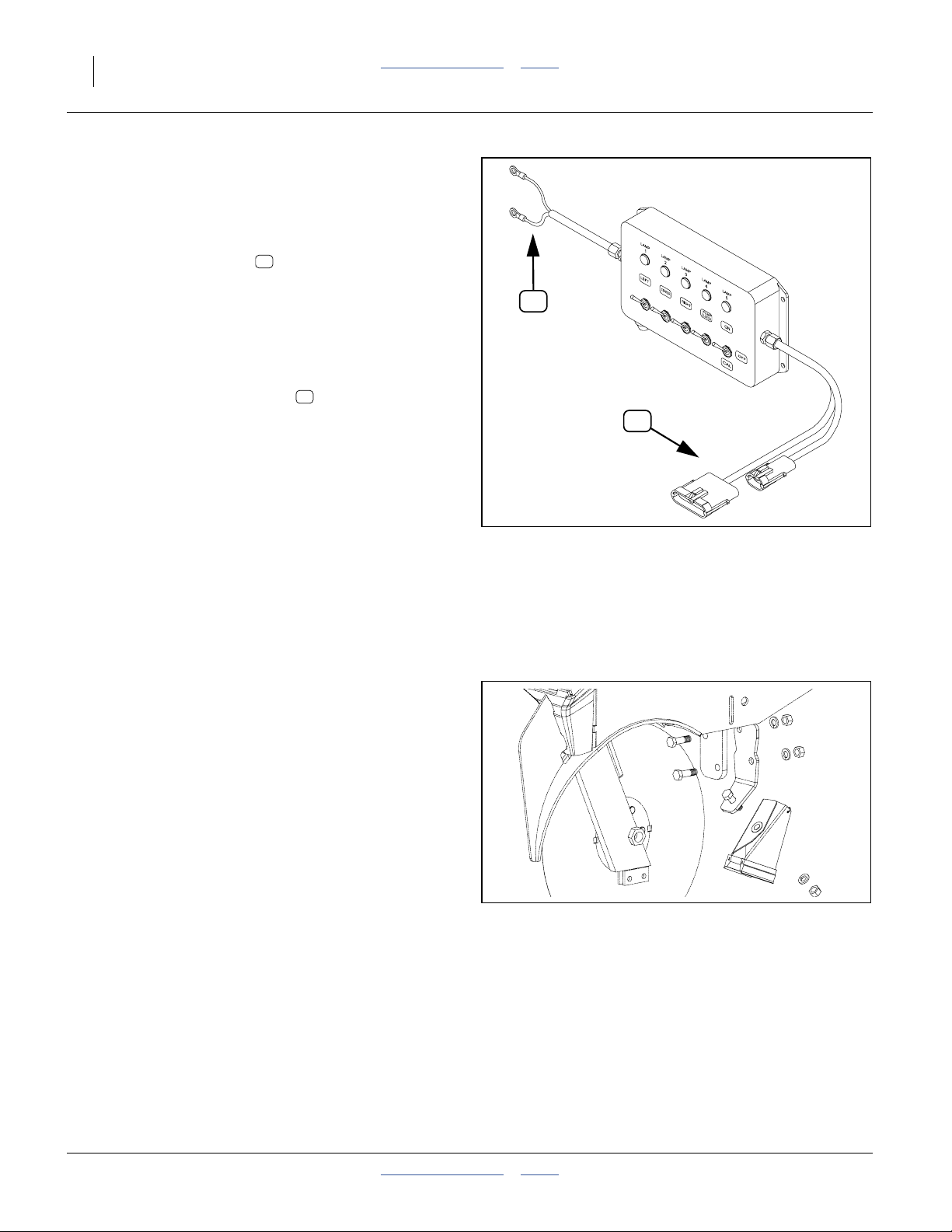
Make Electrical Connections
Make sure tractor is shut down with accessory power off
before making connections. Connections include:
Figure 3
Hitching Tractor to Drill
6. Lighting
7. Veris controller harness (see page 17 for console
installation)
8. Seed Monitor harness (see page 18 for console
installation)
9. Electric Clutch (Point Row) harness (2 connectors)
(see page 20 for switchbox installation)
20273
2014-01-29 Table of Contents Index 196-538M
Page 18
14 3N-40P Table of Contents Index Great Plains Manufacturing, Inc.
Make Hydraulic Connections
High Pressure Fluid Hazard:
Only trained personnel should work on system hydraulics!
Escaping fluid under pressure can penetrate skin, causing
serious injury. Avoid the hazard by relieving pressure before
disconnecting hydraulic lines. Use a piece of paper or
cardboard, NOT BODY PARTS, to check for leaks. Wear
protective gloves and safety glasses or goggles when working
with hydraulic systems. If an accident occurs, seek immediate
The drive is compatible only with closed center, PC (pressure
compensated) closed or LS (load sensing) hydraulic systems.
Do not use an open center system.
medical attention from a physician familiar with this type of
injury.
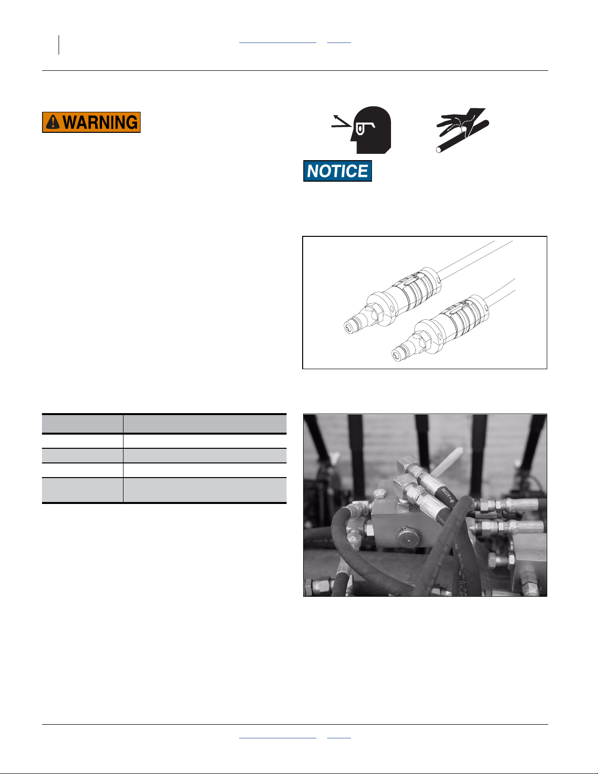
Refer to Figure 4
Great Plains hydraulic hoses have color coded handle
grips to help you hookup hoses to your tractor outlets.
Hoses that go to the same remote valve are marked with
the same color.
Hydraulic Circuit Connections
The drill has three or four hydraulic circuits. The standard
circuits power drive/locks, lift, and fold. If markers are
present, they require a fourth circuit (or an additional
selector valve sharing the fold circuit).
If the tractor has only one circuit rated for continuous
flow, reserve it for the hydraulic drive.
Current Style Color Coded Hose Handle Grips
Figure 4
Color Coded Hose Grips
31733
Hose Color Hydraulic Function
Gray Fold
Blue Lift
Green Marker Cylinders (Option)
Yellow
To distinguish hoses on the same hydraulic circuit, refer
to the symbol molded into the handle grip. Hoses with an
extended-cylinder symbol feed cylinder base ends.
Hoses with a retracted-cylinder symbol feed cylinder rod
ends.
10. Shut down tractor hydraulics.
11. Connect the hydraulic drive circuit.
12. Connect remaining circuits.
13. Check hose routing to ensure adequate slack for link
arm movement, and clearance from pinching or
abrading drill components.
Refer to Figure 5
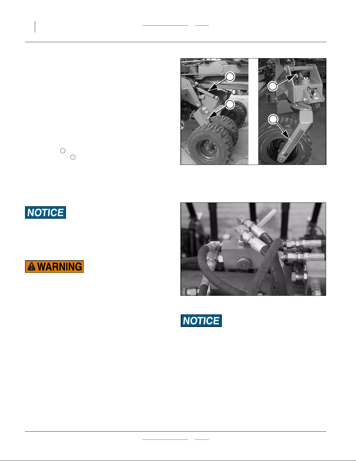
14. If the drill is to be unfolded, set the selector valve to
Locks (handle to drill center). Valve is located near
rear end of left tongue tube.
Hydraulic Drive and
Wing and Swivel Locks
Figure 5
Hitching: Drive/Lock Selector Valve
21844
196-538M Table of Contents Index 2014-01-29
Page 19
Great Plains Manufacturing, Inc. Table of Contents Index Preparation and Setup 15
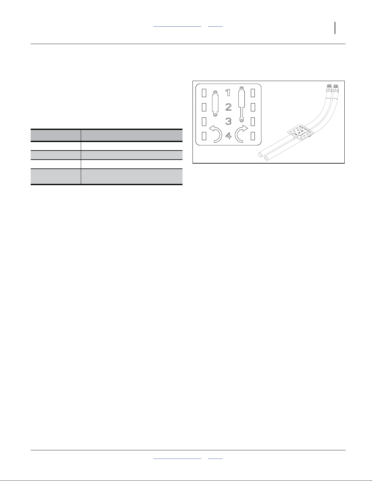
Older Style Hoses with Color Ties
Refer to Figure 6
Hoses that go to the same remote valve are marked with
the same color tie.
To distinguish hoses on the same hydraulic circuit, refer
to plastic hose label. The hose under an
extended-cylinder symbol feeds a cylinder base end. The
hose under a retracted-cylinder symbol feeds a cylinder
rod end.
Hose Color Hydraulic Function
White Fold
Blue Lift
Orange Marker Cylinders (Option)
Yellow
Hydraulic Drive and
Wing and Swivel Locks
Figure 6
Older Style Hoses with Label
817-348c
17641
2014-01-29 Table of Contents Index 196-538M
Page 20
16 3N-40P Table of Contents Index Great Plains Manufacturing, Inc.
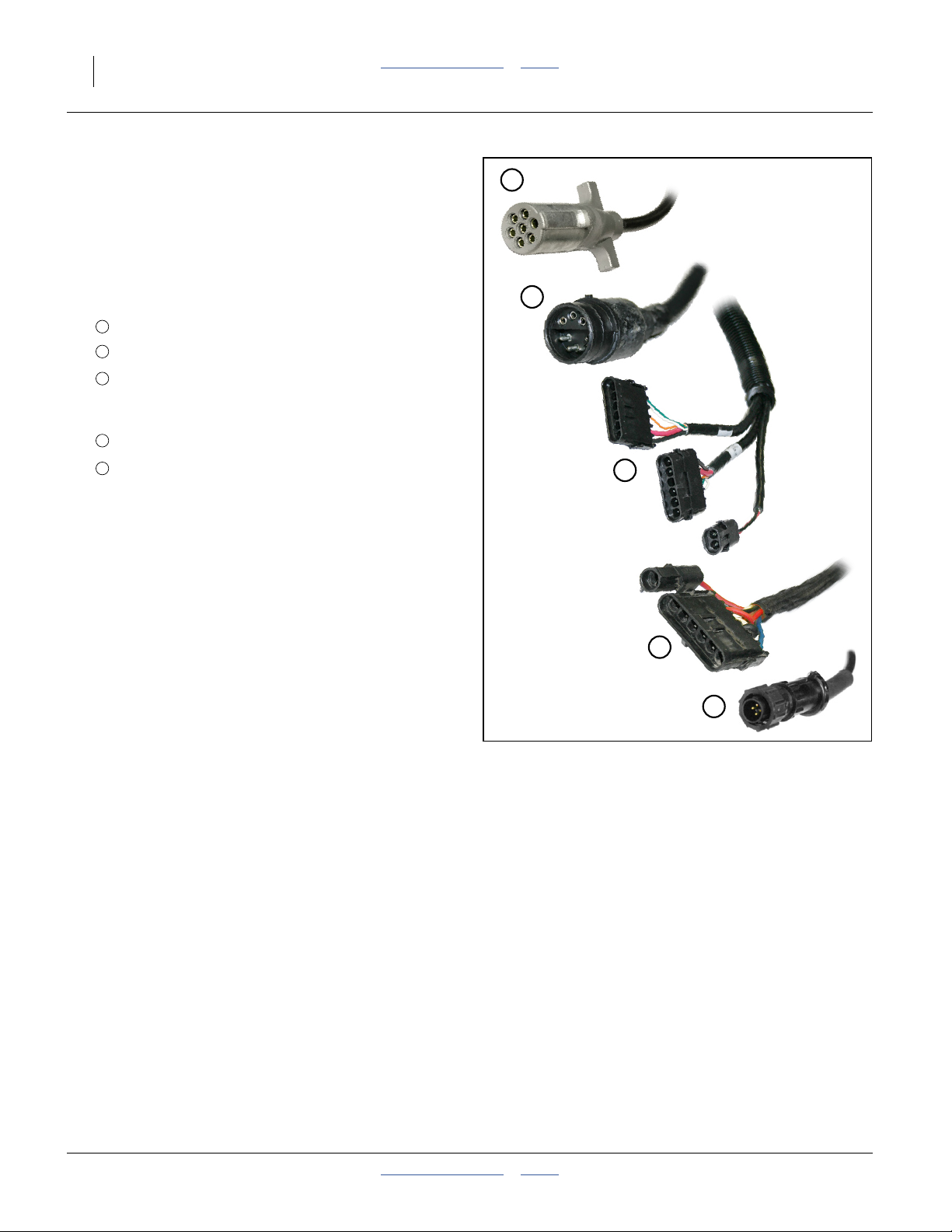
Electrical Hookup
Plug drill electrical lead into tractor seven-pin connector.
If your tractor is not equipped with an ASAE J560b
seven-pin connector, contact your dealer for installation.
Plug in any optional connectors or aftermarket
connectors, such as an drill-mounted GPS receiver. For
future reference, note any optional connectors on this
checklist.
1
❑ Lighting connector
2
❑ Veris hydraulic drive controller connectors
3
❑ Seed Manager SE connectors
Note: lower row counts may have only one connector
on the implement.
4
❑ Point Row switch module connector
5
❑ Speed connector
❑ __________________________
1
2
3
4
5
Figure 7
Electrical Connections
36051
36110
36120
36125
34715
196-538M Table of Contents Index 2014-01-29
Page 21
Great Plains Manufacturing, Inc. Table of Contents Index Preparation and Setup 17
Initial Setup
The following items need to be done for first use, and
some need to be re-done if the tractor changes.
Initial Tractor Setup
Three modules are mounted in the tractor cab. Route
harnesses clear of moving parts, and allow enough slack
for turns, especially on articulated tractors.
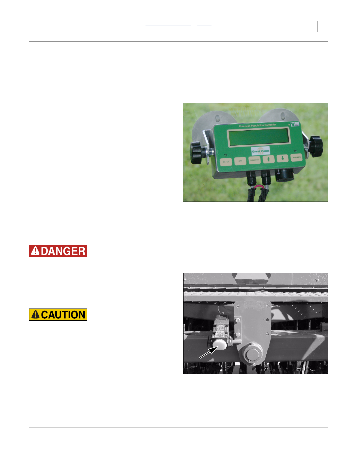
Veris Controller
The standard Veris hydraulic drive, controller module and
DICKEY-john radar are factory-installed on the drill. The
Veris console needs to be installed in the tractor prior to
first use. It includes suction cup feet that can support the
console on glazing for extended periods.
Refer to Figure 8
Mount the console where the display is visible during
planting, but does not obstruct vision of tractor or drill
systems, and does not impair safe highway transport.
Installation instructions are found in an included Veris
manual. Additional copies are available at:
www.veristech.com
Expanded operating information from that manual is
found in this manual, starting on page 38.
Once the console is installed, you can enter the initial
setup data by stepping through the calibration sequence
but not actually operating the motor. See page 42.
Figure 8
Veris Controller Console
28326
Moving Chain Hazard
Pinch/Crush Hazard
Shaft Entanglement Hazard
Be careful when working around drill while tractor is running.
Any movement detected by the radar gun (Figure 9) can
activate the Veris hydraulic drive causing motion of chains,
sprockets, shafts and seed meters.
Vision Hazard:
The DICKEY-john RVS II radar speed sensor is an intentional
radiator of RF energy. Although its radiated energy level is far
below the limits set by EN 61010-1: 1993\A2: 1995 - Chapter
12.4, it is advisable not to look directly into the face of the unit.
The radar must radiate toward the ground and at least 20 cm
(8 inches) away from a human during use to comply with the
RF human exposure limits per FCC 47 CFR Sec. 2.1091.
DO NOT mount or use the radar in a manner inconsistent with
its defined use.
Figure 9
DICKEY-john Radar
20310
2014-01-29 Table of Contents Index 196-538M
Page 22
18 3N-40P Table of Contents Index Great Plains Manufacturing, Inc.
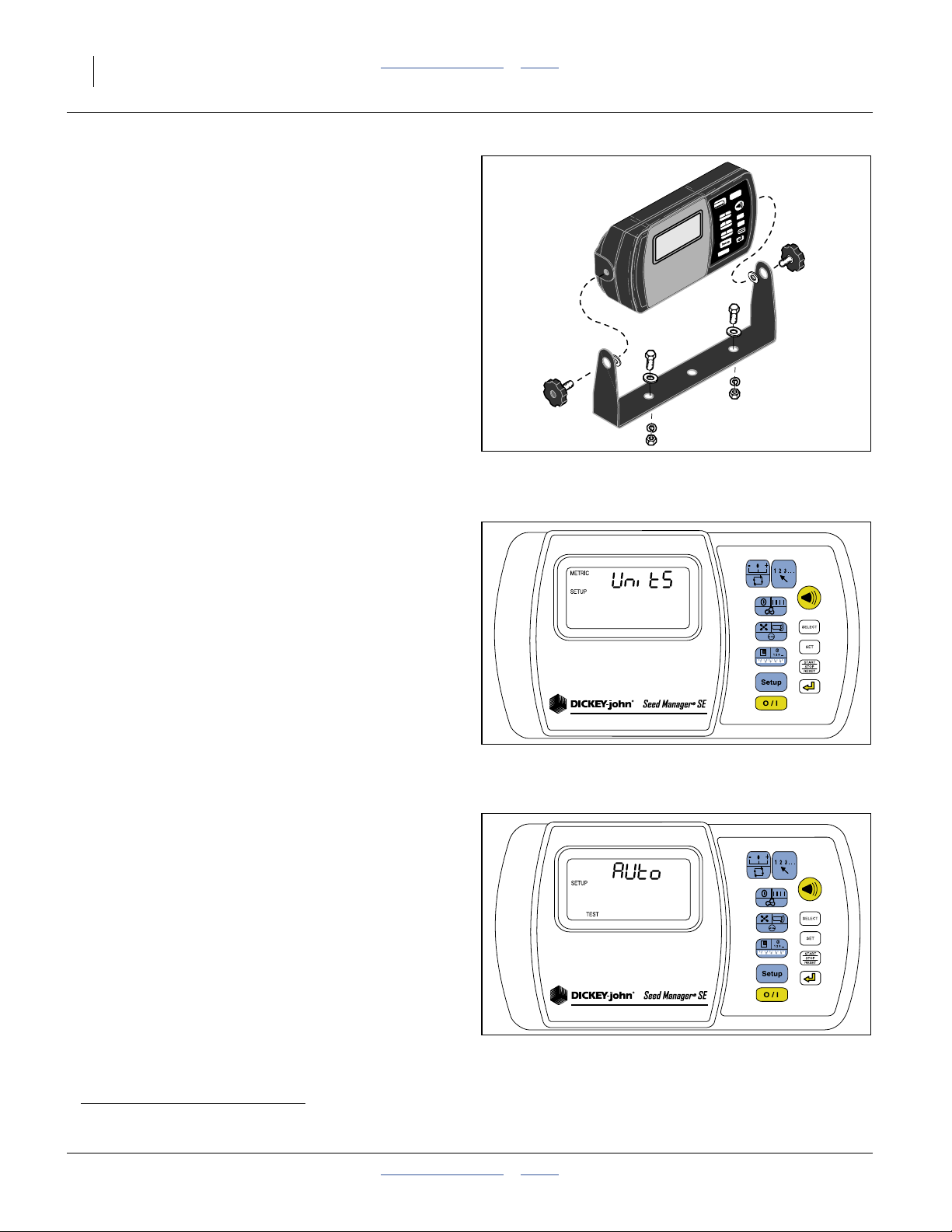
Seed Monitor Console
Refer to Figure 10
Consult the installation instructions included with the
console, and mount it in a convenient location.
If the cab is particularly noisy, or the operator customarily
wears a noise-cancelling headset, the alarms may not be
audible. Mount the module where the controls and status
indicators are visible during planting operations.
To use the speed and area functions of the seed monitor,
it needs to be connected to a speed sensor. Although the
drill includes a radar sensor, it is connected to the
hydraulic drive system, and does not include Y-cable to
share it with the seed monitor. Great Plains recommends
connecting the seed monitor to a separate speed sensor,
usually tractor-mounted.
Seed Monitor Setup
See the separate DICKEY-john manual for full details
initial setup of the seed monitor. The following
Figure 10
Seed Monitor Cab Module
27390
information may be useful in that process.
Have the drill hitched to the tractor, and all harnesses
connected. Although the monitor console can be
operated with the drill disconnected, the Auto
configuration cannot be run. The parameter numbers are
based on the Setup table in the DICKEY-john manual.
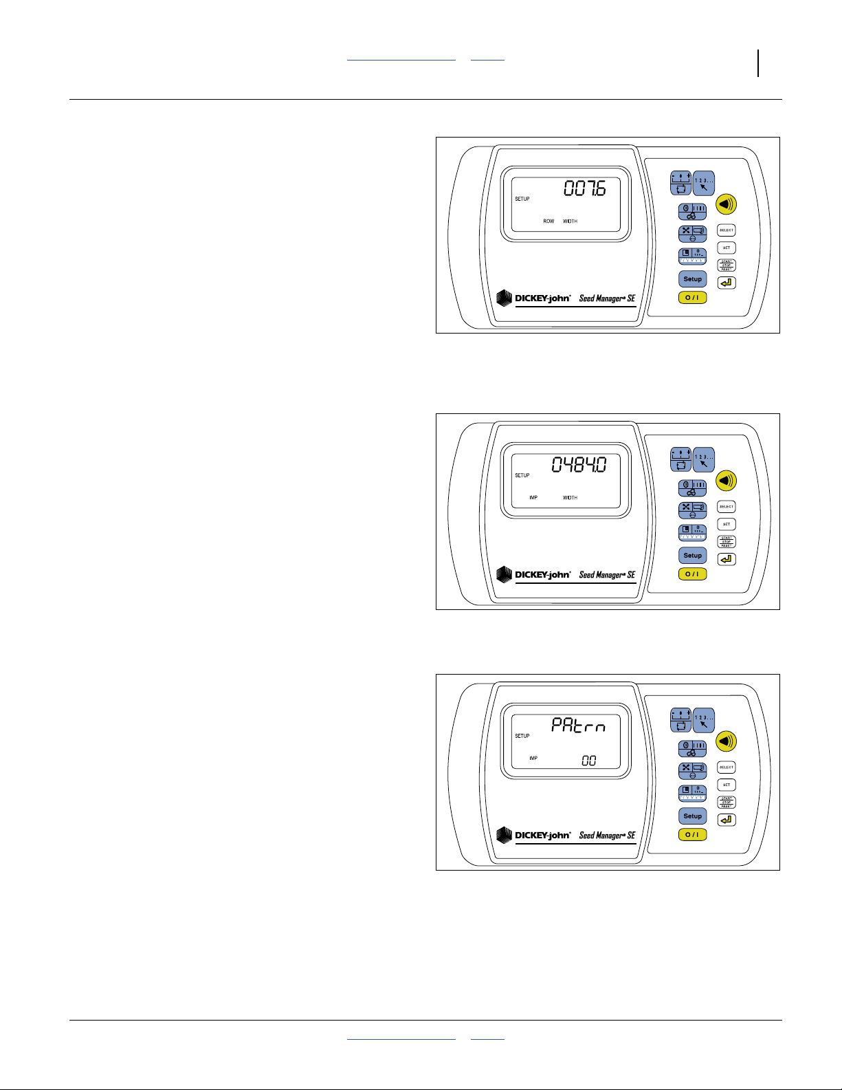
Refer to Figure 11
The monitor’s factory default is U.S. customary units of
measure (if “METRIC” is not displayed, the console is in
English/US customary units).
If metric units are desired, configure Setup Mode
Parameter 21 (Units) before making any other settings.
When Units are changed, all parameters with units have
their values converteda.
Figure 11
28343
Seed Monitor Units of Measure
Refer to Figure 12
Navigate to the parameter 8 screen (Automatic
Configuration). Press the START/STOP/RESET button to
run the auto-configuration.
When complete, the following parameters are
automatically set, and do not need to be entered:
P10 - Number of Seed Modules and Seed Sensors
P12 - Total Rows Configure
The seed monitor is not able to auto-detect everything it
needs to know about the drill. The next page has
cross-references to where to get the data needed.
Figure 12
28347
Configuration Auto-Detect
a. Note that this is different from how the hydraulic drive console operates when changing modes. See page 53.
196-538M Table of Contents Index 2014-01-29
Page 23
Great Plains Manufacturing, Inc. Table of Contents Index Preparation and Setup 19
Refer to Figure 13
At the parameter 4 screen (Row Width), enter the row
spacing of the drill (in inches or cm, to 0.1 precision).
Use the base row spacing, even if re-configuring for twin
row or split row operation.
Use the exact row spacing from the charts beginning on
page 176. If the chart shows a “swath-averaged”
spacing, use that figure. It accounts for irregular spacing
on TRS models and extra inches at wing joints. For
example, on a 64-row 7.5 inch (nominal spacing) drill,
the swath-average spacing is 7.56 in, or 7.6 in.
The monitor console uses Row Width, plus the
auto-detected row count, to calculate an Implement
Width. IMP WIDTH can vary slightly from the actual, due
to round-off. For a 64-row 7.6 in drill, it computes 0486.4,
Figure 13
Row Width (Spacing) Setup
28348
which is about half a percent too wide.
Refer to Figure 15
If, at the parameter 5 screen, the computed Implement
Width is not precise, you can override it to the value from
the charts beginning on page 176.
In the example at right, the computed “0486.4” has been
revised to the exact chart swath width of 484 inches.
If you operate with rows shut down for twin- or skip-row,
revise the Implement Width to the chart value for that drill
configuration. You do not need to alter the Row Spacing
parameter (the console accounts for the active row
configuration in the Split Row setup screen).
Refer to Figure 15
The parameter 9 screen configures which rows are
operating. The factory default is Pattern 00 (all rows).
This is correct for single-row (all rows), factory twin-row
and all-row TRS operations.
If you operate with rows shut down for twin- or skip-row,
change the Pattern number based on a comparison of
the pattern table in the DICKEY-john manual, and the
active rows from the charts beginning on page 176.
Also revise the Implement Width to the chart value for
that drill configuration. You do not need to alter the Row
Spacing parameter (the console accounts for the row
configuration in the Split setup screen).
Figure 14
Implement Width (Swath) Setup
Figure 15
Split Row Setup
28349
28350
2014-01-29 Table of Contents Index 196-538M
Page 24
20 3N-40P Table of Contents Index Great Plains Manufacturing, Inc.
Point Row Switch Module
Refer to Figure 16
15. Choose a tractor cab location where the module
does not obstruct vision, and the switches can be
safely operated during planting passes.
16. Route the power leads to a source of +12 Vdc
power capable of supplying 12.6A.
Color code is red+, black-.
Direct battery connection is acceptable; the
controller module has its own master switch and
fuse.
17. Use a tie to secure the power lead.
18. Route the controller harness to the tractor hitch.
Use ties to secure the hitch lead.
P
P
H
H
Drill Setup Checks
Hydraulic Bleed
Bleeding the hydraulic system is not a routine daily setup
item. If the system has not been charged since delivery,
or any hydraulic work has been done (such as installing
markers), “Bleeding Hydraulics” on page 145.
Drill Level
Drill sections are aligned and leveled at the factory, and
re-checked during dealer pre-delivery. Level normally
does not require routine adjustment before use. Great
Plains does recommend checking it once prior to first
field use. See “Level Frame Side to Side” on page 142.
Figure 16: 833-294C
Point Row Switch Module
28240
Drill Option Setup
Even if factory- or dealer-installed, some optional items
may need checking or adjustment prior to first field use.
Install any that were not pre-installed.
Scrapers (Option)
If scrapers were ordered, and not dealer-installed, install
them now per the instructions in one of the following
manuals, which are available on the Great Plains website
if not ordered or included:
Figure 17: 122-259K
10 & 20 Series Inside Scraper
20162
196-538M Table of Contents Index 2014-01-29
Page 25
Great Plains Manufacturing, Inc. Table of Contents Index Preparation and Setup 21
Marker Setup (Option)
If markers are not installed, install them now per the
instructions included with the markers.
Once installed, verify that they have been correctly bled
(See “Bleeding Markers” on page 147).
Set initial marker extension - the distance to the mark on
each side from the outside row unit on that side.
1. Move the hitched drill to a typical flat field.
2. Extend a marker on one side (see page 36). Pull
forward a few feet or a meter or so to leave a mark.
3. Measure from the centerline of the outside row unit
(whether that row unit is to be used or not) to the
mark, along a line parallel to the wing.
Refer to Figure 230 through Figure 235 on pages 176 and 178
4. Check the measurement against the value
recommended by Great Plains.
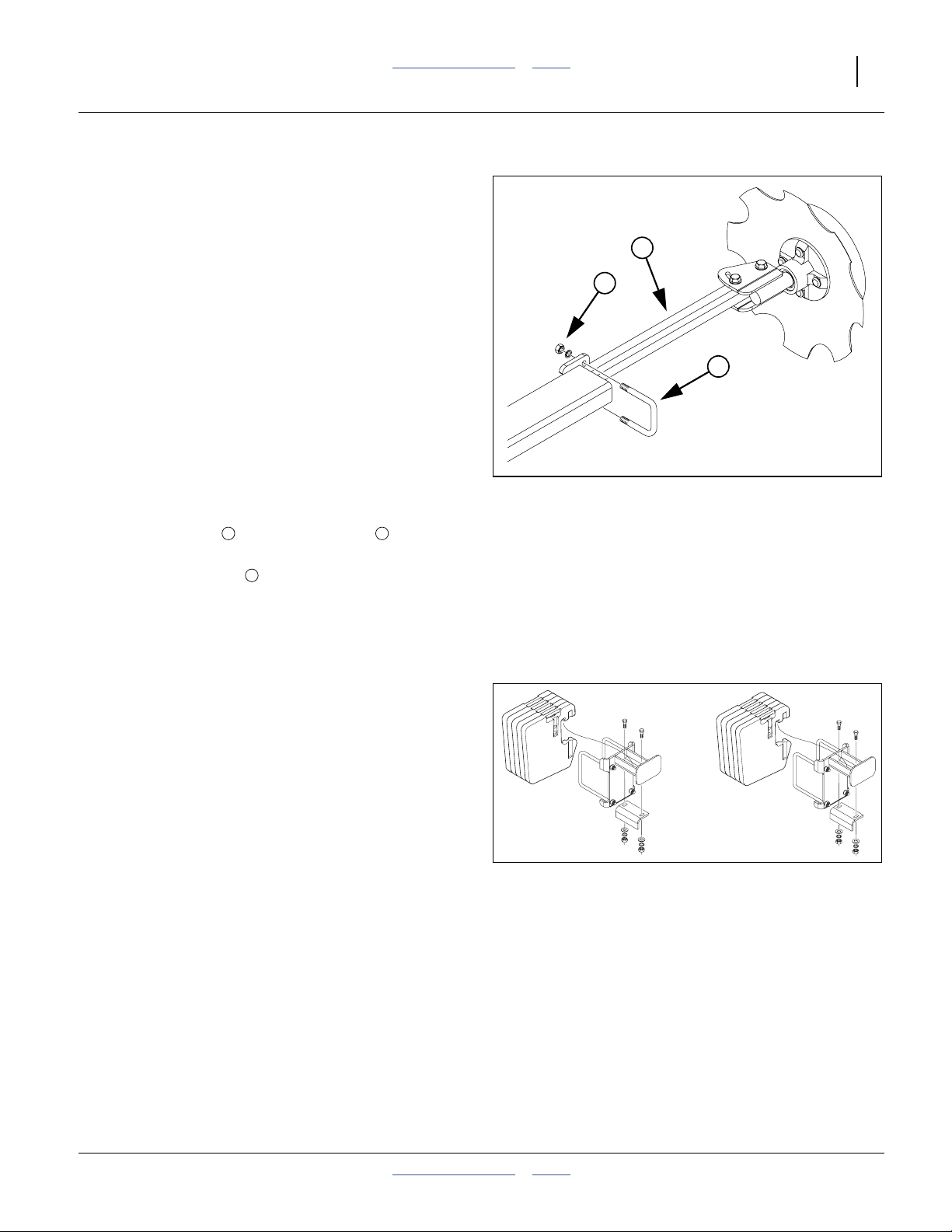
Refer to Figure 18
If the marker extensions need adjustment:
5. Loosen the nuts securing the U-bolt at the
outer marker section.
6. Slide the inner tube in or out, and re-secure nuts.
See page 94 for further marker adjustments. Re-check
marker extension when changing disk angle, or when
inverting the disk, as both adjustments change the
position of the centerline of the mark.
1 2
3
3
1
2
Figure 18
Adjusting Marker Extension
18878
Install Weight Brackets (Option)
If weight brackets were ordered, and were not
dealer-installed, install them now. Two kits (4 brackets)
are supported, accepting five standard
100 pound (45 kg) “suitcase” tractor weights each, for a
maximum additional weight of 2000 pounds (907 kg).
Each empty bracket kits adds 121 pounds (55 kg) to the
drill. Weights are not included with kits.
If only one weight kit is to be installed, use the “Outer”
position.
Once the brackets are installed, see “Frame Weight”on
page 93 for operating information.
Figure 19:
Weight Bracket Kit and Weights
27068
2014-01-29 Table of Contents Index 196-538M
Page 26
22 3N-40P Table of Contents Index Great Plains Manufacturing, Inc.
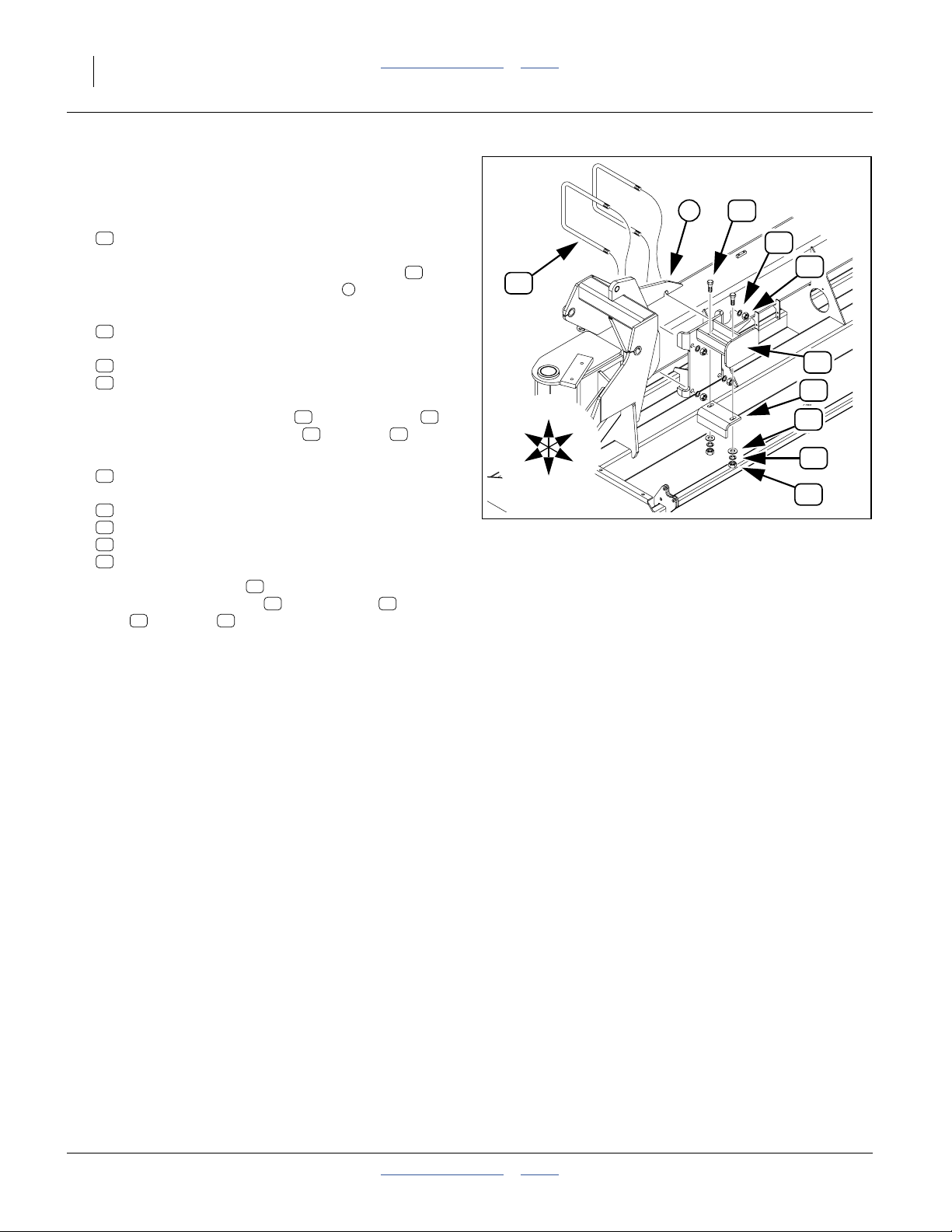
Install Outer Brackets
Start with the left wing.
Refer to Figure 20
1. Select two:
19
806-172C U-BOLT 3/4-10 X 10 1/32X11 1/2
From the front of the wing, insert the U-Bolts
through the holes in the outside lug .
1
19
1
19
13
18
15
2. Select one:
11
196-291H 40P WEIGHT BRACKET WLDMNT
and four sets:
18
804-023C WASHER LOCK SPRING 3/4 PLT
15
803-027C NUT HEX 3/4-10 PLT
Mount the bracket weldment on the U-Bolts ,
and secure with lock washers and nuts .
11 19
18 15
3. Select one:
12
197-062D WEIGHT BRACKET ADJ LEG
and two sets:
13
802-057C HHCS 5/8-11X2 1/4 GR5
16
804-019C WASHER FLAT 5/8 USS PLT
17
804-022C WASHER LOCK SPRING 5/8 PLT
14
803-021C NUT HEX 5/8-11 PLT
Orient the adjustment leg toward the outside (end of
wing), and secure with bolts , flat washers , lock
washers and nuts .
17 14
12
13 16
U
F
L
R
B
D
Figure 20
Weight Bracket, Outer
11
12
16
17
14
20323
4. Repeat step 1 through step 3 for the right wing.
196-538M Table of Contents Index 2014-01-29
Page 27
Great Plains Manufacturing, Inc. Table of Contents Index Preparation and Setup 23
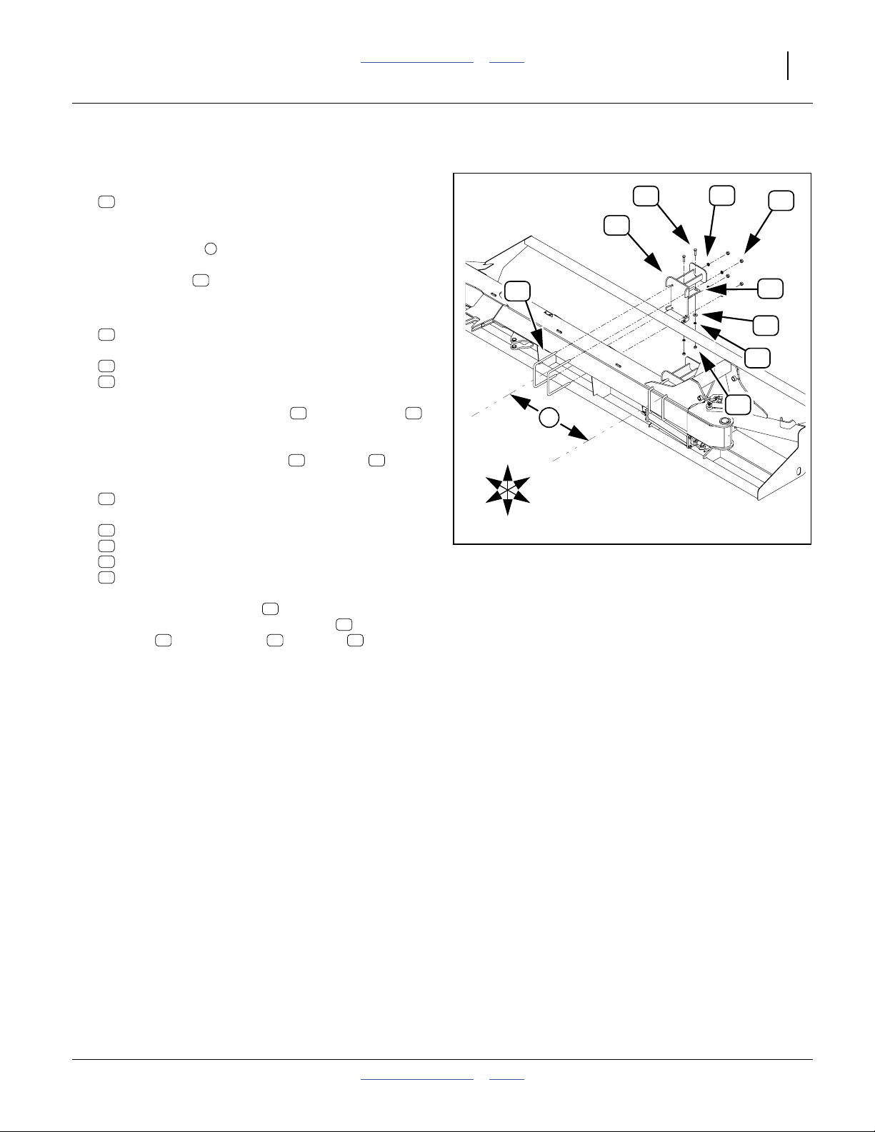
Install Mid-Wing Brackets
Refer to Figure 21
5. Select two:
19
806-172C U-BOLT 3/4-10 X 10 1/32X11 1/2
13
18
15
From the centerline of the inside U-Bolt installed at
step 1, measure toward center, approximately:
1
35
⁄2inch (90 cm)
Insert a U-bolt from drill front, under the hoses.
2
19
Insert the second U-bolt 71⁄2inch (19 cm) further in.
6. Select one:
11
196-291H 40P WEIGHT BRACKET WLDMNT
and four sets:
18
804-023C WASHER LOCK SPRING 3/4 PLT
15
803-027C NUT HEX 3/4-10 PLT
Position the bracket weldment on the U-Bolts ,
11 19
and adjust the placement as necessary to clear tube
weldments, web plates, grease banks, marker parts
and secure with lock washers and nuts .
18 15
7. Select one:
12
197-062D WEIGHT BRACKET ADJ LEG
and two sets:
13
802-057C HHCS 5/8-11X2 1/4 GR5
16
804-019C WASHER FLAT 5/8 USS PLT
17
804-022C WASHER LOCK SPRING 5/8 PLT
14
803-021C NUT HEX 5/8-11 PLT
Orient the adjustment leg toward the inside
(center of drill), and secure with bolts , flat
washers , lock washers and nuts .
16 17 14
12
13
8. Repeat step 5 through step 7 for the right wing.
R
F
U
D
19
11
2
B
L
Figure 21
Weight Bracket, Mid-Wing
12
16
17
14
28243
2014-01-29 Table of Contents Index 196-538M
Page 28
24 3N-40P Table of Contents Index Great Plains Manufacturing, Inc.
Operating Instructions
This section covers general operating procedures. It
assumes that setup items have been completed.
Experience, machine familiarity and this information
leads to efficient operation and good working habits.
Always operate farm machinery with safety in mind.
Pre-Start Checklist
❑ Review “Important Safety Information” on page 1.
❑ Lubricate the drill as indicated under Lubrication,
“Maintenance and Lubrication” on page 137.
❑ Check the tires for proper inflation according to “Tire
Inflation Chart” on page 174.
❑ Check for worn or damaged parts and repair or
replace before going to the field.
❑ Check all nuts, bolts and screws. Tighten bolts as
specified on “Torque Values Chart” on page 175
❑ Check hydraulic hoses, fittings and cylinders for
leaks. Tighten, repair or replace before planting.
High Pressure Fluid Hazard:
Escaping fluid under pressure can penetrate skin, causing
serious injury. Avoid the hazard by relieving pressure before
disconnecting hydraulic lines. Use a piece of paper or
cardboard, NOT BODY PARTS, to check for leaks. Wear
protective gloves and safety glasses or goggles when working
with hydraulic systems. If an accident occurs, seek immediate
medical attention from a physician familiar with this type of
injury.
Moving Chain Hazard
Pinch/Crush Hazard
Shaft Entanglement Hazard:
Be careful when working around drill while tractor is running.
Any movement detected by the radar gun (Figure 22) can
activate the Veris hydraulic drive causing motion of chains,
sprockets, shafts and seed meters.
Vision Hazard:
The DICKEY-john RVS II radar speed sensor is an intentional
radiator of RF energy. Although its radiated energy level is far
below the limits set by EN 61010-1: 1993\A2: 1995 - Chapter
12.4, it is advisable not to look directly into the face of the unit.
The radar must radiate toward the ground and at least 20 cm
(8 inches) away from a human during use to comply with the
RF human exposure limits per FCC 47 CFR Sec. 2.1091.
DO NOT mount or use the radar in a manner inconsistent with
its defined use.
196-538M Table of Contents Index 2014-01-29
Figure 22
DICKEY-john Radar
20310
Page 29

Great Plains Manufacturing, Inc. Table of Contents Index Operating Instructions 25
Lift / Lower
Machine Damage Risk:
Lower only when the drill is unfolded. The drill must be raised
and locked up for folding and unfolding.
The drill has six rephasing lift cylinders that raise and
lower the opener frame.
Six (6) transport locks are provided, two for the rockshaft
(center forward) cylinders, and one each for the rear and
wing caster cylinders. These assure that the drill stays
raised during folding/unfolding, transport, storage,
lubrication, maintenance and some setup/adjustment
tasks.
Opener Operation Lowered
The “lowered” position of the opener frame is regulated
by an adjustable valve, factory set for 2 inch coulter
depth. See “Frame Height” on page 72 for adjustment.
Figure 23
Transport Locks Installed
20264
20266
Rephasing Lift System
Over a period of normal use the cylinders may get out of
phase. This causes some implement sections to run
higher than others when lowered. To minimize this, or
rephase the cylinders, make the following steps your
normal raise sequence:
9. Raise drill completely and hold the hydraulic remote
lever on for several seconds until all cylinders are
fully extended. Do this every third or fourth time you
raise the drill out of the ground.
10. When all cylinders are fully extended, momentarily
reverse the hydraulic remote lever to retract the
system1⁄2inch (13 mm) to maintain levelness.
If implement is still not level after re-phasing, “Bleeding
Lift Hydraulics” on page 145 and “Level Frame Side to
Side” on page 142.
Figure 24
Lock Channel Storage
20268
20269
2014-01-29 Table of Contents Index 196-538M
Page 30
26 3N-40P Table of Contents Index Great Plains Manufacturing, Inc.
Lift Cylinder Lock-Up
When moving the raised drill more than a short distance,
or over any public road, or when performing adjustments
or maintenance, do not rely solely on the lift cylinders to
keep the mainframe raised.
Install transport locks.
Refer to Figure 25
1. If drill is folded, confirm hitch is in Float.
If drill is unfolded, hitch may be in any configuration.
2. Raise the drill mainframe. See “Lift / Lower” on
page 25.
3. Remove the transport locks from their storage
positions . Install the transport locks on the
cylinder rods , securing them with the same pins
used for storage.
4. Lower the lift cylinders onto the locks.
1
2
2
2
1
1
Figure 25
Lift Cylinder Locks Installed
29283
Folding the Drill
Machine Damage Risk:
Fold only when the drill is raised and locked up.
Fold the drill on level ground with the tractor in neutral.
If your drill has markers, be certain they are folded and
their control switches are off before folding.
Pinch Point and Crushing Hazard. To prevent serious injury
or death:
▲ Always use transport lift locks when drill is folded.
▲ Fold only if hydraulics are bled free of air and fully charged
with hydraulic oil.
▲ Stay away from frame sections when they are being raised
or lowered.
▲ Keep away and keep others away when folding drill.
Refer to Figure 26
1. Set Drive/Lock selector valve to Lock.
Figure 26
Fold: Drive/Lock Selector Valve
Drill Center section moves back while folding. Tractor may
move forward. Allow at least 10 feet (3 m) clearance behind
drill and ahead of tractor when folding.
21844
196-538M Table of Contents Index 2014-01-29
Page 31

Great Plains Manufacturing, Inc. Table of Contents Index Operating Instructions 27
2. Fold markers (Option). See page 36.
3. Raise drill with lift cylinders until cylinders are fully
extended. Install lock channels over extended
wheel-cylinder rods. Six cylinder rods total. See
page 25.
4. Retract the Lock cylinder circuit lever to:
• disengage the tool bar locks (2),
• disengage swivel locks (2),
• disengage caster locks (2), and
• enable the self-latching transport lock (1).
Figure 27
Transport/Tool Bar Lock Cylinders
21841
21845
Set circuit to Neutral. Do not Extend.
Note: There are two key points to remember when
operating the lock cylinders.
a. All seven lock cylinders are plumbed together,
and all move at the same time.
b. Operate the lock circuit lever (Retract/Neutral)
only once to fold. As the cylinders move, they
unlock 6 points then stop in a “ready to fold
position.” When the drill is folded, the 7th lock,
spring loaded, snaps shut, locking the drill.
5. Extend the Fold cylinder circuit lever to slowly fold
wings forward. The transport lock automatically
captures the right wing tool bar for transport.
Note: It may be necessary to ease forward slightly with
the tractor to assist wings in folding completely.
Figure 28
Swivel Lock Cylinder
27183
2014-01-29 Table of Contents Index 196-538M
Page 32

28 3N-40P Table of Contents Index Great Plains Manufacturing, Inc.
Unfolding the Drill
Machine Damage Risk:
Unfold only when the drill is raised and locked up.
Unfold the drill on level ground with the tractor
transmission in neutral.
Crushing, Pinch-Point and Overhead Hazards. To prevent
serious injury or death:
▲ Always use transport locks when drill is folded.
▲ Fold only if hydraulics are bled free of air and fully charged
with hydraulic oil.
▲ Stay away from frame sections when they are being raised
or lowered.
▲ Keep away and keep others away when unfoldingdrill.
Note: When unfolding, operate the lock circuit exactly in
reverse of folding. Operate the circuit once
(Extend/Neutral). Remember that when the
cylinders move, they release one lock, and enable
six others, stopping in a “ready to unfold” position.
As the drill is unfolded, the six spring loaded locks
snap shut, locking the drill.
Refer to Figure 29
1. Check selector valve set to Locks.
2. Extend the Lock cylinder circuit lever to:
• disengage the self-latching transport lock,
• enable two tool bar locks,
• enable two swivel locks, and
• enable two caster locks.
Set circuit to Neutral. Do not Retract.
Refer to Figure 23 and 25 on page 25
3. Raise the drill. Remove lock channels from all six
wheel cylinders. Store lock channels.
4. Activate fold hydraulics and slowly unfold the until
wings are fully unfolded and all spring loaded locks
have snapped into position.
5. Lower the drill.
Refer to Figure 29
6. Move selector valve handle from Locks to Drive.
Figure 29
Unfold: Drive/Lock Selector Valve
Pinch/Crush Risk:
Center section of drill moves forward while unfolding.
Tractor may move backward. Keep all personnel clear of drill
and tractor wheels.
Figure 30
Transport/Tool Bar Lock Cylinders
Figure 31
Caster Lock Cylinder
21844
21841
21845
21842
196-538M Table of Contents Index 2014-01-29
Page 33

Great Plains Manufacturing, Inc. Table of Contents Index Operating Instructions 29
Transport
Electrocution Hazard. To prevent serious injury or death from
electric shock, keep clear of overhead power lines when
transporting, folding, unfolding or operating drill components.
Machine is not grounded. At higher voltages, electrocution can
occur without direct contact.
Great Plains recommends transporting the drill without
seed loaded. Although designed for highway movement
with full seed boxes, the additional weight of seed may
cause the drill to exceed the rated towing and stopping
ability of the tractor, makes the drill more difficult to
control and stop, and increases wear on tires and wheel
bearings.
Make sure the tractor weighs at least
drill, including any material load. Check the table on
page 30 for typical weights of various configurations.
2
⁄3(67%) of the
Loss of Control Hazard:
Towing the drill at high speeds or with a vehicle that is not
heavy enough can lead to loss of vehicle control. Loss of
vehicle control can lead to serious road accidents, injury and
death. To reduce the hazard:
▲ Do not exceed 20 mph (32 kph).
▲ Do not tow a drill that weighs more than 1.5 times the
weight of the towing vehicle.
Pre-Transport Checklist
Before transporting the drill, check the following items.
❑ Make sure the weight of the tractor equals or
exceeds the value specified for your drill
configuration.
❑ Marker Checklist Complete: Markers must be
folded.
❑ Master Switches Off: Check that the Veris and point
row (if any) master switches are off while
transporting.
❑ Drill Raised and Locked: Lift transport locks
installed. Wings folded and locked, with circuit lever
in neutral.
❑ Tires: Check that all tires are properly inflated as
listed on “Tire Inflation Chart” on page 174.
❑ Bystanders: Check that no one is in the way before
moving. Do not allow any one to ride on the drill.
Figure 32
18857
Marker in Transport Cradle
❑ Warning Lights: Always use tractor and drill
warning lights when transporting the drill.
❑ Clearance: Know the maximum dimensions of the
tractor and drill in transport position and follow a
route that provides adequate clearance from all
obstructions, including overhead lines.
See “Specifications and Capacities” on page 170.
❑ Stopping Distance: Allow sufficient stopping
distance and reduce speed prior to any turns or
maneuvers. If the drill is transported full, allow extra
stopping distance.
❑ Road Rules: Comply with all national, regional and
local laws when transporting on public roads.
❑ Watch Traffic: The drill boxes obstruct a portion of
your rear view. Be prepared for sudden maneuvers
from following vehicles.
2014-01-29 Table of Contents Index 196-538M
Page 34

30 3N-40P Table of Contents Index Great Plains Manufacturing, Inc.
Typical Drill Weights
a
a. Weights include frame-mounted coulters and typical press wheels, but not row unit accessories or other options, which can alter the
total weight substantially. If table weight is near recommended limit for the tractor, obtain a precise weight for the empty drill at a scale.
196-538M Table of Contents Index 2014-01-29
Page 35

Great Plains Manufacturing, Inc. Table of Contents Index Operating Instructions 31
Loading Seed
To unload seed, “Cleaning Out Meters” on page 138.
Misstep Hazard:
Watch your step when walking on drill ladder and walkboard.
Falling from drill could cause severe injury or death.
Great Plains recommends loading materials after the drill
has been transported to the planting ground.
Seed is heavy. A full load of dense seed adds over
6000 pounds (2780 kg) to the drill. Pre-loading
substantially increases transport hazards:
• Stopping distance increases.
• Turns are more difficult to initiate and more difficult to
stop, due to the inertia of the load.
To load materials:
1. Load only in dry conditions.
2. If the seed is treated, wear protective equipment
recommended for the hazards.
3. Lower the drill.
4. Open the lids for the boxes.
5. Remove any debris or obstructions from the boxes. If
other seed needs to be first removed, see “Cleaning
Out Meters” on page 138.
6. If not planting all rows, shut off unused rows. See
page 79.
7. If seed lubricant is to be used, and was not
re-applied to the seed, determine the total amount to
be added, and place a small amount of it in the
empty seed boxes.
8. Load seed. Load or spread materials evenly across
all partitions. Use a tool or gloved hand. Add seed
lubricant periodically (every other bag or so).
9. Make a note of the seed quantity loaded, for later
confirmation of population or application density
desired.
10. Close and secure the box lids.
WARNING
To avoid serious injury or death:
Watch your step when climbing ladder or
walking on walkboard.
838-102C
838-102C
818-323C
25477
2014-01-29 Table of Contents Index 196-538M
Page 36

32 3N-40P Table of Contents Index Great Plains Manufacturing, Inc.
Seed Lubricants
29248
Singulator Plus Meters (all seeds)
Ezee Glide Plus Talc-Graphite Mix
821-069C bucket, 5 gallon (19 liter)
Ezee Glide Plus Lubricant
To maximize performance of Great Plains metering
systems, it is imperative to use only “Ezee Glide Plus”
lubricant. “Ezee Glide Plus” Talc-Graphite lubricant is
mandatory for all seeds, especially treated or inoculated
seed. Thorough mixing of seed and added lubricant is
required.
Recommended usage:
For clean seeds other than milo and cotton sprinkle
one cup of Ezee Glide Plus Talc per 4 bushels or units
(170 ml per 100 liters) of seed.
For milo and cotton double the application to
one cup (or more) per 2 bushels or units (335 ml per
100 liters) of seed.
Adjust this rate as necessary so all seeds become
coated while avoiding an accumulation of lubricant in the
bottom of the hopper.
For seed with excessive treatment, or for humid planting
environments, increase the rate as needed for smooth
meter operation.
25477
Finger Pickup Meters
EZ-Slide Graphite Powder
821-042C bottle, 1 pound (450 grams)
821-060C jug, 5 pound (2.3 kg)
For Finger Pick Up Meters Only
Use only approved Graphite Powder available from Great
Plains Mfg. Inc. or Precision Planting to ensure proper
lubrication of finger pickup corn seed meters.
Recommended usage:
For finger pickup meters, add one tablespoon (15 ml) of
graphite for each unit of seed corn (80,000 kernels).
In high humidity conditions, or seeds with heavy seed
treatments, increase the application to two tablespoons
(30 ml).
If delivery of seed from the hopper to the finger meter is
an issue, add “Ezee Glide Plus” talc and graphite blend
at a rate of one cup (237 ml) per 4 units of seed. Adjust
until issue is resolved.
Irritation and Chronic Exposure Hazard:
Wear gloves. DO NOT use hands or any part of your body to
mix seed lubricant. Wear a respirator when transferring and
mixing. Avoid breathing lubricant dust. Not an acute hazard.
May cause mechanical eye or skin irritation in high
concentrations. As with all mineral spills, minimize dusting
during clean-up. Prolonged inhalation may cause lung injury.
Product can become slippery when wet.
196-538M Table of Contents Index 2014-01-29
Irritation and Chronic Exposure Hazard:
Wear gloves. DO NOT use hands or any part of your body to
mix seed lubricant. Wear a respirator when transferring and
mixing. Avoid breathing lubricant dust. Not an acute hazard.
May cause mechanical eye or skin irritation in high
concentrations. As with all mineral spills, minimize dusting
during clean-up. Prolonged inhalation may cause lung injury.
Page 37

Great Plains Manufacturing, Inc. Table of Contents Index Operating Instructions 33
Planting
Seed Rate
Seed rate on this family of drills is controlled by:
• selection of seed meter, and seed wheel or finger
count, and
• the rate set on the hydraulic drive console.
About Hydraulic Drive Rate
Before it can control seed rate, the hydraulic drive
console must be:
• configured with information about your drill and
intended planting speed,
• configured with a calibration number for the seed,
meter and rate range, and;
• calibrated to fine-tune the seed rate calibration
number and ground speed radar. Calibration is
essential for volumetric seeds, because the seed
metered by each meter wheel revolution varies with
the seed.
Calibration is described starting on page 42.
Refer to Figure 33
With those steps completed, field seeding rate is
controlled manually by adjusting the target “set=” rate
using the ⇑/⇓ arrow buttons. Rate can also be controlled
by a pre-loaded “recipe” or an external GPS controller.
In field operation, the hydraulic drive console displays:
set= the currently active desired seeding rate
out= the current system seeding rate
spd= (over number), the current speed
Figure 33
Console Planting Display
25295
28334
Seeding Depth
Refer to Figure 33
Seeding depth is controlled by one or more of:
• frame-mounted coulter depth (if present),
1
2
• unit-mounted coulter depth (if present),
• side depth gauge wheel (Series dependent), and;
• and press-wheel height (Series dependent).
3
2
Adjust frame height first (page 72), then make row unit
adjustments. Each opener Series is covered separately:
10 Series page 95
10HD Series page 100
20 Series page 109
Figure 34
10HD Seeding Depth
25 Series page 115
2014-01-29 Table of Contents Index 196-538M
3
1
27070
Page 38

34 3N-40P Table of Contents Index Great Plains Manufacturing, Inc.
Point Row Switches
The hydraulic drive motor operates whenever the speed
radar detects motion. The Point Row system determines
whether or not that motion is coupled to the meter drives,
by controlling the electric clutches. The implement lift
switch is part of the Point Row system.
A Point Row troubleshooting chart is found on page 129.
Refer to Figure 35
Note: The Pump switch has no function on 3N-40P
drills configured byGreat Plains. Unless connected
to aftermarket equipment, leave it off.
P
When Not Planting or Calibrating
Set the Master switch OFF when you do not intend to
meter seed.
Entanglement Hazard:
If the hydraulic drive system is on, and the drill is lowered (or
the Master switch is in CAL), unexpected motion of chains,
sprockets, shafts and seed meters can occur if the speed radar
detects motion, such as someone moving near the radar.
M
Normal Full Pass
1. Set Master switch ON (up)
Set all sections ON (up).
Check that corresponding lamps are on.
2. Height switch automatically energizes clutches when
row units are lowered.
M
L C R
Point Row in Pass
3. Turn desired sections off as non-planting regions are
reached.
4. Turn the sections back on before commencing next
full-width pass.
Point Row CAL Mode
When the drill is raised, the lift switch normally causes
the Point Row Monitor to disengage the clutches for each
drill section. To keep one or more clutches engaged
during hydraulic drive calibration, set the Master switch
to CAL.
For a typical 3-row calibration, set the Left section
switch on, and the center and right section
switches / off during calibration.
L
C R
{
S
L
F
Cab Switch Box
RC
CAL
Figure 35
P
Switch
or
Function
Indicator
MASTER
M
Switch
MASTER
m
S
C
R
P
CAL
Lamp
Section
Lamps
L
LEFT
CENTER
RIGHT
PUMP
F
Fuse
CAL Lamp
a. However, the section’s meters may still be coupled
to the drive system, if lock-up bolts are installed in
the clutch. See page 149.
m M
b. If lamp fails to illuminate with set ON, check
the fuse . If open, check for damaged cable /
failed clutch.
Up: ON: System enabled
Center: OFF System inactive
Down: CAL: Lift switch bypassed on
On: System enabled
Off: System OFF
On: Clutch enabled for that section.
Off: Clutch not energized
Up: section enabled
Down: section disabled
May control customer-provisioned
equipment.
Protects switch box, clutches and
b
battery.
On: Lift switch overridden
Off: Lift switch active (or system off)
F
a
M
28246
196-538M Table of Contents Index 2014-01-29
Page 39

Great Plains Manufacturing, Inc. Table of Contents Index Operating Instructions 35
Field Operations
This section presumes that all pre-operation checks have
been made on drill, and drill is hitched and loaded with
seed.
Final Field Checklist
❑ Drill unfolded and raised.
❑ Selector valve set to hydraulic drive.
❑ Hydraulic drive console set per seed rate calibration.
❑ Check all seed tubes secure.
❑ Check all row configurations identical (except where
compensating for tire tracks, etc.).
If you desire to verify that all meters and seed tubes are
working, you can run a Veris calibration for 4 seconds
(the minimum time) and “KEEP OLD” when it presents a
proposed new calibration number. See page 42.
Planting Sequence
1. All Clutch/Point Row switches up (except Pump).
Check lamps illuminated.
2. Press Veris “ON/VR” button once.
Check LED above button illuminated.
3. Pull forward to field.
4. Lower drill to field position.
5. Move lever for hydraulic drive circuit forward and lock
it open.
6. Option: Extend marker side desired.
7. Option: Shaft Monitor ON
8. Press Veris “ENGAGE” button once.
Check LED above button illuminated.
9. Accelerate to planting speed.
10. Raise drill for turns (drive stops automatically).
11. Option: Retract and extend markers at turns.
Stop early in the first pass to verify:
• Openers are at correct depth.
• Seed is flowing to furrows.
• Press wheels are covering furrows as desired.
Monitor the seed level indicators on the seed box. After a
third or more of the first seed load has been planted, stop
and check the seed boxes from above. Observe seed
monitor for row out-of-limit alarms.
Seed consumption is uneven, and end rows run out
before mid-section rows. Re-load seed when the level
indicators near Empty.
Figure 36
DICKEY-john Radar
Moving Chain Hazard
Pinch/Crush Hazard
Shaft Entanglement Hazard:
Be careful when working around drill while tractor is running.
Any movement detected by the radar gun can activate the Veris
hydraulic drive causing motion of chains, sprockets, shafts and
seed meters.
Vision Hazard:
The DICKEY-john RVS II radar speed sensor is an intentional
radiator of RF energy. Although its radiated energy level is far
below the limits set by EN 61010-1: 1993\A2: 1995 - Chapter
12.4, it is advisable not to look directly into the face of the unit.
The radar must radiate toward the ground and at least 20 cm
(8 inches) away from a human during use to comply with the
RF human exposure limits per FCC 47 CFR Sec. 2.1091.
DO NOT mount or use the radar in a manner inconsistent with
its defined use.
Certain Machine Damage:
Do not back up with openers in the ground. To do so will cause
severe damage and opener plugging.
20310
2014-01-29 Table of Contents Index 196-538M
Page 40

36 3N-40P Table of Contents Index Great Plains Manufacturing, Inc.
Marker Operation (Option)
Markers are on a separate hydraulic circuit on the drill.
Before operating markers, make sure they are properly
bled as described in “Bleeding Markers” on page 147.
Dual markers are equipped with a sequence valve to
control lift sequence. Starting with both markers up, the
sequence is:
1. Activate tractor hydraulic lever; right marker lowers
while left marker stays up.
2. Reverse hydraulic lever; right marker raises while left
marker stays up.
3. Activate hydraulic lever; left marker lowers while right
marker stays up.
4. Reverse hydraulic lever; left marker raises while right
marker stays up.
5. Pattern repeats.
Folding speed of dual markers is adjusted with
adjustment screws on sequence valve body. Because
excessive folding speed may damage markers, adjust
markers to a safe folding speed according to “Marker
Speed” on page 147.
Note: To get both markers in the lowered position at the
same time, activate hydraulic lever to lower one
marker. After marker is lowered, move lever to
opposite position then quickly reverse lever and
hold until other marker is lowered.
196-538M Table of Contents Index 2014-01-29
Page 41

Great Plains Manufacturing, Inc. Table of Contents Index Operating Instructions 37
Parking
Following these steps when parking the drill for periods
of less than 36 hours. For longer periods, see Storage,
the next topic.
1. Spot the drill on firm, level ground.
2. Raise the drill. Install transport locks.
3. Fold as necessary for the parking space available.
4. Securely block drill tires to prevent rolling.
Roll-Away Hazard
Always block drill tires when unhitching. There is not enough
weight on tongue to anchor drill using parking jack.
Do NOT unhitch on a steep slope.
Always unhook safety chain LAST.
Figure 37
Drill on Parking Stand
20273
Storage
Store the drill where children do not play. If possible,
store inside for longer life, or cover with tarp.
5. Unload seed boxes.
6. Lubricate the drill at all points listed under
“Lubrication” on page 154.
7. Check all bolts, pins, fittings and hoses. Tighten,
repair or replace parts as needed.
8. Check all moving parts for wear or damage. Make
notes of any parts needing repair before the next
season.
9. Plug or cap seed delivery tubes to prevent pest entry.
10. Grease exposed cylinder rods to prevent rust. Be
sure to completely de-grease before next use, to
prevent seal damage.
11. Use touch-up paint to cover scratches, chips and
worn areas to prevent rust.
2014-01-29 Table of Contents Index 196-538M
Page 42

38 3N-40P Table of Contents Index Great Plains Manufacturing, Inc.
Hydraulic Drive Operation
Seeding rate on the 3N-40P family is controlled entirely
seed meter wheel selection, and by the seed monitor
and the hydraulic drive. This section of the manual
describes monitor setup and operation.
Drive Operational Requirements
Hydraulic System:
Closed Center, pressure compensated or load sensed
systems only
Drive will not operate on Open-Center hydraulic systems
Minimum Hydraulic Pressure 2250 psi
Maximum Hydraulic Pressure 3000 psi
Maximum Required Flow 8.5 gpm
Electrical System:
Voltage 12 volts DC
Current 4 amperes
Tractor Hookup
High Pressure Fluid Hazard: Escaping fluid under pressure
can penetrate skin, causing serious injury. Avoid the hazard by
relieving pressure before disconnecting hydraulic lines. Use a
piece of paper or cardboard, NOT BODY PARTS, to check for
leaks. Wear protective gloves and safety glasses or goggles
when working with hydraulic systems. If an accident occurs,
seek immediate medical attention from a physician familiar
with this type of injury.
22715
Hydraulics:
1. Connect pressure hose (P) to retraction outlet
2. Connect motor return hose (T) to motor return port (if
available) or to extension outlet.
3. Set flow rate at maximum required flow of 13 gpm.
4. If tractor is equipped with electro-hydraulic valves,
set timer to “constant” flow.
Electrical:
Refer to Figure 38
Power must be connected directly to the battery. Make
sure that eyelets are properly connected (red to positive,
black to negative). Connect female socket to power port
adapter.
Disconnect all cables and remove VER-21568 Ext. Control
module before welding on drill. See page 137.
Moving Chain Hazard: Return hydraulic drive circuit lever to
Neutral before exiting tractor cab. Unexpected drive rotation
can cause serious injury.
Figure 38
Controller Electrical Connection
22714
196-538M Table of Contents Index 2014-01-29
Page 43

Great Plains Manufacturing, Inc. Table of Contents Index Hydraulic Drive Operation 39
Controller Menu
ON / VR
set= * spd=
PRESET RATES
PRESET
selected
PRESET 1
*
PRESET 2
*
PRESET 3
*
FUNCTION
FUNCTION
FUNCTION
FUNCTION
SPEED CALIBRATION
UP:CALIBRATE
DN:RESTORE
CAL SETTINGS
*
FUNCTION
PRESS ENGAGE
AT 1 ST F LAG
ENGAGE
___ft ENGAGE AT
2ND FLAG
ENGAGE
DISTANCE ERROR
____%
FUNCTION
UP:CALCULATE NEW
DN:KEEP CURRENT
KEY
set = * spd=
out = ______ _. _
FUNCTION ENGAGE
ON / VR
- cab console LCD screen
- Condition for progressing to next screen
* Adjust number up/down or toggle between selections using
the keys.
** Refer to the troubleshooting section of the manual for a
description of error messages.
out= ______ _._
FUNCTION
CALIBRATION
NUMBER *
FUNCTION
recipe format
*
VERIS V1
selected
FUNCTION
manual/preset
*
MANUAL
selected
FUNCTION
PRESS UP KEY TO
CALIBRATE RATE
FUNCTION
PRESS UP KEY TO
CALIBRATE SPEED
FUNCTION
- Keys on cab console
VARIABLE RATE
FUNCTION
RAWSON NOMINAL
*
RAWSON
selected
FUNCTION
FUNCTION
invalid
time
**
ENGAGE
FUNCTION:EXIT
FUNCTION
RATE CALIBRATION
CAL SETTINGS
*
CAL SETTINGS
WIDTH *
CAL SETTINGS
# ROWS *
CAL SETTINGS
SPEED *
ENTER TARGET
AMOUNT *
FUNCTION
FUNCTION
calibration
error
**
valid
time
TIME TO RUN FOR
CAL ___s
CLEAR DRIVE AREA
UP:CLEAR DN:EXIT
ENGAGE:RUN DRIVE
FUNCT:EXIT
___s out= ______
ENGAGE TO STOP
ENTER AMOUNT
COLLECTED *
NEW CAL #: ____
OLD CAL #: ____
UP:KEEP NEW
DN:KEEP OLD
FUNCTION
FUNCTION
FUNCTION
FUNCTION
FUNCTION
FUNCTION
ENGAGE
calibration
successful
FUNCTION
FUNCTION
23251
2014-01-29 Table of Contents Index 196-538M
Page 44

40 3N-40P Table of Contents Index Great Plains Manufacturing, Inc.
Console Functions
Refer to Figure 39 (depicting the console in Manual mode)
• ON/VR button:
turns drive system on.
Press twice for VR (Variable Rate) mode.
Note:
• OFF button:
used to shut off Console.
Note: This also turns off power to the external
controller module and ground speed radar.
• FUNCTION button:
used in Calibration modes, and to programming
Presets and downloading recipes.
• ⇑/⇓ Arrow buttons
used to change rates manually, enter setup data and
select options.
• ENGAGE button:
press to start drive.
Figure 39
Controller Button Functions
Note: ENGAGE button must also be pressed to start
drive operation.
Note: Drive does not run unless light above both ON/VR
and ENGAGE buttons are illuminated.
22710
Basic Operation
Power Up
Refer to Figure 39
To power-on the controller, press the ON/VR button
once. This powers up the console in Manual mode, and
also powers up the external module on the drill (if
connected).
The green LED above the button illuminates, and a
display appears showing:
set= the currently active seeding rate
Shortly thereafter the display also shows:
spd= (over 0.0), the current speed, and
out= 0.0, the current system operating rate.
Once the console is powered up, the ON/VR button
toggles between Manual and VR (Variable Rate) mode.
Note: It is possible to enter all setup information with the
console connected to power, but disconnected
from the drill. Operations requiring motion, such
as calibrations, must be performed hitched (but
generate harmless errors if undertaken with only
the console powered).
Seed Rate
In Manual mode, use the ⇑/⇓ arrow buttons to set the
desired seed rate (in pounds/acre or kg/ha). Or use
FUNCTION to select Preset mode, and the ⇑/⇓ arrow
buttons to alternate between preset rates (see page 56).
In VR mode, the seed rate is set by an external “recipe”
program or external controller. The ⇑/⇓ arrow buttons can
override the current rate. VR mode is not documented in
this manual.
Power Off
Press the OFF button to shutdown.
196-538M Table of Contents Index 2014-01-29
Page 45

Great Plains Manufacturing, Inc. Table of Contents Index Hydraulic Drive Operation 41
Hydraulic Drive Field Operations
Refer to Figure 40
1. Turn on Controller Console by pressing the ON/VR
button. Green light above ON/VR button illuminates
when power is on.
Pressing the ON/VR button twice puts the unit in VR
mode. VR appears on the screen along with the Rate
from the recipe or sent from your GPS. Press ON/VR
button again to toggle back to manual mode. (Mode
and rate changes take effect with the release of the
button.)
2. To change rates manually whether in Manual or in
VR mode, simply touch the ⇑/⇓ arrow buttons. This
changes the Controller to the rate you select
manually. To return to VR, simply touch the ON/VR
button to toggle back to VR mode.
Figure 40
VR (Variable Rate) Mode
28273
3. Before planting, conduct a seed rate Calibration
(page 42) and ground speed Calibration (page 53).
4. Engage the hydraulic flow by pushing FORWARD on
the tractor remote hydraulic lever. The remote lever
must be LOCKED OPEN in this position to provide
constant flow to the drive motor.
John Deere tractors with Sound-Gard™ body:
Use lever lock clip to lock lever forward. See your
tractor dealer for lock purchase and installation.
John Deere 7000 Series tractors: Rotate valve
detent selector to motor position to lock lever in
forward position.
John Deere 8000 Series tractors: Set timer to
continuous. Push lever forward until detent clicks.
Case-IH Magnum tractors: Lock lever forward in
detent position. You may need to turn up detent
pressure to its maximum setting. Do not tie hydraulic
lever past detent position with a strap. See your
tractor dealer for details.
Other tractors: Lock lever forward in detent position.
You may need to turn detent pressure to maximum
or use a mechanical detent holder to hold lever
forward. See your tractor dealer for proper means of
providing constant flow.
5. Press ENGAGE button to activate drive. Green light
above ENGAGE button illuminates.
Note: If you do not move within 10 seconds, the
automatic disengagement feature disengages the
drive. To begin planting again, press ENGAGE.
6. The Console display shows two numbers while
operating: “Set” rate is the rate you tell the system to
plant, and the “Out” rate is the calculated rate based
on the actual rotations of the drive. The “Out”
reading is monitoring the drive system; it isn’t
monitoring population. It verifies that the drive
system is functioning properly.
Note: The “Out” readings normally fluctuates within 5%
of the “Set” rates. This fluctuation is evidence of
the drive system compensating for normal
variations in ground speed.
7. If “Out” rate varies from the “Set” rate by more than
20%, an audible alarm sounds.
8. If Controller is powered directly from the battery or
via unswitched power port, make sure to power
Console off when tractor is shut down, in order to
prevent tractor battery drain.
When calibrating, make sure that you choose a
calibration speed that is representative of your average
planting speed.
2014-01-29 Table of Contents Index 196-538M
Page 46

42 3N-40P Table of Contents Index Great Plains Manufacturing, Inc.
Seed Rate Calibration
Seed rate calibration consists of:
a. Setting up to collect seed at onea or more rows
(typically 3), using an approximate calibration
number.
b. Running the hydraulic drive (with drill stationary) for
a short period of time, twice:
- once to prime the seed cups, and
- once to generate the sample.
c. Weighing the collected seed, and determining
amount per row.
d. Entering that weight on the console. The controller
uses it to calculate a more precise Cal. number.
Tools required:
• small container(s) to capture seed at one or more
openers, and
• a scale with a capacity great enough to weigh the
container(s)+seed, and precise enough to register the
difference between that and the empty container(s).
Figure 41
Calibration: Initial Screen
28251
Seed Rate Calibration Steps
In the steps which follow, the examples are based the
configuration at right.
1. Unfold the drill.
The wing drive shafts cannot turn with the drill
folded. U-joint damage will occur if attempted.
2. Load an amount of seed, equal to about twice the
expected sample size, over one or more rows near
the end of the left wing seed box. The expected
amount of seed is determined by you. The controller
calculates the run-time necessary to generate that
amount at a single row.
Great Plains suggests sampling an amount that is at
least1⁄4pound (0.1 kg), and requires at least 100
seconds. At typical planting speeds, this is about one
row for one acre (or one row for half a hectare).
Divide your intended seed rate by your row count.
SeedRate
SampleSize (lbs)
SampleSize (kg)
3. Raise and lock-up the drill if capturing seed below
openers.
-------------------------
=
RowCount
SeedRate
----------------------------------
=
RowCount 2×
Example drill configuration:
Model: 3N-4010P-4810
Row spacing: 10 in
RowCount = 48
Seed: long grain rice
Desired seed rate: 50 pounds/acre
Sample size for our example:
SeedRate = 50 (lbs/ac)
RowCount = 48
1.04 = 50 / 48
SampleSize is 1.04 lbs
Load 2 lbs or more for testing.
a. For short run times and/or small samples, increase the accuracy of the results by sampling multiple rows, and calculating the average.
For adjacent rows, pull the seed hoses off at the opener, and route them to a common collection container.
196-538M Table of Contents Index 2014-01-29
Page 47

Great Plains Manufacturing, Inc. Table of Contents Index Hydraulic Drive Operation 43
Refer to Figure 42
4. Set the Point Row switch box for Calibration mode:
m
• LEFT section switch on.
• CENTER and RIGHT section switches off.
• Master switch to “CAL”
Confirm CAL lamp illuminated.
M
CAL
5. Take steps to capture and measure seed from the
three outside rows of the left wing.
If seed is loaded at more rows, take steps to recover
seed from non-sampled rows on the left section.
6. Set the seed rate handles all sections to the chart
M
value (page 43). See page 79 for handle operation.
CAL
Refer to Figure 43
7. Turn on Controller Console by pressing ON/VR
button. Green light above ON/VR button illuminates.
8. Use ⇑/⇓ arrow buttons to set desired planting rate,
the example, 50.0 pounds/acrea.
Note: Set the desired rate before performing a
calibration, as this value is used by the controller to
calculate sample run time. If the rate is not set, the
sample run time will be incorrect, or you may get
“TIME TOO LOW/HIGH” errors that cannot be
cleared by adjusting the expected sample size.
Refer to Figure 44
9. Press FUNCTION button until CALIBRATION
NUMBER window appears.
10. Select drive calibration number based on row
spacing and seed, from “Seed Rate Calibration
Steps” on page 42. You may also use an initial value
developed from a previous calibration of similar
seed.
11. Use ⇑/⇓ arrow keys to set Calibration number.
Figure 42
Point Row in Calibration
Figure 43
Controller Button Functions
Figure 44
Calibration Number
28329
28249
28250
If no sample-based calibration is desired, press
FUNCTION to cycle to initial screen.
a. The controller ignores units of measure at step 8. If you change units at step 14, the numeric value entered at step 8 is unchanged.
2014-01-29 Table of Contents Index 196-538M
Page 48

44 3N-40P Table of Contents Index Great Plains Manufacturing, Inc.
Refer to Figure 45
12. Press Function button until the Calibration window
appears as shown.
13. Press ⇑ arrow button to enter calibration mode.
Refer to Figure 46
14. This is the first window that appears in Calibration
mode. Press FUNCTION button to accept, or
⇑ button to change units of measure.
ENGLISH (U.S. Customary) units are:
pounds/acre, pounds, feet and mph
METRIC units are:
kg/hectare, kilograms, meters and kph
If you change units of measure for rate calibration, it
also changes units for speed calibration.
Refer to Figure 47
Note: When units of measure is changed, all previous
and subsequent values entered or computed are
assumed to be in the new units, but their numeric
values are not converted.
For example, if you entered a rate of 50.0 (intending
lbs/ac) at step 8, and switched to metric mode at
step 14, the seed rate is left at 50.0 and taken to be
50.0 kg/ha during any calibration and planting.
Figure 45
Initiate Sample Calibration
Figure 46
U.S. Customary Units
28251
28252
Which changing units of measure, be sure to
re-check all other settings, and convert any as
required.
196-538M Table of Contents Index 2014-01-29
Figure 47
Metric Units
28248
Page 49

Great Plains Manufacturing, Inc. Table of Contents Index Hydraulic Drive Operation 45
Refer to Figure 48
15. Enter drill width (swath), in feet (ENGLISH mode) or
meters (METRIC mode), using ⇑/⇓ arrow buttons.
Press FUNCTION button to advance to next window.
Swath values for various row spacings are found in
the charts beginning on page 176. Your value may
not be, for example, precisely 40.0 ft.
The controller uses this value to determine the
calibrated motor rate-vs-ground speed needed to
seed at your desired rate.
Figure 48
28253
Cal. Mode Drill Width
Refer to Figure 49
16. Enter number of rows here using ⇑/⇓ arrow buttons.
Press FUNCTION button to advance to next window.
The controller uses this value in determining the
sample run-time (which is based on 1 row).
Refer to Figure 50
17. Enter your planned planting speed using ⇑/⇓ arrow
buttons. Calibration mode does not accept a speed
higher than 10 mph or 16 kph. Press FUNCTION
button to advance to next window.
Although the calibration sample is collected with the
drill stationary, the controller operates the hydraulic
drive at the same rpm that would be used in the field
for this speed.
Figure 49
Cal. Mode Row Count
Figure 50
Cal. Mode Speed
28245
28254
2014-01-29 Table of Contents Index 196-538M
Page 50

46 3N-40P Table of Contents Index Great Plains Manufacturing, Inc.
Prime Seed Meters
Before running an actual calibration, it is important that
the seed cups be filled with seeds, and the flutes primed
to deliver seed at first rotation. Step 18 through step 29
executes a short calibration to do this.
If the cups are already primed, skip to step 30.
Refer to Figure 51
18. Enter a small target amount.
Refer to Figure 52
19. It may take some experimenting to select a value
that avoids “TIME TOO LOW” errors.
Press FUNCTION button to return to step 18.
Note: If modest adjustments to the sample size continue
to result in HIGH/LOW errors, chances are some
other parameter is zero or incorrect by a large
factor (such as decimal place error). To start over,
press OFF, and then ON.
Refer to Figure 53
20. The minimum time is 4 seconds. Select a time just
long enough to ensure that the meters are filled with
seed, and seed is flowing to all seed tubes to be
sampled.
Figure 51: Priming:
Set for Short Run Time
Figure 52: Priming:
Time Limit Error
28308
28257
Figure 53: Priming:
28309
Short Cal. Mode Time
196-538M Table of Contents Index 2014-01-29
Page 51

Great Plains Manufacturing, Inc. Table of Contents Index Hydraulic Drive Operation 47
Refer to Figure 54
21. Press FUNCTION. The console beeps and displays
this screen, indicating that the drive is about to
operate, and all personnel must be cleared from the
area near the hydraulic drive, chains and shafts.
There is a danger of entanglement if anyone is in the
drive area.
Moving Chain Entanglement Hazard:
Be sure to verify that no one is near the drive area before
advancing to the next step.
Figure 54: Priming:
28258
Cal. Mode Clear Area
Refer to Figure 55
22. Move the hydraulic motor circuit level lever forward to
supply oil to motor.
23. Only after you have verified the drive area is clear,
press the up arrow button to initiate calibration mode.
The console beeps again.
If drive area isn’t clear, press Down arrow button to
abandon the calibration. This skips to the next item
in the main FUNCTION menu rotation (speed
calibration, page 53).
24. Continuing to verify that the drive area is clear, press
the ENGAGE button to start drive rotation.
To terminate priming, press ENGAGE.
Refer to Figure 56
25. While the drive is rotating, the display window shows
the time remaining and the “Out” rate.
The “out=” rate is the estimated area planting rate,
based on motor performance, and is not related to
the sample size. The example screen at right is
halfway through the priming, and the actual motor
rate is slightly high.
CONTINUE TO MONITOR DRIVE AREA DURING DRIVE
ROTATION. PRESS THE ENGAGE BUTTON (OR OFF
KEY) TO STOP DRIVE DURING CALIBRATION
Figure 55: Priming:
Cal. Mode Initiate Motion
Figure 56: Priming:
Mode Prompt In Motion
28259
28310
2014-01-29 Table of Contents Index 196-538M
Page 52

48 3N-40P Table of Contents Index Great Plains Manufacturing, Inc.
Refer to Figure 57
26. When the sample run-time has expired, the motor
stops, the indicator above the ENGAGE button goes
out, and the console displays the estimated sample
generated (based on actual motor performance,
which may vary slightly from calculations).
The number display is normally very close to the
sample size entered at step 18.
27. Press the OFF button on the console.
28. Return hydraulic motor circuit lever to Neutral.
29. Exit the tractor cab. Return metered seed to seed
box.
Figure 57: Priming:
Mode Normal Completion
28311
Refer to Figure 59
If you see the screen at right, the console has detected
an error. The most common problem is that motor
rotation has not been detected. Check:
• all cables connected
• hydraulic fluid supply to motor
This screen is a normal and harmless condition if you are
operating the console disconnected from the drill.
Figure 58:
Cal. Mode Error
28318
196-538M Table of Contents Index 2014-01-29
Page 53

Great Plains Manufacturing, Inc. Table of Contents Index Hydraulic Drive Operation 49
Full Calibration
Make sure the seed meter cups are full, and seed can
flow at initial motor rotation. To prime the cups, see
page 46.
Refer to Figure 59
30. Turn the console on with the ON/VR button. Check,
and as necessary, repeat step 1 through step 17.
31. Enter the amount of seed you want to measure. This
should be at least
1
⁄4 of a pound (0.1 kg). Press
FUNCTION button to advance to next window.
The amount shown at right is from the example
estimate at step 2.
Refer to Figure 60
32. Normally, the console display informs you of the
length of time, in seconds, that the drive will be
operating, in order to meter the amount of seed you
have requested, at the calibration number, drill width,
and number of rows you have selected. Press
FUNCTION button to advance to next window.
Refer to Figure 61
33. If the screen reads instead:
TIME TOO LOW, or
TIME TOO HIGH,
change the amount of seed that you will count or
measure. For calibration accuracy, the Controller
firmware does not allow calibrating at settings that
would result in the drive rotating for less than 4
seconds, or more than 255 seconds.
Figure 59
Cal. Mode Seed Target
Figure 60
Cal. Mode Time Window
28255
28256
Press FUNCTION button to return to step 30.
Note: If modest adjustments to the sample size continue
to result in HIGH/LOW errors, chances are some
other parameter is zero or incorrect by a large
Figure 61
Cal. Mode Time Limit Error
28257
factor (such as decimal place error). To start over,
press OFF, and then ON.
2014-01-29 Table of Contents Index 196-538M
Page 54

50 3N-40P Table of Contents Index Great Plains Manufacturing, Inc.
Refer to Figure 62
34. Press FUNCTION. The console beeps and displays
the next screen indicating that the drive is about to
operate, and all personnel must be cleared from the
area near the hydraulic drive, chains and shafts.
There is a danger of entanglement if anyone is in the
drive area.
Moving Chain Entanglement Hazard:
Be sure to verify that no one is near the drive area before
advancing to the next step.
Refer to Figure 62
35. Only after you have verified the drive area is clear,
press the up arrow button to initiate calibration mode.
Figure 62
Cal. Mode Clear Area
28258
The console beeps again.
If drive area isn’t clear, press ⇓ Down arrow button to
abandon the calibration. This skips to the next item
in the main FUNCTION rotation (speed calibration,
page 53).
Refer to Figure 63
36. Continuing to verify that the drive area is clear, press
the ENGAGE button to start drive rotation.
To terminate calibration mode, press the ENGAGE
or OFF buttons.
Refer to Figure 64
37. While the drive is rotating, the display window shows
the time remaining and the “Out” rate.
The “out=” rate is the estimated area planting rate,
based on motor performance, and is not related to
the sample size. The example screen at right is
halfway through the sample collection, and the
actual motor rate is slightly high.
Figure 63
Cal. Mode Initiate Motion
28259
CONTINUE TO MONITOR DRIVE AREA DURING DRIVE
ROTATION. PRESS THE ENGAGE BUTTON (OR OFF
KEY) TO STOP DRIVE DURING CALIBRATION
196-538M Table of Contents Index 2014-01-29
Cal. Mode Prompt In Motion
Figure 64
28260
Page 55

Great Plains Manufacturing, Inc. Table of Contents Index Hydraulic Drive Operation 51
Refer to Figure 65
38. When the sample run-time has expired, the motor
stops, the indicator above the ENGAGE button goes
out, and the console displays the estimated sample
generated (based on actual motor performance,
which may vary slightly from calculations).
The number display is normally very close to the
sample size entered at step 30.
39. Exit the tractor cab and obtain the net weight of the
samples. If multiple rows were sampled, divide the
total seed weight by the number of row sampled.
SampleWeight GrossWeight ContainerWeight–=
SampleWeight
AmountCollected
----------------------------------
=
RowsSampled
Refer to Figure 66
40. Enter the actual amount metered per row using the
⇑/⇓ arrow buttons.
Press FUNCTION button to advance to next window.
Figure 65
Cal. Mode Normal Completion
Example:
Three 4 oz. containers were used at 3 rows.
ContainerWeight = (4 x 3 /16), or
0.75 lbs.
Weight of containers and metered seed was:
GrossWeight = 3.66 lbs.
SampleWeight = 3.66 - 0.75, or
2.91 lbs.
AmountedCollected = 2.91 / 3, or
0.97 lbs.
28261
Figure 66
28262
Cal. Mode Enter Seed Count
2014-01-29 Table of Contents Index 196-538M
Page 56

52 3N-40P Table of Contents Index Great Plains Manufacturing, Inc.
Refer to Figure 67
41. A new calibration number is suggested, along with
the old calibration number.
Refer to Figure 68
42. Press FUNCTION button to advance to the choice
window.
If you wish to keep the old number, perhaps to re-run
the calibration procedure, press the ⇓ Down arrow
button.
To accept the New calibration number, press the
⇑ Up arrow button.
Refer to Figure 69
43. Console window displays the calibration number you
have selected.
The console is once again at step 9. If the calibration
just completed resulted in a Cal number change of
more than a few percent, validate or further refine it
by running a new calibration, skipping the Priming
step 18 through step 29.
Rate calibration results, once accepted by you, are
stored until changed, and are not lost when power is
removed.
Note: Cautious practice includes a furrow inspection to
ensure that actual seed placement and spacing is
as expected. This can be done by setting one or
more rows to shallow operation, tying up the press
wheel (or locking up a 10HD row), for a short
distance.
Figure 67
New/Old Calibration Number
Figure 68
Calibration Number Choice
Figure 69
Calibration Number Accepted
28263
28264
28265
196-538M Table of Contents Index 2014-01-29
Page 57

Great Plains Manufacturing, Inc. Table of Contents Index Hydraulic Drive Operation 53
Speed Calibration
In order to fine-tune the default speed calculation or to
convert to radar speed signal, the controller may be
calibrated as follows:
1. Set two flags 400 ft.apart (100 meters if in metric
mode).
Refer to Figure 70
2. To calibrate the Controller for speed, press the
FUNCTION button until the screen at right appears.
Refer to Figure 71
3. Press the ⇑ Up arrow button to initiate new speed
calibration routine.
Press the ⇓ Down arrow button to restore factory
default setting.
Refer to Figure 72
4. This is the first window that appears in Speed
Calibration mode. Press FUNCTION button to
accept, or ⇑ button to change units of measure.
ENGLISH (U.S. Customary) speed units are:
mph (miles per hour)
Figure 70
Speed Calibration Mode
Figure 71
Initiate Speed Calibration
28266
28267
METRIC speed units are:
kph (kilometers per hour)
If you change units of measure for speed calibration,
it also changes units for seed rate. Numeric values
entered or previously computed are not converteda.
Be sure to review all screens before planting.
a. Note that this is different from how the seed monitor operates when changing modes. See page 18.
2014-01-29 Table of Contents Index 196-538M
Figure 72
U.S. Customary Units
28252
Page 58

54 3N-40P Table of Contents Index Great Plains Manufacturing, Inc.
Refer to Figure 73
5. Begin driving at a normal field speed; when the
tractor passes the first flag, press ENGAGE.
Refer to Figure 74
6. While between flags, the display shows the distance
traveled.
Refer to Figure 75
7. When the tractor passes the second flag, press
ENGAGE again.
Figure 73
At First Flag
Figure 74
Between Flags
28268
28269
Figure 75
28270
At Second Flag
196-538M Table of Contents Index 2014-01-29
Page 59

Great Plains Manufacturing, Inc. Table of Contents Index Hydraulic Drive Operation 55
Refer to Figure 76
8. The display shows the error or difference between
the traveled distance and the distance calculated by
the Controller.
Refer to Figure 77
9. If this is the first time the unit has been calibrated,
this error can be large. Accept the new speed
calibration and re-run the course. Re-calibrate until
the error is within 5%. The cab console gives you the
option each time you calibrate of accepting the new
settings, or keeping the previous setting.
Speed calibration results, once accepted by you, are
stored until changed, and are not lost when power is
removed.
10. When planting, check the speed displayed against
the tractor speedometer or other reference. If they
disagree by more than a few percent, perform
another speed calibration.
Figure 76
Distance Variance
Figure 77
Save/Ignore Result
28271
28272
2014-01-29 Table of Contents Index 196-538M
Page 60

56 3N-40P Table of Contents Index Great Plains Manufacturing, Inc.
Varying Rates with Pre-set Function
The Precision Population Controller allows you to pre-set
three different rates, and then change rates on-the-go by
toggling from one rate to another rate with the ⇑/⇓ arrow
buttons.
Refer to Figure 78
To enter the three pre-set rates, press the FUNCTION
button until Pre-set Menu screen appears: Use ⇑/⇓ arrow
buttons to toggle from Manual mode to pre-set mode
Refer to Figure 79, Figure 80 and Figure 81
Press Function button to move to the next pre-set
screen, and the Up-Down arrow keys to set the pre-set
rates.
Figure 78
Preset Mode
28274
Figure 79
28275
Preset Mode 1
Figure 81
28277
Preset Mode 3
Refer to Figure 82
11. When in Pre-Set mode, the main operating screen
shows the pre-set rate currently being applied.
Note: When you are in Pre-set mode, the ⇑/⇓ arrow
buttons only toggle between pre-set rates.
Figure 80
Preset Mode 2
28276
Figure 82
28278
Preset Operating Mode
196-538M Table of Contents Index 2014-01-29
Page 61

Great Plains Manufacturing, Inc. Table of Contents Index Hydraulic Drive Operation 57
GPS-Based Planting
Refer to Figure 83
Both the Farmworks SiteMate computer and the Ag
Leader PF3000 GPS solutions require a 9-pin serial
connection to the hydraulic drive console.
FarmWorks SiteMate
Settings for FarmWorks SiteMate used with Precision
Population Controller QUICK REFERENCE GUIDE
1. Create a .shp recipe file in FarmWorks Site Pro,
SMS 2.0, SSToolbox, or other software that will
create a .shp file, and transfer it to SiteMate.
1
1
SiteMate Settings: (version 8.12)
1. Select CONFIGURE Tab.
Select SETTINGS.
Select VARIABLE RATE SETUP.
Select NEW.
Type in GP PPC.
Under CONTROLLER TYPE, select
Rawson from the scroll-down list.
Under COMM PORT select the port number for the
serial card or flash jacket port.
2. Select MAP tab.
Enter DEFAULT rate.
This is the rate that SiteMate calls for if GPS signal is
lost or you are outside the map area.
3. Note: if GPS signal is interrupted, or you are outside
the map area, the Controller continues applying at
the latest rate, until signal is regained, or another
rate is set manually. If SiteMate power is interrupted,
restart the recipe to return to VR.
4. In the CONVERSION window, enter the conversion
rate as 1.
5. Under the APP tab,
enter the Feed Delay as 3 seconds.
Measure the distance from the GPS to the seed
tubes.
Figure 83: SiteMate:
Serial Connection to Controller
Enter the measurement in the Following Distance
window.
Enter the Swath Width of the Great Plains unit.
6. Under the CTRL tab,
enter the Nominal Rate as follows:
Divide the highest rate on your recipe by 1.6.
This is your Nominal rate.
If your highest rate is 32, your nominal rate is 20.
Enter the Step as 4%.
Exit VRA Controller Setup by clicking OK button to
save the settings.
7. Under FILE,
Open VRT and select the
Rx Map (recipe) for the field.
Press the SETUP button and select the PPC
controller option you set up using these instructions.
8. Press GO.
The Rx rate window shows the rate that is being sent
to the GP Precision Population Controller. The
APPLIED window shows the rate that the GP
Controller is applying.
28322
2014-01-29 Table of Contents Index 196-538M
Page 62

58 3N-40P Table of Contents Index Great Plains Manufacturing, Inc.
GP Precision Population Settings
1. Connect SiteMate computer to Console using 9-pin
serial cable , as shown in Figure 83. Follow
instructions on page 42 to set Calibration Number.
Refer to Figure 84
2. Press FUNCTION button until a “recipe format”
window appears. Use the ⇑/⇓ arrow buttons to select
RAWSON mode.
1
Refer to Figure 85
3. Press FUNCTION button until the Nominal Rate
appears on the display. Using the Up/Down arrow
keys, set the Nominal Rate to the same number as
you set the SiteMate. Once Nominal Rate is set,
press Function button until the main operating
screen appears, as shown in Figure 39 on page 40.
4. Press On/VR button again to toggle to VR mode. VR
should appear on the screen along with the Rate that
is being sent from the SiteMate computer. (See
Figure 40 on page 41). Verify that the rate shown on
the GP Controller Console is the same as the recipe
sent from SiteMate. Press ENGAGE button to
activate the Precision Population Controller.
5. To change rates manually when in VR mode, touch
the ⇑/⇓ arrow buttons. This changes the Controller to
the rate you select manually. To return to VR, touch
the ON/VR button to toggle back to VR mode.
Figure 84: SiteMate:
Rawson Recipe Mode
Figure 85: SiteMate:
Rawson Nominal Rate
28320
28323
196-538M Table of Contents Index 2014-01-29
Page 63

Great Plains Manufacturing, Inc. Table of Contents Index Hydraulic Drive Operation 59
Ag Leader PF3000
Settings for Ag Leader PF3000 Monitors used with
Precision Population Controller QUICK REFERENCE
GUIDE.
1. Create a .tgt recipe file in SMS 2.0 or FarmWorks
Site Pro, or other software that will create a .tgt file,
and copy it to an SRAM or Flash card that is
compatible with the PF 3000.
PF3000 Settings:
2. Press SETUP key.
Press SWATH key.
Set swath to that of your Great Plains Precision
Seeding System.
3. Press SETUP key.
Press VEHICLE key.
Set Primary speed sensor to GPS.
1
Figure 86: PF3000:
Serial Connection to Controller
28322
4. Press SETUP key.
Press CARD key.
Set the following:
• Log Device: None.
5. Press SETUP key.
Press APP RATE key.
Set the following:
• Application Control: On
• Look Ahead: On
• Current target file: press Edit to view the files you
have on the card; select the one you wish to use.
6. Press SETUP key.
Press CONTROLLER key.
Select controller as Rawson Accu-Rate.
Press EDIT SETTINGS. Set the following:
• Number of pulses/10 revolutions: 500
• Nominal rate: Divide the highest rate on your
recipe by 1.6. This is your Nominal rate. If your
highest rate is 32, your nominal rate is 20.
• Percent rate change: set to 4%
• Area count: Set to Standard
• Stop height: Set to 8
• Act. rate recording method: Set to Sensor
• Controller time delay: Set to 4 sec.
• Application offset from GPS:
Distance from GPS to seed tubes.
• Serial Port: Port 3
7. Press SETUP key.
Press PRODUCT key.
Select product and press EDIT SETTINGS.
Set the following:
• Controller Device: Rawson Accu-RateCal. number
for act. rate: set to 0
• Actual Rate Scale Factor: Set to 1.000
• Target Rate Units: Set to Seeds
• Actual Rate Units: Set to Seeds
• Target conversion Number: 1
• Target Rate increment: Determines the increment
value by which you can change the manual target
rate with each press of the arrow keys.
8. Press FIELD key.
Set Field.
Set Product (press button to right of product)
2014-01-29 Table of Contents Index 196-538M
Page 64

60 3N-40P Table of Contents Index Great Plains Manufacturing, Inc.
Precision Population Settings
1. Connect PF3000 to Console using 9 pin serial cable
per Figure 86 on page 59.
2. Set Calibration Number per page 42.
Refer to Figure 87
3. Press FUNCTION button until a “recipe” screen
appears. Use the ⇑/⇓ arrow buttons to select
RAWSON mode.
Refer to Figure 88
4. Press FUNCTION button until the Nominal Rate
appears on the display.
Using the ⇑/⇓ arrow buttons, set the Nominal Rate to
the same number as you set the PF3000 in step 5
above. Once Nominal Rate is set, press FUNCTION
key until main operating screen appears.
5. Press On/VR key again to toggle to VR mode. VR
should appear on the screen along with the Rate that
is being sent from the PF3000. Verify that the rate
shown on the GP Controller Console is the same as
the recipe sent from the PF3000.
Press ENGAGE button to activate the Precision
Population Controller.
6. To change rates manually when in VR mode, simply
touch the ⇑/⇓ arrow buttons. This changes the
Controller to the rate you select manually. To return
to VR, touch the ON/VR button to toggle back to VR
mode.
Figure 87: PF3000:
Rawson Recipe Mode
Figure 88: SiteMate:
Rawson Nominal Rate
28320
28323
196-538M Table of Contents Index 2014-01-29
Page 65

Great Plains Manufacturing, Inc. Table of Contents Index Hydraulic Drive Operation 61
Seeding Charts
Seed Wheel Selection Chart
34192
2014-01-29 Table of Contents Index 196-538M
Page 66

62 3N-40P Table of Contents Index Great Plains Manufacturing, Inc.
Veris CAL Numbers (Singulated)
HIGH RANGE: MOTOR 21T DRIVER - MAIN-
SHAFT 17T DRIVEN
CROP ROW SPACE METER TYPE CAL # 4 MPH 5 MPH 6 MPH 7 MPH 8 MPH
CORN 20” 12 Finger Meter 1492 66,825 53,460 44,550 38,186 33,413
CORN TR30” or 15” 6 Finger Meter 995 50,490 40,392 33,660 28,851 25,245
CORN TR30” or 15” 12 Finger Meter 1990 89,100 71,280 59,400 50,914 44,550
CORN 30” 6 Finger Meter 497 25,245 20,196 16,830 14,426 12,623
CORN 30” 12 Finger Meter 995 44,550 35,640 29,700 25,457 22,275
LOW RANGE: MOTOR 21T DRIVER -
MAINSHAFT 34T DRIVEN
CORN TR30” or 15” 28 Cell 2327 55,440 44,352 36,960 31,680 27,720
CORN 20” 28 Cell 1763 41,580 33,264 27,720 23,760 20,790
CORN 30” 42 Cell 1763 41,580 33,264 27,720 23,760 20,790
COTTON 7.5” 120 Cell 19942 522,720 418,176 348,480 298,697 261,360
COTTON 10” 120 Cell 15110 392,040 313,632 261,360 224,023 196,020
COTTON TR30” or 15” 120 Cell 9971 261,360 209,088 174,240 149,349 130,680
COTTON 20” 120 Cell 7555 196,020 156,816 130,680 112,011 98,010
COTTON 30” 120 Cell 4985 130,680 104,544 87,120 74,674 65,340
MILO 7.5” 51 Cell 8475 201,960 161,568 134,640 115,406 100,980
MILO 10” 51 Cell 6367 151,470 121,176 100,980 86,554 75,735
MILO TR30” or 15” 51 Cell 4238 100,980 80,784 67,320 57,703 50,490
MILO 7.5” 135 Cell 22434 534,600 427,680 356,400 305,486 267,300
MILO 10” 135 Cell 16854 400,950 320,760 267,300 229,114 200,475
MILO TR30” or 15” 135 Cell 11217 267,300 213,840 178,200 152,743 133,650
MILO TR30” or 15” 102 Cell 8475 201,960 161,568 134,640 115,406 100,980
MILO 20” 102 Cell 6367 151,470 121,176 100,980 86,554 75,735
MILO 30” 102 Cell 4238 100,980 80,784 67,320 57,703 50,490
MILO TR30” or 15” 270 Cell 22434 534,600 427,680 356,400 305,486 267,300
MILO 20” 270 Cell 16854 400,950 320,760 267,300 229,114 200,475
MILO 30” 270 Cell 11217 267,300 213,840 178,200 152,743 133,650
SOYBEAN 7.5” 100 Cell 16618 650,034 520,027 433,356 371,448 325,017
SOYBEAN 10” 100 Cell 12591 487,526 390,020 325,017 278,586 243,763
SOYBEAN TR30” or 15” 100 Cell 8309 325,017 260,014 216,678 185,724 162,509
SOYBEAN 20” 100 Cell 6248 243,763 195,010 162,509 139,293 121,881
SOYBEAN 30” 100 Cell 4155 162,509 130,007 108,339 92,862 81,254
SOYBEAN 7.5” 110 Cell 18280 799,979 639,984 533,320 457,131 399,990
SOYBEAN 10” 110 Cell 13850 599,985 479,988 399,990 342,848 299,992
SOYBEAN TR30” or 15” 110 Cell 9140 399,990 319,992 266,660 228,566 199,995
SOYBEAN 20” 110 Cell 6872 299,992 239,994 199,995 171,424 149,996
SOYBEAN 30” 110 Cell 4570 199,995 159,996 133,330 114,283 99,997
Populations are in seeds per acre (U.S. Survey acre).
See page 61 for seed wheel selection.
MAX ALLOWABLE POPULATION AT SELECTED SPEEDS. TO ASSURE
ACCURATE METER OPERATION, DO NOT APPLY AT RATES HIGHER
THAN LISTED LIMIT.
MAX ALLOWABLE POPULATION AT SELECTED SPEEDS. TO ASSURE
ACCURATE METER OPERATION, DO NOT APPLY AT RATES HIGHER
THAN LISTED LIMIT.
34193
To verify rate, use the Calibration procedure on page 42.
Adjusting the CAL number to correct errors is not
recommended. If the Veris is not delivering an exact rate,
there is probably a system configuration problem, or a
mechanical defect (such as an incorrect sprocket).
196-538M Table of Contents Index 2014-01-29
Page 67

Great Plains Manufacturing, Inc. Table of Contents Index Hydraulic Drive Operation 63
Veris Initial CAL Numbers (Volumetric)
LOW RANGE: MOTOR 21T DRIVER - MAIN-
SHAFT 34T DRIVEN
CROP ROW SPACE METER TYPE CAL # 4 MPH 5 MPH 6 MPH 7 MPH 8 MPH
WHEAT-HRW 7.5” Wheat Narrow 5.64 247 198 165 141 124
WHEAT-HRW 10” Wheat Narrow 4.28 185 148 124 106 93
WHEAT-HRW TR30” or 15” Wheat Narrow 2.82 124 99 82 71 62
WHEAT-HRW 7.5” Wheat Wide 12.96 567 454 378 324 284
WHEAT-HRW 10” Wheat Wide 9.82 425 340 284 243 213
WHEAT-HRW TR30” or 15” Wheat Wide 6.48 284 227 189 162 142
WHEAT-SRW 7.5” Wheat Wide 10.48 495 396 330 283 247
WHEAT-SRW 10” Wheat Wide 7.94 371 297 247 212 185
WHEAT-SRW TR30” or 15” Wheat Wide 5.24 247 198 165 141 124
WHEAT-SRW 7.5” V3 15.05 538 431 359 308 269
WHEAT-SRW 10” V3 11.41 404 323 269 231 202
WHEAT-SRW TR30” or 15” V3 7.53 269 215 179 154 135
MED RICE 7.5” 403-142C 4.29 154 124 103 88 77
MED RICE 10” 403-142C 3.22 116 93 77 66 58
MED RICE TR30” or 15” 403-142C 2.15 77 62 51 44 39
HIGH RICE 7.5” 403-095C 7.31 261 209 174 149 131
HIGH RICE 10” 403-095C 5.54 196 157 131 112 98
HIGH RICE TR30” or 15” 403-095C 3.66 131 105 87 75 65
BARLEY 7.5” Wheat Narrow 3.99 175 140 116 100 87
BARLEY 10” Wheat Narrow 3.02 131 105 87 75 65
BARLEY TR30” or 15” Wheat Narrow 1.99 87 70 58 50 44
BARLEY 7.5” Wheat Wide 8.74 312 250 208 179 156
BARLEY 10” Wheat Wide 6.62 234 187 156 134 117
BARLEY TR30” or 15” Wheat Wide 4.37 156 125 104 89 78
BARLEY 7.5” V3 10.88 389 311 259 222 195
BARLEY 10” V3 8.24 292 233 195 167 146
BARLEY TR30” or 15” V3 5.44 195 156 130 111 97
OATS 7.5” Wheat Narrow 2.67 116 93 78 66 58
OATS 10” Wheat Narrow 2.03 87 70 58 50 44
OATS TR30” or 15” Wheat Narrow 1.34 58 47 39 33 29
OATS 7.5” Wheat Wide 6.41 229 183 153 131 115
OATS 10” Wheat Wide 4.86 172 138 115 98 86
OATS TR30” or 15” Wheat Wide 3.20 115 92 76 66 57
OATS 7.5” V3 8.72 312 249 208 178 156
OATS 10” V3 6.61 234 187 156 134 117
OATS TR30” or 15” V3 4.36 156 125 104 89 78
RYE 7.5” Wheat Narrow 4.66 204 163 136 116 102
RYE 10” Wheat Narrow 3.53 153 122 102 87 76
RYE TR30” or 15” Wheat Narrow 2.33 102 81 68 58 51
RYE 7.5” Wheat Wide 10.30 368 295 246 210 184
RYE 10” Wheat Wide 7.81 276 221 184 158 138
RYE TR30” or 15” Wheat Wide 5.15 184 147 123 105 92
The CAL number above are an approximate starting
point, and vary with seed variety, conditions and speeds.
MAX ALLOWABLE POPULATION AT SELECTED SPEEDS. TO ASSURE
ACCURATE METER OPERATION, DO NOT APPLY AT RATES HIGHER
THAN LISTED LIMIT.
34194
Perform the calibration on page 42 to obtain a precise
CAL number.
See page 61 for seed wheel selection.
2014-01-29 Table of Contents Index 196-538M
Page 68

64 3N-40P Table of Contents Index Great Plains Manufacturing, Inc.
Seeding Range, 20 Inch Rows, 12 Finger Meter
20” Row Spacing
For Round Corn optimum meter speed is 45 to 75 RPM
Calibration Number
1492
High Range
Sprockets Combination
Motor
Driver
Mainshaft
Driven
21T 17T
For Flat Corn optimum meter speed is 65 to 75 RPM ( Shaded Area)
Ground Speed
Seed
Population
(seeds/acre)
19,960 15.7
20,699 15.2
21,495 14.6
22,308 14.1
22,355 dednemmoceR toN0.41
23,134 13.6 45
23,286 13.5 46
24,024 13.1 47
24,299 12.9 48
24,985 12.6 49 46
26,026 12.1 51 47
27,004 11.6 53 49 45
27,157 11.5 53 50 46
28,004 11.2 55 51 47
28,178 11.1 55 51 47
29,082 10.8 57 53 49 45
29,222 10.7 57 53 49 45
29,352 10.7 58 54 49 45
29,414
30,245 10.4 59 55 51 47
30,346 10.3 60 55 51 47
30,440 10.3 60 56 51 47
30,527 10.3 60 56 51 47
31,505 10.0 62 57 53 49
31,560
31,610 9.9 62 58 53 49
31,657 9.9 62 58 53 49
31,701 9.9 62 58 53 49
32,875 9.5
34,092 9.2
34,139 9.2
34,190 9.2
34,245 9.2
34,304 9.1
35,404 8.9
35,505 8.8
35,614 8.8
35,733 8.8
36,742 8.5
36,820 8.5
36,984 8.5
37,163 8.4
38,354 8.2
38,592 8.1
39,796 7.9
40,021 7.8
41,526 7.6
43,256 7.3
44,478 7.1
44,986 7.0
46,411 6.8
46,717 6.7
48,345 6.5
48,447 6.5 Not Recommended
50,279 6.2
52,213 6.0
54,147 5.8
Seed
Spacing
(inches)
10.7 58 54 50 45
7 mph 6.5 mph 6 mph 5.5 mph 5 mph 4.5 mph 4 mph 3.5 mph
Optimum
Meter
(rpm)
9.9 62 58 53 49
Optimum
Meter
(rpm)
65 60 55 51 46
67 62 57 53 48
67 62 57 53 48
67 62 58 53 48
67 62 58 53 48
67 63 58 53 48
70 65 60 55 50 45
70 65 60 55 50 45
70 65 60 55 50 45
70 65 60 55 50 45
72 67 62 57 52 46
72 67 62 57 52 46
73 67 62 57 52 47
73 68 63 57 52 47
75 70 65 59 54 48
Optimum
Meter
(rpm)
70 65 60 54 49
73 67 61 56 50 45
73 67 62 56 51 45
70 64 58 52 47
73 67 61 55 49
75 69 62 56 50
Optimum
Meter
(rpm)
Optimum
Meter
(rpm)
69 63 57 50
72 65 59 52 46
72 66 59 52 46
75 68 61 54 47
75 68 61 54 48
Optimum
Meter
(rpm)
71 63 56 49
73 66 59 51
Optimum
Meter
(rpm)
68 61 53
Optimum
Meter
(rpm)
32195
196-538M Table of Contents Index 2014-01-29
Page 69

Great Plains Manufacturing, Inc. Table of Contents Index Hydraulic Drive Operation 65
Seeding Range, 30 Inch Twin Row, 6 Finger Meter (1 of 2)
Twin Row 30”
For Round Corn optimum meter speed is 45 to 75 RPM
Calibration Number
995
High Range
Sprockets Combination
Motor
Driver
Mainshaft
Driven
21T 17T
For Flat Corn optimum meter speed is 65 to 75 RPM ( Shaded Area)
Ground Speed
Seed
Population
(seeds/acre)
13,306 31.4
13,799 30.3
14,330 29.2
14,872 28.1
14,903 28.1
15,423 27.1 45
15,524 26.9 46
16,016 26.1 47
16,199 25.8 48
16,657 25.1 49 46
17,351 24.1 51 47
18,003 23.2 53 49 45
18,105 23.1 53 50 46 Not Recommended
18,670 22.4 55 51 47
18,786 22.3 55 51 47
19,388 21.6 57 53 49 45
19,481 21.5 57 53 49 45
19,568 21.4 58 54 49 45
19,609 21.3 58 54 50 45
20,163 20.7 59 55 51 47
20,231 20.7 60 55 51 47
20,293 20.6 60 56 51 47
20,351 20.5 60 56 51 47
21,003
21,040 19.9 62 58 53 49
21,074 19.8 62 58 53 49
21,105 19.8 62 58 53 49
21,134 19.8 62 58 53 49
21,916 19.1
22,728 18.4
22,759 18.4
22,793 18.3
22,830 18.3
22,869 18.3
23,602 17.7
23,670 17.7
23,743 17.6
23,822 17.6
24,495 17.1
24,546 17.0
24,656 17.0
24,775 16.9
25,569 16.4
25,728 16.3
26,530 15.8
26,681 15.7
27,684 15.1
28,837 14.5
29,652 14.1
29,991 13.9
30,941 13.5
31,144 13.4
32,230 13.0
32,298 12.9 Not Recommended
33,519 12.5
34,809 12.0
36,098 11.6
Seed
Spacing
(inches)
19.9 62 57 53 49
7 mph 6.5 mph 6 mph 5.5 mph 5 mph 4.5 mph 4 mph 3.5 mph
Optimum
Meter
(rpm)
Optimum
Meter
(rpm)
65 60 55 51 46
67 62 57 53 48
67 62 57 53 48
67 62 58 53 48
67 62 58 53 48
67 63 58 53 48
70 65 60 55 50 45
70 65 60 55 50 45
70 65 60 55 50 45
70 65 60 55 50 45
72 67 62 57 52 46
72 67 62 57 52 46
73 67 62 57 52 47
73 68 63 57 52 47
75 70 65 59 54 48
Optimum
Meter
(rpm)
70 65 60 54 49
73 67 61 56 50 45
73 67 62 56 51 45
Optimum
Meter
(rpm)
70 64 58 52 47
73 67 61 55 49
75 69 62 56 50
Optimum
Meter
(rpm)
69 63 57 50
72 65 59 52 46
72 66 59 52 46
75 68 61 54 47
75 68 61 54 48
Optimum
Meter
(rpm)
71 63 56 49
73 66 59 51
68 61 53
Optimum
Meter
(rpm)
Optimum
Meter
(rpm)
34196
2014-01-29 Table of Contents Index 196-538M
Page 70

66 3N-40P Table of Contents Index Great Plains Manufacturing, Inc.
Seeding Range, 30 Inch Twin Row, 6 Finger Meter (2 of 2)
Twin Row 30”
For Round Corn optimum meter speed is 45 to 75 RPM
Calibration Number
995
High Range
Sprockets Combination
Motor
Driver
Mainshaft
Driven
21T 17T
For Flat Corn optimum meter speed is 65 to 75 RPM ( Shaded Area)
Ground Speed
Seed
Population
(seeds/acre)
19,960 21.0 59 55 50 46
20,699 20.2 61 57 52 48
21,495 19.5 63 59 54 50 45 Not Recommended
22,308 18.7
22,355 18.7
23,134 18.1
23,286 18.0
24,024 17.4
24,299 17.2
24,985 16.7
26,026 16.1
27,004 15.5
27,157 15.4
28,004 14.9
28,178 14.8
29,082 14.4
29,222 14.3
29,352 14.2
29,414 14.2
30,245 13.8
30,346 13.8
30,440 13.7
30,527 13.7
31,505 13.3
31,560 13.3
31,610 13.2
31,657 13.2
31,701 13.2
32,875 12.7
34,092 12.3
34,139 12.2
34,190 12.2
34,245 12.2
34,304 12.2
35,404 11.8
35,505 11.8
35,614 11.7
35,733 11.7
36,742 11.4
36,820 11.4
36,984 11.3
37,163 11.3 Not Recommended
38,354 10.9
38,592 10.8
39,796 105
40,021 10.4
41,526 10.1
43,256 9.7
44,478 9.4
44,986 9.3
46,411 9.0
46,717 9.0
48,345 8.6
48,447 8.6
50,279 8.3
52,213 8.0
54,147 7.7
Seed
Spacing
(inches)
7 mph 6.5 mph 6 mph 5.5 mph 5 mph 4.5 mph 4 mph 3.5 mph
Optimum
Meter
(rpm)
Optimum
Meter
(rpm)
66 61 56 52 47
66 61 56 52 47
68 63 58 54 49
69 64 59 54 49
71 66 61 56 51 45
72 66 61 56 51 46
74 68 63 58 53 47
Optimum
Meter
(rpm)
71 66 60 55 49
74 68 63 57 51 45
74 69 63 57 51 46
Optimum
Meter
(rpm)
71 65 59 53 47
71 65 59 53 47
73 67 61 55 49
74 68 61 55 49
74 68 62 56 49
74 68 62 56 50
Optimum
Meter
(rpm)
70 64 57 51 45
70 64 57 51 45
70 64 58 51 45
71 64 58 51 45
73 66 60 53 46
73 66 60 53 46
73 67 60 53 47
73 67 60 53 47
73 67 60 53 47
Optimum
Meter
(rpm)
69 62 55 48
72 65 57 50
72 65 57 50
72 65 58 50
72 65 58 50
72 65 58 51
75 67 60 52
75 67 60 52
75 67 60 52
75 68 60 53
Optimum
Meter
(rpm)
70 62 54
70 62 54
70 62 54
70 63 55
73 65 56
73 65 57
75 67 59
67 59
70 61
73 64
75 66
Optimum
Meter
(rpm)
66
68
69
71
71
74
34197
196-538M Table of Contents Index 2014-01-29
Page 71

Great Plains Manufacturing, Inc. Table of Contents Index Hydraulic Drive Operation 67
Seeding Range, 30 Inch Twin Row, 12 Finger Meter
Twin Row 30”
For Round Corn optimum meter speed is 45 to 75 RPM
Calibration Number
1990
High Range
Sprockets Combination
Motor
Driver
Mainshaft
Driven
21T 17T
For Flat Corn optimum meter speed is 65 to 75 RPM ( Shaded Area)
Ground Speed
Seed
Population
(seeds/acre)
19,960 21.0
20,699 20.2
21,495 19.5
22,308 18.7
22,355 18.7
23,134 18.1
23,286 18.0
24,024 17.4
24,299 17.2
24,985 16.7
26,026 16.1
27,004 15.5
27,157 15.4
28,004 14.9
28,178 14.8
29,082 14.4
29,222 14.3
29,352 14.2
29,414 14.2
30,245 13.8 dednemmoceR toN54
30,346 13.8 45
30,440 13.7 45
30,527 13.7
31,505 13.3 46
31,560 13.3 46
31,610 13.2 47
31,657 13.2 47
31,701 13.2 47
32,875 12.7 48 45
34,092 12.3 50 47
34,139 12.2 50 47
34,190 12.2 50 47
34,245 12.2 50 47
34,304 12.2 51 47
35,404 11.8 52 48 45
35,505 11.8 52 49 45
35,614 11.7 52 49 45
35,733 11.7 53 49 45
36,742 11.4 54 50 46
36,820 11.4 54 50 46
36,984 11.3 54 51 47
37,163 11.3 55 51 47
38,354 10.9 56 52 48
38,592 10.8 57 53 49 45
39,796 105 59 54 50 46
40,021 10.4 59 55 51 46
41,526 10.1 61 57 52 48
43,256 9.7 64 59 55 50 46
44,478 9.4
44,986 9.3
46,411 9.0
46,717 9.0
48,345 8.6
48,447 8.6
50,279 8.3
52,213 8.0
54,147 7.7
Seed
Spacing
(inches)
7 mph 6.5 mph 6 mph 5.5 mph 5 mph 4.5 mph 4 mph 3.5 mph
Optimum
Meter
(rpm)
Optimum
Meter
(rpm)
45
66 61 56 51 47
66 62 57 52 47
68 63 59 54 49
69 64 59 54 49
71 66 61 56 51 46
71 66 61 56 51 46
74 69 63 58 53 48
Optimum
Meter
(rpm)
71 66 60 55 49
74 68 63 57 51 46
Optimum
Meter
(rpm)
Optimum
Meter
(rpm)
Optimum
Meter
(rpm)
Optimum
Meter
(rpm)
Optimum
Meter
(rpm)
34198
2014-01-29 Table of Contents Index 196-538M
Page 72

68 3N-40P Table of Contents Index Great Plains Manufacturing, Inc.
Seeding Range, 30 Rows, 6 Finger Meter
30” Row Spacing
For Round Corn optimum meter speed is 45 to 75 RPM
Calibration Number
497
High Range
Sprockets Combination
Motor
Driver
Mainshaft
Driven
21T 17T
For Flat Corn optimum meter speed is 65 to 75 RPM ( Shaded Area)
Ground Speed
Seed
Population
(seeds/acre)
13,306 15.7
13,799 15.2
14,330 14.6
14,872 14.1
14,903 14.0
15,423 13.6
15,524 13.5
16,016 13.1
16,199 12.9
16,657 12.6
17,351 12.1
18,003 11.6
18,105 11.5
18,670 11.2
18,786 11.1
19,388 10.8
19,481 10.7
19,568 10.7
19,609 10.7
20,163 10.4
20,231 10.3
20,293 10.3
20,351 10.3
21,003 10.0
21,040 9.9
21,074 9.9
21,105 9.9
21,134 9.9
21,916 9.5
22,728 9.2
22,759 9.2
22,793 9.2
22,830 9.2
22,869 9.1 Not Recommended
23,602 8.9
23,670 8.8
23,743 8.8
23,822 8.8
24,495 8.5
24,546 8.5
24,656 8.5
24,775 8.4
25,569 8.2
25,728 8.1
26,530 7.9
26,681 7.8
27,684 7.6
28,837 7.3
29,652 7.1
29,991 7.0
30,941 6.8
31,144 6.7
32,230 6.5
32,298 6.5
33,519 6.2
34,809 6.0
36,098 5.8
Seed
Spacing
(inches)
7 mph 6.5 mph 6 mph 5.5 mph 5 mph 4.5 mph 4 mph 3.5 mph
Optimum
Meter
(rpm)
Optimum
Meter
(rpm)
Optimum
Meter
(rpm)
73 67 62 56 50 45
Optimum
Meter
(rpm)
70 64 58 52 46
72 66 60 54 48
75 69 63 56 50
75 69 63 56 50
71 65 58 52 45
72 65 59 52 46
74 67 61 54 47
75 68 61 55 48
Optimum
Meter
(rpm)
Optimum
Meter
(rpm)
70 63 56 49
73 66 58 51
Optimum
Meter
(rpm)
68 61 53
69 61 53
71 63 55
71 63 55
73 65 57
74 66 57
74 66 58
74 66 58
68 59
68 60
68 60
69 60
71 62
71 62
71 62
71 62
71 62
74 65
Optimum
Meter
(rpm)
67
67
67
67
67
70
70
70
70
72
72
73
73
75
34199
196-538M Table of Contents Index 2014-01-29
Page 73

Great Plains Manufacturing, Inc. Table of Contents Index Hydraulic Drive Operation 69
Seeding Range, 30 Rows, 12 Finger Meter (1 of 2)
30” Row Spacing
For Round Corn optimum meter speed is 45 to 75 RPM
Calibration Number
995
High Range
Sprockets Combination
Motor
Driver
Mainshaft
Driven
21T 17T
For Flat Corn optimum meter speed is 65 to 75 RPM ( Shaded Area)
Ground Speed
Seed
Population
(seeds/acre)
13,306 15.7
13,799 15.2
14,330 14.6
14,872 14.1
14,903 14.0
15,423 13.6 45
15,524 13.5 46
16,016 13.1 47
16,199 12.9 48 Not Recommended
16,657 12.6 49 46
17,351 12.1 51 47
18,003 11.6 53 49 45
18,105 11.5 53 50 46
18,670 11.2 55 51 47
18,786 11.1 55 51 47
19,388 10.8 57 53 49 45
19,481 10.7 57 53 49 45
19,568 10.7 58 54 49 45
19,609 10.7 58 54 50 45
20,163 10.4 59 55 51 47
20,231 10.3 60 55 51 47
20,293 10.3 60 56 51 47
20,351 10.3 60 56 51 47
21,003 10.0 62 57 53 49
21,040
21,074 9.9 62 58 53 49
21,105 9.9 62 58 53 49
21,134 9.9 62 58 53 49
21,916 9.5
22,728 9.2
22,759 9.2
22,793 9.2
22,830 9.2
22,869 9.1
23,602 8.9
23,670 8.8
23,743 8.8
23,822 8.8
24,495 8.5
24,546 8.5
24,656 8.5
24,775 8.4
25,569 8.2
25,728 8.1
26,530 7.9
26,681 7.8
27,684 7.6
28,837 7.3
29,652 7.1
29,991 7.0
30,941 6.8
31,144 6.7
32,230 6.5
32,298 6.5
33,519 6.2 Not Recommended
34,809 6.0
36,098 5.8
Seed
Spacing
(inches)
9.9 62 58 53 49
7 mph 6.5 mph 6 mph 5.5 mph 5 mph 4.5 mph 4 mph 3.5 mph
Optimum
Meter
(rpm)
Optimum
Meter
(rpm)
65 60 55 51 46
67 62 57 53 48
67 62 57 53 48
67 62 58 53 48
67 62 58 53 48
67 63 58 53 48
70 65 60 55 50 45
70 65 60 55 50 45
70 65 60 55 50 45
70 65 60 55 50 45
72 67 62 57 52 46
72 67 62 57 52 46
73 67 62 57 52 47
73 68 63 57 52 47
75 70 65 59 54 48
Optimum
Meter
(rpm)
70 65 60 54 49
73 67 61 56 50 45
73 67 62 56 51 45
Optimum
Meter
(rpm)
70 64 58 52 47
73 67 61 55 49
75 69 62 56 50
Optimum
Meter
(rpm)
69 63 57 50
72 65 59 52 46
72 66 59 52 46
75 68 61 54 47
75 68 61 54 48
Optimum
Meter
(rpm)
71 63 56 49
73 66 59 51
68 61 53
Optimum
Meter
(rpm)
Optimum
Meter
(rpm)
34200
2014-01-29 Table of Contents Index 196-538M
Page 74

70 3N-40P Table of Contents Index Great Plains Manufacturing, Inc.
Seeding Range, 30 Rows, 12 Finger Meter (1 of 2)
30” Row Spacing
For Round Corn optimum meter speed is 45 to 75 RPM
Calibration Number
995
High Range
Sprockets Combination
Motor
Driver
Mainshaft
Driven
21T 17T
For Flat Corn optimum meter speed is 65 to 75 RPM ( Shaded Area)
Ground Speed
Seed
Population
(seeds/acre)
19,960 10.5 59 55 50 46
20,699 10.1 61 57 52 48 Not Recommended
21,495 9.7 63 59 54 50 45
22,308 9.4 66 61 56 52 47
22,355 9.4
23,134 9.0
23,286 9.0
24,024 8.7
24,299 8.6
24,985 8.4
26,026 8.0
27,004 7.7
27,157 7.7
28,004 7.5
28,178 7.4
29,082 7.2
29,222 7.2
29,352 7.1
29,414 7.1
30,245 6.9
30,346 6.9
30,440 6.9
30,527 6.8
31,505 6.6
31,560 6.6
31,610 6.6
31,657 6.6
31,701 6.6
32,875 6.4
34,092 6.1
34,139 6.1
34,190 6.1
34,245 6.1
34,304 6.1
35,404 5.9
35,505 5.9
35,614 5.9
35,733 5.9
36,742 5.7
36,820 5.7
36,984 5.7
37,163 5.6
38,354 5.5
38,592 5.4
39,796 5.3
40,021 5.2
41,526 dednemmoceR toN0.5
43,256 4.8
44,478 4.7
44,986 4.6
46,411 4.5
46,717 4.5
48,345 4.3
48,447 4.3
50,279 4.2
52,213 4.0
54,147 3.9
Seed
Spacing
(inches)
7 mph 6.5 mph 6 mph 5.5 mph 5 mph 4.5 mph 4 mph 3.5 mph
Optimum
Meter
(rpm)
Optimum
Meter
(rpm)
66 61 56 52 47
68 63 58 54 49
69 64 59 54 49
71 66 61 56 51 45
72 66 61 56 51 46
74 68 63 58 53 47
Optimum
Meter
(rpm)
71 66 60 55 49
74 68 63 57 51 45
74 69 63 57 51 46
Optimum
Meter
(rpm)
71 65 59 53 47
71 65 59 53 47
73 67 61 55 49
74 68 61 55 49
74 68 62 56 49
74 68 62 56 50
Optimum
Meter
(rpm)
70 64 57 51 45
70 64 57 51 45
70 64 58 51 45
71 64 58 51 45
73 66 60 53 46
73 66 60 53 46
73 67 60 53 47
73 67 60 53 47
73 67 60 53 47
Optimum
Meter
(rpm)
69 62 55 48
72 65 57 50
72 65 57 50
72 65 58 50
72 65 58 50
72 65 58 51
75 67 60 52
75 67 60 52
75 67 60 52
75 68 60 53
70 62 54
70 62 54
70 62 54
70 63 55
73 65 56
73 65 57
75 67 59
Optimum
Meter
(rpm)
67 59
70 61
73 64
75 66
Optimum
Meter
(rpm)
66
68
69
71
71
74
34201
196-538M Table of Contents Index 2014-01-29
Page 75

Great Plains Manufacturing, Inc. Table of Contents Index 71
Adjustments
To get full performance from your drill, you need an
understanding of all component operations, and many
provide adjustments for optimal field results.
The 3N-4010P, 3N-4010HDP, 3N-4020P and 3N-4025P
have double-disk parallel-arm openers with
depth-controlling press wheels. This system provides
accurate depth control and seed placement over uneven
terrain. The following is an introduction to the basic
seeding components and how they work.
Each opener is mounted on a floating opener frame, held
parallel to the ground. Opener bodies are staggered for
easy soil flow. A spring provides the down pressure
necessary for opener double disks to open a seed
furrow. The spring allows openers to float down into
depressions and up over obstructions. Trailing press
wheels close the furrow. Individual openers can be
adjusted to account for tire tracks.
Even if your planting conditions rarely change, some of
these adjustment items need periodic attention due to
normal wear.
Planting Depth
Setting nominal planting depth, and achieving it
consistently, is affected by multiple adjustable drill
functions, from greatest to least effect they are:
• Coulter Height;
• Opener Depth (Press Wheel and/or Side Wheel)
• Row Unit Down Pressure;
• Frame Weight;
• Disk Blade Adjustments (as blades wear).
Adjustment Page The Adjustment Affects
Level Frame Side to Side 142 Center-vs-wing planting consistency
Level Frame Front to Rear 143 Correct seeding depth and furrow coverage
Implement Lift Switch Adjustment 91 Avoiding wasted and unplanted seed
Coulter Frame Height 75 Seeding depth
Individual Frame-Mounted Coulter Depth 77 Compensating for tire tracks
Frame Weight 93 Compensating for unusually light or heavy conditions
Frame Weight 93 Achieving higher down-force settings
Seeding Rate 38 Seeds per area or weight per area
Row Unit Adjustments Series: 10 10HD 20 25
Overview 95 100 109 115
Unit-Mount Coulter Adjustments - 101 - Furrow preparation and seeding depth
Row Unit Down Pressure 96 103 110 116 Consistent seeding depth in tire tracks
Opener Disk Blade Adjustments 97 105 111 119 Consistent seeding depth
Depth Gauge Wheel Adjustments - - 111 120 Seeding depth
Seed Firmer Adjustments 98 106 113 121 Consistent seed placement and coverage
Press Wheel Height 99 107 114 122 Seeding depth (10/10HD), furrow closure (all)
2014-01-29 Table of Contents Index 196-538M
Page 76

72 3N-40P Table of Contents Index Great Plains Manufacturing, Inc.
Frame Level
When beginning planting, check frame level with row
units in level ground.
If one or both wings are angled up or down, check and
adjust the following items:
•“Level Frame Side to Side” on page 142
• coulter depth setting - “Frame-Mounted Coulters”on
page 75
• coulter mount adjustment - “Individual
Frame-Mounted Coulter Depth” on page 77
• coulter down-force spring setting - “Frame Weight”on
page 93
• row unit down-force spring setting - see:
“10P Series Row Unit Down Pressure” on page 96
“10HD Row Unit Down Pressure” on page 103
“20P Series Row-Unit Down Pressure” on page 110
“25 Series Row Unit Down-Pressure” on page 116
• press-wheel height setting - see:
“10 Series Opener Depth” on page 99
“10HD Press Wheel Adjustments” on page 107
“20P Series Press Wheel Adjustments” on page 114
“25 Series Press Wheel Adjustments” on page 122
Frame Height
Frame height is determined by an adjustable hydraulic
depth control valve, and has a significant effect on
planting depth.
Frame height adjustment methods depend on coulter
configuration. Frame-mounted coulters (FMC) are
standard on some 3N-40 models and optional on others.
The 3N-4010HDP accepts either FMC or unit-mount
coulters (UMC), although only one type of coulter can be
installed simultaneously.
For adjustments:
Refer to Figure 89
1. Frame-Mounted Coulters (FMC)
frame height information begins on page 75.
2. Unit-Mounted Coulters (UMC, 10HD and 25P only)
frame height information begins on page 101.
3. No Coulters
use the same frame height setup as UMC, page 101.
Frame Height without Frame-Mounted Coulters
Use these instructions with a drill having no coulters, or
having unit-mounted coulters (UMC). Adjustments to
individual unit-mounted coulters themselves (10HD
models only) are on page 101.
1 2 3
Figure 89
Coulter Configurations
27211
27213
196-538M Table of Contents Index 2014-01-29
Page 77

Great Plains Manufacturing, Inc. Table of Contents Index Adjustments 73
Refer to Figure 90
Frame height is measured from the bottom of the
1
opener tool bar (the largest of the tool bars), and is
measured with the drill lowered.
The recommended height depends on your field
conditions (see table below), and whether unit-mounted
coulters are installed.
Conditions Unit
Light no-till, or
conventional
tillage, with
unit-mounted
coulters or no
coulters
3N-4010HDP
3N-4010P
3N-4020P
3N-4025P
Opener
Tool Bar Height
Above 26 in.
(66 cm)
Above 24 in.
(61 cm)
Above 24 in.
(61 cm)
1
Above 24 in. (61
cm)
Moderate to
challenging no-till
with unit-mounted
coulters
3N-4010HDF
3N-4010P
3N-4020P
3N-4025P
At 26 in. (66 cm)
At 24 in. (61 cm)
At 24 in. (61 cm)
At 24 in. (61 cm)
For no-till conditions, a 26 in. (66 cm) height allows the
opener parallel arms to run parallel to the ground giving
the opener the maximum upward or downward flotation.
In loose or conventional planting conditions, a frame
height above 26 in. (66 cm) helps keep the no-till spring
forces from burying the openers.
Note: Setting the frame above the 26 in. (66 cm) limits
the opener downward flotation.
Note: Running with the frame below 26 in. (66 cm) limits
opener upward flotation and could cause opener
damage especially at center of the drill.
1
Figure 90
UMC/NC Frame Height
27214
Crushing Hazard: Make all down-stop adjustments with
circuit in neutral and drill raised (actuator plunger not in
contact with down-stop). Loosening the down-stop with circuit
active and drill lowered results in rapid lowering of the frame.
Height Mis-setting Risk: Make sure the drill is level and the
lift system bled and re-phased before adjusting the tool bar
height. If the center section does not consistently stop at the set
height, or the wings do not run at the same height as the
center, the lift system may have air or be out of phase (above),
or the wings may not be level. See “Frame Alignment and
Level” on page 142.
2014-01-29 Table of Contents Index 196-538M
Page 78

74 3N-40P Table of Contents Index Great Plains Manufacturing, Inc.
Refer to Figure 91
The lift system includes an adjustable stop valve to fix
the height of the opener frame when the drill is lowered.
1
4
1
Make sure the drill is level and the lift system bled and
re-phased before adjusting the tool bar height.
To adjust the stop height:
1. Move to smooth level ground representative of field
conditions.
2. Lower the drill and measure the present tool bar
height. If the drill cannot be fully lowered due to row
unit spring settings, temporarily move the cams to a
lower setting, or out of notch entirely.
3. Raise the drill.
4. Loosen the knob on the stop .
5. Adjust the stop position on the tube . Adjust up
(to raise) or down (to lower). Adjust by half the last
difference. Secure the stop with the knob bolt .
6. Lower the drill and measure the tool bar height. If the
error is more than about1⁄8inch (3 mm), repeat the
adjustment process from step 3.
7. Raise and lower several times and confirm that the
drill stops consistently at the new height.
Note: It is important that all tires remain in ground contact
to maintain frontto rearlevelness. Setting the depth
control too deep combined with high opener spring
force can cause the drill to tip forward when
planting, which may cause plugging.
2 3
3 4
2
2
5
3
Figure 91: UMC/NC:
Opener Depth Stop
20274
Running with the front tires floating or skimming on
the ground will cause uneven coulter depth and
may cause uneven seed depth.
196-538M Table of Contents Index 2014-01-29
Page 79

Great Plains Manufacturing, Inc. Table of Contents Index Adjustments 75
Frame-Mounted Coulters
The factory configuration of frame-mounted coulters
(FMC) is to run about 1 inch (2.5 cm) deeper than the
opener blades. Based on your conditions and
experience, you can readjust the depth drill-wide, or just
at some rows.
Frame-mounted coulters, as factory-installed, are used
“in row” and not “zone”. They are intended to prepare the
soil directly ahead of the seed furrow.
With frame-mounted coulters, the coulter depth controls
opener depth and performance. Set the frame height to
achieve the desired coulter depth.
There are three adjustments for frame-mounted coulters:
Refer to Figure 92
1. Frame height - the running depth of all coulters as a
group. This is set by a hydraulic stop, the next topic.
2. Individual coulter depth - a mechanical adjustment
for a few rows in tire tracks. See page 77.
3. Individual coulter down-force - this is a spring
adjustment for rows in tracks, or all rows - in
unusually light or heavy no-till conditions. See
page 78.
Frame Height - Frame Mounted Coulters
Refer to Figure 93
In regular or heavy no-till conditions, set
7
the coulter depth to about 1 inch (2.5 cm) deeper than
8
seeding depth.
For example, if
8
the desired seeding depth is 1 inch (2.5 cm), set
7
the coulters to run at 2 inch (5.1 cm) deep.
Setting coulters too deep for conditions can cause
opener plugging and uneven or too-deep seed depth. In
light no-till or conventional till conditions, it may be
necessary to set coulter depth to less than 1 inch
(2.5 cm) below seeding depth , or even1⁄4inch (6 mm)
above seeding depth.
In addition to checking depths at setup, be sure to check
actual seeding results while planting.
7
8
4
Figure 92: FMC:
Coulter Adjustment Points
7 8
Figure 93: FMC:
Coulter to Opener Depth
5
6
20274
27215
27070
2014-01-29 Table of Contents Index 196-538M
Page 80

76 3N-40P Table of Contents Index Great Plains Manufacturing, Inc.
Crushing Hazard:
Make all down-stop adjustments with circuit in neutral and
drill raised (actuator plunger not in contact with down-stop).
Loosening the down-stop with circuit active and drill lowered
results in rapid lowering of the frame.
Height Mis-setting Risk:
Make sure the drill is level and the lift system bled and
re-phased before adjusting the tool bar height. If the center
section does not consistently stop at the set height, or the
wings do not run at the same height as the center, the lift
system may have air or be out of phase (above), or the wings
may not be level. See “Frame Alignment and Level” on
page 142.
Refer to Figure 94
Note: The change in coulter height is greater than the
change in down-stop adjustment. Make
adjustments in small amounts.
The lift system includes an adjustable stop valve to fix
the height of the opener frame when the drill is lowered.
To adjust the stop height
(assuming a desired 11⁄4inch / 3.2 cm coulter depth):
1. Move to smooth level ground with soil as similar as
possible to field conditions.
2. Lower the drill until the coulter blades just touch the
ground. Hold that height by setting the lift circuit to
neutral.
3. Loosen the knob on the stop .
4. Adjust the stop position on the tube until it just
touches the actuator .
5. Raise and then fully lower the drill.
6. Pull forward 10 feet (3 m) and stop.
2 3
3 4
5
1
4
2
Figure 94: FMC:
Opener Depth Stop
1
5
3
20274
196-538M Table of Contents Index 2014-01-29
Page 81

Great Plains Manufacturing, Inc. Table of Contents Index Adjustments 77
7. Measure the depth at which the coulters are running.
Measure only in non-tire-track rows where the
coulter springs are not in compression (arm is at full
extension). If the coulters are at the desired depth,
no further adjustment is necessary. Skip to step 11.
8. Raise the drill and set the lift circuit to neutral.
9. Adjust the stop up (to raise depth) or down (to lower
depth). Adjust in small increments. Secure the stop
with the knob on the bolt .
2
10. Check the new setting starting at step 5.
11. Raise and lower several times and confirm that the
drill stops consistently at the new height.
Note: It is important that all of the tires remain in contact
with the ground to maintain levelness of machine
from front to rear. Setting the depth control too
deep combined with high opener spring force can
cause the drill to tip forward when planting, which
may cause plugging.
Running with the front tires floating or skimming on
the ground will cause uneven coulter depth and
may cause uneven seed depth.
Before making any adjustments to individual
frame-mounted coulters, setup the seeding depth on the
row units, and verify that the coulter tool bar height is set
for your conditions.
Individual Frame-Mounted Coulter Depth
The running depth of all coulters is adjusted
simultaneously by changing the tool bar height. Adjusting
the height of a small number of coulters may be useful
for rows in tire tracks.
Adjust individual coulters as follows.
1. On level ground, lower the drill until coulters just
touch the ground.
2. Raise the drill by the extra amount you need to lower
the rows in tracks.
Refer to Figure 95
3. At each frame-mounted coulter to be adjusted,
slightly loosen all six bolts ( , ) at the mount.
4. Using a rubber mallet, tap the spring bar up or
1 2
3
down until the bottom edge of the coulter disk is at
ground level.
5. Tighten the two clamp bolts until both U-bolts are
firmly against the edge of the spring bar . It is
1
3
normal for there to be a small gap between the
clamps.
6. Tighten the four U-bolts .
2
7. Lower the drill to planting height and pull forward
30 feet (10 m).
8. Check coulter blade to opener blade (furrow
centerline) alignment.
Frame-Mounted Coulter Height
Note: A gap of as much as1⁄8in (3 mm) between the
clamp plates is normal.
3
1
Figure 95
2
10300
2014-01-29 Table of Contents Index 196-538M
Page 82

78 3N-40P Table of Contents Index Great Plains Manufacturing, Inc.
Frame-Mounted Coulter Force
Coulter springs are set to 400 pounds (181 kg). In
normal operation at target running depth, the spring is at
full extension. It compresses briefly as obstructions are
encountered.
• In heavy no-till conditions, you may observe the
springs in compression most of the time. This means
that the blades are not reaching the desired coulter
depth. If adequate drill weight is available, you can
increase the spring down-force to compensate.
• In light but rocky conditions, the factory spring setting
may be higher than needed. You can extend blade life
by reducing the force at which the blades ride up over
obstructions.
To adjust the coulter spring:
Refer to Figure 96
1. Raise the drill and install transport locks. See “Lift /
Lower” on page 25.
2. Determine the new spring length desired. See the
table at right.
3. Measure the current length of the spring(s) to be
changed. If already shorter than
93⁄4inches (24.8 cm), or longer than
101⁄4inches (26 cm), do not further adjust them.
4. Loosen the jam nut .
5. Rotate the adjuster nut until the spring is at the
new length. Tighten the jam nut.
Note: If all springs are continuously in compression, the
coulters can lift the wing frames off the ground (at
the wheels), resulting in uneven coulter depth
and/or uneven seed depth. If high forces are
required, frame weights are probably required.
2
3
1
Figure 96
Frame-Mounted Coulter Spring
Spring Length
10.25 inch (26.0 cm) 300 pounds (136 kg)
10.00 inch (25.4 cm) 400 pounds (181 kg)
9.75 inch (24.8 cm) 525 pounds (238 kg)
Do use spring lengths shorter than 9.75 in (24.8 cm). It may
contribute to premature parts failure which will not be covered
by warranty.
1
1
Force at Blade
2
3
27139
196-538M Table of Contents Index 2014-01-29
Page 83

Great Plains Manufacturing, Inc. Table of Contents Index Adjustments 79
Row Unit Shut-Off
To shut off seed flow to individual rows, such as to
operate with an alternate row spacing, there are two or
three steps involved:
Refer to Figure 97
1. Block the seed flow to the row with an optional seed
tube plug. See page 163 for ordering.
2. Re-calculate the drill’s swath, and check for any
changes needed to:
• marker extension (see pages 21 and 176) and
• calibration (step 15 on page 45).
3. On 10HD and 25 Series, reduce needless wear on
the unused rows by locking them up. See page 105.
Seed Meter Setup and Adjustment
Your Drill was originally supplied with a specific seed
meter type and internal components optimized for a
particular crop. Depending on the meter type and
configuration, there may be adjustments available.
On 10HD and 25 Series openers, you can also entirely
change the meter as your crop mix changes.
All models support:
• Great Plains Singulator Plus™ meters
The 3N4010HDP and 3N4025 further support:
• Finger pick-up meters.
The 3N-40P does not support feeder cups. Use a
Singulator Plus™ meter with specific wheels for
volumetric applications.
10HD, 25 Series Meter Removal
Note: Applies only to 10HD and 25 Series openers.
1. Clean out meter.
Refer to Figure 98
2. Slide the retaining ring up on the seed hose, and
remove the seed hose.
Refer to Figure 99
3. Release the lower latch.
Figure 97
Block Seed Tubes
Figure 98: 10HD, 25 Series:
Seed Hose Retaining Ring
Figure 99: 10HD, 25 Series:
Lower Meter Latch
26226
22883
22911
2014-01-29 Table of Contents Index 196-538M
Page 84

80 3N-40P Table of Contents Index Great Plains Manufacturing, Inc.
Refer to Figure 100
4. Release the upper latch and swing the drive mount
away from the meter.
Disengage Meter
Refer to Figure 101
5. Uncouple meter drives for the locked-up rows. Pull
shaft out and park pin in shallow detents.
10HD, 25 Series Meter Wheel Replacement
Note: Applies only to 10HD and 25P Series openers.
See page 89 for 20P Series.
Choose the correct seed meter wheel for the type of
seed you will be using. Be sure to use the same wheel
type on all meters.
Meter Wheels Not Interchangeable:
Seed meter wheels for the 10HD and 25P Series row units are
made of a green color material and are not interchangeable
with the other Great Plains seed meter wheels, such as Black
for 20P Series. Use only green wheels in 10HD and 25P Series
row units.
1. Clean out meter. For more information, “10HD, 25
Series Meter Removal” on page 79.
Refer to Figure 102
2. Push in spring-loaded wheel retainer and make
1
⁄4turn. Pull off wheel retainer and spring.
Engaged
Figure 100: 10HD, 25 Series:
Upper Meter Latch
Disengaged
Figure 101
Row Unit Drive Coupler
Figure 102: 10HD, 25P:
Singulator Wheel Retainer
22911
26171
22911
196-538M Table of Contents Index 2014-01-29
Page 85

Great Plains Manufacturing, Inc. Table of Contents Index Adjustments 81
Refer to Figure 103
3. Pry the seed meter wheel out about1⁄4inch (6 mm)
using the tool stored under the walkboard, and spin
backward to clean out seeds from top pockets.
Note: If wheel is not free of all seed, wheel removal is
much more difficult, as pocketed seeds will shear
against meter parts.
Refer to Figure 104
4. Remove seed meter wheel.
Refer to Figure 105
Note: With the seed meter wheel removed, you may want
to check the meter for internal damage or trash.
Note: Some wear on top edge of slide is normal.
1
Excess wear is cause for replacement.
5. Place new wheel on meter wheel shaft. Tilt it slightly
forward to engage and push back on the slide. Seat
wheel fully on cross-pin.
6. Replace spring-loaded wheel retainer. Make1⁄4turn
to seat cross-pin in shallow groove of retainer.
Figure 103: 10HD, 25P:
Pry Meter Wheel
Figure 104: 10HD, 25P:
Remove Wheel
1
22913
25274
Figure 105: 10HD, 25P:
22884
Inspect Meter
2014-01-29 Table of Contents Index 196-538M
Page 86

82 3N-40P Table of Contents Index Great Plains Manufacturing, Inc.
Meter Installation
Note: Applies only to 10HD and 25 Series openers.
Installation is the reverse of the removal process, with
two steps omitted.
Refer to Figure 106
1. Insert the meter.
1
Insert the top meter tab (with the hook).
2
Align the meter base with the latch plate ears.
3
Insert the bottom meter tab.
Mind the lower latch, as it tends to swing under the
meter base and block mating with the latch plate.
Refer to Figure 99 on page 79
2. Engage the upper latch, and swing the mounting
plate into engagement with the meter.
Note: Always engage upper latch first.
Refer to Figure 100 on page 80
3. Engage the lower latch.
Refer to Figure 99 on page 79
4. Slide the seed hose over the meter inlet tube, and
then slide the retaining ring down the seed hose.
2
Figure 106: 10HD, 25 Series:
Install Meter
1
3
25275
10HD, 25 Series Finger Meter Adjustments
Note: Applies only to 10HD and 25 Series openers.
The finger pick-up meter has an adjustable brush, and
alternate inserts are available for the backing plate. The
brush has been pre-set to the optimum setting for most
seed sizes. The factory-installed insert is the “A” insert.
Optimum planting speed is 41⁄2to 5 miles per hour
(7.2 to 8 kph). Excess speed causes poor spacing
performance due to seed tube bounce, and may also
cause improper depth control due to row unit bounce.
Always pay attention to your drill monitor. Compare
actual seed usage to your estimates.
Fine-tune your drill by thoroughly checking all key
components including: seed tubes, chains, sprockets,
tire pressure, seed monitor, double disk openers, gauge
wheels, seed firmer, closing wheels, parallel arms, and
the row unit itself.
196-538M Table of Contents Index 2014-01-29
Page 87

Great Plains Manufacturing, Inc. Table of Contents Index Adjustments 83
Finger Meter Brush Adjustment
The brush reduces or eliminates “doubles” (delivering
two seeds per finger), but if set too aggressively can
cause “skips” (delivering no seed on some fingers). As
needed, adjust for minimal doubles and skips.
Note: These instructions describe the current finger
pickup meter shipped with new Great Plains drills,
with an integrated adjustment lever for the brush. If
3
2
L
4
5
you have added pre-existing finger meters after
purchase, there is some chance that you may have
1
the previous model meter, adjusted by screwdriver
rather than lever. If so, rely on counting detents to
determine the setting. Not all have 9 detents.
Refer to Figure 107
The adjustable brush provides additional flexibility to
accommodate a wide range of seed sizes. Use lever (L)
to gently rotate the brush into position.
Figure 107: 10HD, 25 Series:
Finger Meter Brush Lever
25276
The settings range from 1 to 5 with detents at each half
step, for a total of 9 detents. The factory default setting is
21⁄2. Although the numbers are molded into the meter
housing, only “1” and “5” may be visible. To ensure
consistency, rotate the lever fully counter-clockwise
L
(1), and count detents as you advance it to the desired
Use the general guidelines in the table at right to adjust
the brush position to your seed size and shape. The
numbers listed correspond to the numbers printed on the
outer housing of your meter. If there is a decal on your
meter, its units are seed size in pounds per 80,000 seed
bag.
setting.
Bag Weight Seeds Per Brush Seeds Per Bag Weight
(80,000 seeds) Pound Setting Kilogram (80,000 seeds)
Rounds
65 lbs 1230 or less 1 2710 or less 29.5 kg
65 to 55 lbs 1230 to 1450 2 2710 to 3195 29.5 to 24.9 kg
55 to 45 lbs 1450 to 1780 3 3195 to 3925 24.9 to 20.4 kg
45 to 35 lbs 1780 to 2300 4 3925 to 5070 20.4 to 15.9 kg
35 lbs 2300 or more 5 5070 or more 15.9 kg
Flats
45 lbs 1780 or less 1 3925 or less 20.4 kg
45 to 35 lbs 1780 to 2300 2 3925 to 5070 20.4 to 15.9 kg
35 lbs 2300 or more 3 5070 or more 15.9 kg
29633
2014-01-29 Table of Contents Index 196-538M
Page 88

84 3N-40P Table of Contents Index Great Plains Manufacturing, Inc.
Finger Meter Inserts
Refer to Figure 108
The backing plate is equipped with an “A” insert . In
tests, this insert provides the best performance in most
seed sizes. However, there are two alternative inserts
that can be used. Before changing to a different insert,
please consult with a Great Plains service representative
for a recommendation.
The identification of the insert type is molded into the
back of the insert.
Meter Performance Risk:
Be cautious in using seed treatments, additives, and other
chemicals when possible. They can cause meter performance
problems and premature wear to meter parts.
Avoid the use of graphite with untreated seeds. If graphite must
be used, use Precision®Planting graphite or Great Plains
graphite which is less abrasive. Seeds with Maxi, Captan,
Cruiser, Poncho and similar treatments can benefit from
graphite. Use the amount recommended on the graphite
container, usually 1 tsp(5ml)/unit or 1 tsp/80,000 seeds.
1
1
Figure 108
Finger Meter Insert
22908
Always store meters in a dry, secure place, with brush in
between two meter fingers. Moisture, temperature,
nest-building insects and rodents can create problems.
Always pay attention to your seed monitor and operating
manual. Monitor the amount of seed you are planting
compared to your expectations. Always investigate
abnormalities!
196-538M Table of Contents Index 2014-01-29
Page 89

Great Plains Manufacturing, Inc. Table of Contents Index Adjustments 85
Finger Meter Sprocket Indexing (Stagger)
This topic applies only to finger meters.
28420
If you are planting:
• finger-metered,
• twin-row crops,
• at seed interval spacings above 61⁄2inches (16.5 cm),
you can synchronize each pair of adjacent meters in a
twin row so that you achieve the maximum seed-to-seed
spacing between the units of the pair.
If you are planting:
- single-row,
- or with singulating meters,
- or a volumetric crop,
- or twin row with seed spacings below 61⁄2in (16.5 cm),
this section of the manual, and the sprocket indexing
charts, do not apply to your operations.
2
1
6
4
5
Figure 109
Sprocket Indexing
3
25417
If the initial indexing does not provide equal spacing, see
“Indexing Fine Adjustment” on page 87.
Refer to Figure 109
1. Find the chart for your row spacing, meter finger
count and desired seed population. Note the
“Tooth Number” value for the “Rear Meter” in the far
right column.
2. Remove both meters of a row unit pair. Note that
tooth 1 and many of the other teeth on the driven
sprockets , are stamped with a tooth number.
On front row unit:
3. Relax idlers on front meter drive by lifting the
spring off the rear post .
4. Lift chain off driven sprocket , and rotate sprocket
so that tooth 1 is as close as possible to straight up
(TDC: top dead center, 12:00 position).
5. Re-engage chain and idlers, making sure chain is
taut at top, and that sprocket tooth 1 has not shifted
off TDC.
1 2
3
4
1
On rear row unit:
6. Relax idlers on rear meter drive by lifting the
spring off the rear post .
7. Lift chain off driven sprocket , and rotate sprocket
so that the tooth number called for in the chart is at
TDC (or is the same as the front row sprocket).
8. Re-engage chain and idlers, making sure chain is
taut at top, and that the designated sprocket tooth
has not shifted off TDC.
9. Re-install meters. No particular wheel orientation is
required during meter installation. The meter
engagement is symmetrical, and the results identical
no matter how the coupler captures the meter shaft.
5
6
2
2014-01-29 Table of Contents Index 196-538M
Page 90

86 3N-40P Table of Contents Index Great Plains Manufacturing, Inc.
Sprocket Indexing Charts
1. For: your 6- or 12-finger meter, and your twin row
spacing (30in on this page) find your seed rate in the
Population column, or your seed spacing in the Seed
Spacing column. Seed spacing is seed-to-seed
within a single row of a twin row pair.
2. At the front/forward row unit of a pair, set the driven
(final) sprocket of the meter drive so that tooth
stamped #1 is straight up (TDC, 12:00 position).
3. At the rear/trailing row unit of the pair, set the driven
sprocket so that the tooth number at “Rear Meter” is
in the straight up 12:00 position.
These charts are in U.S. customary units. See page 180 for metric charts (70cm twin row).
Not Rate or Spacing Charts:
These are NOT seed rate or seed spacing charts. These are for
staggering seed spacing between the rows of a twin row.
Note: For adjusting spacing between rows of the pair,
see “Indexing Fine Adjustment” on page 87.
Setting Error Risk:
Verify the 12:00 sprocket tooth position with the top length of
chain taut.
6 Finger Meter Twin Row Sprocket Indexing
30in (76.2cm) Twin Row
Population Single Row
Seeds per Seed Front Rear
Acre Spacing (in) Meter Meter
15,700 to 17,300 24.2 to 26.6 1 4
17,300 to 18,800 22.2 to 24.2 1 7
18,800 to 20,400 20.5 to 22.2 1 10
20,400 to 22,000 19.0 to 20.5 1 13
22,000 to 23,600 17.7 to 19.0 1 16
23,600 to 25,000 16.7 to 17.7 1 19
25,000 to 26,600 15.7 to 16.7 1 3
26,600 to 28,300 14.8 to 15.7 1 6
28,300 to 29,900 14.0 to 14.8 1 9
29,900 to 31,500 13.3 to 14.0 1 12
31,500 to 33,000 12.7 to 13.3 1 15
33,000 to 34,700 12.1 to 12.7 1 18
34,700 to 36,200 11.6 to 12.1 1 2
36,200 to 37,800 11.1 to 11.6 1 5
37,800 to 39,300 10.6 to 11.1 1 8
39,300 to 40,800 10.3 to 10.6 1 11
40,800 to 42,500 9.8 to 10.3 1 14
42,500 to 44,000 9.5 to 9.8 1 17
44,000 to 45,400 9.2 to 9.5 1 1
45,400 to 47,000 8.9 to 9.2 1 4
47,000 to 48,600 8.6 to 8.9 1 7
48,600 to 50,400 8.3 to 8.6 1 10
50,400 to 51,800 8.1 to 8.3 1 13
51,800 to 53,300 7.8 to 8.1 1 16
Set Sprocket to
Tooth Number on ..
31456B
12 Finger Meter Twin Row Sprocket Indexing
30in (76.2cm) Twin Row
Population Single Row
Seeds per Seed Front Rear
Acre Spacing (in) Meter Meter
26,600 to 28,300 14.8 to 15.7 1 13
28,300 to 29,900 14.0 to 14.8 1 5
29,900 to 31,500 13.3 to 14.0 1 16
31,500 to 33,000 12.7 to 13.3 1 8
33,000 to 34,700 12.1 to 12.7 1 19
34,700 to 36,200 11.6 to 12.1 1 11
36,200 to 37,800 11.1 to 11.6 1 3
37,800 to 39,300 10.6 to 11.1 1 14
39,300 to 40,800 10.3 to 10.6 1 6
40,800 to 42,500 9.8 to 10.3 1 17
42,500 to 44,000 9.5 to 9.8 1 9
44,000 to 45,400 9.2 to 9.5 1 1
45,400 to 47,000 8.9 to 9.2 1 12
47,000 to 48,600 8.6 to 8.9 1 4
48,600 to 50,400 8.3 to 8.6 1 15
50,400 to 51,800 8.1 to 8.3 1 7
51,800 to 53,300 7.9 to 8.1 1 18
53,300 to 55,000 7.6 to 7.9 1 10
55,000 to 56,600 7.4 to 7.6 1 2
56,600 to 58,200 7.2 to 7.4 1 13
58,200 to 59,700 7.0 to 7.2 1 5
59,700 to 61,300 6.8 to 7.0 1 16
61,300 to 62,900 6.7 to 6.8 1 8
62,900 to 64,400 6.5 to 6.7 1 19
Set Sprocket to
Tooth Number on ..
31457B
196-538M Table of Contents Index 2014-01-29
Page 91

Great Plains Manufacturing, Inc. Table of Contents Index Adjustments 87
per Seed Front Rear
Indexing Fine Adjustment
If, after indexing, the twin-row side-to-side seed stagger
is substantially imbalanced, it is possible to make small
adjustments that may correct it. Imbalance can occur
over time as row unit chains wear and stretch.
The procedure is different for 6- and 12-finger meters.
If an adjustment is made, test it on one row pair before
adjusting the entire planter.
Before making any Indexing Adjustments:
• Check actual planted seed spacing. Seed Spacing is
found by measuring the distance between 25 correctly
planted seeds in one row and dividing by 24. (A visible
skip or double is counted as one seed.)
• Make sure the current front sprocket index is 1, and
the current rear sprocket index number matches the
number in the indexing chart for actual seed spacing
being planted.
6-Finger Meter Stagger Adjustment
Find your current indexing value row in the chart on
page 86.
Each (sprocket tooth) number directly above or below the
current rear meter sprocket setting in the right most
column of the seed indexing chart represents a small
movement of the rear row seed relative to the front row
seed.
Changing rear your sprocket to the next number up in the
chart retards, moving each rear row seed back a small
amount.
Changing rear sprocket to the next number down in the
chart advances, moving each rear row seed ahead a
small amount.
Example 1:
The 6 Finger, Twin Row 30in planting population is
32000 or 13.1in seed spacing. The chart setting for the
rear sprocket is [ 15 ]. Each rear row seed should fall
6.6in behind the front row seed.
If each rear row seed measures only 5in behind the front
row seed, reset the rear meter sprocket to the next
number up in the chart [ 12 ]. This moves the rear seeds
back to make the stagger closer to 6.6in.
Example 2:
The 6 Finger, Twin Row 30in planting population is
32000 or 13.1in seed spacing. The chart setting for the
rear sprocket is [ 15 ]. Each rear row seed should fall
6.6in behind front row seed.
If each rear row seed measures 9in behind the front row
seed, reset the rear meter sprocket to the next number
down in the chart [ 18 ]. This moves the rear seeds
ahead to make the stagger closer to 6.6in.
28421
Acre Spacing (in) Meter Meter
00 to 17,300 24.2 to 26.6 1 4
00 to 18,800 22.2 to 24.2 1 7
00 to 20,400 20.5 to 22.2 1 10
00 to 22,000 19.0 to 20.5 1 13
00 to 23,600 17.7 to 19.0 1 16
00 to 25,000 16.7 to 17.7 1 19
00 to 26,600 15.7 to 16.7 1 3
00 to 28,300 14.8 to 15.7 1 6
00 to 29,900 14.0 to 14.8 1 9
00 to 31,500 13.3 to 14.0 1 12
00 to 33,000 12.7 to 13.3 1 15
00 to 34,700 12.1 to 12.7 1 18
00 to 36,200 11.6 to 12.1 1 2
00 to 37,800 11.1 to 11.6 1 5
Figure 110: Portion of
Sprocket Indexing Chart
Retard
Current
Advance
YP40-index
06.eps
2014-01-29 Table of Contents Index 196-538M
Page 92

88 3N-40P Table of Contents Index Great Plains Manufacturing, Inc.
Finger Meter Twin Row Sprocket Indexing
12-Finger Meter Stagger Adjustment
Before making any Indexing Adjustments, check actual
planted seed spacing. Seed Spacing is found by
28422
measuring the distance between 25 correctly planted
seeds in one row and dividing by 24. (A visible skip or
double should be counted as one seed.) Make sure
current front index is 1, and current rear sprocket index
number matches the number in the indexing chart for
actual seed spacing being planted.
Find your current indexing value row in the chart on
page 86.
Each (sprocket tooth) number directly above or below the
current rear meter sprocket setting in the right most
column of the seed indexing chart represents a small
movement of the rear row seed relative to the front row
seed.
Changing rear your sprocket to the next number down in
the chart retards, moving each rear row seed back a small amount.
Changing rear sprocket to the next number up in the
chart advances, moving each rear row seed ahead a
small amount.
Example 1:
The 12 Finger Twin Row 30in planting population is
37000 or 11.3n seed spacing. The chart setting for the
rear sprocket is [ 3 ]. Each rear row seed should fall 5.6in
behind the front row seed.
30in (76.2cm) Twin Row
Population Single Row
Seeds per Seed Front Rear
Acre Spacing (in) Meter Meter
Set Sprocket to
Tooth Number on ..
If each rear row seed measures 7in behind the front row
seed, reset the rear meter sprocket to the next number
down in the chart [ 14 ]. This will move the rear seeds
ahead and make the stagger closer to 5.6in.
Example 2:
The 12 Finger Twin Row 30in planting population is
37000 or 11.3in seed spacing. The chart setting for the
rear sprocket is [ 3 ]. Each rear row seed should fall 5.6in
behind the front row seed.
If each rear row seed measures 4in behind the front row
seed, reset the rear meter sprocket to the next number
up in the chart [ 11 ]. This will move the rear seeds back
to make the stagger closer to 5.6in.
6,600 to 28,300 14.8 to 15.7 1 13
8,300 to 29,900 14.0 to 14.8 1 5
9,900 to 31,500 13.3 to 14.0 1 16
1,500 to 33,000 12.7 to 13.3 1 8
3,000 to 34,700 12.1 to 12.7 1 19
4,700 to 36,200 11.6 to 12.1 1 11
6,200 to 37,800 11.1 to 11.6 1 3
7,800 to 39,300 10.6 to 11.1 1 14
9,300 to 40,800 10.3 to 10.6 1 6
0,800 to 42,500 9.8 to 10.3 1 17
2,500 to 44,000 9.5 to 9.8 1 9
Figure 111: Portion of
Sprocket Indexing Chart
Advance
Current
Retard
YP40-index
12.eps
196-538M Table of Contents Index 2014-01-29
Page 93

Great Plains Manufacturing, Inc. Table of Contents Index Adjustments 89
10 and 20 Series Meter Wheel Replacement
Note: Applies only to 10 and 20 Series openers. See
page 80 for 10HD and 25 Series.
Choose the correct seed meter wheel for the type of
seed you will be using. Be sure to use the same wheel
type on all meters.
Meter Wheels Not Interchangeable:
Seed meter wheels for the 20 Series row units are made of a
black color material and are not interchangeable with the
other Great Plains seed meter wheels for other machines. Use
only black wheels in 20 Series row units.
1. Clean out meter. For more information, see
“Cleaning Out Meters” on page 138.
Refer to Figure 112
2. Push in spring-loaded wheel retainer and make
1
⁄4turn.
Refer to Figure 113
3. Pull off wheel retainer and spring.
Figure 112: 20P:
Singulator Wheel Retainer
27459
Figure 113: 20P:
27460
Remove Retainer and Spring
Refer to Figure 114
4. Pull the seed meter wheel out about1⁄4inch (6 mm),
and spin backward to clean out seeds from top
pockets.
5. Remove seed meter wheel using finger holes in
wheel face.
Figure 114: 20P:
27461
Remove Meter Wheel
2014-01-29 Table of Contents Index 196-538M
Page 94

90 3N-40P Table of Contents Index Great Plains Manufacturing, Inc.
Refer to Figure 115
Note: With the seed meter wheel removed, you may want
to check the meter for internal damage or trash.
Note: Some wear on top edge of slide is normal.
Excess wear is cause for replacement.
Note: When installing a seed wheel that requires Flow
Gate, also remove the meter slide. If replacing a
rice wheel with another seed wheel, re-install the
meter slide. See page 140.
6. Place new wheel on meter wheel shaft. Seat wheel
fully on cross-pin.
7. Replace spring-loaded wheel retainer. Make
to seat cross-pin in shallow groove of retainer.
1
1
1
⁄4turn
Figure 115: 20 Series:
Inspect Meter
27462
Unit-Mount Cleaner Adjustments
Refer to Figure 116 and Figure 117
Optional Martin row cleaners are unit-mounted, using:
UMRC: Unit-Mount Row Cleaner (stand-alone), or
UMC-RC: Unit-Mount Coulter RC (on coulter bracket,
with or without a coulter disk present).
There are two adjustments:
1. Wheel placement (forward or aft mounting hole, for
more or less aggressive cleaning), and
2. Wheel height, adjusted by a stop. Cleaner arms
float. The stop only sets the lowest position.
In UMRC mount, a pinned cross-tube on the mount
adjusts the depth. In UMC-RC (coulter) mount, a sliding
down-stop block adjusts how close to the ground the
row cleaners operate.
The row cleaner needs to be adjusted for your
conditions, crop changes, and as coulters and openers
wear. Ideally, cleaners contact only the trash, and do not
disturb the soil. If allowed to “dig”, row cleaners can
reduce seed coverage.
Suggested initial depth is tine tips at ground level.
Make the adjustment with the drill raised. Install lift-assist
cylinder locks. Also check bolt tightness prior to each
planting session, to avoid down-stop slippage.
6
5
3
UMRC: Cleaner Adjust
Sharp Object Hazard:
Row cleaner tines, casting edges and coulter blades are sharp.
Wear hand protection when working in this area.
1
2
Figure 116
3
27308
196-538M Table of Contents Index 2014-01-29
Page 95

Great Plains Manufacturing, Inc. Table of Contents Index Adjustments 91
To adjust the row cleaner:
1. Determine the height adjustment required. Measure
from the lowest tine to the ground. Determine the
4
desired new measurement.
2. Support most or all of the weight of the arm to
5
prevent injury and ease the adjustment. Loosen
5 2
bolts on UMC-RC. Remove bent pin on UMRC.
3. Support arm at desired height.
4. UMRC: Slide adjustment tube until cross-tube
contacts arm at target height. Insert bent pin in
1 3
2
whichever hole pair is most in alignment.
5. UMC-RC: Slide the down-stop on the arm :
6 4
- back toward the pivot for shallower cleaning, or
- forward toward the tines for deeper cleaning.
Tighten the bolts . Each possible hole pairing
5
6
adjusts the tine height by about3⁄4inch (19 mm).
6. Check the new height measurement.
Refer to Row Cleaner manual 204-085 m-A for further
information on use, adjustment and maintenance of row
Figure 117
UMC-RC: Row Cleaner Adjust
27343
cleaners.
Implement Lift Switch Adjustment
Refer to Figure 118
A switch on the drill turns seed metering off (via the
electric clutches) when the drill is raised. To adjust the
height at which seed metering stops, follow these steps.
1. Do not place any part of body under implement while
2. Locate the lift switch on the left hand rockshaft.
3. Lower the implement until it is at a height where
4. Turn off the tractor and remove the key.
1
making adjustments.
seeding should start (usually just above the ground).
Securely support frame at this height with jack
stands or blocks.
1
Figure 118
Implement Lift Switch
20303
2014-01-29 Table of Contents Index 196-538M
Page 96

92 3N-40P Table of Contents Index Great Plains Manufacturing, Inc.
Refer to Figure 119
5. Loosen the cam clamp on the rockshaft and turn
until the switch roller is just starting to make contact
with the ramp surface .
2
3
2
3
Refer to Figure 119
6. Raise the implement fully and check that the switch
is compressed. If adjustments are made to hydraulic
coulter depth, re-check switch engagement.
Note: If coulter depth is adjusted, re-check lift switch
operation.
Figure 119
Implement Lift Cam Adjust
3
Figure 120
Switch in Lift (Compressed)
15160
2
14550
196-538M Table of Contents Index 2014-01-29
Page 97

Great Plains Manufacturing, Inc. Table of Contents Index Adjustments 93
Frame Weight
In challenging no-till conditions, some row-unit
down-pressure settings (across all rows), and many
frame-mounted coulter settings, may be high enough to
lift the wing caster wheels off the ground. To avoid
inconsistent results, add weight to the wings.
One or two pairs of (four total) weight brackets are
optional. The weights required are common “suitcase”
tractor weights, and are widely available, although not
supplied by Great Plains.
Each bracket accepts up to five standard weights, about
500 lbs (227 kg) per wing, or 1000 lbs (454 kg) per kit.
Great Plains recommends loading no more than two sets
of brackets, representing 2000 lbs (907 kg) total.
Do not add weight to the center section. It is always
heavier than even a fully weighted wing, and never
requires additional weights.
Available Down Force
Each Weight set assumed to be fully populated with five
100 pound weights.
Installing Frame Weights
Additional Weight Available to Each Row
3N40-6475
Wing Configuration
1 Weight Kit (no markers) 48 lbs (22 kg) 63 lbs (28 kg)
Marker (no weight kits) 90 lbs (41 kg) 118 lbs (53 kg)
2 Weight Kits (no markers) 95 lbs (43 kg) 125 lbs (57 kg)
Marker and 1 Set 137 lbs (62 kg) 180 lbs (82 kg)
Marker and 2 Weight Sets 185 lbs (84 kg) 243 lbs (110 kg)
Note: This table does not include the effect of adding
frame-mounted coulters to the drill.
Although frame-mounted coulters add 61 lbs (28
kg) to each row, they also rely on the available
weight per row, and can easily require more weight
than they contribute.
Although this reduces the weight available to the
openers, the opener workload is also reduced by
having the furrow prepared by the coulters.
7.5 in. (64 Rows)
Figure 121
3N40-4810
10 inch Rows (48 Rows)
27068
2014-01-29 Table of Contents Index 196-538M
Page 98

94 3N-40P Table of Contents Index Great Plains Manufacturing, Inc.
Marker Adjustments
This section covers marker items that may need
adjustment for current conditions, and assumes that the
markers are installed, set to the correct initial extension
and in proper working order. See also:
•“Marker Setup (Option)” on page 21
•“Marker Maintenance” on page 147
Marker Disk Adjustment
Sharp Object Hazard:
Marker disks may be sharp. Use caution when making
adjustments in this area.
Adjusting Mark Width
Refer to Figure 122
T
is the direction of travel.
To change angle of cut, and the width of the mark, loosen
1
⁄2-inch bolts holding the disk assembly.
For a wider mark , increase the angle of the marker
with respect to the tube . For a narrower mark ,
reduce the angle.
Tighten bolts .
Direction of Cut
Refer to Figure 123
To have the marker throw dirt out, invert the disk on the
spindle, and invert the disk assembly.
2
W
1
2
N
W
N
2
Figure 122
Marker Disk Angle
T
1
T
T
11757
Figure 123
11248
Marker Disk Inverted
196-538M Table of Contents Index 2014-01-29
Page 99

Great Plains Manufacturing, Inc. Table of Contents Index Adjustments 95
10P Series Row Unit Adjustments
Refer to Figure 124
(which depicts a row unit fully populated with most optional
accessories supported for use with the 3N-4010P drill)
From front to back, a Great Plains 10 Series row unit can
include the following capabilities (some optional):
1. Dual Down Pressure Springs (Standard)
Each row unit is mounted on the planter via parallel
arms which allow the row unit to independently move
up and down while remaining parallel to the ground.
The adjustable spring provides the force to get the
row unit and attachments into the soil.
2. Row Unit Spring Cam (Standard)
This adjustment sets the down-force used by the row
unit. See “10P Series Row Unit Down Pressure”
on page 96.
3. Disc Blades (Standard, 2 per row unit)
Double disc blades open a furrow, creating the seed
bed. Spacers adjust the blades for a clean furrow.
See “10 Series Disk Blade Adjustments” on
page 97.
4. Shut-Off Cap (Standard)
Disable rows for alternate row spacing. See “Row
Unit Shut-Off” on page 79.
5. Singulating Seed Meter (Standard)
6. Seed delivery tube (Standard)
No adjustments are necessary.
7. Disk Scraper (Optional)
In sticky soils, a scraper helps keep the opener disks
operating freely. An optional carbide scraper is
available. See page 167.
8. Seed Firmer (Seed Flap Standard, not shown)
Keeton
Improves seed-soil contact, and provides a stable
arm for a low-rate liquid fertilizer delivery tube. See
“10 Series Keeton® Adjustment” on page 98.
®
seed firmer (not shown)
Certain Machine Damage:
Do not back up with row units in the ground. To do so will
cause severe damage and row unit plugging.
2
4
1
5
9
10
7
6
3
10P Series Row Unit
8
Figure 124
34189
Seed-Lok®™ firming wheel (shown)
Improves seed-soil contact. See “10 Series
Seed-Lok®™ Lock-Up” on page 99.
9. Side Gauge Wheel Depth (Standard)
The T-handle sets planting depth by controlling the
height of the side gauge wheels relative to the
opener discs.
10. Press Wheel Type (Choice)
These close the seed trench. The wheels also
support the free end of the row unit, and provide the
primary control over seeding depth. See “10 Series
Opener Depth” on page 99.
2014-01-29 Table of Contents Index 196-538M
Page 100

96 3N-40P Table of Contents Index Great Plains Manufacturing, Inc.
10P Series Row Unit Down Pressure
Refer to Figure 125
The ideal amount of down-force causes the press wheels
to compress any loose surface soil, but not press a
trench into subsoil.
To assess down-force, operate the drill for a short
distance on typical ground (with or without seeding), and
stop. Leave the drill lowered (row units in ground).
At several row units, inspect the furrow created by the
opener discs and closed by the press wheels.
Note: Be sure to inspect rows both in and out of tire
tracks.
Refer to Figure 126
1. If the press wheels are leaving no tracks, or light
tracks, increase down-force.
2. If the wheels are compressing trash and loose soil,
and leaving clear tracks right at the top of the
subsoil, down-force is probably correct and needs no
adjustment.
3. If the wheels are creating a trench into the subsoil,
down-force is too high and needs to be reduced.
Adjusting 10P Series Down Force
The springs allow the row units to float down into
depressions and up over obstructions.
On 10 Series row units, the seed trench is primarily
opened by the coulters. Row unit springs provide only
additional assistance needed to make a furrow “V”
shaped and ensure furrow closure by the press wheels.
Often, the rows may be run at the minimum spring
setting, other than in tire tracks, which commonly need
some adjustment.
If trench depth is not being achieved across all rows,
adjust the force and/or depth of the coulters before
making row unit spring adjustments.
If you cannot achieve enough down force, adding a
weight kit may help. See “Dual Weight Kit” on page 161.
Figure 125: 10P Series:
Checking Furrow
Light or no press wheel
tracks
Press wheel(s) compress
loose soil only
Press wheel(s)
making deep tracks
Figure 126: 10 Series:
Assessing Down-force
1
Inspect Furrow Here
Insufficient down-force
Increase down-force
Ideal
No adjustment required
2
Down-force too high
Reduce down-force
3
{
26414
196-538M Table of Contents Index 2014-01-29
 Loading...