

Page 1
Table of Contents Index
3N-4010F, 3N-4010HDF and 3N-4020F
3-Section 40-Foot No-Till Drills
Operator Manual
Manufacturing, Inc.
www.greatplainsmfg.com
Read the operator manual entirely. When you see this symbol, the
subsequent instructions and warnings are serious - follow without
exception. Your life and the lives of others depend on it!
20476
Illustrations may show optional equipment not supplied with standard unit or may
depict similar models where a topic is identical.
ORIGINAL INSTRUCTIONS
© Copyright 2013 Printed 2013-10-29 196-359M
Table of Contents Index
EN
Page 2

Table of Contents Index
Table of Contents Index
Page 3

Great Plains Manufacturing, Inc. Cover Index iii
Table of Contents
Important Safety Information ...................................... 1
Safety Decals ................................................................. 5
Introduction ................................................................11
Document Family .........................................................11
Description of Unit ........................................................11
Models Covered by this Manual ...............................11
Intended Usage ........................................................11
Definitions................................................................. 11
Using This Manual........................................................12
Owner Assistance ........................................................12
Preparation and Setup ...............................................13
Pre-Setup Checklist......................................................13
Hitching ........................................................................13
Make Electrical Connections ....................................13
Make Hydraulic Connections.................................... 14
Hydraulic Circuit Connections ..................................14
Initial Setup...................................................................16
Initial Tractor Setup ..................................................16
Veris Controller.....................................................16
Point Row Switch Module.....................................17
Drill Setup Checks....................................................17
Hydraulic Bleed ....................................................17
Drill Level..............................................................17
Drill Option Setup .....................................................17
Scrapers (Option) ................................................. 17
Marker Setup (Option) ..........................................18
Shaft Monitor (Option) .......................................... 18
Install Weight Brackets (Option)...............................19
Install Outer Brackets ........................................... 19
Install Mid-Wing Brackets .....................................20
Operating Instructions...............................................21
Pre-Start Checklist .......................................................21
Lift / Lower....................................................................22
Opener Operation Lowered......................................22
Rephasing Lift System..............................................22
Folding the Drill ............................................................23
Unfolding the Drill .........................................................24
Transport ......................................................................26
Pre-Transport Checklist............................................ 27
Loading Seed ............................................................... 28
No Seed Lubricants..................................................28
Planting ........................................................................29
Seed Rate ................................................................29
Set Seed Rate Handle..........................................29
Set Seed Cup Door ..............................................29
About Hydraulic Drive Rate.................................. 30
Seeding Depth ......................................................... 30
Point Row Switches ..................................................... 31
Point Row CAL Mode...............................................31
Field Operations........................................................... 32
Final Field Checklist ................................................. 32
Planting Sequence ................................................... 32
Marker Operation (Option) ........................................... 33
Shaft Monitor Operation (Option) ............................. 33
Parking......................................................................... 34
Storage ........................................................................ 34
Hydraulic Drive Operation......................................... 35
Drive Operational Requirements.................................. 35
Hydraulic System: .................................................... 35
Electrical System:..................................................... 35
Tractor Hookup ............................................................ 35
Hydraulics: ............................................................... 35
Electrical:.................................................................. 35
Controller Menu ........................................................... 36
Console Functions ....................................................... 37
Basic Operation ........................................................... 37
Power Up ................................................................. 37
Seed Rate ................................................................ 37
Power Off ................................................................. 37
Hydraulic Drive Field Operations ................................. 38
Seed Rate Calibration.................................................. 39
Seed Rate Calibration Steps....................................39
Hydraulic Drive Calibration....................................... 40
Prime Seed Meters .............................................. 44
Full Calibration .....................................................47
Speed Calibration ........................................................ 51
Varying Rates with Pre-set Function............................ 54
GPS-Based Planting .................................................... 55
FarmWorks SiteMate ............................................... 55
GP Precision Population Settings ............................ 56
Ag Leader PF3000 ................................................... 57
Precision Population Settings .............................. 58
Adjustments ............................................................... 59
Planting Depth ............................................................. 59
Frame Level ................................................................. 60
Frame Height ............................................................... 60
Frame Height without Frame-Mounted Coulters.......... 61
Frame-Mounted Coulters ............................................. 63
Frame Height - Frame Mounted Coulters ................ 63
© Copyright 2003, 2005, 2010, 2012, 2013 All rights Reserved
Great Plains Manufacturing, Inc. provides this publication “as is” without warranty of any kind, either expressed or implied. While every precaution has been
taken in the preparation of this manual, Great Plains Manufacturing, Inc. assumes no responsibility for errors or omissions. Neither is any liability assumed for
damages resulting from the use of the information contained herein. Great Plains Manufacturing, Inc. reserves the right to revise and improve its products as
it sees fit. This publication describes the state of this product at the time of its publication, and may not reflect the product in the future.
2013-10-29 Cover Index 196-359M
Trademarks of Great Plains Manufacturing, Inc. include: Singulator Plus, Swath Command, Terra-Tine.
Registered Trademarks of Great Plains Manufacturing, Inc. include:
Air-Pro, Clear-Shot, Discovator, Great Plains, Land Pride, MeterCone, Nutri-Pro, Seed-Lok, Solid Stand,
Terra-Guard, Turbo-Chisel, Turbo-Chopper, Turbo Max, Turbo-Till, Ultra-Till, Verti-Till, Whirlfilter, Yield-Pro.
Brand and Product Names that appear and are owned by others are trademarks of their respective owners.
Printed in the United States of America
Page 4

iv 3N-4010F/3N-4010HDF/3N-4020F Table of Contents Index Great Plains Manufacturing, Inc.
Individual Frame-Mounted Coulter Depth ................ 65
Frame-Mounted Coulter Force................................. 66
Row Unit Shut-Off ........................................................ 66
Implement Lift Switch Adjustment................................ 67
Frame Weight .............................................................. 68
Available Down Force .............................................. 68
Marker Adjustments ..................................................... 69
Marker Disk Adjustment........................................... 69
Adjusting Mark Width ........................................... 69
10 Series Row Unit Adjustments ................................. 70
10 Series Row Unit Down Pressure......................... 71
10 Series Disk Blade Adjustments........................... 72
10 Series Seed Firmer Adjustments ........................ 73
10 Series Opener Depth .......................................... 74
10HD Series Row Unit Adjustments ............................ 75
Unit-Mounted Coulter Adjustments .......................... 76
10HD Row Unit Down Pressure............................... 78
Row Unit Down Pressure......................................... 79
10HDP Series Down-Pressure............................. 79
10HD Row Unit Lock-Up ...................................... 80
10HD Disk Blade Adjustments................................. 80
10HD Seed Firmer Adjustments .............................. 81
10HD Press Wheel Adjustments.............................. 82
Opener Depth (Press Wheel Height) ................... 82
10HD Press Wheel Spacing................................. 83
20 Series Row-Unit Adjustments ................................. 84
20 Series Row-Unit Down Pressure......................... 85
20 Series Row-Unit Planting Depth.......................... 85
20 Series Disk Adjustments ..................................... 86
Side Gauge Wheel Adjustments .............................. 86
20 Series Seed Firmer Adjustments ........................ 88
20 Series Press Wheels........................................... 89
Troubleshooting......................................................... 90
General Drill Troubleshooting ...................................... 90
Point Row Troubleshooting.......................................... 92
Hydraulic Drive Troubleshooting.................................. 92
Calibration Troubleshooting: .................................... 95
Hydraulic Drive Troubleshooting Flow Chart ............... 96
Hydraulic Drive Electronics Troubleshooting ............... 97
GPS Troubleshooting................................................... 98
Troubleshooting GPS with SiteMate ........................ 98
Troubleshooting GPS with PF3000.......................... 99
Maintenance and Lubrication ................................. 100
Welding ...................................................................... 100
Seed Cleanout ........................................................... 101
Frame Alignment and Level ....................................... 101
Adjusting Fold Cylinders ........................................ 101
Level Frame Side to Side....................................... 102
Level Frame Front to Rear..................................... 102
Box Alignment........................................................ 103
Tongue Spacer Block .................................................104
Bleeding Hydraulics....................................................105
Bleeding Lift Hydraulics ..........................................105
Bleeding Fold Hydraulics ........................................106
Lock Cylinders ....................................................106
Fold Cylinders.....................................................106
Marker Maintenance...................................................107
Bleeding Markers....................................................107
Marker Speed .........................................................107
Single Marker/Needle Valve Speed....................107
Dual-Marker/Sequence Valve Speed .................108
Marker Shear Bolt Replacement.............................108
Marker Chain Length ..............................................109
Electric Clutch Lockup ................................................109
Hydraulic Drive Maintenance......................................110
To change the element: ..........................................110
Row Unit Maintenance ...............................................111
Seed Flap Replacement (s/n 1066TT-) ..................111
Seed Flap Replacement (s/n 1067TT+) .................111
10HD Opener Maintenance ....................................112
20 Series Opener Maintenance ..............................112
Lubrication ..................................................................114
Options ......................................................................119
Hitch Options ..............................................................119
Flat Fold Markers........................................................119
Dual Weight Kit...........................................................120
Frame-Mounted Coulters........................................120
Coulter Tines ..............................................................121
Shaft Monitor ..............................................................121
Row Unit Options........................................................121
Seed Tube Plug ......................................................121
10HD Unit-Mounted Coulters..................................122
15in Coulter Blades ............................................122
10HD Lock-Up Pin ..................................................122
Inside Carbide Scrapers .........................................123
20 Series Depth Wheel Scraper .............................123
Seed Firmers ..............................................................124
Seed-Lok® Seed Firmer.........................................124
Keeton Seed Firmer................................................124
Press Wheels .............................................................124
Appendix ...................................................................125
Specifications and Capacities.....................................125
Tire Inflation Chart ......................................................125
Torque Values Chart ..................................................126
Row Spacing Data......................................................127
Hydraulic Diagram ......................................................130
Warranty .....................................................................131
Index ..........................................................................133
196-359M Table of Contents Index 2013-10-29
Page 5
Great Plains Manufacturing, Inc. Table of Contents Index 1
Important Safety Information
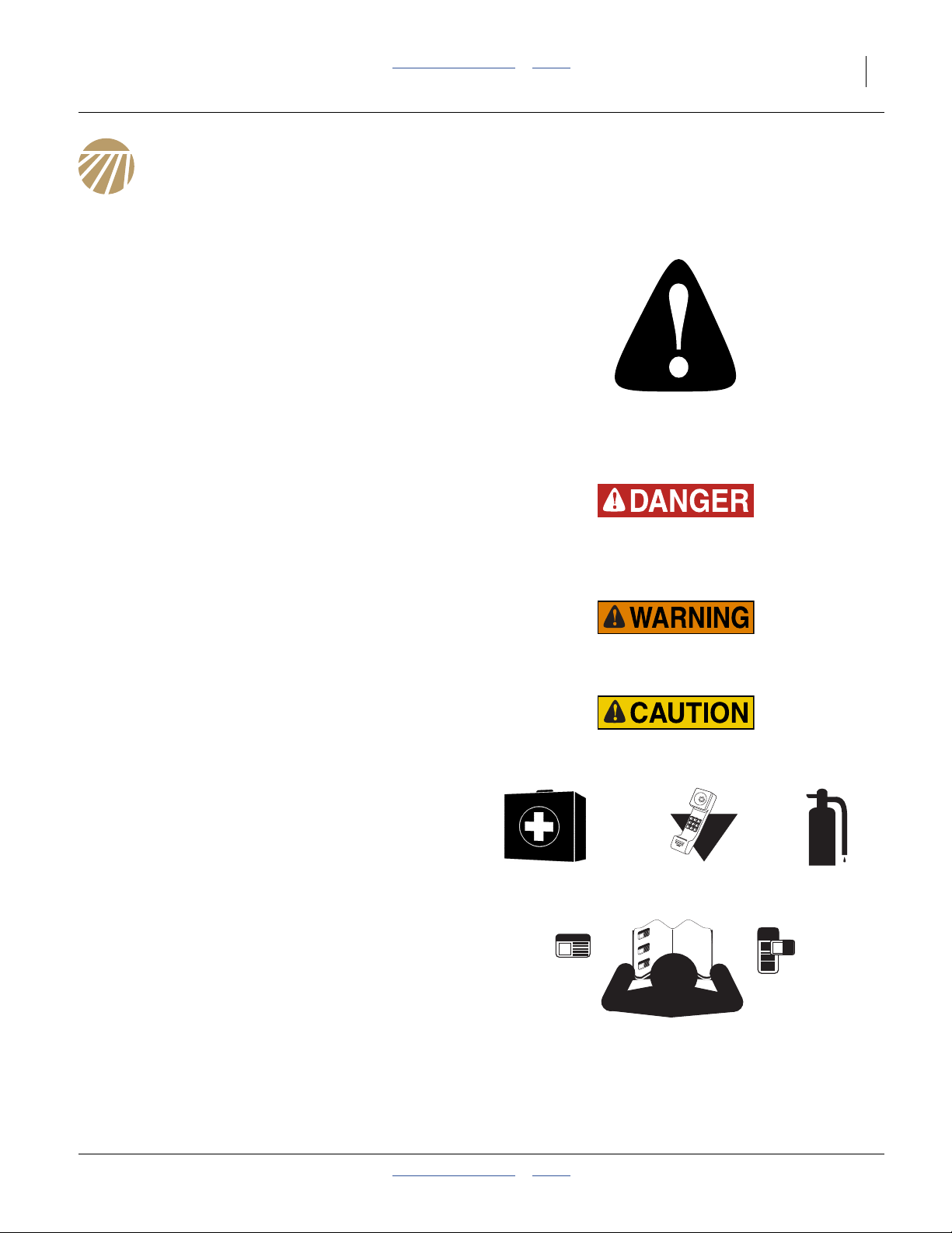
Look for Safety Symbol
The SAFETY ALERT SYMBOL indicates there is a
potential hazard to personal safety involved and extra
safety precaution must be taken. When you see this
symbol, be alert and carefully read the message that follows it. In addition to design and configuration of equipment, hazard control and accident prevention are
dependent upon the awareness, concern, prudence and
proper training of personnel involved in the operation,
transport, maintenance and storage of equipment.
Be Aware of Signal Words
Signal words designate a degree or level of hazard seriousness.
DANGER indicates an imminently hazardous situation
which, if not avoided, will result in death or serious injury.
This signal word is limited to the most extreme situations,
typically for machine components that, for functional purposes, cannot be guarded.
WARNING indicates a potentially hazardous situation
which, if not avoided, could result in death or serious
injury, and includes hazards that are exposed when
guards are removed. It may also be used to alert against
unsafe practices.
CAUTION indicates a potentially hazardous situation
which, if not avoided, may result in minor or moderate
injury. It may also be used to alert against unsafe practices.
Prepare for Emergencies
▲ Be prepared if a fire starts
▲ Keep a first aid kit and fire extinguisher handy.
▲ Keep emergency numbers for doctor, ambulance, hospital
and fire department near phone.
000
112
911
999
Be Familiar with Safety Decals
▲ Read and understand “Safety Decals” on page 5, thor-
oughly.
▲ Read all instructions noted on the decals.
▲ Keep decals clean. Replace damaged, faded and illegible
decals.
2013-10-29 Table of Contents Index 196-359M
Page 6

2 3N-4010F/3N-4010HDF/3N-4020F Table of Contents Index Great Plains Manufacturing, Inc.
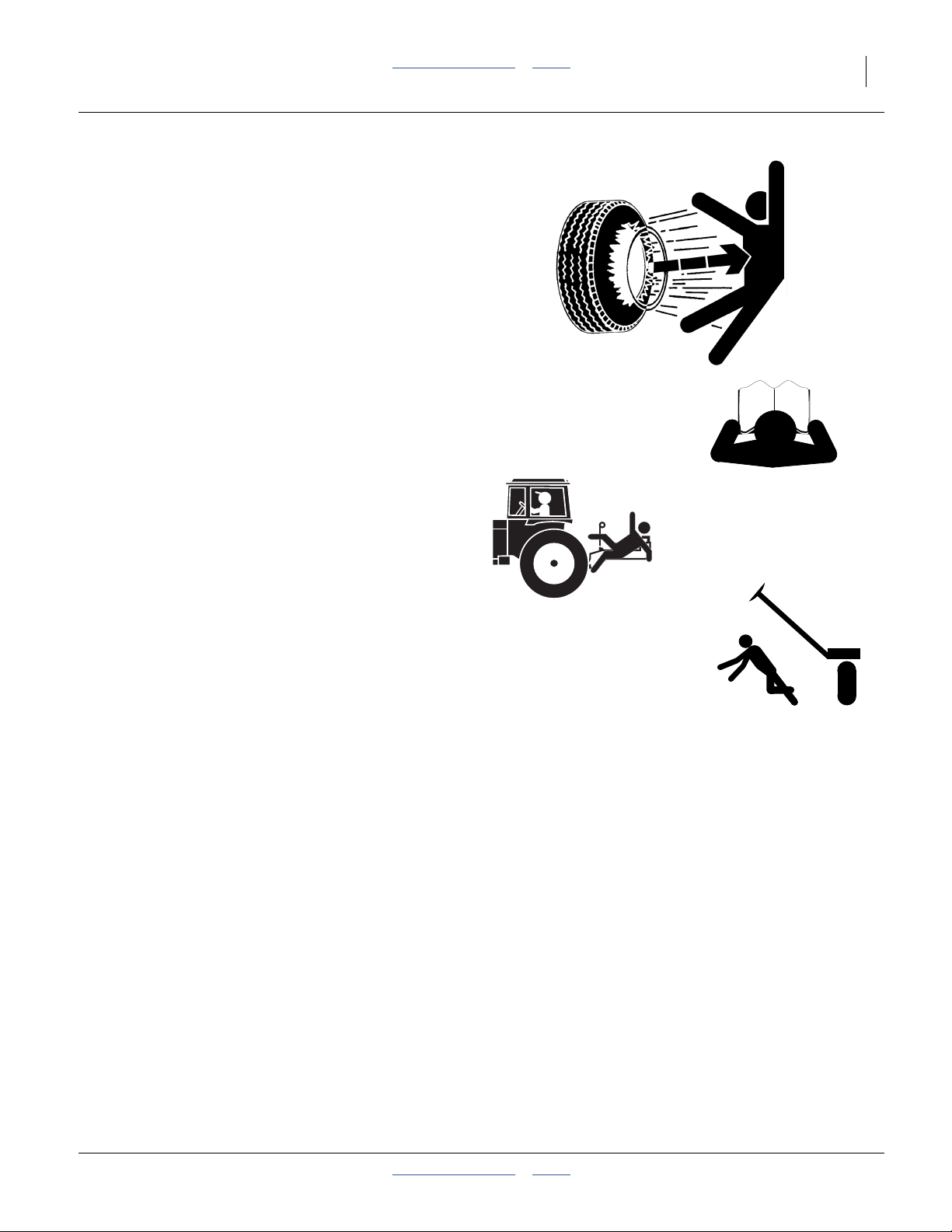
Wear Protective Equipment
▲ Wear protective clothing and equipment.
▲ Wear clothing and equipment appropriate for the job. Avoid
loose-fitting clothing.
▲ Because prolonged exposure to loud noise can cause hear-
ing impairment or hearing loss, wear suitable hearing protection such as earmuffs or earplugs.
▲ Because operating equipment safely requires your full
attention, avoid wearing entertainment headphones while
operating machinery.
Handle Chemicals Properly
Agricultural chemicals can be dangerous. Improper use
can seriously injure persons, animals, plants, soil and
property.
▲ Do not use liquid treatments with drill.
▲ Read and follow chemical manufacturer’s instructions.
▲ Wear protective clothing.
▲ Handle all chemicals with care.
▲ Avoid inhaling smoke from any type of chemical fire.
▲ Never drain, rinse or wash dispensers within 100 feet (30m)
of a freshwater source, nor at a car wash.
▲ Store or dispose of unused chemicals as specified by chemi-
cal manufacturer.
▲ Dispose of empty chemical containers properly. Laws gener-
ally require power rinsing or rinsing three times, followed by
perforation of the container to prevent re-use.
Avoid High Pressure Fluids
Escaping fluid under pressure can penetrate the skin,
causing serious injury.
▲ Avoid the hazard by relieving pressure before disconnecting
hydraulic lines.
▲ Use a piece of paper or cardboard, NOT BODY PARTS, to
check for suspected leaks.
▲ Wear protective gloves and safety glasses or goggles when
working with hydraulic systems.
▲ If an accident occurs, seek immediate medical attention
from a physician familiar with this type of injury.
196-359M Table of Contents Index 2013-10-29
Page 7
Great Plains Manufacturing, Inc. Table of Contents Index Important Safety Information 3
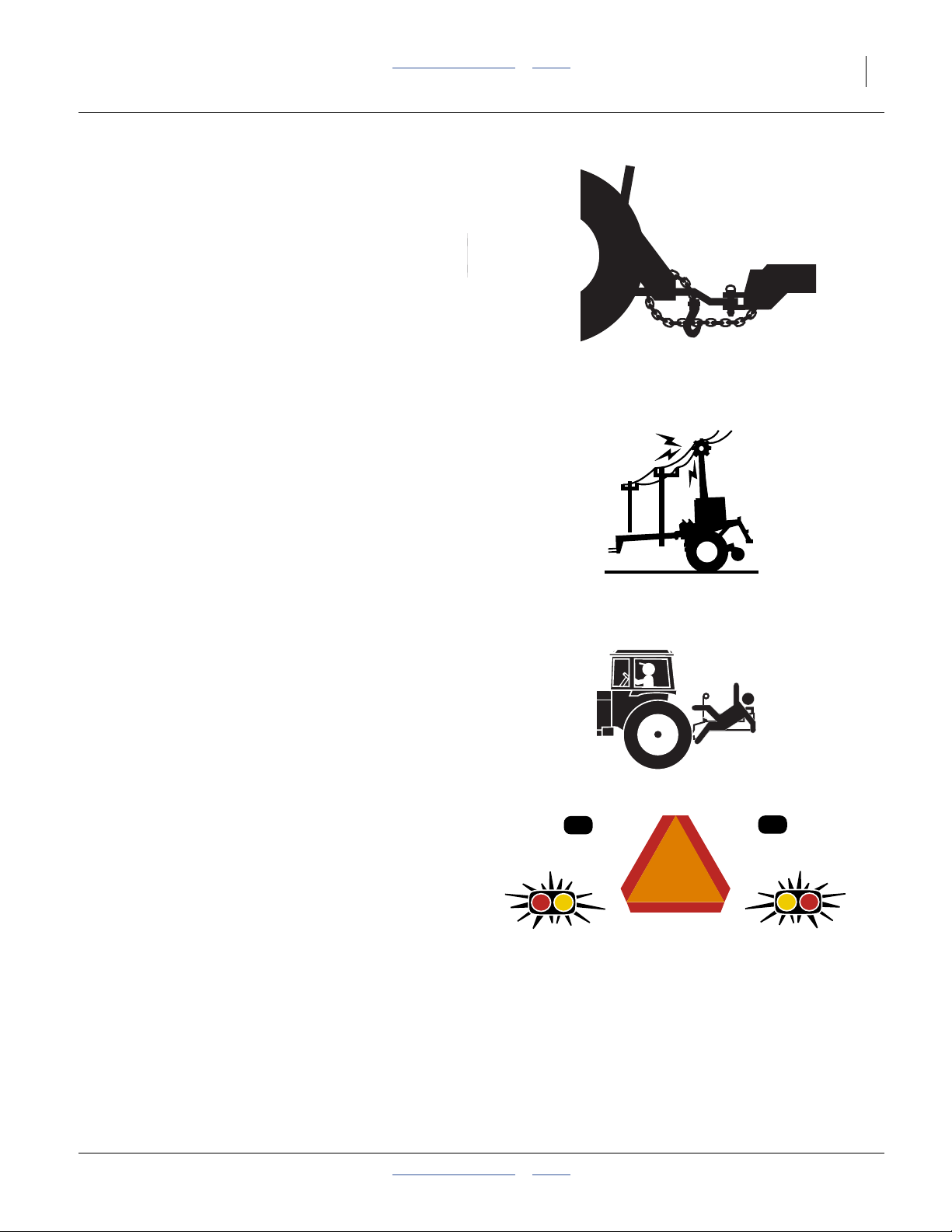
Use A Safety Chain
▲ Use a safety chain to help control drawn machinery should
it separate from tractor drawbar.
▲ Use a chain with a strength rating equal to or greater than
the gross weight of towed machinery.
▲ Attach chain to tractor drawbar support or other specified
anchor location. Allow only enough slack in chain to permit
turning.
▲ Replace chain if any links or end fittings are broken,
stretched or damaged.
▲ Do not use safety chain for towing.
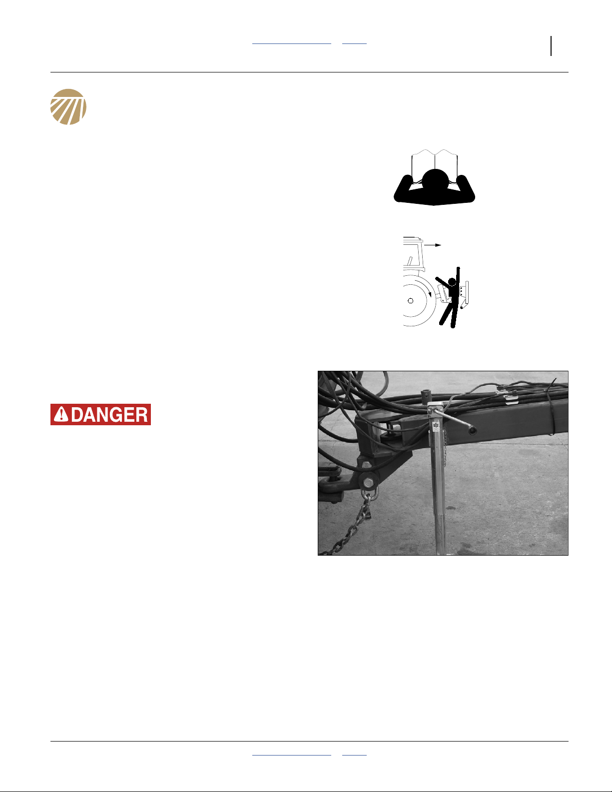
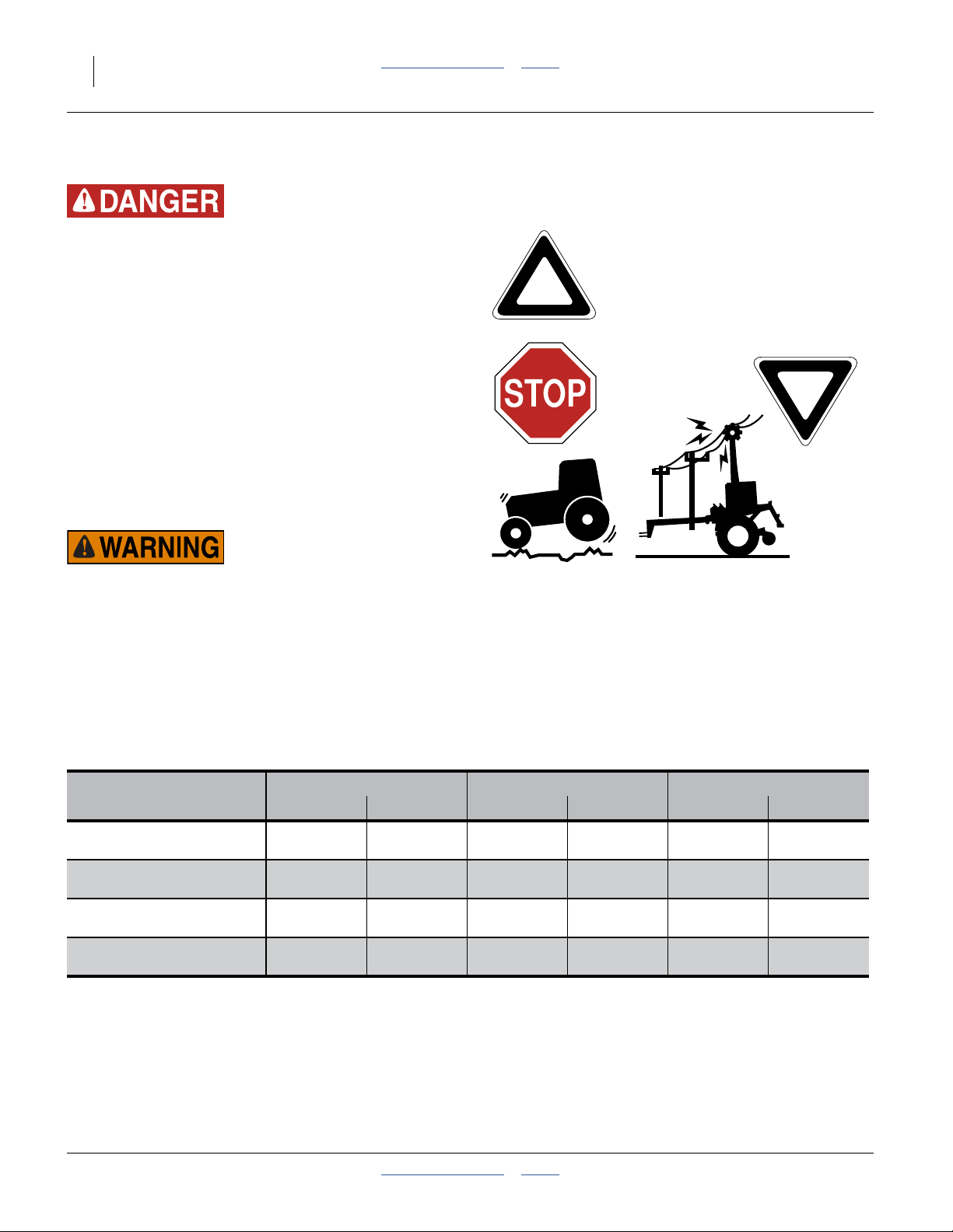
Check for Overhead Lines
Drill markers contacting overhead electrical lines can
introduce lethal voltage levels on drill and tractor frames.
A person touching almost any metal part can complete
the circuit to ground, resulting in serious injury or death.
At higher voltages, electrocution can occur without direct
contact.
▲ Avoid overhead lines during seed loading and marker oper-
ations.
Keep Riders Off Machinery
Riders obstruct the operator’s view. Riders could be
struck by foreign objects or thrown from the machine.
▲ Never allow children to operate equipment.
▲ Keep all bystanders away from machine when fold-
ing/unfolding, raising/lowering markers, raising/lowering
openers, and transporting.
Use Safety Lights and Devices
Slow-moving tractors and towed implements can create
a hazard when driven on public roads. They are difficult
to see, especially at night.
▲ Use flashing warning lights and turn signals whenever driv-
ing on public roads.
▲ Use lights and devices provided with drill.
2013-10-29 Table of Contents Index 196-359M
Page 8
4 3N-4010F/3N-4010HDF/3N-4020F Table of Contents Index Great Plains Manufacturing, Inc.
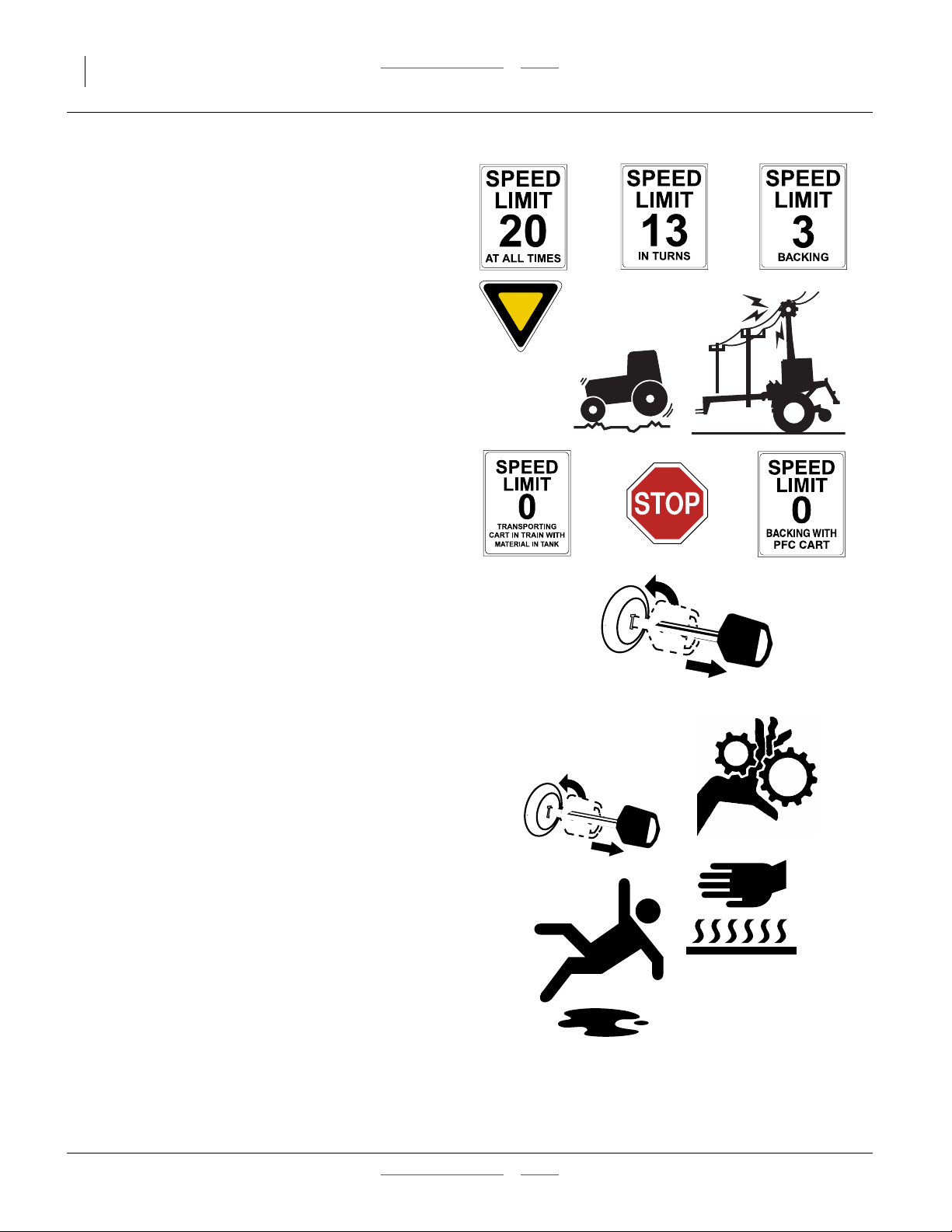
Transport Machinery Safely
Maximum transport speed for drill is 20 mph (32 kph).
Some rough terrains require a slower speed. Sudden
braking can cause a towed load to swerve and upset.
▲ Drill must be raised, locked-up, folded and locked for trans-
port.
▲ Do not exceed 20 mph (32 kph). Never travel at a speed
which does not allow adequate control of steering and stopping. Reduce speed if towed load is not equipped with
brakes.
▲ Comply with national, regional and local laws.
▲ Do not tow a load that weighs more than 1.5x the weight of
the tractor. See page 26 for details.
▲ Carry reflectors or flags to mark drill in case of breakdown
on the road.
▲ Keep clear of overhead power lines and other obstructions
when transporting. Refer to transport dimensions under
“Specifications and Capacities” on page 125.
Shutdown and Storage
▲ Clean out and safely store or dispose of residual chemicals.
▲ Secure drill using blocks and transport locks. Lower open-
ers if not locked up.
▲ Store in an area where children normally do not play.
Practice Safe Maintenance
▲ Understand procedure before doing work. Use proper tools
and equipment. Refer to this manual on the Parts manual
for additional information.
▲ Work in a clean, dry area.
▲ Put tractor in park, turn off engine, and remove key before
performing maintenance.
▲ Make sure all moving parts have stopped and all system
pressure is relieved.
▲ Disconnect battery ground cable (-) before servicing or
adjusting electrical systems or before welding on drill.
▲ Inspect all parts. Make sure parts are in good condition and
installed properly.
▲ Remove buildup of grease, oil or debris.
OFF
OFF
▲ Remove all tools and unused parts from drill before opera-
tion.
196-359M Table of Contents Index 2013-10-29
Page 9
Great Plains Manufacturing, Inc. Table of Contents Index Important Safety Information 5
Tire Safety
Tire changing can be dangerous and should be performed by trained personnel using correct tools and
equipment.
▲ When inflating tires, use a clip-on chuck and extension hose
long enough for you to stand to one side–not in front of or
over tire assembly. Use a safety cage if available.
▲ When removing and installing wheels, use wheel-handling
equipment adequate for weight involved.
Safety At All Times
Thoroughly read and understand the instructions in this
manual before operation. Read all instructions noted on
the safety decals.
▲ Be familiar with all drill functions.
▲ Operate machinery from the driver’s seat only.
▲ Do not leave drill unattended with tractor engine running.
▲ Do not dismount a moving tractor. Dismounting a moving
tractor could cause serious injury or death.
▲ Do not stand between the tractor and drill during hitching.
▲ Keep hands, feet and clothing away from power-driven
parts.
▲ Wear snug-fitting clothing to avoid entanglement with mov-
ing parts.
Safety Decals
Safety Reflectors and Decals
Your drill comes equipped with all lights, safety reflectors
and decals in place. They were designed to help you
safely operate your drill.
▲ Read and follow decal directions.
▲ Keep lights in operating condition.
▲ Keep all safety decals clean and legible.
▲ Replace all damaged or missing decals. Order new decals
from your Great Plains dealer. Refer to this section for
proper decal placement.
▲ When ordering new parts or components, also request cor-
responding safety decals.
To install new decals:
2013-10-29 Table of Contents Index 196-359M
Page 10
6 3N-4010F/3N-4010HDF/3N-4020F Table of Contents Index Great Plains Manufacturing, Inc.
1. Clean the area on which the decal is to be placed.
2. Peel backing from decal. Press firmly on surface,
being careful not to cause air bubbles under decal.
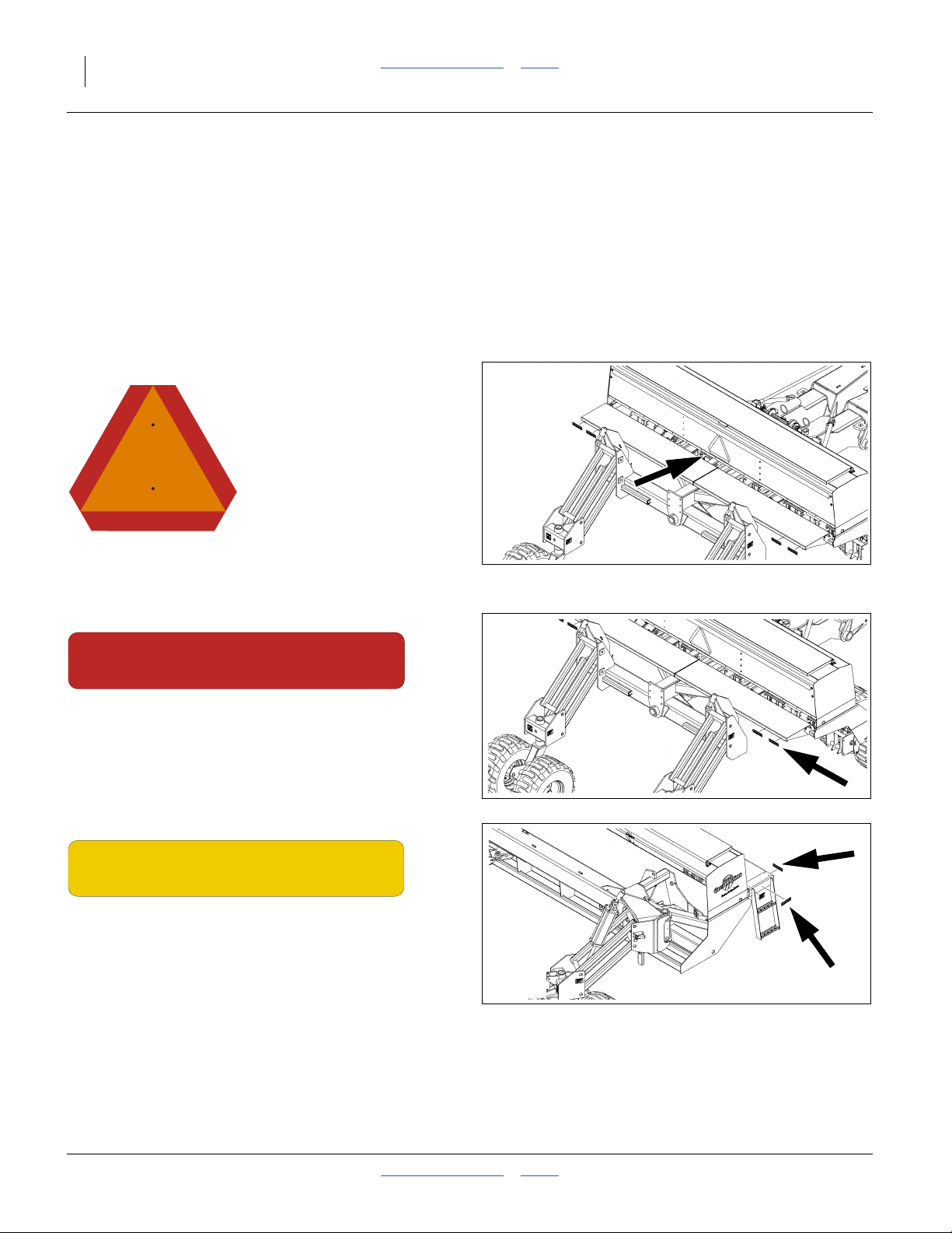
818-055C
Slow Moving Vehicle Reflector
Center rear of center box;
1 total
838-266C
Red Reflectors
On the outside edge of center walkboard each end;
4 total
838-265C
Amber Reflectors
On the ends and back edges of walkboards on both
wings;
2 total
196-359M Table of Contents Index 2013-10-29
Page 11
Great Plains Manufacturing, Inc. Table of Contents Index Important Safety Information 7
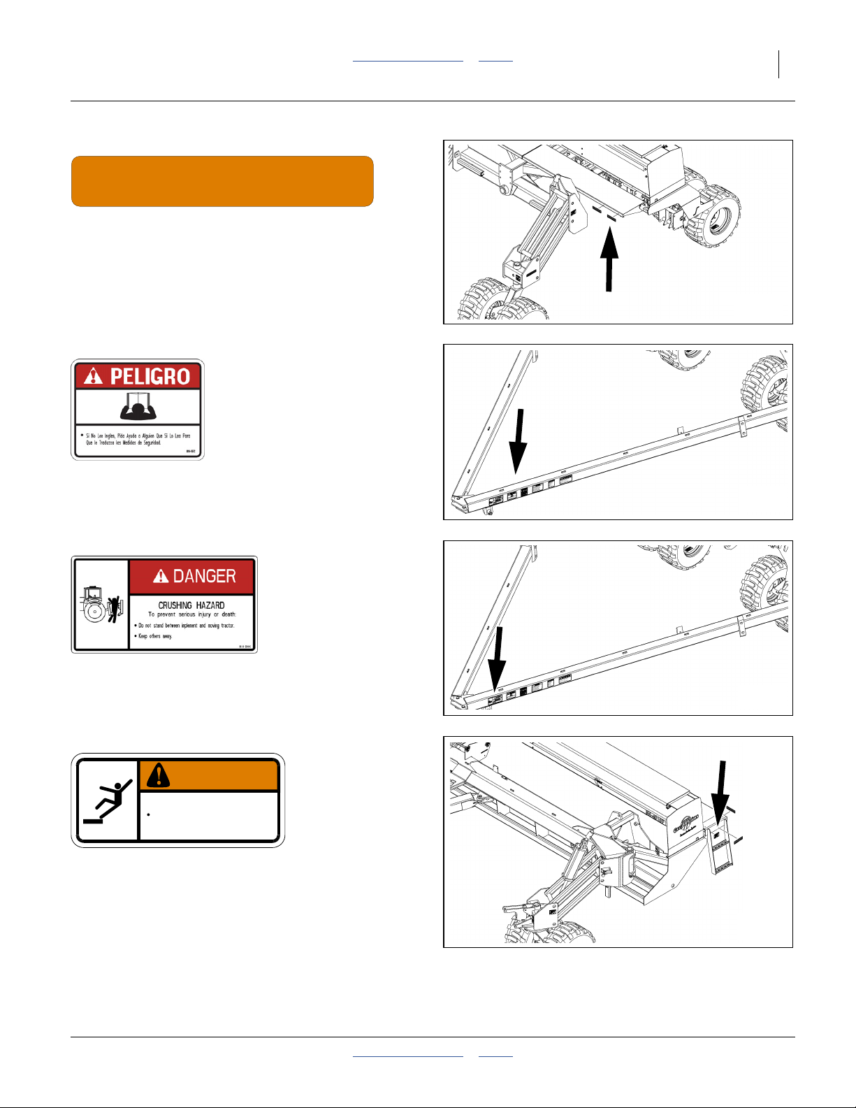
838-267C
Daytime Reflectors
On the outside edge of center walkboard each end;
2 total
20301
818-557C
Danger: Cannot Read English
On tongue near hitch;
1 total
818-590C
Danger: Crushing Hazard
On tongue near hitch;
1 total
838-102C
WARNING
To avoid serious injury or death:
Watch your step when climbing ladder or
walking on walkboard.
Danger: Falling Hazard
Outside edge of wing walkboards;
2 total
838-102C
20301
20301
20301
2013-10-29 Table of Contents Index 196-359M
Page 12
8 3N-4010F/3N-4010HDF/3N-4020F Table of Contents Index Great Plains Manufacturing, Inc.
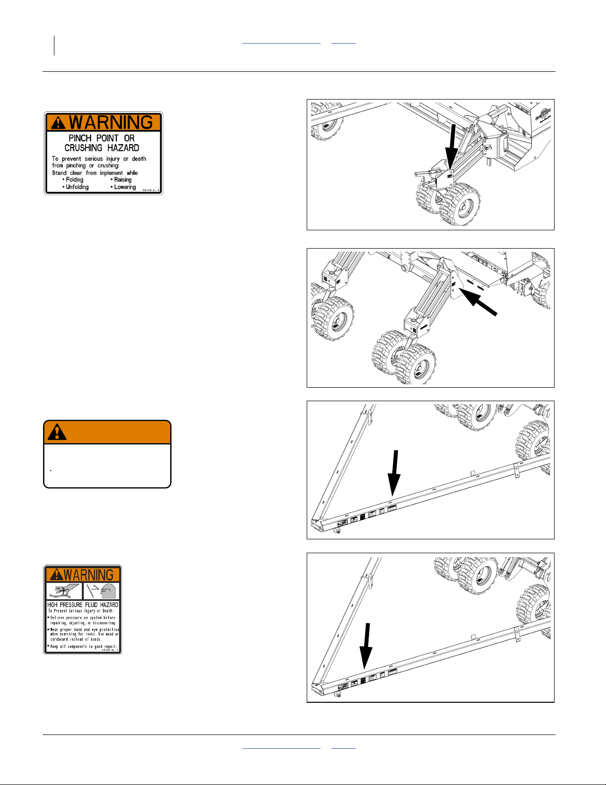
818-045C
Warning: Pinch/Crush
On transport wheel assembly;
4 total
20301
818-188C
WARNING
EXCESSIVE SPEED HAZARD
To Prevent Serious Injury or Death:
Do Not exceed 20 mph maximum transport
speed. Loss of vehicle control and/or machine
can result.
Warning: Speed Hazard
On tongue near hitch;
1 total
818-339C
818-188C Rev. C
20301
20301
Warning: High Pressure Fluid Hazard
On tongue near hitch;
1 total
196-359M Table of Contents Index 2013-10-29
20301
Page 13
Great Plains Manufacturing, Inc. Table of Contents Index Important Safety Information 9
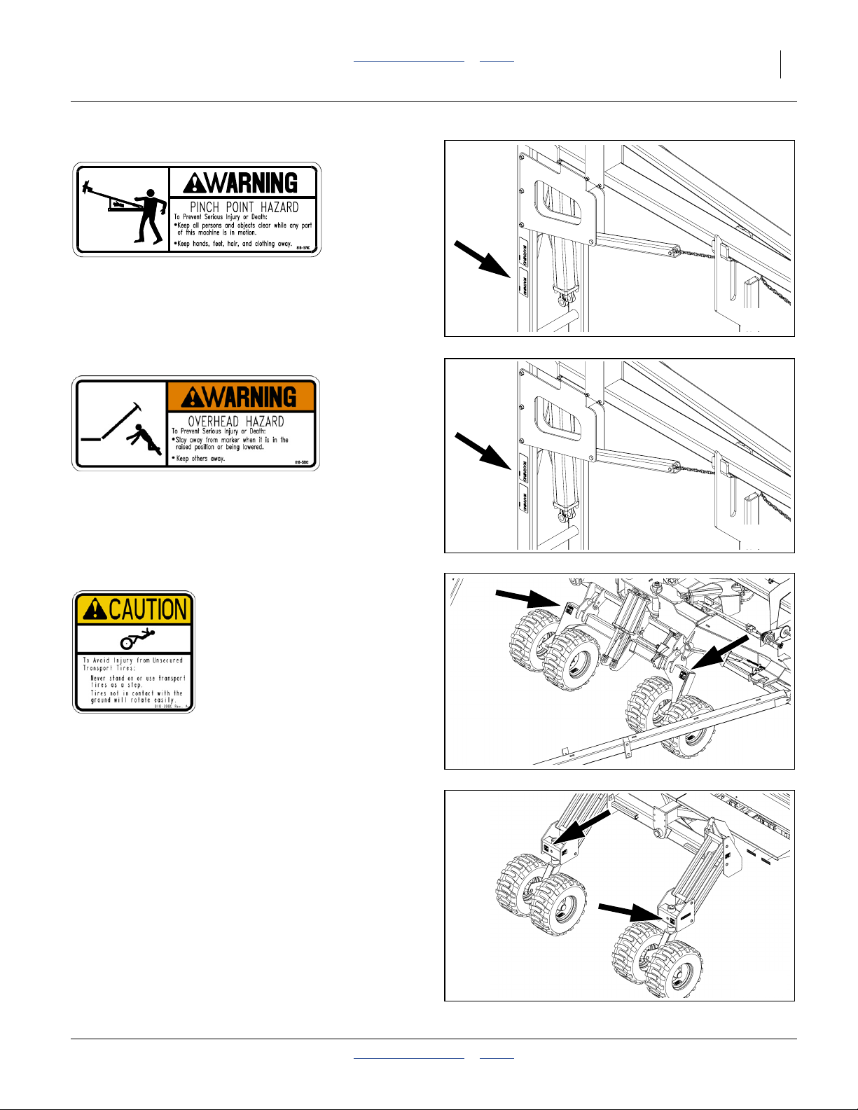
818-579C (Option)
Warning: Pinch Point
On marker, two with single, four with dual marker option;
2 or 4 total
20306l
818-580C (Option)
Warning: Overhead Hazard
On marker, two with single, four with dual marker option;
2 or 4 total
818-398C
Caution: Tires Not A Step
Above all sets of tires;
6 total
20306
20301
20301
2013-10-29 Table of Contents Index 196-359M
Page 14
10 3N-4010F/3N-4010HDF/3N-4020F Table of Contents Index Great Plains Manufacturing, Inc.
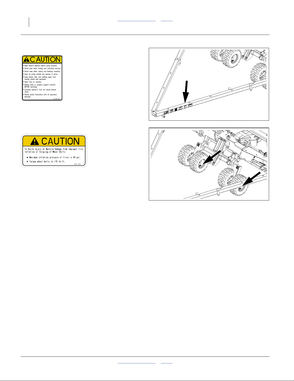
818-587C
Caution: General
On tongue near hitch;
1 total
20301
838-426C
Caution: Pressure/Torque
On the rim of each tire;
12 total
20301
196-359M Table of Contents Index 2013-10-29
Page 15
Great Plains Manufacturing, Inc. Table of Contents Index 11
Introduction
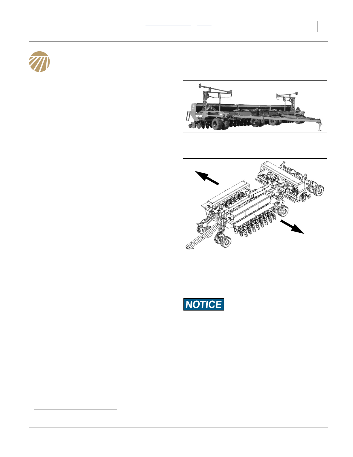
Great Plains welcomes you to its growing family of new
product owners. Your 3-Section 40-Foot No-Till Drill has
been designed with care and built by skilled workers
using quality materials. Proper setup, maintenance, and
safe operating practices will help you get years of satisfactory use.
Document Family
196-359M Operator Manuala (this document)
196-359P Parts Manual
Description of Unit
The 3N-4010F, 3N-4010HDF and 3N-4020F are pull-type
seeding implements outfitted with hydraulic drive metering and no-till coulters for use in no-till or minimum-till
conditions.
The 3N-4010F has 10 Series, parallel-arm openers.
The 3N-4010HDF has 10HD (Heavy Duty) openers.
The 3N-4020F has 20 Series, side-depth-control openers. All models fold for transport.
Models Covered by this Manual
10 Series Openers:
3N-4010F-4810 48 Rows, 10 inch/25cm
3N-4010F-6475 64 Rows, 7.5 inch/19cm
10HD (Heavy Duty) Series Openers:
3N4010HDF-481048 Rows, 10 inch/25cm
3N4010HDF-647564 Rows, 10 inch/19cm
20 Series Openers:
3N-4020F-4810 48 Rows, 10 inch/25cm
3N-4020F-6475 64 Rows, 7.5 inch/19cm
Intended Usage
Use the drill to seed production-agriculture crops only.
Do not modify the drill for use with attachments other
than Great Plains options and accessories specified or
recommended for use with the drill.
Definitions
The following terms are used throughout this manual.
Right-hand and left-hand as used in this manual are
determined by facing the direction the machine will travel
while in use unless otherwise stated.
Figure 1
3N-40 Drill
28229
R
L
Figure 2
Left/Right Notation
Paragraphs in this format present a crucial point of information
related to the current topic.
Read and follow the directions to:
- remain safe,
- avoid serious damage to equipment and
- ensure desired field results.
Note: Paragraphs in this format provide useful informa-
tion related to the current topic.
20476
a. This manual also covers seeding rate. There is no separate Seed Rate manual.
2013-10-29 Table of Contents Index 196-359M
Page 16
12 3N-4010F/3N-4010HDF/3N-4020F Table of Contents Index Great Plains Manufacturing, Inc.
Using This Manual
This manual will familiarize you with safety, assembly,
operation, adjustments, troubleshooting, and maintenance. Read this manual and follow the recommendations to help ensure safe and efficient operation.
The information in this manual is current at printing.
Some parts may change to assure top performance.
Owner Assistance
If you need customer service or repair parts, contact a
Great Plains dealer. They have trained personnel, repair
parts and equipment specially designed for Great Plains
products.
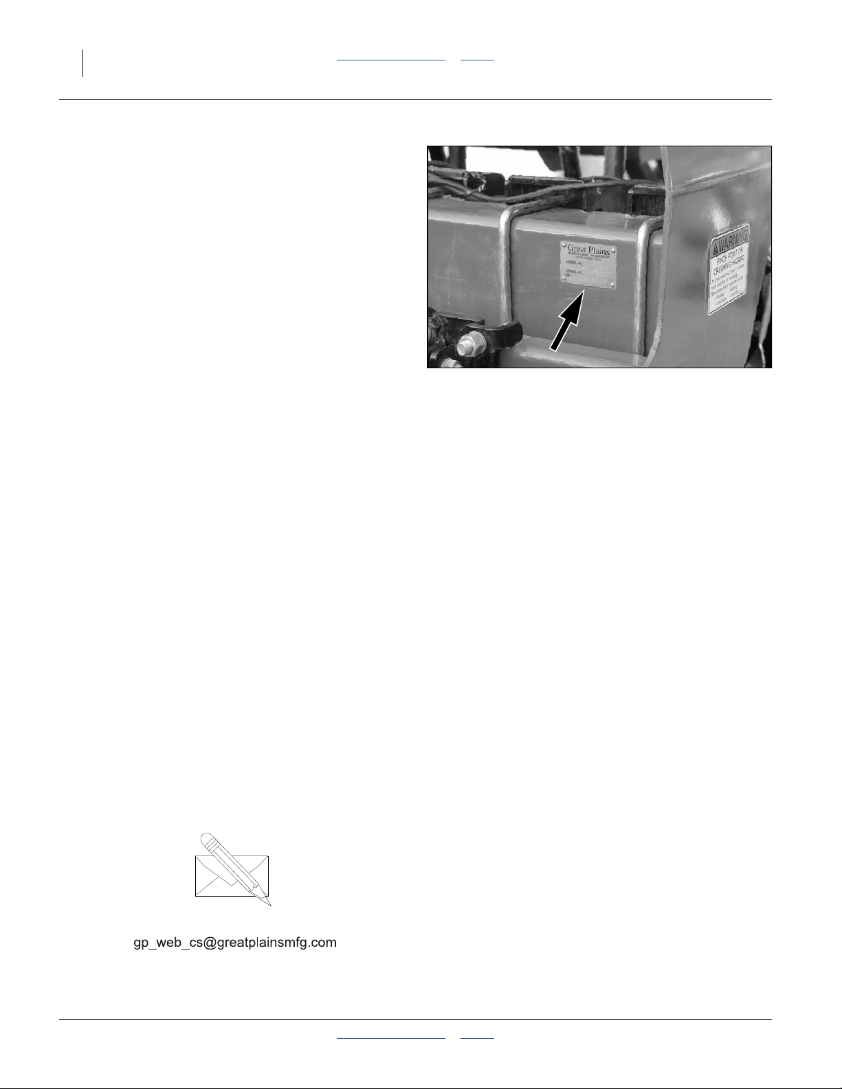
Refer to Figure 3
Your machine’s parts were specially designed and
should only be replaced with Great Plains parts. Always
use the serial and model number when ordering parts
from your Great Plains dealer. The serial number plate is
located on the front of the left hand side of the center
section as shown.
Record your drill model and serial number here for quick
reference:
Model Number:__________________________
Serial Number: __________________________
Your Great Plains dealer wants you to be satisfied with
your new machine. If you do not understand any part of
this manual or are not satisfied with the service received,
please take the following actions.
1. Discuss the matter with your dealership service
manager. Make sure they are aware of any problems
so they can assist you.
2. If you are still unsatisfied, seek out the owner or general manager of the dealership.
For further assistance write to:
Figure 3
Serial Number Plate
20270
Product Support
Great Plains Mfg. Inc., Service Department
PO Box 5060
Salina, KS 67402-5060
785-823-3276
196-359M Table of Contents Index 2013-10-29
Page 17
Great Plains Manufacturing, Inc. Table of Contents Index 13
Preparation and Setup
This section will help you prepare your tractor and drill for
use. Before using the drill in the field, you must hitch the
drill to a suitable tractor and level the drill.
Pre-Setup Checklist
1. Read and understand “Important Safety Information” on page 1.
2. Check that all working parts are moving freely, bolts
are tight, and cotter pins are spread.
3. Check that all grease fittings are in place and lubricated. See “Lubrication” on page 114.
4. Check that all safety decals and reflectors are correctly located and legible. Replace if damaged. See
“Safety Decals” on page 5.
5. Inflate tires to pressure recommended and tighten
wheel bolts as specified. “Appendix” on page 125.
Hitching
There are three hitch options (see page 119). Check that
the tractor and drill are compatible before hitching.
Crushing Hazard: You may be severely injured or killed by
being crushed between the tractor and drill. Do not stand or
place any part of your body between machines being hitched.
Stop tractor engine and set park brake before installing hitch
pins.
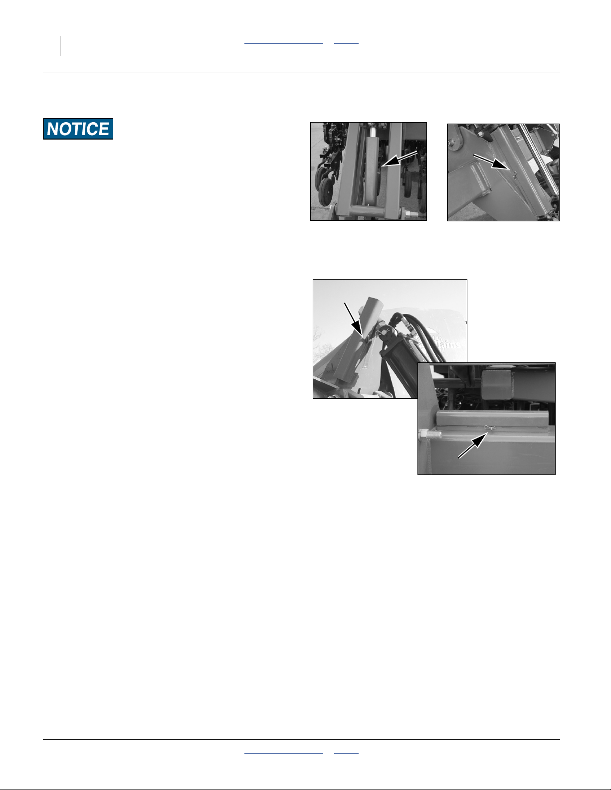
Refer to Figure 4
1. Use drill parking jack to raise or lower tongue as
needed. Hitch drill to tractor using a hitch pin of ade-
quate strength - minimum diameter 11⁄2in (38mm).
2. Install a retaining clip on the hitch pin to prevent it
from working up.
3. Securely attach drill safety chain to tractor drawbar.
4. Lower tongue onto tractor drawbar with jack.
Remove jack and store on tongue.
Make Electrical Connections
Make sure tractor is shut down with accessory power off
before making connections. Connections include:
5. Lighting
6. Veris controller harness
7. Electric Clutch (Point Row) harness (2 connectors)
8. Shaft monitor (option)
Figure 4
Hitching Tractor to Drill
20273
2013-10-29 Table of Contents Index 196-359M
Page 18
14 3N-4010F/3N-4010HDF/3N-4020F Table of Contents Index Great Plains Manufacturing, Inc.
Make Hydraulic Connections
High Pressure Fluid Hazard:
Only trained personnel should work on system hydraulics!
Escaping fluid under pressure can penetrate skin, causing serious injury. Avoid the hazard by relieving pressure before disconnecting hydraulic lines. Use a piece of paper or cardboard,
NOT BODY PARTS, to check for leaks. Wear protective gloves
and safety glasses or goggles when working with hydraulic
systems. If an accident occurs, seek immediate medical attention from a physician familiar with this type of injury.
The drive is compatible only with closed center, PC (pressure
compensated) closed or LS (load sensing) hydraulic systems.
Do not use an open center system.
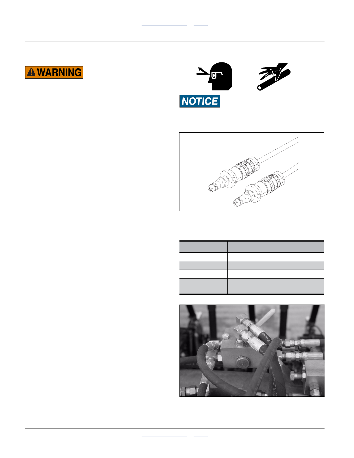
Hydraulic Circuit Connections
Refer to Figure 5
Great Plains hydraulic hoses are color coded handle
grips to help you hookup hoses to your tractor outlets.
Hoses that go to the same remote valve are marked with
the same color.
To distinguish hoses on the same hydraulic circuit, refer
to the symbol molded into the handle grip. Hoses with an
extended-cylinder symbol feed cylinder base ends.
Hoses with a retracted-cylinder symbol feed cylinder rod
ends.
The drill has three or four hydraulic circuits. The standard
circuits power drive/locks, lift, and fold. If markers are
present, they require a fourth circuit (or an additional
selector valve sharing the fold circuit).
If the tractor has only one circuit rated for continuous
flow, reserve it for the hydraulic drive.
1. Shut down tractor hydraulics.
2. Connect the hydraulic drive circuit.
3. Connect remaining circuits.
4. Check hose routing to ensure adequate slack for link
arm movement, and clearance from pinching or
abrading drill components.
Refer to Figure 6
Figure 5
Color Coded Hose Handles
Current Style Color Coded Hose Handles
Hose Color Hydraulic Function
Gray Fold
Blue Lift
Green Marker Cylinders (Option)
Yellow
Hydraulic Drive and
Wing and Swivel Locks
31733
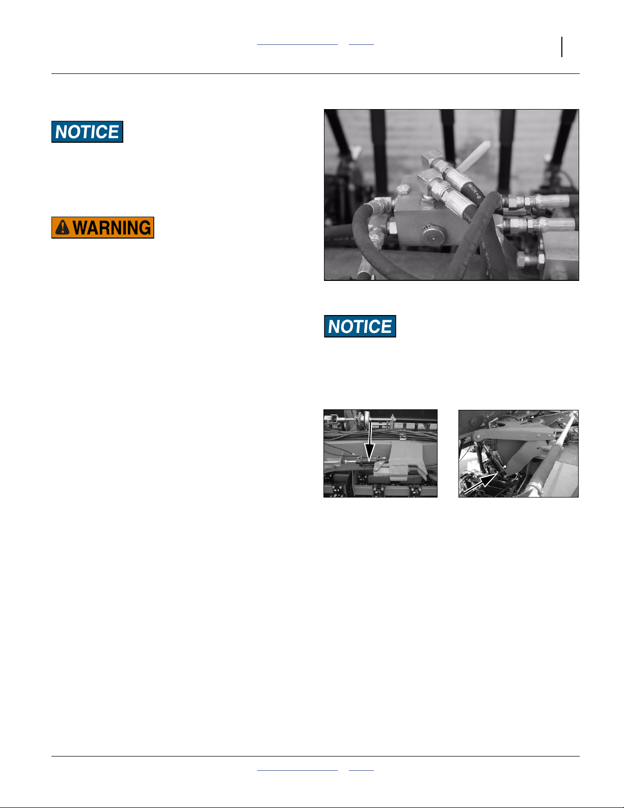
5. If the drill is to be unfolded, set the selector valve to
Locks (handle to drill center). Valve is located near
rear end of left tongue tube.
Figure 6
Hitching: Drive/Lock Selector Valve
196-359M Table of Contents Index 2013-10-29
Page 19

Great Plains Manufacturing, Inc. Table of Contents Index Preparation and Setup 15
Older Style Hoses with Color Ties
Refer to Figure 7
To distinguish hoses on the same hydraulic circuit, refer
to plastic hose label. The hose under an extended-cylinder symbol feeds a cylinder base end. The hose under a
retracted-cylinder symbol feeds a cylinder rod end.
.
The drive is compatible only with closed center, PC (pressure
compensated) closed or LS (load sensing) hydraulic systems.
Do not use an open center system.
Hose Color Hydraulic Function
White Fold
Blue Lift
Orange Marker Cylinders (Option)
Yellow
Hydraulic Drive and
Wing and Swivel Locks
Figure 7
Plastic Hose Label
817-348c
17641
2013-10-29 Table of Contents Index 196-359M
Page 20
16 3N-4010F/3N-4010HDF/3N-4020F Table of Contents Index Great Plains Manufacturing, Inc.
Initial Setup
The following items need to be done for first use, and
some need to be re-done if the tractor changes.
Initial Tractor Setup
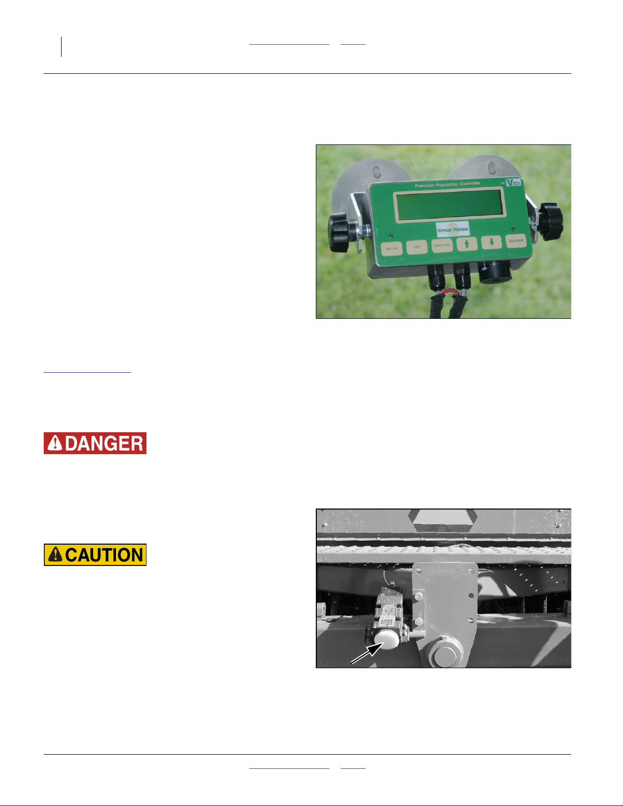
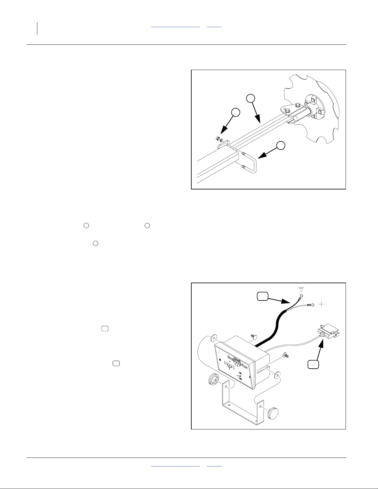
Veris Controller
The standard Veris hydraulic drive, controller module and
DICKEY-john radar are factory-installed on the drill. The
Veris console needs to be installed in the tractor prior to
first use. It includes suction cup feet that can support the
console on glazing for extended periods.
Route the power lead to a +12Vdc source. Route the
harness to the hitch, allowing enough slack for hitch
movement and any tractor articulation.
Refer to Figure 8
Mount the console where the display is visible during
planting, but does not obstruct vision of tractor or drill
systems, and does not impair safe highway transport.
Installation instructions are found in an included Veris
manual. Additional copies are available at:
www.veristech.com
Expanded operating information from that manual is found in this manual, starting on page 35.
Once the console is installed, you can enter the initial
setup data by stepping through the calibration sequence
but not actually operating the motor. See page 39.
Figure 8
Veris Controller
28326
Moving Chain Hazard
Pinch/Crush Hazard
Shaft Entanglement Hazard:
Be careful when working around drill while tractor is running.
Any movement detected by the radar gun (Figure 9) can activate the Veris hydraulic drive causing motion of chains,
sprockets, shafts and seed meters.
Vision Hazard:
The DICKEY-john RVS II radar speed sensor is an intentional
radiator of RF energy. Although its radiated energy level is far
below the limits set by EN 61010-1: 1993\A2: 1995 - Chapter
12.4, it is advisable not to look directly into the face of the unit.
The radar must radiate toward the ground and at least 20 cm
(8 inches) away from a human during use to comply with the
RF human exposure limits per FCC 47 CFR Sec. 2.1091.
DO NOT mount or use the radar in a manner inconsistent with
its defined use.
Figure 9
DICKEY-john Radar
20310
196-359M Table of Contents Index 2013-10-29
Page 21
Great Plains Manufacturing, Inc. Table of Contents Index Preparation and Setup 17
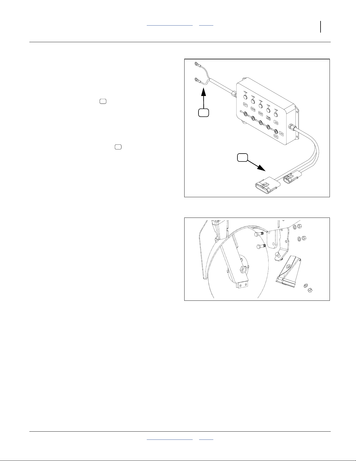
Point Row Switch Module
Refer to Figure 10
6. Choose a tractor cab location where the module
does not obstruct vision, and the switches can be
safely operated during planting passes.
7. Route the power leads to a source of +12 Vdc
power capable of supplying 12.6A.
Color code is red+, black-.
Direct battery connection is acceptable; the controller module has its own master switch and fuse.
8. Use a tie to secure the power lead.
9. Route the controller harness to the tractor hitch.
Use ties to secure the hitch lead.
P
H
Drill Setup Checks
Hydraulic Bleed
Bleeding the hydraulic system is not a routine daily setup
item. If the system has not been charged since delivery,
or any hydraulic work has been done (such as installing
markers), see “Bleeding Hydraulics” on page 105.
Drill Level
Drill sections are aligned and leveled at the factory, and
re-checked during dealer pre-delivery. Level normally
does not require routine adjustment before use. Great
Plains does recommend checking it once prior to first
field use. See “Level Frame Side to Side” on page 102.
Drill Option Setup
Even if factory- or dealer-installed, some optional items
may need checking or adjustment prior to first field use.
Install any that were not pre-installed.
Scrapers (Option)
If scrapers were ordered, and not dealer-installed, install
them now per the instructions in one of the following
manuals, which are available on the Great Plains website
if not ordered or included:
Kit: Manual
122-259K 122-262M (ordered separately)
198-960A 198-961M (included in kit)
P
H
Figure 10: 833-294C
Point Row Switch Module
Figure 11: 122-259K
10 & 20 Series Inside Scraper
28240
20162
2013-10-29 Table of Contents Index 196-359M
Page 22
18 3N-4010F/3N-4010HDF/3N-4020F Table of Contents Index Great Plains Manufacturing, Inc.
Marker Setup (Option)
If markers are not installed, install them now per the
instructions included with the markers.
Once installed, verify that they have been correctly bled
(See “Bleeding Markers” on page 107).
Set initial marker extension - the distance to the mark on
each side from the outside row unit on that side.
1. Move the hitched drill to a typical flat field.
2. Extend a marker on one side (see page 33). Pull forward a few feet or a meter or so to leave a mark.
3. Measure from the centerline of the outside row unit
(whether that row unit is to be used or not) to the
mark, along a line parallel to the wing.
Refer to Figure 175 through Figure 180 on pages 127 and 129
4. Check the measurement against the value recommended by Great Plains.
Refer to Figure 12
3
1
2
Figure 12
Adjusting Marker Extension
18878
If the marker extensions need adjustment:
5. Loosen the nuts securing the U-bolt at the
outer marker section.
6. Slide the inner tube in or out, and re-secure nuts.
See page 69 for further marker adjustments. Re-check
marker extension when changing disk angle, or when
inverting the disk, as both adjustments change the position of the centerline of the mark.
Shaft Monitor (Option)
1. Choose a tractor cab location where the module
does not obstruct vision, and the shaft indicators can
be easily seen if an alert sounds.
Refer to Figure 13
2. Route the power leads to a source of +12 Vdc
power.
Color code is red+, black-.
3. Use a tie to secure the power lead.
4. Route the monitor harness to the tractor hitch.
Use ties to secure the hitch lead.
For operation, see:
“Shaft Monitor Operation (Option)” on page 33.
For ordering information, see:
“Shaft Monitor” on page 121.
1 2
3
P
H
P
H
Figure 13: 823-060C
Shaft Monitor
196-359M Table of Contents Index 2013-10-29
28241
Page 23
Great Plains Manufacturing, Inc. Table of Contents Index Preparation and Setup 19
Install Weight Brackets (Option)
If weight brackets were ordered, and were not
dealer-installed, install them now. Two kits (4 brackets)
are supported, accepting five standard 100 pound (45
kg) “suitcase” tractor weights each, for a maximum additional weight of 2000 pounds (907 kg). Weights are not
included with kits.
If only one weight kit is to be installed, use the “Outer”
position.
Once the brackets are installed, see “Frame Weight”on
page 68 for operating information.
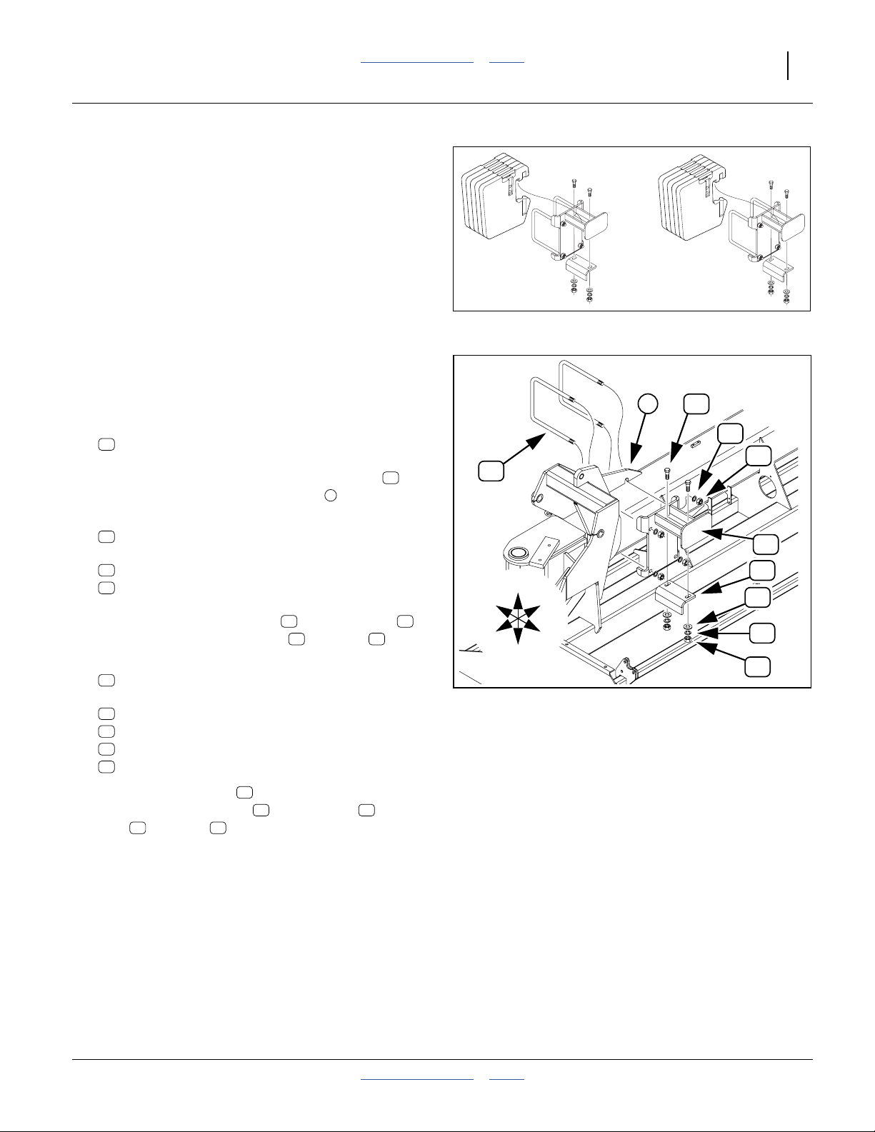
Install Outer Brackets
Start with the left wing.
Refer to Figure 15
1. Select two:
19
806-172C U-BOLT 3/4-10 X 10 1/32X11 1/2
Figure 14:
Weight Bracket Kit and Weights
1
13
18
27068
15
From the front of the wing, insert the U-Bolts
through the holes in the outside lug .
2. Select one:
11
196-291H 40P WEIGHT BRACKET WLDMNT
and four sets:
18
804-023C WASHER LOCK SPRING 3/4 PLT
15
803-027C NUT HEX 3/4-10 PLT
Mount the bracket weldment on the U-Bolts ,
and secure with lock washers and nuts .
3. Select one:
12
197-062D WEIGHT BRACKET ADJ LEG
and two sets:
13
802-057C HHCS 5/8-11X2 1/4 GR5
16
804-019C WASHER FLAT 5/8 USS PLT
17
804-022C WASHER LOCK SPRING 5/8 PLT
14
803-021C NUT HEX 5/8-11 PLT
11 19
1
18 15
19
19
F
L
U
D
R
B
Figure 15
Weight Bracket, Outer
11
12
16
17
14
20323
Orient the adjustment leg toward the outside (end of
wing), and secure with bolts , flat washers , lock
washers and nuts .
4. Repeat step 1 through step 3 for the right wing.
2013-10-29 Table of Contents Index 196-359M
17 14
12
13 16
Page 24
20 3N-4010F/3N-4010HDF/3N-4020F Table of Contents Index Great Plains Manufacturing, Inc.
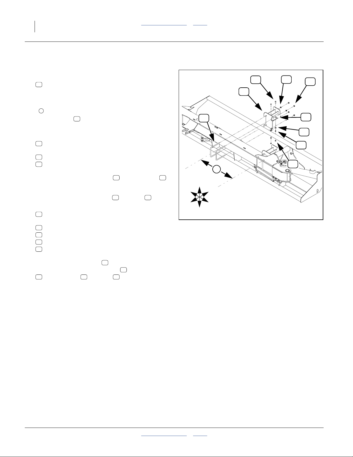
Install Mid-Wing Brackets
Refer to Figure 16
5. Select two:
19
806-172C U-BOLT 3/4-10 X 10 1/32X11 1/2
From the centerline of the inside U-Bolt installed at
step 1, measure toward drill center, approximately:
1
2
35
⁄
in (90cm)
2
Insert a U-bolt from drill front, under the hoses.
Insert the second U-Bolt 7
6. Select one:
11
196-291H 40P WEIGHT BRACKET WLDMNT
and four sets:
18
804-023C WASHER LOCK SPRING 3/4 PLT
15
803-027C NUT HEX 3/4-10 PLT
Position the bracket weldment on the U-Bolts ,
and adjust the placement as necessary to clear tube
weldments, web plates, grease banks, marker parts
and secure with lock washers and nuts .
7. Select one:
12
197-062D WEIGHT BRACKET ADJ LEG
and two sets:
13
802-057C HHCS 5/8-11X2 1/4 GR5
16
804-019C WASHER FLAT 5/8 USS PLT
17
804-022C WASHER LOCK SPRING 5/8 PLT
14
803-021C NUT HEX 5/8-11 PLT
19
1
⁄
in (19cm) further in.
2
11 19
18 15
R
F
U
D
19
13
11
2
B
L
Figure 16
Weight Bracket, Mid-Wing
18
15
12
16
17
14
28243
Orient the adjustment leg toward the inside (center of drill), and secure with bolts , flat washers
16 17 14
, lock washers and nuts .
8. Repeat step 5 through step 7 for the right wing.
12
13
196-359M Table of Contents Index 2013-10-29
Page 25
Great Plains Manufacturing, Inc. Table of Contents Index 21
Operating Instructions
This section covers general operating procedures. It
assumes that setup items have been completed.
Experience, machine familiarity and this information
leads to efficient operation and good working habits.
Always operate farm machinery with safety in mind.
Pre-Start Checklist
❑ Review “Important Safety Information” on page 1.
❑ Lubricate the drill as indicated under Lubrication,
“Maintenance and Lubrication” on page 100.
❑ Check the tires for proper inflation according to “Tire
Inflation Chart” on page 125.
❑ Check for worn or damaged parts and repair or
replace before going to the field.
❑ Check all nuts, bolts and screws. Tighten bolts as
specified on “Torque Values Chart” on page 126
❑ Check hydraulic hoses, fittings and cylinders for
leaks. Tighten, repair or replace before planting.
High Pressure Fluid Hazard: Escaping fluid under pressure
can penetrate skin, causing serious injury. Avoid the hazard by
relieving pressure before disconnecting hydraulic lines. Use a
piece of paper or cardboard, NOT BODY PARTS, to check for
leaks. Wear protective gloves and safety glasses or goggles
when working with hydraulic systems. If an accident occurs,
seek immediate medical attention from a physician familiar
with this type of injury.
Moving Chain Hazard
Pinch/Crush Hazard
Shaft Entanglement Hazard:
Be careful when working around drill while tractor is running.
Any movement detected by the radar gun (Figure 17) can activate the Veris hydraulic drive causing motion of chains,
sprockets, shafts and seed meters.
Vision Hazard:
The DICKEY-john RVS II radar speed sensor is an intentional
radiator of RF energy. Although its radiated energy level is far
below the limits set by EN 61010-1: 1993\A2: 1995 - Chapter
12.4, it is advisable not to look directly into the face of the unit.
The radar must radiate toward the ground and at least 20 cm
(8 inches) away from a human during use to comply with the
RF human exposure limits per FCC 47 CFR Sec. 2.1091.
DO NOT mount or use the radar in a manner inconsistent with
its defined use.
2013-10-29 Table of Contents Index 196-359M
Figure 17
DICKEY-john Radar
20310
Page 26
22 3N-4010F/3N-4010HDF/3N-4020F Table of Contents Index Great Plains Manufacturing, Inc.
Lift / Lower
Machine Damage Risk:
Lower only when the drill is unfolded. The drill must be raised
and locked up for folding and unfolding.
The drill has six rephasing lift cylinders that raise and
lower the opener frame.
Six (6) transport locks are provided, two for the rockshaft
(center forward) cylinders, and one each for the rear and
wing caster cylinders. These assure that the drill stays
raised during folding/unfolding, transport, storage, lubrication, maintenance and some setup/adjustment tasks.
Opener Operation Lowered
The “lowered” position of the opener frame is regulated
by an adjustable valve, factory set for 2in coulter depth.
See “Frame Height” on page 60 for adjustment.
Figure 18
Transport Locks Installed
20264
20266
Rephasing Lift System
Over a period of normal use the cylinders may get out of
phase. This causes some implement sections to run
higher than others when lowered. To minimize this, or
rephase the cylinders, make the following steps your normal raise sequence:
9. Raise drill completely and hold the hydraulic remote
lever on for several seconds until all cylinders are
fully extended. Do this every 3rd or 4th time you
raise the drill out of the ground.
10. When all cylinders are fully extended, momentarily
reverse the hydraulic remote lever to retract the sys-
1
tem
⁄
inch (13mm) to maintain levelness.
2
If implement is still not level after re-phasing, see “Bleed-
ing Lift Hydraulics” on page 105 and “Level Frame
Side to Side” on page 102.
Figure 19
Lock Channel Storage
20268
20269
196-359M Table of Contents Index 2013-10-29
Page 27
Great Plains Manufacturing, Inc. Table of Contents Index Operating Instructions 23
Folding the Drill
Machine Damage Risk:
Fold only when the drill is raised and locked up.
Fold the drill on level ground with the tractor in neutral.
If your drill has markers, be certain they are folded and
their control switches are off before folding.
Pinch Point and Crushing Hazard.
To prevent serious injury or death:
▲ Always use transport lift locks when drill is folded.
▲ Fold only if hydraulics are bled free of air and fully charged
with hydraulic oil.
▲ Stay away from frame sections when they are being raised
or lowered.
▲ Keep away and keep others away when folding drill.
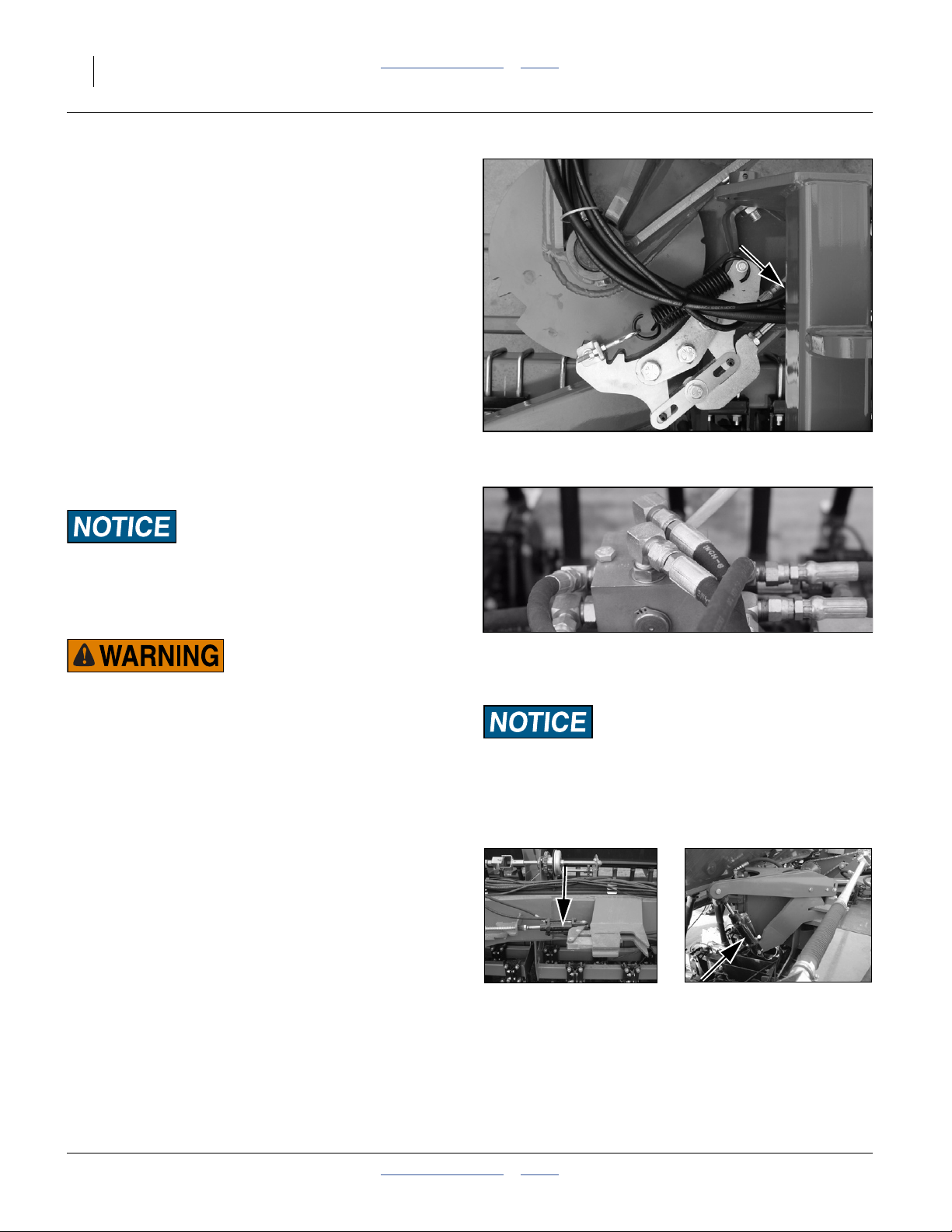
Refer to Figure 20
Figure 20
Fold: Drive/Lock Selector Valve
Pinch/Crush Risk: Drill Center section moves back while
folding. Tractor may move forward. Allow at least 10ft (3m)
clearance behind drill and ahead of tractor when folding.
21844
1. Set Drive/Lock selector valve to Lock.
2. Fold markers (Option). See page 33.
3. Raise drill with lift cylinders until cylinders are fully
extended. Install lock channels over extended
wheel-cylinder rods. Six cylinder rods total. See
page 22.
4. Retract the Lock cylinder circuit lever to:
• disengage the tool bar locks (2),
• disengage swivel locks (2),
• disengage caster locks (2), and
• enable the self-latching transport lock (1).
Set circuit to Neutral. Do not Extend.
Figure 21
Transport/Tool Bar Lock Cylinders
21841
21845
2013-10-29 Table of Contents Index 196-359M
Page 28
24 3N-4010F/3N-4010HDF/3N-4020F Table of Contents Index Great Plains Manufacturing, Inc.
Note: There are two key points to remember when oper-
ating the lock cylinders.
a. All seven lock cylinders are plumbed together,
and all move at the same time.
b. Operate the lock circuit lever (Retract/Neutral)
only once to fold. As the cylinders move, they
unlock 6 points then stop in a “ready to fold
position.” When the drill is folded, the 7th lock,
spring loaded, snaps shut, locking the drill.
5. Extend the Fold cylinder circuit lever to slowly fold
wings forward. The transport lock automatically captures the right wing tool bar for transport.
Note: It may be necessary to ease forward slightly with
the tractor to assist wings in folding completely.
Unfolding the Drill
Machine Damage Risk:
Unfold only when the drill is raised and locked up.
Unfold the drill on level ground with the tractor transmission in neutral.
Crushing, Pinch-Point and Overhead Hazards:
To prevent serious injury or death:
▲ Always use transport locks when drill is folded.
▲ Fold only if hydraulics are bled free of air and fully charged
with hydraulic oil.
▲ Stay away from frame sections when they are being raised
or lowered.
▲ Keep away and keep others away when unfolding drill.
Note: When unfolding, operate the lock circuit exactly in
reverse of folding. Operate the circuit once (Extend/Neutral). Remember that when the cylinders
move, they release one lock, and enable six others,
stopping in a “ready to unfold” position. As the drill
is unfolded, the six spring loaded locks snap shut,
locking the drill.
Refer to Figure 23
1. Check selector valve set to Locks.
Figure 22
27183
Swivel Lock Cylinder
Figure 23
21844
Unfold: Drive/Lock Selector Valve
Pinch/Crush Risk:
Center section of drill moves forward while unfolding.
Tractor may move backward. Keep all personnel clear of drill
and tractor wheels.
Figure 24
Transport/Tool Bar Lock Cylinders
21841
21845
196-359M Table of Contents Index 2013-10-29
Page 29

Great Plains Manufacturing, Inc. Table of Contents Index Operating Instructions 25
2. Extend the Lock cylinder circuit lever to:
• disengage the self-latching transport lock,
• enable two tool bar locks,
• enable two swivel locks, and
• enable two caster locks.
Set circuit to Neutral. Do not Retract.
Refer to Figure 18 and 19 on page 22
3. Raise the drill. Remove lock channels from all six
wheel cylinders. Store lock channels.
4. Activate fold hydraulics and slowly unfold the drill
until wings are fully unfolded and all spring loaded
locks have snapped into position.
Figure 25
Caster Lock Cylinder
21842
5. Lower drill.
Refer to Figure 23
6. Move selector valve handle from Locks to Drive.
2013-10-29 Table of Contents Index 196-359M
Page 30
26 3N-4010F/3N-4010HDF/3N-4020F Table of Contents Index Great Plains Manufacturing, Inc.
Transport
Electrocution Hazard:
To prevent serious injury or death from electric shock, keep
clear of overhead power lines when transporting, folding,
unfolding or operating drill components. Machine is not
grounded. At higher voltages, electrocution can occur without
direct contact.
Great Plains recommends transporting the drill without
seed loaded. Although designed for highway movement
with full seed boxes, the additional weight of seed may
cause the drill to exceed the rated towing and stopping
ability of the tractor, makes the drill more difficult to control and stop, and increases wear on tires and wheel
bearings.
Make sure the tractor weighs at least
drill, including any material load. Check the table at the
bottom of this page for weights of various configurations.
2
⁄
(67%) of the
3
Loss of Control Hazard:
Towing the drill at high speeds or with a vehicle that is not
heavy enough can lead to loss of vehicle control. Loss of vehicle control can lead to serious road accidents, injury and
death. To reduce the hazard:
▲ Do not exceed 20 mph (32 kph).
▲ Do not tow a drill that weighs more than 1.5 times the
weight of the towing vehicle.
Typicala Transport Weights
3N-4010F 3N-4010HDF 3N-4020F
Rows 7.5in 10in 7.5in 10in 7.5in 10in
Empty,
no markers, no weights
Empty,
w/markers and weights
Full Seed Load,
no markers, no weights
Full Seed Load,
w/markers and weights
a. Weights do not include row unit accessories or other options. If table weight is near recommended limit for the tractor,
obtain a precise weight for the empty drill at a scale.
28260 lbs
12819 kg
32142 lbs
14579 kg
34404 lbs
15605 kg
38286 lbs
17366 kg
26660 lbs
12093 kg
30542 lbs
13854 kg
32804 lbs
14880 kg
36686 lbs
16640 kg
29540 lbs
13399 kg
33422 lbs
15160 kg
35684 lbs
15605 kg
39566 lbs
17366 kg
27620 lbs
12528 kg
31502 lbs
14289 kg
33764 lbs
15315 kg
37646 lbs
17076 kg
31652 lbs
14357 kg
35534 lbs
16118 kg
37796 lbs
17144 kg
41678 lbs
18905 kg
29204 lbs
13247 kg
33086 lbs
15008 kg
35348 lbs
16034 kg
39230 lbs
17794 kg
196-359M Table of Contents Index 2013-10-29
Page 31

Great Plains Manufacturing, Inc. Table of Contents Index Operating Instructions 27
Pre-Transport Checklist
Before transporting the drill, check and observe the following items.
❑ Make sure the weight of the tractor equals or exceeds
the value specified for your drill configuration.
❑ Marker Checklist Complete
Markers must be folded.
❑ Master Switches Off
Check that the Veris and point row (if any) master
switches are off while transporting.
❑ Drill Raised and Locked
Lift transport locks installed.
Wings folded and locked, with circuit lever in neutral.
❑ Tires
Check that all tires are properly inflated as listed on
“Tire Inflation Chart” on page 125.
❑ Bystanders
Check that no one is in the way before moving. Do not
allow any one to ride on the drill.
❑ Warning Lights
Always use tractor and drill warning lights when transporting the drill.
❑ Clearance
Know the maximum dimensions of the tractor and drill
in transport position and follow a route that provides
adequate clearance from all obstructions, including
overhead lines.
See “Specifications and Capacities” on page 125.
❑ Stopping Distance
Allow sufficient stopping distance and reduce speed
prior to any turns or maneuvers. If the drill is transported full, allow extra stopping distance.
❑ Road Rules
Comply with all national, regional and local laws when
transporting on public roads.
❑ Watch Traffic
The drill boxes obstruct a portion of your rear view. Be
prepared for sudden maneuvers from following vehicles.
Figure 26
Marker in Transport Cradle
18857
2013-10-29 Table of Contents Index 196-359M
Page 32

28 3N-4010F/3N-4010HDF/3N-4020F Table of Contents Index Great Plains Manufacturing, Inc.
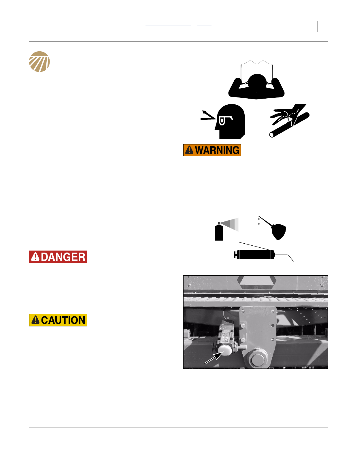
Loading Seed
To unload seed, see “Seed Cleanout” on page 101.
Misstep Hazard:
Watch your step when walking on drill ladder and walkboard.
Falling from drill could cause severe injury or death.
Great Plains recommends loading materials after the drill
has been transported to the planting ground.
Seed is heavy. A full load of dense seed adds over 6000
pounds (2780 kg) to the drill. Pre-loading substantially
increases transport hazards:
• Stopping distance increases.
• Turns are more difficult to initiate and more difficult to
stop, due to the inertia of the load.
To load materials:
1. Load only in dry conditions.
2. If the seed is treated, wear protective equipment rec-
ommended for the hazards.
3. Lower the drill.
4. Open the lids for the boxes.
5. Remove any debris or obstructions from the boxes. If
other seed needs to be first removed, see “Seed
Cleanout” on page 101.
6. If not planting all rows, shut off unused rows. See
page 66.
7. Load seed. Load or spread materials evenly across
all partitions. Use a tool or gloved hand.
8. Make a note of the quantity loaded, for later confir-
mation of population or application density desired.
9. Close and secure the box lids.
WARNING
To avoid serious injury or death:
Watch your step when climbing ladder or
walking on walkboard.
838-102C
No Seed Lubricants
Fluted-feed materials do not require lubricants.
838-102C
818-323C
25477
196-359M Table of Contents Index 2013-10-29
Page 33

Great Plains Manufacturing, Inc. Table of Contents Index Operating Instructions 29
Planting
Seed Rate
Seed rate on this family of drills is controlled by:
• Seed rate handles.
• Seed cup door handles.
• Rate set by the hydraulic drive console.
Set Seed Rate Handle
Refer to Figure 27
There are main box seed rate handles for each section of
the drill (3 handles total). All must be set identically.
The seed rate handle controls the percent engagement
of the seed sprocket in the seed cups. The setting of the
handle is given by the chart on page 40. These settings
have been chosen based on the seed size, and a coarse
rate that allows the hydraulic drive to provide optimal fine
rate control. Once set, the handles are not adjusted.
To set a handle:
6
1. Loosen wing nut under handle.
2. Consult the chart on page 40 for your seed and rate
range. Note the Rate Handle setting provided.
6
7
3. Move indicator to a scale value about 10 higher
than the setting from the chart. Then move handle
back to the chart setting.
4. Tighten wing nut.
Set Seed Cup Door
Refer to Figure 28,
which depicts the seed cup door handle in position .
At each seed tube, adjust the seed cup door handle
for the seed size.
The handle has three normal operating position detents:
(top detent) is for the smallest seeds.
1
Use it for wheat and similar small seeds.
(middle detent) is for larger seeds.
2
Use it for soybeans and similar larger seeds.
(bottom detent) is for oversize or fragile seeds.
3
If you experience excessive cracking with
setting , use setting .
Note: Handle position is used for clean-out (page 101),
2 3
not planting. If set to this position with seed loaded,
it may be difficult to reset it to a normal operating
position.
7
3
5
4
Figure 27
Seed Rate Handle
5
1
2
3
Figure 28
Seed Cup Door Handle
28181
4
26211
2013-10-29 Table of Contents Index 196-359M
Page 34

30 3N-4010F/3N-4010HDF/3N-4020F Table of Contents Index Great Plains Manufacturing, Inc.
About Hydraulic Drive Rate
Before it can control seed rate, the console must be:
• configured with information about your drill and
intended planting speed,
• configured with a calibration number for the seed and
rate range, and;
• calibrated to fine-tune the calibration number and
speed.
This process is described starting on page 39.
Refer to Figure 29
With those steps completed, field seeding rate is controlled manually by adjusting the target “set=” rate
using the ⇑/⇓ arrow buttons. Field rate can also be controlled by a pre-loaded “recipe” or an external GPS controller.
In field operation, the hydraulic drive console displays:
set= the currently active desired seeding rate
out= the current system seeding rate
spd= (over number), the current speed
Seeding Depth
Refer to Figure 29
Seeding depth is controlled by coulter depth in
front, and press-wheel height in back. Seed cannot be
placed any deeper than coulter depth. Before adjusting
row units, make sure coulters are performing as desired.
See “Level Frame Side to Side” on page 102.
See “Level Frame Front to Rear” on page 102.
See “Frame-Mounted Coulters” on page 63.
See “10 Series Opener Depth” on page 74.
Consistent seeding depth relies on appropriate
down-pressure for conditions.
See “Frame Weight” on page 68.
See “10 Series Row Unit Down Pressure” on page 71.
For information on opener adjustments, see one of:
“10 Series Row Unit Adjustments” on page 70
“10HD Series Row Unit Adjustments” on page 75
“20 Series Row-Unit Adjustments” on page 84
For information on troubleshooting opener problems, see
“Troubleshooting” on page 90.
1 2
3
Figure 29
Console Planting Display
2 1
Figure 30
Seeding Depth
28325
3
27070
196-359M Table of Contents Index 2013-10-29
Page 35

Great Plains Manufacturing, Inc. Table of Contents Index Operating Instructions 31
Point Row Switches
The hydraulic drive motor operates whenever the speed
radar detects motion. The Point Row system determines
whether or not that motion is coupled to the meter drives,
by controlling the electric clutches. The implement lift
switch is part of the Point Row system.
A Point Row troubleshooting chart is found on page 92.
Refer to Figure 31
Note: The Pump switch has no function on 3N-40
drills configured byGreat Plains. Unless connected
to field-installed equipment, leave it off.
P
When Not Planting or Calibrating
Set the Master switch OFF when you do not intend to
meter seed.
Entanglement Hazard:
If the hydraulic drive system is on, and the drill is lowered (or
the Master switch is in CAL), unexpected motion of chains,
sprockets, shafts and seed meters can occur if the speed radar
detects motion, such as someone moving near the radar.
M
Normal Full Pass
1. Set Master switch ON (up)
Set all sections ON (up).
Check that corresponding lamps are on.
2. Height switch automatically energizes clutches when
row units are lowered.
M
L C R
Point Row in Pass
3. Turn desired sections off as non-planting regions are
reached.
4. Turn the sections back on before commencing next
full-width pass.
Point Row CAL Mode
When the drill is raised, the lift switch normally causes
the Point Row Monitor to disengage the clutches for each
drill section. To keep one or more clutches engaged during hydraulic drive calibration, set the Master switch to
CAL.
For a typical 3-row calibration, set the Left section switch
L C R
on, and the center and right section switches /
off during calibration.
{
S
L
F
Cab Switch Box
RC
CAL
Figure 31
P
Switch
or
Function
Indicator
MASTER
M
Switch
MASTER
m
S
C
R
P
CAL
Lamp
Section
Lamps
L
LEFT
CENTER
RIGHT
PUMP
F
Fuse
CAL Lamp
a. However, the section’s meters may still be coupled to the
drive system, if lock-up bolts are installed in the clutch.
See page 109.
m M
b. If lamp fails to illuminate with set ON, check the
F
fuse . If open, check for damaged cable / failed clutch.
Up: ON: System enabled
Center: OFF System inactive
Down: CAL: Lift switch bypassed on
On: System enabled
Off: System OFF
On: Clutch enabled for that section.
Off: Clutch not energized
Up: section enabled
Down: section disabled
May control customer-provisioned
equipment.
Protects switch box, clutches and
b
battery.
On: Lift switch overridden
Off: Lift switch active (or system off)
a
M
28246
2013-10-29 Table of Contents Index 196-359M
Page 36

32 3N-4010F/3N-4010HDF/3N-4020F Table of Contents Index Great Plains Manufacturing, Inc.
d
r
r
Field Operations
This section presumes that all pre-operation checks have
been made on drill, and drill is hitched and loaded with
seed.
Final Field Checklist
❑ Drill unfolded and raised.
❑ Selector valve set to hydraulic drive.
❑ Hydraulic drive console set per seed rate calibration.
❑ Check all seed hoses secure.
❑ Check all row configurations identical (except where
compensating for tire tracks, etc.).
If you desire to verify that all meters and seed tubes are
working, you can run a Veris calibration for 4 seconds
(the minimum time) and “KEEP OLD” when it presents a
proposed new calibration number. See page 39.
Planting Sequence
1. All Clutch/Point Row switches up (except Pump).
Check lamps illuminated.
2. Press Veris “ON/VR” button once.
Check LED above button illuminated.
3. Pull forward to field.
4. Lower drill to field position.
5. Move lever for hydraulic drive circuit forward and lock
it open.
6. Option: Extend marker side desired.
7. Option: Shaft Monitor ON
8. Press Veris “ENGAGE” button once.
Check LED above button illuminated.
9. Accelerate to planting speed.
10. Raise drill for turns (drive stops automatically).
11. Option: Retract and extend markers at turns.
Stop early in the first pass to verify:
• Openers are at correct depth.
• Seed is flowing to furrows.
• Press wheels are covering furrows as desired.
Monitor the seed level indicators on the seed box. After a
third or more of the first seed load has been planted, stop
and check the seed boxes from above. Look for evidence
of unexpected unevenness in the seed level. There may
be mounds at any blocked rows.
Seed consumption is uneven, and end rows run out
before mid-section rows. Re-load seed when the level
indicators near Empty.
Figure 32
DICKEY-john Radar
Moving Chain Hazard
Pinch/Crush Hazard
Shaft Entanglement Hazard:
Be careful when working around drill while tractor is running.
Any movement detected by the radar gun can activate the Veris
hydraulic drive causing motion of chains, sprockets, shafts an
seed meters.
Vision Hazard:
The DICKEY-john RVS II radar speed sensor is an intentional
radiator of RF energy. Although its radiated energy level is fa
below the limits set by EN 61010-1: 1993\A2: 1995 - Chapte
12.4, it is advisable not to look directly into the face of the unit.
The radar must radiate toward the ground and at least 20 cm
(8 inches) away from a human during use to comply with the
RF human exposure limits per FCC 47 CFR Sec. 2.1091.
DO NOT mount or use the radar in a manner inconsistent with
its defined use.
Certain Machine Damage: Do not back up with openers in the
ground. To do so will cause severe damage and opener plugging.
20310
196-359M Table of Contents Index 2013-10-29
Page 37

Great Plains Manufacturing, Inc. Table of Contents Index Operating Instructions 33
Marker Operation (Option)
Markers are on a separate hydraulic circuit on the drill.
Before operating markers, make sure they are properly
bled as described in “Bleeding Markers” on page 107.
Dual markers are equipped with a sequence valve to
control lift sequence. Starting with both markers up, the
sequence is:
1. Activate tractor hydraulic lever; right marker lowers
while left marker stays up.
2. Reverse hydraulic lever; right marker raises while left
marker stays up.
3. Activate hydraulic lever; left marker lowers while right
marker stays up.
4. Reverse hydraulic lever; left marker raises while right
marker stays up.
5. Pattern repeats.
Folding speed of dual markers is adjusted with adjustment screws on sequence valve body. Because exces-
sive folding speed may damage markers, adjust markers
to a safe folding speed according to “Marker Speed” on
page 107.
Note: To get both markers in the lowered position at the
same time, activate hydraulic lever to lower one
marker. After marker is lowered, move lever to
opposite position then quickly reverse lever and
hold until other marker is lowered.
Shaft Monitor Operation (Option)
Refer to Figure 33
To operate the optional shaft monitor, turn the system on
via the ON-OFF switch.
During normal movement, the indicator lamps for each
section are on steady, indicating that shaft rotation is
detected.
If the seed-cup shaft stops for 30 seconds or more, an
alarm sounds and the lamp for the affected section
flashes.
The 30-second delay is to prevent nuisance alarms when
turning at the end of passes.
If a shaft failure does occur, remember that you have
traveled for 30 seconds without planting under the
affected section.
For installation, see:
“Shaft Monitor (Option)” on page 18.
For ordering information, see:
“Shaft Monitor” on page 121.
3
1
2
3
2
Figure 33
Shaft Monitor Console
1
18943
2013-10-29 Table of Contents Index 196-359M
Page 38

34 3N-4010F/3N-4010HDF/3N-4020F Table of Contents Index Great Plains Manufacturing, Inc.
Parking
Following these steps when parking the drill for periods
of less than 36 hours. For longer periods, see Storage,
the next topic.
1. Spot the drill on firm, level ground.
2. Raise the drill. Install transport locks.
3. Fold as necessary for the parking space available.
4. Securely block drill tires to prevent rolling.
Roll-Away Hazard
Always block drill tires when unhitching. There is not enough
weight on tongue to anchor drill using parking jack.
Do NOT unhitch on a steep slope.
Always unhook safety chain LAST.
Figure 34
Drill on Parking Stand
20273
Storage
Store the drill where children do not play. If possible,
store inside for longer life, or cover with tarp.
5. Unload seed boxes. See page 101.
6. Lubricate the drill at all points listed under “Lubrica-
tion” on page 114.
7. Check all bolts, pins, fittings and hoses. Tighten,
repair or replace parts as needed.
8. Check all moving parts for wear or damage. Make
notes of any parts needing repair before the next
season.
9. Plug or cap seed delivery tubes to prevent pest entry.
10. Grease exposed cylinder rods to prevent rust. Be
sure to completely de-grease before next use, to prevent seal damage.
11. Use touch-up paint to cover scratches, chips and
worn areas to prevent rust.
196-359M Table of Contents Index 2013-10-29
Page 39

Great Plains Manufacturing, Inc. Table of Contents Index 35
Hydraulic Drive Operation
Drive Operational Requirements
Hydraulic System:
Closed Center, pressure compensated or load sensed
systems only
Drive will not operate on Open-Center hydraulic systems
Minimum Hydraulic Pressure 2250 psi
Maximum Hydraulic Pressure 3000 psi
Maximum Required Flow 8.5 gpm
Electrical System:
Voltage 12 volts DC
Current 4 amperes
Tractor Hookup
Hydraulics:
1. Connect pressure hose (P) to retraction outlet
2. Connect motor return hose (T) to motor return port (if
available) or to extension outlet.
3. Set flow rate at maximum required flow of 13 gpm.
4. If tractor is equipped with electro-hydraulic valves,
set timer to “constant” flow.
High Pressure Fluid Hazard: Escaping fluid under pressure
can penetrate skin, causing serious injury. Avoid the hazard by
relieving pressure before disconnecting hydraulic lines. Use a
piece of paper or cardboard, NOT BODY PARTS, to check for
leaks. Wear protective gloves and safety glasses or goggles
when working with hydraulic systems. If an accident occurs,
seek immediate medical attention from a physician familiar
with this type of injury.
Moving Chain Hazard: Return hydraulic drive circuit lever to
Neutral before exiting tractor cab. Unexpected drive rotation
can cause serious injury.
22715
Electrical:
Refer to Figure 35
Power must be connected directly to the battery. Make
sure that eyelets are properly connected (red to positive,
black to negative). Connect female socket to power port
adapter.
Disconnect all cables and remove VER-21568 Ext. Control
module before welding on drill. See page 100.
Figure 35
Controller Electrical Connection
2013-10-29 Table of Contents Index 196-359M
22714
Page 40

36 3N-4010F/3N-4010HDF/3N-4020F Table of Contents Index Great Plains Manufacturing, Inc.
Controller Menu
ON / VR
set= * spd=
PRESET RATES
PRESET
selected
PRESET 1
*
PRESET 2
*
PRESET 3
*
FUNCTION
FUNCTION
FUNCTION
FUNCTION
SPEED CALIBRATION
UP:CALIBRATE
DN:RESTORE
CAL SETTINGS
*
FUNCTION
PRESS ENGAGE
AT 1 ST F LAG
ENGAGE
___ft ENGAGE AT
2ND FLAG
ENGAGE
DISTANCE ERROR
____%
FUNCTION
UP:CALCULATE NEW
DN:KEEP CURRENT
KEY
set = * spd=
out = ______ _. _
FUNCTION ENGAGE
ON / VR
- cab console LCD screen
- Condition for progressing to next screen
* Adjust number up/down or toggle between selections using
the keys.
** Refer to the troubleshooting section of the manual for a
description of error messages.
23251
out= ______ _._
FUNCTION
CALIBRATION
NUMBER *
FUNCTION
recipe format
*
VERIS V1
selected
FUNCTION
manual/preset
*
MANUAL
selected
FUNCTION
PRESS UP KEY TO
CALIBRATE RATE
FUNCTION
PRESS UP KEY TO
CALIBRATE SPEED
FUNCTION
- Keys on cab console
VARIABLE RATE
FUNCTION
RAWSON NOMINAL
*
RAWSON
selected
FUNCTION
FUNCTION
invalid
time
**
ENGAGE
FUNCTION:EXIT
FUNCTION
RATE CALIBRATION
CAL SETTINGS
*
CAL SETTINGS
WIDTH *
CAL SETTINGS
# ROWS *
CAL SETTINGS
SPEED *
ENTER TARGET
AMOUNT *
FUNCTION
FUNCTION
calibration
error
**
valid
time
TIME TO RUN FOR
CAL ___s
CLEAR DRIVE AREA
UP:CLEAR DN:EXIT
ENGAGE:RUN DRIVE
FUNCT:EXIT
___s out= ______
ENGAGE TO STOP
ENTER AMOUNT
COLLECTED *
NEW CAL #: ____
OLD CAL #: ____
UP:KEEP NEW
DN:KEEP OLD
FUNCTION
FUNCTION
FUNCTION
FUNCTION
FUNCTION
FUNCTION
ENGAGE
calibration
successful
FUNCTION
FUNCTION
196-359M Table of Contents Index 2013-10-29
Page 41

Great Plains Manufacturing, Inc. Table of Contents Index Hydraulic Drive Operation 37
Console Functions
Refer to Figure 36 (depicting the console in Manual mode)
• ON/VR button:
turns drive system on.
Press twice for VR (Variable Rate) mode.
• OFF button:
used to shut off Console.
Note: This also turns off power to the external control-
ler module and ground speed radar.
• FUNCTION button:
used in Calibration modes, and to programming Presets and downloading recipes.
• ⇑/⇓ Arrow buttons
used to change rates manually, enter setup data and
select options.
• ENGAGE button:
press to start drive.
Figure 36
Controller Button Functions
Note: ENGAGE button must also be pressed to start
drive operation.
Note: Drive does not run unless light above both ON/VR
and ENGAGE buttons are illuminated.
22710
Basic Operation
Power Up
Refer to Figure 36
To power-on the controller, press the ON/VR button
once. This powers up the console in Manual mode, and
also powers up the external module on the drill (if connected).
The green LED above the button illuminates, and a display appears showing:
set= the currently active seeding rate
Shortly thereafter the display also shows:
spd= (over 0.0), the current speed, and
out= 0.0, the current system operating rate.
Once the console is powered up, the ON/VR button toggles between Manual and VR (Variable Rate) mode.
Note: It is possible to enter all setup information with the
console connected to power, but disconnected
from the drill. Operations requiring motion, such
as calibrations, must be performed hitched (but
generate harmless errors if undertaken with only
the console powered).
Seed Rate
In Manual mode, use the ⇑/⇓ arrow buttons to set the
desired seed rate (in pounds/acre or kg/ha). Or use
FUNCTION to select Preset mode, and the ⇑/⇓ arrow
buttons to alternate between preset rates (see page 54).
In VR mode, the seed rate is set by an external “recipe”
program or external controller. The ⇑/⇓ arrow buttons can
override the current rate. VR mode is not documented in
this manual.
Power Off
Press the OFF button to shutdown.
2013-10-29 Table of Contents Index 196-359M
Page 42

38 3N-4010F/3N-4010HDF/3N-4020F Table of Contents Index Great Plains Manufacturing, Inc.
Hydraulic Drive Field Operations
Refer to Figure 37
1. Turn on Controller Console by pressing the ON/VR
button. Green light above ON/VR button illuminates
when power is on.
Pressing the ON/VR button twice puts the unit in VR
mode. VR appears on the screen along with the Rate
from the recipe or sent from your GPS. Press ON/VR
button again to toggle back to manual mode. (Mode
and rate changes take effect with the release of the
button.)
2. To change rates manually whether in Manual or in
VR mode, simply touch the
⇑/⇓ arrow buttons. This
changes the Controller to the rate you select manually. To return to VR, simply touch the ON/VR button
to toggle back to VR mode.
3. Before planting, conduct a seed rate Calibration
(page 39) and ground speed Calibration (page 51).
4. Engage the hydraulic flow by pushing FORWARD on
the tractor remote hydraulic lever. The remote lever
must be LOCKED OPEN in this position to provide
constant flow to the drive motor.
John Deere tractors with Sound-Gard® body:
Use lever lock clip to lock lever forward. See your
tractor dealer for lock purchase and installation.
John Deere 7000 Series tractors: Rotate valve
detent selector to motor position to lock lever in forward position.
John Deere 8000 Series tractors: Set timer to continuous. Push lever forward until detent clicks.
Case-IH Magnum tractors: Lock lever forward in
detent position. You may need to turn up detent pressure to its maximum setting. Do not tie hydraulic
lever past detent position with a strap. See your trac-
Figure 37
VR (Variable Rate) Mode
tor dealer for details.
Other tractors: Lock lever forward in detent position.
You may need to turn detent pressure to maximum
or use a mechanical detent holder to hold lever forward. See your tractor dealer for proper means of
providing constant flow.
5. Press ENGAGE button to activate drive. Green light
above ENGAGE button illuminates.
Note: If you do not move within 10 seconds, the auto-
matic disengagement feature disengages the
drive. To begin planting again, press ENGAGE.
6. The Console display shows two numbers while operating: “Set” rate is the rate you tell the system to
plant, and the “Out” rate is the calculated rate based
on the actual rotations of the drive. The “Out” reading is monitoring the drive system; it isn’t monitoring
population. It verifies that the drive system is functioning properly.
Note: The “Out” readings normally fluctuates within 5%
of the “Set” rates. This fluctuation is evidence of
the drive system compensating for normal variations in ground speed.
28273
7. If “Out” rate varies from the “Set” rate by more than
20%, an audible alarm sounds.
8. If Controller is powered directly from the battery or
via unswitched power port, make sure to power Console off when tractor is shut down, in order to prevent
tractor battery drain.
When calibrating, make sure that you choose a calibration speed that is representative of your average planting
speed.
196-359M Table of Contents Index 2013-10-29
Page 43

Great Plains Manufacturing, Inc. Table of Contents Index Hydraulic Drive Operation 39
Seed Rate Calibration
Seed rate calibration consists of:
a. Setting up to collect seed at one
cally 3), using an approximate calibration number.
b. Running the hydraulic drive (with drill stationary) for
a short period of time, twice:
- once to prime the seed cups, and
- once to generate the sample.
c. Weighing the collected seed, and determining
amount per row.
d. Entering that weight on the console. The controller
uses it to calculate a more precise Cal. number.
Tools required:
• small container(s) to capture seed at one or more
openers, and
• a scale with a capacity great enough to weigh the container(s)+seed, and precise enough to register the difference between that and the empty container(s).
a
or more rows (typi-
Figure 38
Calibration: Initial Screen
28251
Seed Rate Calibration Steps
In the steps which follow, the examples are based the
configuration at right.
1. Unfold the drill.
The wing drive shafts cannot turn with the drill
folded. U-joint damage will occur if attempted.
2. Load an amount of seed, equal to about twice the
expected sample size, over one or more rows near
the end of the left wing seed box. The expected
amount of seed is determined by you. The controller
calculates the run-time necessary to generate that
amount at a single row.
Great Plains suggests sampling an amount that is at
1
least
⁄
lb (0.1 kg), and requires at least 100 sec-
4
onds. At typical planting speeds, this is about one
row for one acre (or one row for half a hectare).
Divide your intended seed rate by your row count.
SeedRate
SampleSize (lbs)
SampleSize (kg)
3. Raise and lock-up the drill if capturing seed below
openers.
-------------------------
=
RowCount
SeedRate
----------------------------------
=
RowCount 2×
Example drill configuration:
Model: 3N-4010F-4810
Row spacing: 10 in
RowCount = 48
Seed: long grain rice
Desired seed rate: 50 pounds/acre
Sample size for our example:
SeedRate = 50 (lbs/ac)
RowCount = 48
1.04 = 50 / 48
SampleSize is 1.04 lbs
Load 2 lbs or more for testing.
a. For short run times and/or small samples, increase the accuracy of the results by sampling multiple rows, and calculating the average.
For adjacent rows, pull the seed hoses off at the opener, and route them to a common collection container.
2013-10-29 Table of Contents Index 196-359M
Page 44

40 3N-4010F/3N-4010HDF/3N-4020F Table of Contents Index Great Plains Manufacturing, Inc.
Hydraulic Drive Calibration
source: ./charts/veris40fc-cal.ods -> Export as .pdf -> convert to .eps in Illustrator.
196-359M Table of Contents Index 2013-10-29
Page 45

Great Plains Manufacturing, Inc. Table of Contents Index Hydraulic Drive Operation 41
Refer to Figure 39
m
4. Set the Point Row switch box for Calibration mode:
• LEFT section switch on.
• CENTER and RIGHT section switches off.
• Master switch to “CAL”
Confirm CAL lamp illuminated.
5. Take steps to capture and measure seed from the
three outside rows of the left wing.
If seed a loaded at more rows, take steps to recover
seed from non-sampled rows on the left section.
6. Set the seed rate handles all sections to the chart
value (page 40). See page 29 for handle operation.
7. Set the feeder cup doors, drill wide, per page 29.
Refer to Figure 40
M
CAL
M
CAL
Figure 39
Point Row in Calibration
28329
8. Turn on Controller Console by pressing ON/VR but-
ton. Green light above ON/VR button illuminates.
9. Use ⇑/⇓ arrow buttons to set desired planting rate,
the example, 50.0 pounds/acrea.
Note: Set the desired rate before performing a calibra-
tion, as this value is used by the controller to calculate sample run time. If the rate is not set, the
sample run time will be incorrect, or you may get
“TIME TOO LOW/HIGH” errors that cannot be
cleared by adjusting the expected sample size.
Refer to Figure 41
10. Press FUNCTION button until CALIBRATION NUM-
BER window appears.
11. Select drive calibration number based on row spac-
ing and seed, from “Hydraulic Drive Calibration”
on page 40. You may also use an initial value developed from a previous calibration of similar seed.
12. Use ⇑/⇓ arrow keys to set Calibration number.
Figure 40
Controller Button Functions
Figure 41
Calibration Number
28249
28250
If no sample-based calibration is desired, press
FUNCTION to cycle to initial screen.
a. The controller ignores units of measure at step 9. If you change units at step 15, the numeric value entered at step 9 is unchanged.
2013-10-29 Table of Contents Index 196-359M
Page 46

42 3N-4010F/3N-4010HDF/3N-4020F Table of Contents Index Great Plains Manufacturing, Inc.
Refer to Figure 42
13. Press Function button until the Calibration window
appears as shown.
14. Press ⇑ arrow button to enter calibration mode.
Refer to Figure 43
15. This is the first window that appears in Calibration
mode. Press FUNCTION button to accept, or ⇑ button to change units of measure.
ENGLISH (U.S. Customary) units are:
pounds/acre, pounds, feet and mph
METRIC units are:
kg/hectare, kilograms, meters and kph
If you change units of measure for rate calibration, it
also changes units for speed calibration.
Refer to Figure 44
Note: When units of measure is changed, all previous
and subsequent values entered or computed are
assumed to be in the new units, but their numeric
values are not converted.
For example, if you entered a rate of 50.0 (intending
lbs/ac) at step 9, and switched to metric mode at
step 15, the seed rate is left at 50.0 and taken to be
50.0 kg/ha during any calibration and planting.
Figure 42
Initiate Sample Calibration
Figure 43
U.S. Customary Units
28251
28252
Which changing units of measure, be sure to
re-check all other settings, and convert any as required.
196-359M Table of Contents Index 2013-10-29
Figure 44
Metric Units
28248
Page 47

Great Plains Manufacturing, Inc. Table of Contents Index Hydraulic Drive Operation 43
Refer to Figure 45
16. Enter drill width (swath), in feet (ENGLISH mode) or
meters (METRIC mode), using
⇑/⇓ arrow buttons.
Press FUNCTION button to advance to next window.
Swath values for various row spacings are found in
the charts beginning on page 127. Your value may
not be, for example, precisely 40.0 ft.
The controller uses this value to determine the calibrated motor rate-vs-ground speed needed to seed
at your desired rate.
Figure 45
28253
Cal. Mode Drill Width
Refer to Figure 46
17. Enter number of rows here using
⇑/⇓ arrow buttons.
Press FUNCTION button to advance to next window.
The controller uses this value in determining the
sample run-time (which is based on 1 row).
Refer to Figure 47
18. Enter your planned planting speed using ⇑/⇓ arrow
buttons. Calibration mode does not accept a speed
higher than 10 mph or 16 kph. Press FUNCTION
button to advance to next window.
Although the calibration sample is collected with the
drill stationary, the controller operates the hydraulic
drive at the same rpm that would be used in the field
for this speed.
Figure 46
Cal. Mode Row Count
28245
Figure 47
28254
Cal. Mode Speed
2013-10-29 Table of Contents Index 196-359M
Page 48

44 3N-4010F/3N-4010HDF/3N-4020F Table of Contents Index Great Plains Manufacturing, Inc.
Prime Seed Meters
Before running an actual calibration, it is important that
the seed cups be filled with seeds, and the flutes primed
to deliver seed at first rotation. Step 19 through step 30
executes a short calibration to do this.
If the cups are already primed, skip to step 31.
Refer to Figure 48
19. Enter a small target amount.
Refer to Figure 49
20. It may take some experimenting to select a value
that avoids “TIME TOO LOW” errors.
Press FUNCTION button to return to step 19.
Note: If modest adjustments to the sample size continue
to result in HIGH/LOW errors, chances are some
other parameter is zero or incorrect by a large factor (such as decimal place error). To start over,
press OFF, and then ON.
Refer to Figure 50
21. The minimum time is 4 seconds. Select a time just
long enough to ensure that the meters are filled with
seed, and seed is flowing to all seed tubes to be
sampled.
Figure 48: Priming:
Set for Short Run Time
Figure 49: Priming:
Time Limit Error
28308
28257
Figure 50: Priming:
28309
Short Cal. Mode Time
196-359M Table of Contents Index 2013-10-29
Page 49

Great Plains Manufacturing, Inc. Table of Contents Index Hydraulic Drive Operation 45
Refer to Figure 51
22. Press FUNCTION. The console beeps and displays
this screen, indicating that the drive is about to operate, and all personnel must be cleared from the area
near the hydraulic drive, chains and shafts. There is
a danger of entanglement if anyone is in the drive
area.
Moving Chain Entanglement Hazard:
Be sure to verify that no one is near the drive area before
advancing to the next step.
Figure 51: Priming:
28258
Cal. Mode Clear Area
Refer to Figure 52
23. Move the hydraulic motor circuit level lever forward to
supply oil to motor.
24. Only after you have verified the drive area is clear,
press the up arrow button to initiate calibration mode.
The console beeps again.
If drive area isn’t clear, press Down arrow button to
abandon the calibration. This skips to the next item
in the main FUNCTION menu rotation (speed calibration, page 51).
25. Continuing to verify that the drive area is clear, press
the ENGAGE button to start drive rotation.
To terminate priming, press ENGAGE.
Refer to Figure 53
26. While the drive is rotating, the display window shows
the time remaining and the “Out” rate.
The “out=” rate is the estimated area planting rate,
based on motor performance, and is not related to
the sample size. The example screen at right is halfway through the priming, and the actual motor rate is
slightly high.
CONTINUE TO MONITOR DRIVE AREA DURING DRIVE
ROTATION. PRESS THE ENGAGE BUTTON (OR OFF
KEY) TO STOP DRIVE DURING CALIBRATION
Figure 52: Priming:
Cal. Mode Initiate Motion
Figure 53: Priming:
Mode Prompt In Motion
28259
28310
2013-10-29 Table of Contents Index 196-359M
Page 50

46 3N-4010F/3N-4010HDF/3N-4020F Table of Contents Index Great Plains Manufacturing, Inc.
Refer to Figure 54
27. When the sample run-time has expired, the motor
stops, the indicator above the ENGAGE button goes
out, and the console displays the estimated sample
generated (based on actual motor performance,
which may vary slightly from calculations).
The number display is normally very close to the
sample size entered at step 19.
28. Press the OFF button on the console.
29. Return hydraulic motor circuit lever to Neutral.
30. Exit the tractor cab. Return metered seed to seed
box.
Figure 54: Priming:
Mode Normal Completion
28311
Refer to Figure 56
If you see the screen at right, the console has detected
an error. The most common problem is that motor rotation has not been detected. Check:
• all cables connected
• hydraulic fluid supply to motor
This screen is a normal and harmless condition if you are
operating the console disconnected from the drill.
Figure 55:
Cal. Mode Error
28318
196-359M Table of Contents Index 2013-10-29
Page 51

Great Plains Manufacturing, Inc. Table of Contents Index Hydraulic Drive Operation 47
Full Calibration
Make sure the seed meter cups are full, and seed can
flow at initial motor rotation. To prime the cups, see
page 44.
Refer to Figure 56
31. Turn the console on with the ON/VR button. Check,
and as necessary, repeat step 1 through step 18.
32. Enter the amount of seed you want to measure. This
should be at least
1
⁄
of a pound (0.1 kg). Press
4
FUNCTION button to advance to next window.
The amount shown at right is from the example estimate at step 2.
Refer to Figure 57
33. Normally, the console display informs you of the
length of time, in seconds, that the drive will be operating, in order to meter the amount of seed you have
requested, at the calibration number, drill width, and
number of rows you have selected. Press FUNCTION button to advance to next window.
Refer to Figure 58
34. If the screen reads instead:
TIME TOO LOW, or
TIME TOO HIGH,
change the amount of seed that you will count or
measure. For calibration accuracy, the Controller
firmware does not allow calibrating at settings that
would result in the drive rotating for less than 4 seconds, or more than 255 seconds.
Figure 56
Cal. Mode Seed Target
Figure 57
Cal. Mode Time Window
28255
28256
Press FUNCTION button to return to step 31.
Note: If modest adjustments to the sample size continue
to result in HIGH/LOW errors, chances are some
other parameter is zero or incorrect by a large fac-
Figure 58
Cal. Mode Time Limit Error
28257
tor (such as decimal place error). To start over,
press OFF, and then ON.
2013-10-29 Table of Contents Index 196-359M
Page 52

48 3N-4010F/3N-4010HDF/3N-4020F Table of Contents Index Great Plains Manufacturing, Inc.
Refer to Figure 59
35. Press FUNCTION. The console beeps and displays
the next screen indicating that the drive is about to
operate, and all personnel must be cleared from the
area near the hydraulic drive, chains and shafts.
There is a danger of entanglement if anyone is in the
drive area.
Moving Chain Entanglement Hazard:
Be sure to verify that no one is near the drive area before
advancing to the next step.
Refer to Figure 59
Figure 59
28258
Cal. Mode Clear Area
36. Only after you have verified the drive area is clear,
press the up arrow button to initiate calibration mode.
The console beeps again.
If drive area isn’t clear, press ⇓ Down arrow button to
abandon the calibration. This skips to the next item
in the main FUNCTION rotation (speed calibration,
page 51).
Refer to Figure 60
37. Continuing to verify that the drive area is clear, press
the ENGAGE button to start drive rotation.
To terminate calibration mode, press the ENGAGE
or OFF buttons.
Refer to Figure 61
38. While the drive is rotating, the display window shows
the time remaining and the “Out” rate.
The “out=” rate is the estimated area planting rate,
based on motor performance, and is not related to
the sample size. The example screen at right is halfway through the sample collection, and the actual
motor rate is slightly high.
Figure 60
Cal. Mode Initiate Motion
28259
CONTINUE TO MONITOR DRIVE AREA DURING DRIVE
ROTATION. PRESS THE ENGAGE BUTTON (OR OFF
Figure 61
Cal. Mode Prompt In Motion
28260
KEY) TO STOP DRIVE DURING CALIBRATION
196-359M Table of Contents Index 2013-10-29
Page 53

Great Plains Manufacturing, Inc. Table of Contents Index Hydraulic Drive Operation 49
Refer to Figure 62
39. When the sample run-time has expired, the motor
stops, the indicator above the ENGAGE button goes
out, and the console displays the estimated sample
generated (based on actual motor performance,
which may vary slightly from calculations).
The number display is normally very close to the
sample size entered at step 31.
40. Exit the tractor cab and obtain the net weight of the
samples. If multiple rows were sampled, divide the
total seed weight by the number of row sampled.
SampleWeight GrossWeight ContainerWeight–=
SampleWeight
AmountCollected
----------------------------------
=
RowsSampled
Refer to Figure 63
41. Enter the actual amount metered per row using the
⇑/⇓ arrow buttons.
Press FUNCTION button to advance to next window.
Figure 62
Cal. Mode Normal Completion
Example:
Three 4 oz. containers were used at 3 rows.
ContainerWeight = (4 x 3 /16), or
0.75 lbs.
Weight of containers and metered seed was:
GrossWeight = 3.66 lbs.
SampleWeight = 3.66 - 0.75, or
2.91 lbs.
AmountedCollected = 2.91 / 3, or
0.97 lbs.
28261
Figure 63
28262
Cal. Mode Enter Seed Count
2013-10-29 Table of Contents Index 196-359M
Page 54

50 3N-4010F/3N-4010HDF/3N-4020F Table of Contents Index Great Plains Manufacturing, Inc.
Refer to Figure 64
42. A new calibration number is suggested, along with
the old calibration number.
Refer to Figure 65
43. Press FUNCTION button to advance to the choice
window.
If you wish to keep the old number, perhaps to re-run
the calibration procedure, press the ⇓ Down arrow
button.
To accept the New calibration number, press the ⇑
Up arrow button.
Refer to Figure 66
44. Console window displays the calibration number you
have selected.
The console is once again at step 10. If the calibration just completed resulted in a Cal number change
of more than a few percent, validate or further refine
it by running a new calibration, skipping the Priming
step 19 through step 30.
Rate calibration results, once accepted by you, are
stored until changed, and are not lost when power is
removed.
Note: Cautious practice includes a furrow inspection to
ensure that actual seed placement and spacing is
as expected. This can be done by setting one or
more rows to shallow operation, tying up the press
wheel (or locking up a 10HD row), for a short distance.
Figure 64
New/Old Calibration Number
Figure 65
Calibration Number Choice
Figure 66
Calibration Number Accepted
28263
28264
28265
196-359M Table of Contents Index 2013-10-29
Page 55

Great Plains Manufacturing, Inc. Table of Contents Index Hydraulic Drive Operation 51
Speed Calibration
In order to fine-tune the default speed calculation or to
convert to radar speed signal, the controller may be calibrated as follows:
1. Set two flags 400ft apart (100 meters if in metric
mode).
Refer to Figure 67
2. To calibrate the Controller for speed, press the
FUNCTION button until the screen at right appears.
Refer to Figure 68
3. Press the
⇑ Up arrow button to initiate new speed
calibration routine.
Press the ⇓ Down arrow button to restore factory
default setting.
Refer to Figure 69
4. This is the first window that appears in Speed Calibration mode. Press FUNCTION button to accept, or
⇑ button to change units of measure.
ENGLISH (U.S. Customary) speed units are:
mph (miles per hour)
Figure 67
Speed Calibration Mode
Figure 68
Initiate Speed Calibration
28266
28267
METRIC speed units are:
kph (kilometers per hour)
If you change units of measure for speed calibration,
it also changes units for seed rate. Numeric values
entered or previously computed are not converted.
Figure 69
U.S. Customary Units
28252
Be sure to review all screens before planting.
2013-10-29 Table of Contents Index 196-359M
Page 56

52 3N-4010F/3N-4010HDF/3N-4020F Table of Contents Index Great Plains Manufacturing, Inc.
Refer to Figure 70
5. Begin driving at a normal field speed; when the tractor passes the first flag, press ENGAGE.
Refer to Figure 71
6. While between flags, the display shows the distance
traveled.
Refer to Figure 72
7. When the tractor passes the second flag, press
ENGAGE again.
Figure 70
At First Flag
Figure 71
Between Flags
28268
28269
Figure 72
28270
At Second Flag
196-359M Table of Contents Index 2013-10-29
Page 57

Great Plains Manufacturing, Inc. Table of Contents Index Hydraulic Drive Operation 53
Refer to Figure 73
8. The display shows the error or difference between
the traveled distance and the distance calculated by
the Controller.
Refer to Figure 74
9. If this is the first time the unit has been calibrated,
this error can be large. Accept the new speed calibration and re-run the course. Re-calibrate until the
error is within 5%. The cab console gives you the
option each time you calibrate of accepting the new
settings, or keeping the previous setting.
Speed calibration results, once accepted by you, are
stored until changed, and are not lost when power is
removed.
10. When planting, check the speed displayed against
the tractor speedometer or other reference. If they
disagree by more than a few percent, perform
another speed calibration.
Figure 73
Distance Variance
Figure 74
Save/Ignore Result
28271
28272
2013-10-29 Table of Contents Index 196-359M
Page 58

54 3N-4010F/3N-4010HDF/3N-4020F Table of Contents Index Great Plains Manufacturing, Inc.
Varying Rates with Pre-set Function
The Precision Population Controller allows you to pre-set
three different rates, and then change rates on-the-go by
toggling from one rate to another rate with the
buttons.
⇑/⇓ arrow
Refer to Figure 75
11. To enter the three pre-set rates, press the FUNCTION button until Pre-set Menu screen appears: Use
⇑/⇓ arrow buttons to toggle from Manual mode to
pre-set mode
Refer to Figure 76, Figure 77 and Figure 78
12. Press Function button to move to the next pre-set
screen, and the Up-Down arrow keys to set the
pre-set rates.
Figure 77
28276
Preset Mode 2
Refer to Figure 79
Figure 75
Preset Mode
Figure 76
Preset Mode 1
Figure 78
Preset Mode 3
28274
28275
28277
13. When in Pre-Set mode, the main operating screen
shows the pre-set rate currently being applied.
Note: When you are in Pre-set mode, the ⇑/⇓ arrow but-
tons only toggle between pre-set rates.
Figure 79
28278
Preset Operating Mode
196-359M Table of Contents Index 2013-10-29
Page 59

Great Plains Manufacturing, Inc. Table of Contents Index Hydraulic Drive Operation 55
GPS-Based Planting
Refer to Figure 80
Both the Farmworks SiteMate computer and the Ag
Leader PF3000 GPS solutions require a 9-pin serial con-
nection to the hydraulic drive console.
FarmWorks SiteMate
Settings for FarmWorks SiteMate used with Precision
Population Controller QUICK REFERENCE GUIDE
1. Create a .shp recipe file in FarmWorks Site Pro,
1
1
SMS 2.0, SSToolbox, or other software that will create a .shp file, and transfer it to SiteMate.
SiteMate Settings: (version 8.12)
1. Select CONFIGURE Tab.
Select SETTINGS.
Select VARIABLE RATE SETUP.
Select NEW.
Type in GP PPC.
Under CONTROLLER TYPE, select
Rawson from the scroll-down list.
Under COMM PORT select the port number for the
serial card or flash jacket port.
2. Select MAP tab.
Enter DEFAULT rate.
This is the rate that SiteMate calls for if GPS signal is
lost or you are outside the map area.
3. Note: if GPS signal is interrupted, or you are outside
the map area, the Controller continues applying at
the latest rate, until signal is regained, or another
rate is set manually. If SiteMate power is interrupted,
restart the recipe to return to VR.
4. In the CONVERSION window, enter the conversion
rate as 1.
5. Under the APP tab,
enter the Feed Delay as 3 seconds.
Enter the Following Distance (the offset from the
GPS to the seed tubes) based on:
24 ft (7.32m) from hitch pin to seed tubes;
Add the distance from the GPS to the hitch pin.
Enter the total in the Following Distance window.
Figure 80: SiteMate:
Serial Connection to Controller
Enter the Step as 4%.
Exit VRA Controller Setup by clicking OK button to
save the settings.
7. Under FILE,
Open VRT and select the
Rx Map (recipe) for the field.
Press the SETUP button and select the PPC controller option you set up using these instructions.
8. Press GO.
The Rx rate window shows the rate that is being sent
to the GP Precision Population Controller. The
APPLIED window shows the rate that the GP Controller is applying.
28322
Enter the Swath Width of the Great Plains unit.
6. Under the CTRL tab,
enter the Nominal Rate as follows:
Divide the highest rate on your recipe by 1.6.
This is your Nominal rate.
If your highest rate is 32, your nominal rate is 20.
2013-10-29 Table of Contents Index 196-359M
Page 60

56 3N-4010F/3N-4010HDF/3N-4020F Table of Contents Index Great Plains Manufacturing, Inc.
GP Precision Population Settings
1. Connect SiteMate computer to Console using 9-pin
serial cable , as shown in Figure 80. Follow
instructions on page 39 to set Calibration Number.
Refer to Figure 81
2. Press FUNCTION button until a “recipe format” window appears. Use the ⇑/⇓ arrow buttons to select
RAWSON mode.
1
Refer to Figure 82
3. Press FUNCTION button until the Nominal Rate
appears on the display. Using the Up/Down arrow
keys, set the Nominal Rate to the same number as
you set the SiteMate. Once Nominal Rate is set,
press Function button until the main operating
screen appears, as shown in Figure 36 on page 37.
4. Press On/VR button again to toggle to VR mode. VR
should appear on the screen along with the Rate that
is being sent from the SiteMate computer. (See Figure 37 on page 38). Verify that the rate shown on the
GP Controller Console is the same as the recipe
sent from SiteMate. Press ENGAGE button to activate the Precision Population Controller.
5. To change rates manually when in VR mode, touch
the ⇑/⇓ arrow buttons. This changes the Controller to
the rate you select manually. To return to VR, touch
the ON/VR button to toggle back to VR mode.
Figure 81: SiteMate:
Rawson Recipe Mode
Figure 82: SiteMate:
Rawson Nominal Rate
28320
28323
196-359M Table of Contents Index 2013-10-29
Page 61

Great Plains Manufacturing, Inc. Table of Contents Index Hydraulic Drive Operation 57
Ag Leader PF3000
Settings for Ag Leader PF3000 Monitors used with Precision Population Controller QUICK REFERENCE GUIDE.
1. Create a .tgt recipe file in SMS 2.0 or FarmWorks
Site Pro, or other software that will create a .tgt file,
and copy it to an SRAM or Flash card that is compatible with the PF 3000.
PF3000 Settings:
2. Press SETUP key.
Press SWATH key.
Set swath to that of your Great Plains Precision
Seeding System.
3. Press SETUP key.
Press VEHICLE key.
Set Primary speed sensor to GPS.
1
Figure 83: PF3000:
Serial Connection to Controller
28322
4. Press SETUP key.
Press CARD key.
Set the following:
• Log Device: None.
5. Press SETUP key.
Press APP RATE key.
Set the following:
• Application Control: On
• Look Ahead: On
• Current target file: press Edit to view the files you
have on the card; select the one you wish to use.
6. Press SETUP key.
Press CONTROLLER key.
Select controller as Rawson Accu-Rate.
Press EDIT SETTINGS. Set the following:
• Number of pulses/10 revolutions: 500
• Nominal rate: Divide the highest rate on your rec-
ipe by 1.6. This is your Nominal rate. If your highest rate is 32, your nominal rate is 20.
• Percent rate change: set to 4%
• Area count: Set to Standard
• Stop height: Set to 8
• Act. rate recording method: Set to Sensor
• Controller time delay: Set to 4 sec.
• Application offset from GPS:
24 ft (7.32m)
Add the distance from the hitch pin to your GPS
location.
• Serial Port: Port 3
7. Press SETUP key.
Press PRODUCT key.
Select product and press EDIT SETTINGS.
Set the following:
• Controller Device: Rawson Accu-RateCal. number
for act. rate: set to 0
• Actual Rate Scale Factor: Set to 1.000
• Target Rate Units: Set to Seeds
• Actual Rate Units: Set to Seeds
• Target conversion Number: 1
• Target Rate increment: Determines the increment
value by which you can change the manual target
rate with each press of the arrow keys.
8. Press FIELD key.
Set Field.
Set Product (press button to right of product)
2013-10-29 Table of Contents Index 196-359M
Page 62

58 3N-4010F/3N-4010HDF/3N-4020F Table of Contents Index Great Plains Manufacturing, Inc.
Precision Population Settings
1. Connect PF3000 to Console using 9 pin serial cable
per Figure 83 on page 57.
2. Set Calibration Number per page 39.
Refer to Figure 84
3. Press FUNCTION button until a “recipe” screen
appears. Use the ⇑/⇓ arrow buttons to select RAWSON mode.
Refer to Figure 82
4. Press FUNCTION button until the Nominal Rate
appears on the display.
Using the ⇑/⇓ arrow buttons, set the Nominal Rate to
the same number as you set the PF3000 in step 5
above. Once Nominal Rate is set, press FUNCTION
key until main operating screen appears.
5. Press On/VR key again to toggle to VR mode. VR
should appear on the screen along with the Rate that
is being sent from the PF3000. Verify that the rate
shown on the GP Controller Console is the same as
the recipe sent from the PF3000.
Press ENGAGE button to activate the Precision Population Controller.
6. To change rates manually when in VR mode, simply
touch the ⇑/⇓ arrow buttons. This changes the Controller to the rate you select manually. To return to
VR, touch the ON/VR button to toggle back to VR
mode.
Figure 84: PF3000:
Rawson Recipe Mode
Figure 85: SiteMate:
Rawson Nominal Rate
28320
28323
196-359M Table of Contents Index 2013-10-29
Page 63

Great Plains Manufacturing, Inc. Table of Contents Index 59
Adjustments
To get full performance from your drill, you need an
understanding of all component operations, and many
provide adjustments for optimal field results.
The 3N-4010F, 3N-4010HDF and 3N-4020F have double-disk parallel-arm openers with depth-controlling
press wheels. This system provides accurate depth control and seed placement over uneven terrain. The following is an introduction to the basic seeding components
and how they work.
Each opener is mounted on a floating opener frame, held
parallel to the ground. Opener bodies are staggered for
easy soil flow. A spring provides the down pressure necessary for opener double disks to open a seed furrow.
The spring allows openers to float down into depressions
and up over obstructions. Trailing press wheels close the
furrow. Individual openers can be adjusted to account for
tire tracks.
Even if your planting conditions rarely change, some of
these adjustment items need periodic attention due to
normal wear.
Planting Depth
Setting nominal planting depth, and achieving it consistently, is affected by multiple adjustable drill functions,
from greatest to least effect they are:
• Coulter Height;
• Opener Depth (Press Wheel and/or Side Wheel)
• Row Unit Down Pressure;
• Frame Weight;
• Disk Blade Adjustments (as blades wear).
Adjustment Page The Adjustment Affects
Level Frame Side to Side 102 Center-vs-wing planting consistency
Level Frame Front to Rear 102 Correct seeding depth and furrow coverage
Implement Lift Switch Adjustment 67 Avoiding wasted and unplanted seed
Coulter Frame Height 63 Seeding depth
Individual Frame-Mounted Coulter Depth 65 Compensating for tire tracks
Frame Weight 68 Compensating for unusually light or heavy conditions
Frame Weight 68 Achieving higher down-force settings
Marker Extension 18 Pass alignment
Marker Adjustments 69 Mark visibility
Row Unit Adjustments Series: 10 10HD 20
Overview 70 75 84
Unit-Mount Coulter Adjustments - 76 - Furrow preparation and seeding depth
Row Unit Down Pressure 71 78 85 Consistent seeding depth in tire tracks
Opener Disk Blade Adjustments 72 80 86 Consistent seeding depth
Depth Gauge Wheel Adjustments - - 86 Seeding depth
Seed Firmer Adjustments 73 81 88 Consistent seed placement and coverage
Press Wheel Height 74 82 89 Seeding depth (10/10HD), furrow closure (all)
2013-10-29 Table of Contents Index 196-359M
Page 64

60 3N-4010F/3N-4010HDF/3N-4020F Table of Contents Index Great Plains Manufacturing, Inc.
Frame Level
When beginning planting, check frame level with row
units in level ground.
If one or both wings are angled up or down, check and
adjust the following items:
•“Level Frame Side to Side” on page 102
• coulter depth setting - see “Frame-Mounted
Coulters” on page 63
• coulter mount adjustment - see “Individual
Frame-Mounted Coulter Depth” on page 65
• coulter down-force spring setting - see “Frame
Weight” on page 68
• row unit down-force spring setting - see:
“10 Series Row Unit Down Pressure” on page 71
“10HD Row Unit Down Pressure” on page 78
“20 Series Row-Unit Down Pressure” on page 85
• press-wheel height setting - see:
“10 Series Opener Depth” on page 74
“10HD Press Wheel Adjustments” on page 82
“20 Series Press Wheels” on page 89
Frame Height
Frame height is determined by an adjustable hydraulic
depth control valve, and has a significant effect on planting depth.
Frame height adjustment methods depend on coulter
configuration. Frame-mounted coulters (FMC) are standard on some 3N-40 models and optional on others. The
3N-4010HDF accepts either FMC or unit-mount coulters
(UMC), although only one type of coulter can be installed
simultaneously.
For adjustments:
Refer to Figure 86
1. Frame-Mounted Coulters (FMC)
frame height information begins on page 63.
2. Unit-Mounted Coulters (UMC, 10HDF only)
frame height information begins on page 76.
3. No Coulters
use the same frame height setup as UMC, page 76.
1 2 3
Figure 86
Coulter Configurations
27211
196-359M Table of Contents Index 2013-10-29
Page 65

Great Plains Manufacturing, Inc. Table of Contents Index Adjustments 61
Frame Height without Frame-Mounted Coulters
Use these instructions with a drill having no coulters, or
having unit-mounted coulters (UMC). Adjustments to
individual unit-mounted coulters themselves (10HD models only) are on page 76.
If the drill has frame-mounted coulters, use the height
procedure on page 63.
Refer to Figure 87
Frame height is measured from the bottom of the
opener tool bar (the largest of the tool bars), and is measured with the drill lowered.
The recommended height depends on your field conditions (see table below), and whether unit-mounted
coulters are installed.
Conditions Unit
Light no-till, or conventional tillage, with unitmounted coulters or no
coulters
Moderate to challenging
no-till with unit-mounted
coulters
1
1
3N-4010HDF
3N-4010F
3N-4020F
3N-4010HDF
3N-4010F
3N-4020F
Opener
Tool Bar Height
Above 26in (66cm)
Above 24in (61cm)
Above 24in (61cm)
At 26in (66cm)
At 24in (61cm)
At 24in (61cm)
27213
1
Figure 87
UMC/NC Frame Height
27214
For no-till conditions, a 26in (66cm) height allows the
opener parallel arms to run parallel to the ground giving
the opener the maximum upward or downward flotation.
In loose or conventional planting conditions, a frame
height above 26in (66cm) helps keep the no-till spring
forces from burying the openers.
Note: Setting the frame above the 26in (66cm) limits the
opener downward flotation.
Note: Running with the frame below 26in (66cm) limits
opener upward flotation and could cause opener
damage especially at center of the drill.
2013-10-29 Table of Contents Index 196-359M
Page 66

62 3N-4010F/3N-4010HDF/3N-4020F Table of Contents Index Great Plains Manufacturing, Inc.
Crushing Hazard:
Make all down-stop adjustments with circuit in neutral and
drill raised (actuator plunger not in contact with down-stop).
Loosening the down-stop with circuit active and drill lowered
results in rapid lowering of the frame.
Height Mis-setting Risk:
Make sure the drill is level and the lift system bled and
re-phased before adjusting the tool bar height. If the center
section does not consistently stop at the set height, or the
wings do not run at the same height as the center, the lift system may have air or be out of phase (above), or the wings may
not be level. See “Frame Alignment and Level” on page 101.
Refer to Figure 88
The lift system includes an adjustable stop valve to fix
1
the height of the opener frame when the drill is lowered.
To adjust the stop height:
1. Move to smooth level ground representative of field
conditions.
2. Lower the drill and measure the present tool bar
height. If the drill cannot be fully lowered due to row
unit spring settings, temporarily move the cams to a
lower setting, or out of notch entirely.
3. Raise the drill.
4. Loosen the knob on the stop .
5. Adjust the stop position on the tube . Adjust up
2 3
3 4
(to raise) or down (to lower). Adjust by half the last
difference. Secure the stop with the knob bolt .
2
6. Lower the drill and measure the tool bar height. If the
error is more than about
1
⁄
in (3mm), repeat the
8
adjustment process from step 3.
7. Raise and lower several times and confirm that the
drill stops consistently at the new height.
Note: It is important that all tires remain in ground contact
to maintain frontto rearlevelness. Setting the depth
control too deep combined with high opener spring
force can cause the drill to tip forward when planting, which may cause plugging.
4
2
1
5
3
Figure 88: UMC/NC:
Opener Depth Stop
20274
Running with the front tires floating or skimming on
the ground will cause uneven coulter depth and
may cause uneven seed depth.
196-359M Table of Contents Index 2013-10-29
Page 67

Great Plains Manufacturing, Inc. Table of Contents Index Adjustments 63
Frame-Mounted Coulters
The factory configuration of frame-mounted coulters
(FMC) is that they run about 1in (2.5cm) deeper than the
opener blades. Based on your conditions and experience, you can readjust the depth drill-wide, or just at
some rows.
Frame-mounted coulters, as factory-installed, are used
“in row” and not “zone”. They are intended to prepare the
soil directly ahead of the seed furrow.
With frame-mounted coulters, the coulter depth controls
opener depth and performance. Set the frame height to
achieve the desired coulter depth.
There are three adjustments for frame-mounted coulters:
Refer to Figure 89
4
5
6
1. Frame height - the running depth of all coulters as a
group. This is set by a hydraulic stop, the next topic.
2. Individual coulter depth - a mechanical adjustment
for a few rows in tire tracks. See page 65.
3. Individual coulter down-force - this is a spring adjustment for rows in tracks, or all rows - in unusually light
or heavy no-till conditions. See page 66.
Frame Height - Frame Mounted Coulters
Refer to Figure 90
In regular or heavy no-till conditions, set
7
the coulter depth to about 1in (2.5cm) deeper than
8
seeding depth.
For example, if
8
the desired seeding depth is 1in (2.5cm), set
7
the coulters to run at 2in (5.1cm) deep.
Setting coulters too deep for conditions can cause
opener plugging and uneven or too-deep seed depth. In
light no-till or conventional till conditions, it may be necessary to set coulter depth to less than 1in (2.5cm)
below seeding depth , or even
ing depth.
In addition to checking depths at setup, be sure to check
actual seeding results while planting.
7
8
1
/
in (6mm) above seed-
4
Figure 89: FMC:
Coulter Adjustment Points
7 8
Figure 90: FMC:
Coulter to Opener Depth
20274
27215
27070
2013-10-29 Table of Contents Index 196-359M
Page 68

64 3N-4010F/3N-4010HDF/3N-4020F Table of Contents Index Great Plains Manufacturing, Inc.
Crushing Hazard:
Make all down-stop adjustments with circuit in neutral and
drill raised (actuator plunger not in contact with down-stop).
Loosening the down-stop with circuit active and drill lowered
results in rapid lowering of the frame.
Height Mis-setting Risk:
Make sure the drill is level and the lift system bled and
re-phased before adjusting the tool bar height. If the center
section does not consistently stop at the set height, or the
wings do not run at the same height as the center, the lift system may have air or be out of phase (above), or the wings may
not be level. See “Frame Alignment and Level” on page 101.
Refer to Figure 91
Note: The change in coulter height is greater than the
change in down-stop adjustment. Make adjustments in small amounts.
The lift system includes an adjustable stop valve to fix
1
4
1
the height of the opener frame when the drill is lowered.
To adjust the stop height
(assuming a desired 1
1
⁄
in / 3.2cm coulter depth):
4
2
5
1. Move to smooth level ground with soil as similar as
possible to field conditions.
3
2. Lower the drill until the coulter blades just touch the
ground. Hold that height by setting the lift circuit to
neutral.
3. Loosen the knob on the stop .
4. Adjust the stop position on the tube until it just
touches the actuator .
5. Raise and then fully lower the drill.
6. Pull forward 10 feet (3m) and stop.
196-359M Table of Contents Index 2013-10-29
2 3
3 4
5
Figure 91: FMC:
Opener Depth Stop
20274
Page 69

Great Plains Manufacturing, Inc. Table of Contents Index Adjustments 65
7. Measure the depth at which the coulters are running.
Measure only in non-tire-track rows where the
coulter springs are not in compression (arm is at full
extension). If the coulters are at the desired depth,
no further adjustment is necessary. Skip to step 11.
8. Raise the drill and set the lift circuit to neutral.
9. Adjust the stop up (to raise depth) or down (to lower
depth). Adjust in small increments. Secure the stop
with the knob on the bolt .
2
10. Check the new setting starting at step 5.
11. Raise and lower several times and confirm that the
Note: It is important that all of the tires remain in contact
with the ground to maintain levelness of machine
from front to rear. Setting the depth control too
deep combined with high opener spring force can
cause the drill to tip forward when planting, which
may cause plugging.
Running with the front tires floating or skimming on
the ground will cause uneven coulter depth and
may cause uneven seed depth.
drill stops consistently at the new height.
Before making any adjustments to individual
frame-mounted coulters, setup the seeding depth on the
row units, and verify that the coulter tool bar height is set
for your conditions.
Individual Frame-Mounted Coulter Depth
The running depth of all coulters is adjusted simultaneously by changing the tool bar height. Adjusting the
height of a small number of coulters may be useful for
rows in tire tracks.
Adjust individual coulters as follows.
1. On level ground, lower the drill until coulters just
touch the ground.
2. Raise the drill by the extra amount you need to lower
the rows in tracks.
Refer to Figure 92
3
2
1
3. At each frame-mounted coulter to be adjusted,
slightly loosen all six bolts ( , ) at the mount.
4. Using a rubber mallet, tap the spring bar up or
1 2
3
down until the bottom edge of the coulter disk is at
ground level.
5. Tighten the two clamp bolts until both U-bolts are
firmly against the edge of the spring bar . It is nor-
mal for there to be a small gap between the clamps.
6. Tighten the four U-bolts .
7. Lower the drill to planting height and pull forward 30
1
3
2
Note: A gap of as much as
Frame-Mounted Coulter Height
Figure 92
1
⁄
in (3mm) betweenthe clamp
8
10300
plates is normal.
feet (10m).
8. Check coulter blade to opener blade (furrow centerline) alignment.
2013-10-29 Table of Contents Index 196-359M
Page 70

66 3N-4010F/3N-4010HDF/3N-4020F Table of Contents Index Great Plains Manufacturing, Inc.
Frame-Mounted Coulter Force
Coulter springs are set to 400 lbs (181 kg). In normal
operation at target running depth, the spring is at full
extension. It compresses briefly as obstructions are
encountered.
• In heavy no-till conditions, you may observe the
springs in compression most of the time. This means
that the blades are not reaching the desired coulter
depth. If adequate drill weight is available, you can
increase the spring down-force to compensate.
• In light but rocky conditions, the factory spring setting
may be higher than needed. You can extend blade life
by reducing the force at which the blades ride up over
obstructions.
To adjust the coulter spring:
Refer to Figure 93
1. Raise the drill and install transport locks. See “Lift /
Lower” on page 22.
1
3
2
2. Determine the new spring length desired. See the
1
table at right.
3. Measure the current length of the spring(s) to be
changed. If already shorter than 9
longer than 10
1
⁄
in (26cm), do not further adjust
4
3
⁄
in (24.8cm), or
4
them.
4. Loosen the jam nut .
5. Rotate the adjuster nut until the spring is at the
2
3
new length. Tighten the jam nut.
Note: If all springs are continuously in compression, the
coulters can lift the wing frames off the ground (at
the wheels), resulting in uneven coulter depth
and/or uneven seed depth. If high forces are required, frame weights are probably required.
Row Unit Shut-Off
To shut off seed flow to individual rows, such as to operate with an alternate row spacing, there are two or three
steps involved:
Refer to Figure 94
1. Block the seed flow to the row with an optional seed
tube plug. See page 121 for ordering.
2. Re-calculate the drill’s swath, and check for any
changes needed to:
• marker extension (see pages 18 and 127) and
• calibration (step 16 on page 43).
3. On 10HD Series, reduce needless wear on the
unused rows by locking them up. See page 80.
Figure 93
27139
Frame-Mounted Coulter Spring
Spring Length
1
Force at Blade
10.25 in (26.0 cm) 300 lbs (136 kg)
10.00 in (25.4 cm) 400 lbs (181 kg)
9.75 in (24.8 cm) 525 lbs (238 kg)
Equipment Damage Risk: Do not use spring lengths shorter
than 9.75 in (24.8 cm). It may contribute to premature parts
failure which will not be covered by warranty.
Figure 94
26279
Block Seed Tubes
196-359M Table of Contents Index 2013-10-29
Page 71

Great Plains Manufacturing, Inc. Table of Contents Index Adjustments 67
Implement Lift Switch Adjustment
Refer to Figure 95
A switch on the drill turns seed metering off (via the
electric clutches) when the drill is raised. To adjust the
height at which seed metering stops, follow these steps.
1. Do not place any part of body under implement while
2. Locate the lift switch on the left hand rockshaft.
3. Lower the implement until it is at a height where
4. Turn off the tractor and remove the key.
Refer to Figure 96
5. Loosen the cam clamp on the rockshaft and turn
1
making adjustments.
seeding should start (usually just above the ground).
Securely support frame at this height with jack
stands or blocks.
2
until the switch roller is just starting to make contact
with the ramp surface .
3
1
Figure 95
Implement Lift Switch
20303
2
3
Figure 96
Implement Lift Cam Adjust
Refer to Figure 96
6. Raise the implement fully and check that the switch
is compressed. If adjustments are made to hydraulic
coulter depth, re-check switch engagement.
Note: If coulter depth is adjusted, re-check lift switch op-
eration.
15160
2
3
Figure 97
Switch in Lift (Compressed)
2013-10-29 Table of Contents Index 196-359M
14550
Page 72

68 3N-4010F/3N-4010HDF/3N-4020F Table of Contents Index Great Plains Manufacturing, Inc.
Frame Weight
In challenging no-till conditions, some row-unit
down-pressure settings (across all rows), and many
frame-mounted coulter settings, may be high enough to
lift the wing caster wheels off the ground. To avoid inconsistent results, add weight to the wings.
One or two pairs of (four total) weight brackets are
optional. The weights required are common “suitcase”
tractor weights, and are widely available, although not
supplied by Great Plains.
Each bracket accepts up to five standard weights, about
500 lbs (227 kg) per wing, or 1000 lbs (454 kg) per kit.
Great Plains recommends loading no more than two sets
of brackets, representing 2000 lbs (907 kg) total.
Do not add weight to the center section. It is always
heavier than even a fully weighted wing, and never
requires additional weights.
Available Down Force
Each Weight set assumed to be fully populated with five
100 pound weights.
Installing Frame Weights
Additional Weight Available to Each Row
3N40-6475
Wing Configuration
1 Weight Kit (no markers) 48 lbs (22 kg) 63 lbs (28 kg)
Marker (no weight kits) 90 lbs (41 kg) 118 lbs (53 kg)
2 Weight Kits (no markers) 95 lbs (43 kg) 125 lbs (57 kg)
Marker and 1 Set 137 lbs (62 kg) 180 lbs (82 kg)
Marker and 2 Weight Sets 185 lbs (84 kg) 243 lbs (110 kg)
Note: This table does not include the effect of adding
frame-mounted coulters to the drill.
Although frame-mounted coulters add 61 lbs (28
kg) to each row, they also rely on the available
weight per row, and can easily require more weight
than they contribute.
Although this reduces the weight available to the
openers, the opener workload is also reduced by
having the furrow prepared by the coulters.
7.5in (64 Rows)
Figure 98
3N40-4810
10in Rows (48 Rows)
27068
196-359M Table of Contents Index 2013-10-29
Page 73

Great Plains Manufacturing, Inc. Table of Contents Index Adjustments 69
Marker Adjustments
This section covers marker items that may need adjustment for current conditions, and assumes that the markers are installed, set to the correct initial extension and in
proper working order. See also:
•“Marker Setup (Option)” on page 18
•“Marker Maintenance” on page 107
Marker Disk Adjustment
W
1
N
T
T
2
Sharp Object Hazard:
Marker disks may be sharp. Use caution when making adjustments in this area.
Adjusting Mark Width
Refer to Figure 99
T
is the direction of travel.
To change angle of cut, and the width of the mark, loosen
1
⁄
-inch bolts holding the disk assembly.
2
For a wider mark , increase the angle of the marker
with respect to the tube . For a narrower mark ,
2
W
1
N
reduce the angle.
Tighten bolts .
2
Direction of Cut
Refer to Figure 100
To have the marker throw dirt out, invert the disk on the
spindle, and invert the disk assembly.
Figure 99
Marker Disk Angle
T
Figure 100
Marker Disk Inverted
11757
11248
2013-10-29 Table of Contents Index 196-359M
Page 74

70 3N-4010F/3N-4010HDF/3N-4020F Table of Contents Index Great Plains Manufacturing, Inc.
10 Series Row Unit Adjustments
Refer to Figure 101
(which depicts a row unit fully populated with all optional
accessories supported for use with the 3N-4010F drill)
From front to back, a Great Plains 10 Series row unit can
include the following capabilities (some optional):
1. Dual Down Pressure Springs: standard
Each row unit is mounted on the planter via parallel
arms which allow the row unit to independently move
up and down while remaining parallel to the ground.
The adjustable spring provides the force to get the
row unit and attachments into the soil.
2. Row Unit Spring Cam: standard
This adjustment sets the down-force used by the row
unit. See “10 Series Row Unit Down Pressure” on
page 71.
3. Disc Blades: standard, 2 per row unit
Double disc blades open a furrow, creating the seed
bed. Spacers adjust the blades for a clean furrow.
See “10 Series Disk Blade Adjustments” on
page 72.
4. Seed delivery tube: standard
No adjustments are necessary.
5. Disk Scraper: optional
In sticky soils, a scraper helps keep the opener disks
operating freely. An optional carbide scraper is available. See page 123.
6. Seed firmer: seed flap (not shown) standard:
Keeton seed firmer (not shown)
Improves seed-soil contact, and provides a stable
arm for a low-rate liquid fertilizer delivery tube. See
“10 Series Keeton Adjustment” on page 73.
2
7
4
5
7
1
3
10 Series Row Unit
6
Figure 101
26414
Seed-Lok™ firming wheel (shown)
Improves seed-soil contact. See “10 Series
Seed-Lok™ Lock-Up” on page 74.
7. Press wheels: standard (choice of types)
These close the seed trench. The wheels also support the free end of the row unit, and provide the primary control over seeding depth. See “10 Series
Opener Depth” on page 74.
196-359M Table of Contents Index 2013-10-29
Certain Machine Damage:
Do not back up with row units in the ground. To do so will
cause severe damage and row unit plugging.
Page 75

Great Plains Manufacturing, Inc. Table of Contents Index Adjustments 71
10 Series Row Unit Down Pressure
Refer to Figure 102
The ideal amount of down-force causes the press wheels
to compress any loose surface soil, but not press a
trench into subsoil.
To assess down-force, operate the drill for a short distance on typical ground (with or without seeding), and
stop. Leave the drill lowered (row units in ground).
At several row units, inspect the furrow created by the
opener discs and closed by the press wheels.
Note: Be sure to inspect rows both in and out of tire
tracks.
Refer to Figure 103
1. If the press wheels are leaving no tracks, or light
tracks, increase down-force.
2. If the wheels are compressing trash and loose soil,
and leaving clear tracks right at the top of the subsoil, down-force is probably correct and needs no
adjustment.
3. If the wheels are creating a trench into the subsoil,
down-force is too high and needs to be reduced.
Adjusting 10 Series Down Force
The springs allow the row units to float down into depressions and up over obstructions.
On 10 Series row units, the seed trench is primarily
opened by the coulters. Row unit springs provide only
additional assistance needed to make a furrow “V”
shaped and ensure furrow closure by the press wheels.
Often, the rows may be run at the minimum spring setting, other than in tire tracks, which commonly need
some adjustment.
If trench depth is not being achieved across all rows,
adjust the force and/or depth of the coulters before making row unit spring adjustments.
If you cannot achieve enough down force, adding a
weight kit may help. See “Dual Weight Kit” on page 120.
Figure 102: 10 Series:
Checking Furrow
Light or no press wheel
tracks
Press wheel(s) compress
loose soil only
Press wheel(s)
making deep tracks
Figure 103: 10 Series:
Assessing Down-force
1
Inspect Furrow Here
Insufficient down-force
Increase down-force
Ideal
No adjustment required
2
Down-force too high
Reduce down-force
3
{
26414
2013-10-29 Table of Contents Index 196-359M
Page 76

72 3N-4010F/3N-4010HDF/3N-4020F Table of Contents Index Great Plains Manufacturing, Inc.
Adjusting 10 Series Down-Force
Refer to Figure 104
An adjuster cam sets row unit spring down pressure individually for each row unit. This is useful for penetrating
hard soil and planting in tire tracks.
Cam Notch Pounds
zero (out of notch) Maintenance Only
one 100 lbs (445 N)
two 116 lbs (516 N)
three 140 lbs (623 N)
tip Do Not Use
Refer to Figure 105
To adjust down pressure, use the spring adjustment tool
(part 198-126H) stored behind the tool bar at the
Slow-Moving-Vehicle placard.
1. Raise the drill. Although this adjustment can be
made with the drill lowered, the springs will be in tension, and will require more effort. The extra force
required may also damage tools.
2. Put tractor in Park and shut it off.
3. Position tool in the holes.
4. Pull upper spring link back.
5. Move the adjustment cam to the new setting on the
spring adjust bar.
Note: Do not set all rows higher than notch two. Using
high settings across all rows causes uneven planting. Individual rows may be set higher if running in
tire tracks.
Figure 104: 10 Series:
Row Unit Minimum & Maximum
Figure 105: 10 Series:
Adjusting 10 Series Springs
12104
12105
10 Series Disk Blade Adjustments
Opener disc angle and stagger is not adjustable, but
disc-to-disc spacing is, and may need attention as discs
experience normal wear. Spacers will need to be reset
when blades are replaced.
Refer to Figure 106
The ideal spacing causes the blades to be in contact for
about one inch. If you insert two pieces of paper between
the blades, the gap between them should be 0.5 to
1.75in (13 to 44mm).
If the contact region is significantly larger or smaller (or
there is no contact at all), it needs to be adjusted by moving one or more spacer washers. If the contact region
varies with blade rotation, one or both blades is likely
bent and in need of replacement.
Figure 106: 10 Series:
Checking Disk Contact
196-359M Table of Contents Index 2013-10-29
26447
Page 77

Great Plains Manufacturing, Inc. Table of Contents Index Adjustments 73
Adjusting 10 Series Disc Contact
Sharp Object Hazard:
Row unit disk blades may be sharp. Use caution when making
adjustments in this area.
Refer to Figure 107
2
1. Raise the drill and install the transport locks.
2. Remove the bolt retaining the opener disc on one
side. Carefully remove the disc, noting how many
spacers are outside the disk and inside the disk. Do
not lose the hub components and spacer washers.
3. To reduce the spacing between the discs (the normal
case), move one spacer washer from the inside to
the outside of the disc.
4. Re-assemble and check disc contact.
10 Series Seed Firmer Adjustments
10 Series row units include a seed flap, and accept one
of two optional seed firmers.
The seed flap requires no adjustment, but may need to
be replaced if worn, and may need to be shortened if an
optional seed firmer is added after initial delivery.
Sharp Object Hazard:
Row unit disk blades may be sharp. Use caution when making
adjustments in this area.To adjust the Keeton Seed Firmer,
lower the planter until the disks of the row units are resting on
the ground.
10 Series Keeton Adjustment
The optional Keeton Seed Firmer is an engineered polymer shape that slides down the seed trench. It traps
seeds as they exit the seed tube and firms them into the
bottom of the “V”.
Refer to Figure 108
1
3
3
3
3
Figure 107: 10 Series:
Adjusting Disk Spacers
26385
1
The Firmer is provided with a preset tension which is recommended for using the first year. The tension screw
can be tightened in subsequent years according to your
needs. Firmers should provide just enough tension to
push seeds to the bottom of the trench.
2013-10-29 Table of Contents Index 196-359M
1
Figure 108: 10 Series:
Keeton Seed Firmer
26390
Page 78

74 3N-4010F/3N-4010HDF/3N-4020F Table of Contents Index Great Plains Manufacturing, Inc.
10 Series Seed-Lok™ Lock-Up
Optional Seed-Lok firming wheels provide additional
seed-to-soil contact. The wheels are spring loaded and
do not require adjusting. In some wet and sticky conditions the wheels may accumulate soil. To avoid problems
associated with this, you can lock-up the firmers.
Refer to Figure 109 (which depicts a row unit with the opener
blades removed for clarity)
To lock up Seed-Lock wheels:
1. Hook one end of chain in opener-body hole just
above wheel arm .
1
2
1
3
2. Pull firming-wheel arm up as high as possible and
wrap chain around arm .
3. Hook other end of chain in a link. Leave no slack in
chain; secure wheel arm in its highest position.
2
3
10 Series Opener Depth
(Press Wheel Height)
Seeding depth on 3N-4010F, 3N-4010HDF and
3N-4020F is set by coulter depth and row unit depth. Set
coulter depth before making row unit depth adjustments.
10 Series press wheel height is a stop adjustment and
not a spring adjustment. It establishes a fixed relationship between opener depth and closed-furrow surface at
the press wheel
Refer to Figure 110
Set opener seeding depth by adjusting press-wheel
height . To adjust, first raise openers slightly, then lift
and slide T handles on top of openers Adjust all press
wheels to the same height.
• For more shallow seeding, slide T handles forward
• For deeper seeding, slide T handles backward
If press wheels are lifting off ground, check front-to-back
level, and increase row unit spring down force.
If press wheels are digging into ground, reduce spring
down force at the row units.
1
2
F
toward implement.
B
away from implement.
Figure 109: 10 Series:
Seed-Lok™ Lock-Up
F
2
Figure 110: 10 Series:
Initial Opener Depth
16856
B
1
12100
196-359M Table of Contents Index 2013-10-29
Page 79

Great Plains Manufacturing, Inc. Table of Contents Index Adjustments 75
10HD Series Row Unit Adjustments
Refer to Figure 101
(which depicts a row unit fully populated with all optional
accessories supported for use with the 3N-4010HDF
drill)
From front to back, a Great Plains 10HD Series row unit
can include the following capabilities (some optional):
1. Unit-Mounted Coulter (UMC): optional
UMCs are used instead of frame-mounted coulters
and are often preferred where soils are not rocky.
2. Dual Down Pressure Springs: standard
Each row unit is mounted on the drill via parallel
arms which allow the row unit to independently move
up and down while remaining parallel to the ground.
The adjustable spring provides the force to get the
row unit and attachments into the soil.
3. Row Unit Spring Cam: standard
This adjustment sets the down-force used by the row
unit. See “10 Series Row Unit Down Pressure” on
page 71.
4. Row-Unit Lock-Up: hole standard, pin optional
If rows are shut off with seed tube plugs, row unit
wear can be reduced by locking them up. 10HD Row
Unit Lock-Up.
5. Disc Blades: standard, 2 per row unit
Double disc blades open a furrow, creating the seed
bed. Spacers adjust the blades for a clean furrow.
See “10 Series Disk Blade Adjustments” on
page 72.
6. Scraper Separator: standard
No adjustments are necessary.
7. Seed delivery tube: standard
No adjustments are necessary.
8. Seed firmer:
reduces seed bounce and aids emergence by pressing seed gently into the furrow.
A seed flap (not shown) is standard.
1
1
Certain Machine Damage:
Do not back up with row units in the ground. To do so will
cause severe damage and row unit plugging.
2
4
4
3
5
Figure 111
10HD Series Row Unit
7
4
6
7
27064
Keeton seed firmer (not shown)
Improves seed-soil contact, and provides a stable
arm for a low-rate liquid fertilizer delivery tube. See
“10 Series Keeton Adjustment” on page 73.
Seed-Lok™ firming wheel (shown)
Improves seed-soil contact. See “10 Series
Seed-Lok™ Lock-Up” on page 74.
9. Press wheels: standard (choice of types)
These close the seed trench. The wheels also support the free end of the row unit, and provide the primary control over seeding depth. See “10 Series
Opener Depth” on page 74.
2013-10-29 Table of Contents Index 196-359M
Page 80

76 3N-4010F/3N-4010HDF/3N-4020F Table of Contents Index Great Plains Manufacturing, Inc.
Unit-Mounted Coulter Adjustments
Unit-mounted coulters (UMC) are an optional alternative
to frame-mounted coulters. Only one type of coulter may
be installed. See page 122 for ordering information.
Note: Unit-Mount Coulters are not factory-installed.
Check alignment and depth prior to first use.
10HD Coulter Depth Adjustment
Check frame height before making any UMC adjustments. See “Frame Height without Frame-Mounted
Coulters” on page 61.
The ideal operating depth for unit-mounted coulters is
1
⁄
in above opener depth. Although they may have origi-
4
nally been set to this depth, coulter (and opener) blades
wear with time, and may need adjusting.
Adjusting the coulter depth is accomplished by re-mounting the coulter blade in one of the six mounting holes
arranged in a staggered pattern in the coulter bracket.
Refer to Figure 112 and Figure 113
Figure 112: 10HD Series:
10HD Series Unit-Mounted Coulter
7
22817
Raise drill and install cylinder locks before working on
coulters. Row unit may be fully lowered or locked up. Do
not attempt to move blade when the current or new position causes it to contact the ground during the adjustment. Be careful around the front end of row units.
Coulter blades may be sharp.
To adjust coulter depth:
1. Determine the present opener and coulter depths.
2. Note which bracket hole the coulter is presently
using.
3. Determine which new hole will position the coulter
closer to the
4. Remove the
1
⁄
in-above depth. See the table below.
4
5
⁄
-11 x 4in bolt, lock washer and nut (
8
7
in Figure 112).
5. Move the blade to the new position. Insert the bolt,
and tighten on the lock washer and nut.
Hole
No.
2
3
5
1
4
6
Depth of (new) coulter blade relative
to (new) opener blades
1in above
5
⁄
in above
8
1
⁄
in above
4
0 (factory standard hole)
3
⁄
in below
8
3
⁄
in below
4
2
3
5
1
4
6
Figure 113: 10HD Series:
Coulter Blade Mounting Holes
23288
If a worn coulter cannot be adjusted to satisfactory operating depth, replace the coulter blade.
196-359M Table of Contents Index 2013-10-29
Page 81

Great Plains Manufacturing, Inc. Table of Contents Index Adjustments 77
10HD Coulter Row Alignment
Refer to Figure 114
For both frame- and unit-mounted coulters, the ideal
alignment is for the blade to prepare a furrow directly
ahead of the opener discs.
As a check on coarse alignment, sight along the coulter
blade centerline , the gap between the opener blades
2 3
, and the centerline between the press wheels . If
they are clearly out of alignment, either the coulter or the
press wheels (or both) may be in need of adjustment.
The exacting test of correct alignment is field results.
Operate the drill on some test ground (no seed required),
and verify that the opener blades are in the groove
opened by the coulter.
1
1
2
3
Refer to Figure 115
To adjust unit-mounted coulter alignment, loosen the four
4
bolts that attach its bracket to the row unit. The holes
on the row unit are slotted, side-to-side, and allow the
coulter bracket sideways and rotational adjustment.
Keep the coulter blade vertical while adjusting.
If the blade cannot be brought into alignment, check that
the blade spindle itself is using the same hole location on
each side of the bracket.
Figure 114: 10HD Series:
10HD Series Coulter Alignment
4
Figure 115: 10HD Series:
10HD Series Coulter Mount
26125
26126
2013-10-29 Table of Contents Index 196-359M
Page 82

78 3N-4010F/3N-4010HDF/3N-4020F Table of Contents Index Great Plains Manufacturing, Inc.
10HD Row Unit Down Pressure
Refer to Figure 102
The ideal amount of down-force causes the press wheels
to compress any loose surface soil, but not press a
trench into subsoil.
To assess down-force, operate the drill for a short distance on typical ground (with or without seeding), and
stop. Leave the drill lowered (row units in ground).
At several row units, inspect the furrow created by the
opener discs and closed by the press wheels.
Note: Be sure to inspect rows both in and out of tire
tracks.
Inspect Furrow Here
{
Refer to Figure 103
1. If the press wheels are leaving no tracks, or light
tracks, increase down-force.
2. If the wheels are compressing trash and loose soil,
and leaving clear tracks right at the top of the subsoil, down-force is probably correct and needs no
adjustment.
3. If the wheels are creating a trench into the subsoil,
down-force is too high and needs to be reduced.
Adjusting 10HD Row Unit Down Force
The springs allow the row units to float down into depressions and up over obstructions.
With Frame-Mounted Coulters
With frame-mounted coulters, the seed trench is primarily opened by the coulters. Row unit springs provide only
additional assistance needed to make a furrow “V”
shaped and ensure furrow closure by the press wheels.
Often, the rows may be run at the minimum spring setting, other than in tire tracks, which commonly need
some adjustment.
If trench depth is not being achieved across all rows,
adjust the force and/or depth of the coulters before making row unit spring adjustments.
With Unit-Mounted Coulters (or no coulters)
Without frame-mounted coulters, the row unit springs
provide the primary down force for cutting through residue and opening the seed trench.
Figure 116: 10HD Series:
Checking Furrow
Light or no press wheel
tracks
Press wheel(s) compress
loose soil only
Press wheel(s)
making deep tracks
Figure 117: 10HD Series:
Assessing Down-force
Insufficient down-force
Increase down-force
1
Ideal
No adjustment required
2
Down-force too high
Reduce down-force
3
27064
196-359M Table of Contents Index 2013-10-29
Page 83

Great Plains Manufacturing, Inc. Table of Contents Index Adjustments 79
Row Unit Down Pressure
10HDP Series Down-Pressure
Refer to Figure 118
An adjuster cam sets row unit spring down pressure
individually for each row unit. This is useful for
penetrating hard soil and planting in tire tracks.
The notes in the left table below are based on a drill
without coulters. About 120 pounds (54 kg) of the
down-force is the weight of the row unit itself. The
additional force is due to the springs lifting against the
mass of the drill.
Test, without seeding, in your conditions, to determine
optimal down-force settings.
To adjust down pressure, use an adjustable or open-end
11⁄8inch (29 mm) wrench.
1. Raise the drill. Although this adjustment can be
made with the drill lowered, the springs will be in
tension, and will require more effort. The extra force
required may also damage tools.
2. Put tractor in Park and shut it off.
3. Position wrench on hex nut weldment.
4. Pull upper spring link back.
5. Move the adjustment cam to the new setting on the
spring adjust bar.
Row Unit Minimum (one)
1
6
Figure 118: 10HDP:
and Maximum (six)
27065
2-Spring 10HD Cam Down-Force Settings
These settings apply to 2009+ drills, or updated older
drills, that have two parallel arm springs per row.
Cam Notch Pounds Kilograms
zero (out of notch) Lock-Up & Maintenance
one 125 55
two 140 60
three 155 70
four 185 85
five 215 100
six 245 110
tip Do Not Use
36026
a. Contac your Great Plains dealer for update kit information.
4-Spring 10HD Cam Down-Force Settings
These settings apply to older drills, not yet updateda, that
have four parallel arm springs per row.
Cam Notch Pounds Kilograms
zero (out of notch) Lock-Up & Maintenance
one 250 115
two 275 125
three 310 140
four 370 170
five 430 195
six 490 220
tip Do Not Use
31452
Note: With 4-spring rows, do not set all rows so high that
planting becomes uneven or gauge wheels lift off
ground.
2013-10-29 Table of Contents Index 196-359M
Page 84

80 3N-4010F/3N-4010HDF/3N-4020F Table of Contents Index Great Plains Manufacturing, Inc.
10HD Row Unit Lock-Up
When seeding is shut off, individual row 10HD Series
row units can be locked up to reduce wear. The opener
shank has a hole in the opener shank that accepts an
optional pin to block parallel arm movement. See
page 122 for pin ordering information.
1. Raise the drill. Although this adjustment can be
made with the drill lowered, the springs will be in tension, and will require more effort. The extra force
may also damage tools.
2. Set the down pressure springs to the minimum cam
4
setting, per the instructions on page 71.
Crushing and Sharp Object Hazard: Do not attempt to lift the
row unit by hand. The weight of the unit, plus the force of the
springs (even at minimum) is too great (plus, a free hand is
needed for pin insertion). Even with multiple people lifting,
hand-lifting is unsafe - there are numerous sharp edges, and
the row unit will snap down violently if a grip is lost.
2
3
1
4
6
2
3
5
Figure 119: 10HD Series:
Ready for Lock-Up
27226
27227
3. Raise the row unit high enough that the hole for
the pin is above the lower parallel arm. This can be
done in several ways, including:
a. use a hoist at the rear of the shank
b. use a jack under the shank extension
c. place a block under the row, and lower drill
4. Remove the pin from the storage hole . Insert it in
the lock-up hole . Secure it with the cotter pin .
5. Lower row unit until lower parallel arm rests on
lock-up pin.
6. Repeat for all rows needing lock-up.
2 6
2
5
1
10HD Disk Blade Adjustments
See also “10HD Opener Maintenance” on page 112.
Opener disc angle and stagger is not adjustable, but
disc-to-disc spacing is, and may need attention as discs
experience normal wear. Spacers will need to be reset
when blades are replaced.
Refer to Figure 106
The ideal spacing causes the blades to be in contact for
about one inch. If you insert two pieces of notebook
paper between the blades, the gap between them should
be 0.5 to 1.75in (13 to 44mm).
If the contact region is significantly larger or smaller (or
there is no contact at all), it needs to be adjusted by moving one or more spacer washers. If the contact region
varies with blade rotation, one or both blades is likely
bent and in need of replacement.
Pinch/Crush Hazard and Machine Damage Risk: Raising a
row unit on a block by lowering the drill is risky. Full lowering
can easily damage components, and hydraulic failure is a
safety hazard.
Machine Damage Risk: Do not pin the row unit while it is in
the lowered position. If the pin is inserted below the parallel
arm, unit damage will occur when planting begins.
Figure 120: 10HD Series
Checking Disk Contact
26447
196-359M Table of Contents Index 2013-10-29
Page 85

Great Plains Manufacturing, Inc. Table of Contents Index Adjustments 81
Adjusting 10HD Disc Contact
Sharp Object Hazard:
Row unit disk blades may be sharp. Use caution when making
adjustments in this area.
Refer to Figure 107
2
1. Raise the drill and install the transport locks.
2. Remove the bolt retaining the opener disc on one
side. Carefully remove the disc, noting how many
spacers are outside the disk and inside the disk. Do
not lose the hub components and spacer washers.
3. To reduce the spacing between the discs (the normal
case), move one spacer washer from the inside to
the outside of the disc.
4. Re-assemble and check disc contact.
10HD Seed Firmer Adjustments
10HD Series row units include a seed flap, or one of two
optional seed firmers.
The seed flap requires no adjustment, but may need to
be replaced if worn, and may need to be shortened if an
optional seed firmer is added after initial delivery.
Sharp Object Hazard:
Row unit disk blades may be sharp. Use caution when making
adjustments in this area. To adjust the Keeton Seed Firmer,
lower the drill until the disks of the row units are resting on the
ground.
10HD Keeton Adjustment
The optional Keeton Seed Firmer is an engineered polymer shape that slides down the seed trench. It traps
seeds as they exit the seed tube and firms them into the
bottom of the “V”.
Refer to Figure 108
1
3
3
3
3
Figure 121: 10HD Series
Adjusting Disk Spacers
26385
1
The Firmer is provided with a preset tension which is recommended for using the first year. The tension screw
can be tightened in subsequent years according to your
needs. Firmers should provide just enough tension to
push seeds to the bottom of the trench.
2013-10-29 Table of Contents Index 196-359M
1
Figure 122: 10HD Series
Keeton Seed Firmer
26390
Page 86

82 3N-4010F/3N-4010HDF/3N-4020F Table of Contents Index Great Plains Manufacturing, Inc.
10HD Seed-Lok™ Lock-Up
Optional Seed-Lok firming wheels provide additional
seed-to-soil contact. The wheels are spring loaded and
2
do not require adjusting. In some wet and sticky conditions the wheels may accumulate soil. To avoid problems
associated with this, you can lock-up the firmers.
Refer to Figure 109 (which depicts a row unit with the opener
blades removed for clarity)
To lock up Seed-Lock wheels:
1. Pull firming-wheel arm up as high as possible.
2
1
2. Flip the lock tip to hold the arm up.
2
10HD Press Wheel Adjustments
Opener Depth (Press Wheel Height)
Seeding depth on 3N-4010F, 3N-4010HDF and
3N-4020F is set by frame-mounted coulter depth (if
installed) and row unit depth. Set frame height (page 63)
before making row unit depth adjustments.
10HD Series press wheel height is a stop adjustment
and not a spring adjustment. It establishes a fixed relationship between opener depth and the closed-furrow
surface at the press wheel
Refer to Figure 110
Set opener seeding depth by adjusting press-wheel
height . To adjust, first raise openers slightly, then lift
and slide T handles on top of openers. Initially adjust
all press wheels to the same height. Individual rows running in tire tracks may need to be set deepera.
• For more shallow seeding, slide T handles forward
• For deeper seeding, slide T handles backward
If press wheels are lifting off ground, check front-to-back
level, and increase row unit spring down force.
If press wheels are digging into ground, reduce spring
down force at the row units.
1
2
F
toward drill.
B
away from drill.
Figure 123: 10HD Series
Seed-Lok™ Lock-Up
Figure 124: 10HD Series
Initial Opener Depth
27072
27124
a. If frame-mounted coulters are installed, adjust them for tire tracks before adjust T-handles. The coulter depth adjustment may be all
that’s required to compensate for tracks.
196-359M Table of Contents Index 2013-10-29
Page 87

Great Plains Manufacturing, Inc. Table of Contents Index Adjustments 83
10HD Press Wheel Spacing
Double V Press Wheel Adjustment
Refer to Figure 125
The double-V closing wheels can be moved inward
1
and outward to alter how they close the seed trench and
press soil over the seed.
To move the wheels in toward the center of the trench,
remove one of the
1
⁄
in (6.4mm) spacer bushings next
4
2
to the press wheel arm and position it under the head of
the hex head cap screw .
3
On wider row spacings the closing wheels can be moved
outward by relocating the spacers to the inside, next to
the press wheel arm .
4
1
4
2
3
Figure 125: 10HD Series
Double-V Press Wheels
23428
2013-10-29 Table of Contents Index 196-359M
Page 88

84 3N-4010F/3N-4010HDF/3N-4020F Table of Contents Index Great Plains Manufacturing, Inc.
20 Series Row-Unit Adjustments
Refer to Figure 126, which depicts a 20 Series row unit fully
populated with all features supported on 3N-4020F drill (excepting Seed-Lok). From front to back, they are:
1. Dual Down-Pressure Springs & Cam (standard)
See “20 Series Row-Unit Down Pressure” on
page 85. Each row-unit is mounted on the planter
with parallel arms. This parallel-action mounting
allows the row-unit to move up and down while stay-
ing horizontal. A cam adjusts the force between
100 and 225 pounds.
2. Double Disk Openers (standard)
A pair of canted opener disk blades open a furrow
and keep it clear for the seed tube. These disks are
adjustable for contact. See “20 Series Row-Unit
Down Pressure” on page 85.
3. Side Depth Gauge Wheels (standard)
These wheels are the primary control of seeding
depth (set by the T-handle). They also have adjustments for angle and disk contact. See “Side Gauge
Wheel Adjustments” on page 86.
4. Seed Tube (standard)
A seed tube mounted between the disks (not shown)
delivers seed to the trench. It is fed by the seed
meter, and has a seed flap , shown here cut back
for clearance from the seed firmer. See “20 Series
Seed Firmer Adjustments” on page 88.
5. T-Handle (standard)
This handle sets the height of the side depth
gauge wheels. See “20 Series Row-Unit Planting
Depth” on page 85.
6. Seed Firmer (optional)
An optional seed firmer (Keeton shown) minimizes
seed bounce and improves soil contact. See “20
Series Seed Firmer Adjustments” on page 88.
7. Press Wheels (standard)
The press wheels close the furrow, gently pressing
the soil over the seed to ensure good seed to soil
contact for even emergence. They have adjustments
for down-pressure, stagger and angles. See “20
Series Press Wheels” on page 89.
3
4
1
2
4
1
2
Figure 126
20 Series Row Unit
5
7
3
4
6
7
28313
Certain Machine Damage:
Do not back up with row-units in the ground. This will cause
severe damage and row-unit plugging.
196-359M Table of Contents Index 2013-10-29
Page 89

Great Plains Manufacturing, Inc. Table of Contents Index Adjustments 85
20 Series Row-Unit Down Pressure
Refer to Figure 127
An adjuster cam sets row unit spring down pressure
individually for each row unit. This is useful for penetrating hard soil and planting in tire tracks.
Cam Notch Pounds
zero (out of notch) Maintenance Only
1
one
2
two
3
three
tip Do Not Use
To adjust down pressure, use a tool to lift and rotate the
adjustment cam.
1. Raise the drill. Although this adjustment can be
made with the drill lowered, the springs will be in tension, and will require more effort. The extra force
required may also damage tools.
2. Put tractor in Park and shut it off.
3. Position tool under upper spring link, and pull it back
and up.
4. Move the adjustment cam to the new setting on the
spring adjust bar .
Note: Do not set all rows higher than notch two. Using
high settings across all rows causes uneven planting. Individual rows may be set higher if running in
tire tracks.
8
100
165
225
3
2
8
Figure 127: 20 Series:
Row Unit Minimum & Maximum
Light or no press wheel
tracks
Press wheel(s) compress
loose soil only
Press wheel(s)
making deep tracks
1
8
Insufficient down-force
Increase down-force
Ideal
No adjustment required
2
Down-force too high
Reduce down-force
3
1
2
12104
Figure 128: 20 Series:
Assessing Down-force
20 Series Row-Unit Planting Depth
Refer to Figure 129
3
Side depth wheels outside the row-unit disks control row-unit planting depth. The position of an adjustable
stop, using the T-handle , determines planting depth.
Set planting depth by adjusting handle . To adjust, first
raise row-units slightly, then lift and slide handle on top of
row-units. Adjust all handles to the same setting.
For shallower planting, slide handle forward toward
planter.
For deeper planting, slide handle back away from
planter.
2013-10-29 Table of Contents Index 196-359M
1 2
3
3
1
2
Figure 129: 20 Series:
Side Depth Gauge Wheels
27387
Page 90

86 3N-4010F/3N-4010HDF/3N-4020F Table of Contents Index Great Plains Manufacturing, Inc.
20 Series Disk Adjustments
See also “20 Series Opener Maintenance” on page
112.
Opener Disc Contact Region
Refer to Figure 130
Opener disc angle and stagger is not adjustable, but
disc-to-disc spacing is, and may need attention as discs
experience normal wear. Spacers will need to be reset
when blades are replaced.
The ideal spacing causes the blades to be in contact for
about one inch . If you insert two pieces of paper
1
between the blades, they should slide to 0.5 to 1.75in (13
to 44mm) of each other.
If the contact region is significantly larger or smaller (or
there is no contact at all), it needs to be adjusted by moving one or more spacer washers.
Adjusting Disc Contact
Refer to Figure 130 and Figure 131
Opener Disc Contact Region
1
Figure 130
2
26127
1. Raise the drill.
2. Remove the side gauge wheels on the row unit in
2
need of adjustment.
3. Remove the bolt retaining the opener disc on
3 4
one side. Carefully remove the disc. Do not lose the
hub components and spacer washers , .
5 6
4. To reduce the spacing between the discs (the normal
case), move one spacer washer from the inside to
the outside of the disc.
6
5
5. Re-assemble and check disc contact.
Side Gauge Wheel Adjustments
Refer to Figure 132
The side gauge wheels have two, interrelated adjustments:
• angle of side gauge wheel, and
• distance between side gauge wheels and disks.
Refer to Figure 133
Adjust side-gauge-wheel angle so wheels contact
row-unit disks at the bottom of wheel at 2in planting
depth and gaps open
row-units in soil so wheels are held up.
At the same time, keep side gauge wheels close to
opener disks so openers do not plug with soil or trash.
However, wheels should be out far enough so disks and
wheels turn freely.
3
5
⁄
to
⁄
in at top. Check with
8
8
Side Gauge
Wheel
Incorrect
Disk/Gauge Wheel Alignment
5
4
Figure 131
Opener Disc Spacers
Opener
Disks
Correct
Figure 132: 20 Series:
6
3
26128
Side Gauge
Wheel
196-359M Table of Contents Index 2013-10-29
Page 91

Great Plains Manufacturing, Inc. Table of Contents Index Adjustments 87
Refer to Figure 134
To adjust side gauge wheels:
1. Raise planter slightly removing weight from side
gauge wheels.
2. Loosen hex-head bolt ➀. Move wheel and arm out
on o-ring bushing.
3. Loosen pivot bolt ➁. Turn hex adjuster ➂ so indicator notch ➃ is at 5 o’clock to 7 o’clock.
Contact Within this Area
Note: Use this as the starting point for adjustment.
4. Move wheel arm in so side gauge wheel contacts
row unit disk. Tighten hex-head bolt ➀ to clamp arm
around bushing and shank.
5. Check wheel-to-disk contact at 2in planting depth.
Lift wheel 2in and release. When let go, wheel
should fall freely.
• If wheel does not contact disk at bottom to area where
blade leaves contact with soil, move hex adjuster until
wheel is angled for proper contact with disk.
• If wheel does not fall freely, loosen hex-head bolt ➀
and slide wheel arm out just until wheel and arm move
freely. Retighten hex-head bolt ➀ per grade:
1
⁄
in Grade 5 bolt, 75 ft-lbs.
2
1
⁄
in Grade 8 bolt, 110 ft-lbs.
2
6. Keep turning hex adjuster and moving wheel arm
until the wheel is adjusted properly. When satisfied,
tighten pivot bolt ➁ to 110 ft-lbs.
Note: Use “Torque Values Chart” on page 126 for refer-
ence.
Opener-Gauge Wheel Contact
➀
Starting Point
Disk/Gauge Wheel Adjustment
Figure 133: 20 Series:
➃
Figure 134: 20 Series:
22531
➂
➁
22524
22525
2013-10-29 Table of Contents Index 196-359M
Page 92

88 3N-4010F/3N-4010HDF/3N-4020F Table of Contents Index Great Plains Manufacturing, Inc.
20 Series Seed Firmer Adjustments
20 Series row units include a seed flap, and accept one
of two optional firmers.
Sharp Object Hazard:
Row unit disk blades may be sharp. Use caution when making
adjustments. To adjust the Keeton Firmer, lower the planter
until the disks of the row units are resting on the ground.
20 Series Keeton Adjustment
The optional Keeton Seed Firmer is an engineered polymer shape that slides down the seed trench. It traps
seeds as they exit the seed tube and firms them into the
bottom of the furrow.
Refer to Figure 108
The Firmer is provided with a preset tension which is recommended for using the first year. The tension screw
can ➂ be tightened in subsequent years according to
your needs. Firmers should provide just enough tension
to push seeds to the bottom of the trench.
Measure the distance from the ground to the head of the
tension screw. This distance should be 4 to 4
loosen the bolts in the mounting bracket and select differ-
ent holes until the proper measurement is attained.
20 Series Seed-Lok™ Lock-Up
Optional Seed-Lok™ firming wheels provide additional
seed-to-soil contact. The wheels are spring loaded and
do not require adjusting. In some wet and sticky conditions the wheels may accumulate soil. To avoid problems
associated with this, you can lock-up the firmers.
Refer to Figure 109
1
⁄
in. If not,
2
Figure 135: 20 Series:
Keeton Seed Firmer
1
➂
20327
3
To lock up Seed-Lock wheels:
1. Raise planter. Insert lift assist cylinder locks.
2. Rotate Seed-Lok™ lock-up handle 90 degrees
down on top of row unit body.
3. Push up on Seed-Lok™ wheel until wheel arm
latches up.
4. To return to normal operation, turn release down.
196-359M Table of Contents Index 2013-10-29
1
2
2
3
Figure 136: 20 Series:
Seed-Lok™ Lock-Up
27463
Page 93

Great Plains Manufacturing, Inc. Table of Contents Index Adjustments 89
20 Series Press Wheels
Attached to the rear of each row-unit is one of several
press wheel options.
To provide consistent seed firming, the press wheels are
free to move downward from their normal operating position. This system maintains pressing action even if the
row-unit arm is lifted when the disks encounter obstructions.
Refer to Figure 137
Press wheels are attached to each row-unit body. The
press wheels close the seed trench and gently press soil
over seed.
An adjustable spring in the press wheel mechanism creates the down pressure needed to close the seed trench.
The amount of force needed will vary with field conditions.
Less Down
Pressure
More Down
Pressure
To adjust, move adjustment handle.
• For less down pressure, move handle forward toward
planter.
• For more down pressure, move handle back away
Figure 137: 20 Series:
Press Wheel Adjustment
21948
from planter.
Note: Increased press wheel spring force may require in-
creased row-unit down force to maintain depth.
Note: The factory setting on the press wheel is staggered
to achieve optimum residue flow.
Refer to Figure 138
To adjust press wheels between staggered to even,
remove
5
⁄
8
press wheel, keeping spacer , outside lock washer
and bolt with wheel. Move wheel to other mounting
4
1 2
in nut and inside lock washer . Remove
3 2
1
3
2
4
hole and re-secure.
2
If one press wheel is running in the seed trench or the
wheels are not centered over the seed trench, adjust the
press wheels by adding or removing spacers .
3
Figure 138: 20F: 20 Series:
Press Wheel Stagger
27464
2013-10-29 Table of Contents Index 196-359M
Page 94

90 3N-4010F/3N-4010HDF/3N-4020F Table of Contents Index Great Plains Manufacturing, Inc.
Troubleshooting
General Drill Troubleshooting
Problem Cause Solution
Planting too much
Planting too little
Uneven seed spacing.
Incorrect seed rate. Check seed rate setup and calibration,
page 29.
Seed cup door not correctly set for seed
size.
Actual field size is different. Verify field size.
Excessive overlap.
Irregular shaped field.
Incorrect seed rate. Check seed rate setup and calibration,
Excessive field speed. Reduce field speed.
Seed cup door not correctly set for seed
size.
Oil in electric clutch causing slippage Disassemble and degrease clutch.
Check seed level in seed box. Fill seed box.
Actual field size is different. Verify field size.
Excessive gaps between drill passes. Adjust marker, page 18.
Build up of seed treatment in seed cups. Clean out seed cups.
Plugged opener seed tube. Lift drill, expose bottom of seed tube and
Obstruction in seed cup from foreign matter or unclean seed.
Thrown or worn drive chains Check drive chains.
Worn sprockets and/or chain idlers. Replace sprockets and/or chain idlers.
Excessive field speed. Reduce field speed.
Unclean seed. Use clean seed.
Build up of seed treatment in seed cup. Clean out seed cup.
Seed-Lok plugging. Lock up Seed-Lok, pages 74, 82, 88.
Damaged or missing seed flap. Replace seed flap.
Opener disks not turning. See “Opener disks not turning freely” in
Plugged opener seed tube. Lift up drill, expose bottom of seed tube
Worn/rusted sprockets and/or chain idler. Check and replace any worn/rusted
Opener not penetrating low spots. Adjust opener, pages 71, 78, 85.
Drive type too slow. Use faster drive type and readjust seed
Seed cup door setting too open. Close flutes to a more narrow position.
Adjust seed cup doors, page 29.
Adjust marker, page 18.
page 29.
Adjust seed cup doors, page 29.
clean out.
Clean seed cup.
this Troubleshooting chart.
and clean out.
sprockets or chain idlers.
rate handle.
196-359M Table of Contents Index 2013-10-29
Page 95

Great Plains Manufacturing, Inc. Table of Contents Index Troubleshooting 91
Problem Cause Solution
Uneven seed depth
Opener disks not turning
freely
Press wheels not
compacting the soil as
desired
Excessive seed cracking
Drill boxes do not empty
evenly
Excessive field speed. Reduce field speed.
Planting conditions too wet. Wait until drier weather.
Seed-Lok building up with dirt. Lock up Seed-Lok, pages 74, 82, 88.
Damaged or missing seed flaps. Replace seed flaps.
Drill not level See page 101.
Row down-force too light for conditions Increase force, pages 71, 78, 85.
Partially plugged opener seed tube. Lift up drill, expose bottom of seed tube
and clean out.
Low tire pressure Check tires
Opener plugged with dirt. Clean opener.
Planting conditions too wet. Wait until drier weather.
Seed-Lok is plugging opener. Lock up Seed-Lok, pages 74, 82, 88.
Failed disk bearings. Replace disk bearings.
Bent or twisted opener frame. Replace opener frame.
Partially plugged opener seed tube. Lift up drill, expose bottom of seed tube
and clean out.
Too wet or cloddy. Wait until drier weather or rework ground.
Incorrect press wheel depth. Reset press wheel depth, pages 74, 82,
89.
Excessive field speed. Reduce field speed.
Unclean seed. Use clean seed.
Damaged, old or dry seed. Use clean, new seed.
Seed cup door handle not open enough. See page 29.
Opener seed tube plugged. Lift up drill, expose bottom of seed tube
and clean out with wire.
Drive chains missing or damaged. Replace drive chains.
Planting around fields vs. back-and-forth. Correct planting operation.
Rough field conditions may move seed in
the box.
Seed cup(s) are shut off. Open seed cup(s).
Some models do not have the same
number of seed cups between each bulkhead divider. The section with more seed
cups will empty sooner.
Verify number of seed cups in each box.
2013-10-29 Table of Contents Index 196-359M
Page 96

92 3N-4010F/3N-4010HDF/3N-4020F Table of Contents Index Great Plains Manufacturing, Inc.
Problem Cause Solution
Press wheel or openers
plugging
Seed cup sprockets locked
up or seed drive shaft
twisted
Planting conditions too wet. Wait until drier weather.
Coulters set too deep, bring up excess
dirt and moisture.
Drill not set to run level from front to rear,
carrying enough weight on wheels to prevent “nosing over”, or set too low on rear
caster eyebolts allowing it to run “nose
high”.
Backed up with drill in the ground. Clean out and check for damage.
Failed disk bearings. Replace disk bearings.
Disk blades worn. Replace disk blades.
Scraper worn or damaged. Replace scraper.
Foreign matter lodged in seed cup
sprockets.
Build-up of dried liquid insecticide in seed
cups.
Point Row Troubleshooting
Problem Cause Solution
no seed
metering, all
rows
no metering,
one section
seed rate low
or uneven
meters
always on
fuse blown Check fuse. Correct
underlying fault before
replacing fuse.
height switch
not tripping
clutch failure Lock-up clutch until
shearing
lubricant in
clutch
CAL modeonMove Master switch han-
height switch
always on
Check adjustment of
height switch.
repaired or replaced.
Replace
1
⁄
in roll pins in clutch
4
assembly.
Disassemble and
degrease clutches.
dle from CAL to ON.
Check adjustment of
height switch.
1
⁄
-20 bolts and
4
Check coulter adjustment.
Check Leveling Frame Front-to-Rear,
page 102.
Clean out seed cup sprockets.
Remove build-up by disassembling each
seed cup and scraping the foreign substance from turning surfaces.
Hydraulic Drive Troubleshooting
Drive will not rotate:
(see Troubleshooting Flow Chart and Electronics Overview, page 96 and page 97)
1. Check cab console:
196-359M Table of Contents Index 2013-10-29
a. No power to cab console - check with voltmeter.
b. Upper line (set) is visible but no lower line (out
rate and speed) on display: move to Communication troubleshooting below.
Page 97

Great Plains Manufacturing, Inc. Table of Contents Index Troubleshooting 93
c. 1 or 10 amp fuse on power cable may be blown.
d. Engage button is not on - check to see if green
indicator light is on.
e. Use Cab Console Power Tester (p/n 27857) to
check power out of cab console. Install tester on
round 7-pin power/comm cable from cab console. Turn drive on. Green LED shows power to
external controller. Red LED shows power to
solenoid. If LED lights are not lit, double-check
power and connections; replace cab console if
needed.
2. Check communication between cab console and
drive:
a. Check to see if power and communication cable
(main harness) is properly connected.
b. If no lower line on cab console appears (speed
and output rate), and drive will not rotate in calibration mode, use Cable Continuity Tester (p/n
27859) to test power and communication to
external controller.
weather-pak solenoid connector from external
controller. With tractor engine off, start drive calibration function. Auditory alarm should buzz for
1.5 seconds when drive is engaged in calibration
mode. If no alarm, relay or external controller
may need replacing. Call Service Department.
4. Check hydraulics:
a. Check hydraulic lever is in detent position.
b. Hydraulic lever is in wrong detent direction - a
check valve at outlet of motor prevents reverse
rotation.
c. Make sure that both hoses are properly con-
nected to tractor remotes.
d. Inadequate system pressure. Gauge pressure at
filter and check reading. If system pressure is
below tractor specifications, check system.
e. Power solenoid directly:
Rapid drive rotation may occur causing serious injury.
i. Disengage hydraulics.
ii. Reduce flow to 30-50%.
TO PREVENT DAMAGE TO COMPONENTS, DISCONNECT
POWER/COM CABLE FROM CAB CONSOLE AND EXTERNAL CONTROLLER BEFORE INSTALLING THIS TESTER.
Install 4-pin test plug on end of 4-pin
power/comm cable before powering the Cable
Continuity Tester - remove before reattaching
power/comm cable directly to cab console.
c. If Cable Continuity Tester shows power is getting
to external controller, turn power off and remove
Cable Continuity Tester and 4-pin test plug from
ends of power/comm cable. Reattach
power/comm cable to cab console and external
controller.
d. If power/comm cable tester shows power and
communication is reaching external controller
from cab console, and no lower line appears on
cab console, replace chip or external controller.
Call Service Department.
e. If Cable Continuity Tester (p/n 27859) isn’t avail-
able, check cable with voltmeter at connection at
control module.
3. Test Relay inside external controller:
a. Use Relay Output Tester (p/n 27860) to test relay
inside external controller. Install tester to
iii. Power solenoid directly by connecting power
weather-pak connector to solenoid
weather-pak connector. If drive doesn’t
rotate, Proportional Coil (p/n 19799) may be
defective. Check continuity with meter, or
energize with 12v power and check for magnetic pull with small screwdriver. Double-check connections on solenoid cable. If
solenoid energizes but drive does not rotate
when powered directly, tractor hydraulics are
not properly engaged.
f. Excessive torque in drive system. Disconnect
main drive chain to check for rotation under zero
load. Check for a problem with the mechanical
portion of drive, such as foreign material or
swelled grain wedged in meters, frozen bearings, misaligned chains. Install pressure gauge
at motor inlet. Pressure should be 1000-1500
psi. If pressure is above 2000 psi, significant
torque problems are present.
5. Check Speed signal (if drive rotates in calibration
mode but not when planting)
Rapid drive rotation may occur causing serious injury.
a. No signal from speed sensor - check connection
at sensor and at drive controller.
2013-10-29 Table of Contents Index 196-359M
Page 98

94 3N-4010F/3N-4010HDF/3N-4020F Table of Contents Index Great Plains Manufacturing, Inc.
b. Use Speed Simulator (p/n 27858) to trouble-
shoot speed loop. Leave tractor stationary and
drive hydraulics do not need to be engaged.
c. Test speed sensor and hall effect sensor;
replace sensor if simulated speed appears on
cab console.
d. Test speed cable between speed sensor and hall
effect module; replace cable if simulated speed
appears on cab console.
e. Test hall effect module and cable to external con-
troller; replace module and cable if simulated
speed appears on cab console. If speed does
not appear, external controller or chip may need
replacement. Call Service Department.
Drive rotates but not at desired speed:
6. Drive (out rate) fluctuating erratically:
a. If indicated field speed on drive is also fluctuat-
ing erratically, troubleshoot speed signal loop.
b. If field speed is steady, check for loose set
screws on motor encoder, contamination of proportional valve, or mechanical binding of chains.
7. Indicated speed fluctuating erratically:
a. Use speed simulator to troubleshoot speed loop.
Leave tractor stationary and drive hydraulics do
not need to be engaged. If steady speed
between 4-10 mph appears on cab console
using speed simulator, troubleshoot radar and
hall effect module. If steady speed does not
appear, external controller may need replacement. Call Service Department.
b. Check radar gun angle.
c. Check power to system. Less than 12 Vdc power
will cause drive to behave erratically - often problem manifests itself in speed loop.
8. Drive shuts off while planting:
a. If it occurs after 20 seconds of not planting, such
as turning on headlands, operation is normal
safety shutoff (on units with radar speed signal).
b. Check setting of speed signal interrupter switch -
reposition as necessary to keep actuator from
disengaging while planting.
c. 1.5 second delay shutting off drive - causes:
chain binding, inadequate hydraulics.
9. Drive will not achieve desired rate:
a. Recheck calibration number and rerun calibra-
tion procedure if necessary.
b. Check to make sure that your desired rate is
within the range of the meter that is installed.
c. Inadequate hydraulic flow. Adjust flow control to
higher position. Check with flow meter if flow is
suspect.
d. Field speed too high. Check maximum planting
rate in seed chart for rate that you are planting.
e. Check speed shown on cab console against
other speedometer - tractor, planter monitor. If
drive speed is significantly lower, recalibrate
speed on drive.
10. Drive plants significantly higher than desired rate:
a. Recheck calibration number and re-run calibra-
tion procedure if necessary.
b. Check speed shown on cab console against
other speedometer. If drive speed is significantly
higher, recalibrate speed on drive.
11. Drive continues to rotate after tractor has stopped:
a. Contamination or wear in proportional valve (p/n
19798). Remove and inspect. Blow out with
compressed air. Check o-rings and reinstall.
Replace if necessary.
12. Fluid weeping from motor shaft seal:
a. Excessive back pressure in return hose. Check
quick coupler connection. Use motor control port
for return if available.
196-359M Table of Contents Index 2013-10-29
Page 99

Great Plains Manufacturing, Inc. Table of Contents Index Troubleshooting 95
Calibration Troubleshooting:
If the time to run for calibration is less than 4 seconds,
the cab console will display TIME TOO LOW.
Pressing the FUNCTION button will bring up the ENTER
TARGET AMOUNT screen. The target should be raised
to increase the calibration time. If the time is greater than
255 seconds, the cab console will display TIME TOO
HIGH. Pressing the FUNCTION button will bring up the
ENTER TARGET AMOUNT screen. The target should be
lowered to decrease the calibration time.
If modest adjustments to the sample size continue to
result in HIGH/LOW errors, chances are some other
parameter is zero or incorrect by a large factor (such as
decimal place error). To start over, press OFF, and then
ON.
While rate calibration is running, one of four error messages may be displayed:
Message Cause Solution
COMM
TIMEOUT
TIME
OVER
LIMIT
USER
TERMINATED
CALIBRATE
ERROR
Power to or communication with
the external controller was interrupted during
calibration.
The external controller module ran
too long in calibration.
The ENGAGE button was pressed
during calibration.
The drive did not
turn when calibration began.
Check power
and communication connections
from the cab
console to the
external controller and rerun calibration.
Rerun calibration. If the same
message
appears, call
technical support.
Rerun calibration.
Check encoder
cable and connection, solenoid
cable and connection, and
hydraulic lever
position.
2013-10-29 Table of Contents Index 196-359M
Page 100

96 3N-4010F/3N-4010HDF/3N-4020F Table of Contents Index Great Plains Manufacturing, Inc.
Hydraulic Drive Troubleshooting Flow Chart
23250
196-359M Table of Contents Index 2013-10-29
 Loading...