

Page 1

Great Plains Mfg., Inc.
Installation Instructions
3-Section Folding No-Till Precision Seeding System
Monitor Systems Option
Used with:
• 3N - 3010P & 3020P
General Information
When you see this symbol, the subsequent instructions and
warnings areserious- follow without exception. Your life and
!
!
the lives of others depend on it!
These instructions explainhow to installthe monitor system option(s).
These instructions apply to:
833-232C 30P-48 Row 7.5" Row Spacing
833-233C 30P-36Row 10" Row Spacing
833-234C 30P-24 Row 15" Row Spacing
and TwinRow only Machines
Referto pages 9and 10 for templatesif thereare
no predrilled holes.
Definitions
Right-hand and left-hand as used in this manual
are determined by facing the direction thedrill will
travelwhile inuse.
Refer to thedrill operator’s manual for detailed information on safely operating, adjusting,
troubleshootingand maintaining the drill. Refer to
the parts manual for part identification.
Manual Part Numbers
196-248M 3N-3010Pand3020P Operator’s
Manual
196-248P 3N-3010P and 3020P Parts
Manual
DJ Manual-Supplied in Option Bundles
Refertothismanual forinstructions regarding the
console assembly, speed sensor, and other schematic illustrations.
NOTE: Be sure you have the correct instructions for the monitor system you are
using.
833-232C 30P-48 Row 7.5" Row Spacing Begin on page 2
833-233C 30P-36 Row 10" Row Spacing Begin on page 4
833-234C 30P-24 Row 15" Row Spacing Begin on page 6
and TwinRow only Machines
© Copyright 2000 Printed
6/4/2002
196-264m
Page 2
Monitor Systems Option
2
Assembly Instructions f or 833-232C 7 1/2 Ro w Spacing
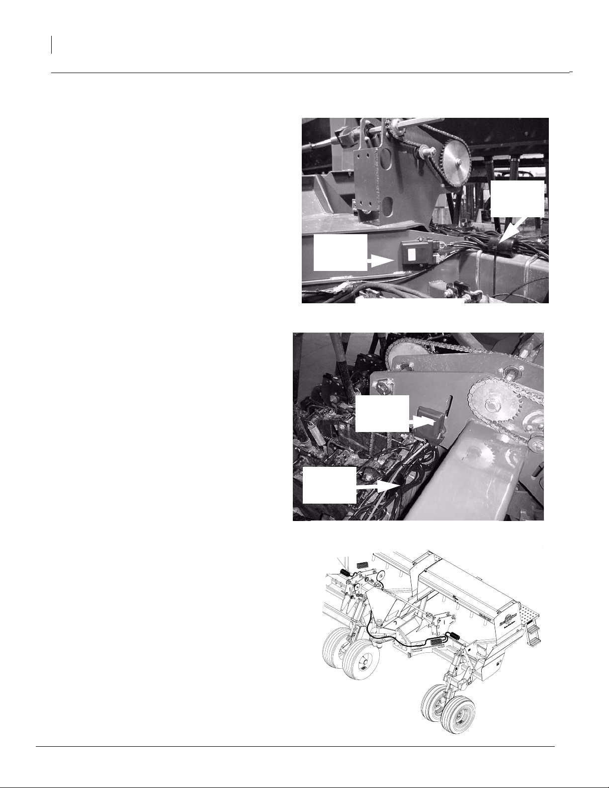
Refer to Figures 1 and 2
1. Mount one each ofthe materialflowmodules to
the wing frame asshownin figure 1.Mount one
each of the material flow modules to the drive
system frame as shown in figure 2.
NOTE:If there areno predrilled holes in theframeuse the
templates provided, mark and drill 5/16” holes for mounting modules. (Pages 9 & 10
2. Place the harness wire bundle onthe frame by
the material flow module.Connect the wire extensions to the openers starting at the left side
of the drill in numerical order. Wire extension
number 1 with first openeron the left. Continue
in the same manner until allwire extensionsare
connected.Fastentheharnesstotheframewith
cable ties as shown in figures 1 and 2.
)
Material
Flow
Module
Great Plains Mfg., Inc.
Harness
Harness
Wire
Wire
Bundle
Bundle
3. Connect black and gray colored leads into the
material flowmodules. Inlets are color coded.
Black to blackand gray to gray.
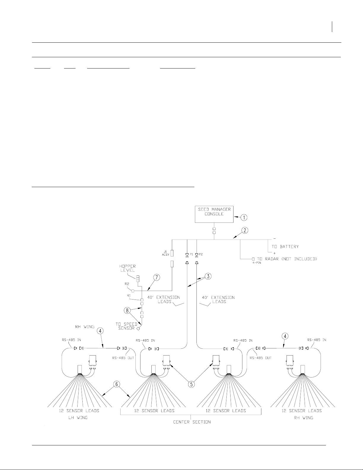
4. Referto Figure 3.Attach sensor lead marked IN
from the wing frame harness to the 15’ smart
sensor extension wire.Route the 15’ extension
using the same path as the openerlift hoses allowing the same slack at the drill toolbar pivots
as the other hoses. Connect this extension to
the center frame harness lead marked OUT.
Usecabletiesto secure the wires in place.Mark
these extensions P-1 and P-2 for further reference.
5. Assemble two of the 20’seed smart extensions
together then attach them to the center frame
harness sensor lead marked IN. Route the 20’
extensions through the tongue tube up to the
tractor.The left extensions will connect to Port 1
and the right extensions will connect to port 2.
NOTE: Left-hand side of drill is shown in figures. Lefthand and Right-hand sides on the Drill are done in the
same manner. The left side will go to port 1 and the right
side to port 2.
Figure 1 Wing Frame
Material
Flow
Module
Harness
Wire
Bundle
Figure 2 Center- Drive System Frame
19217
19218
6. Referto page3 for a detailed listing of partsand
schematics for this particular monitor system.
7. For console assembly, speed sensor and other
schematics illustrations refer to the DJ manual
found in the monitor system package.
8. Refer to page 8 for speed sensor instructions if
sensor is being used.
NOTE: J1 accessory harness and two 20’ extensions are not used if speed sensor on drills is not
Routing for wire Harness
used.
196-264m 4/8/2004
Figure 3
19255
Page 3
Great Plains Mfg., Inc.
833-232C cont.
Ref # Qty Part Number Description
1. 1 466820010S3 Seed Manager Console*
2. 1 466820131S1 J1 Harness 1-36 Rows (485B)
3. 2 466820517S3 40’ SeedSmart Sensor Ext.
4. 2 466820513S3 15’ SeedSmart Sensor Ext.
5. 4 467751020S1 Material FlowModule
6. 4 467751041S1 Material FlowModule Harness 12
7. 1 466820640S1 J1 Accessory Harness
8. 2 466820833S1 20’ ReedSW/RLCTNC SensorExt
*NOTE: Refer to DJ manual for Console installation.
30P 48 Row 7.5" Spacing Monitor System Schematics
Installation Instructions
3
Note: For further schematic illustration, refer to the DJ manual supplied in the Monitor System Package.
4/8/2004
19228
196-264m
Page 4

Monitor Systems Option
4
Assembly Instructions f or 833-233C 10 inc h Ro w Spacing
Great Plains Mfg., Inc.
Refer to Figure 4
1. Mount the end of the 16 row harness to the lefthand wing frame as shown in figure 4. Route the
wire extension acrossthe frame. Usethe cable ties
provided to fasten the harness to the frame.
2. Mount the end of the 20 row harness to the righthand wing frame. Route usingthe samepath asthe
opener lift hosesallowing thesame slack at thedrill
toolbar pivots as the other hoses.
3. Connect the wire extensions to the openersstarting
atthe left side of the drillin numericalorder. Wire extension number 1 with first opener. Continue inthe
same manner until all wire extensions are connected. Fasten the wires downwith cable ties.
4. Attachsensorleadfromharness(Left-hand 348") to
the J1 Harness. Attachsensor leadfrom harness
(Right-hand 348") to the J2 Harness.These leads
willthenconnecttotheconsole.Referto DJ manual.
NOTE:Left-hand side ofdrillareshownin figures.
Left-hand and Right-hand sides on the Drill are
done in the samemanner. The left side will go to
J1 and the right side to J 2.
5. Refer to page 5 fora detailedlisting ofparts and
schematics for this particular monitor system.
6. For console assembly, speedsensor, and other
schematicsillustrations referto theDJmanualfound
in the monitor system package.
7. Refer to page 8 for speed sensorinstructions if sensor is being used
Figure 4
Routing
196-264m 4/8/2004
19257
Page 5

Great Plains Mfg., Inc.
Installation Instructions
833-233C cont.
Ref # Qty Part Number Description
1. 1 466820010S1 Seed ManagerConsole*
2. 1 466820121S1 J1 Harness
3. 1 466820141S1 J2 Harness.
4. 1 458411340 16 Row Harness
5. 1 4584113411 20 Row Harness
6. 1 110001103 Manual (included in 466820010S1)
7. 1 110011161 Ver. 5.0 Addendum (included in 466820010S1)
8. 1 110011178 Ver 6.0 Addendum (included in 466820010S1)
*NOTE: Refer to DJ manual for Console installation.
5
30P 46 Row 10" Spacing Monitor System Schematics
Note: For further schematic illustration, refer to the DJ manual supplied in the Monitor System Package.
4/8/2004
19229
196-264m
Page 6

Great Plains Mfg., Inc.
Monitor Systems Option
6
Assembly Instructions for 833-234C Harness f or 15 inch Row Spacing,
Twin Row only Machines and 833-169C Console.
Refer to Figure 5
1. Mount one end of the harness to the frame as
shown in figure 5. Route the wire extension using
the same path as theopener lift hoses allowing the
same slack at the drill toolbar pivots as the other
hoses.Use the cable ties provided to fasten the harness to the frame.
2. Mount the center module to the frame. Route the
wire extensionthrough the tongue tube as shown in
figure 2.
3. Connectthe wire extensionstotheopeners starting
attheleftsideof the drill in numerical order.Wireextension number 1 with first opener on the left. Continue in the same manner until all wire extensions
are connected. Fasten the wires down with cable
ties.
4. Attach sensor lead(380) from thecenter module to
the console in your tractor.
5. Refer to page 7 fora detailedlisting ofparts and
schematics for this particular monitor system.
6. For console assembly, speedsensor andother
schematics illustrations refer to the DJ manual
found in the monitor system package.
7. Referto page 8for speed sensorinstructions if sensor is being used
19257
196-264m 4/8/2004
Figure 5
Page 7

Great Plains Mfg., Inc.
Installation Instructions
833-234C cont.
Ref# Qty Part Number Description
1. 1 45814-1360S1 30P 24 Row 15/TR Monitor Harness
2. 1 833-169C DJ-45841-0720 PM3000 Seed Monitor Console
30P 24 Row 15/TR Monitor Harness Schematics
7
ote: For further schematic illustration, refer to the DJ manual supplied in the Monitor System Package.
4/8/2004
19230
196-264m
Page 8

Monitor Systems Option
8
Refer to Figure 1
1. Assemble mounting bracket (1)and sensor
bracket(2) together using hardwaresupplied
in kit. Assemble mounting bracket tothe inside of the plate on the left gauge wheel. Install the Dickey-john magnetic pickup sensor
(3) to the sensor mounting bracket.
2. Loosen fasteners at bearings (4) on either
side of the contact wheel pivot shaft (5). Slide
pickupdisk (6)ontoshaft usinglockcollars(7)
on either side to hold in place.
Refer to Figure 2
3. Tighten bearings back down. Alignsensor
and pickup disk with centerline. Be sure to
tighten set screws after alignment is done.
4. Connect sensor to wire harness sensor extension.
Great Plains Mfg., Inc.
Templates for 833-232C 7 1/2 Row Spacing Material Flow Module
5. Set initial distance between sensor and pickupdisk at 0.040 inch. This may need to be adjusted up or down as necessary.
6. Figure 3 shows routing for wire harness.
Refer to the DICKEY-john Installation and
Operating Manual for further instructions.
Centerline
Figure 1
19286
Figure 2
Routing of Wire Harness
196-264m 4/8/2004
19284Figure 3
Page 9

Great Plains Mfg., Inc.
Templates for 833-232C 7 1/2 Row Spacing Material Flow Module
Installation Instructions
19288
9
4/8/2004
196-264m
Page 10

Monitor Systems Option
10
Great Plains Mfg., Inc.
Templates for 833-232C 7 1/2 Row Spacing Material Flow Module
19289
196-264m 4/8/2004
 Loading...