

Page 1
Great Plains Mfg., Inc.
Installation Instructions
No-Till and
No-Till Precision Seeding System
Veris Drive Option
Used with:
• 3N-3010P and 3N-3020P
• 3N-3010 and 3N-3020
General Information
When you see this symbol, the subsequent instructions and
warnings areserious- follow without exception. Your life and
!
!
the lives of others depend on it!
These instructions explain how to install theVeris
Drive Option. TheVeris Drive isa precision popu-
lation controller which uses a hydraulic drive to
accurately drive the metering system or the feeder cups.
These instructions apply to:
120-298A Veris Drive Option
Manual Update
Refer to the 30 No-Till or the 30P No-Till operator’s manual for detailedinformation on safely
operating, adjusting, troubleshooting and maintaining the Veris Drive. Refer to the parts manual
for part identification.
196-248M Operator’sManual
196-248P Parts Manual
196-366M Operator’sManual
196-366P Parts Manual
Before You Start
Page9is a detailed listing ofpartsincluded in the
Veris DriveOption package. Usethis list to inventory parts received.
Tools Required
• Basic Hand Tools
Definitions
Right-hand and left-hand as used in this manual
are determined by facing the direction the
machine will travel while in use unless otherwise
stated.
© Copyright 2002 Printed
3/26/2003
120-301M
Page 2

Veris Drive Option
2
Assembly Instructions
!
Before installing the Precision Population Controller
on the seeding system, besure that the unit isproperly
supported to avoid injury during installation.
CAUTION!
Great Plains Mfg., Inc.
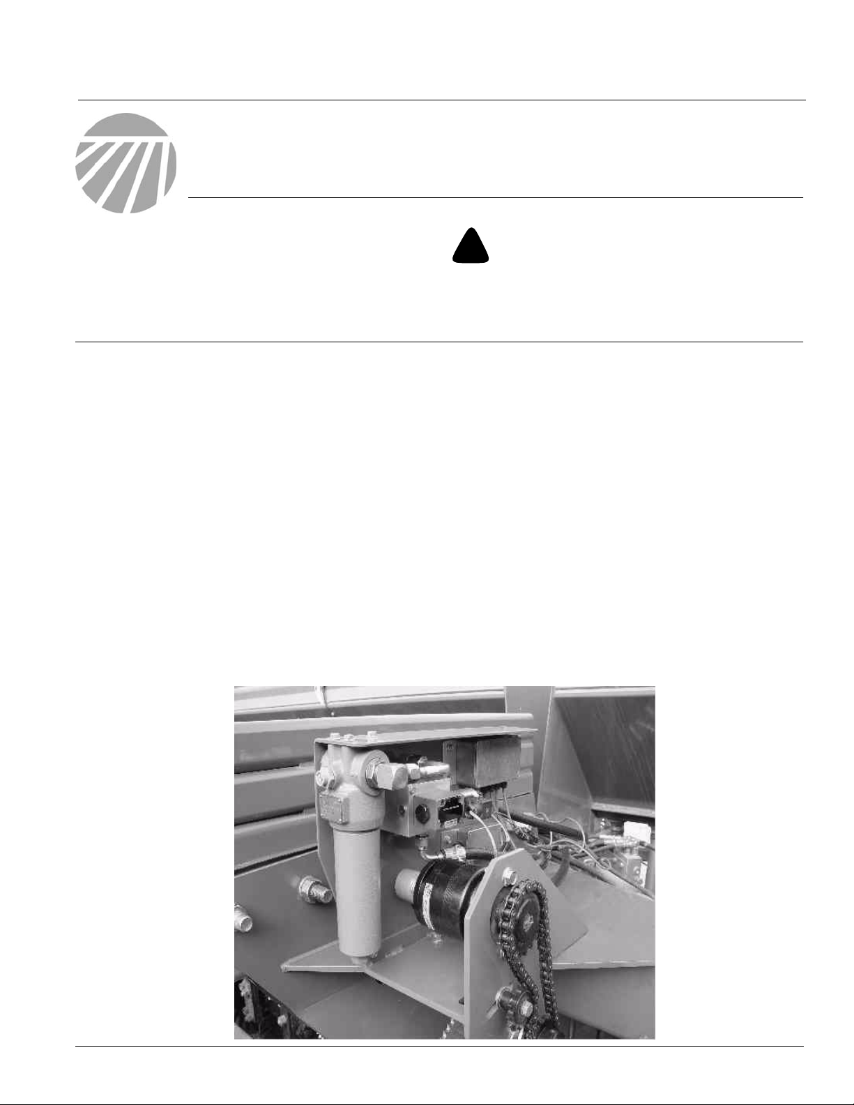
Refer to Figure 1
1. Remove contact wheel drive chains on both
sides of the unit.
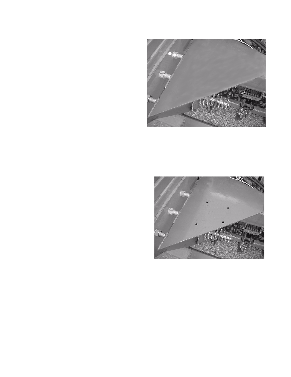
Refer to Figure 2
2. Remove range drivechains onboth sidesof
the unit.
Contact Drive Wheel
Chain Removed
Drive Chain Removed
Range Chain
Figure 1
20033
Figure 2
Range Drive Chain
Refer to Figure 3
3. Driveout roll pins from drivecouplers on both
ends of the pivot shaft. Slide shaft couplers
toward the center and slide shaft through
tongue away from the left-hand drive.
Figure 3
Pivot Shaft and Coupler
120-301M 4/8/2004
Shaft Coupler
Pivot Shaft
20034
20035
Page 3
Great Plains Mfg., Inc.
Refer to Figure 4
4. To mark and drill mounting holes for the controller/motor kit, usethe dimensionssupplied
on page 8. Mark the holes on the left-hand
tonguegusset onthemainframe andcarefully
drill all four holes.
Note: It is important that you carefully mark and
drill these mounting holes.The lower portion of
the drive mount houses the carrierbearingfor the
pivot shaft. Misalignment will cause operational
problems.
Installation Instructions
Place Template
Here
Figure 4
Hole Chart
3
20198
Refer to Figure 5
5. Drillholeswitheithera17/32”or 9/16” drillbit.
17/32”
Holes
Figure 5
Left-hand Gusset
20036
4/8/2004
120-301M
Page 4

Veris Drive Option
4
Great Plains Mfg., Inc.
Refer to Figure 6
6. Mount controller/motor kit to the gusset with
four flanged 1/2” x 1 1/4” bolts and 1/2”
flanged lock nuts, do not tighten at this time.
Leavehydraulichosesandharness coiled until later in the assembly.
Refer to Figure 7
Mounting
Bolts
Controller/Motor Kit
Figure 6
Controller/Motor
Pivot Shaft
20037
7. Slide the pivot shaft towardsthe installed
drivemountuntilshaftisafewinches through
the bearing hanger. Slide on one lock collar,
bearing and bearing flangettes. Installthe 19
tooth sprocket and second lockcollar. Slide
shaft back into position, then slide couplers
backinto position. Check to see if shaft is centered in the bearinghanger opening. Loosely
attach bearings flangettes, then tighten the
four mounting bolts on the controller/motor.
Tighten bearing flangettes.
Note:Shaft should nowturnfreely byhand with no
bindingat the shaftcouplers.If thisisnotthe case,
the drivemount isnot properly positioned on the
gusset. Tocorrect this, enlarge the mounting
holes to allow the mount to be moved forward or
backwardto properly alignthe mountwith the pivot shaft.
Once the mountis properlyaligned with the pivot
shaft,reinstall the shaft couplers with 1/4” x1 3/4”
bolts and 1/4” lock nuts.
Bearing
Figure 7
Pivot Shaft
Sprocket
Lock Collar
20038
120-301M 4/8/2004
Page 5

Great Plains Mfg., Inc.
Refer to Figure 8
8. Slide the firstlock collar installed on the pivot
shaft against the bearing and tighten. Slide
the 19 tooth sprocket installed on the pivot
shaft against the bearing. Slide the second
lock collar installedon the pivotshaft against
the sprocket and tighten.
9. Install chain idler and chain.
Note: In orderfor themotor tohavethe correct ratio to the seed metersyou must set therange and
the transmission sprockets.
Installation Instructions
Idler
Figure 8
Chain and Chain Idler
5
20039
Refer to Figure 9
10. For Precision drill:
Set the range sprockets with a 30 tooth
sprocketfor the driver, and a30 tooth sprocket for the driven, on bothsides of the unit.Reinstall chains and tighten the idlers.
11. For Feeder Cupdrill:
Set the range sprockets to drive type4 on
both sides of the unit. Reinstall chains and
tighten the idlers.
Refer to Figure 10
12. Setthe transmissionsprocketswitha28 tooth
sprocketfor the driver, and a25 tooth sprocket for the driven, on both sides of the unit.
Note: Be sure to set both the left-hand and righthand range and transmission sprockets. Once
they are set they will not need to be changed.
Note: For FeederCup drill there is no transmission sprocket change.
Figure 9
Range Sprockets
20040
4/8/2004
Figure 10
Transmission Sprockets
20041
120-301M
Page 6

Veris Drive Option
6
Refer to Figure 11
13. Removetheleft wheel from theleft-hand contactwheelshaftandslide the shaft to the right
allowing clearance forthe speedsensor disc
andsensorbracket.Install the sensor bracket
with one bearing onto the shaft. Install the
speed sensor disc with one lock collar on
each side. Do not tighten lock collars.
14. Remove the forward boltfrom theoutside
bearingandreplace it witha5/16" x 13/4"bolt
and 5/16" nut and tighten. Place the spacer
on the bolt then mount the sensor bracket on
the bolt. Secure bracket with a 5/16" nut.
15. Screw the sensor into thesensor mount until
there is a .030 clearance. Lock sensor in
place with the jam nut. Move the sensor disc
so it aligns with the sensor and secure it in
place with the lock collars. Route the cable
along the contact wheel arm and up to the
controller/motor mount. Repeat steps 13
through 15 to install the Verissensor and sensor bracket on the right-hand drive.
Lock Collars
Figure 11
Speed Sensor and Bracket
Left-Hand Side
Great Plains Mfg., Inc.
Seed Sensor
Speed Sensor
Sensor Disc
20042
16. Relocate the seed monitor speed sensor to
the bracket installed on the left-hand drive.
Properly adjustclearance. Tie bothcables to
the contact wheel arm, and make sure they
are routed to prevent pinching.
Note: You can not leave the seed monitor speed
sensor on the pivot shaft or the sensor will be
reading motor drivespeed instead offield speed.
It is not necessaryto movethe sensor disc for the
seedmonitor.Theseed monitorcanusethe same
sensor disc as the Veris sensor.
Note: After relocatingthe seed monitor speed
sensor it will be necessary to calibrate the
monitor. Refer to the DICKEY-john® manual
for monitor distance calibration instructions.
120-301M 4/8/2004
Page 7

Great Plains Mfg., Inc.
Refer to Figure 12
17. Connect sensor cable to short leads on sen-
sor module. Either cable can be connected to
either lead.
18. Uncoilhydraulichosesandmainharnessand
tie ends together. Feed a fish tape or a wire
fromthefront of thetongueandpullthe hoses
and cable through the maintongueand route
through the hose carrier on front of the
tongue.
19. Install the plastic hose label, P/N 817-348C,
to hose with “extension” symbol on the hose
runningtofilter (markedP)oncontrol module.
Use the yellow cable tieto identifythis asa
motor hose. Attach motor return hose
(marked T) on the side showing the “retract”
symbol.Run tie strapthroughnumber thatwill
correspond to the valve 2 through 4 that the
drive will be connected to.
Installation Instructions
Console
Sensor Module
Figure 12
Sensor Module
7
20043
Refer to Figure 13
20. Installthe console in a convenientlocation on
a side window glass. Make sure the glass is
clean.Moisten cups and press firmly ontothe
glass. To remove, pull tab on suction cup.
21. Connect power port adaptor cable to the ter-
minal on the console.
22. Route the power and communication cables
through the cab access hole and connect to
the appropriate terminals on the console.
Power Port
Adapter
Serial Cable
(for recipe input)
Figure 13
Control Console
Communication
Cable
19977
4/8/2004
120-301M
Page 8

Veris Drive Option
8
Great Plains Mfg., Inc.
120-301M 4/8/2004
Page 9

Great Plains Mfg., Inc.
120-298A PPC-30 Veris Vari-Rate Drive
Your kit includes:
Qty. Part No. Part Description
1 120-301M MANUAL INSTALL VERIS 30P
2 120-309D SENSOR DISC, 42T 5.3 DIA P
2 120-311D SENSOR U-MOUNT BRACKET
1 136-182D CHAIN RL #50 50 PITCHES
1 198-029D PARALLEL ARM PIVOT TUBE
6 402-025S LOCK COLLAR, 7/8 HEX W/ SET SCREWS
1 802-039C HHCS 1/2-13X3 GR5
3 802-159C HHCS 5/16-18X1 GR5
2 802-572C RHSNB 5/16-18X1 3/4 GR5
4 802-705C HHCS 5/16-18X5/8
4 803-011C NUT LOCK 5/16-18 PLT
1 803-069C NUT HEX SLOTTED 7/16-14 PLT
3 803-177C NUT HEX LOCK 5/16-18 FLG.
3 804-017C WASHER FLAT 1/2 USS PLT
4 804-036C WASHER FLAT 5/16 SAE PLT
1 808-006C SPKT 50B19 X 1 BORE
1 808-304C SPKT 50C19 X 7/8 HEX BORE
1 808-341C SPKT 50B13 IDLER
4 822-032C FLANGETTE 52 MST
2 822-119C BRG.7/8HEX BR 52MM SPHRICAL
2 822-175C FLANGETTE 52 3-BOLT PLT
1 822-195C BRG.7/8HEX 52MM SPHR OD PE
1 833-250C VERIS PPC-30 CONTROLLER
Installation Instructions
9
120-301M4/8/2004
 Loading...