

Page 1
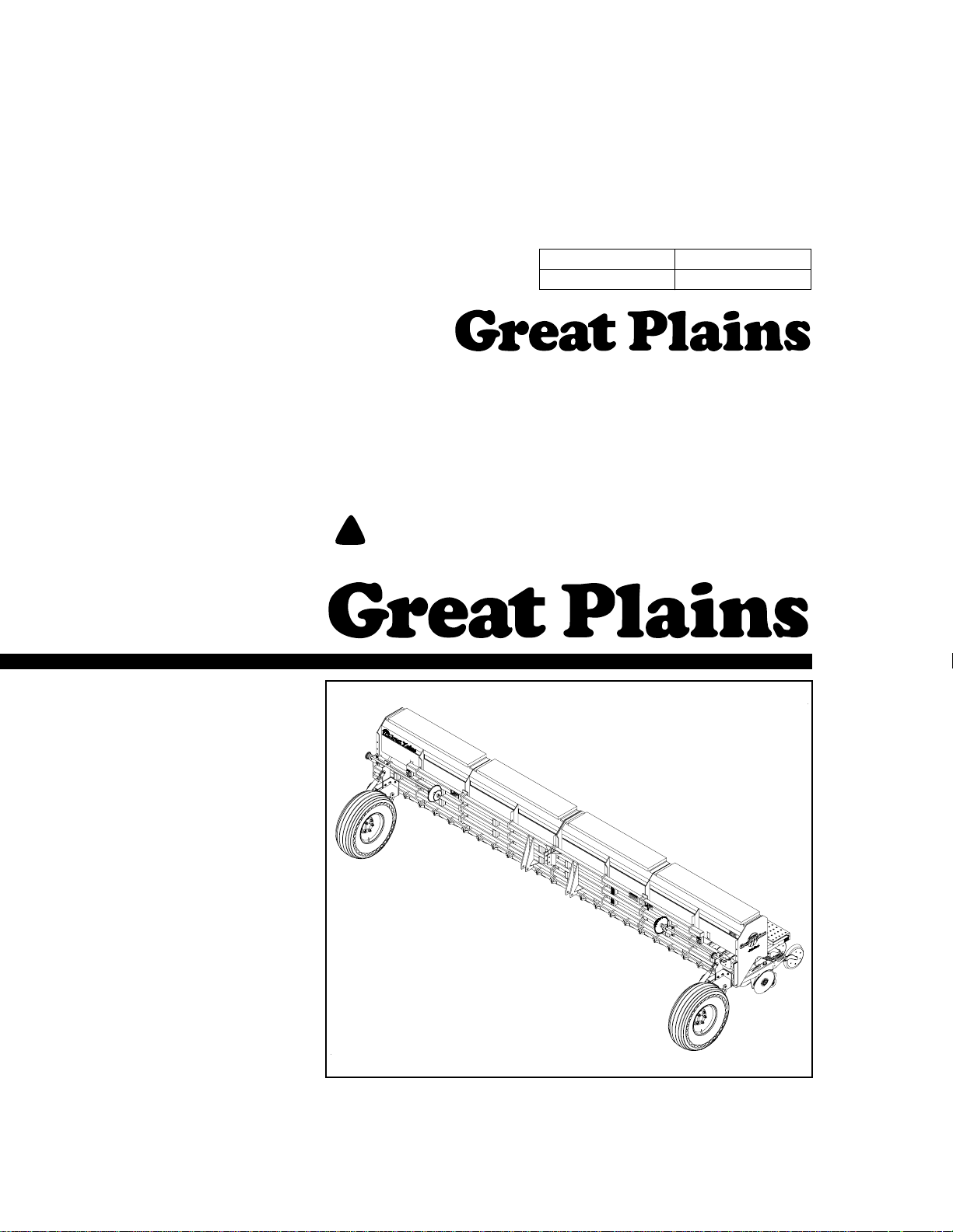
Operator’s Manual
2700 and 3000
Three-Point Drill
Model Serial No.
3PD27 and 2700 1316E+
3PD30 and 3000 1171S+
Manufacturing, Inc.
www.greatplainsmfg.com
Read the operator’s manual entirely. When you see this symbol, the subsequent in-
!
structions and warnings are serious - follow without exception. Your life and the lives of
others depend on it!
© Copyright 2010 Printed
9/9/2010
17883
Illustrations may show optional equipment not supplied with standard unit.
118-365M-A
Page 2

Table of Contents
Table of Contents
Great Plains Mfg., Inc.
Important Safety Information . . . . . . . . . . . . . . . . . 1
Safety Decals. . . . . . . . . . . . . . . . . . . . . . . . . . . . 4
Introduction . . . . . . . . . . . . . . . . . . . . . . . . . . . . . . . 7
Description of Unit . . . . . . . . . . . . . . . . . . . . . . . . 7
Intended Usage . . . . . . . . . . . . . . . . . . . . . . . 7
Using This Manual . . . . . . . . . . . . . . . . . . . . . . . . 7
Definitions . . . . . . . . . . . . . . . . . . . . . . . . . . . 7
Owner Assistance . . . . . . . . . . . . . . . . . . . . . . . . 7
Section 1 Preparation and Setup . . . . . . . . . . . . . . 8
Prestart Checklist. . . . . . . . . . . . . . . . . . . . . . . . . 8
Tractor Requirements . . . . . . . . . . . . . . . . . . . . . 8
Hitching Tractor to the Drill. . . . . . . . . . . . . . . . . . 8
Gauge-Wheel Adjustment . . . . . . . . . . . . . . . . . . 8
Bleeding Marker Hydraulics. . . . . . . . . . . . . . . . . 8
Section 2 Operating Instructions . . . . . . . . . . . . . . 9
Prestart Checklist. . . . . . . . . . . . . . . . . . . . . . . . . 9
Field Operation . . . . . . . . . . . . . . . . . . . . . . . . . . 9
Shaft Monitor Operation . . . . . . . . . . . . . . . . 9
Transporting . . . . . . . . . . . . . . . . . . . . . . . . . . . . . 9
Transporting with Markers . . . . . . . . . . . . . . . 9
Parking . . . . . . . . . . . . . . . . . . . . . . . . . . . . . . . . 10
Section 3 Adjustments . . . . . . . . . . . . . . . . . . . . . 11
Gauge-Wheel Adjustment . . . . . . . . . . . . . . . . . 11
Adjusting Seeding Depth . . . . . . . . . . . . . . . . . . 12
Press Wheels . . . . . . . . . . . . . . . . . . . . . . . 12
Down-Pressure Springs . . . . . . . . . . . . . . . 12
Bedded Irrigation . . . . . . . . . . . . . . . . . . . . . 12
Seeding Rate . . . . . . . . . . . . . . . . . . . . . . . . . . . 12
Small Seeds Attachment . . . . . . . . . . . . . . . 14
Seed Rate Charts (pounds per acre). . . . . . . . . 15
Small Seeds Attachment Seed Rate Chart . . . . 17
Marker Adjustments. . . . . . . . . . . . . . . . . . . . . . 18
Chain Adjustment. . . . . . . . . . . . . . . . . . . . . 18
Disk Adjustment . . . . . . . . . . . . . . . . . . . . . . 18
Speed Adjustment . . . . . . . . . . . . . . . . . . . . 19
Disk Scraper Adjustment . . . . . . . . . . . . . . . . . . 19
Seed-Lok™. . . . . . . . . . . . . . . . . . . . . . . . . . . . . 19
Section 4 Troubleshooting . . . . . . . . . . . . . . . . . . . 20
Section 5 Maintenance and Lubrication . . . . . . . . 22
General Maintenance . . . . . . . . . . . . . . . . . . . . . 22
Marker Maintenance . . . . . . . . . . . . . . . . . . 22
Storage . . . . . . . . . . . . . . . . . . . . . . . . . . . . . . . . 22
Lubrication . . . . . . . . . . . . . . . . . . . . . . . . . . . . . 22
Seed-Cup-Drive Sprocket . . . . . . . . . . . . . . 22
Drive Chains. . . . . . . . . . . . . . . . . . . . . . . . . 23
Drive Chains. . . . . . . . . . . . . . . . . . . . . . . . . 23
Jackshaft Bearings. . . . . . . . . . . . . . . . . . . . 23
Wheel Axles . . . . . . . . . . . . . . . . . . . . . . . . . 23
Marker Hinges . . . . . . . . . . . . . . . . . . . . . . . 24
Marker-Disk Bearings. . . . . . . . . . . . . . . . . . 24
Section 6 Options . . . . . . . . . . . . . . . . . . . . . . . . . . 25
Seed-Cup Plugs . . . . . . . . . . . . . . . . . . . . . . . . . 25
Markers. . . . . . . . . . . . . . . . . . . . . . . . . . . . . . . . 25
Seed-Lok™ Firming Wheels. . . . . . . . . . . . . . . . 25
Small Seeds Attachment . . . . . . . . . . . . . . . . . . 26
Steel Depth Bands . . . . . . . . . . . . . . . . . . . . . . . 26
Shaft Monitor . . . . . . . . . . . . . . . . . . . . . . . . . . . 26
Section 7 Specifications and Capacities . . . . . . . 27
Appendix . . . . . . . . . . . . . . . . . . . . . . . . . . . . . . . . . 29
Tire Inflation Chart . . . . . . . . . . . . . . . . . . . . . . . 29
Torque Values Chart for Common Bolt Sizes . . . 29
Warranty . . . . . . . . . . . . . . . . . . . . . . . . . . . . . . . 30
© Copyright 2010 All rights Reserved
Great Plains Manufacturing, Inc. provides this publication “as is” without warranty of any kind, either expressed or implied. While every precaution has been taken in the preparation
of this manual, Great Plains Manufacturing, Inc. assumes no responsibility for errors or omissions. Neither is any liability assumed for damages resulting from the use of the information contained herein. Great Plains Manufacturing, Inc. reserves the right to revise and improve its products as it sees fit. This publication describes the state of this product at the
time of its publication, and may not reflect the product in the future.
The following are trademarks of Great Plains Mfg., Inc.: Application Systems, Ausherman, Land Pride, Great Plains, Seed-Lok
All other brands and product names are trademarks or registered trademarks of their respective holders.
2700 and 3000 Three-Point Drill 118-365M-A 9/9/10
Great Plains Manufacturing, Incorporated Trademarks
Printed in the United States of America.
Page 3
Great Plains Mfg., Inc.
Important Safety Information
Important Safety Information
Be Aware of Signal Words
Signal words designate a degree or
level of hazard seriousness. The signal words are:
!
DANGER!
Indicates an imminently hazardous
situation which, if not avoided, will
result in death or serious injury. This
signal word is limited to the most
extreme situations, typically for
machine components that, for functional purposes, cannot be guarded.
!
WARNING!
Indicates a potentially hazardous situation which, if not avoided, could
result in death or serious injury, and
includes hazards that are exposed
when guards are removed. It may
also be used to alert against unsafe
practices.
!
CAUTION!
Indicates a potentially hazardous situation which, if not avoided, may
result in minor or moderate injury. It
may also be used to alert against
unsafe practices.
!
Keep Riders
Off Machinery
▲ Riders obstruct the operator’s
view. Riders could be struck by
foreign objects or thrown from the
machine.
▲ Never allow children to operate
equipment.
For Your Protection
▲ Thoroughly read and understand
Safety Decals, page 4. Read all
instructions noted on the decals.
OFF
Shutdown and Storage
▲ Lower machine to ground, put
tractor in park, turn off engine,
and remove the key.
▲ Detach and store implements in a
area where children normally do
not play. Secure implement by
using blocks and supports.
Handle
Chemicals Properly
▲ Wear protective clothing.
▲ Handle all chemicals with care.
▲ Follow instructions on container
label.
▲ Agricultural chemicals can be
dangerous. Improper use can
seriously injure persons, animals,
plants, soil, and property.
▲ Inhaling smoke from any type of
chemical fire is a serious health
hazard.
▲ Store or dispose of unused chem-
icals as specified by the chemical
manufacturer.
9/9/10
2700 and 3000 Three-Point Drill 118-365M-A
1
Page 4
Important Safety Information
Great Plains Mfg., Inc.
Use Safety
Lights and Devices
▲ Slow moving tractors, self-pro-
pelled equipment, and towed
implements can create a hazard
when driven on public roads. They
are difficult to see, especially at
night.
▲ Flashing warning lights and turn
signals are recommended whenever driving on public roads. Use
tractor lights and devices provided
with implement.
Transport
Machinery Safely
▲ Comply with state and local laws.
▲ Maximum transport speed for
implement is 20 mph. DO NOT
EXCEED. Never travel at a speed
which does not allow adequate
control of steering and stopping.
Some rough terrains require a
slower speed.
▲ Sudden braking can cause a
towed load to swerve and upset.
Reduce speed if towed load is not
equipped with brakes.
▲ Follow these weight ratios as a
guideline.
20 mph maximum when weight is
less than or equal to the weight of
tractor.
10 mph maximum when weight is
double the weight of tractor.
▲ IMPORTANT: Do not tow a load
that is more than double the
weight of tractor.
Use A Safety Chain
▲ A safety chain will help control
drawn machinery should it separate from the tractor drawbar.
▲ Use a chain with the strength
rating equal to or greater than
the gross weight of the towed
machinery.
▲ Attach the chain to the tractor
drawbar support or other specified anchor location. Allow only
enough slack in the chain to permit turning.
▲ Do not use safety chain for tow-
ing.
Practice Safe Maintenance
▲ Understand procedure before
doing work. Use proper tools and
equipment. Refer to “Mainte-
nance and Lubrication,” page
22, for additional information.
▲ Work in a clean, dry area.
▲ Lower the implement to the
ground, put tractor in park, turn off
engine, and remove key before
preforming maintenance.
▲ Allow implement to cool com-
pletely.
▲ Do not grease or oil implement
while it is in operation.
▲ Disk edges are sharp. Be careful
when working in this area.
▲ Disconnect battery ground cable
(-) before servicing or adjusting
electrical systems or before welding on implement.
▲ Inspect all parts. Make sure parts
are in good condition and installed
properly.
▲ Remove buildup of grease, oil or
debris.
▲ Remove all tools and unused
parts from implement before operation.
2700 and 3000 Three-Point Drill 118-365M-A 9/9/10
2
Page 5
Great Plains Mfg., Inc.
Important Safety Information
Prepare for Emergencies
▲ Be prepared if a fire starts.
▲ Keep a first aid kit and fire extin-
guisher handy.
▲ Keep emergency numbers for
doctor, ambulance, hospital and
fire department near phone.
911
Wear
Protective Equipment
▲ Protective clothing and equipment
should be worn.
▲ Wear clothing and equipment
appropriate for the job. Avoid
loose-fitting clothing.
▲ Prolonged exposure to loud noise
can cause hearing impairment or
hearing loss. Wear suitable hearing protection such as earmuffs or
earplugs.
▲ Operating equipment safely
requires the full attention of the
operator. Avoid wearing radio
headphones while operating
machinery.
Avoid High
Pressure Fluids Hazard
▲ Escaping fluid under pressure can
penetrate the skin causing serious
injury.
▲ Avoid the hazard by relieving
pressure before disconnecting
hydraulic lines.
▲ Use a piece of paper or card-
board, NOT BODY PARTS, to
check for suspected leaks.
▲ Wear protective gloves and safety
glasses or goggles when working
with hydraulic systems.
▲ If an accident occurs, see a doc-
tor immediately. Any fluid injected
into the skin must be surgically
removed within a few hours or
gangrene may result.
Safety at All Times
Thoroughly read and understand the
instructions given in this manual
before operation. Refer to Safety
Decals, page 4. Read all instructions
noted on the decals.
▲ Operator should be familiar with
all functions of the unit.
▲ Operate implement from the
driver’s seat only.
▲ Do not leave tractor or implement
unattended with engine running.
▲ Dismounting from a moving trac-
tor could cause serious injury or
death.
▲ Do not stand between the tractor
and implement during hitching.
▲ Keep hands, feet and clothing
away from power-driven parts.
▲ Wear snug fitting clothing to avoid
entanglement with moving parts.
▲ Watch out for wires, trees, etc.,
when raising implement. Make
sure all persons are clear of working area.
▲ Turning tractor too tight may
cause implement to ride up on
wheels. This could result in injury
or equipment damage.
Tire Safety
▲ Tire changing can be dangerous
and should be preformed by
trained personnel using the correct tools and equipment.
▲ When inflating tires, use a clip-on
chuck and extension hose long
enough to allow you to stand to
one side and NOT in front of or
over the tire assembly. Use a
safety cage if available.
▲ When removing and installing
wheels, use wheel-handling
equipment adequate for the
weight involved.
9/9/10
2700 and 3000 Three-Point Drill 118-365M-A
3
Page 6
Important Safety Information
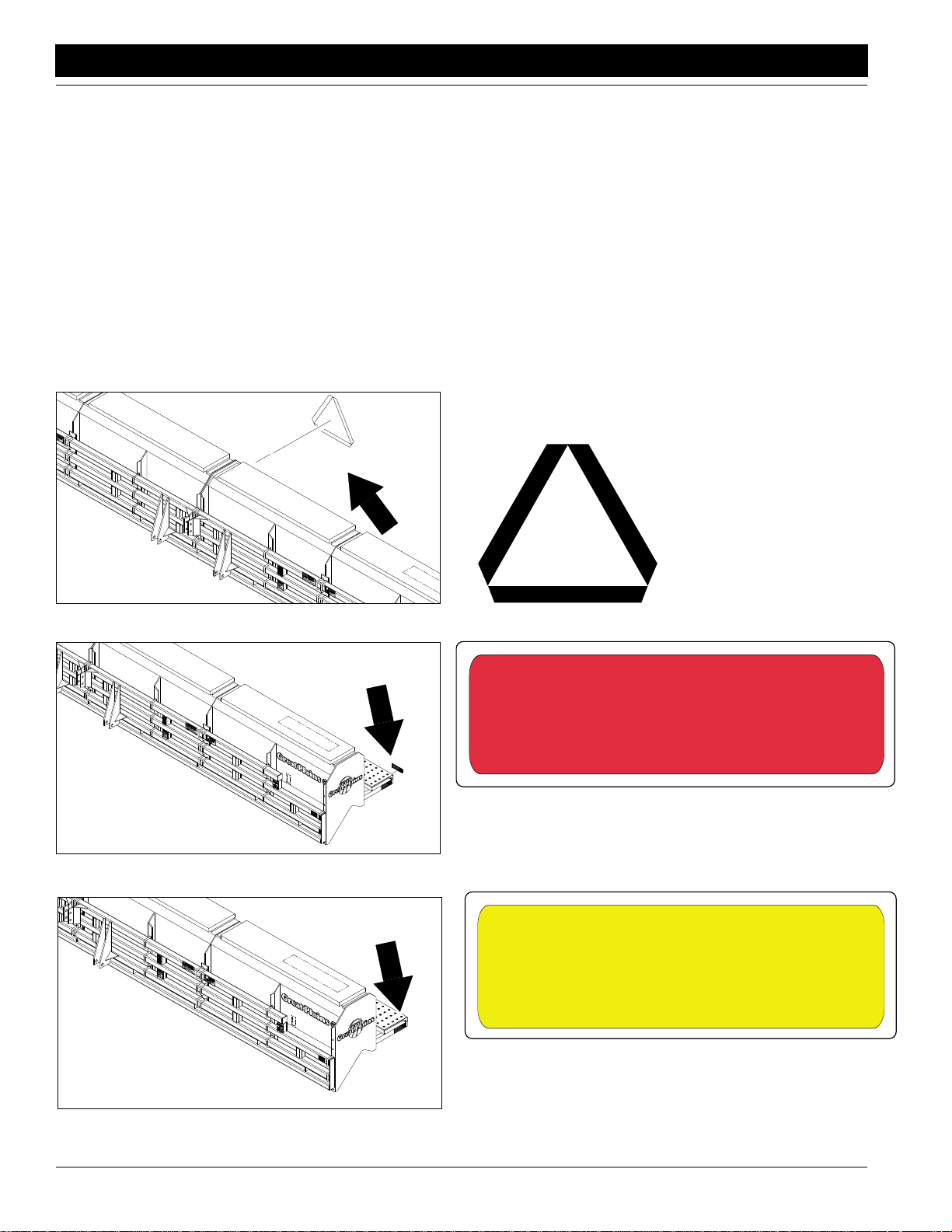
Safety Decals
Your implement comes equipped with all safety decals in place.
They were designed to help you safely operate your implement.
1. Read and follow decal directions.
2. Keep all safety decals clean and legible.
3. Replace all damaged or missing decals. Order new decals
from your Great Plains dealer. Refer to this section for
proper decal placement.
Great Plains Mfg., Inc.
4. When ordering new parts or components, also request corresponding safety decals.
5. To install new decals:
a. Clean the area on which the decal is to be placed.
b. Peel backing from decal. Press firmly on surface,
being careful not to cause air bubbles under decal.
17882
17894
818-003C
Slow Moving Vehicle Decal
838-266C
Red Reflectors
One on each walkboard;
two decals total
838-265C
17882
2700 and 3000 Three-Point Drill 118-365M-A 9/9/10
4
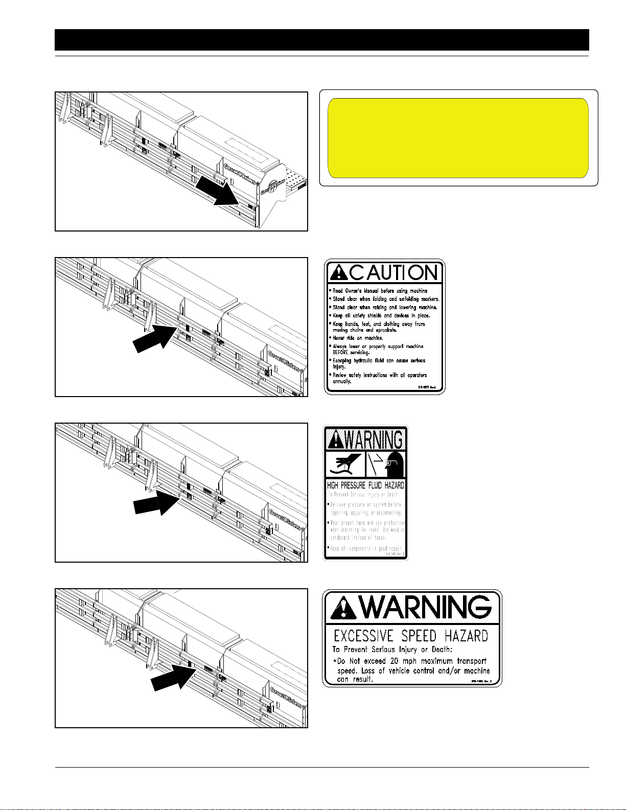
Amber Reflectors
Outside ends of each
walkboard
Page 7
Great Plains Mfg., Inc.
Important Safety Information
17882
838-265C
Amber Reflectors
Both ends of drill
17882
17882
818-587C
Caution Gen Safety 3-PT
818-339C
Warning High Pressure SML
17882
9/9/10
818-188C
Warning 20 MPH Transport
2700 and 3000 Three-Point Drill 118-365M-A
5
Page 8
Important Safety Information
17882
Great Plains Mfg., Inc.
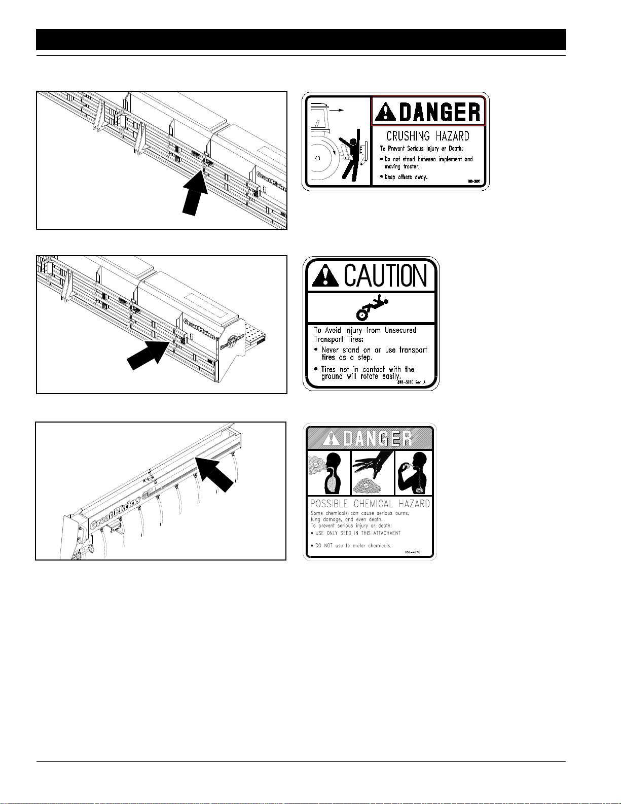
818-590C
Danger Crushing; both ends of drill, two decals total
17882
13734
818-389C
Caution Tires Not a Step
Both ends of drill, two decals total
838-467C
Possible Chemical Hazard
Small Seeds Box, Underside of Box Lid
2700 and 3000 Three-Point Drill 118-365M-A 9/9/10
6
Page 9
Great Plains Mfg., Inc.
Introduction
Introduction
Great Plains welcomes you to the growing family of new
product owners. This implement has been designed with
care and built by skilled workers using quality materials.
Proper assembly, maintenance and safe operating practices will help you get years of satisfactory use from this
machine.
Description of Unit
The 27- or 30-foot, 3-point drill is a seeding implement designed to be raised, lowered and towed with a three-point
tractor hitch. The drill is equipped with offset double-disk
openers mounted on the drill frame with straight arms. The
openers are staggered for easy residue flow. Down-pressure springs can be adjusted individually for each opener.
A T-handle adjustment on the depth-controlling press
wheels allows for easy depth adjustment. The seeding
rate can be adjusted from 2 to 240 pounds per acre.
When combined with the bedded irrigation option, the drill
can be used to seed in furrows and ridges simultaneously.
Intended Usage
This drill is intend for use in conventional- and some minimum-till applications.
Using This Manual
This manual is designed to help familiarize you with safety,
set-up, operation, adjustment, troubleshooting and maintenance. Read this manual and follow the recommendations to help ensure safe and efficient operation.
Fill out the warranty sheet with the dealer at the time of
purchase. Give the dealer the completed white copy and
send the pink copy to Great Plains. Keep your yellow copy
in the manual for use when corresponding with the dealer.
The information in this manual is current at printing. Some
parts may change to assure top performance.
Definitions
Right and left as used in this manual are determined by
facing the direction the machine will travel while in use unless otherwise stated.
IMPORTANT: A crucial point of information related to
the preceding topic. For safe and correct operation,
read and follow the directions provided before continuing.
Owner Assistance
If customer service or repair parts are needed contact
your Great Plains dealer. They have trained personnel,
parts and service equipment specially designed for Great
Plains products.
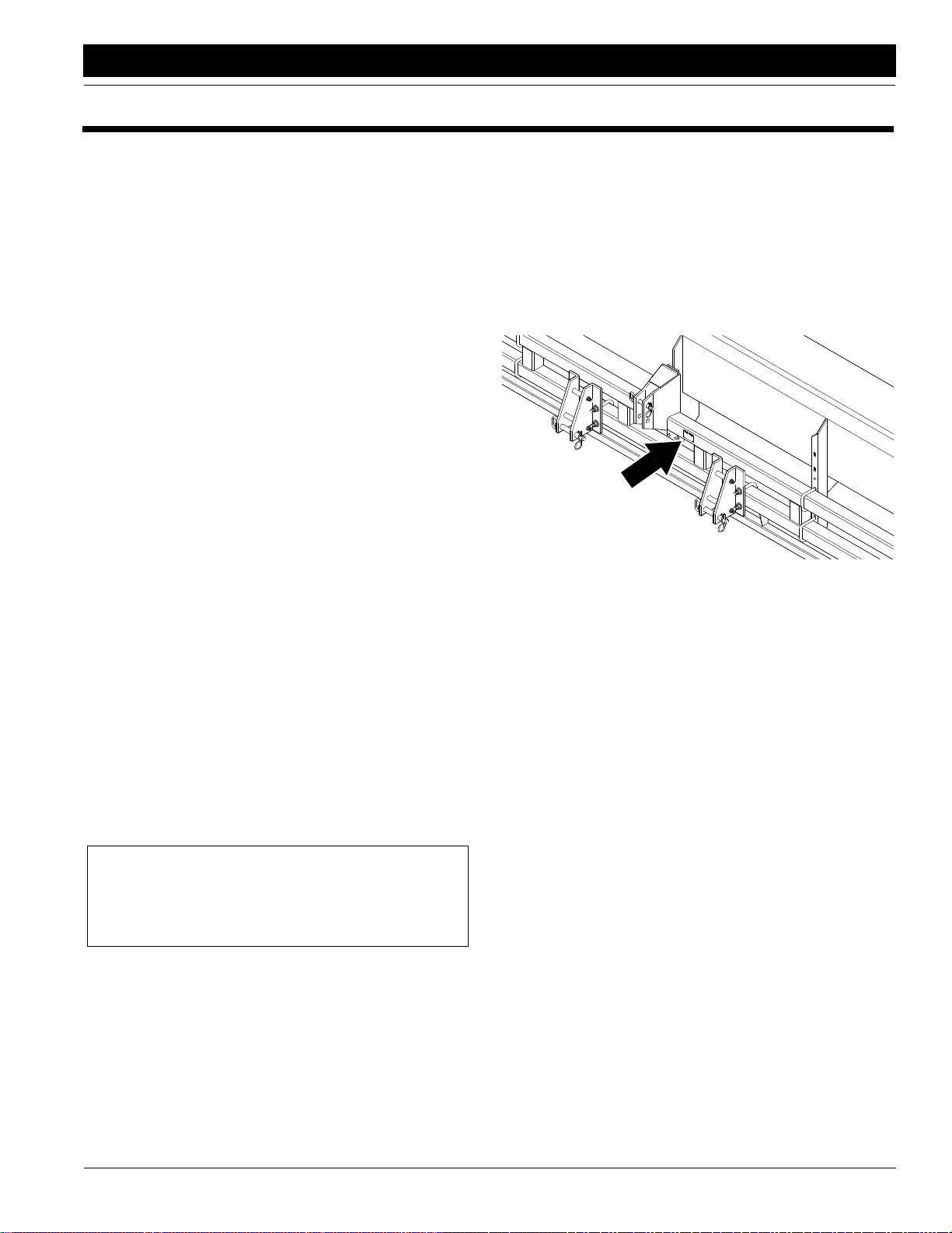
Your machine’s parts were specially designed and should
be replaced with Great Plains parts only. Always use the
serial and model number when ordering parts from your
Great Plains dealer. The serial number plate is located as
shown in Figure A.
16404
Figure A
Serial Number Plate
Your Great Plains dealer wants you to be satisfied with
your new machine. If you do not understand any part of
this manual or are not satisfied with the service received,
please take the following actions:
1. Discuss the matter with your dealer service manager.
Make sure they are aware of any problems so they can
assist you.
2. If you are still not satisfied, seek out the dealership
owner or general manager.
3. For further assistance, write to:
Product Support
Great Plains Mfg. Inc.
Service Department
P.O. Box 5060
Salina, KS 64702-5060
NOTE: Useful information related to the preceding topic.
9/9/10
2700 and 3000 Three-Point Drill 118-365M-A
7
Page 10
Section 1 Preparation and Setup
!
!
Section 1 Preparation and Setup
Great Plains Mfg., Inc.
This section will help you prepare your tractor and drill for
use. This section also includes instructions for bleeding
the optional marker hydraulics.
Prestart Checklist
1. Read and understand “Important Safety Information,” page 1.
2. Check that all working parts are moving freely, bolts
are tight, and cotter pins are spread.
3. Check that all grease fittings are in place and lubricated. Refer to Lubrication,“Maintenance and Lubrica-
tion,” page 22.
4. Check that all safety decals and reflectors are correctly located and legible. Replace if damaged. Refer to
Safety Decals,“Important Safety Information,” page
4.
5. Inflate tires to recommended pressure as listed on
Tire Inflation Chart,“Appendix,” page 29. Tighten
wheel bolts as specified on Torque Values Chart,“Ap-
pendix,” page 29.
Tractor Requirements
Your drill is designed and factory set for category III tractors.
Hitching Tractor to the Drill
Gauge-Wheel Adjustment
Gauge-wheel adjustments affect the operating height of
your drill, and drill height directly affects the working range
of the openers.The drill must be adjusted so your openers
can travel up and down and follow the ground contour.
Before using in the field, adjust your drill so the opener
mount tube runs 18 1/4 inches above ground. You likely
will need to make further adjustments later to compensate
for field conditions. Refer to Gauge-Wheel Adjustments,
“Adjustments,” page 11 for how to make gauge-wheel
adjustments.
Bleeding Marker Hydraulics
If you install or replace part of optional markers, you must
bleed air from the marker hydraulics. Your markers will not
fold properly with air in the hydraulic circuit.
WARNING!
Escaping fluid under pressure can have sufficient pressure to
penetrate the skin causing serious injury. Avoid the hazard by
relieving pressure before disconnecting hydraulic lines. Use a
piece of paper or cardboard, NOT BODY PARTS, to check for
leaks. Wear protective gloves and safety glasses or goggles
when working with hydraulic systems. If an accident occurs, see
a doctor immediately. Any fluid injected into the skin must be
surgically removed within a few hours or gangrene will result.
DANGER!
Do not place any body part between the tractor and drill during
hitching.
1. Raise or lower the 3-point links as needed.
2. Install the lower hitch pins.
3. Pin the top link to the drill and adjust so it remains
loose in normal field conditions.
4. Check that all three-point links are securely pinned,
then slowly raise the drill. Watch for cab interference.
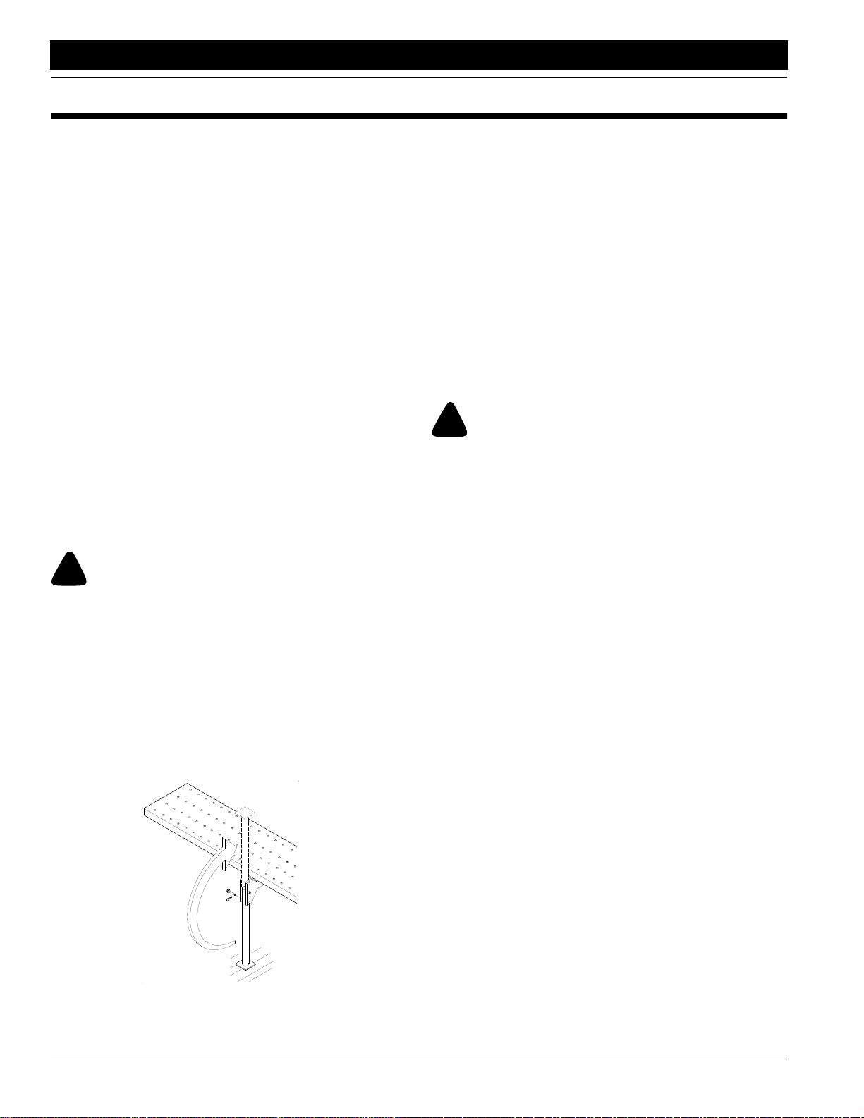
5. Unpin the parking stands as shown in Figure 1-1. Rotate the stands up into field position and repin.
12151
1. Be sure tractor hydraulic reservoir if full.
2. With the markers unfolded, crack the hydraulic hose
fittings at the base end of the cylinders. With your tractor at an idle speed, activate your tractor hydraulic
valve until oil seeps out around the hose ends. Retighten the fittings.
3. Repeat step 2 for the hose-end fittings at the rod end
of the cylinders.
4. Fold and unfold the markers slowly to work all the air
out of your marker hydraulics. Use caution when folding and unfolding the marker for the first time and
check for pinching and kinking of hoses.
Figure 1-1
Parking Stand
2700 and 3000 Three-Point Drill 118-365M-A 9/9/10
8
Page 11

Great Plains Mfg., Inc.
!
!
Section 2 Operating Instructions
Section 2 Operating Instructions
The following section will give you general operating procedures. Experience, machine familiarity and thefollowing
information will lead to efficient operation and good working habits. Always operate farm machinery with safety in
mind.
Prestart Checklist
1. Carefully read “Important Safety Information,” page
1.
2. Lubricate the drill as indicated under Lubrication,
“Maintenance and Lubrication,” page 22.
3. Check all tires for proper inflation as indicated on Tire
Inflation Chart,“Appendix,” page 29.
4. Check all bolts, pins and fasteners. Torque as specified on Torque Values Chart,“Appendix,” page 29.
5. Check the drill for worn or damaged parts. Repair or
replace them before going to the field.
6. Check hydraulic hoses, fittings and cylinders for leaks.
Repair or replace them before going to the field.
7. Check disk scrapers for proper adjustment. Refer to
Disk Scraper Adjustment,“Adjustments,” page 19.
8. Rotate both gauge wheels to see that seed cups and
drive are working properly and free from foreign material.
Field Operation
CAUTION!
Do not allow anyone to ride on the drill.
1. Hitch the drill to a suitable tractor before filling the drill.
Refer to Tractor Requirements and Hitching Tractor to
Drill,“Preparation and Setup,” page 8. Adjust the top
link so it remains loose in normal drilling conditions.
2. Set and calibrate the seeding rate as explained under
Seeding Rate,“Adjustments,” page 12.
3. Load box with clean seed.
4. Record the acremeter readout. Subtract the initial
reading from later readings to determine acres drilled.
5. Check that the seed-cup-door handles are set the
same across the drill. Refer to Seeding Rate,“Adjust-
ments,” page 12.
NOTE: If you notice excessive cracking on large seeds,
adjust all seed-cup doors to a wider setting. Use the widest setting for seed-cup clean out only.
6. Lift the drill out of the ground when turning at end of
the field and for other short turns. Do not back up with
openers in ground. If you do, check all openers for
clogging.
Shaft Monitor Operation
To operate the optional shaft monitor, turn system on by
activating on-off switch on monitor head. If the seed-cup
shaft stops for 20 seconds or more, an alarm will sound
and the light on the monitor will flash.
The 20-second delay is to prevent nuisance alarms when
turning at the end of the field. If a failure does occur and
the alarm sounds, remember you have traveled for 30
seconds without planting.
Transporting
WARNING!
Never tow the drill faster than 20 mph.
You can transport the drill with a full box of grain, but it is
not recommended. The increased weight will make steering more difficult and increase the risk of road accidents.
To maintain steering control, you may need to add ballast
to your tractor front end. Refer to your tractor operator’s
manual for the amount of ballast required.
Before transporting the drill, check the following.
1. Check that all 3-point hitch links are securely pinned
to the tractor.
2. Comply with all federal, state and local laws when
traveling on public roads.
3. Remember that the drill is wider than the tractor. Always allow for drill clearance.
Transporting with Markers
Always transport the drill with the markers folded. Check
that the second marker section rests securely on the
transport carrier. If it does not, refer to Marker Adjust-
ments,“Adjustments,” page 19 for transport carrier ad-
justments.
9/9/10
2700 and 3000 Three-Point Drill 118-365M-A
9
Page 12

Section 2 Operating Instructions
Parking
Unhitching the drill while the box is loaded is not recommended. Empty the box if possible. See Storage,“Mainte-
nance and Lubrication,” page 22 for additional
information on the long-term storage.
1. Park on a level, solid area.
2. Unpin and rotate the parking stands down into the
parking position. Replace pins as shown in Figure 2. If
the ground is soft, place a board under the parking
stand to increase ground contact area.
Great Plains Mfg., Inc.
3. Lower the drill to the ground.
4. Extend or retract the top link until the top 3-point pin is
free. Remove the pin.
5. Remove pins from the lower links.
16504
Figure 2
Parking Stand
2700 and 3000 Three-Point Drill 118-365M-A 9/9/10
10
Page 13

Great Plains Mfg., Inc.
Section 3 Adjustments
Section 3 Adjustments
Gauge-Wheel Adjustment
Gauge-wheel adjustments affect the operating height of
your drill, and drill height directly affects the working range
of the openers. The drill must be adjusted so your openers
can travel up and down and follow the ground contour. Initially adjust the gauge wheels so the bottom of the opener
mounting tube runs 18 1/4 inches above ground.
To adjust drill height:
1. Loosen the jam nut near the bottom clevis of each
gauge-wheel turnbuckle. Refer to Figure 3-1.
10548
Figure 3-2
Normal Spring Rod Setting, Drill Level
IMPORTANT: Do not use the links to adjust opener
depth. To achieve desired seeding depth, refer to Seed-
ing Depth, “Adjustments,” page 12.
10546
Figure 3-1
Gauge Wheel Turnbuckle
2. Bolt the upper clevis in the upper mounting hole.
3. Set the turnbuckle length. Turn the turnbuckle to
shorten or lengthen as necessary. Initially set the
length to 20 3/8 inches between pin centers to
achieve the 18 1/4-inch dimension mentioned above.
When adjusting the turnbuckle, remember:
•Lengthening the turnbuckle raises the drill and allows
less downward float of the openers.
•Shortening the turnbuckle lowers the drill and allows
less upward float of the openers.
NOTE: Remember that lowering the drillincreases the risk
of opener damage on rocks or obstructions.
4. After adjusting both turnbuckles, be certain they are
the same length, then tighten the jam nuts.
5. After setting the turnbuckles, level the drill with the top
hitch link. When the drill is level, the gap between the
spring-rod casting and the cross bolt will be about 2
inches. See Figure 3-2. This is a general dimension
that will vary with the amount of down pressure required for your planting conditions.
For some drill applications, you may want to equip your
drill with two spring-loaded links (part number 120-106A)
or a slotted link (part number 120-171A). Mount the links
in the top hole of the gauge wheel bracket as shown in Figure 3-3. You do not need to adjust the spring-loaded or
slotted links.
10547
Figure 3-3
Spring-Loaded Links For No-Till Drilling
9/9/10
2700 and 3000 Three-Point Drill 118-365M-A
11
Page 14

Section 3 Adjustments
Great Plains Mfg., Inc.
Adjusting Seeding Depth
Your drill is designed to run level to the ground when lowered into seeding position. You may need to make minor
adjustments to achieve desired seeding depth.
Press Wheels
Opener depth is controlled by the height of its press wheel.
Changing the height of the press wheel automatically
changes the seeding depth of the opener.
To adjust press-wheel height, lift up on the T-handle and
slide it forward or back. Refer to Figure 3-4.
12100
Figure 3-4
Press Wheel Adjustment
Down-Pressure Springs
Each opener can be adjusted individually for increased or
decreased down pressure. Increased down pressure aids
opener penetration in hard soils and tire tracks. Decreased down pressure may prevent openers from plugging in wet soil.
To adjust opener down pressure, remove the W clip at the
bottom of the spring shown in Figure 3-5. Place the clip in
a higher spring-rod hole for increased pressure. Place the
clip in a lower hole for decreased pressure. If an opener is
running too deep at the lowest pressure setting, the W clip
can be removed completely.
Bedded Irrigation
If your drill is outfitted with the bedded irrigation option,
you can adjust the height of openers that run in irrigation
furrows.
When running the drill in a level field, mount the openers in
the top hole (1).
To lower the openers for irrigation furrows, move the opener pivot bolt (2) to a lower hole in the opener mount. Lowering the pivot bolt one hole lowers the opener body 2 1/2
inches.
1
2
16766
Figure 3-6
Bedded Irrigation
Seeding Rate
Calibrating the seeding rate requires four steps: arranging
the drive sprockets, setting the seed-rate adjustment handle, positioning the seed-cup door, and checking the seeding rate.
Refer to the seed-rate charts starting on page 15. These
charts list the proper sprocket sizes and seed-rate-handle
settings for various seeds and seeding rates.
The seed-rate charts are based on cleaned, untreated
seed of average size and test weight. The rates are based
on 9.5L x 15 rib implement tires. Many factors will affect
seeding rates including foreign material, seed treatment,
seed size, field conditions, tire pressure and test weight.
Minor adjustments likely will be needed. Set and check the
seeding rate using the procedures below, then re-adjust
the rate as necessary.
Before setting the seeding rate, rotate the drive gauge
wheel to see that seed cups and drive are working properly and free from foreign material.
Minimum Pressure
12102
Figure 3-5
Individual Opener Spring Adjustment
2700 and 3000 Three-Point Drill 118-365M-A 9/9/10
12
Maximum Pressure
12103
Page 15

Great Plains Mfg., Inc.
Section 3 Adjustments
1. Change Drive Sprockets
Refer to the seed-rate charts for the correct drive
type–1, 1A, 2 or 2A. Figure 3-7 shows the sprocket arrangement for each drive type.
c. To change the jackshaft sprocket shown in Figure
3-9, remove the set screws and slide the sprockets so the correct-sized sprockets are aligned.
Reinsert set screws.
16412
Figure 3-9
Jackshaft Sprocket
d. Shorten or lengthen chains as necessary and re-
install chains. Be sure chain is installed with the
chain connector link retainer towards the centerline and the clip opening (split end) is facing the
opposite way of the chain travel. Move the idler
arms into chains. See Figure 3-10 for correct
chain slack.
16400
Figure 3-7
Drive Types
To change the drive type:
a. Loosen the idler-arm bolts and remove chains.
b. To change the double speed-change sprocket
shown in Figure 3-8, remove nut and turn sprocket
over.
Idler
Spr
oc
ket
1/2
In.
3/4
In.
Figure 3-10
Chain Slack
2. Set Seed-Rate Handle
The position the handle for each drill box to the setting
indicated on the chart. One handle is shown in Figure
3-11. To adjust the handles, loosen the wing nut under
the handles and slide until the indicator lines up with
the correct setting.
9/9/10
Idler
16409
Figure 3-8
Double Speed-Change Sprocket
Figure 3-11
Seed-Rate Handle
2700 and 3000 Three-Point Drill 118-365M-A
12927
13
Page 16

Section 3 Adjustments
Great Plains Mfg., Inc.
3. Position Seed-Cup Doors
For wheat and other small seeds. move the seed-cupdoor handles to the highest position. For soybeans
and other large seeds, lower the handles to the second position. If excessive seed cracking occurs, lower
the handles to the third position. Move the handles to
the fourth, wide-open position for seed-cup clean out.
Make sure all handles are in the same position before
drilling.
Figure 3-12
Seed-Cup-Door Handle
4. Check Seeding Rate
a. Record the weight of an empty container large
enough to hold the seed metered for one acre.
b. Place several pounds of seed over three seed
cups on an outside end of the drill box. Pull the
seed tubes off these three openers.
c. Raise the drill off the ground.
d. Turn the gauge wheel a few turns to fill the cups
with seed. Turn wheel until seed drops to the
ground from all three cups.
e. Place a container under the three seed tubes to
gather the seed as it is metered.
13867
f. Turn the drive gauge wheel until one acre has
been tallied on the acremeter (200 rotations on
a 27-foot drill or 182 rotations on a 30-foot drill).
Check that the three seed cups have plenty of
seed coming into them.
g. Weigh the metered seed. Subtract the initial
weight of the empty container. Divide by three
for the amount metered by each seed cup, then
multiply by the number of drill openers for the
pounds-per-acre seeding rate. If this figure is
different than desired, adjust the seed-rate handle and recheck the rate.
NOTE: If your results vary greatly from the charts, you
may want to repeat the calibration procedure.
When satisfied with the rate, set the same seeding rate
on the opposite drill box by repeating steps 1 through 3.
Small Seeds Attachment
To calibrate the seeding rate on the optional small seeds
attachment, follow these steps.
1. Refer to Figure 3-13 for the proper small-seeds
sprocket arrangement given different drive types on
the main drill box. Arrange the sprockets on the
small-seeds attachment according to which drive
type you will use on the main drill box.
NOTE: For accurate metering on the small seeds attachment, the main drill box sprockets must be set to
drive type 1, 2 or 2A.
2. Set the seed-rate adjustment handle on the small
seeds attachment as indicated by the chart on
Small Seeds Attachment Seed Rate Chart, page
17.
3. Calibrate the small seeds attachment to your material by following the steps under Check Seeding
Rate, page 14.
16399
Figure 3-13
Small Seeds Sprocket Arrangements
2700 and 3000 Three-Point Drill 118-365M-A 9/9/10
14
Page 17

Great Plains Mfg., Inc.
Section 3 Adjustments
Seed Rate Charts (pounds per acre)
Setting number
Wheat
Drive Type
1
Based on
60 lb/bu
0 5 10 15 20 25 30 35 40 45 50 55 60 65 70 75 80 85 90 95 100
6" 0 11 20 28 37 47 55 65 75 85 96 106 116 129 140 153 161 170 175 184 189
7" 0 10 17 24 32 40 48 56 65 73 83 92 100 111 121 132 140 147 152 159 164
7.5" 0 9 16 23 29 37 44 52 60 68 77 85 93 103 112 122 129 136 140 147 152
8" 0 8 15 21 27 34 40 48 55 62 70 78 85 94 103 112 118 124 129 135 139
Row Spacing
10" 0 7 12 17 22 28 33 39 45 51 58 64 70 77 84 92 97 102 105 110 114
Wheat
Drive Type
2A
Based on
60 lb/bu
Rice,
Short
Grain
Drive Type
1
Rice,
Short
Grain
Drive Type
1A
Rice, Long
Grain
Drive Type
1
Rice, Long
Grain
Drive Type
1A
6" 0 8 13 19 25 31 37 44 50 57 64 71 78 86 94 102 108 114 117 123 127
7" 0 7 11 16 21 27 32 38 44 46 56 62 67 75 81 89 94 99 102 107 110
7.5" 0 6 11 15 20 25 30 35 40 45 52 57 62 69 75 82 86 91 94 99 102
8" 0 6 10 14 18 23 27 32 37 42 47 52 57 63 69 75 79 83 86 90 93
Row Spacing
10"0 5 8 111519222630343943475256616568707476
6" 0 7 13 18 23 30 35 42 46 51 57 62 66 74 83 90 98 103 107 112 115
7" 0 6 11 16 20 26 31 36 39 44 49 54 57 64 72 78 85 90 93 97 100
7.5" 0 6 10 14 19 24 28 33 36 41 45 50 53 59 66 72 78 83 85 90 92
8" 0 5 9 131722263133374146495561667276788285
Row Spacing
10"0 4 8 111418212527313437404550545962646769
6" 0 15 26 37 48 61 73 85 93 104 116 128 136 153 169 185 201 212 219 230 237
7" 0 13 23 32 42 53 63 74 81 91 101 111 118 132 147 160 175 184 190 199 205
7.5" 0 12 21 30 39 49 58 68 75 84 93 103 109 122 136 148 161 170 175 184 189
8" 0 11 19 27 35 45 53 63 69 77 85 94 100 112 124 136 148 156 161 169 174
Row Spacing
10" 0 9 16 22 29 37 44 51 56 63 70 77 81 92 102 111 121 127 132 138 142
6" 0 6 10 15 20 25 29 34 39 44 49 54 58 64 73 79 85 91 93 97 100
7" 0 5 9 131721253034384247505663697478818487
7.5" 0 5 8 12 16 20 23 28 31 35 39 43 46 51 59 63 98 72 74 78 80
8" 0 4 8 111418212529323640424754586366687174
Row Spacing
10" 0 4 6 9 12 15 17 21 23 26 29 32 35 39 44 47 51 54 56 58 60
6" 0 12 21 31 40 50 60 71 80 91 100 110 119 132 150 162 175 185 191 200 206
7" 0 11 19 27 35 44 52 61 69 78 87 96 103 114 130 141 152 160 165 173 179
7.5" 0 10 17 25 32 40 48 57 64 72 80 89 95 105 120 130 140 148 153 160 165
8" 0 9 16 23 29 37 44 52 59 66 74 81 87 97 110 119 129 135 140 146 151
Row Spacing
10’ 0 7 13 18 24 30 36 42 48 54 60 66 71 79 90 97 105 111 115 120 124
Barley
Drive Type
1
Based on
46.4 lb/bu
Oats or
Safflower
Drive Type
1
Based on
39 lb/bu
Rye
Drive Type
2
Millet
Drive Type
2
9/9/10
6" 0 0 7 142027333944505562687582889399102105107
7’ 0 0 6 121823283438444854596571768186889193
7.5" 0 0 6 11 16 21 26 31 36 40 44 50 55 60 66 70 75 79 81 84 86
8" 0 0 5 101520242833374046505560646873757779
Row Spacing
10" 0 0 4 8 12 16 20 23 27 30 33 37 41 45 49 53 56 59 61 63 64
6" 0 4 8 1419253137445157647176839096102107112116
7" 0 4 7 1216222732384449556166727883889397100
7.5" 0 3 7 11 15 20 25 29 35 41 45 51 57 61 67 72 77 81 85 89 93
8" 0 3 6 101419232732374147525661667075788285
Row Spacing
10" 0 3 5 8 11 15 19 22 26 31 34 38 42 46 50 54 58 61 64 67 70
6" 0 3 6 8 11 14 16 18 20 23 25 28 30 33 36 38 40 42 43 46 47
7" 0 3 5 7 9 12131618202224262931333536384041
7.5" 0 3 5 7 9 11 12 14 16 18 20 22 24 27 29 31 32 34 35 36 38
8" 0 2 4 6 8 10111315171920222426282931323334
Row Spacing
10"0 2 4 5 7 8 9 1112141517182021232425262728
6" 0 3 5 7 10 12 15 18 21 24 26 30 32 36 39 43 47 50 52 53 53
7" 0 2 4 6 8 11131618212326283134374043454646
7.5" 0 2 4 6 8 10 12 14 17 19 21 24 26 29 31 34 37 40 42 42 42
8" 0 2 3 5 7 9 11 13 15 17 19 22 24 26 29 31 34 36 38 39 39
Row Spacing
10"0 2 3 4 6 7 9 1113141618192123262830313232
2700 and 3000 Three-Point Drill 118-365M-A
15
Page 18

Section 3 Adjustments
Great Plains Mfg., Inc.
Setting number
Buckwheat
Drive Type
1
Flax or
Sudan
Drive Type
2
Sunflow-
ers
Drive Type
2
Based on
28.9 lb/bu
Soybeans
Drive Type
1
Based on
59.1 lb/bu
Soybeans
Drive Type
2
Based on
59.1 lb/bu
0 5 10 15 20 25 30 35 40 45 50 55 60 65 70 75 80 85 90 95 100
6" 0 8 14 20 26 33 40 47 55 62 70 77 85 94 102 111 118 124 128 134 138
7" 0 7 12 17 22 29 34 40 47 54 61 67 73 81 88 97 102 107 111 116 120
7.5" 0 6 11 16 21 26 32 37 44 50 56 62 68 75 82 89 94 99 102 107 111
8" 0 6 10 15 19 24 29 34 40 45 51 57 62 69 75 82 86 91 94 98 101
Row Spacing
10"0 5 8 121520242833374246515661677174778083
6" 0 2 4 6 9 12141619212426293235384245474748
7" 0 2 3 5 8 10121416182123252830333639414141
7.5" 0 2 3 5 7 9 11 13 15 17 19 21 23 26 28 30 33 36 37 38 38
8" 0 1 3 5 7 9 10 12 14 16 17 19 21 23 26 28 31 33 34 35 35
Row Spacing
10" 0 1 2 4 5 7 8 10 11 13 14 16 18 19 21 23 25 27 28 28 29
6" 0 0 0 2 3 4 6 8 9 111415171920232426272829
7" 0 0 0 2 3 3 5 7 8 101213151618202122232425
7.5" 0 0 0 1 3 3 5 6 8 9 11 12 14 15 16 18 19 21 21 22 23
8" 0 0 0 1 2 3 5 6 7 8 10 11 12 14 15 17 18 19 20 20 21
10" 0 0 0 1 2 3 4 5 6 7 8 9 10 11 12 14 14 15 16 17 17
Row Spacing
6" 0 0 0 0 30 40 55 70 84 98 113 127 140 154 166 176 188 200 204 207 209
7" 0 0 0 0 26 35 48 61 72 85 98 110 122 133 144 153 163 173 177 180 181
7.5" 0 0 0 0 24 32 44 56 67 79 91 101 112 123 132 141 150 160 164 166 167
8" 0 0 0 0 22 30 40 51 61 72 83 93 103 113 121 129 138 147 150 152 153
Row Spacing
10" 0 0 0 0 18 24 33 42 50 59 68 76 84 92 99 106 113 120 123 124 125
6" 0 0 0 0 10 13 18 23 27 32 37 41 46 50 54 57 61 65 67 68 68
7" 0 0 0 0 8 11162024283236404347505357585959
7.5" 0 0 0 0 8 11 14 18 22 26 30 33 37 40 43 46 49 52 53 54 55
8" 0 0 0 0 7 10131720242730343740424548495050
Row Spacing
10" 0 0 0 0 6 8 11 14 16 19 22 25 27 30 32 34 37 39 40 41 41
Soybeans
Drive Type
2A
Based on
59.1 lb/bu
Peas
Drive Type
1
Pinto
Beans
Drive Type
2
Based on
60 lb/bu
Alfalfa or
Rape
Drive Type
2
Milo
Drive Type
2
Based on
62.4 lb/bu
6" 0 0 0 0 20 27 37 47 56 66 76 85 94 103 111 118 126 134 137 139 140
7" 0 0 0 0 17 23 32 41 49 57 66 73 81 89 96 103 110 116 119 121 122
7.5" 0 0 0 0 16 22 30 37 45 53 61 68 75 82 89 95 101 107 110 111 112
8" 0 0 0 0 15 20 27 34 41 48 56 62 69 75 82 87 93 98 101 102 103
Row Spacing
10" 0 0 0 0 12 16 22 28 34 40 45 51 56 62 67 71 76 80 82 84 84
6" 0 0 10 26 41 55 70 82 95 110 123 135 150 163 176 189 204 215 227 235 241
7" 0 0 8 23 35 48 61 71 82 96 107 117 130 141 152 164 177 186 197 204 209
7.5" 0 0 8 21 33 44 56 66 76 88 99 108 120 130 140 151 163 172 182 188 193
8" 0 0 7 19 30 40 51 60 69 81 90 99 110 120 129 139 149 158 167 172 177
Row Spacing
10" 0 0 6 16 24 33 42 49 57 66 74 81 90 98 105 113 122 129 136 141 145
6" 0 0 0 4 7 12162024283236414448535660636465
7" 0 0 0 3 6 10141821242731353842464952555556
7.5" 0 0 0 3 6 9 13 16 19 22 25 29 32 35 39 42 45 48 50 51 52
8" 0 0 0 3 5 9 12 15 18 20 23 27 30 32 35 39 41 44 46 47 47
10" 0 0 0 2 4 7 10 12 14 17 19 22 24 27 29 32 34 36 38 38 39
Row Spacing
6" 0 4 6 8 11 14 17 20 23 26 29 32 35 37 40 42 45 47 50 52 54
7" 0 3 5 7 10 13 15 18 20 23 25 28 30 32 34 37 39 41 43 45 46
7.5" 0 3 5 7 9 12 14 16 18 21 23 26 28 30 32 34 36 38 40 41 43
8" 0 3 4 6 8 11131517192224262729313335363839
Row Spacing
10" 0 2 3 5 7 9 10 12 14 16 18 19 21 22 24 25 27 28 30 31 32
6" 0 3 5 8 12 15 18 21 24 27 30 34 37 41 45 49 54 57 60 60 61
7" 0 2 4 7 10 12 15 18 21 24 26 29 32 36 39 42 46 50 52 52 53
7.5" 0 2 4 6 9 11 14 16 19 22 24 27 30 33 36 39 43 46 48 48 49
8" 0 2 3 6 8 10131518202225273033363942444445
Row Spacing
10" 0 2 3 5 7 9 11 12 14 16 18 20 22 25 27 29 32 34 36 36 37
2700 and 3000 Three-Point Drill 118-365M-A 9/9/10
16
Page 19

Great Plains Mfg., Inc.
Section 3 Adjustments
Setting number
Wheat
Grass
Drive Type
2
0 5 10 15 20 25 30 35 40 45 50 55 60 65 70 75 80 85 90 95 100
6" 0 1 2 2 3 4 4 5 6 7 8 9 9 1011121314141515
7" 0 1 1 2 3 3 4 5 5 6 7 8 8 9 10 11 11 12 12 13 13
7.5" 0 1 1 2 2 3 4 4 5 6 6 7889101011111212
8"01122334456678891010101111
Row Spacing
10"011122334455667788999
Small Seeds Attachment Seed Rate Chart (pounds per acre)
Setting number 5 10 15 20 25 30 35 40 45 50 55 60 65 70 75 80 85 90 95 100
Kentucky Blue
Grass, Fescue, Annual
Rye Grass
Ladino Clover, Canary
Grass, Timo-
thy, Canola
Bermuda, Red
Top, Unhulled
Lespedeza,
Sercia, Sand
& Weeping
Love Grass
6" 0 .2 1.2 1.9 2.7 3.3 4.1 4.6 5.2 5.8 6.3 6.8 7.3 7.8 8.3 8.8 9.2 9.7 10.0 10.5
7" 0 .2 1.0 1.6 2.3 2.8 3.5 4.0 4.5 5.0 5.4 5.9 6.3 6.7 7.1 7.5 7.9 8.0 8.6 9.0
7.5" 0 .2 .9 1.5 2.2 2.7 3.3 3.7 4.2 4.6 5.1 5.5 5.9 6.3 6.7 7.0 7.4 7.7 8.1 8.4
8" 0 .2 .9 1.4 2.0 2.5 3.0 3.5 3.9 4.3 4.8 5.1 5.5 5.9 6.2 6.6 6.9 7.5 7.5 7.9
Row Space
10" 0 .1 .7 1.1 1.6 2.0 2.4 2.7 3.1 3.4 3.7 4.0 4.3 4.6 4.9 5.2 5.4 5.7 5.9 6.2
6" 0 1.1 2.1 3.3 4.7 6.1 7.6 9.2 10.7 12.2 13.8 15.5 17.0 18.5 20.3 21.7 23.4 25.4 27.3 29.2
7" 0 .9 1.7 2.8 4.1 5.2 6.6 7.9 9.2 10.5 11.8 13.3 14.6 15.9 17.4 18.7 20.0 22.0 23.4 25.1
7.5" 0 .9 1.6 2.6 3.9 4.9 6.1 7.4 8.6 9.8 11.1 12.5 13.7 14.9 16.3 17.6 18.8 20.4 21.9 23.5
8" 0 .8 1.5 2.5 3.6 4.6 5.7 6.9 8.0 9.2 10.3 11.6 12.8 13.9 15.2 16.4 17.5 19.0 20.5 21.9
Row Space
10" 0 .6 1.5 1.9 2.5 3.6 4.5 5.4 6.3 7.2 8.1 9.1 10.0 10.9 12.0 12.9 13.8 14.9 16.1 17.2
6" 0 .7 1.1 1.7 2.6 3.3 4.1 5.0 5.9 6.6 7.2 7.8 8.4 9.0 9.5 10.2 10.9 11.6 12.2 12.9
7" 0 .6 .9 1.5 2.2 2.8 3.6 4.3 5.1 5.6 6.2 6.7 7.1 7.7 8.1 8.7 9.4 10.0 10.5 11.0
7.5" 0 .5 .9 1.4 2.1 2.6 3.3 4.0 4.7 5.3 5.8 6.3 6.7 7.2 7.6 8.2 8.8 9.3 9.8 10.4
8" 0 .5 .8 1.3 2.0 2.5 3.1 3.8 4.4 4.9 5.4 5.9 6.5 6.7 7.1 7.6 8.2 8.7 9.2 9.7
Row Space
10" 0 .4 .6 1.0 1.5 1.9 2.4 3.0 3.5 3.9 4.2 4.6 4.9 5.3 5.6 6.0 6.4 6.8 7.2 7.6
Red & Sweet
Clover, Lespe-
deza Hulled
Bird’s-foot Tre-
foil, Sudan
Orchard Grass
Millet, Reed
Canary
Alfalfa, Red
Alsike, Crim-
son Clover
6" 0 1.5 3.4 5.2 7.1 9.0 11.3 13.2 15.3 17.0 19.0 20.8 22.5 24.5 26.4 28.3 30.1 32.1 33.8 35.6
7" 0 1.3 2.9 4.5 6.1 7.7 9.7 11.3 13.1 14.6 16.3 17.8 19.3 21.0 22.7 24.6 25.8 27.5 29.0 30.5
7.5" 0 1.2 2.7 4.2 5.7 7.2 9.1 10.6 12.3 13.7 15.3 16.7 18.1 19.7 21.2 22.7 24.2 25.8 27.2 28.6
8" 0 1.1 2.5 3.9 5.3 6.7 8.5 9.9 11.5 12.8 14.3 15.6 16.9 18.3 19.8 21.2 22.6 24.1 25.4 26.7
Row Space
10" 0 .9 2.0 3.1 4.2 5.3 6.7 7.8 9.0 10.0 11.2 12.2 13.3 14.4 15.6 16.6 17.8 18.9 19.9 20.9
6" 0 1.7 3.3 5.2 6.8 8.7 10.7 12.7 14.7 16.8 19.2 21.2 23.4 25.6 28.0 29.9 32.1 34.2 36.3 38.4
7" 0 1.5 2.8 4.5 5.8 7.5 9.2 10.9 12.5 14.4 16.5 18.2 20.0 21.9 24.0 25.6 27.5 29.0 31.1 32.9
7.5" 0 1.4 2.6 4.2 5.4 7.0 8.6 10.2 11.9 13.5 15.4 17.0 18.8 20.5 22.5 24.0 25.8 27.6 29.1 30.9
8" 0 1.3 2.5 3.9 5.1 6.6 8.1 9.5 11.0 12.6 14.4 15.9 17.5 19.2 21.0 22.4 24.1 25.7 27.2 28.8
Row Space
10" 0 1.0 1.9 3.1 4.0 5.1 6.3 7.5 8.6 9.9 11.3 12.5 13.8 15.1 16.5 17.6 18.9 20.2 21.4 22.7
6" 0 0 .3 .7 .9 1.3 1.5 2.0 2.4 2.8 3.3 3.5 3.9 4.4 4.8 5.0 5.5 5.7 6.1 6.3
7" 0 0 .2 .6 .7 1.1 1.3 1.7 2.1 2.4 2.8 3.0 3.4 3.7 4.1 4.3 4.7 5.0 5.2 5.4
7.5" 0 0 .2 .5 .7 1.1 1.2 1.6 1.9 2.3 2.6 2.8 3.2 3.5 3.9 4.0 4.4 4.6 4.9 5.1
8" 0 0 .2 .5 .7 1.0 1.1 1.5 1.8 2.1 2.5 2.6 2.9 3.3 3.6 3.8 4.1 4.3 4.6 4.8
Row Space
10" 0 0 .1 .4 .5 .8 .9 1.2 1.4 1.7 1.9 2.1 2.3 2.6 2.8 3.0 3.2 3.3 3.6 3.7
6" .4 1.4 2.4 3.5 4.4 5.5 6.5 7.5 8.5 9.5 10.5 11.5 12.5 13.6 14.6 15.6 16.6 17.6 18.5 19.0
7" .4 1.2 2.1 3.0 3.8 4.7 5.6 6.4 7.3 8.1 9.0 9.9 10.7 11.6 12.5 13.3 14.2 15.1 15.9 16.1
7.5" .3 1.2 2.0 2.8 3.6 4.4 5.2 6.0 6.8 7.6 8.4 9.3 10.1 10.9 11.7 12.5 13.3 14.1 14.9 15.1
8" .3 1.1 1.8 2.6 3.3 4.1 4.9 5.6 6.4 7.1 7.9 8.6 9.4 10.2 10.9 11.7 12.4 13.2 13.9 14.1
Row Space
10" .3 .8 1.4 2.0 2.6 3.2 3.8 4.4 5.0 5.6 6.2 6.8 7.4 8.0 8.6 9.2 9.8 10.4 10.9 11.5
6" 0 2..2 3.5 4.8 6.0 7.5 8.7 9.8 11.2 12.5 13.8 15.1 16.4 17.5 18.6 20.2 21.4 22.9 24.0 25.2
7" 0 1.9 3.0 4.1 5.1 6.4 7.5 8.4 9.5 10.8 11.8 12.9 14.0 15.0 16.3 17.3 18.3 20.0 20.6 21.6
7.5" 0 1.8 2.8 3.9 4.8 6.0 7.0 7.9 9.0 10.0 11.1 12.1 13.2 14.0 15.3 16.2 17.2 18.3 19.3 20.3
8" 0 1.6 2.6 3.6 4.5 5.6 6.6 7.4 8.4 9.4 10.3 11.3 12.3 13.0 13.1 15.2 16.1 17.1 18.0 18.9
Row Space
10" 0 1.3 2.1 2.8 3.5 4.4 5.1 5.8 6.6 7.4 8.1 8.9 9.7 10.3 11.2 11.9 12.6 13.4 14.2 14.9
9/9/10
2700 and 3000 Three-Point Drill 118-365M-A
17
Page 20

Section 3 Adjustments
Great Plains Mfg., Inc.
Marker Adjustments
Chain Adjustment
There are two chain adjustments. These adjustments are
interrelated and should be done in the following order. Refer to Figure 3-14.
1. Lifting Slack. Start with the marker unfolded. Back the
full-threaded adjustment bolt (1) down until the head
extends as little as possible. Slowly fold the marker, observing the motion of the disk. If the disk slides across
the ground more than about a foot before the chain and
linkage lifts it up, the chain is too long. Shorten the
chain by moving the clevis (2) in one or two links. Check
the adjustment by repeating the folding process.
If the chain is too short when the marker is unfolded, it
will prevent the end of the marker from dropping into
field depressions. Correctthis condition by moving the
clevis (2) one or two links toward the end of the chain
to make it longer.
2. Folding Slack. After completing the adjustment in step
one, fold the marker. Extend the full-threaded adjustment bolt (1) until the slack is out of the chain. Lock the
bolt in this position by tightening the nuts (3) on either
side of upright channel (4).
Disk Adjustment
The field mark left by the marker disk may be changed by
adjusting disk angle or direction of cut.
Disk Angle. Refer to Figure 3-15. To change the angle of
cut loosen the two 1/2-inch bolts holding the disk assembly. Rotate the disk assembly as desired.
11757
Figure 3-15
Disk Angle
Direction of Cut. The disk may be mounted to throw dirt in
or out for different marks in different soil conditions. Refer
to Figure 3-16. To change the direction of cut:
1. Reverse the disk by removing the four lug bolts on the
disk hub. Remount the depth band and lug bolts.
2. Turn the entire disk assembly by removing the two 1/2inch bolts and turning the assembly one-half turn. Reinstall the 1/2-inch bolts and set the disk angle as desired.
15669
Figure 3-14
Marker Chain Adjustment
2700 and 3000 Three-Point Drill 118-365M-A 9/9/10
18
16403
Figure 3-16
Direction of Cut Reversed
Page 21

Great Plains Mfg., Inc.
Section 3 Adjustments
Speed Adjustment
The markers are equipped with hex-head screws for adjusting folding speed. The screws are on the sequencevalve body as shown in Figure 3-17. There are two
screws–one for folding speed (1), the other for unfolding
speed (2). Turn the adjustment screws clockwise for slower folding or counterclockwise for faster folding. Adjust to a
safe speed. Excessive speed could damage the markers
and void the warranty.
14048
Figure 3-17
Folding Speed Adjustment
tions vary, you may need to adjust the scrapers. In damp
conditions, the scrapers may need to be lowered. If openers are not turning freely, the scrapers may need to be
raised. To adjust scrapers, loosen the 3/8-inch bolt and
move scraper as needed.
16411
Figure 3-18
Disk Scraper
Seed-Lok™
The optional Seed-Lok™ firming wheels provide additional
seed-to-soil contact. The wheels are spring loaded and do
not require adjusting. In some wet and sticky conditions
the wheels may accumulate soil. Remove or install the
wheels as field conditions warrant.
Disk Scraper Adjustment
To keep the double-disk openers turning freely, dirt scrapers are mounted between the disks to clean as the disks
rotate. A scraper is shown in Figure 3-18. As field condi-
9/9/10
2700 and 3000 Three-Point Drill 118-365M-A
19
Page 22

Great Plains Mfg., Inc.
Section 4 Troubleshooting
Section 4 Troubleshooting
Problem Solution
Uneven seed spacing or uneven stand Check for plugging in seed cups.
Check for plugging in seed tubes.
Reduce ground speed.
Check if opener disks are turning freely.
Use faster drive type and position seed-rate handle to a lower setting.
Increase opener spring pressure to penetrate low spots. Refer to Down-Pressure
Springs, “Adjustments,” page 12.
Check for trash or mud build-up on Seed-Lok wheels.
Opener disks not turning freely Check for trash or mud build-up on disk scraper. Readjust scraper. Refer to Disk
Actual seeding rate is different than desired Check tire pressure. Proper inflation is listed on Tire Inflation Chart, “Appendix,” page
Excessive seed cracking Use slower drive type and position seed-rate handle to a higher setting.
Acremeter doesn’t measure accurately Check tire pressure. Proper inflation is listed on Tire Inflation Chart, “Appendix,” page
Uneven seeding depth Refer to Seeding Depth, “Adjustments,” page 12.
Press wheels not compacting the soil as desired Reset press-wheel depth. Refer to Press Wheels, “Adjustments,” page 12.
Grain box not emptying evenly Certain models do not have the same number of seed cups between each divider of
Scraper Adjustment, “Adjustments,” page 19.
Check if scraper is adjusted too tight, restricting disk movement. Refer to Disk
Scraper Adjustment, “Adjustments,” page 19.
Check disk bearings.
Check opener frame for damage.
If opener disks turn freely by hand but not in field, reduce down pressure on disk
opener. Down-Pressure Springs, “Adjustments,” page 12.
Check press wheel adjustment. Refer to Press Wheels, “Adjustments,” page 12.
29.
Check tire size. Proper size is 9.5L x 15".
Regularly clean seed treatment from seed cups.
Check drill box setting.
Refer to Seeding Rate, “Adjustments,” page 14, for instructions on calculating seeding rate.
Position seed-cup handles to a lower notch.
29.
Check tire size. Proper size is 9.5L x 15".
Check planting operation for excessive overlap or gaps between passes.
Consider soil conditions. Loose soil and slippage will cause variations in acres registered.
Check that your acremeter is for your width of drill. Refer to the parts manual.
Increase down pressure on disk openers. Down-Pressure Springs, “Adjustments,”
page 12.
bulkhead. The section with more cups will empty sooner.
2700 and 3000 Three-Point Drill 118-365M-A 9/9/10
20
Page 23

Great Plains Mfg., Inc.
Section 4 Troubleshooting
Problem Solution
Press wheel or openers plugging
Seed-cup sprockets locked up or twisted feeder
drive shaft
Hydraulic marker functioning improperly Check all hose fittings and connections for air or oil leaks.
Drill is not pulling level (parallel to ground, front to
rear)
Gauge wheel leans to left or right Realign brackets where gauge wheel is attached to main frame by adjusting u-bolts.
Marker blade does not mark Check that the marker folding linkage has enough slack to allow the marker disk to
Chain
Consider soil conditions–may be too damp or wet.
Reduce down pressure on openers. Down-Pressure Springs, “Adjustments,” page 12.
Do not back up or allow drill to roll backward with openers in the ground.
Check Seed-Lok wheel. If conditions are too wet, you may need to remove the wheels.
Check for foreign material stuck in the seed-cup sprockets.
Check for dried liquid insecticide in seed cups. Remove the build up by disassembling each seed cup and scraping the foreign substance from the turning surfaces.
The chain on the folding three-section marker should be slack when the marker is
both fully extended and fully raised. Refer to Marker Adjustments, “Adjustments,”
page 19.
Check tractor hydraulic oil level.
Check all bolts and fasteners.
Open needle valve, cycle markers slowly and reset needle valve if plugged.
Readjust top hitch link to level drill.
Check if axle bearings are securely attached to gauge-wheel arm.
drop into field depressions. Maximum down float should be limited by the slot at the
rod end of the marker cylinder–not by the chain. Refer to Marker Adjustments,
“Adjustments,” page 25.
Reverse the blade to pull or throw dirt. Refer to Marker Adjustments, “Adjustments,”
page 25.
Try the optional notched blade available through your Great Plains dealer.
Be sure retainer clip is facing opposite way of chain travel
9/9/10
2700 and 3000 Three-Point Drill 118-365M-A
21
Page 24

Section 5 Maintenance and Lubrication
Section 5 Maintenance and Lubrication
Great Plains Mfg., Inc.
General Maintenance
Proper servicing and adjustment is the key to long implement life. With careful and systematic inspection, you can
avoid costly maintenance, downtime and repair.
Always turn off and remove the tractor key before making
any adjustments or performing maintenance. Securely
block raised drill before working under or around it.
1. After using your drill for several hours, check all bolts
to be sure they are tight. Periodically check and secure all bolts, pins and fasteners. Tighten as specified
on Torque Values Chart,“Appendix,” page 29.
2. Clean or replace any fittings that will not take grease.
Lubricate the drill as noted under Lubrication, this
page.
3. Adjust idlers to remove excess slack from chains.
Clean and use chain lube on all roller chains as needed.
4. Always maintain correct tire pressure. Refer to Tire In-
flation Chart,“Appendix,” page 29.
5. Check disk scrapers for proper adjustment. Refer to
Disk Scraper Adjustment,“Adjustments,” page 19.
6. Replace any worn, damaged or illegible safety decals
at once. Refer to Safety Decals,“Important Safety In-
formation,” page 4, for correct decal placement. Obtain new decals from your Great Plains dealer.
Marker Maintenance
Under normal conditions, the disk hub bearings need to be
repacked every 2 or 3 years. If the grease seal cap is damaged or missing, disassemble and clean the hub. Repack
with grease and install a new seal or grease cap.
Storage
Store the drill where children do not play. If possible, store
the drill inside for longer life.
1. Clean the drill as necessary. Be sure the seed boxes
are cleaned completely before storing.
2. Adjust and oil all roller chains. Lubricate the drill at all
points indicated under Lubrication, this page.
IMPORTANT: Be sure the seed-cup drive sprocket is
oiled before the drill is stored. Squirt oil onto the
square seed-cup shaft and move adjustment handle
to get the oil into the square.
3. Check all bolts, pins, fitting and hoses. Tighten, repair
or replace parts as needed.
4. Check all moving and soil-contact parts for wear or
damage. Make notes of any parts needing repair.
5. Use Great Plains touch-up paint to cover scratches,
chips and worn areas to prevent rust.
Lubrication
Lubrication
Legend
12126
2700 and 3000 Three-Point Drill 118-365M-A 9/9/10
22
Multipurpose
spray lube
Multipurpose
grease lube
Seed-Cup-Drive Sprocket
Squirt oil onto the square seed-cup shaft and move adjustment handle to get the oil into the square.
Type of Lubrication: Oil
Quantity: Coat thoroughly
Multipurpose
oil lube
50
Intervals at which
lubrication is required
50
Page 25

Great Plains Mfg., Inc.
Section 5 Maintenance and Lubrication
20
Jackshaft Bearings
Two sets of bearings on each end of drill; four zerks total.
16412
16409
Type of Lubrication: Grease
Quantity = Until resistance is felt
As
Required
Drive Chains
Both gauge wheels
Type of Lubrication: Chain Lube
Quantity = Coat generously
As
Required
Drive Chains
Both ends of drill
12116
9/9/10
16408
Type of Lubrication: Chain Lube
Quantity = Coat generously
Wheel Axles
Type of Lubrication: Grease
Quantity = Full Pack
2700 and 3000 Three-Point Drill 118-365M-A
Seasonally
23
Page 26

Section 5 Maintenance and Lubrication
12237
Great Plains Mfg., Inc.
20
Marker Hinges
Type of Lubrication: Grease
Quantity: Until resistance is felt
2-3 Years
15545
Marker-Disk Bearings
Type of Lubrication: Grease
Quantity = Repack
2700 and 3000 Three-Point Drill 118-365M-A 9/9/10
24
Page 27

Great Plains Mfg., Inc.
Section 6 Options
Section 6 Options
16407
Markers
Hydraulic markers are available. Markers come complete
with double-acting cylinders, hoses and fittings.
For information on how to adjust the markers, refer to Marker
Adjustments,“Adjustments,” page 18. For marker mainte-
nance and lubrication, refer to Marker Maintenance and Lu-
brication,“Maintenance and Lubrication,” page 22.
To order markers, contact your Great Plains dealer. Refer to
the table below for the correct marker package for your drill
Marker Package Part Number
27-ft. Dual Flat-Fold Hydraulic Markers 113-199A
30-ft. Dual Flat-Fold Hydraulic Markers 113-195A
.
15642
Seed-Cup Plugs
Seed-cup plugs are available to block off individual rows
when you want wider row spacings. Install the plugs by
pushing them into the seed-cup openings on the desired
rows.
To order seed-cup plugs, contact your Great Plains dealer.
Seed Cup Plugs Package Part Number
Seed-Cup Plugs 817-200C
Seed-Lok™ Firming Wheels
The optional, spring-loaded Seed-Lok™ firming wheel
presses the seed directly into the bottom of the seed bed.
The Seed-Lok™ option provides more even seed emergence since seeds are planted and firmed at the same
depth.
For adjustment, refer to Seed-Lok,“Adjustments,” page
19.
To order Seed-Lok™ firming wheels, contact your Great
Plains dealer.
9/9/10
12677
See-Lok Bundle Part Number
Solid Stand Removable 5-in. Seed-Lok Assembly 122-193K
2700 and 3000 Three-Point Drill 118-365M-A
25
Page 28

Section 6 Options
Great Plains Mfg., Inc.
Shaft Monitor
The optional shaft monitor detects when the seed-cup shaft
stops turning. If the shaft stops for more than 20 seconds, an
alarm sounds and a warning light flashes.
For information on how to operate the shaft monitor, refer to
Shaft Monitor Operation,“Operating Instructions,” page 9.
To order shaft monitors, contact your Great Plains dealer.
Monitor Bundle Part Number
Vansco 2-Channel Shaft Monitor 116-120A
13178
Small Seeds Attachment
The small-seeds attachment delivers small seeds evenly
and gently. With a Y-tube, small seeds are placed through
the opener seed tube. Otherwise, seeds are placed directly
in front of the press wheel. For setting the seeding rate on
the attachment, refer to Small Seeds Attachment,“Adjust-
ments,” page 14.
To order the small seeds attachment, contact your Great
Plains dealer. Refer to the table below for the correct part
number for your drill.
13734
Attachment Package Part Number
Drill Size Press Wheel Hose
Mount
27-ft., 6-in. Rows 133-042A 133-043A
27-ft., 7-in Rows 133-044A 133-045A
27-ft., 7 1/2-in. Rows 133-046A 133-047A
27-ft., 8-in. Rows 133-048A 133-049A
27-ft., 10-in. Rows 133-050A 133-052A
30-ft, 6-in Rows 133-053A 133-054A
30-ft, 7-in. Rows Not Available Not Available
30-ft., 7 1/2-in. Rows 133-055A 133-056A
30-ft., 8-in. Rows 133-057A 133-058A
30-ft., 10-in. Rows 133-059A 133-060A
Y-Tube Mount
Steel Depth Bands
Optional steel depth bands help to maintain even seeding
depth. When bolted around the center of the opener disks,
the bands keep the opener from running deeper than 1 1/2
inches.
Bundle Part Number
Steel Depth Band 121-705A
2700 and 3000 Three-Point Drill 118-365M-A 9/9/10
26
Page 29

Great Plains Mfg., Inc.
Section 7 Specifications and Capacities
Section 7 Specifications and Capacities
27-ft Drill
Rows Per Drill
Row Spacing: 6-in/15.2-cm 54
7 in/17.8 cm 46
7 1/2 in/19.1 cm 44
8 in/20.3 cm 40
10 in/25.4 cm 32
Base Unit Weight
Row Spacing: 6-in/15.2-cm 4455 lb/2025.75 kg
7 in/17.8 cm 4620 lb/2095.60 kg
7 1/2 in/19.1 cm 4128 lb/1872.43 kg
8 in/20.3 cm 4093 lb/1856.55 kg
10 in/25.4 cm 3658 lb/1659.24 kg
Box Capacity
Small Seeds Attachment Capacity
55 bu./1938.14 L
6.5 bu/229.05 L
30-ft Drill
Rows Per Drill
Row Spacing: 6-in/15.2-cm 60
7 in/17.8 cm --
7 1/2 in/19.1 cm 48
8 in/20.3 cm 44
10 in/25.4 cm 36
Drill Weight
Row Spacing: 6-in/15.2-cm 4862 lb/2205.37 kg
7 in/17.8 cm -----------------
7 1/2 in/19.1 cm 4596 lb/2084.71 kg
8 in/20.3 cm 4348 lb/1972.22 kg
10 in/25.4 cm 3996 lb/1812.55 kg
Box Capacity
Small Seeds Attachment Capacity
60 bu/2114.34 L
7.20 bu./253.72 L
NOTE: All tires are warranted by the original manufacturer of the tire. Tire warranty infomation can be found in the brochures included with your Operator’s and Parts Manuals or online at the manufacturer’s websites. For service assistance
or information, contact your nearest Authorized Farm Tire Retailer.
Manufacturer Website
Titan www.titan-intl.com
Goodyear www.goodyearag.com
Firestone www.firestoneag.com
9/9/10
2700 and 3000 Three-Point Drill 118-365M-A
27
Page 30

Section 7 Specifications and Capacities
Great Plains Mfg., Inc.
Specification Drawing
10584
2700 and 3000 Three-Point Drill 118-365M-A 9/9/10
28
Page 31

Great Plains Mfg., Inc.
Appendix
Appendix
Torque Values Chart for Common Bolt Sizes
Bolt Head Identification
Bolt Size
(Inches)
1
in-tpi
1/4" - 20 7.4 5.6 11 8 16 12 M 5 X 0.8 436597
1/4" - 28 8.5 6 13 10 18 14 M 6 X 1 7 5 11 8 15 11
5/16 - 18 15 11 24 17 33 25 M 8 X 1.25 17 12 26 19 36 27
5/16" - 24 17 13 26 19 37 27 M 8 X 1 18 13 28 21 39 29
3/8" - 16 27 20 42 31 59 44 M10 X 1.5 33 24 52 39 72 53
3/8" - 24 31 22 47 35 67 49 M10 X 0.75 39 29 61 45 85 62
7/16" - 14 43 32 67 49 95 70 M12 X 1.75 58 42 91 67 125 93
7/16" - 20 49 36 75 55 105 78 M12 X 1.5 60 44 95 70 130 97
1/2" - 13 66 49 105 76 145 105 M12 X 1 90 66 105 77 145 105
1/2" - 20 75 55 115 85 165 120 M14 X 2 92 68 145 105 200 150
9/16" - 12 95 70 150 110 210 155 M14 X 1.5 99 73 155 115 215 160
9/16" - 18 105 79 165 120 235 170 M16 X 2 145 105 225 165 315 230
5/8" - 11 130 97 205 150 285 210 M16 X 1.5 155 115 240 180 335 245
5/8" - 18 150 110 230 170 325 240 M18 X 2.5 195 145 310 230 405 300
3/4" - 10 235 170 360 265 510 375 M18 X 1.5 220 165 350 260 485 355
3/4" - 16 260 190 405 295 570 420 M20 X 2.5 280 205 440 325 610 450
7/8" - 9 225 165 585 430 820 605 M20 X 1.5 310 230 650 480 900 665
7/8" - 14 250 185 640 475 905 670 M24 X 3 480 355 760 560 1050 780
1" - 8 340 250 875 645 1230 910 M24 X 2 525 390 830 610 1150 845
1" - 12 370 275 955 705 1350 995 M30 X 3.5 960 705 1510 1120 2100 1550
1-1/8" - 7 480 355 1080 795 1750 1290 M30 X 2 1060 785 1680 1240 2320 1710
1 1/8" - 12 540 395 1210 890 1960 1440 M36 X 3.5 1730 1270 2650 1950 3660 2700
1 1/4" - 7 680 500 1520 1120 2460 1820 M36 X 2 1880 1380 2960 2190 4100 3220
1 1/4" - 12 750 555 1680 1240 2730 2010
1 3/8" - 6 890 655 1990 1470 3230 2380
1 3/8" - 12 1010 745 2270 1670 3680 2710
1 1/2" - 6 1180 870 2640 1950 4290 3160
1 1/2" - 12 1330 980 2970 2190 4820 3560
Grade 2 Grade 5
N · m2ft-lb3N · m ft-lb N · m ft-lb mm x pitch4N · m ft-lb N · m ft-lb N · m ft-lb
Torque tolerance + 0%, -15% of torquing values. Unless otherwise specified use torque values listed above.
Grade 8
Bolt Size
(Metric)
1
in-tpi = nominal thread dia.in inches-threads per inch
4
mm x pitch = nominal thread dia. in millimeters x thread pitch
Bolt Head Identification
5.8 8.8 10.9
Class 5.8 Class 8.8 Class 10.9
2
N· m = newton-meters
3
ft-lb= foot pounds
Tire Inflation Chart
Tire Size Inflation PSI Tire Size Inflation PSI
7.50 x 20" 4-Ply Drill Rib 28 11L x 15" 6-Ply Rib Implement 28
9.0 x 22.5 10-Ply Highway Service 70 70 11L x 15" 12-Ply Rib Implement 52
9.0 x 24" 8-Ply Rib Implement 40 12.5L x 15" 8-Ply Rib Implement 36
9.5L x 15" 6-Ply Rib Implement 32 12.5L x 15" 10-Ply Rib Implement 44
9.5L x 15" 8-Ply Rib Implement 44 16.5L x 16.1" 10-Ply Rib Implement 36
9.5L x 15" 12-Ply Rib Implement 60 41 x 15" x 18 - 22-Ply Rib Implement 44
9/9/10
2700 and 3000 Three-Point Drill 118-365M-A
29
Page 32

Appendix
Great Plains Mfg., Inc.
Warranty
Great Plains Manufacturing, Incorporated warrants to the original purchaser that this seeding equipment will be free from defects in material
and workmanship for a period of one year from the date of original purchase when used as intended and under normal service and conditions
for personal use; 90 days for commercial or rental purposes. This Warranty is limited to the replacement of any defective part by Great Plains
Manufacturing, Incorporated and the installation by the dealer of any
such replacement part. Great Plains reserves the right to inspect any
equipment or part which are claimed to have been defective in material
or workmanship.
This Warranty does not apply to any part or product which in Great
Plains’ judgement shall have been misused or damaged by accident or
lack of normal maintenance or care, or which has been repaired or altered in a way which adversely affects its performance or reliability, or
which has been used for a purpose for which the product is not designed. This Warranty shall not apply if the product is towed at a speed
in excess of 20 miles per hour.
Claims under this Warranty must be made to the dealer which originally
sold the product and all warranty adjustments must by made through
such dealer. Great Plains reserves the right to make changes in materials or design of the product at any time without notice.
This Warranty shall not be interpreted to render Great Plains liable for
damages of any kind, direct, consequential, or contingent, to property.
Furthermore, Great Plains shall not be liable for damages resulting from
any cause beyond its reasonable control. This Warranty does not extend to loss of crops, losses caused by harvest delays or any expense
or loss for labor, supplies, rental machinery or for any other reason.
No other warranty of any kind whatsoever, express or implied, is
made with respect to this sale; and all implied warranties of merchantability and fitness for a particular purpose which exceed
the obligations set forth in this written warranty are hereby disclaimed and excluded from this sale.
This Warranty is not valid unless registered with Great Plains Manufacturing, Incorporated within 10 days from the date of original purchase.
2700 and 3000 Three-Point Drill 118-365M-A 9/9/10
30
Page 33

Great Plains Manufacturing, Inc.
Corporate Office: PO. Box 5060
Salina, Kansas 67402-5060 USA
 Loading...