

Page 1

Owner’s / Parts M a n u a l
1993 2-Section No-Till Drill
24’ & 30’ Flat Fold Marker
Manufacturing, Inc.
P.O. Box 218
Assaria, Kansas 67416
Effective 11/4/94
113-395M
Page 2

4/9/04
Your Great Plains 2-Section No-Till Flat Fold Marker is designed to give you many years of dependable service. This manual has been prepared to instruct you in the safe and efficient operation of
this machine. Read and study it thoroughly. Follow all instructions and service procedures carefully.
The parts on your 2-Section No-Till Flat Fold Marker have been specially designed and should only
be replaced with genuine Great Plains parts. Therefore; should your drill require replacements parts,
purchase them from your Great Plains Dealer.
The Great Plains 2-Section No-Till Flat Fold Marker is an option made available to fit the Great
Plains 2 Section Folding No-Till Drill manufactured after February of 1993.
The marker features as standard equipment a notched 16" disk with depth band, mounted on
("Timken") tapered roller bearings. The disk assembly can be angled to vary the aggressiveness of
the cut, and can be mounted to throw dirt in or out. The marker is available in two lengths, capable
of marking to the tractor's center line on either a 24' or 30' drill. The marker body is split into 4 sections with 3 hinges that allow the marker to be "flat folded" back upon itself for low profile storage.
Four different assemblies have been created to allow your dealer to order the marker needed to fit
your application and your drill. The part numbers and descriptions for these assemblies are as follows:
113-383A 24' NO-TILL LH FLAT FOLD MARKER (single marker left hand mount only)
113-384A 24' NO-TILL DUAL FLAT FOLD MARKER (dual markers left and right)
113-385A 30' NO-TILL LH FLAT FOLD MARKER (single marker left hand mount only)
113-386A 30' NO-TILL DUAL FLAT FOLD MARKER (dual markers left and right)
INTRODUCTION
1-0
Each "A" bundle contains all the marker parts, hardware, hydraulic hoses, hydraulic fittings and
valves that you will need to install the marker on your 2 Section No-Till Drill.
The following signal symbol and words should be clearly understood! When seen in this manual or
on your equipment, this symbol and words will alert you to the seriousness of a situation. They
should not be ignored or taken lightly.
!
The SAFETY ALERT SYMBOL indicates that there is a potential hazard to personal safety
involved and extra safety precautions must be taken. When you see this symbol, be alert and carefully read the message that follows it. In addition to design and configuration of equipment; hazard
control and accident prevention are dependent upon the awareness, concern, prudence and proper
training of personnel involved in the operation, transport, maintenance and storage of equipment.
DANGER: Indicates an imminently hazardous situation which, if not avoided, will result in death
or serious injury This signal word is limited to the most extreme situations.
WARNING: Indicates a potentially hazardous situation which, if not avoided, could result in
death or serious injury.
CAUTION: Indicates a potentially hazardous situation which, if not avoided, may result in minor
or moderate injury. It may also be used to alert against unsafe practices.
Thank you for buying a Great Plains 2-Section No-Till Flat Fold Marker.
113-395M
Page 3

1-1
4/9/04
TABLE OF CONTENTS
Introduction ----------------------------------------- 1-0
Table Of Contents -------------------------------- 1-1
Nut & Bolt Torquing Chart ---------------------- 1-1
Safety Rules ---------------------------------------- 1-2
Marker Installation Instructions ---------------- 1-3
Single Marker Hydraulics------------------------ 1-8
Dual Marker Hydraulics -------------------------1-10
Marker Adjustments------------------------------1-12
Marker Maintenance & Lubrication-----------1-13
Marker Transportation---------------------------1-13
Bleeding Of The Hydraulics--------------------1-14
Trouble Shooting----------------------------------1-15
Warranty -------------------------------------------1-16
Parts Book Table Of Contents-----------------1-18
NUT & BOLT TORQUING CHART
This chart is based on torque requirements in foot pounds for grade 5, coarse threaded bolts.
BOLT MINIMUM MAXIMUM BOLT MINIMUM MAXIMUM
DIAMETER TORQUE TORQUE DIAMETER TORQUE TORQUE
1/4” 9 11 3/4” 270 324
5/16” 17 20 7/8” 400 480
3/8” 35 42 1" 580 696
7/16” 54 64 1 1/8” 800 880
1/2” 80 96 1 1/4” 1120 1240
9/16” 110 132 1 3/8” 1460 1680
5/8” 150 180 1 1/2” 1940 2200
NOTE: Torque requirements listed above do not apply to self-locking nuts. For self-locking nuts increase the torque
requirements listed above by 15%.
113-395M
Page 4

4/9/04
! !
SAFETY RULES
The safe operation of machinery is a big concern to farmers and manufacturers. You Markers have
been designed with many built-in safety features. However, no one should operate the Drill or Markers before carefully reading this Owner’s Manual.
1. NEVER permit anyone near machinery while in operation.
2. Excessive marker folding speed can cause marker damage.
3. NEVER allow anyone to be near the drill when cycling the markers.
4. Reduce speed of the tractor when transporting over uneven or rough terrain. Avoid all chuck
holes and washboard areas in roads.
5. Reduce speed of the tractor when transporting over hills or steep slopes.
6. DO NOT lubricate, adjust or repair the drill while it is in operation.
7. When in transport, use accessory lights and devices for adequate warning to operators of other
vehicles and use safety hitch chain. Comply with all Federal, State and Local laws when traveling on public roads.
1-2
8. Use "Slow Moving Vehicle" emblem for warning vehicles approaching from the rear.
9. DO NOT permit smoking, sparks, or an open flame where combustible lubricants or liquids are
being used.
10.
11. DO NOT allow anyone to operate the Drill who has not been properly trained in its safe opera-
!
CAUTION! Escaping fluid under pressure can have sufficient force to penetrate
the skin. Check all hydraulic lines and hoses BEFORE applying pressure. Fluid escaping from
a very small hole can be almost invisible. Use paper or cardboard, NOT BODY PARTS, to
check for suspected leaks. If injured, seek medical assistance from a doctor that is familiar with
this type of injury. Foreign fluids in the tissue must be surgically removed within a few hours
or gangrene will result.
tion.
113-395M
Page 5
1-3
4/9/04
INSTALLATION INSTRUCTIONS: 1993 2SNT 24’ & 2SNT 30’ MARKERS
PREPARATION
1. Pull the drill to an area large enough to allow the marker to be assembled unfolded. Unfold the drill. If your drill is to
be equipped with dual markers, allow clearance to complete the assembly of both left and right markers. Both sides
should be assembled before charging the hydraulic cylinders and folding the markers for the first time.
Lower the drill, park and shut off the tractor.
GENERAL ASSEMBLY NOTES
2. a. Several of the marker weldments are pre-assembled and banded together for shipment. Unpack the shipment
and group the assemblies according to right or left hand.
b. The following notes and illustrations show each major weldment assembled separately. This method is shown in
case the person doing the assembly does not have access to a forklift, and needs to assemble the parts by hand. Sev
eral of the steps are eliminated if a forklift is used to lift the larger preassembled groups into place.
c. The following notes and illustrations detail the assembly of a left hand marker. If a single hydraulic marker was
ordered for your drill, it must be installed on the left hand side. If you are installing dual markers, follow the steps below
for the left hand side, and repeat them to install the right.
-
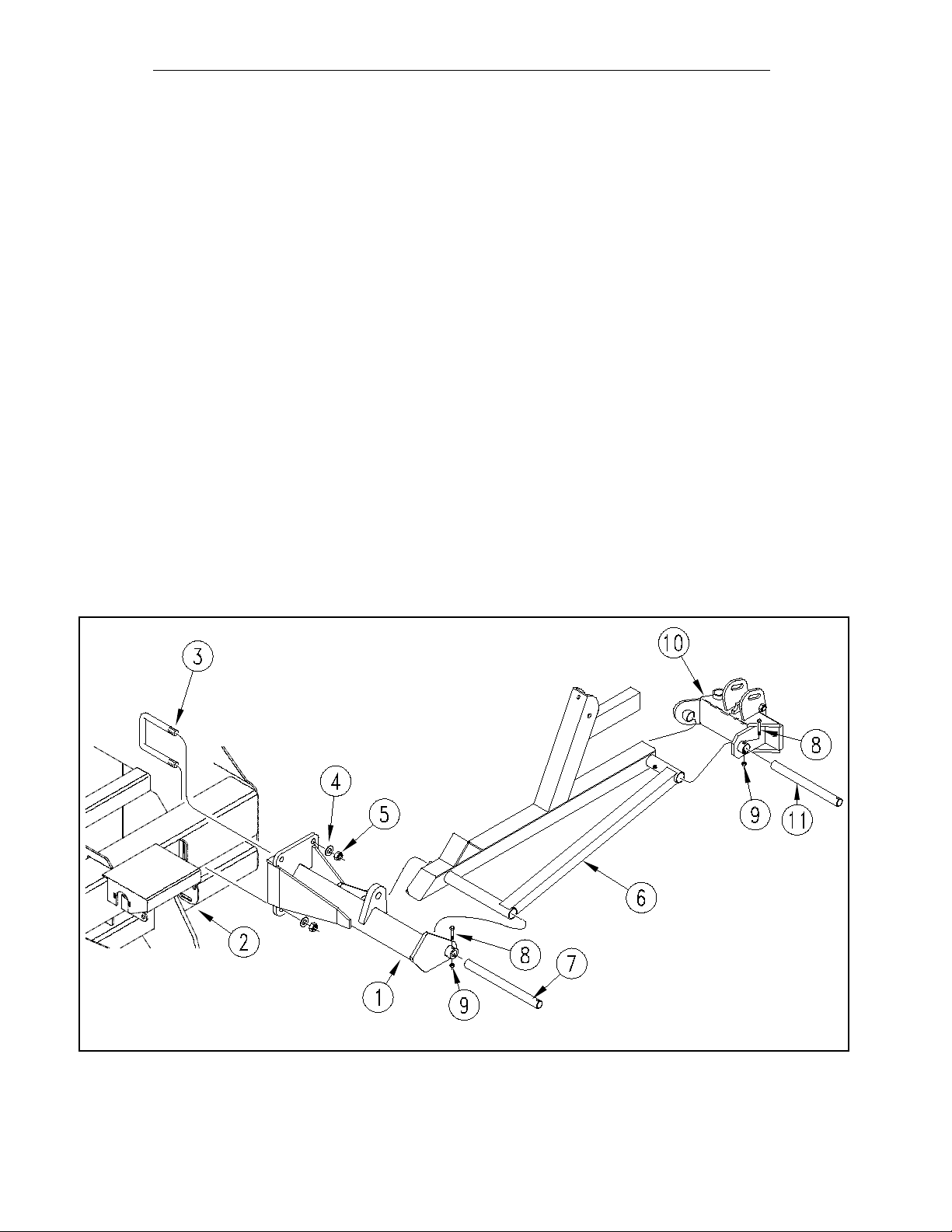
3. Referring to Fig. 1, install the left hand marker mount (# 1) on the left box (# 2). The mount is fastened to the drill
using two u-bolts (# 3), lock washers (# 4) and nuts (# 5). Install the first section of the marker (# 6) on the mount (# 1)
by pushing the pivot shaft (# 7) through the pivot holes on the mount and the first section. Use the bolt (# 8) and lock nut
(# 9) to retain the shaft in the mount.
Mount the left hand breakaway hinge (# 10) onto the first section (# 6) by pushing the pivot shaft (# 11) through the pivot
holes in each part. Use the bolt (# 8) and lock nut (# 9) to retain the shaft.
113-395M
11200
Fig. 1
Page 6
4/9/04
1-4
INSTALLATION INSTRUCTIONS: 1993 2SNT 24’ & 2SNT 30’ MARKERS (CON’T.)
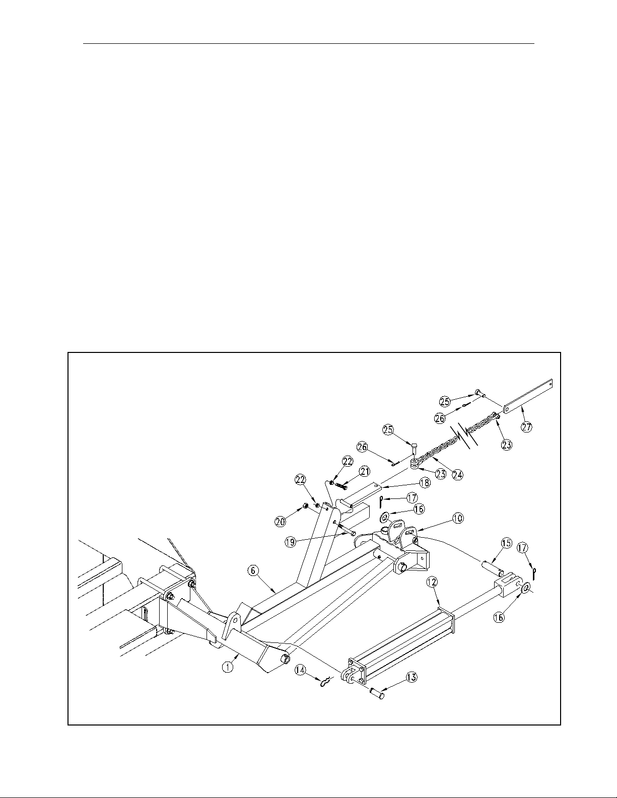
4. Referring to Fig. 2, pin the base end of the hydraulic cylinder (# 12) to the marker mount (# 1) using the pin and retainer (#13 & 14). Remove the plastic shipping plugs from the cylinder ports, and pull the rod end of the cylinder out to
its maximum length. Pin the rod end of the cylinder by working the cylinder pin (# 15) through one slotted ear on the
breakaway hinge (# 10), through the cylinder's rod end clevis, and out the other ear on the hinge. The rod end pin is
retained by placing the flat washers (# 16) on the outside of the slotted ears, and cotter pins (# 17) through the holes in
the pin.
Again referring to Fig. 2, install the chain bar weldment (# 18) on the first section (# 6). The chain bar should pivot freely
around the bolt (#19) which is fastened with lock nut (# 20). Directly below the pivot bolt for the chain bar weldment (#
18) is a single hole in which the full threaded adjustment bolt (# 21) is installed. To install, first thread one lock nut (# 22)
up the entire threaded length of the bolt. Next, push the bolt with nut through the hole in the mast of the first section (#
6), and complete the assembly by threading a second lock nut (# 22) up the entire remaining length of the full threaded
bolt.
Information on the adjustment of this bolt, which is designed to take the slack out of the chain when the marker is in the
folded position, can be found in the "Adjustments" section on
adjustment bolt extend as little as possible which will prevent the parts from being damaged the first time the marker is
folded.
Thread a utility clevis (# 23) through one end of the chain (# 24). Pin this clevis to the chain bar weldment (# 18) using
the pin and cotter (# 25 & 26) that came with the utility clevis. Do not fully bend the cotter pin at this time, the chain will
be adjusted later before the marker is folded for the first time. Chain length adjustments are done at the end of the chain
towards the center of the drill. Thread a second utility clevis (# 23) through the last link at the opposite end of the chain
(# 24). Pin this clevis to the chamfered end of the chain bar (# 27) using the pin and cotter (# 25 & 26) that came with
the utility clevis.
page 12. For now, it is important that the head of the
11164
Fig. 2
113-395M
Page 7
1-5
4/9/04
INSTALLATION INSTRUCTIONS: 1993 2SNT 24’ & 2SNT 30’ MARKERS (CON’T.)
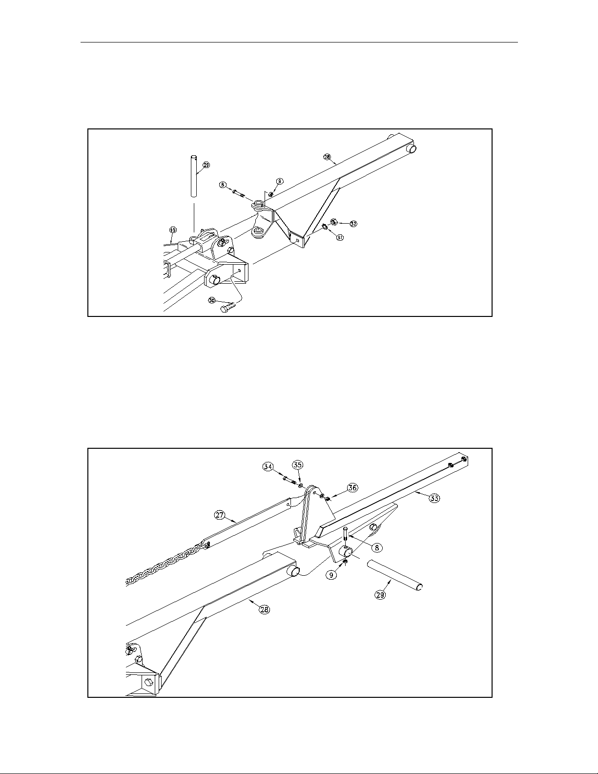
5. Referring to Fig. 3, attach the 2nd section maker weldment(# 28) to the breakaway hinge (# 10) by passing the pivot
pin (# 29)through the pivot hole in the hinge and weldment. Retain the pivot pin (# 29) with the bolt and lock nut (# 8 &
9). Complete this joint by passing the special GRADE 2 breakaway bolt(# 30)through the holes in the hinge and 2nd
section. Install the lock washer (# 31) and nut (# 32) on this bolt.
NOTE: The breakaway bolt (# 30) is a 7/16"-14 x 2" long - grade 2 (G.P. # 802-353C) It is identified as a grade 2 by
having no marks on the head. If it breaks, it must be replaced by an equivalent grade 2 bolt to prevent marker damage.
11101
Fig. 3
6. Referring to Fig. 4, attach the 3rd section (# 33) to the 2nd section (# 28) by using the pivot pin (# 29). Retain the
pivot pin with the bolt (# 8) and lock nut (# 9).
Note: The next few steps are made easier if the marker's outer sections are lifted off the ground by a support approximately 12" to 18" tall placed under the outer end of the 3rd section (# 33).
Pull the loose end of the chain and chain bar (# 27) out and fasten the chain bar to the ears on the 3rd section (# 33) by
using the bolt (# 34) flat washers (# 35) and lock nut (# 36). Do not over tighten this pivot and cause the ears to bend
in. The chain bar must pivot freely around the bolt.
113-395M
11102
Fig. 4
Page 8
4/9/04
INSTALLATION INSTRUCTIONS: 1993 2SNT 24’ & 2SNT 30’ MARKERS (CON’T.)
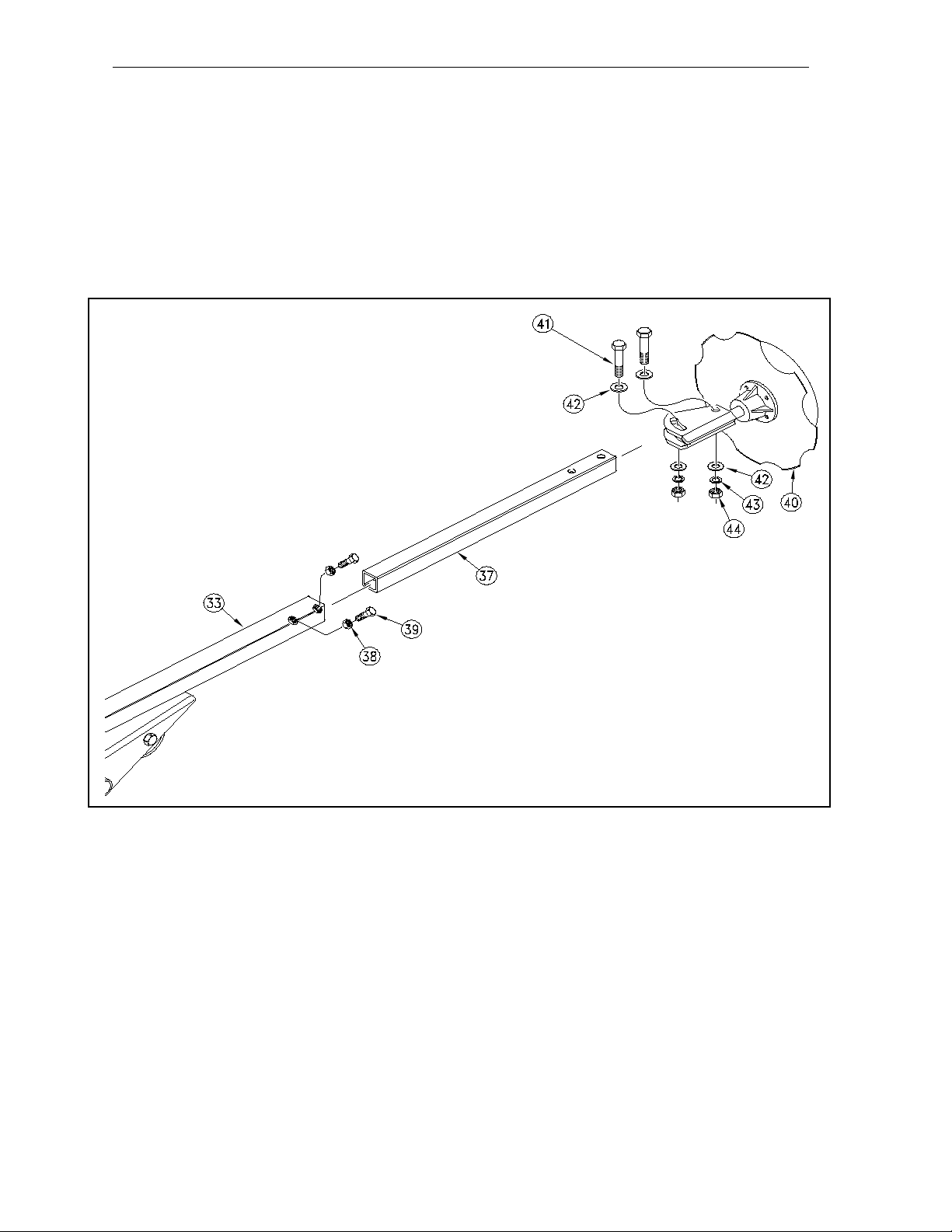
7. Referring to Fig. 5, slide the fourth section tube (# 37) inside the 3rd section (# 33). The holes in the 4th section must
be to the outside of the drill and need to be on the top and bottom side as shown. Thread the jam nuts (# 38) on the
square headed set screws (# 39). Thread the set screws into the nuts welded to the outer end of the 3rd section (# 33).
Tighten the set screws and jam nuts.
8. Again referring to Fig. 5, slide the blade and spindle assembly (# 40) over the 4th section tube (# 37).Pass the bolt
(# 41) through a flat washer (# 42), through the hole in the spindle weldment, and through the holes in the 4th section
tubing. Complete the joint by fastening a flat washer (# 42), a lock washer (# 43) and a nut (# 44) onto the bolt. In a
similar manner, install the second bolt through the adjustment slot, next the first bolt. Tighten these two nuts.
1-6
Fig. 5
11103
113-395M
Page 9
1-7
4/9/04
INSTALLATION INSTRUCTIONS: 1993 2SNT 24’ & 2SNT 30’ MARKERS (CON’T.)
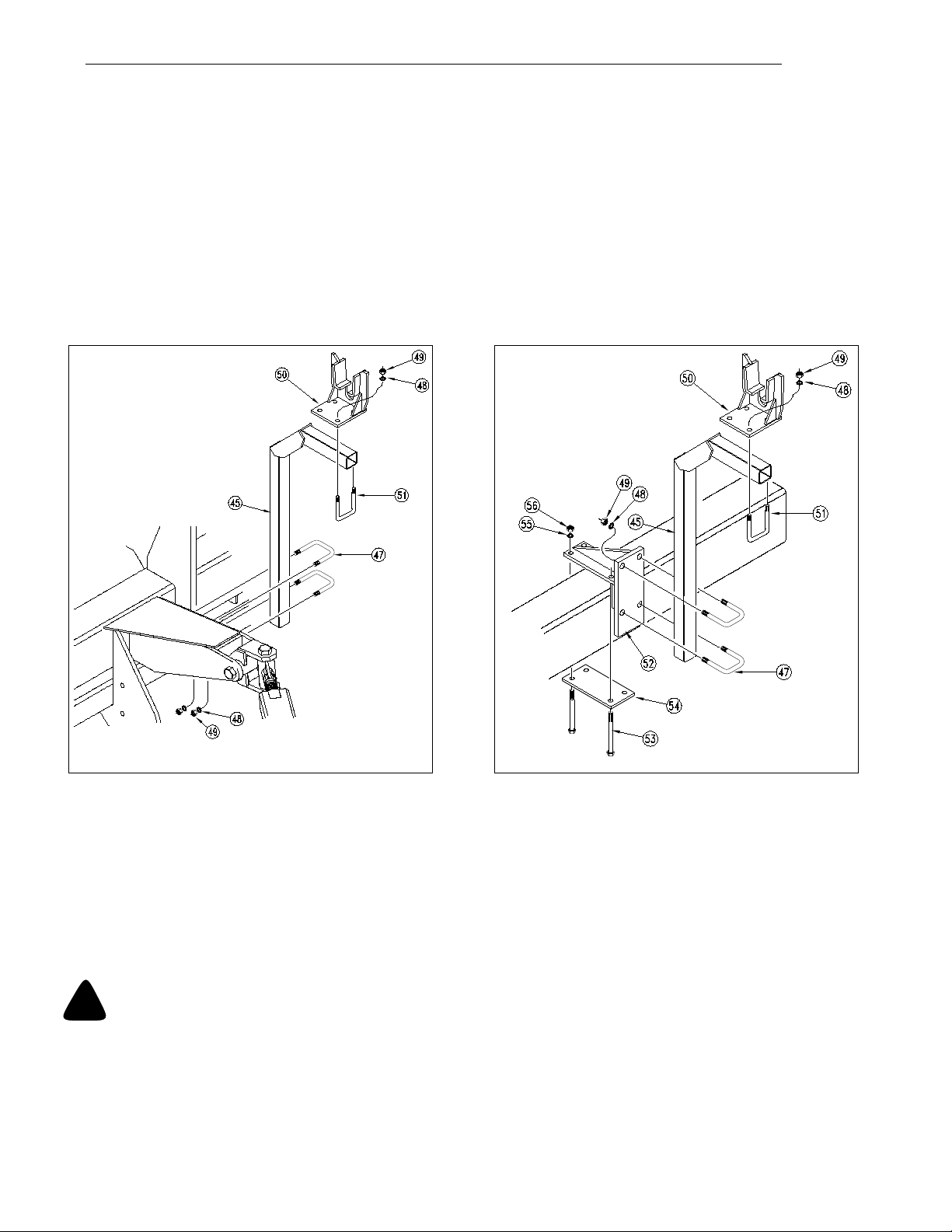
9. The transport carrier arm (# 45) will bolt directly to the pull bar lugs on the 30’ box frame Fig. 6. Hold the carrier in
place by passing the two u-bolts (# 47) over the carrier tube, and through the holes in pull bar ears.Tentatively, tighten
the u-bolts with the lock washers (# 48) and nuts (#49) so that the top of the carrier is approximately29 3/8" above the
top surface of the box's 6" x 8" frame tube. On the 24’ drill
tween the cylinder lug and the pull bar mount by means of the mounting bracket (#52). It is held in place with the two
1/2" x 6" x 9 1/4" u-bolts (#53), flat washer, lock washer, & nut (#54, #55, #56). Fasten the carrier to the mount by passing
the two u-bolts (# 47) over the carrier tube, and through the holes in the pull bar ears.Tentatively, tighten the u-bolts with
the lock washers (# 48) and nuts (#49) so that the top of the carrier is approximately 29 3/8" above the top surface of
the box's 6" x 8" frame tube.
Mount the transport saddle (# 50) on the top of the carrier arm (# 45) using the u-bolts (# 51), lock washers (# 48) and
nuts (# 49). On 24' drills
outside of the drill as shown.
Fig. 7 it is important that the saddle (# 50) be positioned so that the offset in the saddle is to the
Fig. 7, the transport carrier is mounted to the box frame be-
11201
Transport Carrier Mounting 30’ Drill
Fig. 6
NOTE:
Dual Marker Installations: To complete the installation, repeat steps 3 through steps 9 on the opposite marker.
All Installations: After all parts are in place, go back over the entire installation and tighten every bolt and u-bolt.
Refer to the torque chart in the front of your drill's owners manual. U-bolts can be torqued to grade 5 bolt values.
When finished, read and follow the MARKER HYDRAULIC SYSTEM INSTALLATION section of this manual.
!
CAUTION! BEFORE FOLDING THE MARKER(S) FOR THE FIRST TIME, READ THE
Transport Carrier Mounting 24’ Drill
Fig. 7
11701
SECTION ON ADJUSTMENTS IN THIS MANUAL.
113-395M
Page 10
4/9/04
1-8
MARKER HYDRAULIC SYSTEM INSTALLATION
INSTALLING: 24 or 30' SINGLE MARKER HYDRAULICS
GENERAL NOTE: JIC fittings do not require high torque. JIC and O-ring fittings do not require sealant. To avoid cracking
fittings or castings from overtightening, DO NOT use plastic sealant tape.
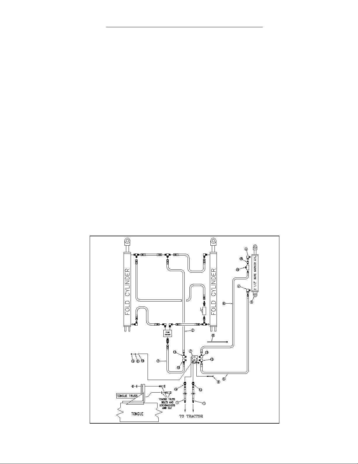
REFER TO THE PICTORIAL HYDRAULIC SCHEMATIC Fig. 8 WHEN INSTALLING SINGLE MARKER HYDRAULICS.
1. Attach the 90˚ swivel elbow (#4) to the base and rod end of the marker cylinder (#3). Thread the close nipple (#15)
in the swivel of the elbow (#4), and thread the needle valve (#16) on the close nipple.
2. Uncoil and attach hose (#6) to the needle valve (#16) on the rod end of the marker cylinder (#3). Uncoil and attach
hose (#5) to the swivel elbow (#4) attached to the base end of the marker cylinder (#3). Route these two hoses through
the frame member cut-outs and hose clamps. Parallel to the hoses feeding the outer gage wheel cylinder as shown in
Fig. 9 on page 1-9. Place the hoses in the clamps later, after the free ends are plumbed.
3. Remove the three bolts (#18) from the top of the tongue truss and install the valve mount plate (#17) under them.
Referring back to schematic Fig. 8, Bolt the selector valve (#7) to the valve mount. The valve is held in place with bolts
(#9), flat washers (#10), lock washers (#11) and nuts (#12).
4. Install the four elbow fittings (#13) in the side ports of the selector valve (#7). Install the two straight fittings (#14) in
the two top ports of the selector valve (#7).
5. Locate the two long hoses (#1) coming from the tractor, going to the fold cylinders. Break the first hose at the “T”
between the rod end of the fold cylinders, the second at the flow divider. Take these same two hoses and install them
on the top two selector valve fittings (#14).
6. The two hoses just removed from the fold cylinders are replaced by two shorter hoses (#2). Run one from the “T”
between the rod end of the fold cylinders to the elbow (#13) on the side of the selector valve. Run the other from the fold
cylinder's base end flow divider to the adjacent elbow (#13).
7. The last hoses to connect should be the two coming from the marker cylinder. Connect these to the two remaining
elbows (#13) on the selector valve (#7) as shown.
Single Marker Hydraulics
Fig. 8
11165
113-395M
Page 11
1-9
4/9/04
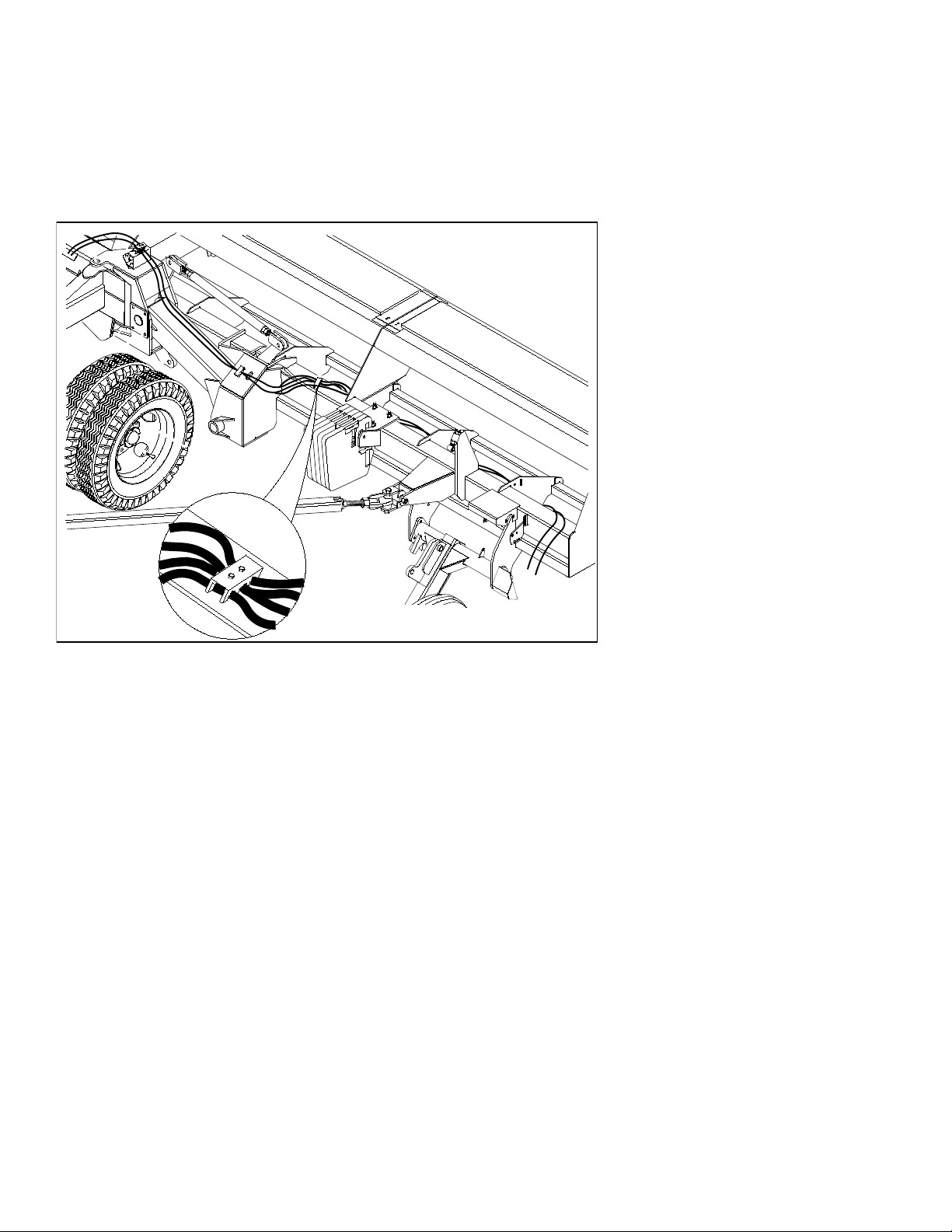
HOSE CLAMPING AND ROUTING
8. Refer to the hose routing illustration Fig. 9, to fine tune the hose placement. Make a generous loop in both hoses
near the box's flex hinge. This loop should be large enough to allow the outer box wing to flex without the hoses pulling
tight. Maintain the loops by clamping the hoses in the center hole of the existing hose clamps, using the split rubber
sleeves as bushings between the clamps and the marker hose. Use the cable ties supplied with the kit to hold the hoses
away from any pinch point along their path.
Hydraulic Hose Routing
Fig. 9
11161
113-395M
Page 12

4/9/04
1-10
MARKER HYDRAULIC SYSTEM INSTALLATION (CON’T.)
INSTALLING: 24 or 30' DUAL MARKER HYDRAULICS
GENERAL NOTE: JIC fittings do not require high torque. JIC and O-ring fittings do not require sealant. To avoid cracking fittings or castings from overtightening, DO NOT use plastic sealant tape.
REFER TO THE PICTORIAL HYDRAULIC SCHEMATIC Fig. 10 WHEN INSTALLING: 24 or 30' DUAL MARKER HYDRAULICS
1. Attach the 90˚ swivel elbows (#4) to the base and rod end of both marker cylinders (#3).
2. Uncoil and attach hoses (#5 & 6) to the swivel elbows (#4) attached to the marker cylinder (#3). Note that the longer
of the two hoses goes to the rod end of the cylinder. Route these two hoses through the frame member cut-outs and
hose clamp. Parallel to the hoses feeding the outer gage wheel cylinder as shown in
hoses in the clamps later, after the free ends of the hoses are plumbed.
3. Remove the three bolts (#15) from the top of the tongue truss and install the valve mount plate (#14) under them.Referring back to schematic Fig. 10, Bolt the selector/sequence valve (# 7) to the valve mount. The valve is held in place
with bolts (#9), flat washers (#10), lock washers (#11) and nuts (#12).
4. As noted in the schematic, Fig. 10, switch the elbow and straight fittings on ports A and G of the sequence/selector
valve (#7). Do the same for ports B and J. Next, install the two elbow fittings (#13) on ports E and F.
Fig. 11 on page 1-11. Place the
5. Locate the two long hoses (#1) coming from the tractor, going to the fold cylinders. Break the first hose at the “T”
between the rod end of the fold cylinders, the second at the flow divider. Take these same two hoses and install them
on the selector/sequence valve (#7) ports A and B.
6. The two hoses just removed from the fold cylinders are replaced by two shorter hoses (#2). Run one from the “T”
between the rod end of the fold cylinders to port G on the top of the selector/sequence valve (#7). Run the other from
the fold cylinder's base end flow divider to the adjacent port J.
7. The last hoses to connect should be the four coming from the marker cylinders. Connect the base end hoses (#5) to
ports E and F on the selector valve (#7), and the rod hoses (#6) to ports C and D as shown.
Dual Marker Hydraulic Schematic
Fig. 10
11166
113-395M
Page 13

1-11
4/9/04
HOSE CLAMPING AND ROUTING
8. Refer to the hose routing illustration Fig. 11 to fine tune the hose placement. Make a generous loop in both hoses
near the box's flex hinge. This loop should be large enough to allow the outer box wing to flex without the hoses pulling
tight. Maintain the loops by clamping the hoses in the existing hose clamps, using the split rubber sleeves as bushings
between the clamps and the marker hose. Use the cable ties supplied with the kit to hold the hoses away from any pinch
point along their path.
Hydraulic Hose Routing
Fig. 11
11161
113-395M
Page 14

4/9/04
1-12
MARKER ADJUSTMENTS
STORAGE SADDLE ADJUSTMENT
When folding the marker for the first time, it may be necessary to move the marker storage saddle, Transport Carrier
Mounting 24’ Drill (#50) into alignment with the 2nd section of the marker arm. Slowly fold the marker(s) and stop when
the marker is just above the storage saddle. Adjust the bracket(s) in or out as needed.
TRANSPORT CARRIER ADJUSTMENT
After centering the storage saddle(s) and folding the marker(s), visually check to see if the height of the transport carrier
is correct. Transport Carrier Mounting 24’ Drill (#45). The 2nd section of the marker should appear parallel with the top
of the drill box. If not, loosen the transport carrier u-bolts (#47) and adjust the carrier up or down.
MARKER CHAIN ADJUSTMENT
There are two basic adjustments needed on the marker chain, especially in new installations. They are interrelated, and
should be done in the following order:
1. Lifting Slack. Start with the marker in the unfolded position. Back the full threaded adjustment bolt Fig. 2 on page 14 (#21) down until the head extends as little as possible. Slowly fold the marker, observing the motion of the disk. If the
marker disk slides across the ground more than about one foot before the chain and linkage lifts it up, the chain is too
slack. Tighten the chain by moving the clevis one or two links at the inboard end of the chain. Recheck by repeating step
1.
If the chain does not have enough slack when the marker is in the unfolded field position, the chain will prevent the end
of the marker from dropping down to follow a depression in the field. Correct this condition by moving the utility clevis
one or two links, giving the chain more slack.
2. Folding Slack. After the adjustments in step one have been completed, fold the marker(s). The full threaded adjustment bolt Fig. 2 on page 1-4 (#21) is provided to take the slack out of the chain while the marker is in the folded position.
Extend this bolt until the slack is out of the chain. Lock the bolt in this position by tightening the nuts on either side of the
upright channel on section 1.
DISK ADJUSTMENTS
The aggressiveness and the mark left by the disk may be changed by two methods:
1. Disk Angle. To change the angle of cut, loosen the two bolts (#41) Fig. 5 on page 1-6, rotate the disk assembly and
retighten.
2. Direction Of Cut. The disk may be mounted to throw dirt either in or out which will give different marks in different soil
conditions. To change the direction of cut:
a. Reverse the blade and depth band by remounting the four lug bolts on the disk hub.
b. Reverse the angle of the assembly by removing the adjustment bolts (#41) Fig. 5 on page 1-6 and turning the
spindle assembly one half turn. Reinstall and tighten all bolts.
113-395M
Page 15

1-13
4/9/04
MAINTENANCE AND LUBRICATION
BREAKAWAY PROTECTION
The 3 outer sections of the marker are attached to the first section by a hinge pin and a breakaway bolt. The bolt is
designed to pull apart if the outer sections contact an obstruction while using the drill.
NOTE: The breakaway bolt is a 7/16"-14 x 2" long - grade 2 (G.P. # 802-353C). It is identified as a grade 2 by having
no marks on the head. If it breaks, it must be replaced by an equivalent grade 2 bolt to prevent marker damage. See
Fig. 12.
11147
Breakaway Protection
Fig. 12
LUBRICATION
HINGES
Each hinge on the marker requires greasing every 20-25 hours of operation. A grease fitting is located on the hinge
tube at the base end of each section.
DISK BEARINGS
The tapered roller bearings in the disk hub are lubricated at the factory. Under normal conditions, the bearings need to
be repacked every 2 to 3 years. If the grease seal or grease cap becomes damaged or is missing, the hub should be
disassembled, cleaned and bearings repacked. A new seal or grease cap should be installed.
MARKER TRANSPORTING
Always transport the marker with it folded in the flat fold position. Make sure the second marker section(s) rests securely
on the transport carrier(s).
113-395M
Page 16

4/9/04
1-14
BLEEDING OF THE HYDRAULICS
1. Be sure tractor hydraulic reservoir if full.
2. With the marker(s) in field position, crack the hydraulic hose fitting(s) located at the base end of the cylinder(s). With
your tractor at an idle speed, activate your tractor hydraulic valve until hydraulic oil seeps out around the hose ends.
Tighten the hose end fittings and repeat this process with the hose end fitting(s) located at the rod end of the cylinder(s).
If dual markers are used with a selector/sequence valve, follow the procedure above for one marker cylinder. Then
crack the fittings on the back side of the selector/sequence valve, activate the tractor hydraulics valve until hydraulic oil
seeps out around the hose ends. Tighten the hose end fittings and repeat the complete process for the opposite marker
cylinder.
3. Fold and unfold the marker(s) slowly in order to work all the air out of your marker hydraulics. Use caution when folding and unfolding the marker for the first time, and check for pinching and kinking of hoses.
CAUTION! NEVER ALLOW ANYONE NEAR THE DRILL WHEN CYCLING THE
!
4. When the marker cylinder is equipped with a needle valve (#16) of Fig. 8 on page 1-8, screw the needle valve in to
adjust the marker speed to a low setting. Fold the marker up and down a few times and recheck for pinching and kinking
of hoses. With the tractor engine at an operating rpm, adjust the needle valve to limit the marker to a safe operating
speed. When markers are equipped with a selector/sequence valve, the valve has an internal orifice that regulates the
marker speed.
MARKERS!
CAUTION! EXCESSIVE FOLDING SPEEDS CAN CAUSE MARKER DAMAGE!
CAUTION! ESCAPING FLUID UNDER PRESSURE CAN HAVE SUFFICIENT
!
!
FORCE TO PENETRATE THE SKIN. CHECK ALL HYDRAULIC LINES AND HOSES BEFORE APPLYING PRESSURE. FLUID ESCAPING FROM A VERY SMALL HOLE CAN BE
ALMOST INVISIBLE
. USE PAPER OR CARDBOARD, NOT BODY PARTS, TO CHECK FOR
SUSPECTED LEAKS. IF INJURED, SEEK MEDICAL ASSISTANCE FROM A DOCTOR THAT
IS FAMILIAR WITH THIS TYPE OF INJURY. FOREIGN FLUIDS IN THE TISSUE MUST BE
SURGICALLY REMOVED WITHIN A FEW HOURS OR GANGRENE WILL RESULT.
MARKER HYDRAULICS, GENERAL NOTES...
THE MARKERS CYCLE IN THE FOLLOWING SEQUENCE:
(1) Right Up, Left Up
(2) Right Down, Left Up
(3) Right Up, Left Up
(4) Right Up, Left Down
(5) Sequence Repeats
To fold the wing boxes for transporting, position the handle on the selector/sequence valve towards the port marked "G".
Hydraulic oil is now diverted to the fold cylinders.
NOTE: Raising and lowering speed of the dual markers is regulated by an internal orifice in the sequence valve which
is sized for proper operation of the valve spool. DO NOT try to adjust or alter this orifice size. This will cause failure of
the sequence valve.
NOTE: JIC fittings do not require high torque. JIC and O-Ring fittings do not require sealant. Always use liquid
pipe sealant when adding or replacing pipe thread fittings. To avoid possible danger of cracking hydraulic fittings from over tightening,
DO NOT use plastic sealant tape.
113-395M
Page 17

1-15
TROUBLE SHOOTING
PROBLEM SOLUTION
Hydraulic marker functioning improperly a. Check all hose fittings and connections for air and oil leaks.
b. The chain on the folding marker should be slack when the marker
is both fully extended and fully raised.
c. Check tractor hydraulic oil level.
d. Check all bolts and fasteners.
e. If needle valve is plugged; open valve, cycle markers, and reset
the needle valve.
f. Double selector valve positioned for fold cylinders. Shift valve to
marker sequence position.
Blade does not mark a. The marker folding linkage and chain must have enough slack to
allow the marker disk to drop down into depressions in the field.
Maximum down float should be limited by the slots at the rod end
of the marker cylinder, and not by the chain Read the adjust-
ments section of this manual when adding slack to the chain.
b. The blade may be reversed to pull dirt in or throw dirt out depend-
ing on soil conditions. See disk adjustments in this manual.
c. An optional smooth blade is available through your Great Plains
dealer. The notched blade comes with your marker as standard
equipment.
4/9/04
113-395M
Page 18

4/9/04
1-16
WARRANTY
Great Plains Manufacturing, Incorporated warrants to the original
purchaser that this Grain Drill will be free from defects in material and
workmanship for a period of one year from the date of original pur
chase when used as intended and under normal service and conditions for personal use; 90 days for commercial or rental purposes.
This Warranty is limited to the replacement of any defective part by
Great Plains Manufacturing, Incorporated and the installation by the
dealer of any such replacement part. Great Plains reserves the right
to inspect any equipment or part which are claimed to have been defective in material or workmanship.
This Warranty does not apply to any part or product which in
Great Plains’ judgement shall have been misused or damaged by accident or lack of normal maintenance or care, or which has been repaired or altered in a way which adversely affects its performance or
reliability, or which has been used for a purpose for which the product
is not designed. This Warranty shall not apply if the product is towed
at a speed in excess of 20 miles per hour.
Claims under this Warranty must be made to the dealer which
originally sold the product and all warranty adjustments must by
made through such dealer. Great Plains reserves the right to make
changes in materials or design of the product at any time without notice.
This Warranty shall not be interpreted to render Great Plains liable for damages of any kind, direct, consequential, or contingent, to
property. Furthermore, Great Plains shall not be liable for damages
resulting from any cause beyond its reasonable control. This Warranty does not extend to loss of crops, losses caused by harvest delays or any expense or loss for labor, supplies, rental machinery or
for any other reason.
No other warranty of any kind whatsoever, express or implied, is made with respect to this sale; and all implied warranties of merchantability and fitness for a particular purpose
which exceed the obligations set forth in this written warranty
are herby disclaimed and excluded from this sale.
This Warranty is not valid unless registered with Great Plains
Manufacturing, Incorporated within 10 days from the date of original
purchase.
113-395M
Page 19

1-17
4/9/04
113-395M
Page 20

4/9/04
1-18
24’ & 30’
2-SECTION NO-TILL
FLAT FOLD MARKER
PARTS DRAWINGS TABLE OF CONTENTS
24’ & 30’ Marker-------------------------------------------1-19
Disk & Bearing Assembly ------------------------------- 1-21
Single Marker Schematic-------------------------------- 1-23
Dual Marker Schematic---------------------------------- 1-25
2 1/2" x 20" Cylinder {810-118C}---------------------- 1-27
Double Selector Valve {810-023C} -------------------1-29
Selector / Sequence Valve {810-085C}-------------- 1-31
PARTS BOOK
113-395M
Page 21

1-19
4/9/04
MARKER ASSEMBLY
11154
113-395M
Page 22

4/9/04
Ref. Part No. Description
1-20
MARKER ASSEMBLY (CON’T.)
1. 113-381H 2SNT Left Hand Marker Mount {Shown}
113-382H 2SNT Right Hand Marker Mount
2. 806-037C U-Bolt 3/4"-10 x 8 1/32" x 9 1/2" Long
3. 804-023C Washer, Lock 3/4"
4. 803-027C Nut, Hex 3/4"-10
5. 113-312D First Pivot Shaft
6. 802-152C Bolt, Hex Head 1/4"-20 x 2" Long Gr 5
7. 803-007C Nut, Lock 1/4"-20
8. 890-005C Bushing, Cylinder 1 1/4" x 1" x 1" Long
9. 113-180H Left Hand First Section {Shown}
113-188H Right Hand First Section
10. 800-001C Zerk Straight 1/4"-28
11. 810-118C Hydraulic Cylinder 2 1/2" x 20" x 1 1/8" Rod
12. 804-029C Washer, Flat 1" SAE
13. 805-058C Pin, Cotter 3/16" x 2" Long
14. 113-248D Marker Cylinder Pin Body
15. 802-353C Bolt, Hex 7/16"-14 x 2" Long Gr 2
16. 804-014C Washer, Lock 7/16"
17. 803-015C Nut, Hex 7/16"-14
18. 803-019C Nut, Lock 1/2"-13
19. 113-350H No-Till Breakaway Joint Left Hand {Shown}
113-351H No-Till Breakaway Joint Right Hand
20. 802-168C Bolt, Hex Head 3/8"-16 x 3 1/4" Long
21. 803-013C Nut, Lock 3/8"-16
22. 802-261C Bolt, Hex 3/8"-16 x 2 1/2" Long Full Thread
23. 113-313D Second Pivot Shaft
24. 113-200H Chain Bar Weldment
25. 890-018C Utility Clevis 5/16"
26. 113-311D Hinge Pin 10 1/8" Long
27. 802-201C Bolt, Hex Head 1/2"-13 x 4 3/4" Long
28. 113-325D Stop Bushing
29. 113-324D Cylinder Stop
30. 113-328D 24' Marker Chain
113-319D 30' Marker Chain
31. 113-342H No-Till Marker 24' Second Section
113-341H No-Till Marker 30' Second Section
32. 113-323D Chain Bar
33. 802-022C Bolt, Hex Head 3/8"-16 x 1 1/2" Long Gr 5
34. 804-011C Washer, Flat 3/8" USS
35. 802-260C Bolt, Hex 1/2"-13 x 7" Long
36. 113-398D Rubber Bumper Tube 3" OD x 5" Long
37. 113-344H No-Till Marker 24' 3rd Section
113-343H No-Till Marker 30' 3rd Section
38. 803-036C Nut, Hex Jam 1/2"-13
39. 801-013C Screw Set Square Head 1/2"-13 x 1 1/2" Gr 5
40. 113-379D No-Till 24' 4th Sect Tube
113-378D No-Till 30' 4th Sect Tube
41. 804-017C Washer, Flat 1/2" USS
42. 802-041C Bolt, Hex Head 1/2"-13 x 3 1/2" Long Gr 5
43. 113-360S No-Till Marker Disk & 4-Bolt Hub Assembly. Includes Spindle, Hub, Bearings, Seal, Cap, Bolts,
Nuts, Notched Disk And Depth Band.
44. 804-015C Washer, Lock Spring 1/2"
45. 803-020C Nut, Hex 1/2"-13
46. 806-023C U-Bolt 1/2"-13 x 2 x 3 1/4" Long
47. 113-197H Marker Carrier
48. 806-005C U-Bolt 1/2"-13 x 2 x 3" Long
49. 113-365H No-Till Saddle Rest Weldment
50. 113-316H Transport Arm Mount
51. 806-097C U-Bolt 1/2"-13 X 6 1/32" x 9 1/4" Long
113-395M
Page 23

1-21
4/9/04
MARKER DISK & BEARINGS
11156
113-395M
Page 24

4/9/04
MARKER DISK & BEARINGS (CON’T.)
Ref. Part No. Description
1. 113-360S No-Till Marker Disk & 4-Bolt Hub Assembly
2. 113-345H No-Till Marker Disk Spindle
3. 816-014C Seal
4. 822-030C Bearing Cone 1" {L44643}
5. 822-080C Bearing Cup {L44610}
6. 802-125C Bolt, Lug Square Neck 1/2"-13 x 1 3/8" Long G5
7. 815-001C Hub Assembly. Includes Items 3, 4, 5, 6, 7, 8 & 12.
8. 803-159C Nut, Lug 1/2"-20 x 60˚ Plated
9. 804-025C Washer, Flat 3/4" SAE Plated
10. 803-053C Nut, Hex Slotted 3/4"-16
11. 805-045C Pin, Cotter 5/32" x 1 1/4" Long
12. 890-068C Grease Cap
13. 113-346H Depth Band 12" 4-Bolt
14. 820-094C 16" 4-Bolt Notched Marker Disk
1-22
113-395M
Page 25

1-23
4/9/04
SINGLE HYDRAULIC SCHEMATIC
11165
113-395M
Page 26

4/9/04
SINGLE HYDRAULIC SCHEMATIC (CON’T.)
Ref. Part No. Description
1. Existing Hose From Tractor
2. 811-333C Hydraulic Hose 1/4" x 32" R1
3. 810-118C Hydraulic Cylinder 2 1/2" x 20" Stroke
4. 811-281C Hydraulic Fitting 3/8" FNPT x 9/16" MORB
5. 811-035C Hydraulic Hose 1/4" x 252" {24’ Drill}
811-014C Hydraulic Hose 1/4" x 288" {30’ Drill}
6. 811-293C Hydraulic Hose 1/4" x 272" {24’ Drill}
811-342C Hydraulic Hose 1/4" x 308" {30’ Drill}
7. 810-023C Double Selector Valve
8. 800-082C Cable Tie
9. 802-024C Bolt, Hex Head 3/8"-16 x 3" Long
10. 804-011C Washer, Flat 3/8" USS
11. 804-013C Washer, Lock 3/8"
12. 803-014C Nut, Hex 3/8"-16
13. 811-134C Hydraulic Fitting 9/16" JIC x 1/2" MNPT
14. 811-066C Hydraulic Fitting 9/16" MJIC x 1/2" MNPT
15. 811-044C Hydraulic Fitting 3/8" NPT Close Nipple
16. 810-058C Needle Valve 3/8”
1-24
113-395M
Page 27

1-25
4/9/04
DUAL HYDRAULIC SCHEMATIC
11166
113-395M
Page 28

4/9/04
DUAL HYDRAULIC SCHEMATIC (CON’T.)
Ref. Part No. Description
1. Existing Hose From Tractor
2. 811-333C Hydraulic Hose 1/4" x 32" R1
3. 810-118C Hydraulic Cylinder 2 1/2" x 20" Stroke
4. 811-281C Hydraulic Fitting 3/8" FNPT x 9/16" MORB
5. 811-035C Hydraulic Hose 1/4" x 252" {24’ Drill}
811-014C Hydraulic Hose 1/4" x 288" {30’ Drill}
6. 811-293C Hydraulic Hose 1/4" x 272" {24’ Drill}
811-342C Hydraulic Hose 1/4" x 308" {30’ Drill}
7. 810-085C Selector / Sequence Valve
8. 800-082C Cable Tie
9. 802-024C Bolt, Hex Head 3/8"-16 x 3" Long
10. 804-011C Washer, Flat 3/8" USS
11. 804-013C Washer, Lock 3/8"
12. 803-014C Nut, Hex 3/8"-16
13. 811-139C Hydraulic Fitting 6 JICM x 6 JICF Swivel Elbow
1-26
113-395M
Page 29

1-27
4/9/04
2 1/2” X 20” CYLINDER ASSEMBLY {810-118C}
11188
113-395M
Page 30

4/9/04
2 1/2” X 20” CYLINDER ASSEMBLY {810-118C} (CON’T.)
CROSS MIDWAY
Ref. Part No. Part No. Description
1. 1D0005-2250 5M3128 Midway Tube
2. 1D0204-2475 2M3326 Rod
3. 1D1003-4 1M6006 Rod Clevis
4. 2A0235-6 2A0012 Nut, Clevis
5. 2A0079-616 2A0006 Screw, Cap
6. 2A0578-2475 7M3328 Tie Rod
7. 2A0235-6 2A0012 Nut, Tie Rod
8. 1D1155-13 3M3310 Head
9. * * O-Ring Rod
10. * * Back-Up Rod
11. * * Rod Wiper
12. * * O-Ring Piston
13. 1D1401-250 4M3102 Piston
14. 4C2024 6M3128 Base
15. 2A0246-12 2A0022 Nut, Piston
16. * * Back-Up Piston
17. 1D1582-16275 2A0208 Pin, Clevis {Base End}
18. 2A0308-1 2A0132 Pin, Clip
1-28
810-119C 810-119C Seal Kit
* Available In Seal Kit Only
113-395M
Page 31

1-29
4/9/04
DOUBLE SELECTOR VALVE {810-023C}
10038
113-395M
Page 32

4/9/04
DOUBLE SELECTOR VALVE {810-023C} (CON’T.)
Shoemaker
Ref. Part No. Description
1. 3062 Body
2. 1079 Retaining RIng Tru-Arc 5100-100
3. 1089-210 Teflon Backup RIng 0.210
4. 1088-210 O-Ring
5. 2007 Spool
6. 1083 Pin, Spring 0.312 Diameter x 4" Long
7. 1097 Knob
8. 1084 Pin, Spring 0.25 Diameter x 1 1/2” Long
1-30
113-395M
Page 33

1-31
4/9/04
SELECTOR / SEQUENCE VALVE {810-085C}
10240
113-395M
Page 34

4/9/04
SELECTOR / SEQUENCE VALVE {810-085C} (CON’T.)
Ref. Part No. Description
1. 4051 Body, Steel
2. 2044 Spool, Selector
3. 1088-210 O-Ring Buna N 70 Duro
4. 1089-210 Teflon Back Up
5. 1083 Pin, Spring 5/16" x 4" Long
6. 1082 Sleeve - Yellow Vinyl
7. 1079 Ring, Snap Truarc 5100-100
8. 1084 Pin, Spring 1/4" x 1 1/2" Long
9. 2031 Spool
10. 1132-10 Plug #10 SAE
11. 1087-250 Ball 1/4" Diameter Steel
12. 1087-437 Ball 7/16" Diameter Steel
13. 1042 Spring
14. 1066 Orifice & Guide
15. 1022 Port Adaptor
16. 1091-4-6 Fitting, Elbow 1/4" NPT To #6 JIC
17. 1092-6-6 Fitting, Straight SAE #6 To #6 JIC
18. 1092-6-6 Fitting, Straight SAE #8 To #8 JIC
19. 1093-6-6 Fitting, Elbow SAE #6 To #6 JIC
20. 1099 Compression Spring
21. 1098 Plug, O-Ring
1-32
113-395M
 Loading...