

Page 1
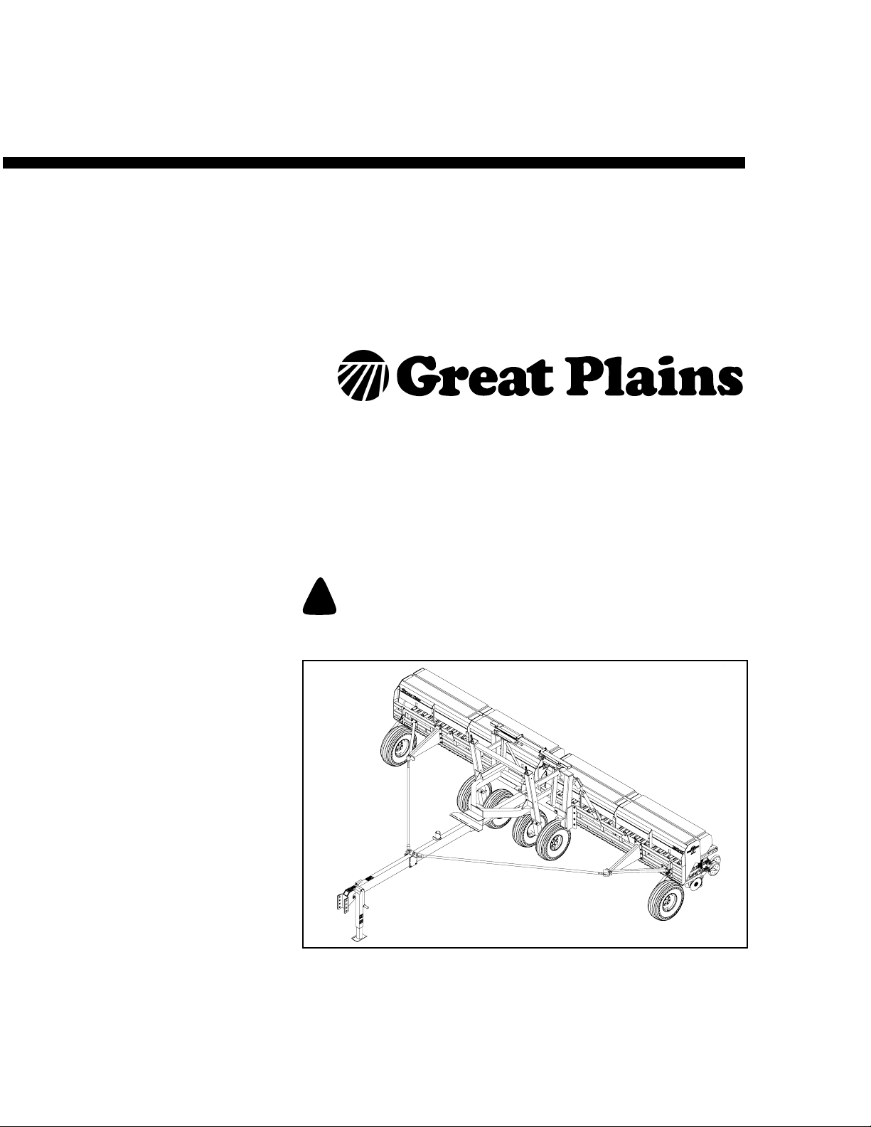
Operator’s Manual
2SNG24 & 2SNG30
24’ & 30’ 2-Section Native Grass
Manufacturing, Inc.
www.greatplainsmfg.com
Read the operator’s manual entirely. When you see this symbol, the subsequent
instructions and warnings are serious - follow without exception. Your life and
!
the lives of others depend on it!
Cover illustration may show optional equipment not supplied with standard unit.
© Copyright 2002 Printed 8/17/2006
202-499m
20160
Page 2

Table of Contents
Important Safety Information . . . . . . . . . . . . . . . . . 1
Safety Decals . . . . . . . . . . . . . . . . . . . . . . . . . . . 6
Introduction . . . . . . . . . . . . . . . . . . . . . . . . . . . . . . 11
Description of Unit . . . . . . . . . . . . . . . . . . . . . . . 11
Intended Usage. . . . . . . . . . . . . . . . . . . . . . 11
Models Covered . . . . . . . . . . . . . . . . . . . . . 11
Using This Manual. . . . . . . . . . . . . . . . . . . . . . . 12
Definitions . . . . . . . . . . . . . . . . . . . . . . . . . . 12
Owner Assistance . . . . . . . . . . . . . . . . . . . . . . . 13
Before You Start . . . . . . . . . . . . . . . . . . . . . 14
Assembly Instructions & Set Up. . . . . . . . . . . . . . 14
Assembling The Drill . . . . . . . . . . . . . . . . . . . . . 15
Tractor Draw Bar Hookup . . . . . . . . . . . . . . . . . 17
Tractor Requirements . . . . . . . . . . . . . . . . . . . . . . 17
Tractor Hydraulic Hookup . . . . . . . . . . . . . . . . . 18
Hydraulic Hose Hookup. . . . . . . . . . . . . . . . . . . 18
Bleeding Hydraulics. . . . . . . . . . . . . . . . . . . . . . 19
Bleeding the Lifting Hydraulic System. . . . . 19
Bleeding Folding Hydraulics . . . . . . . . . . . . 20
Leveling the Drill . . . . . . . . . . . . . . . . . . . . . . . . . . 21
Transport Wheel Adjustments . . . . . . . . . . . 22
Gauge Wheel Adjustments . . . . . . . . . . . . . 22
Box Alignment Adjustments. . . . . . . . . . . . . . . . 23
Pull Bar Adjustments. . . . . . . . . . . . . . . . . . 23
Drill Adjustments . . . . . . . . . . . . . . . . . . . . . 23
Operating Procedures . . . . . . . . . . . . . . . . . . . . . . 24
Folding . . . . . . . . . . . . . . . . . . . . . . . . . . . . 24
LIfting . . . . . . . . . . . . . . . . . . . . . . . . . . . . . . 25
Unfolding . . . . . . . . . . . . . . . . . . . . . . . . . . . 25
Transporting . . . . . . . . . . . . . . . . . . . . . . . . . . . . 26
Parking . . . . . . . . . . . . . . . . . . . . . . . . . . . . . . . . 27
Adjustments . . . . . . . . . . . . . . . . . . . . . . . . . . . . . . 28
Press Wheel Depth Adjustment . . . . . . . . . . 28
Disk Opener Spring Pressure Setting . . . . . 28
Drill Preparations . . . . . . . . . . . . . . . . . . . . . . . . . . 29
Operating Check List . . . . . . . . . . . . . . . . . . . . . . . 30
Maintenance and Lubrication . . . . . . . . . . . . . . . . 31
Maintenance. . . . . . . . . . . . . . . . . . . . . . . . . . . . 31
Lubrication . . . . . . . . . . . . . . . . . . . . . . . . . . . . . 31
Storage. . . . . . . . . . . . . . . . . . . . . . . . . . . . . . . . 31
Troubleshooting . . . . . . . . . . . . . . . . . . . . . . . . . . . 32
Specifications and Capacities . . . . . . . . . . . . . . . . 35
Appendix . . . . . . . . . . . . . . . . . . . . . . . . . . . . . . . . . 36
Torque Values Chart. . . . . . . . . . . . . . . . . . . . . . 36
Tire Inflation Chart . . . . . . . . . . . . . . . . . . . . . . . 36
Warranty. . . . . . . . . . . . . . . . . . . . . . . . . . . . . . . 37
© Copyright 2002 All rights Reserved
Great Plains Manufacturing, Inc. provides this publication “as is” without warranty of any kind, either expressed or implied. While every precaution has been taken in the
preparation ofthis manual,Great PlainsManufacturing, Inc.assumes noresponsibility for errors or omissions. Neither is any liability assumed fordamages resultingfrom
the use of the information contained herein. GreatPlains Manufacturing, Inc. reserves theright to revise and improve its products as it sees fit. Thispublication describes
the state of this product at the time of its publication, and may not reflect the product in the future.
Great Plains Manufacturing, Incorporated Trademarks
The following are trademarks of Great Plains Mfg., Inc.: Application Systems, Ausherman, Land Pride, Great Plains
All other brands and product names are trademarks or registered trademarks of their respective holders.
Printed in the United States of America.
8/17/2006
202-499m
Page 3
Important Safety Information
Look for Safety Symbol
The SAFETY ALERT SYMBOL indicates there is
a potential hazard to personal safety involved and
extra safety precaution must be taken. When you
see this symbol, be alert and carefully read the
message that follows it. In addition to design and
configuration of equipment, hazard control and
accident prevention are dependent upon the
awareness, concern, prudence and proper training of personnel involved in the operation,
transport, maintenance and storage of
equipment.
Important Safety Information
!
1
Be Aware of Signal Words
Signal words designate a degree or level of hazard seriousness.
DANGER indicates an imminently hazardous situation which, if not avoided, will result in death or
serious injury. This signal word is limited to the
most extreme situations, typically for machine
components that, for functional purposes, cannot
be guarded.
WARNING indicates a potentially hazardous situation which, if not avoided, could result in death or
serious injury, and includes hazards that are exposed when guards are removed. It may also be
used to alert against unsafe practices.
CAUTION indicates a potentially hazardous situation which, if not avoided, may result in minor or
moderate injury. It may also be used to alert
against unsafe practices.
DANGER
!
WARNING
!
CAUTION
!
8/17/2006
202-499m
Page 4
2SNG24 & 2SNG30
2
Be Familiar with Safety Decals
▲ Read and understand “Safety Decals,” page 6,
thoroughly.
▲ Read all instructions noted on the decals.
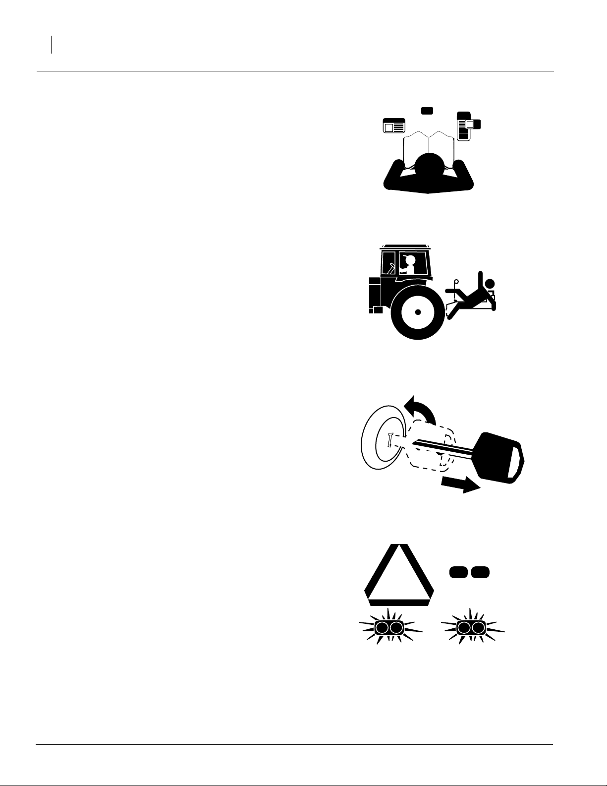
Keep Riders Off Machinery
Riders obstruct the operator’s view. Riders could
be struck by foreign objects or thrown from the
machine.
▲ Never allow children to operate equipment.
▲ Keep all bystanders away from machine dur-
ing operation.
Shutdown and Storage
▲ Lower drill, put tractor in park, turn off engine,
and remove the key.
▲ Secure drill using blocks and supports pro-
vided.
▲ Detach and store drill in an area where chil-
dren normally do not play.
Use Safety Lights and Devices
Slow-moving tractors and towed implements can
create a hazard when driven on public roads.
They are difficult to see, especially at night.
▲ Use flashing warning lights and turn signals
whenever driving on public roads.
▲ Use lights and devices provided with imple-
ment.
OFF
202-499m
8/17/2006
Page 5
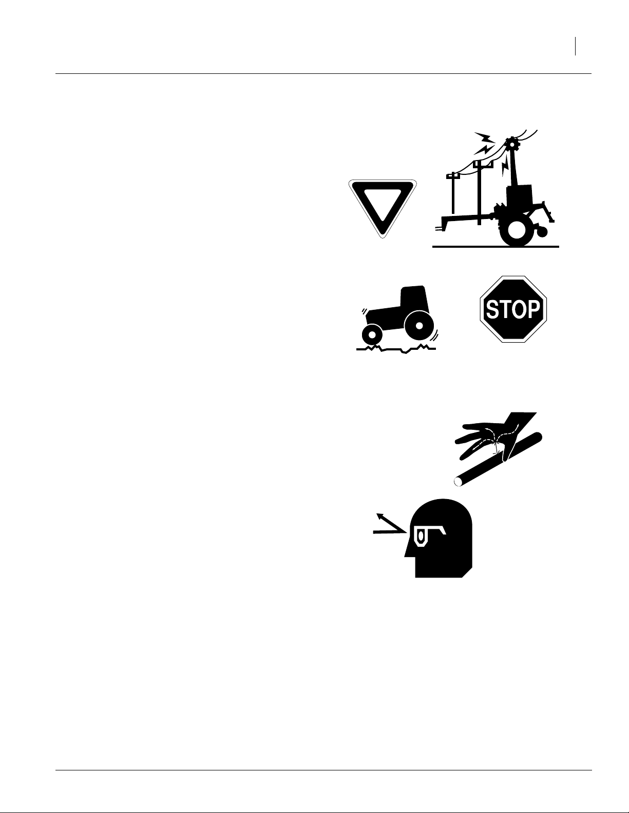
Transport Machinery Safely
Maximum transport speed for implement is 20
mph. Some rough terrains require a slower
speed. Sudden braking can cause a towed load to
swerve and upset.
▲ Do not exceed 20 mph. Never travel at a
speed which does not allow adequate control
of steering and stopping. Reduce speed if
towed load is not equipped with brakes.
▲ Comply with state and local laws.
▲ Do not tow an implement that, when fully
loaded, weighs more than 1.5 times the weight
of towing vehicle.
▲ Carry reflectors or flags to mark drill in case of
breakdown on the road.
▲ Keep clear of overhead power lines and other
obstructions when transporting. Refer to transport dimensions under “Specifications and
Capacities,” page 35.
Important Safety Information
3
Avoid High Pressure Fluids
Escaping fluid under pressure can penetrate the
skin, causing serious injury.
▲ Avoid the hazard by relieving pressure before
disconnecting hydraulic lines.
▲ Use a piece of paper or cardboard, NOT
BODY PARTS, to check for suspected leaks.
▲ Wear protective gloves and safety glasses or
goggles when working with hydraulic systems.
▲ If an accident occurs, see a doctor immedi-
ately. Any fluid injected into the skin must be
surgically removed within a few hours or gangrene may result.
8/17/2006
202-499m
Page 6

2SNG24 & 2SNG30
4
Practice Safe Maintenance
▲ Understand procedure before doing work. Use
proper tools and equipment. Refer to this manual for additional information.
▲ Work in a clean, dry area.
▲ Lower the drill, put tractor in park, turn off
engine and remove key before performing
maintenance.
▲ Make sure all moving parts have stopped and
all system pressure is relieved.
▲ Allow drill to cool completely.
▲ Disconnect battery ground cable (-) before
servicing or adjusting electrical systems or
before welding on drill.
▲ Inspect all parts. Make sure parts are in good
condition and installed properly.
▲ Remove buildup of grease, oil or debris.
▲ Remove all tools and unused parts from drill
before operation.
Prepare for Emergencies
▲ Be prepared if a fire starts.
▲ Keep a first aid kit and fire extinguisher handy.
OFF
▲ Keep emergency numbers for doctor, ambu-
lance, hospital and fire department near
phone.
Wear Protective Equipment
▲ Wear protective clothing and equipment.
▲ Wear clothing and equipment appropriate for
the job. Avoid loose-fitting clothing.
▲ Because prolonged exposure to loud noise
can cause hearing impairment or hearing loss,
wear suitable hearing protection such as earmuffs or earplugs.
▲ Because operating equipment safely requires
your full attention, avoid wearing radio headphones while operating machinery.
911
202-499m
8/17/2006
Page 7
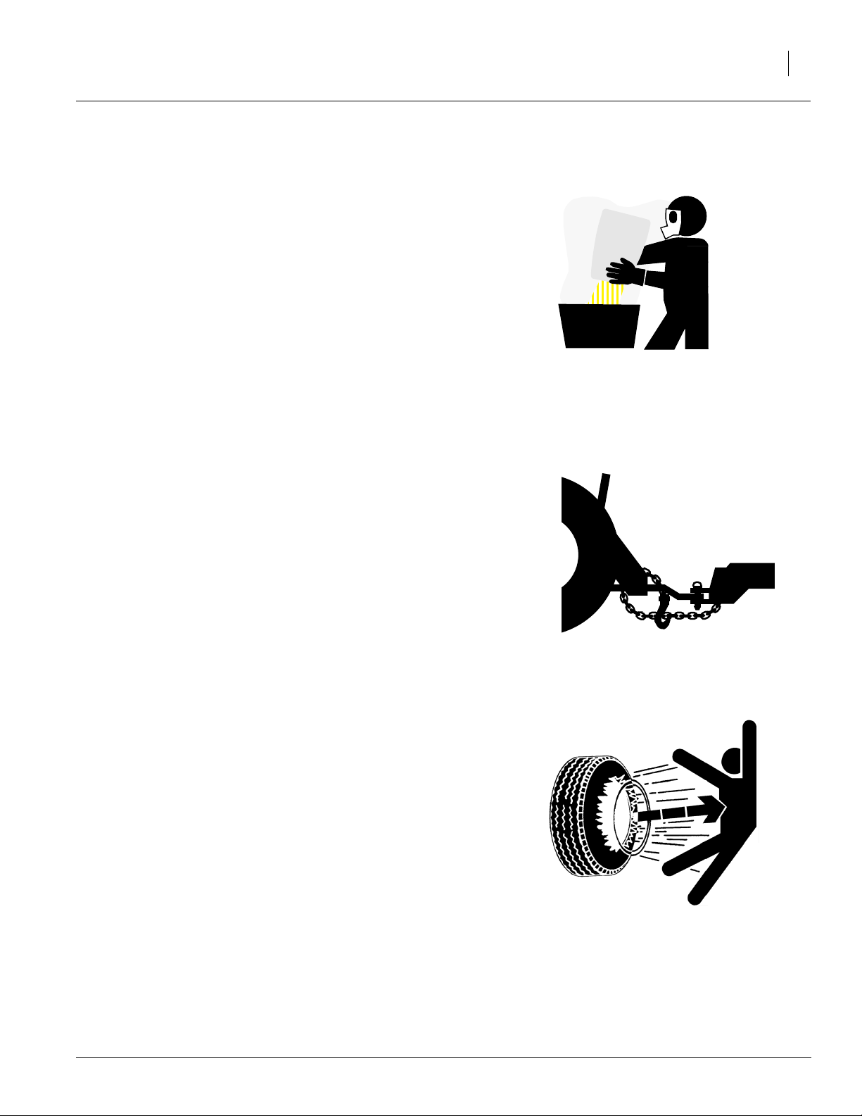
Handle Chemicals Properly
Agricultural chemicals can be dangerous. Improper use can seriously injure persons, animals,
plants, soil and property.
▲ Read and follow chemical manufacturer’s
instructions.
▲ Wear protective clothing.
▲ Handle all chemicals with care.
▲ Avoid inhaling smoke from any type of chemi-
cal fire.
▲ Store or dispose of unused chemicals as
specified by chemical manufacturer.
Use A Safety Chain
▲ Use a safety chain to help control drawn
machinery should it separate from tractor
drawbar.
Important Safety Information
5
▲ Use a chain with a strength rating equal to or
greater than the gross weight of towed
machinery.
▲ Attach chain to tractor drawbar support or
other specified anchor location. Allow only
enough slack in chain to permit turning.
▲ Replace chain if any links or end fittings are
broken, stretched or damaged.
▲ Do not use safety chain for towing.
Tire Safety
Tire changing can be dangerous and should be
performed by trained personnel using correct
tools and equipment.
▲ When inflating tires, use a clip-on chuck and
extension hose long enough for you to stand
to one side–not in front of or over tire assembly. Use a safety cage if available.
▲ When removing and installing wheels, use
wheel-handling equipment adequate for
weight involved.
8/17/2006
202-499m
Page 8
2SNG24 & 2SNG30
6
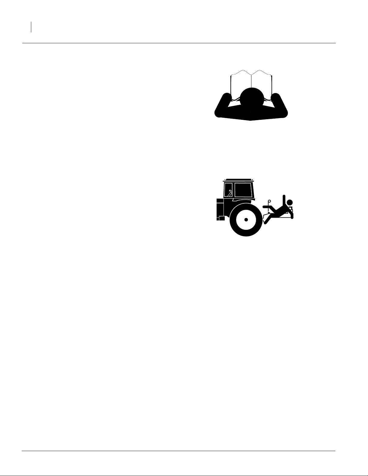
Safety At All Times
Thoroughly read and understand the instructions
in this manual before operation. Read all instructions noted on the safety decals.
▲ Be familiar with all drill functions.
▲ Operate machinery from the driver’s seat only.
▲ Do not leave drill unattended with tractor
engine running.
▲ Do not dismount a moving tractor. Dismount-
ing a moving tractor could cause serious injury
or death.
▲ Do not stand between the tractor and drill dur-
ing hitching.
▲ Keep hands, feet and clothing away from
power-driven parts.
▲ Wear snug-fitting clothing to avoid entangle-
ment with moving parts.
▲ Make sure all persons are clear of working
area.
▲ Do not turn tractor too tightly, causing drill to
ride up on wheels. This could cause personal
injury or equipment damage.
Safety Decals
Your implement comes equipped with all safety
decals in place. They were designed to help you
safely operate your implement.
▲ Read and follow decal directions.
▲ Keep all safety decals clean and legible.
▲ Replace all damaged or missing decals. Order
new decals from your Great Plains dealer.
Refer to this section for proper decal placement.
▲ When ordering new parts or components, also
request corresponding safety decals.
▲ To install new decals:
1. Clean the area on which the decal is to be
placed.
2. Peel backing from decal. Press firmly on
surface, being careful not to cause air
bubbles under decal.
202-499m
8/17/2006
Page 9
20171
Important Safety Information
818-003C
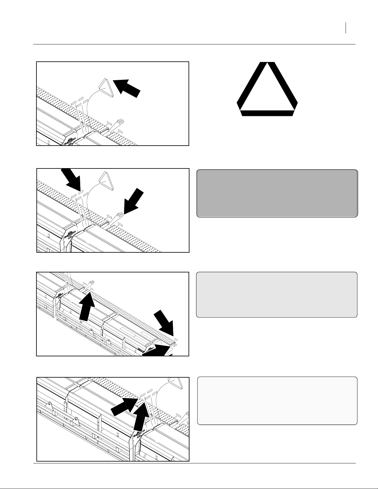
Slow Moving Vehicle Sign
Left-hand box, inside panel
7
20171
20171
838-266C
Red Reflectors
Inside ends of walkboards and boxes; four
decals total
838-265C
Amber Reflectors
Outside ends of walkboards; left and right
side on rear of walkboards; six decals total
20171
8/17/2006
838-267C
Daytime Reflectors
Inside ends of boxes; two decals total
202-499m
Page 10
2SNG24 & 2SNG30
8
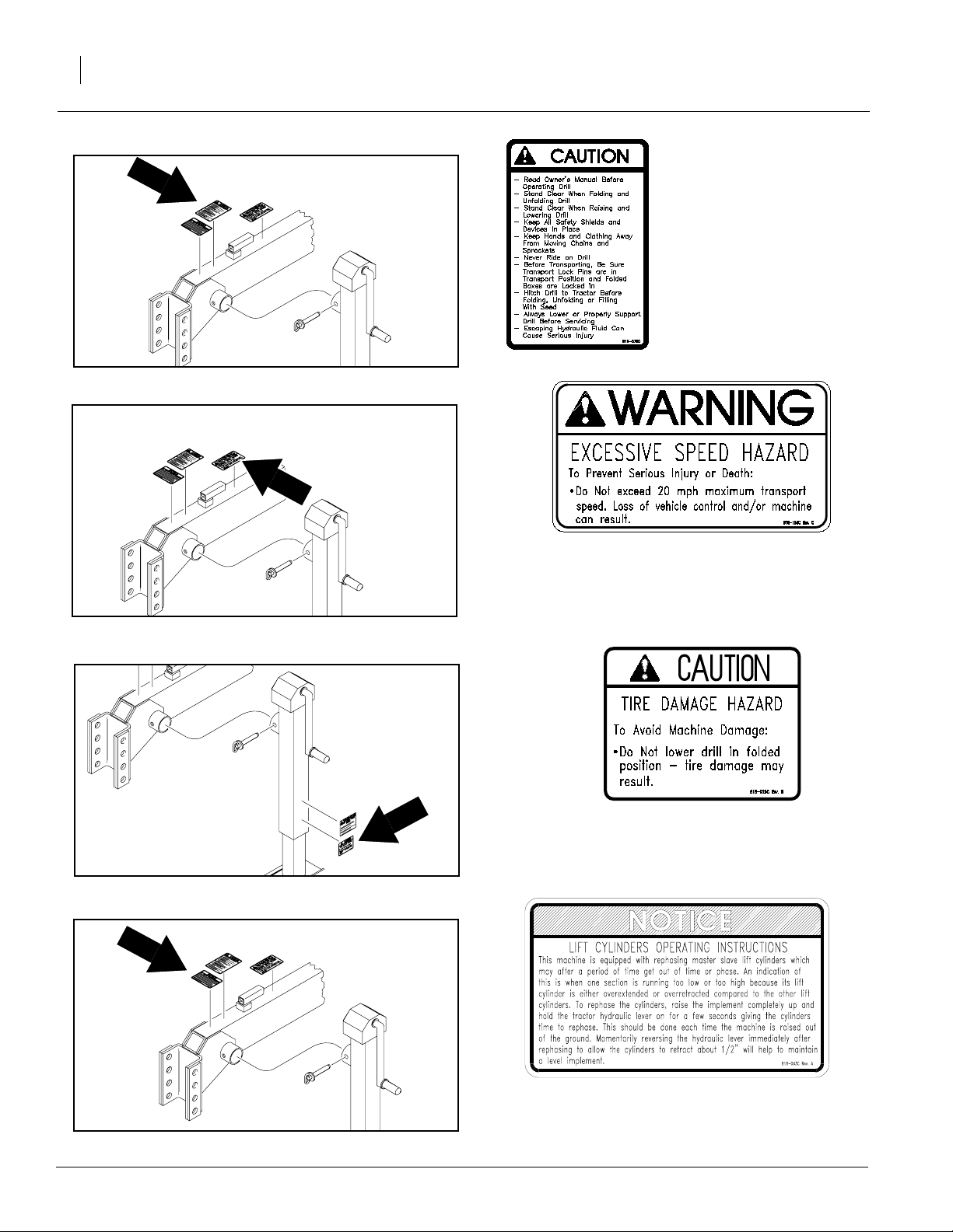
818-078C
Caution FP-HC-MF-24&3
Drill tongue
20171
20171
20171
818-188C
Warning Excessive
Speed Hazard
Drill tongue
818-020C
Tire Damage Hazard
Drill tongue jack
202-499m
20171
818-043C
Lift cylinders operating instructions
Drill tongue
8/17/2006
Page 11
20171
Important Safety Information
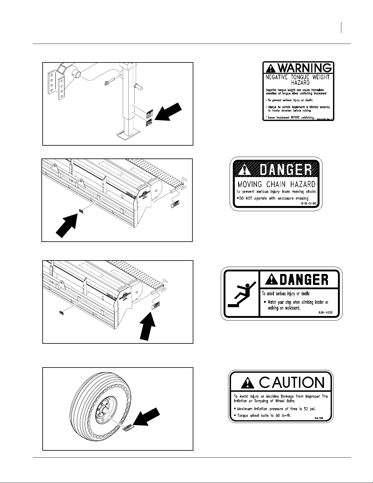
818-019C
Warning Neg Tongue Wt
Drill tongue jack
9
20171
20171
818-518C
Moving Chain Hazard
Also found on Small Seeds Attachment, Na-
tive Grass
838-102C
Falling Hazard
8/17/2006
20171
818-752C
Caution Tire 52 PSI
Transport-wheel rims; four decals total
202-499m
Page 12
2SNG24 & 2SNG30
10
13734
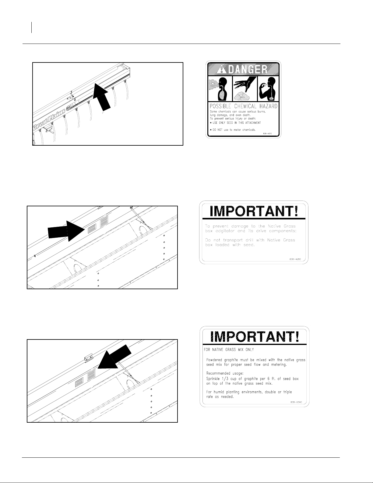
838-467C
Decal Underside of Lid, Small Seeds Box
21839
21839
838-428C
Important to prevent damage
838-634C
Important for native grass mix only
202-499m
8/17/2006
Page 13

Introduction
Great Plains welcomes you to its growing family of
new product owners. This drill has been designed
with care and built by skilled workers using quality
materials. Proper setup, maintenance and safe
operating practices will help you get years of satisfactory use from the machine.
Description of Unit
The 2SNG24 is a 24 foot pull-type seeding implement. The 2SNG30 is a 30 foot pull-type seeding
implement. Both drills are designed for minimum
till conditions. The opener disks clear away crop
residue and open a seed trench. Seed tubes between the opener disks place seed in the trench,
and press wheels firm soil over the seed. The
press wheels also gauge opener depth.
Introduction
11
20160
Intended Usage
Use this drill to seed grasses or production-agriculture crops or to seed over existing grass
stands.
Models Covered
2SNG24 and 2SNG30
2SNG
8/17/2006
202-499m
Page 14

2SNG24 & 2SNG30
12
Using This Manual
This manual will familiarize you with safety, assembly, operation, adjustments, troubleshooting
and maintenance. Read this manual and follow
the recommendations to help ensure safe and efficient operation.
The information in this manual is current at printing. Some parts may change to assure top
performance.
Definitions
The following terms are used throughout this
manual.
Right-hand and left-hand as used in this manual
are determined by facing the direction the machine will travel while in use unless otherwise
stated.
IMPORTANT: A crucial point of information related to the preceding topic. For safe and correct operation, read and follow the directions
provided before continuing.
NOTE: Useful information related to the preceding topic.
202-499m
8/17/2006
Page 15

Owner Assistance
If you need customer service or repair parts, contact a Great Plains dealer. They have trained
personnel, repair parts and equipment specially
designed for Great Plains products.
Your machine’s parts werespecially designed and
should only be replaced with Great Plains parts.
Always use the serial and model number when ordering parts from your Great Plains dealer.
Record your drill model and serial number here for
quick reference:
Model Number:__________________________
Serial Number: ___________________________
Your Great Plains dealer wants you to be satisfied
with your new machine. If you do not understand
any part of this manual or are not satisfied with the
service received, please take the following
actions.
Introduction
13
1. Discuss the matter with your dealership service manager. Make sure they are aware of
any problems so they can assist you.
2. If you are still unsatisfied, seek out the owner
or general manager of the dealership.
3. For further assistance write to:
Product Support
Great Plains Mfg. Inc., Service Department
PO Box 5060
Salina, KS 67402-5060
8/17/2006
202-499m
Page 16

2SNG24 & 2SNG30
14
Assembly Instructions & Set Up
Before You Start
Read and understand the operator’s manual for
your drill. A basic understanding of how the drill
works will aid in the assembly and setup of your
drill.
Before attempting to assemble the drill use the following as a check list. Having all the needed parts
and equipment readily at hand will speed up your
assembly task and will make the job as safe as
possible.
Check for all major frame components
!
CAUTION
Be familiar with the term NEGATIVE TONGUE
WEIGHT. Be aware of the special precautions you
should take when working with an implement that can
develop Negative Tongue Weight.
Have a minimum of twopeople on hand while
assembling the drill.
Check for fasteners and pins that were
shipped with the drill.
Note: All hardware coming from the factory has
been installed in the location where it will be used.
If a part or fastener is temporarily removed for assembly reasons, remember where it goes. Keep
the parts separated.
If a pin, bolt or other part has been removed
and you are unsure where it is used, use the parts
manual for this drill to identify it. Be sure the part
gets used in the correct location.By double checking while you assemble, you will lessen the
chance of using a bolt incorrectly that may be
needed later.
Have a forklift or loader along with chains
and safety stands that are sized for the job ready
for the assembly task.
Have a tractor with remote hydraulics ready
to attach to the tongue. The tongue must be anchored to a large enough tractor to overcome the
negative tongue weight that will be present when
the boxes are attached to the frame. The hydraulics will aid in raising and lowering the drill to align
pins and bolts during assembly.
202-499m
8/17/2006
Page 17

15
Assembling The Drill
Refer to Figure 1 on page 15
1. Read and understand the previous section
Before You Start.
2. Read "Practice Safe Maintenance," page 4,
before assembling drill.
3. Set the tongue (1) approximately 21" off the
ground in a horizontal position with stable
blocking for support.
4. Raise the mainframe (2) up, keeping the side
members horizontal. Position the mainframe
(2) over the tongue (1) and lower into position.
5. Secure tongue (1) to main frame (2) with six
1" x 2 1/2" long bolts (3), lock washers and
nuts.
6. Attach the tongue screw jack (4) in a vertical
position and remove blocking so the unit is on
the ground.
7. Remove the safety wires from each hydraulic
cylinder rod clevis between the tires.
8. Slide the hydraulic hoses from the mainframe
through the tongue and pull them out at the
tractor end. Attach tractor male couplers to
the hydraulic hoses.
9. Hook tractor up to the tongue and plug hydraulic connectors into the tractor. With tractor running at an idle speed charge the drill
hydraulic system. (Be sure your tractor has
plenty of hydraulic fluid. This system requires
approximately 3.3 gallons.) When your drill
frame raises for the first time, one lift cylinder
will extend fully before the other one begins to
move. Once the first cylinder is fully extended
continue to hold yourtractor valve in the same
position for at least 60 seconds after the second lift cylinder has fully extended. The reason for the unevenness of raising for the first
time is because your drill is equipped with
master and slave rephasing cylinders. Raise
and lower the frame several times to be sure
there is no binding or problems with your lift
system. Refer to "Tractor Hydraulic Hookup,"
page 18, for additional information.
10. Attach the gauge-wheel turnbuckle (5) to the
gauge-wheel arm (6) on each drill and then
mount the wheel (7) and tire.
11. Position the two drill boxes in line, end to end,
with the end chain drive sprockets outboard
and approximately 3" between the drill boxes.
Drills on 8" row spacing and narrower will
have 8" spacing at disks between boxes.
12. Using the tractor, back the drill main frame up
to the center of the two drill boxes (8). When
close, position the posts (9) on each side of
the main frame so the face of the post mounting angles are toward the drill frames. Attach
the post (9) to the drill frames (8) using eight
5/8 x 3 1/2 x 5" long U-bolts (10), lockwashers
(11) and nuts (12). With the U-bolts (10) left
loose, slide the drill frames (8) inward so that
the lugs (13) welded to the drill frames are up
tight against the post angles. Tighten all the
nuts on the U-bolts.
13. Attach frame adjustment link (14) from the
drill frame to the pivot post using the clevis pin
(15) with hairpin cotters. Pin to pin should be
approximately 37".
14. Locate drill transport stabilizer frame (16)
against the locator stop on the box frame. Using 5/8" U-bolts (17), lock washers (18) and
nuts (19), mount stabilizer to box frame.
15. Adjust clevis end of pull bars (20) so that the
distance from the center line to center line of
pull bar pin holes is approximately 134 1/4".
16. Mount pull bars to drill transport stabilizer
frames (16) and tongue slide (21). With the
tongue slide in the back position against its
stop, adjust pull bar lengths so boxes are in
line with one another and parallel to the back
edge of the mainframe.
17. Extend the main lift cylinder (22) and place
the transport lock pins (23) in the transport
position through the holes in the mainframe
axle side tube.
18. Fold the drill making sure that the tongue slide
(21) moves smoothly up the tongue. When
drill boxes are almost folding in, stop and adjust the post-frame adjustment links on each
box so that the tang (24) on each drill transport stabilizer frame lines up with the nest (25)
on the front of the main frame. Fold drill completely closed.
19. With tongue slide (21) forward on the tongue
and drill folded completely, position the pull
bar lock pin (26) across the top of the tongue
slide. Adjust the transport lock bolt (27) on top
8/17/2006
202-499m
Page 18

2SNG24 & 2SNG30
16
and front of tongue up against lock pin with
1/16" clearance and lock the jam nut. This pin
prevents the drill from unfolding when in
transport.
Do not lower drill while in folded position.
20. Check to see that all nuts are tightened. See
the "Torque Values Chart," page 36, for
torque specifications.
202-499m
11505
Figure 1
Assembly
8/17/2006
Page 19

Tractor Requirements
Great Plains 2-Section Folding Drills are engineered to be used with tractors having a standard
drawbar.
To operate your Great Plains Folding Drill in most
field conditions, a tractor of 125 minimum horsepower for 24’ drills and 150 minimum horsepower
for 30’ drills should be used.
Tractor Draw Bar Hookup
Refer to Figure 2, 3 and 4
Figure 2
Single Strap Hitch
Tractor Requirements
11638
17
1. 1.The hitch can be used as either a single
strap, clevis or combination hitch as shown in
Figure 2 Single Strap Hitch, Figure 3 Clevis
Hitch and Figure 4 Combination Hitch.
!
CAUTION
This drill has both positive and negative tongue
weight. Never unhook from tractor with boxes Unfolded and Raised off the ground.
2. When using the combination hitch, remove
lower strap when hooking up to a clevis-type
tractor drawbar. Spacers between the drawbar and hitch may be added to eliminate
some of the movement of the tongue caused
from positive to negative tongue weight.
Two hitch sizes are available: The small hole hitch
with or without the hammer strap (1 1/4" maximum pin diameter) and the large hole hitch
without a hammer strap (up to 1 1/2" diameter
pin). The small-hole hitch is sold as standard
equipment.
The mounting holes in the hitch have been offset
so the hitch can be turned over and bolted on in
three different positions giving you six different
hitch heights. On the clevis-type hitch, always
mount the thinner strap on the bottom.
11637
Figure 3
Clevis Hitch
17274
Figure 4
Combination Hitch
8/17/2006
202-499m
Page 20

2SNG24 & 2SNG30
18
Note: Set hitch so tongue of drill is parallel to
ground when drill is in planting position. Use
tongue jack to level tongue, then find closest setting of hitch to match your tractor drawbar height.
3. Attach safety chain on tongue hitch to tractor
and lock hook securely on chain. Adjust chain
length to remove all slack except what is necessary to permit turning of the drill and tractor.
4. The tongue jack makes it possible to raise or
lower the hitch for tractor unhooking and reconnecting. Always return jack to its horizontal position on top of the tongue at the pull bar
slide stop.
Tractor Hydraulic Hookup
For ease of operation, your tractor should be
equipped with six remote hydraulic outlets (three
pairs). This will allow you to connect one pair to
the drill lift circuit, one pair to your drill fold circuit
and one pair remaining for connection of optional
markers. If your tractor has only four remote outlets (two pairs) and a marker circuit is required, a
marker sequences valve with double selector is
available through your Great Plains dealer.
Hydraulic Hose Hookup
Refer to Figure 5
Great Plains hydraulic hoses are color coded to
help you hookup hoses to your tractor outlets.
Hoses that go to the same remote valve are
marked with the same color.
Color Hydraulic Function
White Fold
Blue Lift
Orange Marker Cylinders
To distinguishhoses on thesame hydraulic circuit,
refer to plastic hose label. Hose under extendedcylinder symbol feeds cylinder base ends. Hose
under retracted-cylinder symbol feeds cylinder
rod ends.
Plastic
hose label
17641
Figure 5
Plastic Hose Label
202-499m
8/17/2006
Page 21

Bleeding Hydraulics
!
WARNING
Escaping fluid under pressure can have sufficient pressure to penetrate the skin. Check all hydraulic lines
and fittings before applying pressure. Fluid escaping
from a very small hole can be almost invisible. Use paper or cardboard, not body parts, and wear heavy
gloves to check for suspected leaks. If injured, seek
medical assistance from a doctor that is familiar with
this type of injury. Foreign fluids in the tissue must be
surgically removed within a few hours or gangrene
will result.
19
NOTE: The SAE O-Ring and JIC 37˚ Flare type
hose connections do not require sealant for reconnecting. They do not require high torque for a
good seal.
IMPORTANT: When using sealant on pipe
threads the friction between the threads is reduced; therefore, be certain not to over tighten, causing damage to a valve, cylinder port or
fitting.
!
CAUTION
This drill has a negative tongue weight when unfolded
and raised. Be certain that the drill is hitched securely
to your tractor draw bar and be certain the hitch safety
chain is securely attached to the drill hitch and tractor
before raising or unfolding the drill!
Bleeding the Lifting Hydraulic System
This Folding Drill is equipped with rephasing type
hydraulic lift cylinders that require a special procedure for bleeding air from the hydraulic system. If
your dealer has not already prepared the cylinders for transport use, read the following
information carefully. The rephasing cylinders will
not function properly if this bleeding procedure is
not followed. Do not crack hose fittings in order to
bleed air from this system.
screw the adjustment screw in until it bottoms.
Lower the drill until the cylinders become
loose.
2. Unpin the cylinders from the mainframe and
turn the cylinders upside down to a position
where the rod end is higher than the base end.
Support the cylinders in a safe location. One
transport tire may have to be removed in order
to unpin the master cylinder.
3. Start the tractor and run the engine at idle.
With the rod end of the cylinders higher than
the base end, hydraulically extend the cylinders and hold the tractor control lever in position for sixty seconds after the cylinders have
extended to their maximum stroke.
4. Hydraulically retract the cylinders, then repeat
the extending procedure several more times
until both cylinders are free of air and operate
together.
5. Repin the cylinders to themain frameand axle
with the rod end down. If air is tapped in either
cylinder, the affected cylinder will have a
spongy, erratic movement and the machine
will not raise evenly. Refill the tractor hydraulic
fluid reservoir to its proper level.
NOTE: After drill is raised, a slight settling will occur due to the action of the rephasing cylinder
NOTE: Check the hydraulic fluid level in the tractor reservoir and fill to the proper level before
starting this procedure. If the bleeding is performed with a low reservoir supply, there is a
chance of drawing air into the system. System capacity is approximately 3.3 gallons and requires
one pair of remote outlets.
1. If required, raise your drill 1" in order to extend
your lift cylinders a little. Loosen the jam nuts
on top of the transport vertical tubes and
8/17/2006
NOTE: In order to prevent trapped air pockets,
the port on the rod end must be higher than
any other port of the cylinder during the bleeding operation.
NOTE: The folding and transport wing lift cylinders
are not rephasing type cylinders and do not require this bleeding procedure.
202-499m
Page 22

2SNG24 & 2SNG30
20
Bleeding Hydraulics (Cont.)
!
The following section describes a bleeding procedure
that requires you to crack (loosen) a hydraulic fitting.
Be aware that these lines may be under pressure even
with the tractor shut off. Never allow anyone under the
drill when a fitting is opened. Escaping fluid may allow
the drill to suddenly drop. Be aware of the following
medical alert.
Escaping fluid under pressure can have sufficient pressure to penetrate the skin. Check all hydraulic lines
and fittings before applying pressure. Fluid escaping
from a very small hole can be almost invisible. Use paper or cardboard, not body parts, and wear heavy
gloves to check for suspected leaks. If injured, seek
medical assistance from a doctor that is familiar with
this type of injury. Foreign fluids in the tissue must be
surgically removed within a few hours or gangrene
will result.
DANGER
!
WARNING
Bleeding Folding Hydraulics
Note: The drill transport lift systems should be
completely operational before attempting to work
with the folding hydraulic circuit.
Note: The cylinders are double acting but are not
the rephasing type.
1. The first step in charging the fold hydraulic circuit is to make sure the tractor hydraulic fluid
reservoir is filled to the proper level. System
capacity is approximately 2 gallons and requires one pair of remote outlets. If optional
selector is used, rotate to the wing lift position.
2. With the drill fully raised and in the folded position, disconnect the rod end pin on each fold
cylinder and block the cylinders in a location
where they are free to extend and retract without contacting anything.
3. Cycle the fold cylinders in and out several
times to work the air out of the system.
Refer to Figure 6
Figure 6
Wing Fold Hydraulics
4. Retract the hydraulic cylinder and repin the
rod ends.
5. Recheck the tractor reservoir level and add
clean fluid as necessary.
6. It is advisable to fold and unfold the drill several times. The majority of the air should now be
expelled from this system. The remaining air
will gradually be pushed to the tractor during
day to day operations.
Note: If the wing fold cylinders do not operate
properly, clean out the small hole in the elbow fitting on fold cylinders. These orifice are located in
the cylinder elbow as circled.
202-499m
8/17/2006
Page 23

Leveling the Drill
Note: This section describes procedures for leveling the drill on its initial setup. This should be a
one-time adjustment and will not be needed during day-to-day operation. If while using the drill, it
appears to be lifting or planting uneven, check the
following before re-leveling the drill. First, make
sure the tongue is running level to the ground
while running in the field. Be sure to check this if
the drill has been switched to a different tractor.
See "Tractor Draw Bar Hook-Up," page 17. Second, check the lift cylinders. Be sure they are
properly bled, are operating correctly, and do not
have internal oil leaks before using this section to
re-level the drill.
Refer to Figure 7
The opener spring rods located along the back of
the drill boxes are indicators of the level of the drill
because they show the amount of down-pressure
exerted on the disk openers and press wheels. A
level drill will have equal opener down-pressure
from end to end. Check the spring rod cross bolts
at the top of the spring rods to see that they are all
extended about 2 inches above their spring rod
castings, . This is a general dimension and may
vary with the spring down-pressure you require
for different soil conditions and planting depths
(See “Press Wheel Depth Adjustments,” page
28). If you require more downward float of your
openers you may want to increase this dimension.
Keep in mind when this dimension is increased
your upward motion is decreased, limiting the vertical travel of the openers for running over rocks
and other foreign objects.
Figure 7
Opener Spring Rods
Leveling the Drill
10548
21
!
CAUTION
If your openers’ vertical travel is decreased, considerable damage will occur to your openers.
If all the spring rods along the drill extend the
same distance above their castings, the drill is level and you should tighten down the threaded
studs as described in "Transport Wheel Adjustments for Leveling," page 22. If the spring-rod
extensions vary in length, the drill can be leveled
with transport wheel and gauge wheel adjustments. These are described on page 22.
To summarize: After leveling your drill, it should
have the same dimension from the ground to the
box frame at both ends of each box. These adjustments may have to be fined tuned after observing
the drill in the field in actual planting conditions.
8/17/2006
202-499m
Page 24

2SNG24 & 2SNG30
22
Transport Wheel Adjustments For Leveling Drill
When leveling your drill, opener spring rods near the
center of the drill that extend higher above their
spring rod castings than desired can be adjusted by
raising the transport frame. This is done by raising
the drill with the hydraulic lift cylinders. Spring rods
near the center that do not extend high enough are
adjusted by lowering the transport frame by retracting the cylinders.
Refer to Figure 8
Once the spring rods are at the desired setting,
screw the threaded studs on top of the vertical tubes
down as far as possible and secure them with the
jam nuts. This adjustment will stop the lift cylinder
travel at the same point each time the boxes are
lowered for drilling and assures accurate seed
depth control.
Note: If it is noticed that one drill box spring rod extension is different from the other drill box at the
center of your drill, this is a sign that your lift hydraulic master and slave cylinders are out of sequence
with one another. In order to get them back in sequence, simply raise your drill all the way up and
hold your tractor hydraulic control valve lever on for
a few seconds. Now, lower your drill and both cylinders will be in sequence with one another and your
two drill boxes should be at the same level again.
Jam Nut
10672
Figure 8
Threaded Stud
Gauge Wheel Adjustments For Leveling Drill
The openers near the outside of the drill are adjusted by raising or lowering the gauge wheels.
Refer to Figure 9
Raise the drill out of the ground and loosen the jam
nut located near the bottom clevis of the gauge
wheel turnbuckle. This turnbuckle is threaded to allow easy gauge wheel adjustment. By lengthening
the turnbuckle the gauge wheel is lowered, causing
less spring rod extension through the spring rod
casting. By shortening the turnbuckle the gauge
wheel is raised, causing less spring rod to protrude
through the spring rod casting. After adjusting, be
sure the turnbuckle on both gauge wheel arms have
the same pin center dimension.
Shortening the gauge wheel turnbuckle will level the
ends of the drill with the center.
10546
Figure 9
Turnbuckle
202-499m
8/17/2006
Page 25

Box Alignment Adjustments
Pull Bar Adjustments
Refer to Figure 10
With the drill lowered to the ground and completely
unfolded the tongue slide on the tongue should be
back against the stop on the tongue. Adjust the pull
bars length so drill boxes are in line with one another and parallel to the back edge of the main frame.
Leveling the Drill
23
Drill Adjustments
Refer to Figure 11
Put the transport pins in storage position.
Slowly lower the drill until it is on the ground and the
main frame top slide cylinder is fully extended. Pull
the drill forward a few feet to make sure that the
transport and the gauge wheel tires have equal firm
contact with the soil.
Refer to Figure 12
Unfold the drill on a level seedbed typical to your
soil conditions.
10671
Figure 10
Pull Bar Adjustment
Figure 11
Top Slide Cylinder
3”
Approx.
11284
Jam Nut
At the top of both vertical tubes on the transport
frame is a threaded stud and jam nut. Make sure
both studs have approximately the same length of
threads extending above the jam nut (approximately 3”) for most planting conditions.Adjustments may
be required.
8/17/2006
10672
Figure 12
Threaded Stud
202-499m
Page 26

2SNG24 & 2SNG30
24
Operating Procedures
Folding
1. Folding is best achieved on level ground with
the tractor transmission in neutral. Be aware
of the clearance required to fold the drill.
2. Never allow anyone near the drill during folding operations.
Refer to Figure 13
3. When folding the drill, the drill transport stabilizer frame should line up with the nest on the
front of the main frame.
Refer to Figure 14
4. If the stabilizers scrape the wing on the
tongue, the boxes can be raised or lowered by
adjusting the wing adjustment turnbuckle.
10673
Figure 14
Wing Adjustment Turnbuckle
Refer to Figure 15
5. Apply hydraulic pressure to the raising and
lowering system. Raising the drill may be required to free up the transport lock pins in the
vertical tubes for removal. Place pins into
transport position.
6. Fold boxes using hydraulic cylinders. Do this
very slowly and carefully. Serious damage
could occur if done fast and carelessly.
Refer to Figure 16
7. Place the pin in the pull bar transport lock.
This must always be used when transporting
the drill in the folded position.
17269
Figure 15
Transport Lock PIn in Transport Position
10673
Figure 13
Transport Stabilizers in Road Position
!
CAUTION
Do not lower the drill while in folded position!
202-499m
10739
Figure 16
Pull Bar Pin Locked in Transport Position
8/17/2006
Page 27

LIfting
The lift cylinders may after a period of time get out
of time or phase. The effects of this can be seen
when one side of the drill is running too low or too
high because its lift cylinder is either overextended or not retracted compared to the other lift
cylinders.
To rephase the cylinders, raise the drill completely
up and hold the tractor hydraulic lever on for a few
seconds to give the cylinders time to rephase.
This should be done each time the drill is raised
out of the ground. Momentarily reversing the hydraulic lever immediately after rephasing to allow
the cylinders to retract about 1/2" will help in maintaining a level drill.
Note: Understand that having the cylinders become gradually out of time is different than having
air trapped in the system from improper bleeding.
Each condition is corrected differently.
Operating Procedures
25
Unfolding
!
CAUTION
This drill has a negative tongue weight when unfolded
and raised. Be certain that the drill is hitched securely
to your tractor draw bar and be certain the hitch safety
chain is securely attached to the drill hitch and tractor
before raising or unfolding the drill!
1. Unfolding the drill is best achieved on level
ground with the tractor transmission in neutral.
2. Be aware of the clearance requirements of
the unfolding drill. Allow plenty of room to unfold and do not allow anyone in the area of the
drill when unfolding.
Refer to Figure 17
3. Remove pin from pull bar transport lock.
4. Slowly unfold the drill using the hydraulic cylinders. For the first time, watch to be sure the
hydraulic hoses do not get pinched or kinked.
Serious damage could occur if the drill is unfolded carelessly.
Figure 17
Pull Bar Lock Pin in Transport Position
Refer to Figure 18
5. Apply hydraulic pressure to the raising and
lowering system. Lowering the drill may be required to free up the transport lock pins in the
vertical tubes for removal. Place pins into
storage position.
8/17/2006
17268
10730
Figure 18
Pull Bar & Transport Lock Pins in Field Position
202-499m
Page 28

2SNG24 & 2SNG30
26
Transporting
!
CAUTION
This drill should never be pulled faster than 20 miles
per hour!
Before transporting drill:
1. Make sure that hitch is securely attached to
the draw bar of the tractor and that the hitch
safety chain has been securely fastened.
Refer to Figure 19
2. To prevent possible damage in case of hydraulic failure during transport. Always insert
transport lock pins when transporting.
Refer to Figure 20
3. Check to be sure the pull-bar transport lock
pin is in the transport position.
4. Check to see if you have the required air pressure in your transport tires. For proper inflation see “Tire Inflation Chart," page 36.
5. When in transport, use warning lights and
safety hitch chain. Comply with all federal,
state and local laws when traveling on public
roads.
6. Be sure that the drill is properly folded. The
drill boxes must be correctly supported in the
folded position. See "Folding," page 24.
7. Reduce speed of the tractor when transporting over uneven or rough terrain. Avoid all
chuck holes and washboard areas in roads.
8. Reduce speed of the tractor when transporting over hills or steep slopes. Never exceed
20 miles per hour.
9. Use "Slow Moving Vehicle" emblem
for warning vehicles approaching from the
rear.
10. When transporting, remember the drill is wider than your tractor and extreme care must be
taken to allow for safe clearance.
17269
Figure 19
Transport Lock Pin in Transport Position
10739
Figure 20
Pull-Bar Lock Pin in Transport Position
11. Extra care should be taken when transporting
with seed in the box.
202-499m
8/17/2006
Page 29

Parking
The following steps should be done when preparing to store the drill or unhitch it from the tractor.
See also "Storage," page 31, for additional information on the long-term storage of your drill.
1. Raise and fold the drill and place the transport
lock pins in the transport position.
2. Park the drill on a level, solid area.
Refer to Figure 21
3. Remove the jack from its storage post and pin
it on the post located on the left side of the
main tongue.
Operating Procedures
12624
27
4. If the ground is soft, place a board or plate under the jack to widen the ground contact area.
5. Extend the jack until the weight of the tongue
is on the jack and has been removed from the
tractor drawbar.
6. Unplug the drill hydraulic lines from the tractor.
7. Remove the hitch pin and safety chain from
the tractor drawbar.
The following steps should be done when preparing to hitch the drill to the tractor.
8. Raise or lower the drill tongue as needed and
hitch the drill to the tractor draw bar. Always
use a safety chain. Refer to "Tractor Drawbar
Hookup," page 17.
9. Plug the drill hydraulic lines into the tractor remotes.
10. Retract the jack until the weight of the tongue
is resting on the tractor drawbar and install a
minimum 1 1/8" diameter drawbar pin with
safety clip.
Refer to Figure 22
11. Remove the jack from the side of the tongue
and pin iton the storage post located on top of
the main tongue.
Figure 21
Jack in Vertical Position
12625
Figure 22
Jack in Transport Position
Note: If the drill is being hitched up and operated
for the first time, it is important to follow the safety,
setup, adjustment, bleeding and operating information in the front of this manual.
8/17/2006
202-499m
Page 30

2SNG24 & 2SNG30
28
Adjustments
Press Wheel Opener Linkage Depth
Adjustment
Attached to the rear of each opener is one of several optional press wheels. The press wheel and
its mechanism provide two important functions:
1. The press wheel closes the furrow and gently
presses the soil over the seed.
To provide consistent seed firming, the press
wheel is free to move downward from its normal
operating position. This system maintains pressing action even if the opener body is lifted as a
result of the opener disks encountering an obstruction or hard soil.
2. The press wheel rolls on the ground providing
depth control to the opener and seed.To
maintain a consistent planting depth, the relationship between the bottom of the opener
disk-blades and the press wheel is upwardly
fixed. The upward stop is independently adjustable on each opener. The position of the
adjustable stop determines how deep the
seed will be placed.
12100
Figure 23
Direct Link Press Wheel Adjustment
Refer to Figure 23
To change the height of the press wheel, which
automatically changes the seeding depth of the
opener, simply lift the "T" handle located on top of
the opener at the rear and slide forward or rearward until the seeding depth is correct as shown
in the inset in . A spring loaded pin holds the "T"
handle at your setting to maintain the proper
depth.
Disk Opener Spring Pressure Setting
Refer to Figure 24
Each opener spring can be adjusted for down
pressure. This is useful when penetrating hard
soil and for planting in tractor tire tracks. To adjust
the pressure, remove the "W" clip at the bottom of
the spring and place it in a higher hole in the
spring rod for more pressure, and in a lower hole
for less pressure.
12103
Maximum
12102
Minimum
Figure 24
Down Pressure
202-499m
8/17/2006
Page 31

Drill Preparations
Drill Preparations
29
General Notes for Field Operations
Most of the procedures described in this section
require the useof a tractor with hydraulic remotes.
Before proceeding with the first time setup, or before making any adjustments mentioned in this
section, make every effort to obtain and hitch a
tractor to the drill.
24’ DRILL minimum of 125 horsepower
30’ DRILL minimum of 150 horsepower
1. Be certain that the drill tires have the proper
inflation as listed in the "Tire Inflation Chart,"
page 36.
2. Load seed box with seed. Use clean seed to
get the best results. Always have the drill
hitched securely to a tractor with safety chain
connected. Lower the drill before loading.
3. This drill can be transported with a full box of
grain. It is best not to do this unless necessary
because the increased weight does increase
the chances for problems on the road. Do not
exceed 20 miles per hour.
4. Calibrate each seed box for a proper rate
based on the seed that you are drilling. Calibration information is located on the inside of
your box lid or under "Seeding Adjustments,"
in the seed rate book. Make sure the seed
rate is adjusted the same across the entire
drill.
5. If your drill comes equipped with an acremeter, it should be mounted on the left gauge
wheel axle on the outboard side. It will accumulate the total acres drilled with the drill. In
order to find out the acres covered, write
down the beginning reading and subtract it
from the ending reading for the total acres
planted.
to a wider setting.
9. Never back up with openers in ground. If you
do, check all openers to be sure none are
clogged.
10. After lowering the drill into planting position,
observe the drill from the side. Check to see
that the tongue is level to the ground. If it is
not, a hitch height adjustment is needed. See
"Tractor Draw Bar Hookup," page 17. It is especially important to check for this if the drill
has been hitched to a different tractor.
11. This drill is not designed to be turned sharply
in the field. Always lift the drill completely out
of the ground when turning at ends of field
rows and other short-radius turns. If the drill is
not completely raised, the lift hydraulics will
be out of sequence. Refer to "Bleeding Hydraulics," page 19.
12. Never allow anyone to ride on the drill.
13. Maximum seeding speed will vary according
to soil conditions.
14. You can adjust the tension on each disk
spring. This is especially useful in applying
more pressure in tractor tire tracks.
15. Never unhook drill from tractor with
!
boxes unfolded and raised off the ground.
Negative tongue weight is present in this position.
16. Never attempt to lower the drill while in
!
folded position.
6. This drill is offered in different row spacings;
therefore, some of the drill boxes do not have
the same number of seed cups between each
internal box divider. The section with the largest number of cups will tend to empty sooner.
7. Make sure that the seed-cup-dooradjustment
handles are set the same across the drill.
8. If you notice excessive cracking on largegrain seeds, adjust all seed cup door handles
8/17/2006
202-499m
Page 32

2SNG24 & 2SNG30
30
Operating Check List
Before operating your drill for the first time, make
sure you have checked the following items:
1. Read and follow the “Safety at All Times,”
page 6, carefully.
2. Read all the “Operating Procedures," page
24.
3. Check tire pressure. Proper inflation is listed
in the "Tire Inflation Chart," page 36.
4. Inspect the seed cups and seed tubes for foreign matter.
5. Rotate each gauge wheelto see that the drive
system is operating smoothly.
6. Set drive sprockets for the desired drive type.
7. Set seed rate. For calibrating seed rate see
"Seeding Adjustments," in the seed rate
book.
8. Check disk opener scrapers for proper adjustment in order for disk blades to rotate freely.
9. Lubricate the drill as needed.
10. Read and follow the “Drill Preparations,” page
29.
11. Check the drill initially and periodically for
loose bolts, pins and chains.
12. Check for leaks in the hydraulic system. Always use the procedure listed below.
!
WARNING
Escaping fluid under pressure can have sufficient pressure to penetrate the skin. Check all hydraulic lines
and fittings before applying pressure. Fluid escaping
from a very small hole can be almost invisible. Use paper or cardboard, not body parts, and wear heavy
gloves to check for suspected leaks. If injured, seek
medical assistance from a doctor that is familiar with
this type of injury. Foreign fluids in the tissue must be
surgically removed within a few hours or gangrene
will result.
202-499m
8/17/2006
Page 33

Maintenance and Lubrication
Maintenance and Lubrication
31
Maintenance
1. After using your drill for several hours, check
all bolts to be sure they are tight.
2. After using or transporting your drill for several hours, check all wheel lug bolts and nuts.
Be sure they are tight.
3. Disk scrapers should be kept properly adjusted.
4. Alwaysmaintain the proper air pressure in the
gauge wheel and transport tires. For proper
air pressure refer to “Tire Inflation Chart,”
page 36.
5. Before the drill is transported and regularly
during normal operation, check the hitch safety chain. Make sure the chain is properly attached to both the drill and the tractor draw
bar. Inspect the chain and hardware for wear
or other damage. Replace immediately if
needed.
6. After a period of time, the drill boxes may
gradually become out of line with each other.
To correct this condition, refer to " Box Alignment Adjustments," page 23.
3. Listed below are the items you need to lubricate before storing the drill:
a. Clean and oil all roller chains.
b. Seed cup drive sprocket should be oiled
in its square bore. Move seed cup adjustment lever away from the sprocket as far
as possible in order to get the oil back into
the square.
c. Oil knob adjustment trunnion lower pivot
tube on press wheels.
Note: Proper servicing and adjustment is the key
to the long life of any farm implement. With careful
and systematic inspection, you can avoid costly
maintenance, time and repair.
Storage
1. Clean the drill as necessary. Be sure that the
seed boxes, fertilizer box and all feed systems
are completely cleaned out before storing.
2. Lube chain and adjust all roller chains.
Lubrication
1. After using your drill for several hours, check
all bolts to be sure they are tight.
2. Listed below are the items you need to lubricate every 20 to 25 hours of operation:
a. Marker body hinges.
b. Jack shaft bearings.
c. Feeder cup drive sprocket bearings.
d. Post top roller shaft.
e. Box post lower spindles and cross tubes
on main frame.
f. Telescoping axle tube lower roller be-
tween transport tires.
3. Lubricate all fittings as indicated in “Maintenance & Lubrication” on page 31.
4. When storing in transport position, use all
locking devices as described under "Transporting," page 26 and "Operating Procedures," page 24.
5. Apply a light coat of grease to all exposed hydraulic cylinder rods.
6. Seed cup drive sprocket hub should be oiled
in its square bore. Squirt oil on to the square
seed cup shaft and move seed cup adjustment lever back and forth in order to get the oil
back into the square. This is most important
before putting the drill in storage.
7. Store the drill inside if possible. Inside storage
will reduce maintenance and make for a longer drill life.
8/17/2006
202-499m
Page 34

2SNG24 & 2SNG30
32
Troubleshooting
Problem Solution
Uneven seed spacing or uneven
stand
Opener disks not turning freely Check for trash/mud build-up on disk scraper. Readjust scraper.
Actual seeding rate is different
than desired
Check for plugging in seed cup.
Check to see if seed tubes are plugged.
Reduce ground speed.
Check opener disks to see they turn freely.
Use faster drive speed and close seed cup flutes to a more narrow
position.
Spring pressure on openers could be improperly adjusted causing
opener to not penetrate low spots.
Check for trash or mud build-up on Seed-Lok Wheel.
Check to see if scraper is adjusted too tightly and is restricting disk
movement.
Check disk bearings.
Check opener frame for possible damage.
If opener disks turn freely by hand but not in field, reduce down pressure on disk opener.
Check press wheel adjustment for seeding depth.
Check tire pressure. Proper inflation is listed in "Tire Inflation Chart,’
page 36.
Check gauge wheel size. Proper size is 9.5L x 15.
Seed treatment will affect seeding rate if the chemicals build up in
seed cup. Unless cleaned regularly, this build up can cause breakage
of the seed-cup shaft.
Check speed change box setting.
See "Seeding Adjustments," located in the seed rate book, for
instructions on calculating seed rate.
Excessive seed cracking Use slower drive speed and open flutes in seed cup to a wider posi-
tion.
Position seed-cup handles to a lower notch.
Acremeter doesn’t measure
accurately
Check tire pressure. Proper inflation is listed on "Tire Inflation
Chart," page 36.
Check end gauge wheel tire size. Proper size is 9.5L x 15.
Check planting operation for excessive overlap or gaps between
passes.
Loose soil conditions and slippage will cause variations in acres registered.
To check accuracy of acremeter, see "Seeding Adjustments," in the
seed rate book.
Check to be sure your acremeter is for your width of drill.
202-499m
8/17/2006
Page 35

Problem Solution
Uneven seeding depth See "Press Wheel Depth Adjustments," page 28.
See "Tractor Draw Bar Hookup," page 17, and "Leveling the
Drill," page 21.
Troubleshooting
33
Press wheels not compacting soil as
desired
Refer to "Press Wheel Depth Adjustments," page 28. adjustments sections.
Re-adjust press wheel depth to match coulter depth.
Increase down pressure on disk openers.
Grain box not emptying evenly Certain models do not have the same number of seed cups
between each divider of bulkhead. The section with the larger
number of cups will empty sooner.
Seed cups close to the ends of box tend to empty sooner due to
amount of seed available.
Check adjustment levers on each box to see that they are set on
the same indicator number.
Press wheel or openers plugging Drilling in damp or wet conditions may increase this problem.
Openers may be moved from a staggered to an in-line position
to reduce trash thrown from front openers into rear openers.
Reduce down pressure on openers.
Do not back up drill in the field, or stop and allow drill to roll
backwards with openers in the ground.
If using double "V" press wheels, adjust angle bar.
Check Seed-Lok Wheel.
Rubber tire depth control wheels
becoming packed with mud.
Install scrapers.
Reduce spring tension on openers.
Improper folding of drills Adjust post frame adjusting links.
Check hydraulic system for air and oil leaks.
Clean out small orifice fittings in wing cylinders.
Make sure that the wing boxes unfold to a straight line. Check
to see that both pull bars are attached to the boxes at exactly
the same distance inboard from the inboard edge of the drill
box {90"} and both are exactly the same length.
Hydraulic adaptors cracking JIC fittings do not require high torque.
Always use liquid pipe sealant when adding or replacing pipe
thread hydraulic fittings. Plastic sealant tape can crack fittings
and plug hydraulic lines. JIC and O-Ring fittings do not require
sealant. O-Ring fittings require a thin coat of oil on the O-Ring.
Important: When using sealant on pipe threads, the friction
between the threads is reduced; therefore, be certain not to
overtighten causing damage to the cylinders, valves or fittings.
8/17/2006
202-499m
Page 36

2SNG24 & 2SNG30
34
Problem Solution
Seed-cup sprockets locked up or
twisted seed-drive shaft
Raising and lowering drill is rough
and uneven
Hydraulic marker functioning improperly
Check for foreign matter lodged in one or more seed cup
sprockets.
Liquid insecticide from seed has dried within the seed cup.
Remove the build up by disassembling each seed cup and
scrape the foreign substance from the turning surfaces. Note:
Liquid inoculant should be applied with caution and care
should be taken to clean the seeding system after drilling
treated seeds.
Lubricate lower rollers of vertical transport tubes located
between the transport tires.
Check hydraulic fittings for leaks.
Rephasing cylinders not properly bled. See "Bleeding Hydraulics," page 19. When raising drill at end of field, the lifting cylinders should be fully extended to ensure that they are always
rephased. If machine is only raised enough to lift openers out of
the ground, lift cylinders may eventually get out of sequence
and cause uneven seeding depth.
Check all hose fittings and connections for air and oil leaks.
The chain on the folding 3-section marker should be slack when
the marker is both fully extended and fully raised.
Check tractor hydraulic oil level.
Check all bolts and fasteners.
Double selector valve positioned for wing fold. Shift valve to
marker sequence position.
Open needle valve, cycle markers slowly and reset needle valve
if plugged.
Chain-debris/retainer clip Be sure retainer clip open end is facing opposite way of chain
travel.
202-499m
8/17/2006
Page 37

Specifications and Capacities
Specifications and Capacities
20176
35
Drill Row
Spacing
2SNG30 7 1/2” 48 9900 Approx.
2SNG30 10” 36 9200 Approx.
2SNG24 7 1/2” 38 9000 Approx.
2SNG24 10” 28 8200 Approx.
Drill Box Length
Unfolded Drill Width
No. of
Openers
10 ft
15 ft
24 ft 6 in
30 ft 6 in
Drill
Weight
24 ft Drill
30 ft Drill
24 ft Drill
30 ft Drill
Box Capacity 2 Bushels/Foot
Tire Size 9.5L X 15 - 12 Ply
Transport Width 14 ft
Native Grass Attachment Capacity 1 Bushel/Foot Approx.
NOTE: All tires are warranted by the original manufacturer of the tire. Tire warranty information can be found in the brochures included with your Operator’s and Parts Manuals or online at the manufacturer’s websites. For service assistance
or information, contact your nearest Authorized Farm Tire Retailer.
Manufacturer Website
Titan www.titan-intl.com
Goodyear www.goodyearag.com
Firestone www.firestoneag.com
8/17/2006
202-499m
Page 38

2SNG24 & 2SNG30
36
Appendix
Torque Values Chart
Bolt Head Identification
Bolt Head Identification
Bolt Size
(Inches)
1
in-tpi
1/4" - 20 7.4 5.6 11 8 16 12 M 5 X 0.8 436597
1/4" - 28 8.5 6 13 10 18 14 M 6 X 1 7 5 11 8 15 11
5/16 - 18 15 11 24 17 33 25 M 8 X 1.25 17 12 26 19 36 27
5/16" - 24 17 13 26 19 37 27 M 8 X 1 18 13 28 21 39 29
3/8" - 16 27 20 42 31 59 44 M10 X 1.5 33 24 52 39 72 53
3/8" - 24 31 22 47 35 67 49 M10 X 0.75 39 29 61 45 85 62
7/16" - 14 43 32 67 49 95 70 M12 X 1.75 58 42 91 67 125 93
7/16" - 20 49 36 75 55 105 78 M12 X 1.5 60 44 95 70 130 97
1/2" - 13 66 49 105 76 145 105 M12 X 1 90 66 105 77 145 105
1/2" - 20 75 55 115 85 165 120 M14 X 2 92 68 145 105 200 150
9/16" - 12 95 70 150 110 210 155 M14 X 1.5 99 73 155 115 215 160
9/16" - 18 105 79 165 120 235 170 M16 X 2 145 105 225 165 315 230
5/8" - 11 130 97 205 150 285 210 M16 X 1.5 155 115 240 180 335 245
5/8" - 18 150 110 230 170 325 240 M18 X 2.5 195 145 310 230 405 300
3/4" - 10 235 170 360 265 510 375 M18 X 1.5 220 165 350 260 485 355
3/4" - 16 260 190 405 295 570 420 M20 X 2.5 280 205 440 325 610 450
7/8" - 9 225 165 585 430 820 605 M20 X 1.5 310 230 650 480 900 665
7/8" - 14 250 185 640 475 905 670 M24 X 3 480 355 760 560 1050 780
1" - 8 340 250 875 645 1230 910 M24 X 2 525 390 830 610 1150 845
1" - 12 370 275 955 705 1350 995 M30 X 3.5 960 705 1510 1120 2100 1550
1-1/8" - 7 480 355 1080 795 1750 1290 M30 X 2 1060 785 1680 1240 2320 1710
1 1/8" - 12 540 395 1210 890 1960 1440 M36 X 3.5 1730 1270 2650 1950 3660 2700
1 1/4" - 7 680 500 1520 1120 2460 1820 M36 X 2 1880 1380 2960 2190 4100 3220
1 1/4" - 12 750 555 1680 1240 2730 2010
1 3/8" - 6 890 655 1990 1470 3230 2380
1 3/8" - 12 1010 745 2270 1670 3680 2710
1 1/2" - 6 1180 870 2640 1950 4290 3160
1 1/2" - 12 1330 980 2970 2190 4820 3560
Grade 2 Grade 5
N · m2ft-lb3N · m ft-lb N · m ft-lb mm x pitch4N · m ft-lb N · m ft-lb N · m ft-lb
Torque tolerance + 0%, -15% of torquing values. Unless otherwise specified use torque values listed above.
Grade 8
Bolt Size
(Metric)
1
in-tpi = nominal thread diameter in inches-threads per inch
4
mm x pitch = nominal thread diameter in millimeters x thread pitch
5.8 8.8 10.9
Class 5.8 Class 8.8 Class 10.9
2
N· m = newton-meters
3
ft-lb= foot pounds
Tire Inflation Chart
Tire Size Inflation
PSI
7.50 x 20" 4-Ply Drill Rib 28 11L x 15" 6-Ply Rib Implement 28
9.0 x 22.5 10-Ply Highway Service 70 70 11L x 15" 12-Ply Rib Implement 52
9.0 x 24" 8-Ply Rib Implement 40 12.5L x 15" 8-Ply Rib Implement 36
9.5L x 15" 6-Ply Rib Implement 32 12.5L x 15" 10-Ply Rib Implement 44
9.5L x 15" 8-Ply Rib Implement 44 16.5L x 16.1" 10-Ply Rib Implement 36
9.5L x 15" 12-Ply Rib Implement 60 41 x 15" x 18 - 22-Ply Rib Implement 44
202-499m
Tire Size Inflation
PSI
8/17/2006
Page 39

Warranty
Great Plains Manufacturing, Incorporated warrants to the original purchaser that this seeding equipment will be free from defects in material
and workmanship for a period of one year from the date of original purchase when used as intended and under normal service and conditions
for personal use; 90 days for commercial or rental purposes. This Warranty is limited to the replacement of any defective part by Great Plains
Manufacturing, Incorporated and the installation by the dealer of any
such replacement part. Great Plains reserves the right to inspect any
equipment or part which are claimed to have been defective in material
or workmanship.
This Warranty does not apply to any part or product which in Great
Plains’ judgement shall have been misused or damaged by accident or
lack of normal maintenance or care, or which has been repaired or altered in a way which adversely affects its performance or reliability, or
which has been used for a purpose for which the product is not designed. This Warranty shall not apply if the product is towed at a speed
in excess of 20 miles per hour.
Claims under this Warranty must be made to the dealer which originally
sold the product and all warranty adjustments must by made through
such dealer. Great Plains reserves the right to make changes in materials or design of the product at any time without notice.
This Warranty shall not be interpreted to render Great Plains liable for
damages of any kind, direct, consequential, or contingent, to property.
Furthermore, Great Plains shall not be liable for damages resulting from
any cause beyond its reasonable control. This Warranty does not extend to loss of crops, losses caused by harvest delays or any expense
or loss for labor, supplies, rental machinery or for any other reason.
No other warranty of any kind whatsoever, express or implied, is
made with respect to this sale; and all implied warranties of merchantability and fitness for a particular purpose which exceed
the obligations set forth in this written warranty are hereby disclaimed and excluded from this sale.
This Warranty is not valid unless registered with Great Plains Manufacturing, Incorporated within 10 days from the date of original purchase.
Appendix
37
8/17/2006
202-499m
Page 40

Great Plains Manufacturing, Inc.
Corporate Office: P.O. Box 5060
Salina, Kansas 67402-5060 USA
 Loading...